EP3498966A1 - Feed beam and method of stiffening the same - Google Patents
Feed beam and method of stiffening the same Download PDFInfo
- Publication number
- EP3498966A1 EP3498966A1 EP17208109.3A EP17208109A EP3498966A1 EP 3498966 A1 EP3498966 A1 EP 3498966A1 EP 17208109 A EP17208109 A EP 17208109A EP 3498966 A1 EP3498966 A1 EP 3498966A1
- Authority
- EP
- European Patent Office
- Prior art keywords
- feed beam
- stiffening
- stiffening element
- basic profile
- feed
- Prior art date
- Legal status (The legal status is an assumption and is not a legal conclusion. Google has not performed a legal analysis and makes no representation as to the accuracy of the status listed.)
- Withdrawn
Links
Images


Classifications
-
- E—FIXED CONSTRUCTIONS
- E21—EARTH OR ROCK DRILLING; MINING
- E21B—EARTH OR ROCK DRILLING; OBTAINING OIL, GAS, WATER, SOLUBLE OR MELTABLE MATERIALS OR A SLURRY OF MINERALS FROM WELLS
- E21B7/00—Special methods or apparatus for drilling
- E21B7/02—Drilling rigs characterised by means for land transport with their own drive, e.g. skid mounting or wheel mounting
- E21B7/025—Rock drills, i.e. jumbo drills
Definitions
- the invention relates to a feed beam of a rock drilling unit.
- the feed beam is an elongated piece comprising support surfaces for supporting and guiding a rock drilling machine.
- the invention further relates to a method of stiffening a feed beam.
- the rock drilling rigs are provided with one or more booms and rock drilling units at distal ends of the booms.
- the rock drilling unit comprises a feed beam along which a rock drilling device is configured to be moved during the drilling procedure.
- Modern feed beams consist of extruded aluminum profiles, which are relatively strong and light in weight.
- the present feed beams have still shown to contain some disadvantages.
- An object of the invention is to provide a novel and improved feed beam.
- the invention further relates to a method of stiffening a feed beam.
- the feed beam according to the invention is characterized by the characterizing features of a first independent apparatus claim.
- the rock drilling unit according to the invention is characterized by the characterizing features of a second independent apparatus claim.
- the method according to the invention is characterized by the charactering features and steps of an independent method claim.
- the feed beam of a drilling unit is an elongated piece comprising a basic profile element provided with support surfaces allowing a rock drilling machine to be supported movably on the feed beam.
- the mentioned basic profile element is reinforced by providing it with one or more stiffening elements made of composite material.
- the composite stiffening elements comprise reinforcing fibers and matrix material.
- the basic profile element and the stiffening elements are made of different materials whereby it is entitled to be named as a hybrid feed beam.
- the feed beam can be construed extremely rigid and still light in weight.
- the included one or more composite elements improve properties of the basic feed beam, which may be made of metallic material.
- the stiffening elements do not substantially increase outer dimensions of the feed beam, which has positive effect on usability of the drilling unit. Further, when the feed beam is stiffer than before, positioning of the feed beam may be more accurate.
- the feed beam may also be provided with versatile auxiliary devices and components since the stiffer structure allows greater payload to be supported to the feed beam. Mounting of the rod and tool handling devices and other auxiliary devices may also be executed more freely than in conventional feed beams.
- One additional benefit is that due to the composite stiffeners fatigue and service life of the feed beam may be extended. To sum up, the hybrid feed beam may enjoy the best material and structural properties of the basic profile elements and the composite stiffeners.
- the basic profile elements and the basic structure of the feed beam may be made of metal material or other such material that withstands external forces without damages and cracks.
- the basic structure is provided with support elements and points for fastening the auxiliary devices and slides of the drilling machine, for example.
- the composite stiffening elements may be located so that the metallic basic structure provides mechanical protection against external forces for the stiffeners.
- the disclosed solution may be implemented with only slight modifications to current aluminum extrusion profiles. Thereby the disclosed solution is also easy to produce and the new feed beam may be retrofitted to the existing drilling units without extensive modifications.
- the feed beam comprises one or more elongated composite rods, which serve as the stiffening elements.
- the composite rods may be prefabricated, the mounting of which elements is straightforward.
- the feed beam comprises one or more elongated pultrusion profiles, which serve as the stiffening elements.
- Pultrusion is an effective manufacturing method for forming rod-like components.
- the feed beam comprises one or more stiffening elements comprising carbon fibers as reinforcements and thermoplastic and/or thermoset resin as matrix or binding material.
- the feed beam is a multi-material structure wherein the basic profile element of the feed beam and the stiffening element are made of different materials.
- the basic structure of the feed beam may consist of one or more extruded high strength aluminum profile sections, and the stiffening element consists of reinforcement fibers and thermoplastic or thermoset plastic matrix material.
- the stiffening element of the feed beam is fastened to the basic profile element of the feed beam by means of an adhesive bonding. Then the stiffening element is an inseparable integrated part of the feed beam. In other words, the stiffening element is mounted in place already at the manufacturing place and cannot be removed without breaking the structure.
- the stiffening element of the feed beam may be a prefabricated item, bonded to the basic profile element. This way, manufacture of the stiffening element may be executed effectively beforehand and still the mounting ensures that the stiffening element serves extremely well as a load bearing element.
- the stiffening element of the feed beam is formed directly against surfaces of the basic profile element.
- the stiffening element is integrated to the structure of the feed beam.
- the stiffening element is an inseparable integrated part of the feed beam and forming process of the stiffening element may comprise the following features or steps: inserting reinforcements, possibly a prefabricated reinforcing structure, inside a hollow space or cavity of the basic profile element; injecting the matrix or binding material inside the space for filling the space; and curing the formed integrated stiffening element.
- the cavity of the basic profile element serves as a mould for the manufacture of the stiffening element. Further, when the stiffening element made of composite material is inside the cavity, then it is automatically perfectly protected against external forces and harsh conditions.
- the stiffening element of the feed beam is laminated against inner or outer surfaces of the basic profile element.
- An advantage of the laminating technique is that number of the laminated layers, their materials as well as directions of the reinforcing fibers may be easily chosen according to the need.
- the laminating technique offers multiple variations to be implemented for the structures and properties of the integrated stiffening elements and portions.
- the included reinforcing layers are relatively easy to laminate together with the matrix material directly on the surfaces of the basic structure of the feed beam.
- prepregs may be implemented.
- the prepregs comprise reinforcement fiber elements which are pre-impregnated with thermoplastic or thermoset resin matrix in a certain ratio.
- the stiffening element of the feed beam is fastened by means of mechanical fastening elements to the basic structure of the feed beam.
- the stiffening element may be a changeable element and it may be substituted if being damaged or when greater payload than originally designed is supported to the feed beam, or when use of the feed beam is changed.
- it may even be possible to retrofit one or more stiffening elements to existing feed beams and to thereby update their structures and properties.
- the mentioned mechanical fastening elements may comprise different type of fastening screws, quick coupling elements, clamps, wedges and corresponding elements.
- the stiffening element of the feed beam is an elongated rod-like piece ends of which are fastened to the basic profile element by means of the mechanical fastening elements.
- the basic profile element may comprise an elongated space, such as a tubular space, inside which the rod-like stiffening element is inserted and only the ends are then fastened. This type of stiffening element is easy to mount and change.
- the mechanical fastening of the stiffening element of the feed beam is dismountable and re-mountable.
- the separate stiffening element is a spare part which is easily mountable and dismountable to a basic structure of the feed beam.
- the spare part may comprise heat and/or pressure activated bonding agent for the fastening.
- the stiffening element is fastened to the basic profile element by means of the mechanical fastening and adhesive bonding.
- the stiffening element may be a rod-like piece the ends of which are fastened by means of screws to the basic feed beam structure and the middle section between the ends may be glued to the feed beam structure, for example. This way the stiffening element is fastened extremely rigidly to the basic feed beam components and may thus receive well forces and increases thereby rigidity of the feed beam.
- the stiffening element of the feed beam is tensioned longitudinally between two structural elements of the basic profile element of the feed beam.
- the tensioning increases significantly rigidity of the stiffening element.
- the stiffening element of the feed beam is a pre-tensioned element as it is disclosed in the previous embodiment.
- the stiffening element is a rod-like piece comprising ends and at least one end is connected to a pre-tensioning element for generating pre-tensioning force for the stiffening element.
- the opposing end may comprise anchoring or locking elements.
- the feed beam comprises one or more stiffening elements which are pre-tensioned by means of at least one pre-tensioning element.
- the pre-tensioning element comprises screw elements. Advantages of the screw element is that great forces can be generated and yet the structure may be simple and durable. The screw elements or members are also inexpensive, easy to use and they offer accurate adjustment.
- the stiffening element is tensioned by means of an external tensioning device during the mounting.
- the tensioning device is removed after the stiffening element is being tensioned and locked to the basic profile element in the tensioned state by means of locking screws of other fastening means.
- the stiffening element mounted to the feed beam may extend from end to end of the feed beam, or alternatively, the stiffening elements may be located only at specific longitudinal portions of the feed beam for stiffening only limited portions of the feed beam.
- cross-section of the basic profile element of the feed beam comprises at least one hollow space enveloped by material of the basic profile. Further, at least one stiffening element of the feed beam is located inside the mentioned space.
- the hollow space wherein the stiffening element is located may be a space dedicated for the stiffening element, or alternatively, it may be a structural space inside which may possibly locate other components and devices belonging to the drilling unit.
- the stiffening element is invisible to the outer side of the feed beam. Then the vulnerable composite structure is protected against damage and dents by means of the structure of the basic profile element.
- a further advantage of this embodiment is that it has no influence to outer dimensions of the cross-section of the basic profile element.
- the cross-section of the basic profile element comprises several corners and at least one of the corners comprises a hollow space provided with the stiffening element.
- Cross-section of the basic profile element may comprise at least one hollow space enveloped by material of the basic profile.
- the cross-section of the basic profile element of the feed beam comprises four corners and each of the corners are provided with the stiffening elements inside the hollow spaces.
- the stiffening elements located at corners are at a distance from the center line of the feed beam which is beneficial according to strength theory.
- the basic profile element of the feed beam is made of aluminum, titanium, magnesium or any other suitable alloy.
- the feed beam may be light-weight and may withstand well moisture and harsh conditions.
- the basic profile element of the feed beam is an extruded profile.
- the basic profile of the feed beam is made of light-weight metal material, such as aluminum, and rigidity of the feed beam structure is improved by means of several carbon composite rods integrated to corners of the profile.
- the carbon composite rods may be pre-tensioned.
- a rock drilling unit comprises a feed beam and a rock drilling machine is supported on the feed beam.
- a feed device is configured to move the drilling machine longitudinally on the feed beam.
- the feed beam of the drilling unit is stiffened by means of one or more composite stiffening elements.
- the rock drilling unit may be arranged to a drilling boom of a rock drilling rig.
- the rock drilling rig may be a surface drilling rig or an underground drilling rig.
- the rock drilling unit may be a production drilling unit or it may be arranged in connection with a rock bolting device, for example.
- the rock drilling device of the rock drilling unit may comprise an impact device for executing percussion drilling, or alternatively, the drilling may be based on rotation of a drilling tool only.
- cross section of the feed beam comprises one or more hollow spaces and the feed beam is stiffened by arranging one or more composite rods into one or more of the hollow spaces.
- the stiffening element is without any fixed fastening to the basic profile element, but instead the separate stiffening element is inserted into a tight space of the basic profile element and is thereby capable to receive forces directed to the feed beam.
- the basic structure of the feed beam is subjected to bending forces, then surfaces of the tight space transmit the bending forces to the inserted rigid stiffening element.
- the feed beam comprises means, such as tensioning screws or apparatuses, for generating longitudinal tensioning force to the stiffening element during the mounting.
- the tensioning of the stiffening elements is executed by means of an external tensioning apparatus used during the mounting phase.
- the feed beam comprises at least one tensioning device allowing changes and adjustment of the longitudinal tensioning force to the stiffening element during the use of the feed beam of the drilling unit. This way the tensioning of the stiffening elements may be adjusted remote controlled of automatically.
- the tensioning device comprises at least one actuator for generating the tensioning force.
- the actuator may be a hydraulic cylinder or motor, for example.
- the feed beam comprises the tension adjusting device as disclosed in the previous embodiment.
- the feed beam further comprises one or more sensors or measuring devices for sensing loadings and forces directed to the feed beam.
- the adjusting device may be controlled on the basis of the sensing data for adjusting the tension caused by the pre-tensioning means.
- the adjusting device may be operated electrically or hydraulically, for example.
- the control of the adjusting device may be automatic or it may be controlled by an operator.
- the adjusting device may be remote controllable.
- the feed beam may comprise a dynamic stiffening system.
- Figure 1 shows a rock drilling rig 1 as an example of a mine vehicle comprising a feed beam.
- rock bolting rigs, charging rigs and measuring vehicles may comprise booms provided with feed beams.
- the improved feed beam disclosed in this patent application may be applied in all type of feed beams implemented in mine operations.
- the rock drilling rig 1 may comprise a movable carrier 2 and one or more booms 3 connected to the carrier 2. At a distal end portion of the boom 3 may be a drilling unit 4.
- the drilling unit 4 may comprise a feed beam 5 and a rock drilling machine 6 supported on it.
- the rock drilling machine 6 may comprise a shank at a front end of the rock drilling machine 6 for connecting a tool 7.
- the drilling unit 4 may comprise one or more rod handling devices 8, such as a tool hold device, a tool changing apparatus or manipulator and a tool magazine or storage.
- one or more additional devices 9 may be supported to the feed beam 5.
- feed beam is subjected to several different loads during the operations and still it should be light in weight and rigid enough to allow accurate positioning for a drill bit 7b mounted to a front end of the tool 7 comprising one or more drilling rods 7a.
- Figure 1 further disclose drilling axis DA.
- the rock drilling rig 1 is operating in an underground mine space 8, which may be a tunnel, storage hall or corridor, for example.
- Figure 2 discloses a surface rock drilling rig 1 which also comprises a carrier 2, a boom 3 and drilling unit 4 provided with a feed beam 5.
- a rock drilling machine 6 is supported on the feed beam 5 and may be moved in the drilling direction and reverse direction by means of a feed device 10.
- the feed beam 5 may be equipped with needed auxiliary devices and components.
- FIG. 3 discloses a feed beam 5 comprising a basic structure or basic profile element 11, which may be made of metallic material.
- the basic profile element 11 may be made of aluminium material by means of extrusion technique. However other light-weight metallic materials and manufacturing techniques may of course be implemented.
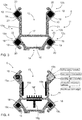
- Cross sectional profile of the disclosed feed beam 5 comprise four corners 12a - 12d, two sides 13a, 13b, a bottom surface 14 and on open top space 15. Between the open top space 15 and the bottom surface 14 is a closed hollow bottom space 16 limited vertically by the bottom surface and an intermediate support 17.
- the bottom space 16 may be left hollow or it may be provided with one or more composite stiffening elements as will be disclosed below.
- the stiffening elements 19 may be rod-like elements and they may be fastened by means of mechanical fastening means and/or by means of gluing or bonding to the basic profile element 11.
- Outer surfaces of the corners 12a - 12d may comprise support surfaces 20 for slide elements of a carriage, which is for supporting a rock drilling rig movably on the feed beam 5.
- the side surface 13a, 13b of the fed beam 5 may comprise second support surfaces 21 for supporting different kind of tool handling devices and elements to the feed beam as well as any auxiliary devices.
- the open top space 15 may receive a feed cylinder or corresponding feed device.
- Figure 4 discloses a feed beam 5 having a similar basic profile element 11 as in Figure 3 .
- the corners 12a - 12d are provided with stiffening elements 19a - 19c.
- the hollow spaces 18 at the corners 12a - 12d may be provided with different type of stiffening elements.
- one or more inner surfaces of the open top space 15 may also be provided with stiffening elements 19d - 19f which may be bonded directly on the surfaces.
- the stiffening elements 19d - 19f may be laminated directly against the surfaces, or they may be pre-fabricated elements which are fastened to the surfaces by means of bonding agents or mechanical fasteners.
- the stiffening elements may have flat outer surfaces or they may comprise protrusions of other surface topography for additionally increasing rigidity.
- the bottom space 16 may also comprise one or more stiffening elements 19g.
- the stiffening element 19g has a T-shaped profile, but it should be understood that other suitable profiles may also be utilized for stiffening the feed beam 5.
- Figure 4 also discloses one possible process of making the stiffening element 19b into the hollow space 18. This method is already disclosed more accurately above in this patent application.
- Figure 5 discloses a feed beam 5 the basic profile element 11 of which corresponds to that shown in Figures 3 and 4 .
- the bottom space 16 may be filled with reinforcements and matrix material so that a bottom space stiffening element 19h is formed.
- the solution of Figure 6 differs from the solution shown in Figure 5 in that several hollow elements 22, such as fibre reinforced tubes, are arranged inside the bottom space 16. Then the inner spaces of the tubes are empty and only the space between the tubes are filled with inserted matrix material and possible fibre material. Thus, an alternative bottom space stiffening element 19i is formed.
- Figure 7 discloses that a basic profile component 11 of basic metallic structure of the feed beam 5 may comprise hollow spaces inside which are arranged rod-type stiffening elements 19j and 19k.
- the stiffening elements 19j, 19k comprise tensioning elements 23 for generating pre-tensioning forces PT for them.
- the tensioning elements 23 may be screw members, wedges of tensioning devices.
- the pre-tensioned stiffening elements may extend from end to end of the feed beam 5 of they may cover only a limited portion of the feed beam.
- Figure 8 illustrates two alternative rod-like stiffening elements 191 and 19m.
- Cross-sectional shapes of the stiffening elements may be selected freely according to the shape of the hollow insertion space and according to needs.
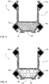
- Figures 9 and 10 show two types of laminated stiffening elements 19n and 19o, which may be formed directly on a surface of the basic profile element 11.
- Figure 10 discloses that the stiffening element 19o may comprise different type of reinforcement layers 24a, 24b having different materials, thicknesses and/or fibre orientations.
- Figure 11 discloses that a stiffening element 19p may comprise a pre-preg element 25.
- Figure 12 discloses that a stiffening element 19q may comprise differing portions 26a, 26b with differing thickness.
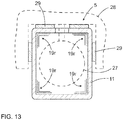
- Figure 13 discloses a feed beam 5 which has a substantially rectangular cross sectional shape. Inside a hollow space may be located a feed cylinder 27 and a carriage 28 may be supported on the feed beam 5 by means of slide elements 29. Inner corners of the basic profile element 11 may be provided with corner stiffening elements 19r.
Landscapes
- Life Sciences & Earth Sciences (AREA)
- Engineering & Computer Science (AREA)
- Geology (AREA)
- Mining & Mineral Resources (AREA)
- Physics & Mathematics (AREA)
- Environmental & Geological Engineering (AREA)
- Fluid Mechanics (AREA)
- General Life Sciences & Earth Sciences (AREA)
- Geochemistry & Mineralogy (AREA)
- Earth Drilling (AREA)
Abstract
The invention relates to a feed beam, rock drilling unit and to a method. The feed beam comprises a metallic base profile component and one or more composite stiffening elements.
Description
- The invention relates to a feed beam of a rock drilling unit. The feed beam is an elongated piece comprising support surfaces for supporting and guiding a rock drilling machine.
- The invention further relates to a method of stiffening a feed beam.
- The field of the invention is defined more specifically in the preambles of the independent claims.
- In mines and at other work sites different type of rock drilling rigs are used. The rock drilling rigs are provided with one or more booms and rock drilling units at distal ends of the booms. The rock drilling unit comprises a feed beam along which a rock drilling device is configured to be moved during the drilling procedure. Modern feed beams consist of extruded aluminum profiles, which are relatively strong and light in weight. However, the present feed beams have still shown to contain some disadvantages.
- An object of the invention is to provide a novel and improved feed beam. The invention further relates to a method of stiffening a feed beam.
- The feed beam according to the invention is characterized by the characterizing features of a first independent apparatus claim.
- The rock drilling unit according to the invention is characterized by the characterizing features of a second independent apparatus claim.
- The method according to the invention is characterized by the charactering features and steps of an independent method claim.
- An idea of the disclosed solution is that the feed beam of a drilling unit is an elongated piece comprising a basic profile element provided with support surfaces allowing a rock drilling machine to be supported movably on the feed beam. The mentioned basic profile element is reinforced by providing it with one or more stiffening elements made of composite material. The composite stiffening elements comprise reinforcing fibers and matrix material. The basic profile element and the stiffening elements are made of different materials whereby it is entitled to be named as a hybrid feed beam.
- An advantage of the disclosed solution is that the feed beam can be construed extremely rigid and still light in weight. Thus, the included one or more composite elements improve properties of the basic feed beam, which may be made of metallic material. The stiffening elements do not substantially increase outer dimensions of the feed beam, which has positive effect on usability of the drilling unit. Further, when the feed beam is stiffer than before, positioning of the feed beam may be more accurate. The feed beam may also be provided with versatile auxiliary devices and components since the stiffer structure allows greater payload to be supported to the feed beam. Mounting of the rod and tool handling devices and other auxiliary devices may also be executed more freely than in conventional feed beams. One additional benefit is that due to the composite stiffeners fatigue and service life of the feed beam may be extended. To sum up, the hybrid feed beam may enjoy the best material and structural properties of the basic profile elements and the composite stiffeners.
- According to an embodiment, the basic profile elements and the basic structure of the feed beam may be made of metal material or other such material that withstands external forces without damages and cracks. The basic structure is provided with support elements and points for fastening the auxiliary devices and slides of the drilling machine, for example. The composite stiffening elements may be located so that the metallic basic structure provides mechanical protection against external forces for the stiffeners.
- According to an embodiment the disclosed solution may be implemented with only slight modifications to current aluminum extrusion profiles. Thereby the disclosed solution is also easy to produce and the new feed beam may be retrofitted to the existing drilling units without extensive modifications.
- According to an embodiment, the feed beam comprises one or more elongated composite rods, which serve as the stiffening elements. The composite rods may be prefabricated, the mounting of which elements is straightforward.
- According to an embodiment, the feed beam comprises one or more elongated pultrusion profiles, which serve as the stiffening elements. Pultrusion is an effective manufacturing method for forming rod-like components.
- According to an embodiment, the feed beam comprises one or more stiffening elements comprising carbon fibers as reinforcements and thermoplastic and/or thermoset resin as matrix or binding material.
- According to an embodiment, the feed beam is a multi-material structure wherein the basic profile element of the feed beam and the stiffening element are made of different materials. The basic structure of the feed beam may consist of one or more extruded high strength aluminum profile sections, and the stiffening element consists of reinforcement fibers and thermoplastic or thermoset plastic matrix material.
- According to an embodiment, the stiffening element of the feed beam is fastened to the basic profile element of the feed beam by means of an adhesive bonding. Then the stiffening element is an inseparable integrated part of the feed beam. In other words, the stiffening element is mounted in place already at the manufacturing place and cannot be removed without breaking the structure.
- According to an embodiment, the stiffening element of the feed beam may be a prefabricated item, bonded to the basic profile element. This way, manufacture of the stiffening element may be executed effectively beforehand and still the mounting ensures that the stiffening element serves extremely well as a load bearing element.
- According to an embodiment, the stiffening element of the feed beam is formed directly against surfaces of the basic profile element. In other words, the stiffening element is integrated to the structure of the feed beam.
- According to an embodiment, the stiffening element is an inseparable integrated part of the feed beam and forming process of the stiffening element may comprise the following features or steps: inserting reinforcements, possibly a prefabricated reinforcing structure, inside a hollow space or cavity of the basic profile element; injecting the matrix or binding material inside the space for filling the space; and curing the formed integrated stiffening element. In this embodiment the cavity of the basic profile element serves as a mould for the manufacture of the stiffening element. Further, when the stiffening element made of composite material is inside the cavity, then it is automatically perfectly protected against external forces and harsh conditions.
- According to an embodiment, the stiffening element of the feed beam is laminated against inner or outer surfaces of the basic profile element. An advantage of the laminating technique is that number of the laminated layers, their materials as well as directions of the reinforcing fibers may be easily chosen according to the need. In other words, the laminating technique offers multiple variations to be implemented for the structures and properties of the integrated stiffening elements and portions. The included reinforcing layers are relatively easy to laminate together with the matrix material directly on the surfaces of the basic structure of the feed beam. As an alternative to the machine or manually laminated layers, prepregs may be implemented. The prepregs comprise reinforcement fiber elements which are pre-impregnated with thermoplastic or thermoset resin matrix in a certain ratio.
- According to an embodiment, the stiffening element of the feed beam is fastened by means of mechanical fastening elements to the basic structure of the feed beam. Then the stiffening element may be a changeable element and it may be substituted if being damaged or when greater payload than originally designed is supported to the feed beam, or when use of the feed beam is changed. Furthermore, it may even be possible to retrofit one or more stiffening elements to existing feed beams and to thereby update their structures and properties. The mentioned mechanical fastening elements may comprise different type of fastening screws, quick coupling elements, clamps, wedges and corresponding elements.
- According to an embodiment, the stiffening element of the feed beam is an elongated rod-like piece ends of which are fastened to the basic profile element by means of the mechanical fastening elements. Thus, in this embodiment only the ends of the stiffening element are fastened to the basic profile element and the portion between the ends is free of fastening with the basic profile element. The basic profile element may comprise an elongated space, such as a tubular space, inside which the rod-like stiffening element is inserted and only the ends are then fastened. This type of stiffening element is easy to mount and change.
- According to an embodiment, the mechanical fastening of the stiffening element of the feed beam is dismountable and re-mountable. The separate stiffening element is a spare part which is easily mountable and dismountable to a basic structure of the feed beam. Alternatively or in addition to the spare part may comprise heat and/or pressure activated bonding agent for the fastening.
- According to an embodiment, the stiffening element is fastened to the basic profile element by means of the mechanical fastening and adhesive bonding. The stiffening element may be a rod-like piece the ends of which are fastened by means of screws to the basic feed beam structure and the middle section between the ends may be glued to the feed beam structure, for example. This way the stiffening element is fastened extremely rigidly to the basic feed beam components and may thus receive well forces and increases thereby rigidity of the feed beam.
- According to an embodiment, the stiffening element of the feed beam is tensioned longitudinally between two structural elements of the basic profile element of the feed beam. The tensioning increases significantly rigidity of the stiffening element.
- According to an embodiment, the stiffening element of the feed beam is a pre-tensioned element as it is disclosed in the previous embodiment. Further, the stiffening element is a rod-like piece comprising ends and at least one end is connected to a pre-tensioning element for generating pre-tensioning force for the stiffening element. The opposing end may comprise anchoring or locking elements.
- According to an embodiment, the feed beam comprises one or more stiffening elements which are pre-tensioned by means of at least one pre-tensioning element. The pre-tensioning element comprises screw elements. Advantages of the screw element is that great forces can be generated and yet the structure may be simple and durable. The screw elements or members are also inexpensive, easy to use and they offer accurate adjustment.
- According to an embodiment, the stiffening element is tensioned by means of an external tensioning device during the mounting. The tensioning device is removed after the stiffening element is being tensioned and locked to the basic profile element in the tensioned state by means of locking screws of other fastening means.
- According to an embodiment the stiffening element mounted to the feed beam may extend from end to end of the feed beam, or alternatively, the stiffening elements may be located only at specific longitudinal portions of the feed beam for stiffening only limited portions of the feed beam.
- According to an embodiment, cross-section of the basic profile element of the feed beam comprises at least one hollow space enveloped by material of the basic profile. Further, at least one stiffening element of the feed beam is located inside the mentioned space. The hollow space wherein the stiffening element is located may be a space dedicated for the stiffening element, or alternatively, it may be a structural space inside which may possibly locate other components and devices belonging to the drilling unit.
- According to an embodiment, the stiffening element is invisible to the outer side of the feed beam. Then the vulnerable composite structure is protected against damage and dents by means of the structure of the basic profile element. A further advantage of this embodiment is that it has no influence to outer dimensions of the cross-section of the basic profile element.
- According to an embodiment, the cross-section of the basic profile element comprises several corners and at least one of the corners comprises a hollow space provided with the stiffening element. Cross-section of the basic profile element may comprise at least one hollow space enveloped by material of the basic profile.
- According to an embodiment, the cross-section of the basic profile element of the feed beam comprises four corners and each of the corners are provided with the stiffening elements inside the hollow spaces. The stiffening elements located at corners are at a distance from the center line of the feed beam which is beneficial according to strength theory.
- According to an embodiment, the basic profile element of the feed beam is made of aluminum, titanium, magnesium or any other suitable alloy. Thereby the feed beam may be light-weight and may withstand well moisture and harsh conditions.
- According to an embodiment, the basic profile element of the feed beam is an extruded profile.
- According to an embodiment, the basic profile of the feed beam is made of light-weight metal material, such as aluminum, and rigidity of the feed beam structure is improved by means of several carbon composite rods integrated to corners of the profile. The carbon composite rods may be pre-tensioned.
- According to an embodiment, a rock drilling unit comprises a feed beam and a rock drilling machine is supported on the feed beam. A feed device is configured to move the drilling machine longitudinally on the feed beam. The feed beam of the drilling unit is stiffened by means of one or more composite stiffening elements. Further, the rock drilling unit may be arranged to a drilling boom of a rock drilling rig. The rock drilling rig may be a surface drilling rig or an underground drilling rig. The rock drilling unit may be a production drilling unit or it may be arranged in connection with a rock bolting device, for example. The rock drilling device of the rock drilling unit may comprise an impact device for executing percussion drilling, or alternatively, the drilling may be based on rotation of a drilling tool only.
- According to an embodiment, cross section of the feed beam comprises one or more hollow spaces and the feed beam is stiffened by arranging one or more composite rods into one or more of the hollow spaces.
- According to an embodiment, the stiffening element is without any fixed fastening to the basic profile element, but instead the separate stiffening element is inserted into a tight space of the basic profile element and is thereby capable to receive forces directed to the feed beam. When the basic structure of the feed beam is subjected to bending forces, then surfaces of the tight space transmit the bending forces to the inserted rigid stiffening element.
- According to an embodiment, the feed beam comprises means, such as tensioning screws or apparatuses, for generating longitudinal tensioning force to the stiffening element during the mounting. Alternatively, the tensioning of the stiffening elements is executed by means of an external tensioning apparatus used during the mounting phase. An advantage of this embodiment is that improved rigidity of the structure may be achieved by means of pre-loading.
- According to an embodiment, the feed beam comprises at least one tensioning device allowing changes and adjustment of the longitudinal tensioning force to the stiffening element during the use of the feed beam of the drilling unit. This way the tensioning of the stiffening elements may be adjusted remote controlled of automatically. The tensioning device comprises at least one actuator for generating the tensioning force. The actuator may be a hydraulic cylinder or motor, for example.
- According to an embodiment, the feed beam comprises the tension adjusting device as disclosed in the previous embodiment. The feed beam further comprises one or more sensors or measuring devices for sensing loadings and forces directed to the feed beam. The adjusting device may be controlled on the basis of the sensing data for adjusting the tension caused by the pre-tensioning means. The adjusting device may be operated electrically or hydraulically, for example. The control of the adjusting device may be automatic or it may be controlled by an operator. The adjusting device may be remote controllable. In this embodiment the feed beam may comprise a dynamic stiffening system.
- The above disclosed embodiments may be combined in order to form suitable solutions having those of the above features that are needed.
- Some embodiments are described in more detail in the accompanying drawings, in which
-
Figure 1 is a schematic side view of a rock drilling rig for underground drilling and being provided with a drilling boom equipped with a drilling unit, -
Figure 2 is a schematic side view of a rock drilling rig for surface drilling and also being provided with a drilling unit, -
Figure 3 is a schematic view of a feed beam seen in longitudinal direction and comprising four composite stiffening elements at its corners, -
Figure 4 is a schematic longitudinal view of a feed beam comprising corner stiffeners and some additional stiffening elements mounted on its inner surfaces, -
Figure 5 is a schematic longitudinal view of a feed beam basic structure of which comprises a longitudinal hollow space on its bottom part and the mentioned hollow space is filled with reinforcements and matrix material, -
Figure 6 is a schematic longitudinal view of a feed beam wherein the bottom part hollow space comprises tubular reinforcements and the hollow space between them and the basic structure of the feed beam is filled with matrix material, -
Figure 7 is a schematic side view of feed beam comprising pre-tensioned stiffening elements arranged inside hollow spaces of metallic basic components, -
Figure 8 is a schematic view of two rod-like stiffening elements, which are made of composite material and may be inserted inside hollow spaces of the feed beam or which may be pre-tensioned between two support flanges or corresponding surfaces, -
Figures 9 and 10 are schematic views showing that the stiffening element may be formed by laminating desired number of reinforcing layers and matrix material on a surface of the basic structure of the feed beam, -
Figure 11 is a schematic view showing that a pre-preg element may be fastened on a surface of the feed beam, -
Figure 12 is a schematic view showing that a side surface of the feed beam may be provided with a stiffening element comprising laminated layers and that thickness of the stiffening element may be different at different portions, and -
Figure 13 is a schematic and cross-sectional view of a feed beam, wherein a basic metallic structure comprises a substantially rectangular hollow tube and wherein inner corners of the basic structure are provided with composite corner stiffeners. - For the sake of clarity, the figures show some embodiments of the disclosed solution in a simplified manner. In the figures, like reference numerals identify like elements.
-
Figure 1 shows arock drilling rig 1 as an example of a mine vehicle comprising a feed beam. Also rock bolting rigs, charging rigs and measuring vehicles may comprise booms provided with feed beams. The improved feed beam disclosed in this patent application may be applied in all type of feed beams implemented in mine operations. - The
rock drilling rig 1 may comprise amovable carrier 2 and one ormore booms 3 connected to thecarrier 2. At a distal end portion of theboom 3 may be adrilling unit 4. Thedrilling unit 4 may comprise afeed beam 5 and arock drilling machine 6 supported on it. Therock drilling machine 6 may comprise a shank at a front end of therock drilling machine 6 for connecting atool 7. Further, thedrilling unit 4 may comprise one or morerod handling devices 8, such as a tool hold device, a tool changing apparatus or manipulator and a tool magazine or storage. In addition to this, one or moreadditional devices 9 may be supported to thefeed beam 5. Thereby the feed beam is subjected to several different loads during the operations and still it should be light in weight and rigid enough to allow accurate positioning for adrill bit 7b mounted to a front end of thetool 7 comprising one ormore drilling rods 7a.Figure 1 further disclose drilling axis DA. - In
Figure 1 therock drilling rig 1 is operating in anunderground mine space 8, which may be a tunnel, storage hall or corridor, for example. -
Figure 2 discloses a surfacerock drilling rig 1 which also comprises acarrier 2, aboom 3 anddrilling unit 4 provided with afeed beam 5. Arock drilling machine 6 is supported on thefeed beam 5 and may be moved in the drilling direction and reverse direction by means of afeed device 10. Thefeed beam 5 may be equipped with needed auxiliary devices and components. -
Figure 3 discloses afeed beam 5 comprising a basic structure orbasic profile element 11, which may be made of metallic material. Thebasic profile element 11 may be made of aluminium material by means of extrusion technique. However other light-weight metallic materials and manufacturing techniques may of course be implemented. Cross sectional profile of the disclosedfeed beam 5 comprise fourcorners 12a - 12d, twosides bottom surface 14 and on opentop space 15. Between the opentop space 15 and thebottom surface 14 is a closedhollow bottom space 16 limited vertically by the bottom surface and anintermediate support 17. Thebottom space 16 may be left hollow or it may be provided with one or more composite stiffening elements as will be disclosed below. - At the
corners 12a - 12d may be longitudinalhollow spaces 18 inside whichcomposite stiffening elements 19 are arranged. Thestiffening elements 19 may be rod-like elements and they may be fastened by means of mechanical fastening means and/or by means of gluing or bonding to thebasic profile element 11. Outer surfaces of thecorners 12a - 12d may comprise support surfaces 20 for slide elements of a carriage, which is for supporting a rock drilling rig movably on thefeed beam 5. Theside surface beam 5 may comprise second support surfaces 21 for supporting different kind of tool handling devices and elements to the feed beam as well as any auxiliary devices. The opentop space 15 may receive a feed cylinder or corresponding feed device. -
Figure 4 discloses afeed beam 5 having a similarbasic profile element 11 as inFigure 3 . Thecorners 12a - 12d are provided withstiffening elements 19a - 19c. InFigure 4 it is demonstrated that thehollow spaces 18 at thecorners 12a - 12d may be provided with different type of stiffening elements. In addition to the corner stiffeners, one or more inner surfaces of the opentop space 15 may also be provided withstiffening elements 19d - 19f which may be bonded directly on the surfaces. Thestiffening elements 19d - 19f may be laminated directly against the surfaces, or they may be pre-fabricated elements which are fastened to the surfaces by means of bonding agents or mechanical fasteners. As can be noted the stiffening elements may have flat outer surfaces or they may comprise protrusions of other surface topography for additionally increasing rigidity. Furthermore, thebottom space 16 may also comprise one ormore stiffening elements 19g. InFigure 4 thestiffening element 19g has a T-shaped profile, but it should be understood that other suitable profiles may also be utilized for stiffening thefeed beam 5. -
Figure 4 also discloses one possible process of making thestiffening element 19b into thehollow space 18. This method is already disclosed more accurately above in this patent application. -
Figure 5 discloses afeed beam 5 thebasic profile element 11 of which corresponds to that shown inFigures 3 and 4 . In addition to thecorner stiffening elements 19c thebottom space 16 may be filled with reinforcements and matrix material so that a bottomspace stiffening element 19h is formed. The solution ofFigure 6 differs from the solution shown inFigure 5 in that severalhollow elements 22, such as fibre reinforced tubes, are arranged inside thebottom space 16. Then the inner spaces of the tubes are empty and only the space between the tubes are filled with inserted matrix material and possible fibre material. Thus, an alternative bottomspace stiffening element 19i is formed. -
Figure 7 discloses that abasic profile component 11 of basic metallic structure of thefeed beam 5 may comprise hollow spaces inside which are arranged rod-type stiffening elements stiffening elements tensioning elements 23 for generating pre-tensioning forces PT for them. Thetensioning elements 23 may be screw members, wedges of tensioning devices. As can be noted the pre-tensioned stiffening elements may extend from end to end of thefeed beam 5 of they may cover only a limited portion of the feed beam. -
Figure 8 illustrates two alternative rod-like stiffening elements -
Figures 9 and 10 show two types oflaminated stiffening elements 19n and 19o, which may be formed directly on a surface of thebasic profile element 11.Figure 10 discloses that the stiffening element 19o may comprise different type ofreinforcement layers -
Figure 11 discloses that astiffening element 19p may comprise apre-preg element 25.Figure 12 discloses that a stiffening element 19q may comprisediffering portions -
Figure 13 discloses afeed beam 5 which has a substantially rectangular cross sectional shape. Inside a hollow space may be located afeed cylinder 27 and acarriage 28 may be supported on thefeed beam 5 by means ofslide elements 29. Inner corners of thebasic profile element 11 may be provided withcorner stiffening elements 19r. - The drawings and the related description are only intended to illustrate the idea of the invention. In its details, the invention may vary within the scope of the claims.
Claims (14)
- A feed beam of a drilling unit,
wherein the feed beam is an elongated piece comprising a basic profile element provided with support surfaces allowing a rock drilling machine to be supported movably on the feed beam;
characterized in that
the basic profile element is provided with at least one stiffening element made of composite material comprising reinforcing fibers and matrix material. - The feed beam as claimed in claim 1, characterized in that
the stiffening element is a composite rod. - The feed beam as claimed in claim 1 or 2, characterized in that
the stiffening element is fastened to the basic profile element of the feed beam by means of an adhesive bonding, whereby the stiffening element is an inseparable integrated part of the feed beam. - The feed beam as claimed in claim 1 or 2, characterized in that
the stiffening element is fastened by means of mechanical fastening elements to the basic structure of the feed beam. - The feed beam as claimed in any one of the preceding claims 1 - 4, characterized in that
the stiffening element is tensioned longitudinally between two structural elements of the basic profile element. - The feed beam as claimed in claim 5, characterized in that
the stiffening element is a rod-like piece comprising ends; and
at least one end of the stiffening element is connected to a pre-tensioning element for generating pre-tensioning force for the stiffening element. - The feed beam as claimed in any one of the preceding claims 1 - 6, characterized in that
cross-section of the basic profile element comprises at least one hollow space enveloped by material of the basic profile; and
at least one stiffening element is located inside the mentioned space. - The feed beam as claimed in claim 7, characterized in that
the cross-section of the basic profile element comprises several corners and at least one of the corners comprises the hollow space provided with the stiffening element. - The feed beam as claimed in any one of the preceding claims 1 - 8, characterized in that
the basic profile element is made of aluminum, titanium, magnesium or any other suitable alloy. - A rock drilling unit, comprising:a feed beam;a rock drilling machine supported on the feed beam; anda feed device for moving the drilling machine longitudinally on the feed beam;characterized in thatthe feed beam is in accordance with the previous claims 1 - 9, wherein the feed beam is stiffened by means of at least one composite stiffening element.
- A method of stiffening a feed beam of a rock drilling unit, wherein the feed beam comprises an elongated basic profile element;
characterized by
providing the basic profile element with at least one stiffening element made of composite material. - The method according to claim 11, characterized by
using a composite rod as the stiffening element;
providing cross-section of the basic profile element with at least one hollow space; and
arranging the composite rod into the hollow space. - The method according to claim 11 or 12, characterized by
generating longitudinal tensioning force to the stiffening element during the mounting. - The method according to any one of the previous claims 11 to 13, characterized by
adjusting longitudinal tensioning force to the stiffening element during the use of the feed beam of the drilling unit.
Priority Applications (2)
| Application Number | Priority Date | Filing Date | Title |
|---|---|---|---|
| EP17208109.3A EP3498966A1 (en) | 2017-12-18 | 2017-12-18 | Feed beam and method of stiffening the same |
| PCT/EP2018/084977 WO2019121401A1 (en) | 2017-12-18 | 2018-12-14 | Feed beam and method of stiffening the same |
Applications Claiming Priority (1)
| Application Number | Priority Date | Filing Date | Title |
|---|---|---|---|
| EP17208109.3A EP3498966A1 (en) | 2017-12-18 | 2017-12-18 | Feed beam and method of stiffening the same |
Publications (1)
| Publication Number | Publication Date |
|---|---|
| EP3498966A1 true EP3498966A1 (en) | 2019-06-19 |
Family
ID=60673821
Family Applications (1)
| Application Number | Title | Priority Date | Filing Date |
|---|---|---|---|
| EP17208109.3A Withdrawn EP3498966A1 (en) | 2017-12-18 | 2017-12-18 | Feed beam and method of stiffening the same |
Country Status (2)
| Country | Link |
|---|---|
| EP (1) | EP3498966A1 (en) |
| WO (1) | WO2019121401A1 (en) |
Citations (9)
| Publication number | Priority date | Publication date | Assignee | Title |
|---|---|---|---|---|
| DE2547897A1 (en) * | 1975-10-25 | 1977-05-05 | Karl Welte | Extruded hollow girder with reinforcement insert - has steel strips in slots inside beam in regions of high tensile stress |
| EP0159974A2 (en) * | 1984-04-27 | 1985-10-30 | Atlas Copco Aktiebolag | A feed beam for a rock drill |
| US4981004A (en) * | 1988-07-01 | 1991-01-01 | Weber Hans R | Bar-type constructional element of high flexural strength and application of same |
| GB2266104A (en) * | 1992-04-15 | 1993-10-20 | Keith John Kingham | Non-ferrous metal 2-part composite product |
| US5294468A (en) * | 1990-08-31 | 1994-03-15 | Taiwan Shin Yeh Enterprise Co., Ltd. | Apparatus for making furniture |
| US6000190A (en) * | 1997-05-15 | 1999-12-14 | Ultraframe (U.K.) Limited Of Enterprise Works | Structural members |
| US6086084A (en) * | 1995-06-02 | 2000-07-11 | Hunter Douglas Industries B.V. | Reinforced elongate metal body |
| WO2006097137A1 (en) * | 2004-10-25 | 2006-09-21 | Kaelin Ruedi | Long carrier element, especially a side rail for a ladder |
| US20090080815A1 (en) * | 2005-06-30 | 2009-03-26 | Rene Deutsch | Light metal feed beam for use on a drill rig |
Family Cites Families (3)
| Publication number | Priority date | Publication date | Assignee | Title |
|---|---|---|---|---|
| DE102013009745A1 (en) * | 2013-06-11 | 2014-03-27 | Daimler Ag | Profiled element i.e. body component, for motor vehicle i.e. passenger car, has extrusion profile, and core elements made from continuous fiber-reinforced plastic and arranged in length area of hollow chamber to reinforce extrusion profile |
| TR201808274T4 (en) * | 2014-12-18 | 2018-07-23 | Sorg Hartmut | Support profile framework for creating short-term mobile structures. |
| DE202016103355U1 (en) * | 2016-06-24 | 2016-07-06 | Eepos Gmbh | Longitudinal profile made of aluminum |
-
2017
- 2017-12-18 EP EP17208109.3A patent/EP3498966A1/en not_active Withdrawn
-
2018
- 2018-12-14 WO PCT/EP2018/084977 patent/WO2019121401A1/en not_active Ceased
Patent Citations (9)
| Publication number | Priority date | Publication date | Assignee | Title |
|---|---|---|---|---|
| DE2547897A1 (en) * | 1975-10-25 | 1977-05-05 | Karl Welte | Extruded hollow girder with reinforcement insert - has steel strips in slots inside beam in regions of high tensile stress |
| EP0159974A2 (en) * | 1984-04-27 | 1985-10-30 | Atlas Copco Aktiebolag | A feed beam for a rock drill |
| US4981004A (en) * | 1988-07-01 | 1991-01-01 | Weber Hans R | Bar-type constructional element of high flexural strength and application of same |
| US5294468A (en) * | 1990-08-31 | 1994-03-15 | Taiwan Shin Yeh Enterprise Co., Ltd. | Apparatus for making furniture |
| GB2266104A (en) * | 1992-04-15 | 1993-10-20 | Keith John Kingham | Non-ferrous metal 2-part composite product |
| US6086084A (en) * | 1995-06-02 | 2000-07-11 | Hunter Douglas Industries B.V. | Reinforced elongate metal body |
| US6000190A (en) * | 1997-05-15 | 1999-12-14 | Ultraframe (U.K.) Limited Of Enterprise Works | Structural members |
| WO2006097137A1 (en) * | 2004-10-25 | 2006-09-21 | Kaelin Ruedi | Long carrier element, especially a side rail for a ladder |
| US20090080815A1 (en) * | 2005-06-30 | 2009-03-26 | Rene Deutsch | Light metal feed beam for use on a drill rig |
Also Published As
| Publication number | Publication date |
|---|---|
| WO2019121401A1 (en) | 2019-06-27 |
Similar Documents
| Publication | Publication Date | Title |
|---|---|---|
| RU2457113C2 (en) | Method of producing structural element | |
| JP6076918B2 (en) | Structural member with energy absorption effect under tension on the outside | |
| EP2772427A1 (en) | Vertically integrated stringers | |
| US7189040B2 (en) | Composite impact assembly | |
| CN107000523A (en) | Chassis and the method for manufacturing chassis | |
| KR101681520B1 (en) | Method and structure for reinforcement construction of concrete structure using carbon fiber sheet and reinforced member | |
| US9085898B2 (en) | System and method of reinforcing a column positioned proximate a blocking structure | |
| CN102186654A (en) | Fiber-reinforced ribs formed into rolls for transport | |
| WO2019121401A1 (en) | Feed beam and method of stiffening the same | |
| KR101199411B1 (en) | Composite bogie frame with metal structure for air reservoir | |
| CN1641085B (en) | Heald frame with central connector | |
| CN113365936B (en) | Cable drum for a cable winch and method for manufacturing the same | |
| EP3498965B1 (en) | Feed beam for rock drilling rig and method of manufacturing the same | |
| Ekşi et al. | Three point bending behavior of woven glass, aramid and carbon fiber reinforced hybrid composite tube | |
| CN110248798A (en) | For component to be connected to the connecting element of fiber compound structure | |
| KR101544111B1 (en) | Fiber Reinforced Steel Frame Connector | |
| US20250033298A1 (en) | Composite element and method of manufacturing the same | |
| US7118640B2 (en) | Method for reinforcing a double-shell structure | |
| RU142722U1 (en) | ANCHOR | |
| CN223707640U (en) | Lateral support devices and tunneling equipment | |
| JP7824368B1 (en) | Reinforcement method, installation member, and reinforcing member | |
| CN118563936B (en) | A steel sleeve rubber bolt hybrid modular building connection node and connection method | |
| CN214462842U (en) | Prestress reinforcing structure for building | |
| JP2013194471A (en) | Reinforcement structure of concrete structure and concrete structure | |
| JP2024163987A (en) | Method for manufacturing a composite box-shaped structure for an aircraft - Patents.com |
Legal Events
| Date | Code | Title | Description |
|---|---|---|---|
| PUAI | Public reference made under article 153(3) epc to a published international application that has entered the european phase |
Free format text: ORIGINAL CODE: 0009012 |
|
| AK | Designated contracting states |
Kind code of ref document: A1 Designated state(s): AL AT BE BG CH CY CZ DE DK EE ES FI FR GB GR HR HU IE IS IT LI LT LU LV MC MK MT NL NO PL PT RO RS SE SI SK SM TR |
|
| AX | Request for extension of the european patent |
Extension state: BA ME |
|
| STAA | Information on the status of an ep patent application or granted ep patent |
Free format text: STATUS: THE APPLICATION HAS BEEN WITHDRAWN |
|
| 18W | Application withdrawn |
Effective date: 20191205 |