EP0159974A2 - A feed beam for a rock drill - Google Patents
A feed beam for a rock drill Download PDFInfo
- Publication number
- EP0159974A2 EP0159974A2 EP85850136A EP85850136A EP0159974A2 EP 0159974 A2 EP0159974 A2 EP 0159974A2 EP 85850136 A EP85850136 A EP 85850136A EP 85850136 A EP85850136 A EP 85850136A EP 0159974 A2 EP0159974 A2 EP 0159974A2
- Authority
- EP
- European Patent Office
- Prior art keywords
- feed beam
- bead
- guides
- rock drill
- guide
- Prior art date
- Legal status (The legal status is an assumption and is not a legal conclusion. Google has not performed a legal analysis and makes no representation as to the accuracy of the status listed.)
- Granted
Links
- 239000011435 rock Substances 0.000 title claims abstract description 16
- 239000011324 bead Substances 0.000 claims abstract description 21
- 239000004411 aluminium Substances 0.000 claims abstract description 6
- 229910052782 aluminium Inorganic materials 0.000 claims abstract description 6
- XAGFODPZIPBFFR-UHFFFAOYSA-N aluminium Chemical compound [Al] XAGFODPZIPBFFR-UHFFFAOYSA-N 0.000 claims abstract description 6
- 239000003795 chemical substances by application Substances 0.000 claims description 6
- 229910000831 Steel Inorganic materials 0.000 claims description 3
- 239000010959 steel Substances 0.000 claims description 3
- 239000000463 material Substances 0.000 claims description 2
- 230000000717 retained effect Effects 0.000 claims description 2
- 238000007789 sealing Methods 0.000 claims description 2
- 230000001154 acute effect Effects 0.000 description 2
- 229910000639 Spring steel Inorganic materials 0.000 description 1
- 239000000428 dust Substances 0.000 description 1
- 239000004519 grease Substances 0.000 description 1
- 229910001092 metal group alloy Inorganic materials 0.000 description 1
- 229920001296 polysiloxane Polymers 0.000 description 1
- 230000007704 transition Effects 0.000 description 1
- XLYOFNOQVPJJNP-UHFFFAOYSA-N water Substances O XLYOFNOQVPJJNP-UHFFFAOYSA-N 0.000 description 1
Images
Classifications
-
- E—FIXED CONSTRUCTIONS
- E21—EARTH DRILLING; MINING
- E21B—EARTH DRILLING, e.g. DEEP DRILLING; OBTAINING OIL, GAS, WATER, SOLUBLE OR MELTABLE MATERIALS OR A SLURRY OF MINERALS FROM WELLS
- E21B19/00—Handling rods, casings, tubes or the like outside the borehole, e.g. in the derrick; Apparatus for feeding the rods or cables
- E21B19/24—Guiding or centralising devices for drilling rods or pipes
-
- E—FIXED CONSTRUCTIONS
- E21—EARTH DRILLING; MINING
- E21B—EARTH DRILLING, e.g. DEEP DRILLING; OBTAINING OIL, GAS, WATER, SOLUBLE OR MELTABLE MATERIALS OR A SLURRY OF MINERALS FROM WELLS
- E21B7/00—Special methods or apparatus for drilling
- E21B7/02—Drilling rigs characterized by means for land transport with their own drive, e.g. skid mounting or wheel mounting
- E21B7/025—Rock drills, i.e. jumbo drills
-
- F—MECHANICAL ENGINEERING; LIGHTING; HEATING; WEAPONS; BLASTING
- F16—ENGINEERING ELEMENTS AND UNITS; GENERAL MEASURES FOR PRODUCING AND MAINTAINING EFFECTIVE FUNCTIONING OF MACHINES OR INSTALLATIONS; THERMAL INSULATION IN GENERAL
- F16C—SHAFTS; FLEXIBLE SHAFTS; ELEMENTS OR CRANKSHAFT MECHANISMS; ROTARY BODIES OTHER THAN GEARING ELEMENTS; BEARINGS
- F16C29/00—Bearings for parts moving only linearly
- F16C29/005—Guide rails or tracks for a linear bearing, i.e. adapted for movement of a carriage or bearing body there along
Definitions
- This invention relates to a feed beam for a rock driil, comprising a profiled beam of a light material, for example aluminium, on which guides (20) in particular guides of steel, are mounted in order to provide guides for a rock drill either directly for the rock drilT or for a cradle on which the rock drill can be mounted.
- a feed beam for a rock driil comprising a profiled beam of a light material, for example aluminium, on which guides (20) in particular guides of steel, are mounted in order to provide guides for a rock drill either directly for the rock drilT or for a cradle on which the rock drill can be mounted.
- feed beams can be used for example for tunnel boring rigs and the feed beam can be mounted on a swingable boom for example as described in EP-B-4837. It is desirable that the feed beam be light and stiff. A beam of aluminium is often preferred. The guiding surfaces on such a beam has proved not to be wear resistant enough. It is known in the art to use wheels on the cradle for the rock drill in order to reduce the wear on the beam. It is also known in the art to affix flat steel guides on the aluminium beam by means of screws.
- the feed beam illustrated on the drawings comprises an extruded die beam 10 of aluminium or a light metal alloy cut in a desired length, usually 3-6 m.
- the beam 10 has a foot plate that forms flanges 11 for mounting the beam on a support.
- the beam has two guide beads 12, 13, one of which, the bead 13, is shown in Figs 2 and 3.
- the bead 13 has two surfaces 14, 15 approximately at right angles to each other and there is a rounded transition 16 between the surfaces 14, 15.
- the upper surface 18 on the bead 13 and a corresponding surface 17 in a groove 19 form an acute angle with each other.
- a guide 20 is bent of a flat sheet of spring steel and it has the same form as the bead 13 in order to fit on the latter.
- the guide 20 comprises two guide surfaces 21, 22 with an intermediate rounded part 23. Its ends 24, 25 are bent inwardly in order to fit on the surfaces 17, 18 and the angle between the surfaces 21, 22 of the guide 20 is somewhat smaller than the angle between the surfaces 14, 15 of the bead 13.
- the angles between the surfaces 17 and 18 and between the surfaces 24 and 25 are acute, that is, each guide 20 embraces the respective bead 12, 13 at an angle greater than 180°.
- the guide 20 is stiff because of its V-form and it is secured without any screws or the like.
- the angle between the guiding surfaces 21, 22 need not substantially be substantially a right angle as illustrated but it can be in the interval 60° - 120°. Preferably it should be in the interval 80 0 - 100°.
- the guide 20 is a wearing part and it is easy to replace. It can be replaced without the use of any tools because it is snapped in place.
- the beam 10 is symmetrical and a guide is to be snapped onto the bead 12 as well.
- a sealing agent can be put ontc the respective guide or bead before the guide is mounted.
- Wax, grease, silicone or similar agents can be used.
- the agent can be a hardening or non-hardening agent. However, the agent should permit easy removal of the guide.
- Figs 4 and 5 an alternative design is shown. Parts corresponding to parts in Figs 1-3 have been given the same reference numerals.
- the edge of the guide 20 that corresponds to edge 25 in Figs 2 and 3 is formed as a circular hook 30 which mates with a corresponding circular surface 31 on the bead 13. When the guide 20 is to be mounted, at first the hook 30 is put on the circular surface 31.
- the guide 20- is turned into the position of Fig 4 around the hinge formed by the hook 30 and the circular surface 31.
- the guide 20 is held in position by the hook 30.
- its edge 24 can be forced onto the surface 17.
- the force can be applied to the central part 23 which is stiff because it is rounded.
- the hook 30 is bent slightly more than a right angle as is the central part 23.
- the edge 24 is bent less than a right angle but more than 45°.
- the guide 20 as shown in the figures is bent more than 270° whereas the guide 20 as shown in Figs 2 and 3 is bent more than 180° but less than 270°.
- a complete feed beam is not illustrated on the drawings.
- a feeding device and a cradle for the rock drill (a rotary percussive rock drill or a rotary rock drill) is usually part of a complete feed beam.
- a cradle is not used but the rock drill can slide directly on the guides 20.
- the feeding device can for example comprise one or more hydraulic cylinders which, through a wire rope and pulleys can be coupled to the cradle to pull the latter in both directions along the feed beam. Heads should then be arranged on the beam 10, which carry the pulleys.
- the guides 20 are of the same length as the beam 10, the end heads can simultaneously form axial supports for the guides. Such an end head 26 is schematically shown in Fig 1. The guides will thus be axially fixed between axial supports that are fixed to the beam 10.
Landscapes
- Engineering & Computer Science (AREA)
- Life Sciences & Earth Sciences (AREA)
- Geology (AREA)
- Mining & Mineral Resources (AREA)
- Physics & Mathematics (AREA)
- Environmental & Geological Engineering (AREA)
- Fluid Mechanics (AREA)
- General Life Sciences & Earth Sciences (AREA)
- Geochemistry & Mineralogy (AREA)
- General Engineering & Computer Science (AREA)
- Mechanical Engineering (AREA)
- Earth Drilling (AREA)
- Reinforced Plastic Materials (AREA)
- Orthopedics, Nursing, And Contraception (AREA)
- Paper (AREA)
- Absorbent Articles And Supports Therefor (AREA)
- Laminated Bodies (AREA)
- Drilling And Exploitation, And Mining Machines And Methods (AREA)
- Materials For Medical Uses (AREA)
- Drilling Tools (AREA)
- Investigation Of Foundation Soil And Reinforcement Of Foundation Soil By Compacting Or Drainage (AREA)
- Silicates, Zeolites, And Molecular Sieves (AREA)
- Silver Salt Photography Or Processing Solution Therefor (AREA)
- Agricultural Chemicals And Associated Chemicals (AREA)
- Pharmaceuticals Containing Other Organic And Inorganic Compounds (AREA)
- Fats And Perfumes (AREA)
Abstract
Description
- This invention relates to a feed beam for a rock driil, comprising a profiled beam of a light material, for example aluminium, on which guides (20) in particular guides of steel, are mounted in order to provide guides for a rock drill either directly for the rock drilT or for a cradle on which the rock drill can be mounted.
- Such feed beams can be used for example for tunnel boring rigs and the feed beam can be mounted on a swingable boom for example as described in EP-B-4837. It is desirable that the feed beam be light and stiff. A beam of aluminium is often preferred.The guiding surfaces on such a beam has proved not to be wear resistant enough. It is known in the art to use wheels on the cradle for the rock drill in order to reduce the wear on the beam. It is also known in the art to affix flat steel guides on the aluminium beam by means of screws.
- It is an object of the invention to improve a feed beam of the kind described above. This is achieved by the features defined in the characterizing parts of the claims.
- The invention will be described with reference to the drawings.
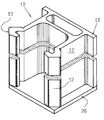
- Fig 1 is a perspective view of a feed beam according to the invention, the guides being not mounted.
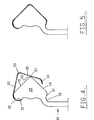
- Fig 2 is a fragmentary end view of a feed beam shown in Fig 1 and it shows a guide while being mounted on the feed beam.
- Fig 3 is an end view corresponding to Fig 2 but it shows the guide mounted on the beam.
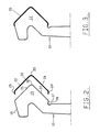
- Figs 4 and 5 correspond to Figs 2 and 3 but they show an alternative design of the feed beam and the guide.
- The feed beam illustrated on the drawings comprises an
extruded die beam 10 of aluminium or a light metal alloy cut in a desired length, usually 3-6 m. Thebeam 10 has a foot plate that formsflanges 11 for mounting the beam on a support. The beam has twoguide beads bead 13, is shown in Figs 2 and 3. Thebead 13 has twosurfaces rounded transition 16 between thesurfaces upper surface 18 on thebead 13 and acorresponding surface 17 in agroove 19 form an acute angle with each other. - A
guide 20 is bent of a flat sheet of spring steel and it has the same form as thebead 13 in order to fit on the latter. Thus, theguide 20 comprises twoguide surfaces rounded part 23. Itsends surfaces surfaces guide 20 is somewhat smaller than the angle between thesurfaces bead 13. The angles between thesurfaces surfaces guide 20 embraces therespective bead guide 20 is forced onto thebead 13, it snaps on and becomes stuck because of its inherent spring characteristics. Its form will coincide with the form of thebead 13 and it will be retained by its edges. Theguide 20 is stiff because of its V-form and it is secured without any screws or the like. The angle between theguiding surfaces - The
guide 20 is a wearing part and it is easy to replace. It can be replaced without the use of any tools because it is snapped in place. Thebeam 10 is symmetrical and a guide is to be snapped onto thebead 12 as well. - In order to prevent water and drill dust from getting under the
guides 20, a sealing agent can be put ontc the respective guide or bead before the guide is mounted. Wax, grease, silicone or similar agents can be used. The agent can be a hardening or non-hardening agent. However, the agent should permit easy removal of the guide. In Figs 4 and 5, an alternative design is shown. Parts corresponding to parts in Figs 1-3 have been given the same reference numerals. The edge of theguide 20 that corresponds toedge 25 in Figs 2 and 3 is formed as acircular hook 30 which mates with a correspondingcircular surface 31 on thebead 13. When theguide 20 is to be mounted, at first thehook 30 is put on thecircular surface 31. Then, the guide 20-is turned into the position of Fig 4 around the hinge formed by thehook 30 and thecircular surface 31. In the position of Fig 4, theguide 20 is held in position by thehook 30. Then, itsedge 24 can be forced onto thesurface 17. The force can be applied to thecentral part 23 which is stiff because it is rounded. Thehook 30 is bent slightly more than a right angle as is thecentral part 23. Theedge 24 is bent less than a right angle but more than 45°. In total, theguide 20 as shown in the figures is bent more than 270° whereas theguide 20 as shown in Figs 2 and 3 is bent more than 180° but less than 270°. - A complete feed beam is not illustrated on the drawings. A feeding device and a cradle for the rock drill (a rotary percussive rock drill or a rotary rock drill) is usually part of a complete feed beam. Sometimes, a cradle is not used but the rock drill can slide directly on the
guides 20. The feeding device can for example comprise one or more hydraulic cylinders which, through a wire rope and pulleys can be coupled to the cradle to pull the latter in both directions along the feed beam. Heads should then be arranged on thebeam 10, which carry the pulleys. If theguides 20 are of the same length as thebeam 10, the end heads can simultaneously form axial supports for the guides. Such anend head 26 is schematically shown in Fig 1. The guides will thus be axially fixed between axial supports that are fixed to thebeam 10.
Claims (7)
characterized i n
that the plate (20) embraces the bead at an angle larger than 270°.
characterized i n that the profiled beam (10) has two guides (20) and each guide (20) has two guiding surfaces (21, 22) at an angle to each other.
characterized in
that the two guiding surfaces (21, 22) are at an angle of 60° - 120° to each other.
characterized in that said angle is between 80° and 100°.
that one edge of the plate is bent as a hook (30) to form with a part (31) of the bead a hinge about which it turns when the other edge (24) of the plate is being snapped onto the bead.
Priority Applications (1)
| Application Number | Priority Date | Filing Date | Title |
|---|---|---|---|
| AT85850136T ATE44304T1 (en) | 1984-04-27 | 1985-04-22 | GUIDE ASSEMBLY FOR A ROCK DRILL. |
Applications Claiming Priority (2)
| Application Number | Priority Date | Filing Date | Title |
|---|---|---|---|
| SE8402315A SE444346C (en) | 1984-04-27 | 1984-04-27 | FEEDBACK FOR MOUNTAIN DRILLING MACHINE RELATED TO A PROFILE BALK |
| SE8402315 | 1984-04-27 |
Publications (3)
| Publication Number | Publication Date |
|---|---|
| EP0159974A2 true EP0159974A2 (en) | 1985-10-30 |
| EP0159974A3 EP0159974A3 (en) | 1987-01-28 |
| EP0159974B1 EP0159974B1 (en) | 1989-06-28 |
Family
ID=20355696
Family Applications (1)
| Application Number | Title | Priority Date | Filing Date |
|---|---|---|---|
| EP85850136A Expired EP0159974B1 (en) | 1984-04-27 | 1985-04-22 | A feed beam for a rock drill |
Country Status (11)
| Country | Link |
|---|---|
| US (1) | US4682899A (en) |
| EP (1) | EP0159974B1 (en) |
| JP (1) | JPH0650034B2 (en) |
| AT (1) | ATE44304T1 (en) |
| AU (1) | AU576118B2 (en) |
| CA (1) | CA1245622A (en) |
| DE (1) | DE3571261D1 (en) |
| FI (1) | FI79883C (en) |
| NO (1) | NO163377C (en) |
| SE (1) | SE444346C (en) |
| ZA (1) | ZA852980B (en) |
Cited By (3)
| Publication number | Priority date | Publication date | Assignee | Title |
|---|---|---|---|---|
| EP1896683A1 (en) * | 2005-06-30 | 2008-03-12 | Atlas Copco Rock Drills AB | Light metal feed beam for use on a drill rig |
| EP3498965A1 (en) * | 2017-12-18 | 2019-06-19 | Sandvik Mining and Construction Oy | Feed beam for rock drilling rig and method of manufacturing the same |
| EP3498966A1 (en) * | 2017-12-18 | 2019-06-19 | Sandvik Mining and Construction Oy | Feed beam and method of stiffening the same |
Families Citing this family (18)
| Publication number | Priority date | Publication date | Assignee | Title |
|---|---|---|---|---|
| GB8805918D0 (en) * | 1988-03-12 | 1988-04-13 | Boart Uk Ltd | Feed beam arrangement for rockdrill |
| JPH05133416A (en) * | 1991-11-07 | 1993-05-28 | Nippon Thompson Co Ltd | Direct-acting guide unit with vibration proofness and manufacture thereof |
| US5213300A (en) * | 1991-12-17 | 1993-05-25 | Itt Corporation | Extruded automotive seat track |
| FI91436C (en) * | 1992-09-24 | 1994-06-27 | Tamrock Oy | Rock drill feed bar |
| DE4311641C1 (en) † | 1993-04-08 | 1994-04-21 | Star Gmbh | Linear motion guide for machinery - has spring belt cover over whole guide top surface locating in recesses in guide sides |
| FI93482C (en) * | 1993-09-03 | 1995-04-10 | Tamrock Oy | Arrangement for installing sliders |
| DE4339541A1 (en) * | 1993-11-19 | 1995-05-24 | Hilti Ag | Guide rail |
| DE9420428U1 (en) * | 1994-12-21 | 1995-02-16 | Schaeffler Waelzlager Kg | Guide rail for a linear bearing |
| FI97420C (en) * | 1995-03-17 | 1996-12-10 | Tamrock Oy | Arrangement in a rock drill feeder beam |
| DE19524810B4 (en) * | 1995-07-07 | 2005-06-16 | Ina-Schaeffler Kg | Arrangement for closing bores in a guide rail |
| US7371009B1 (en) | 2004-06-30 | 2008-05-13 | J.H. Fletcher & Co. | Split gib mounting arrangement for drilling components |
| US20080054238A1 (en) * | 2006-09-01 | 2008-03-06 | R.L. Craig, Inc. | Hoist support post and method of forming same |
| US8132330B2 (en) * | 2007-09-21 | 2012-03-13 | Pacific Bearing Company | Bearing assembly and method of making a bearing assembly |
| US8684605B2 (en) | 2008-03-07 | 2014-04-01 | Pacific Bearing Company | Guide rail |
| US7997351B2 (en) | 2008-05-19 | 2011-08-16 | Longyear Tm, Inc. | Pneumatic drifter with replaceable foot pieces |
| US20100126073A1 (en) * | 2008-11-25 | 2010-05-27 | Pacific Bearing Company | Actuator for elevator doors, elevator door arrangement including same and methods |
| US20100129013A1 (en) * | 2008-11-25 | 2010-05-27 | Pacific Bearing Company | Guide Rail Having Base Rail And Gear Rack, Method Of Making Same, Guide Assembly Including Same |
| JP5331473B2 (en) * | 2008-12-16 | 2013-10-30 | 古河ロックドリル株式会社 | Guide shell for drilling machine |
Citations (2)
| Publication number | Priority date | Publication date | Assignee | Title |
|---|---|---|---|---|
| GB230320A (en) * | 1924-05-28 | 1925-03-12 | John Leonard Holman | Improvements in or relating to cradles for machine tools such as rock drills and the like |
| GB2114027A (en) * | 1982-02-02 | 1983-08-17 | Eimco Secoma | A drilling and bolting turret |
Family Cites Families (5)
| Publication number | Priority date | Publication date | Assignee | Title |
|---|---|---|---|---|
| US2828109A (en) * | 1953-03-12 | 1958-03-25 | Westinghouse Air Brake Co | Drill steel centralizer |
| SE367229B (en) * | 1972-10-06 | 1974-05-20 | Atlas Copco Ab | |
| DE2553549C3 (en) * | 1975-11-28 | 1983-11-03 | Webasto-Werk W. Baier GmbH & Co, 8035 Gauting | Slide shoe for a vehicle sunroof |
| JPS5572912A (en) * | 1978-11-25 | 1980-06-02 | Hiroshi Teramachi | 4-direction equal-load type linear bearing |
| JPS57198128A (en) * | 1981-05-29 | 1982-12-04 | Nissan Motor Co Ltd | Seat-slide device for car |
-
1984
- 1984-04-27 SE SE8402315A patent/SE444346C/en not_active IP Right Cessation
-
1985
- 1985-04-22 AT AT85850136T patent/ATE44304T1/en not_active IP Right Cessation
- 1985-04-22 ZA ZA852980A patent/ZA852980B/en unknown
- 1985-04-22 EP EP85850136A patent/EP0159974B1/en not_active Expired
- 1985-04-22 DE DE8585850136T patent/DE3571261D1/en not_active Expired
- 1985-04-24 CA CA000479910A patent/CA1245622A/en not_active Expired
- 1985-04-25 JP JP60087671A patent/JPH0650034B2/en not_active Expired - Fee Related
- 1985-04-26 NO NO851683A patent/NO163377C/en not_active IP Right Cessation
- 1985-04-26 AU AU41740/85A patent/AU576118B2/en not_active Ceased
- 1985-04-26 FI FI851670A patent/FI79883C/en not_active IP Right Cessation
-
1986
- 1986-05-16 US US06/865,935 patent/US4682899A/en not_active Expired - Lifetime
Patent Citations (2)
| Publication number | Priority date | Publication date | Assignee | Title |
|---|---|---|---|---|
| GB230320A (en) * | 1924-05-28 | 1925-03-12 | John Leonard Holman | Improvements in or relating to cradles for machine tools such as rock drills and the like |
| GB2114027A (en) * | 1982-02-02 | 1983-08-17 | Eimco Secoma | A drilling and bolting turret |
Cited By (7)
| Publication number | Priority date | Publication date | Assignee | Title |
|---|---|---|---|---|
| EP1896683A1 (en) * | 2005-06-30 | 2008-03-12 | Atlas Copco Rock Drills AB | Light metal feed beam for use on a drill rig |
| US8393790B2 (en) | 2005-06-30 | 2013-03-12 | Atlas Copco Rock Drills Ab | Light metal feed beam for use on a drill rig |
| EP1896683A4 (en) * | 2005-06-30 | 2014-07-02 | Atlas Copco Rock Drills Ab | Light metal feed beam for use on a drill rig |
| EP3498965A1 (en) * | 2017-12-18 | 2019-06-19 | Sandvik Mining and Construction Oy | Feed beam for rock drilling rig and method of manufacturing the same |
| EP3498966A1 (en) * | 2017-12-18 | 2019-06-19 | Sandvik Mining and Construction Oy | Feed beam and method of stiffening the same |
| AU2018279051B2 (en) * | 2017-12-18 | 2019-09-19 | Sandvik Mining And Construction Oy | Feed beam and method of manufacturing the same |
| US11053744B2 (en) | 2017-12-18 | 2021-07-06 | Sandvik Mining And Construction Oy | Feed beam and method of manufacturing the same |
Also Published As
| Publication number | Publication date |
|---|---|
| SE444346C (en) | 1987-11-24 |
| SE8402315L (en) | 1985-10-28 |
| NO163377C (en) | 1990-05-16 |
| CA1245622A (en) | 1988-11-29 |
| DE3571261D1 (en) | 1989-08-03 |
| FI851670L (en) | 1985-10-28 |
| FI79883B (en) | 1989-11-30 |
| JPS60233290A (en) | 1985-11-19 |
| ZA852980B (en) | 1985-11-27 |
| AU576118B2 (en) | 1988-08-11 |
| NO851683L (en) | 1985-10-28 |
| FI79883C (en) | 1990-03-12 |
| AU4174085A (en) | 1985-10-31 |
| SE8402315D0 (en) | 1984-04-27 |
| US4682899A (en) | 1987-07-28 |
| FI851670A0 (en) | 1985-04-26 |
| ATE44304T1 (en) | 1989-07-15 |
| EP0159974B1 (en) | 1989-06-28 |
| NO163377B (en) | 1990-02-05 |
| SE444346B (en) | 1986-04-07 |
| JPH0650034B2 (en) | 1994-06-29 |
| EP0159974A3 (en) | 1987-01-28 |
Similar Documents
| Publication | Publication Date | Title |
|---|---|---|
| EP0159974B1 (en) | A feed beam for a rock drill | |
| AU4581789A (en) | Ratchet assembly for a downhole tool | |
| IT8347533A0 (en) | VEHICLE WITH SUPPORT MEANS FOR A FREELY ATTACHABLE WORK TOOL | |
| IT8567419A1 (en) | Bit holder for a tool for hammer drilling. | |
| BE884025A (en) | DOWNHOLE DRILLING TOOL AND METHOD FOR DRILLING A BOREHOLD USING THE SAME | |
| FR2675234B1 (en) | ANTICORROSION SLEEVE FOR PRACTICAL DRILLING IN A METAL PIPE, AND TOOL FOR MOUNTING SUCH SLEEVE. | |
| US3176945A (en) | Adjustable cable straps | |
| TW338739B (en) | A clamping tool for pulling together and clamping spaced apart workpieces | |
| AU5499886A (en) | Metal stamping tool with working parts removable while on the machine | |
| CA2215505C (en) | An arrangement in a feed beam of a rock drill | |
| DE69112348D1 (en) | Wire saws. | |
| WO2006115797A2 (en) | Retainer for cutting bit | |
| IT8322243A0 (en) | TOOL FOR WORKING THE SOIL EQUIPPED WITH A SETTING ROLLER WITH SCRAPERS WITH MULTIPLE INSERTABLE CUTTERS. | |
| US4377213A (en) | Dual bushing centralizer | |
| FR2701801B1 (en) | Hydraulic device for adjustable lightening of the weight of a working tool resting on a plane and application to mobile assemblies with mounted tools. | |
| CN211614391U (en) | Forklift portal positioning die | |
| JP2002285553A (en) | Pile constructing machine | |
| FR2606792B1 (en) | METHOD OF APPLYING A WEAR RESISTANT COATING ON A CUTTING TOOL | |
| JPH0645314Y2 (en) | Scraper for machine tools | |
| FR2584337B1 (en) | TENSIONER FOR DIAMOND CABLE TOOL MACHINE | |
| CN115366267A (en) | Tool for controlling swinging of diamond wire saw during cutting and using method thereof | |
| Elistratov et al. | Increasing Throughput of Bending Tools by Cemented Carbide Coating | |
| ATA352685A (en) | QUICK COUPLING FOR FASTENING THE WORK TOOLS ON AN EXCAVATOR BOOM | |
| DE9309983U1 (en) | Hydraulic drive for work machines, preferably mobile cranes | |
| FR2697190B1 (en) | Robot tool for installing a window regulator. |
Legal Events
| Date | Code | Title | Description |
|---|---|---|---|
| PUAI | Public reference made under article 153(3) epc to a published international application that has entered the european phase |
Free format text: ORIGINAL CODE: 0009012 |
|
| AK | Designated contracting states |
Designated state(s): AT BE CH DE FR GB IT LI LU NL SE |
|
| PUAL | Search report despatched |
Free format text: ORIGINAL CODE: 0009013 |
|
| AK | Designated contracting states |
Kind code of ref document: A3 Designated state(s): AT BE CH DE FR GB IT LI LU NL SE |
|
| 17P | Request for examination filed |
Effective date: 19870629 |
|
| 17Q | First examination report despatched |
Effective date: 19880624 |
|
| ITF | It: translation for a ep patent filed |
Owner name: BARZANO' E ZANARDO ROMA S.P.A. |
|
| GRAA | (expected) grant |
Free format text: ORIGINAL CODE: 0009210 |
|
| AK | Designated contracting states |
Kind code of ref document: B1 Designated state(s): AT BE CH DE FR GB IT LI LU NL SE |
|
| PG25 | Lapsed in a contracting state [announced via postgrant information from national office to epo] |
Ref country code: SE Effective date: 19890628 |
|
| REF | Corresponds to: |
Ref document number: 44304 Country of ref document: AT Date of ref document: 19890715 Kind code of ref document: T |
|
| REF | Corresponds to: |
Ref document number: 3571261 Country of ref document: DE Date of ref document: 19890803 |
|
| ET | Fr: translation filed | ||
| PLBE | No opposition filed within time limit |
Free format text: ORIGINAL CODE: 0009261 |
|
| STAA | Information on the status of an ep patent application or granted ep patent |
Free format text: STATUS: NO OPPOSITION FILED WITHIN TIME LIMIT |
|
| 26N | No opposition filed | ||
| ITTA | It: last paid annual fee | ||
| EPTA | Lu: last paid annual fee | ||
| REG | Reference to a national code |
Ref country code: GB Ref legal event code: IF02 |
|
| PGFP | Annual fee paid to national office [announced via postgrant information from national office to epo] |
Ref country code: FR Payment date: 20020410 Year of fee payment: 18 |
|
| PGFP | Annual fee paid to national office [announced via postgrant information from national office to epo] |
Ref country code: AT Payment date: 20020411 Year of fee payment: 18 |
|
| PGFP | Annual fee paid to national office [announced via postgrant information from national office to epo] |
Ref country code: GB Payment date: 20020417 Year of fee payment: 18 |
|
| PGFP | Annual fee paid to national office [announced via postgrant information from national office to epo] |
Ref country code: LU Payment date: 20020425 Year of fee payment: 18 |
|
| PGFP | Annual fee paid to national office [announced via postgrant information from national office to epo] |
Ref country code: NL Payment date: 20020426 Year of fee payment: 18 |
|
| PGFP | Annual fee paid to national office [announced via postgrant information from national office to epo] |
Ref country code: CH Payment date: 20020430 Year of fee payment: 18 |
|
| PGFP | Annual fee paid to national office [announced via postgrant information from national office to epo] |
Ref country code: DE Payment date: 20020502 Year of fee payment: 18 |
|
| PGFP | Annual fee paid to national office [announced via postgrant information from national office to epo] |
Ref country code: BE Payment date: 20020619 Year of fee payment: 18 |
|
| PG25 | Lapsed in a contracting state [announced via postgrant information from national office to epo] |
Ref country code: LU Free format text: LAPSE BECAUSE OF NON-PAYMENT OF DUE FEES Effective date: 20030422 Ref country code: GB Free format text: LAPSE BECAUSE OF NON-PAYMENT OF DUE FEES Effective date: 20030422 Ref country code: AT Free format text: LAPSE BECAUSE OF NON-PAYMENT OF DUE FEES Effective date: 20030422 |
|
| PG25 | Lapsed in a contracting state [announced via postgrant information from national office to epo] |
Ref country code: LI Free format text: LAPSE BECAUSE OF NON-PAYMENT OF DUE FEES Effective date: 20030430 Ref country code: CH Free format text: LAPSE BECAUSE OF NON-PAYMENT OF DUE FEES Effective date: 20030430 Ref country code: BE Free format text: LAPSE BECAUSE OF NON-PAYMENT OF DUE FEES Effective date: 20030430 |
|
| BERE | Be: lapsed |
Owner name: *ATLAS COPCO A.B. Effective date: 20030430 |
|
| PG25 | Lapsed in a contracting state [announced via postgrant information from national office to epo] |
Ref country code: NL Free format text: LAPSE BECAUSE OF NON-PAYMENT OF DUE FEES Effective date: 20031101 Ref country code: DE Free format text: LAPSE BECAUSE OF NON-PAYMENT OF DUE FEES Effective date: 20031101 |
|
| NLV4 | Nl: lapsed or anulled due to non-payment of the annual fee |
Effective date: 20031101 |
|
| GBPC | Gb: european patent ceased through non-payment of renewal fee |
Effective date: 20030422 |
|
| REG | Reference to a national code |
Ref country code: CH Ref legal event code: PL |
|
| PG25 | Lapsed in a contracting state [announced via postgrant information from national office to epo] |
Ref country code: FR Free format text: LAPSE BECAUSE OF NON-PAYMENT OF DUE FEES Effective date: 20031231 |
|
| REG | Reference to a national code |
Ref country code: FR Ref legal event code: ST |