EP3498920A1 - Garden blower - Google Patents
Garden blower Download PDFInfo
- Publication number
- EP3498920A1 EP3498920A1 EP17838769.2A EP17838769A EP3498920A1 EP 3498920 A1 EP3498920 A1 EP 3498920A1 EP 17838769 A EP17838769 A EP 17838769A EP 3498920 A1 EP3498920 A1 EP 3498920A1
- Authority
- EP
- European Patent Office
- Prior art keywords
- level fan
- level
- fan
- garden blower
- air inlet
- Prior art date
- Legal status (The legal status is an assumption and is not a legal conclusion. Google has not performed a legal analysis and makes no representation as to the accuracy of the status listed.)
- Withdrawn
Links
- 238000007664 blowing Methods 0.000 claims abstract description 134
- 230000002093 peripheral effect Effects 0.000 claims description 14
- 230000000149 penetrating effect Effects 0.000 claims description 3
- 238000010586 diagram Methods 0.000 description 16
- 230000000694 effects Effects 0.000 description 8
- 238000009826 distribution Methods 0.000 description 6
- 230000005540 biological transmission Effects 0.000 description 4
- 230000008859 change Effects 0.000 description 2
- 238000004140 cleaning Methods 0.000 description 2
- 230000009977 dual effect Effects 0.000 description 2
- 230000001788 irregular Effects 0.000 description 2
- 230000009466 transformation Effects 0.000 description 2
- 238000000844 transformation Methods 0.000 description 2
- 230000009471 action Effects 0.000 description 1
- 238000001816 cooling Methods 0.000 description 1
- 230000009189 diving Effects 0.000 description 1
- 239000000428 dust Substances 0.000 description 1
- 238000004519 manufacturing process Methods 0.000 description 1
- 239000000463 material Substances 0.000 description 1
- 238000000034 method Methods 0.000 description 1
- 238000003825 pressing Methods 0.000 description 1
- 230000008569 process Effects 0.000 description 1
- 230000001681 protective effect Effects 0.000 description 1
- 238000010408 sweeping Methods 0.000 description 1
- 210000003813 thumb Anatomy 0.000 description 1
- 238000009966 trimming Methods 0.000 description 1
- 239000002699 waste material Substances 0.000 description 1
- XLYOFNOQVPJJNP-UHFFFAOYSA-N water Substances O XLYOFNOQVPJJNP-UHFFFAOYSA-N 0.000 description 1
- 230000003245 working effect Effects 0.000 description 1
Images



Classifications
-
- F—MECHANICAL ENGINEERING; LIGHTING; HEATING; WEAPONS; BLASTING
- F04—POSITIVE - DISPLACEMENT MACHINES FOR LIQUIDS; PUMPS FOR LIQUIDS OR ELASTIC FLUIDS
- F04D—NON-POSITIVE-DISPLACEMENT PUMPS
- F04D25/00—Pumping installations or systems
- F04D25/02—Units comprising pumps and their driving means
- F04D25/08—Units comprising pumps and their driving means the working fluid being air, e.g. for ventilation
-
- E—FIXED CONSTRUCTIONS
- E01—CONSTRUCTION OF ROADS, RAILWAYS, OR BRIDGES
- E01H—STREET CLEANING; CLEANING OF PERMANENT WAYS; CLEANING BEACHES; DISPERSING OR PREVENTING FOG IN GENERAL CLEANING STREET OR RAILWAY FURNITURE OR TUNNEL WALLS
- E01H1/00—Removing undesirable matter from roads or like surfaces, with or without moistening of the surface
- E01H1/08—Pneumatically dislodging or taking-up undesirable matter or small objects; Drying by heat only or by streams of gas; Cleaning by projecting abrasive particles
-
- E—FIXED CONSTRUCTIONS
- E01—CONSTRUCTION OF ROADS, RAILWAYS, OR BRIDGES
- E01H—STREET CLEANING; CLEANING OF PERMANENT WAYS; CLEANING BEACHES; DISPERSING OR PREVENTING FOG IN GENERAL CLEANING STREET OR RAILWAY FURNITURE OR TUNNEL WALLS
- E01H1/00—Removing undesirable matter from roads or like surfaces, with or without moistening of the surface
- E01H1/08—Pneumatically dislodging or taking-up undesirable matter or small objects; Drying by heat only or by streams of gas; Cleaning by projecting abrasive particles
- E01H1/0809—Loosening or dislodging by blowing ; Drying by means of gas streams
-
- F—MECHANICAL ENGINEERING; LIGHTING; HEATING; WEAPONS; BLASTING
- F04—POSITIVE - DISPLACEMENT MACHINES FOR LIQUIDS; PUMPS FOR LIQUIDS OR ELASTIC FLUIDS
- F04D—NON-POSITIVE-DISPLACEMENT PUMPS
- F04D19/00—Axial-flow pumps
- F04D19/007—Axial-flow pumps multistage fans
Definitions
- the present embodiments relates to a garden blower, and in particular to a fan and an air inlet passage of the garden blower.
- the blower belongs to a conventional electric tool, and is mainly used for blowing falling leaves, dust and accumulated water and snow on the roads and forest fire fighting.
- the user has different requirements on wind power and wind volume under different use environments.
- multilevel fans of the same structure are serially connected to increase the wind power, or the area of an air inlet is increased to improve the wind volume.
- CN patent CN205934814U discloses a handheld axial flow blower, comprising an upper shell, an air outlet cylinder, a motor, ducts and a lower shell, wherein the motor is disposed in the middle of the upper shell and configured to drive the fans to rotate, the lower end of the motor is connected to the lower shell, a plurality of detachable ducts are disposed between the upper shell and the lower shell, the fans in the ducts are connected to the motor, a plurality of bosses a are disposed on the periphery of the side surface of the lower shell, and the upper end of the inner wall of the air outlet cylinder is provided with a plurality of L-shaped grooves corresponding to the bosses a and configured to connect the air outlet cylinder to the lower shell.
- the handheld axial flow blower adopts a multilevel fan design, a level number of the fans can be increased or reduced according to different needs to correspond to different wind volume specifications, there is no need to manufacture a new mould, the use scenarios are greatly expanded, and not only is the blower suitable for blowing garbage, turfgrass clippings and falling leaves as on the lawn as well as the falling leaves of the parks and the roads, but also the strong wind power can be used for the forest fire fighting, road sweeping and snow blowing operation.
- the problem to be solved by the present embodiments is to provide a garden blower, whose blowing efficiency is effectively improved.
- a garden blower comprising: an enclosure, comprising a main body part located on a back end and a blowing pipe located on a front end of the main body part and extending axially, the enclosure being further disposed with an air inlet and an air outlet communicated with an external environment; a power device, connected to the enclosure to provide power for the garden blower; a fan component, driven by the power device to rotate and generating airflows; the fan component comprises at least two-level fans, the at least two-level fans comprise a first-level fan and a second-level fan axially disposed front and back, the garden blower comprises a first air inlet passage allowing entrance of the airflows generated by the first-level fan and a second air inlet passage allowing entrance of the airflows generated by the second-level fan, and the airflows entering the first air inlet passage and the airflows entering the second air inlet passage are converged into the blowing pipe and are blown to the
- the first-level fan is disposed further away from the air outlet compared with the second-level fan, and a sectional area of the first-level fan in a radial direction is smaller than a sectional area of the second-level fan in a radial direction.
- the air inlet comprises a first group of air inlets introducing the airflows into the blowing pipe, when the garden blower is in a working state, the airflows enter the blowing pipe from the first group of air inlets, and the above first air inlet passage is formed between the first group of air inlets and the first-level fan.
- the first group of air inlets comprise an axial air inlet formed in the main body part and a radial air inlet annularly disposed in the main body part in a peripheral direction.
- the air inlet further comprises a second group of air inlets allowing the airflows to enter the blowing pipe, when the garden blower is in a working state, the airflows enter the blowing pipe from the second group of air inlets, and the above second air inlet passage is formed between the second group of air inlets and the second-level fan.
- first group of air inlets and the second group of air inlets are axially separated front and back.
- first group of air inlets and the second group of air inlets are both located in a back side of the fan component.
- At least part of a region of the second air inlet passage is annularly disposed on the periphery of at least part of a region of the first air inlet passage.
- the air flows entering the first air inlet passage are generated by common driving of the first-level fan and the second-level fan, and the airflows entering the second air inlet passage are generated by single driving of the second-level fan.
- the enclosure further comprises a first duct part guiding the airflows into the blowing pipe, and when the garden blower is in the working state, the airflows entering from the first group of air inlets flow into the blowing pipe from the first duct part.
- the first-level fan is disposed in the first duct part, and at least part of a region of the first air inlet passage is formed in an inner cavity defined by the first duct part.
- the first duct part comprises a first interface part penetrating in the axial direction and a second interface part opposite to the first interface part, the first interface part is communicated with the first group of air inlets, the second interface part is disposed between the first-level fan and the second-level fan, and a sectional area of the second interface part in a radial direction is smaller than a sectional area of the second-level fan in a radial direction.
- the enclosure further comprises a second duct part guiding the airflows into the blowing pipe, and when the garden blower is in the working state, the airflows entering from the second group of air inlets flow into the blowing pipe from the second duct part.
- the second-level fan is disposed in the second duct part, and at least part of a region of the second air inlet passage is formed between an inner wall of the second duct part and an outer wall of the first duct part.
- a front end of the first duct part and the second-level fan are axially disposed with an interval.
- At least part of the airflows entering the first air inlet passage and at least part of the airflows entering the second air inlet passage are converged between the first-level fan and the second-level fan, and blown into the blowing pipe from the second-level fan.
- first-level fan and the second-level fan comprise a hub and a plurality of blades disposed around the hub in a peripheral direction, and at least one of the number of the blades, a rotary outer diameter of the blades and a rotary inner diameter of the blades of the first-level fan is different from the number of the blades, a rotary outer diameter of the blades and a rotary inner diameter of the blades of the corresponding second-level fan.
- the absolute value range of a difference value between the rotary outer diameter of the first-level fan and the rotary outer diameter of the second-level fan is 10mm-90mm.
- a difference value absolute value between the rotary inner diameter of the blades of the first-level fan and the rotary inner diameter of the blades of the second-level fan is smaller than or equal to 50mm.
- a hub ratio of the first-level fan is 0.55-0.85, and a hub ratio of the second-level fan is 0.5-0.8.
- the difference between the number of the blades of the first-level fan and the number of the blades of the second-level fan is 1-9.
- the garden blower comprises a first-level guide blade corresponding to the first-level fan and a second-level guide blade corresponding to the second-level fan, the first-level fan and the second-level fan both have an air inlet side and an air outlet side, the first-level guide blade is located on the air outlet side of the first-level fan and the second-level guide blade is located on the air outlet side of the second-level fan.
- a preset clearance exists between the first-level fan and the first-level guide blade and between the second-level fan and the second-level guide blade, and a size range of the preset clearance in an axial direction is 3mm-12mm.
- a wind speed of the garden blower is 50-150mph
- a wind volume of the garden blower is 250-800cfm.
- the power device comprises a motor and a control circuit, the motor controls rotational motion of the fan component, a rotary speed of the motor is larger than or equal to 8000 revolutions/min and smaller than or equal to 25000 revolutions/min, a rotary outer diameter of the first-level fan is 40mm-80mm, and a rotary outer diameter of the second-level fan is 70mm-130mm.
- the power device comprises a motor and a control circuit, the motor controls rotational motion of the fan component, a rotary speed of the motor is larger than or equal to 25000 revolutions/min and smaller than or equal to 100000 revolutions/min, a rotary outer diameter of the first-level fan is 20mm-50mm, and a rotary outer diameter of the second-level fan is 30mm-70mm.
- the blowing pipe is disposed with a central axis axially
- the motor drives the first-level fan and the second-level fan to rotate around a rotational axis
- the first-level fan and the second-level fan are coaxially disposed and have a rotary axis driven by the motor to rotate
- the central axis of the blowing pipe, the rotational axis of the motor and the rotary axis of the first-level fan and the second-level fan are coincided.
- the number of the first-level fan is larger than or equal to 1, and the number of the second-level fan is larger than or equal to 1.
- first-level fan and the second-level fan are both an axial flow fan.
- the at least two-level fans comprise a third level fan, and the number of the blades or a rotary outer diameter of the blades or a rotary inner diameter of the blades of at least one level fan in the first-level fan, the second-level fan and the third level fan are different from the other two-level fans.
- the problem to be solved by the present embodiments is to provide a garden blower, whose blowing efficiency is effectively improved.
- a garden blower comprising: an enclosure, comprising a main body part located on a back end and a blowing pipe located on a front end of the main body part and extending axially, the enclosure being further disposed with an air inlet and an air outlet communicated with an external environment; a power device, connected to the enclosure to provide power for the garden blower; a fan component, driven by the power device to rotate and generating airflows; the fan component comprises at least two-level fans, the at least two-level fans comprise a first-level fan and a second-level fan axially disposed front and back, the first-level fan and the second-level fan both comprise a hub and a plurality of blades disposed around the hub in a peripheral direction, and at least one of a rotary outer diameter of the blades, a rotary inner diameter of the blades, the number of the blade and a dip angle of the blades of the first-level fan is different from the second-level fan
- first-level fan is disposed further away from the air outlet compared with the second-level fan, and the first-level fan and the second-level fan are both of an axial flow fan.
- the power device can drive the first-level fan and the second-level fan to rotate, at least part of the airflows generated by rotation of the first-level fan and the second-level fan enters the blowing pipe from the air inlet, and an independent air inlet passage is formed between the air inlet and the air outlet.
- a ratio range between a shaft power of the first-level fan and a shaft power of the second-level fan is 1.05:1-2.5:1.
- the blades of the first-level fan rotate to form a first annular rotary surface
- the blades of the second-level fan rotate to form a second annular rotary surface
- a sectional area of the second annular rotary surface in a radial direction is smaller than a sectional area of the first annular rotary surface in a radial direction.
- a clearance between edges of the blades of the first-level fan and an inner wall of the enclosure of the first-level fan is larger than or equal to a clearance between edges of the blades of the second-level fan and an inner wall of the enclosure of the second-level fan.
- the air inlet comprises a first group of air inlets introducing the airflows into the blowing pipe, when the garden blower is in a working state, the airflows enter the blowing pipe from the first group of air inlets, and the above first air inlet passage is formed between the first group of air inlets and the first-level fan.
- the first groups of air inlets comprise an axial air inlet formed in the main body part and a radial air inlet annularly disposed in the main body part in a peripheral direction.
- the air inlet further comprises a second group of air inlets introducing the airflows into the blowing pipe, when the garden blower is in a working state, the airflows enter the blowing pipe from the second group of air inlets, and the above second air inlet passage is formed between the second group of air inlets and the second-level fan.
- At least part of the airflows entering the first air inlet passage and at least part of the airflows entering the second air inlet passage are converged between the first-level fan and the second-level fan, and blown into the blowing pipe from the second-level fan.
- first group of air inlets and the second group of air inlets are axially separated front and back.
- the blades of the first-level fan rotate to form a first annular rotary surface
- the blades of the second-level fan rotate to form a second annular rotary surface
- a sectional area of the second annular rotary surface in a radial direction is larger than a sectional area of the first annular rotary surface in a radial direction.
- a hub ratio of the first-level fan is 0.55-0.85.
- a hub ratio of the second-level fan is 0.5-0.8.
- a dip angle of the first-level fan is different from a dip angle of the second-level fan.
- the difference between the number of the blades of the first-level fan and the number of the blades of the second-level fan is 1-9.
- the absolute value range of a difference value between the rotary outer diameter of the blades of the first-level fan and the rotary outer diameter of the blades of the second-level fan is 10mm-90mm.
- a difference value absolute value between the rotary inner diameter of the blades of the first-level fan and the rotary inner diameter of the blades of the second-level fan is smaller than or equal to 50mm.
- the garden blower comprises a first-level guide blade corresponding to the first-level fan and a second-level guide blade corresponding to the second-level fan, the first-level fan and the second-level fan both have an air inlet side and an air outlet side, the first-level guide blade is located on the air outlet side of the first-level fan and the second-level guide blade is located on the air outlet side of the second-level fan.
- a preset clearance exists between the first-level fan and the first-level guide blade and between the second-level fan and the second-level guide blade, and a size range of the preset clearance in an axial direction is 3mm-12mm.
- the power device comprises a motor and a control circuit, the motor controls rotational motion of the fan component, and the power device and the enclosure are detachably mounted.
- the blowing pipe is disposed with a central axis axially
- the first-level fan and the second-level fan are coaxially disposed and have a rotary axis driven by the motor to rotate
- the motor drives the first-level fan and the second-level fan to rotate around a rotational axis
- the central axis of the blowing pipe, the rotational axis of the motor and the rotary axis of the first-level fan and the second-level fan are coincided.
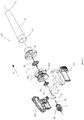
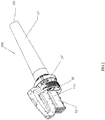
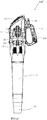
- Figs. 1 to 14 show structural schematic diagrams of garden blowers 100,100' disclosed by the present embodiments, and the garden blowers 100,100' are common garden tools and used for executing cleaning work.
- the garden blowers 100,100' mainly use a blowing function to collect scattered leaves, thereby achieving the purpose of cleaning.
- the garden blower can be understood as a single-blowing garden blower, and can also be understood as a blowing and sucking machine having both a blowing function and an air sucking function.
- the garden blowers 100,100' integrally extend along a direction as shown by an arrow B in Fig. 1 and such direction is defined as the axial direction.
- the garden blower comprises an enclosure 10, a power device 20 and a fan component 30.
- the enclosure 10 comprises a main body part 11 located on a back end and a blowing pipe 13 located on a front end and extending axially, as well as an air inlet 14 and an air outlet 131 communicated with an external environment and an inner cavity of the blowing pipe 13.
- the enclosure 10 can play a role ofprotection, and the fan component 30 and the power deice 20 are both mounted in the enclosure 10, thereby ensuring operation safety when a user uses the garden blower 100, and avoiding the contact with the fan component 30 or other parts.
- the power device 20 is connected to the main body part 11 to provide power for the garden blower 100.
- the power device 20 comprises a motor 2 capable of diving the fan component 30 to rotate around a rotational axis, and the motor 2 is contained in the main body part 11.
- the power device 20 is detachably connected to the enclosure 10, such that when the garden blower 100 is idle, the power device 20 can be detached to be used for other electric tools, and resource waste can be reduced.
- the blowing pipe 13 approximately extends along a central axis X, and is hollow internally, configured to provide air circulation, and convenient for blowing the air to a boundary from the blowing pipe 13. It is defined that the blowing pipe 13 is located on the axial front end of the main body part 11, and then the other end opposite to the axial front end can be understood as the axial back end.
- the blowing pipe 13 comprises a connecting port 133 located in the axial back end, and the above air outlet 131 is located in the axial front end of the blowing pipe 13.
- the power device 20 drives the fan component 30 to rotate to introduce external airflows into the blowing pipe 13 and the external airflows are outward blown from the air outlet 131 of the blowing pipe 13.
- the blowing pipe 13 can be formed by combining a plurality of pipes and having a complete blowing function.
- the fan component 30 is contained in the enclosure 10 and comprises at least two-level fans, and the at least two-level fans comprise a first-level fan 31 and a second-level fan 33 axially disposed front and back.
- the first-level fan 31 and the second-level fan 33 are coaxially disposed and have a rotary axis driven by the motor 2 to rotate.
- the rotational axis of the motor 2, the central axis X of the blowing pipe, and the rotary axis of the first-level fan 31 and the second-level fan 33 are coincided, relative to a single-level fan, the arrangement of the multilevel fans will bring about a design limitation of higher noise, while the noise of the whole set can be greatly reduced by coinciding the above three axes, and the blowing efficiency is better.
- the first-level fan 31 and the second-level fan 33 are both an axial flow fan. Since the axial flow fan can generate higher wind speed, the blowing efficiency can be greatly improved without increasing a size of the fans.
- a working effect of the garden blower mainly depends on a blowing volume and a blowing speed of the garden blower 1
- the blowing volume and the blowing speed of the garden blower are mainly decided by a blowing effect of the fan component 30 as well as structures of the enclosure 10 and the blowing pipe 13, while the blowing effect of the fan component 30 is mainly decided by wind pressures and wind volumes of the at least two-level fans.
- the wind volume of the fan component 30 is the air volume discharged by the fan component in unit time.
- the wind pressure of the fan component 30 is a difference between the total pressure of outlet airflows and the total pressure of inlet airflows of the fan component 30.
- the single-blowing blower usually adopts the fans of the same structure to act on the air to achieve the purpose of high wind pressure.
- the inventors found that the structures of all levels of fans are the same, the shaft power of two-level or multilevel fans is close, and the pressurizing of the inter-level fans is close relatively, as a result, the multilevel fans of the same structure in the current single-blowing blower cannot play the role of pressurizing very well.
- the expected blowing efficiency is not realized compared with the single-level fan.
- the current dual-level or multilevel single-blowing blower has the condition that wet leaves cannot be moved by blowing or the blowing efficiency is low when in use, and the better blowing effect cannot be achieved.
- the structure of the first-level fan 31 is designed to be different from the structure of the second-level fan 33.
- the first-level fan 31 and the second-level fan 33 comprise a hub 32 and a plurality of blades 34 disposed around the hub in a peripheral direction.
- a rotary outer diameter of the blades, a rotary inner diameter of the blades, the number of the blades, and a dip angle of the blades of the first-level fan 31 is different from the second-level fan.
- the level number of the fan is not limited to two, but in the present embodiment, the two-level fans are taken as an example for explanation.
- the number of the first-level fan 31 may be 1 or more than 1, and the structures of respective first-level fans 31 may be totally same or at least partially different.
- the number of the second-level fan 33 may be 1 or more than 1, and the structures of respective second-level fans 33 may be totally same or at least partially different.
- the two-level fans are taken as an example to introduce that the structure of at least one level fan in the multilevel fans is different from other levels of fans in which means.
- the blades of the fan have a wing-shaped inner chord, and an included angle between the wing-shaped inner chord and the horizontal line (frontal line) is the tip angle of the fan. That is to say, one or several or all of the four quantities (i.e., the rotary outer diameter, the rotary inner diameter, the number of the blades and the dip angle of the blades) can be changed to realize that the structure of the first-level fan 31 is different from the structure of the second-level fan 33. Specifically, examples are illustrated one by one for explanation as follows.
- the absolute value range of a difference value between the rotary outer diameter of the first-level fan 31 and the rotary outer diameter of the second-level fan 33 is 10mm-90mm.
- the absolute value of the difference value may be 10mm, 15mm, 20mm, 25mm, 35mm, 40mm, 45mm, 50mm, 55 mm, 60 mm, 65 mm, 70 mm, 80 mm and 90 mm.
- the absolute value range of a difference value between the rotary outer diameter of the first-level fan 31 and the rotary outer diameter of the second-level fan 33 is 10mm-50mm.
- a rotary outer diameter of the first-level fan 31 is larger than a rotary outer diameter of the second-level fan 33, 30mm is taken as an example of the absolute value of the difference value between the rotary outer diameter of the blades of the first-level fan 31 and the rotary outer diameter of the blades of the second-level fan 33 for explanation, the rotary outer diameter of the blades of the first-level fan 31 is 110mm, and the rotary outer diameter of the blades of the second-level fan 33 is 80mm.
- the rotary outer diameter of the blades of the first-level fan is 40mm-80mm, and the rotary outer diameter of the blades of the second-level fan is 70mm-130mm.
- 25mm is taken as an example of the absolute value of the difference value between the rotary outer diameter of the blades of the first-level fan 31 and the rotary outer diameter of the blades of the second-level fan 33 for explanation, the rotary outer diameter of the blades of the first-level fan 31 is 70mm, and the rotary outer diameter of the blades of the second-level fan 33 is 95mm.
- the absolute value of the difference value between the rotary inner diameter of the blades of the first-level fan 31 and the rotary inner diameter of the blades of the second-level fan 33 is smaller than or equal to 50mm.
- the absolute value of the difference value can be 0mm, 5mm, 10mm, 15mm, 20mm, 25mm, 30mm, 35mm, 40mm, 45mm and 50mm.
- the absolute value of the difference value between the rotary inner diameter of the blades of the first-level fan 31 and the rotary inner diameter of the blades of the second-level fan 33 is 1mm-14mm.
- the rotary inner diameter of the first-level fan 31 is larger than the rotary inner diameter of the second-level fan 33, and 5mm is taken as an example of the absolute value of the difference value between the rotary inner diameter of the blades of the first-level fan 31 and the rotary inner diameter of the blades of the second-level fan 33 for explanation, the rotary inner diameter of the first-level fan 31 can be designed to be 50mm, and the rotary inner diameter of the second-level fan 33 can be designed to be 55mm.
- the rotary inner diameter of the first-level fan is 15mm-75mm; and the rotary inner diameter of the second-level fan is 30mm-100mm.
- the rotary inner diameter of the 31 is smaller than the rotary inner diameter of the 33, and 5mm is taken as an example of the absolute value of the difference value between the rotary inner diameter of the blades of the first-level fan 31 and the rotary inner diameter of the blades of the second-level fan 33 for explanation.
- the rotary inner diameter of the first-level fan 31 can be designed to be 50mm, and the rotary inner diameter of the second-level fan 33 can be designed to be 55mm.
- the difference between the number of the blades of the first-level fan 31 and the number of the blades of the second-level fan 33 is 1-9.
- 3 is taken as an example of the difference between the number of the blades of the first-level fan 31 and the number of the blades of the second-level fan 33 for explanation.
- the number of the blades of the first-level fan 31 being larger than the number of the blades of the second-level fan 33 is taken as an example for explanation, the number of the blades of the first-level fan 31 is 11, and the number of the blades of the second-level fan 33 is 8.
- the number of the blades of the first-level fan 31 is 9, and the number of the blades of the second-level fan 33 is 12.
- the dip angle of the blades of the first-level fan 31 is different from the dip angle of the blades of the second-level fan 33.
- the absolute value of the difference value between the dip angle of the blades of the first-level fan 31 and the dip angle of the blades of the second-level fan 33 is 1-10 degrees.
- 3 degrees is taken as the difference between the dip angle of the blades of the first-level fan 31 and the dip angle of the blades of the second-level fan 33 for explanation.
- the dip angle of the blades of the first-level fan 31 being larger than the dip angle of the blades of the second-level fan 33 is taken as an example for explanation, the dip angle of the blades of the first-level fan 31 is 30 degrees, and the dip angle of the blades of the second-level fan 33 is 27 degrees.
- the dip angle of the blades of the first-level fan 31 is 25 degrees, and the dip angle of the blades of the second-level fan 33 is 28 degrees.
- first-level fan 31 and second-level fan 33 both have an air inlet side and an air outlet side, and the air inlet sides of the first-level fan 31 and the second-level fan 33 face the same direction, and are set to face the air inlet 14.
- An arrangement manner of the first-level fan 31 and the second-level fan 33 is: the air inlet side of the first-level fan 31 is set to face the air inlet 14, and the air inlet side of the second-level fan 33 corresponds to the air outlet side of the first-level fan 31.
- the garden blower further comprises at least one level guide blade 15.
- the guide blade 15 can be disposed on the air outlet side of the fan component 30 (as shown in Fig. 13 ), and can also be disposed on one end of the air outlet side of each level fan (as shown in Figs. 11 , 12 and 14 ).
- Each level fan rotates during working to realize the pressurizing and boosting of the airflows; the guide blade 15 is motionless, the airflows output by the air outlet side are guided by the guide blade 15 to flow, such that the noise generated by the impact between the airflows and the enclosure is reduced, and the comfort level of the user during use is improved.
- the guide blade 15 can also avoid turbulence of the airflows, ensures stable flowing of the airflows, and further ensures air outlet stability and a blowing effect.
- the fan component 30 comprises two-level fans.
- the level number of the guide blade 15 is one level.
- the first-level fan 31 and the second-level fan 33 are driven by the motor 2 to rotate, and the guide blade 15 is not disposed between the air outlet side of the first-level fan 31 and the air inlet side of the second-level fan 33, and is only disposed on the air outlet side of the second-level fans 33.
- the fan component 30 comprises two-level fans, and the level number of the guide blades is also two. That is, the level number of the guide blades is consistent with that of the fans.
- the air outlet side of the first-level fan 31 is correspondingly disposed with a first-level guide blade 151
- the air outlet side of the second-level fan 33 is correspondingly disposed with a second-level guide blade 153.
- the difference between the number of the first-level guide blades 151 and the number of the second-level guide blades 153 is 1-9.
- the number of the first-level guide blades 151 is 3, and the number of the second-level guide blades 153 is 6.
- the number of the first-level guide blades 151 may also be same as the number of the second-level guide blades 153.
- the garden blower is further disposed with a handle 16 for holding, and the handle is approximately shaped like a reverse C.
- the two ends are connected to the enclosure 10 respectively, thereby forming a holding space.
- the handle 16 can be integrally disposed with the enclosure 10, and may also be separately disposed with the enclosure 10.
- the handle 16 is located above the garden blower.
- the handle is located above the motor 2, and in this way, the handle 16 and the motor 2 can achieve relative ideal weight balance.
- the handle 16 is provided with an operating switch 161 for starting and closing the garden blower.
- the operating switch 161 may be a push button structure, and may also be in other shapes such as a columnar button, the operating switch 161 may be disposed above the handle 16, and when the operator holds the handle 16, the thumb of the operator can just touch and start the operating switch 161.
- the operating switch 161 may also be located on the inner side of the handle 16, such that the operator can conveniently finish the action of pressing the operating switch when holding the handle, thereby realizing fast starting or closing of the machine.
- the garden blower 100 rotates by the multilevel fans to generate the airflows.
- the two-level fans as an example for explanation, that is, the first-level fan 31 and the second-level fan 33, wherein the first-level fan 31 is disposed further away from the air outlet 131 compared with the second-level fan 33.
- the garden blower 100 has two air inlet passages matched with the first-level fan 31 and the second-level fan 33 rather than only having the independent single-air inlet passage.
- the structure of the present embodiment is introduced in detail as follows.
- the main body part 11 and the blowing pipe 13 are disposed separately, and of course, the main body part 11 and the blowing pipe 13 may also be formed integrally.
- the main body part 11 is formed by assembling two half shells.
- the main body part 40 comprises a left enclosure 111 and a right enclosure 113. After the left enclosure 111 and the right enclosure 113 are combined, a containing part 115 containing the motor 2 therein and an annular body part 117 forward extending from the containing part are formed.
- a sectional area of the annular body part 117 in a radial direction is larger than that of the containing part 115 in the radial direction.
- the air inlet 14 comprises a first group of air inlets 141 and a second group of air inlets 143 for introducing the airflows into the blowing pipe 13.
- the first group of air inlets 141 and the second group of air inlets 143 are both located in the back side of the fan component 30.
- the first group of air inlets 141 is located in the back side of the first-level fan 31 and the second-level fan 33.
- the second group of air inlets 143 is also located in the back side of the first-level fan 31 and the second-level fan 33.
- the multiple groups of air inlets 14 are disposed to ensure the increased air inlet volume.
- the first group of air inlets 141 and the second group of air inlets 143 are separately and axially disposed front and back.
- the second group of air inlets 143 is located in an axial front end
- the first group of air inlets 141 is located in an axial back end.
- an operation direction and an operation position of the first group of air inlets 141 are not single.
- the first group of air inlets 141 comprises an axial air inlet 1411 formed in the main body part 11 and a radial air inlet 1413 annularly disposed in the peripheral direction of the main body part 11.
- the axial air inlet 1411 comprises a first axial air inlet 1415 formed in the containing part 115, and a second axial air inlet 1417 formed in the annular body part 117.
- the second axial air inlet 1417 is closer to the first-level fan 31 compared with the first axial air inlet 1415.
- the first axial air inlet 1415 is located right behind the motor 2, and therefore, the airflows entering the first axial air inlet 1415 not only are used for outward blowing to sweep the leaves, but also can serve as cooling airflows to directly cool the motor 2.
- the first axial air inlet 1415 here can also be understood as a radiating port.
- the radial air inlet 1413 comprises a first radial air inlet 1412 located in the annular body part 117 and extending axially, and a second radial air inlet 1414 located in the annular body part 117 and extending radially.
- At least part of the airflows entering the first air inlet passage and at least part of the airflows entering the second air inlet passage are converged between the first-level fan 31 and the second-level fan 33, and are blown into the blowing pipe from the second-level fan 33.
- at least part of the second air inlet passage is annularly disposed on the periphery of at least part of a region of the first air inlet passage.
- the garden blower 100 further comprises a first duct part 17 guiding the airflows into the blowing pipe 13, and the first duct part 17 is located between the axial air inlet 1411 and the second-level fan 33.
- the first-level fan 31 is disposed in the first duct part 17, and at least part of the first air inlet passage is formed in an inner cavity defined by the first duct part 17.
- the first duct part 17 in the present embodiment is a cylindrical part, and is approximately shaped like a desk lamp.
- the first duct part 17 comprises a first interface part 171 penetrating in the axial direction and a second interface part 173 opposite to the first interface part 171.
- the first interface part 171 is communicated with the first group of air inlets 141
- the second interface part 173 is disposed between the first-level fan 31 and the second-level fan 33, and a sectional area of the second interface part 173 in a radial direction is smaller than a sectional area of the second-level fan 33 in a radial direction. That is, an opening size of the interface part is set to be small in the front and big in the back, and the airflows can be pressurized to certain extent in the first duct part 17.
- the back end of the first duct part 17 is fixedly connected to the main body part 11. Specifically, as shown in Figs. 1 and 3 , a vertical symmetric surface of the first duct part 17 is provided with a limiting bulge 175 to limit the first duct part 17 to rotate in a peripheral direction relative to the main body part 11.
- the garden blower 100 further comprises a second duct part 18 guiding the airflows into the blowing pipe 13.
- the airflows entering from the second group of air inlets 143 flow into the blowing pipe 13 from the second duct part 18.
- the second-level fan 33 is disposed in the second duct part 18, and at least part of the second air inlet passage is formed between an inner wall of the second duct part 18 and an outer wall of the first duct part 17.
- the second duct part 18 comprises a front guide cone 181 disposed between the fan component 30 and the air outlet 131.
- the sectional area of the front guide cone 181 in a direction vertical to the central axis X is gradually reduced from the axial back end to the axial front end.
- the front guide cone 181 is an internally hollow structure.
- the sectional area of the blowing pipe in a direction vertical to the central axis X is reduced, thereby obtaining the air outlet airflows of a higher speed.
- the blowing pipe 13 sleeves the front end of the second duct part 18, and is detachably connected to the second duct part 18.
- At least part of the airflows generated by single driving of the second-level fan 33 flows into the second duct part 18 from the second group of air inlets 143, and then enters the blowing pipe 13.
- At least part of the second duct part 18 is at least partially annularly disposed on the periphery of the first duct part 17.
- the first duct part 17 and the second duct part 18 are fixedly connected in a mode that a clamping pin and a clamping groove as shown in Figs. 6 and 7 are matched and connected.
- the front end of the first duct part 17 is disposed with the clamping pin 176 radially bulged along the first duct part 17.
- the second duct part 18 is disposed with the clamping groove 183 matched with the clamping pin 176, and the first duct part 17 and the second duct part 18 are fixed by clamping the clamping pin 176 into the clamping groove 183.
- a boss 184 is disposed on the inner side of the clamping groove 183, the clamping pin 176 and the boss 184 are disposed with a threaded hole 185 respectively, and tightly connection between the first duct part 17 and the second duct part 18 is realized by threaded connection between screws and the threaded holes 185.
- the first duct part 17 and the second duct part 18 are connected between the blowing pipe 13 and the main body part 11.
- the second duct part 18 may not be disposed as long as the second group of air inlets 143 allowing the airflows to enter the second air inlet passage is formed between the blowing pipe 13 and the first duct part 17, and the airflows entering from the second group of air inlets 143 may directly flow into the blowing pipe 13.
- the number of the duct parts may not be limited to two, and the specific amount can be correspondingly adjusted according to a fan level number or the number of the air inlet passages.
- the first duct part 17, the second duct part 18, the main body part 11 and the blowing pipe 13 are disposed in a splitting manner. While in other embodiments, at least two of the first duct part 17, the second duct part 18, the main body part 11 and the blowing pipe 13 are integrally formed or all of them are integrally formed.
- the garden blower 100 further comprises a plurality of flow guide plates 1431 for guiding the airflows entering the second group of air inlets 143.
- the flow guide plates 1431 are disposed between an outer peripheral surface of the first duct part 17 and an inner peripheral surface of the second duct part 18 and are equidistantly disposed in the peripheral direction at an interval.
- the flow guide plates 1413 are disposed to guide a flowing direction of the airflows entering the second group of air inlets 143, that is, the airflows are enabled to forward axially move into the blowing pipe 13 in the second air inlet passage along the flow guide plates 1431, loss of the airflows is reduced, and air output is increased.
- the size of the first-level fan 31 is different from the size of the second-level fan 33. Specifically, a sectional area of the first-level fan 31 in a radial direction is smaller than a sectional area of the second-level fan 33 in a radial direction. A shaft power of the first-level fan 31 is smaller than a shaft power of the second-level fan 33. Further, a ratio of the shaft power of the first-level fan 31 to the shaft power of the second-level fan 33 is 1:2.5-1:1.05.
- the rotary outer diameter of the second-level fan 33 is larger than the rotary outer diameter of the first-level fan 31. Further, when the rotary speed of the motor 2 is larger than or equal to 12000 revolutions/minute, and smaller than or equal to 25000 revolutions/min, the rotary outer diameter of the first-level fan 31 is 40mm-80mm, and the rotary outer diameter of the second-level fan is 70mm-130mm. When the rotary speed of the motor is larger than 25000 revolutions/min and smaller than or equal to 100000 revolutions/min, Further, the rotary outer diameter of the first-level fan 31 is 20mm-50mm, and the rotary outer diameter of the second-level fan 33 is 30mm-70mm.
- the rotary inner diameter of the second-level fan 33 is larger than the rotary inner diameter of the first-level fan 31.
- the blades of the first-level fan 31 rotate to form a first annular rotary surface
- the blades of the second-level fan 33 rotate to form a second annular rotary surface.
- the sectional area of the first annular rotary surface in a radial direction is smaller than the sectional area of the second annular rotary surface in a radial direction.
- D 1 is the rotary outer diameter of the first-level fan
- D 2 is the hub diameter of the first-level fan 33
- D 3 is the rotary outer diameter of the second-level fan
- D 4 is the hub diameter of the second-level fan 33
- Sa is smaller than S b .
- a total air inlet area formed by the first group of air inlets 141 and the second group of air inlets 143 is defined as an air inlet area.
- the area of the air outlet of the air outlet 131 of the blowing pipe 13 is defined as the air outlet area.
- the air inlet area:Sa:air outlet area equals to (2-2.7):1:(0.85-1), and meanwhile, the air inlet area:Sb:air outlet area equals to (2-2.7):1:(0.85-1). Under such ratios, the blowing efficiency of the two-level fan dual-air inlet passage axial flow garden blower 100 is higher.
- a hub ratio of the first-level fan 31 is 0.55-0.85, and a hub ratio of the second-level fan 33 is 0.5-0.8. Further, the hub ratio of the first-level fan 33 is larger than the hub ratio of the second-level fan 31, the hub ratio of the first-level fan 31 is 0.65 Further, and the hub ratio of the second-level fan 33 is 0.55 Further. It should be noted that a root diameter of the blade 34 is the rotary inner diameter, and a top diameter of the blade 34 is the rotary outer diameter. The ratio of the hub diameter to the top diameter of the blade is the hub ratio well known by those skilled in the art.
- the hub ratios of the first-level fan 31 and the second-level fan 33 are very important to the wind volume and wind speed of the garden blower 100.
- the hub ratio directly affects the matching between the wind volume and the wind speed, thereby ensuring the blowing efficiency of the axial flow garden blower.
- a transmission shaft 19 is further disposed between the motor 2 and the first-level fan 31 and the second-level fan 33.
- the motor 2 comprises an output shaft 31 outputting power, and the output shaft 31 drives the first-level fan 31 and the second-level fan 33 to rotate together by the transmission shaft 19 around a rotary axis.
- the first-level fan 31 and the second-level fan 33 synchronously operate at the same speed, but as an alternative embodiment, the first-level fan 31 and the second-level fan 33 may also synchronously operate at different speeds, or asynchronously operate at the same speed or asynchronously operate at different speeds.
- an output shaft 21 of the motor 2 may be connected to the transmission shaft 19 by a connecting shaft bush 23, and the end part of the connecting shaft bush 23 is fixed and limited by a clamping ring 25.
- the connecting shaft bush 23 is disposed with a back guide cone 27; and the transmission shaft 19 penetrates through the first duct part 17 to extend into the second duct part 18.
- the motor 2 drives the first-level fan 31 and the second-level fan 33 to together drive external airflows to flow into the first duct part 17 from the first group of air inlets 141, at this point, a first air inlet passage is formed between the first group of air inlets 141 and the first-level fan 31, the flow flowing into the first air inlet passage is taken as Q1, and the wind pressure formed by the airflows in the first air inlet passage is taken as PI.
- At least part of the airflows generated by rotation of the second-level fan 33 enters the second duct part 18 to form a second air inlet passage between the second group of air inlets 143 and the second-level fan 33, the flow flowing into the second air inlet passage is taken as Q2, and the wind pressure formed by the airflows in the second air inlet passage is taken as P2.
- the airflows flowing into the first air inlet passage and the airflows flowing into the second air inlet passage are converged into the blowing pipe 13, that is, a mixing flow path is formed in the blowing pipe 13, and finally strong jetting airflows are formed in the air outlet 131 of the blowing pipe 13.
- the wind volume Q flowing into the blowing pipe 13 equals to Q1+Q2, and the wind volume is improved greatly.
- the wind pressure P generated by the airflows flowing into the blowing pipe 13 equals to P1+P2. Due to the front guide cone 28, the wind pressure finally formed by the airflows on the front end of the blowing pipe 13 can be larger. Therefore, the flow rate of the airflows blown from the air outlet 191 of the bowing pipe 19 is obviously increased. Further, when the garden blower 100 is in the working state, the wind speed of the garden blower is 50-140mph, and the wind volume of the garden blower is 250-800cfm.
- the garden blower 100 provided by the present embodiment, it is ensured that the wind volume is obviously increased while the wind speed is considered, and due to the provided wind speed and wind volume, the garden blower can be used under different working conditions, which all have a very good blowing effect.
- the increase of the wind volume and wind speed of the multilevel fan multi-air passage axial flow garden blower provided by the embodiment will be presented by comparing with the related parameters of a conventional axial flow garden blower.
- Fig. 8 shows a schematic diagram of wind pressure distribution of a conventional single-level fan single-air passage axial flow garden blower
- Fig. 9 shows a schematic diagram of wind pressure distribution of a two-level fan single-air passage axial flow garden blower, and here, the two-level fans are same in structure, and the Fig. 9 merely purely from Fig. 8 in fan superposing.
- Fig. 10 is a schematic diagram of wind pressure distribution of a two-level fan dual-air inlet passage axial flow garden blower of the present embodiments.
- the unit of vertical axis data in Fig. 10 is pa, and represents the wind pressure of the blowing pipe in the air outlet. It is known from the following table that if the fans are purely superposed in the air passage, the pressure in the air passage is increased but the wind volume is reduced.
- the air inlet passages are superposed, the fan for introducing the airflows into each air inlet passage is disposed in each air inlet passage, and the first-level fan 31 and the second-level fan 33 are different in structure, such that the wind volume blown from the blowing pipe 13 is obviously increased.
- the wind pressure is also obviously increased without changing a pipe diameter of the blowing pipe 13, further, a speed of the airflows blown from the air outlet 131 of the blowing pipe 13 is large, and the working efficiency of the garden blower 100 is obviously improved.
- the improvements on the wind volume and the wind speed are both considered by the axial flow garden blower 100 of the present embodiments, and the blowing effect is very good.
- the following table shows the comparison of specific parameters of two-level fan dual-air inlet passages, a two-level fan single-air inlet passage and a single-level fan and single-air inlet passage, the comparison of three machine models in such table is under the condition of the same rotary speed of the motor 2. It can be known from the following table: according to the present embodiments, by reducing the sizes of the first-level fan 31 and the second-level fan 33, the shaft power of the two-level fans is reduced, thereby reducing the power consumption of the motor 2 and the size of the whole machine also becomes more compact.
- the structure of the first-level fan 31 By designing the structure of the first-level fan 31 to be different from the structure of the second-level fan 33, and by the design of superposing the air inlet passages, the wind volume and wind speed of the dual-fan dual-air passages are not reduced under the condition of reducing the sizes of the first-level fan 31 and the second-level fan 33.
- the single-fan single-air inlet passage due to the solution of the dual-fan dual-air inlet passages are obviously improved in both wind volume and wind pressure.
- the garden blower 100' generates the airflows by rotation of the multilevel fans.
- the two-level fans are taken as an example for explanation, at least part of the airflows generated by rotation of the first-level fan 31 and the second-level fan 33 enters the blowing pipe 13 from the air inlet 14, and an independent air inlet passage is formed between the air inlet 14 and the air outlet 131.
- the second embodiment mainly differs from the first embodiment in: the air inlet passage in the second embodiment is the single-air inlet passage. That is, the second embodiment provides the two-level fan single-air inlet passage axial flow garden blower, and of course, the structures of the two-level fans are still designed to be different. It should be noted that in actual use, the airflows formed by rotation of the fans are difficult to completely flow into the blowing pipe 13 due to loss. Therefore, it is emphasized here that at least part of airflows enters the blowing pipe 13 from the air inlet 14.
- the multilevel fans are different in structure, which comprises several specific conditions as follows: the shaft power of the at least two-level fans is gradually increased or gradually reduced along the axial direction or the shaft power of the at least two-level fans is irregularly changed.
- Level-by-level pressurizing can be realized by the above to achieve the purpose of high wind pressure and wind speed. Specific explanation is performed as follows.
- the shaft power of the at least two-level fans is gradually increased along the axial direction.
- the shaft power increased level by level may be set in arithmetic progression, and may also be set in irregular change.
- the two-level fans of the present embodiment are taken as an example for understanding that the size of the first-level fan 31 close to the air inlet 14 is smaller than the size of the second-level fan 33 close to the air outlet 131.
- the sectional area of the first-level fan 31 in a radial direction is smaller than the sectional area of the second-level fan 33 in the radial direction.
- the shaft power of the first-level fan 31 is smaller than the shaft power of the second-level fan 33.
- a ratio of the shaft power of the first-level fan 31 to the shaft power of the second-level fan 33 is 1:2.5-1:1.05.
- the shaft power of the at least two-level fans is gradually reduced along the axial direction.
- the shaft power reduced level by level may be set in arithmetic progression, and may also be set in irregular change.
- the two-level fans of the present embodiment are taken as an example for understanding that the size of the first-level fan 31 close to the air inlet 14 is larger than the size of the second-level fan 33 close to the air outlet 131.
- the shaft power of the first-level fan 31 is larger than the shaft power of the second-level fan 33.
- a ratio of the shaft power of the first-level fan 31 to the shaft power of the second-level fan 33 is 1.05:1-2.5:1.
- the blades of the first-level fan 31 rotate to form a first annular rotary surface
- the blades of the second-level fan 33 rotate to form a second annular rotary surface.
- a sectional area of the first annular rotary surface in a radial direction is larger than a sectional area of the second annular rotary surface in a radial direction.
- D 1 is the diameter of the first-level fan 31
- D 2 is the hub diameter of the first-level fan33
- D 3 is the diameter of the second-level fan 33
- D 4 is the hub diameter of the second-level fan 33
- Sa' is larger than S b '.
- the multilevel fans are set in a manner that the size of the fan close to the air inlet 14 is relatively larger, and a clearance between edges of the blades of the first-level fan 31 and the inner wall of the enclosure 10 containing the first-level fan 33 is larger than or equal to a clearance between edges of the blades of the second-level fan 33 and the inner wall of the enclosure 10 containing the second-level fan 33, such that the airflows pressurized by the first-level fan 31 can slowly and smoothly flow into the second-level fan 33, and the problem that after the airflows are pressurized by the first-level fan 31, the airflows are expanded between the first-level fan 31 and the second-level fan 33 to cause airflow loss is avoided.
- the number of the fan component 30 is at least three levels (not shown), wherein at least two-level fans are different in structure, further the level-by-level pressurizing is realized, and the airflows stably flow in an accelerating manner, thereby greatly reducing wind loss and power loss, and improving output power.
- the shaft power of several levels of fans in the at least three levels of fans is same and larger than or smaller than the shaft power of the other levels of fans.
- the structures of the two levels of fans may be set to be the same, and the shaft power of the other level of fan is set to be larger than or smaller than that of the two levels of fans.
- the structures of the two levels of fans may be set to be the same or the structures of the three levels of fans may be set to be the same, the shaft power of the rest fans may be set to be larger than that of the two or three levels of fans or the shaft power of the rest fans is set to be smaller than that of the two or three levels of fans.
- the setting mode is basically similar. In this way, the garden blower 100 of the present embodiments can be caused to realize the level-by-level pressurizing, and the purposes of high wind pressure and high wind speed are achieved.
- the garden blowers 100,100' disclosed in the present embodiments can meet the requirements of different working conditions.
- the structure of the first-level fan 31 to be different from the structure of the second-level fan 33, when the garden blower blows, not only can the fan component 30 output high wind pressure airflows, but also the airflow loss is smaller, the blowing efficiency of the garden blower is higher. Particularly for some heavy or wet leaves, the completion man hour is short and the use of the user is convenient.
- the working efficiency can be improved by larger wind volume.
- the garden blower of the present embodiments by disposing the superposed air inlet passages (the first air inlet passage and the second air inlet passage) and disposing the fans in all air inlet passages, the wind speed and wind volume of the garden blower can be both effectively improved by the design of superposing multiple air passages and multiple fans.
Landscapes
- Engineering & Computer Science (AREA)
- Architecture (AREA)
- Civil Engineering (AREA)
- Structural Engineering (AREA)
- Mechanical Engineering (AREA)
- General Engineering & Computer Science (AREA)
- Structures Of Non-Positive Displacement Pumps (AREA)
Abstract
Description
- The present embodiments relates to a garden blower, and in particular to a fan and an air inlet passage of the garden blower.
- With continues expansion of an urban green area, the green belts of parks, roads and public occasions are all over the place, and a lawn trimming tool is also widely applied. Wherein the blower belongs to a conventional electric tool, and is mainly used for blowing falling leaves, dust and accumulated water and snow on the roads and forest fire fighting. In the use process of the blower, the user has different requirements on wind power and wind volume under different use environments. There also exist various adjusting modes on the wind power and wind volume in prior art, generally, multilevel fans of the same structure are serially connected to increase the wind power, or the area of an air inlet is increased to improve the wind volume.
- For example, CN patent
CN205934814U discloses a handheld axial flow blower, comprising an upper shell, an air outlet cylinder, a motor, ducts and a lower shell, wherein the motor is disposed in the middle of the upper shell and configured to drive the fans to rotate, the lower end of the motor is connected to the lower shell, a plurality of detachable ducts are disposed between the upper shell and the lower shell, the fans in the ducts are connected to the motor, a plurality of bosses a are disposed on the periphery of the side surface of the lower shell, and the upper end of the inner wall of the air outlet cylinder is provided with a plurality of L-shaped grooves corresponding to the bosses a and configured to connect the air outlet cylinder to the lower shell. The handheld axial flow blower adopts a multilevel fan design, a level number of the fans can be increased or reduced according to different needs to correspond to different wind volume specifications, there is no need to manufacture a new mould, the use scenarios are greatly expanded, and not only is the blower suitable for blowing garbage, turfgrass clippings and falling leaves as on the lawn as well as the falling leaves of the parks and the roads, but also the strong wind power can be used for the forest fire fighting, road sweeping and snow blowing operation. - In the above patent document, since the structure and number of all levels of fans are consistent, the conditions that the wet leaves cannot be moved by blowing and the blowing efficiency is low exist when in use, an optimal blowing effect cannot be achieved and the use of a user is affected.
- Therefore, the problem to be solved by the present embodiments is to provide a garden blower, whose blowing efficiency is effectively improved.
- The technical solution adopted by the present embodiments to solve the prior art problems is:
A garden blower, comprising: an enclosure, comprising a main body part located on a back end and a blowing pipe located on a front end of the main body part and extending axially, the enclosure being further disposed with an air inlet and an air outlet communicated with an external environment; a power device, connected to the enclosure to provide power for the garden blower; a fan component, driven by the power device to rotate and generating airflows; the fan component comprises at least two-level fans, the at least two-level fans comprise a first-level fan and a second-level fan axially disposed front and back, the garden blower comprises a first air inlet passage allowing entrance of the airflows generated by the first-level fan and a second air inlet passage allowing entrance of the airflows generated by the second-level fan, and the airflows entering the first air inlet passage and the airflows entering the second air inlet passage are converged into the blowing pipe and are blown to the outside from the air outlet. - Further, the first-level fan is disposed further away from the air outlet compared with the second-level fan, and a sectional area of the first-level fan in a radial direction is smaller than a sectional area of the second-level fan in a radial direction.
- Further, the air inlet comprises a first group of air inlets introducing the airflows into the blowing pipe, when the garden blower is in a working state, the airflows enter the blowing pipe from the first group of air inlets, and the above first air inlet passage is formed between the first group of air inlets and the first-level fan.
- Further, the first group of air inlets comprise an axial air inlet formed in the main body part and a radial air inlet annularly disposed in the main body part in a peripheral direction.
- Further, the air inlet further comprises a second group of air inlets allowing the airflows to enter the blowing pipe, when the garden blower is in a working state, the airflows enter the blowing pipe from the second group of air inlets, and the above second air inlet passage is formed between the second group of air inlets and the second-level fan.
- Further, the first group of air inlets and the second group of air inlets are axially separated front and back.
- Further, the first group of air inlets and the second group of air inlets are both located in a back side of the fan component.
- Further, in a direction vertical to the axial direction, at least part of a region of the second air inlet passage is annularly disposed on the periphery of at least part of a region of the first air inlet passage.
- Further, the air flows entering the first air inlet passage are generated by common driving of the first-level fan and the second-level fan, and the airflows entering the second air inlet passage are generated by single driving of the second-level fan.
- Further, the enclosure further comprises a first duct part guiding the airflows into the blowing pipe, and when the garden blower is in the working state, the airflows entering from the first group of air inlets flow into the blowing pipe from the first duct part.
- Further, the first-level fan is disposed in the first duct part, and at least part of a region of the first air inlet passage is formed in an inner cavity defined by the first duct part.
- Further, the first duct part comprises a first interface part penetrating in the axial direction and a second interface part opposite to the first interface part, the first interface part is communicated with the first group of air inlets, the second interface part is disposed between the first-level fan and the second-level fan, and a sectional area of the second interface part in a radial direction is smaller than a sectional area of the second-level fan in a radial direction.
- Further, the enclosure further comprises a second duct part guiding the airflows into the blowing pipe, and when the garden blower is in the working state, the airflows entering from the second group of air inlets flow into the blowing pipe from the second duct part.
- Further, the second-level fan is disposed in the second duct part, and at least part of a region of the second air inlet passage is formed between an inner wall of the second duct part and an outer wall of the first duct part.
- Further, a front end of the first duct part and the second-level fan are axially disposed with an interval.
- Further, at least part of the airflows entering the first air inlet passage and at least part of the airflows entering the second air inlet passage are converged between the first-level fan and the second-level fan, and blown into the blowing pipe from the second-level fan.
- Further, the first-level fan and the second-level fan comprise a hub and a plurality of blades disposed around the hub in a peripheral direction, and at least one of the number of the blades, a rotary outer diameter of the blades and a rotary inner diameter of the blades of the first-level fan is different from the number of the blades, a rotary outer diameter of the blades and a rotary inner diameter of the blades of the corresponding second-level fan.
- Further, the absolute value range of a difference value between the rotary outer diameter of the first-level fan and the rotary outer diameter of the second-level fan is 10mm-90mm.
- Further, a difference value absolute value between the rotary inner diameter of the blades of the first-level fan and the rotary inner diameter of the blades of the second-level fan is smaller than or equal to 50mm.
- Further, a hub ratio of the first-level fan is 0.55-0.85, and a hub ratio of the second-level fan is 0.5-0.8.
- Further, the difference between the number of the blades of the first-level fan and the number of the blades of the second-level fan is 1-9.
- Further, the garden blower comprises a first-level guide blade corresponding to the first-level fan and a second-level guide blade corresponding to the second-level fan, the first-level fan and the second-level fan both have an air inlet side and an air outlet side, the first-level guide blade is located on the air outlet side of the first-level fan and the second-level guide blade is located on the air outlet side of the second-level fan.
- Further, a preset clearance exists between the first-level fan and the first-level guide blade and between the second-level fan and the second-level guide blade, and a size range of the preset clearance in an axial direction is 3mm-12mm.
- Further, when the garden blower is in the working state, a wind speed of the garden blower is 50-150mph, and a wind volume of the garden blower is 250-800cfm.
- Further, the power device comprises a motor and a control circuit, the motor controls rotational motion of the fan component, a rotary speed of the motor is larger than or equal to 8000 revolutions/min and smaller than or equal to 25000 revolutions/min, a rotary outer diameter of the first-level fan is 40mm-80mm, and a rotary outer diameter of the second-level fan is 70mm-130mm.
- Further, the power device comprises a motor and a control circuit, the motor controls rotational motion of the fan component, a rotary speed of the motor is larger than or equal to 25000 revolutions/min and smaller than or equal to 100000 revolutions/min, a rotary outer diameter of the first-level fan is 20mm-50mm, and a rotary outer diameter of the second-level fan is 30mm-70mm.
- Further, the blowing pipe is disposed with a central axis axially, the motor drives the first-level fan and the second-level fan to rotate around a rotational axis, the first-level fan and the second-level fan are coaxially disposed and have a rotary axis driven by the motor to rotate, and the central axis of the blowing pipe, the rotational axis of the motor and the rotary axis of the first-level fan and the second-level fan are coincided.
- Further, the number of the first-level fan is larger than or equal to 1, and the number of the second-level fan is larger than or equal to 1.
- Further, the first-level fan and the second-level fan are both an axial flow fan.
- Further, the at least two-level fans comprise a third level fan, and the number of the blades or a rotary outer diameter of the blades or a rotary inner diameter of the blades of at least one level fan in the first-level fan, the second-level fan and the third level fan are different from the other two-level fans.
- Therefore, the problem to be solved by the present embodiments is to provide a garden blower, whose blowing efficiency is effectively improved.
- The technical solution adopted by the present embodiments to solve the prior art problems is:
A garden blower, comprising: an enclosure, comprising a main body part located on a back end and a blowing pipe located on a front end of the main body part and extending axially, the enclosure being further disposed with an air inlet and an air outlet communicated with an external environment; a power device, connected to the enclosure to provide power for the garden blower; a fan component, driven by the power device to rotate and generating airflows; the fan component comprises at least two-level fans, the at least two-level fans comprise a first-level fan and a second-level fan axially disposed front and back, the first-level fan and the second-level fan both comprise a hub and a plurality of blades disposed around the hub in a peripheral direction, and at least one of a rotary outer diameter of the blades, a rotary inner diameter of the blades, the number of the blade and a dip angle of the blades of the first-level fan is different from the second-level fan. - Further, the first-level fan is disposed further away from the air outlet compared with the second-level fan, and the first-level fan and the second-level fan are both of an axial flow fan.
- Further, the power device can drive the first-level fan and the second-level fan to rotate, at least part of the airflows generated by rotation of the first-level fan and the second-level fan enters the blowing pipe from the air inlet, and an independent air inlet passage is formed between the air inlet and the air outlet.
- Further, a ratio range between a shaft power of the first-level fan and a shaft power of the second-level fan is 1.05:1-2.5:1.
- Further, the blades of the first-level fan rotate to form a first annular rotary surface, the blades of the second-level fan rotate to form a second annular rotary surface, and a sectional area of the second annular rotary surface in a radial direction is smaller than a sectional area of the first annular rotary surface in a radial direction.
- Further, a clearance between edges of the blades of the first-level fan and an inner wall of the enclosure of the first-level fan is larger than or equal to a clearance between edges of the blades of the second-level fan and an inner wall of the enclosure of the second-level fan.
- Further, the air inlet comprises a first group of air inlets introducing the airflows into the blowing pipe, when the garden blower is in a working state, the airflows enter the blowing pipe from the first group of air inlets, and the above first air inlet passage is formed between the first group of air inlets and the first-level fan.
- Further, the first groups of air inlets comprise an axial air inlet formed in the main body part and a radial air inlet annularly disposed in the main body part in a peripheral direction.
- Further, the air inlet further comprises a second group of air inlets introducing the airflows into the blowing pipe, when the garden blower is in a working state, the airflows enter the blowing pipe from the second group of air inlets, and the above second air inlet passage is formed between the second group of air inlets and the second-level fan.
- Further, at least part of the airflows entering the first air inlet passage and at least part of the airflows entering the second air inlet passage are converged between the first-level fan and the second-level fan, and blown into the blowing pipe from the second-level fan.
- Further, the first group of air inlets and the second group of air inlets are axially separated front and back.
- Further, the blades of the first-level fan rotate to form a first annular rotary surface, the blades of the second-level fan rotate to form a second annular rotary surface, and a sectional area of the second annular rotary surface in a radial direction is larger than a sectional area of the first annular rotary surface in a radial direction.
- Further, a hub ratio of the first-level fan is 0.55-0.85.
- Further, a hub ratio of the second-level fan is 0.5-0.8.
- Further, a dip angle of the first-level fan is different from a dip angle of the second-level fan.
- Further, the difference between the number of the blades of the first-level fan and the number of the blades of the second-level fan is 1-9.
- Further, the absolute value range of a difference value between the rotary outer diameter of the blades of the first-level fan and the rotary outer diameter of the blades of the second-level fan is 10mm-90mm.
- Further, a difference value absolute value between the rotary inner diameter of the blades of the first-level fan and the rotary inner diameter of the blades of the second-level fan is smaller than or equal to 50mm.
- Further, the garden blower comprises a first-level guide blade corresponding to the first-level fan and a second-level guide blade corresponding to the second-level fan, the first-level fan and the second-level fan both have an air inlet side and an air outlet side, the first-level guide blade is located on the air outlet side of the first-level fan and the second-level guide blade is located on the air outlet side of the second-level fan.
- Further, a preset clearance exists between the first-level fan and the first-level guide blade and between the second-level fan and the second-level guide blade, and a size range of the preset clearance in an axial direction is 3mm-12mm.
- Further, the power device comprises a motor and a control circuit, the motor controls rotational motion of the fan component, and the power device and the enclosure are detachably mounted.
- Further, the blowing pipe is disposed with a central axis axially, the first-level fan and the second-level fan are coaxially disposed and have a rotary axis driven by the motor to rotate, the motor drives the first-level fan and the second-level fan to rotate around a rotational axis, and the central axis of the blowing pipe, the rotational axis of the motor and the rotary axis of the first-level fan and the second-level fan are coincided.
- The technical solution of the present invention at least has the following advantages:
- 1. According to the present invention, the structure of the first-level fan is designed to be different from the structure of the second-level fan, specifically, at least one of the first-level fan, and the number of the blades, a rotary outer diameter of the blades and a rotary inner diameter of the blades of the first-level fan is different from the number of the blades, a rotary outer diameter of the blades and a rotary inner diameter of the blades of the corresponding second-level fan. Due to such design, level-by-level pressurizing can be realized by the fan component, and further the air outlet efficiency of the garden blower is improved.
- 2. According to the garden blower of the present invention, by the superposed air inlet passages (the first air inlet passage and the second air inlet passage) and the fans disposed in all air inlet passages, the wind speed and wind volume of the garden blower can be effectively improved by the superposing design of the multiple air inlet passages and multiple fans.
- In order to clarify the specific embodiments of the present embodiments or the technical solution in prior art, the drawings used in the description on the specific embodiments or the prior art will be briefly introduced, and it is obvious that the drawings described below are some embodiments of the present embodiments, and those skilled in the art could obtain other drawings according these drawings without paying creative labor.
-
Fig. 1 is an exploded view of a two-level fan dual-air inlet passage garden blower according to a first embodiment of the present embodiments. -
Fig. 2 is a three-dimensional constitutional diagram of the garden blower as shown inFig. 1 . -
Fig. 3 is a sectional view of the garden blower as shown inFig. 2 in a direction vertical to an axial direction. -
Fig. 4 is a schematic diagram of an airflow flowing direction of the garden blower as shown inFig. 3 under a working state. -
Fig. 5 is a schematic diagram of a right enclosure of the garden blower as shown inFig. 3 . -
Fig. 6 is a schematic diagram of a part of structure of the garden blower as shown inFig. 1 . -
Fig. 7 is a schematic diagram of a part of structure of the garden blower as shown inFig. 1 . -
Fig. 8 is a schematic diagram of wind pressure distribution of a single-level fan single-air inlet passage garden blower. -
Fig. 9 is a schematic diagram of wind pressure distribution of a two-level fan single-air inlet passage garden blower. -
Fig. 10 is a schematic diagram of wind pressure distribution of the two-level fan dual-air inlet passage garden blower as shown inFig. 1 . -
Fig. 11 is a sectional structural schematic diagram of a two-level fan single-air inlet passage garden blower according to a second embodiment of the present embodiments. -
Fig. 12 is a sectional structural schematic diagram of a garden blower according to a example embodiment of the second embodiments of the present embodiments. -
Fig. 13 is a schematic diagram of first arrangement of a guide blade in a two-level fan single-air inlet passage garden blower of the present embodiments. -
Fig. 14 is a schematic diagram of second arrangement of a guide blade in a two-level fan single-air inlet passage garden blower of the present embodiments. -
Figs. 1 to 14 show structural schematic diagrams of garden blowers 100,100' disclosed by the present embodiments, and the garden blowers 100,100' are common garden tools and used for executing cleaning work. The garden blowers 100,100' mainly use a blowing function to collect scattered leaves, thereby achieving the purpose of cleaning. In the present embodiments, the garden blower can be understood as a single-blowing garden blower, and can also be understood as a blowing and sucking machine having both a blowing function and an air sucking function. The garden blowers 100,100' integrally extend along a direction as shown by an arrow B inFig. 1 and such direction is defined as the axial direction. - As shown in
Figs. 1-4 andFigs. 11-14 , the garden blower comprises anenclosure 10, apower device 20 and afan component 30. Wherein theenclosure 10 comprises amain body part 11 located on a back end and a blowingpipe 13 located on a front end and extending axially, as well as anair inlet 14 and anair outlet 131 communicated with an external environment and an inner cavity of the blowingpipe 13. Theenclosure 10 can play a role ofprotection, and thefan component 30 and thepower deice 20 are both mounted in theenclosure 10, thereby ensuring operation safety when a user uses thegarden blower 100, and avoiding the contact with thefan component 30 or other parts. - The
power device 20 is connected to themain body part 11 to provide power for thegarden blower 100. Thepower device 20 comprises amotor 2 capable of diving thefan component 30 to rotate around a rotational axis, and themotor 2 is contained in themain body part 11. Of course, in other embodiments, thepower device 20 is detachably connected to theenclosure 10, such that when thegarden blower 100 is idle, thepower device 20 can be detached to be used for other electric tools, and resource waste can be reduced. - The blowing
pipe 13 approximately extends along a central axis X, and is hollow internally, configured to provide air circulation, and convenient for blowing the air to a boundary from the blowingpipe 13. It is defined that the blowingpipe 13 is located on the axial front end of themain body part 11, and then the other end opposite to the axial front end can be understood as the axial back end. The blowingpipe 13 comprises a connectingport 133 located in the axial back end, and theabove air outlet 131 is located in the axial front end of the blowingpipe 13. Thepower device 20 drives thefan component 30 to rotate to introduce external airflows into the blowingpipe 13 and the external airflows are outward blown from theair outlet 131 of the blowingpipe 13. In the present embodiments, there is only oneblowing pipe 13. Of course, in other embodiments, the blowingpipe 13 can be formed by combining a plurality of pipes and having a complete blowing function. - As shown in
Figs. 1-4 and11-14 , thefan component 30 is contained in theenclosure 10 and comprises at least two-level fans, and the at least two-level fans comprise a first-level fan 31 and a second-level fan 33 axially disposed front and back. The first-level fan 31 and the second-level fan 33 are coaxially disposed and have a rotary axis driven by themotor 2 to rotate. In the present embodiments, the rotational axis of themotor 2, the central axis X of the blowing pipe, and the rotary axis of the first-level fan 31 and the second-level fan 33 are coincided, relative to a single-level fan, the arrangement of the multilevel fans will bring about a design limitation of higher noise, while the noise of the whole set can be greatly reduced by coinciding the above three axes, and the blowing efficiency is better. Further, the first-level fan 31 and the second-level fan 33 are both an axial flow fan. Since the axial flow fan can generate higher wind speed, the blowing efficiency can be greatly improved without increasing a size of the fans. - According to the understanding of the those skilled in the art, a working effect of the garden blower mainly depends on a blowing volume and a blowing speed of the
garden blower 1, the blowing volume and the blowing speed of the garden blower are mainly decided by a blowing effect of thefan component 30 as well as structures of theenclosure 10 and the blowingpipe 13, while the blowing effect of thefan component 30 is mainly decided by wind pressures and wind volumes of the at least two-level fans. The wind volume of thefan component 30 is the air volume discharged by the fan component in unit time. The wind pressure of thefan component 30 is a difference between the total pressure of outlet airflows and the total pressure of inlet airflows of thefan component 30. - For the current dual-level or multilevel single-blowing blower, the single-blowing blower usually adopts the fans of the same structure to act on the air to achieve the purpose of high wind pressure. However, after research and test, the inventors found that the structures of all levels of fans are the same, the shaft power of two-level or multilevel fans is close, and the pressurizing of the inter-level fans is close relatively, as a result, the multilevel fans of the same structure in the current single-blowing blower cannot play the role of pressurizing very well. The expected blowing efficiency is not realized compared with the single-level fan. The current dual-level or multilevel single-blowing blower has the condition that wet leaves cannot be moved by blowing or the blowing efficiency is low when in use, and the better blowing effect cannot be achieved.
- In the present embodiments, as shown in
Figs. 1-4 and11-14 , the structure of the first-level fan 31 is designed to be different from the structure of the second-level fan 33. The first-level fan 31 and the second-level fan 33 comprise ahub 32 and a plurality ofblades 34 disposed around the hub in a peripheral direction. When thegarden blower 100 is in the working state, at least one of a rotary outer diameter of the blades, a rotary inner diameter of the blades, the number of the blades, and a dip angle of the blades of the first-level fan 31 is different from the second-level fan. It should be indicated that the level number of the fan is not limited to two, but in the present embodiment, the two-level fans are taken as an example for explanation. Further, the number of the first-level fan 31 may be 1 or more than 1, and the structures of respective first-level fans 31 may be totally same or at least partially different. Similarly, the number of the second-level fan 33 may be 1 or more than 1, and the structures of respective second-level fans 33 may be totally same or at least partially different. - The two-level fans are taken as an example to introduce that the structure of at least one level fan in the multilevel fans is different from other levels of fans in which means.
- Specifically, at least one of the rotary outer diameter of the blades, the rotary inner diameter of the blades, the number of the blades, and the dip angle of the blades of the first-
level fan 31 is different from the second-level fan 33. It should be noted that the blades of the fan have a wing-shaped inner chord, and an included angle between the wing-shaped inner chord and the horizontal line (frontal line) is the tip angle of the fan. That is to say, one or several or all of the four quantities (i.e., the rotary outer diameter, the rotary inner diameter, the number of the blades and the dip angle of the blades) can be changed to realize that the structure of the first-level fan 31 is different from the structure of the second-level fan 33. Specifically, examples are illustrated one by one for explanation as follows. - To be specific, the absolute value range of a difference value between the rotary outer diameter of the first-
level fan 31 and the rotary outer diameter of the second-level fan 33 is 10mm-90mm. The absolute value of the difference value may be 10mm, 15mm, 20mm, 25mm, 35mm, 40mm, 45mm, 50mm, 55 mm, 60 mm, 65 mm, 70 mm, 80 mm and 90 mm. Further, the absolute value range of a difference value between the rotary outer diameter of the first-level fan 31 and the rotary outer diameter of the second-level fan 33 is 10mm-50mm. - For example, for the single-air inlet passage multilevel fan garden blower 100' (as shown in
Figs. 11-14 , and specifically introduced in the second embodiment), a rotary outer diameter of the first-level fan 31 is larger than a rotary outer diameter of the second-level fan 33, 30mm is taken as an example of the absolute value of the difference value between the rotary outer diameter of the blades of the first-level fan 31 and the rotary outer diameter of the blades of the second-level fan 33 for explanation, the rotary outer diameter of the blades of the first-level fan 31 is 110mm, and the rotary outer diameter of the blades of the second-level fan 33 is 80mm. - For the multilevel fan multi-air inlet passage garden blower 100 (as shown in
Figs. 1-10 , and specifically introduced in the first embodiment), the rotary outer diameter of the blades of the first-level fan is 40mm-80mm, and the rotary outer diameter of the blades of the second-level fan is 70mm-130mm. Similarly, 25mm is taken as an example of the absolute value of the difference value between the rotary outer diameter of the blades of the first-level fan 31 and the rotary outer diameter of the blades of the second-level fan 33 for explanation, the rotary outer diameter of the blades of the first-level fan 31 is 70mm, and the rotary outer diameter of the blades of the second-level fan 33 is 95mm. - To be specific, the absolute value of the difference value between the rotary inner diameter of the blades of the first-
level fan 31 and the rotary inner diameter of the blades of the second-level fan 33 is smaller than or equal to 50mm. The absolute value of the difference value can be 0mm, 5mm, 10mm, 15mm, 20mm, 25mm, 30mm, 35mm, 40mm, 45mm and 50mm. Further, the absolute value of the difference value between the rotary inner diameter of the blades of the first-level fan 31 and the rotary inner diameter of the blades of the second-level fan 33 is 1mm-14mm. - For example, for the single-air inlet passage multilevel fan garden blower 100', the rotary inner diameter of the first-
level fan 31 is larger than the rotary inner diameter of the second-level fan 33, and 5mm is taken as an example of the absolute value of the difference value between the rotary inner diameter of the blades of the first-level fan 31 and the rotary inner diameter of the blades of the second-level fan 33 for explanation, the rotary inner diameter of the first-level fan 31 can be designed to be 50mm, and the rotary inner diameter of the second-level fan 33 can be designed to be 55mm. - For the multi-air inlet passage multilevel
fan garden blower 100, the rotary inner diameter of the first-level fan is 15mm-75mm; and the rotary inner diameter of the second-level fan is 30mm-100mm. The rotary inner diameter of the 31 is smaller than the rotary inner diameter of the 33, and 5mm is taken as an example of the absolute value of the difference value between the rotary inner diameter of the blades of the first-level fan 31 and the rotary inner diameter of the blades of the second-level fan 33 for explanation. The rotary inner diameter of the first-level fan 31 can be designed to be 50mm, and the rotary inner diameter of the second-level fan 33 can be designed to be 55mm. - To be specific, the difference between the number of the blades of the first-
level fan 31 and the number of the blades of the second-level fan 33 is 1-9. For example, 3 is taken as an example of the difference between the number of the blades of the first-level fan 31 and the number of the blades of the second-level fan 33 for explanation. Specifically, for the single-air inlet passage multilevel fan garden blower 100', the number of the blades of the first-level fan 31 being larger than the number of the blades of the second-level fan 33 is taken as an example for explanation, the number of the blades of the first-level fan 31 is 11, and the number of the blades of the second-level fan 33 is 8. For the multi-air inlet passage multilevelfan garden blower 100, the number of the blades of the first-level fan 31 is 9, and the number of the blades of the second-level fan 33 is 12. - To be specific, the dip angle of the blades of the first-
level fan 31 is different from the dip angle of the blades of the second-level fan 33. For example, the absolute value of the difference value between the dip angle of the blades of the first-level fan 31 and the dip angle of the blades of the second-level fan 33 is 1-10 degrees. For example, 3 degrees is taken as the difference between the dip angle of the blades of the first-level fan 31 and the dip angle of the blades of the second-level fan 33 for explanation. Specifically, for the single-air inlet passage multilevel fan garden blower 100', the dip angle of the blades of the first-level fan 31 being larger than the dip angle of the blades of the second-level fan 33 is taken as an example for explanation, the dip angle of the blades of the first-level fan 31 is 30 degrees, and the dip angle of the blades of the second-level fan 33 is 27 degrees. For the multi-air inlet passage multilevelfan garden blower 100, the dip angle of the blades of the first-level fan 31 is 25 degrees, and the dip angle of the blades of the second-level fan 33 is 28 degrees. - As shown in
Figs. 1 ,3 and4 andFigs. 11-14 , the above first-level fan 31 and second-level fan 33 both have an air inlet side and an air outlet side, and the air inlet sides of the first-level fan 31 and the second-level fan 33 face the same direction, and are set to face theair inlet 14. An arrangement manner of the first-level fan 31 and the second-level fan 33 is: the air inlet side of the first-level fan 31 is set to face theair inlet 14, and the air inlet side of the second-level fan 33 corresponds to the air outlet side of the first-level fan 31. The airflows enter theenclosure 10 by theair inlet 14, then enter thefan component 30 from the air inlet side, and are output from the air outlet side after being pressurized and boosted by thefan component 30. The air inlet sides of the first-level fan 31 and the second-level fan 33 face the same direction, and the working wind volume and wind pressure of the garden blower can be increased, such that the garden blower has a high wind volume and high wind speed when in work, thereby ensuring stable flowing of the airflows avoiding the impact among the airflows, and ensuring an air outlet effect of the garden blower. - The garden blower further comprises at least one
level guide blade 15. Wherein theguide blade 15 can be disposed on the air outlet side of the fan component 30 (as shown inFig. 13 ), and can also be disposed on one end of the air outlet side of each level fan (as shown inFigs. 11 ,12 and14 ). Each level fan rotates during working to realize the pressurizing and boosting of the airflows; theguide blade 15 is motionless, the airflows output by the air outlet side are guided by theguide blade 15 to flow, such that the noise generated by the impact between the airflows and the enclosure is reduced, and the comfort level of the user during use is improved. Meanwhile, theguide blade 15 can also avoid turbulence of the airflows, ensures stable flowing of the airflows, and further ensures air outlet stability and a blowing effect. - Specifically, an arrangement mode of the guide blade is explained as follows, and as shown in
Fig. 13 , thefan component 30 comprises two-level fans. The level number of theguide blade 15 is one level. The first-level fan 31 and the second-level fan 33 are driven by themotor 2 to rotate, and theguide blade 15 is not disposed between the air outlet side of the first-level fan 31 and the air inlet side of the second-level fan 33, and is only disposed on the air outlet side of the second-level fans 33. - Further, another arrangement mode of the guide blade is explained as follows, as shown in
Figs. 11 ,12 and14 , thefan component 30 comprises two-level fans, and the level number of the guide blades is also two. That is, the level number of the guide blades is consistent with that of the fans. Specifically, the air outlet side of the first-level fan 31 is correspondingly disposed with a first-level guide blade 151, and the air outlet side of the second-level fan 33 is correspondingly disposed with a second-level guide blade 153. Wherein the difference between the number of the first-level guide blades 151 and the number of the second-level guide blades 153 is 1-9. By taking 3 as the difference between the first-level guide blades 151 and the second-level guide blades 153, for example, the number of the first-level guide blades 151 is 3, and the number of the second-level guide blades 153 is 6. Of course, in other embodiments, the number of the first-level guide blades 151 may also be same as the number of the second-level guide blades 153. - As shown in
Figs. 1 to 4 andFigs. 11 to 14 , the garden blower is further disposed with ahandle 16 for holding, and the handle is approximately shaped like a reverse C. The two ends are connected to theenclosure 10 respectively, thereby forming a holding space. Wherein thehandle 16 can be integrally disposed with theenclosure 10, and may also be separately disposed with theenclosure 10. When the garden blower is operated, thehandle 16 is located above the garden blower. Specifically, the handle is located above themotor 2, and in this way, thehandle 16 and themotor 2 can achieve relative ideal weight balance. Further, thehandle 16 is provided with anoperating switch 161 for starting and closing the garden blower. Theoperating switch 161 may be a push button structure, and may also be in other shapes such as a columnar button, theoperating switch 161 may be disposed above thehandle 16, and when the operator holds thehandle 16, the thumb of the operator can just touch and start theoperating switch 161. Theoperating switch 161 may also be located on the inner side of thehandle 16, such that the operator can conveniently finish the action of pressing the operating switch when holding the handle, thereby realizing fast starting or closing of the machine. - As the first embodiment of the present embodiments, as shown in
Figs. 1 to 10 , thegarden blower 100 rotates by the multilevel fans to generate the airflows. In the present embodiment, by taking the two-level fans as an example for explanation, that is, the first-level fan 31 and the second-level fan 33, wherein the first-level fan 31 is disposed further away from theair outlet 131 compared with the second-level fan 33. In the present embodiment, thegarden blower 100 has two air inlet passages matched with the first-level fan 31 and the second-level fan 33 rather than only having the independent single-air inlet passage. The structure of the present embodiment is introduced in detail as follows. - As shown in
Fig. 1 , themain body part 11 and the blowingpipe 13 are disposed separately, and of course, themain body part 11 and the blowingpipe 13 may also be formed integrally. Themain body part 11 is formed by assembling two half shells. Specifically, the main body part 40 comprises aleft enclosure 111 and aright enclosure 113. After theleft enclosure 111 and theright enclosure 113 are combined, a containingpart 115 containing themotor 2 therein and anannular body part 117 forward extending from the containing part are formed. A sectional area of theannular body part 117 in a radial direction is larger than that of the containingpart 115 in the radial direction. - As shown in
Figs. 2 ,5 and6 , theair inlet 14 comprises a first group ofair inlets 141 and a second group ofair inlets 143 for introducing the airflows into the blowingpipe 13. The first group ofair inlets 141 and the second group ofair inlets 143 are both located in the back side of thefan component 30. Specifically, the first group ofair inlets 141 is located in the back side of the first-level fan 31 and the second-level fan 33. The second group ofair inlets 143 is also located in the back side of the first-level fan 31 and the second-level fan 33. The multiple groups ofair inlets 14 are disposed to ensure the increased air inlet volume. The first group ofair inlets 141 and the second group ofair inlets 143 are separately and axially disposed front and back. In the present embodiment, the second group ofair inlets 143 is located in an axial front end, and the first group ofair inlets 141 is located in an axial back end. In order to increase the airflow inlet volume, an operation direction and an operation position of the first group ofair inlets 141 are not single. Specifically, the first group ofair inlets 141 comprises anaxial air inlet 1411 formed in themain body part 11 and aradial air inlet 1413 annularly disposed in the peripheral direction of themain body part 11. Wherein theaxial air inlet 1411 comprises a firstaxial air inlet 1415 formed in the containingpart 115, and a secondaxial air inlet 1417 formed in theannular body part 117. The secondaxial air inlet 1417 is closer to the first-level fan 31 compared with the firstaxial air inlet 1415. The firstaxial air inlet 1415 is located right behind themotor 2, and therefore, the airflows entering the firstaxial air inlet 1415 not only are used for outward blowing to sweep the leaves, but also can serve as cooling airflows to directly cool themotor 2. In other words, the firstaxial air inlet 1415 here can also be understood as a radiating port. Wherein theradial air inlet 1413 comprises a firstradial air inlet 1412 located in theannular body part 117 and extending axially, and a secondradial air inlet 1414 located in theannular body part 117 and extending radially. - When the
garden blower 100 is in the working state, at least part of the airflows generated by common driving of the first-level fan 31 and the second-level fan 33 enters the blowingpipe 13 from the first group ofair inlets 141 and a first air inlet passage is formed between the first group ofair inlets 141 and the first-level fan 31. When thegarden blower 100 is in the working state, at least part of the airflows generated by single driving of the second-level fan 33 enters the blowingpipe 13 from the second group ofair inlets 143 and a second air inlet passage is formed between the second group ofair inlets 143 and the second-level fan 33. At least part of the airflows entering the first air inlet passage and at least part of the airflows entering the second air inlet passage are converged between the first-level fan 31 and the second-level fan 33, and are blown into the blowing pipe from the second-level fan 33. In a direction vertical to the axial direction, at least part of the second air inlet passage is annularly disposed on the periphery of at least part of a region of the first air inlet passage. It should be noted that in actual use, the airflows formed by rotation of the fans are difficult to completely flow into the blowingpipe 13 due to loss. Therefore, here it is emphasized that at least part of the airflows enters the blowingpipe 13 from theair inlet 14. - As shown in
Figs. 1 ,3 and4 , thegarden blower 100 further comprises afirst duct part 17 guiding the airflows into the blowingpipe 13, and thefirst duct part 17 is located between theaxial air inlet 1411 and the second-level fan 33. When thegarden blower 100 is in the working state, the airflows entering from the first group ofair inlets 141 at least partially flow into the blowingpipe 13 from thefirst duct part 17. The first-level fan 31 is disposed in thefirst duct part 17, and at least part of the first air inlet passage is formed in an inner cavity defined by thefirst duct part 17. As shown inFig. 3 , thefirst duct part 17 in the present embodiment is a cylindrical part, and is approximately shaped like a desk lamp. Specifically, thefirst duct part 17 comprises afirst interface part 171 penetrating in the axial direction and asecond interface part 173 opposite to thefirst interface part 171. Thefirst interface part 171 is communicated with the first group ofair inlets 141, thesecond interface part 173 is disposed between the first-level fan 31 and the second-level fan 33, and a sectional area of thesecond interface part 173 in a radial direction is smaller than a sectional area of the second-level fan 33 in a radial direction. That is, an opening size of the interface part is set to be small in the front and big in the back, and the airflows can be pressurized to certain extent in thefirst duct part 17. The back end of thefirst duct part 17 is fixedly connected to themain body part 11. Specifically, as shown inFigs. 1 and3 , a vertical symmetric surface of thefirst duct part 17 is provided with a limitingbulge 175 to limit thefirst duct part 17 to rotate in a peripheral direction relative to themain body part 11. - As shown in
Figs. 1 and3 , thegarden blower 100 further comprises asecond duct part 18 guiding the airflows into the blowingpipe 13. When thegarden blower 100 is in the working state, the airflows entering from the second group ofair inlets 143 flow into the blowingpipe 13 from thesecond duct part 18. Wherein the second-level fan 33 is disposed in thesecond duct part 18, and at least part of the second air inlet passage is formed between an inner wall of thesecond duct part 18 and an outer wall of thefirst duct part 17. Thesecond duct part 18 comprises afront guide cone 181 disposed between thefan component 30 and theair outlet 131. The sectional area of thefront guide cone 181 in a direction vertical to the central axis X is gradually reduced from the axial back end to the axial front end. In order to reduce the weight and save materials, thefront guide cone 181 is an internally hollow structure. In the present embodiment, due to the existence of thefront guide cone 181, the sectional area of the blowing pipe in a direction vertical to the central axis X is reduced, thereby obtaining the air outlet airflows of a higher speed. The blowingpipe 13 sleeves the front end of thesecond duct part 18, and is detachably connected to thesecond duct part 18. When thegarden blower 100 is in the working state, at least part of the airflows generated by single driving of the second-level fan 33 flows into thesecond duct part 18 from the second group ofair inlets 143, and then enters the blowingpipe 13. At least part of thesecond duct part 18 is at least partially annularly disposed on the periphery of thefirst duct part 17. Wherein thefirst duct part 17 and thesecond duct part 18 are fixedly connected in a mode that a clamping pin and a clamping groove as shown inFigs. 6 and7 are matched and connected. Specifically, as shown inFig. 7 , the front end of thefirst duct part 17 is disposed with theclamping pin 176 radially bulged along thefirst duct part 17. As shown inFig. 8 , thesecond duct part 18 is disposed with the clampinggroove 183 matched with theclamping pin 176, and thefirst duct part 17 and thesecond duct part 18 are fixed by clamping theclamping pin 176 into the clampinggroove 183. Further, aboss 184 is disposed on the inner side of the clampinggroove 183, theclamping pin 176 and theboss 184 are disposed with a threadedhole 185 respectively, and tightly connection between thefirst duct part 17 and thesecond duct part 18 is realized by threaded connection between screws and the threaded holes 185. Thefirst duct part 17 and thesecond duct part 18 are connected between the blowingpipe 13 and themain body part 11. Of course, in other embodiments, thesecond duct part 18 may not be disposed as long as the second group ofair inlets 143 allowing the airflows to enter the second air inlet passage is formed between the blowingpipe 13 and thefirst duct part 17, and the airflows entering from the second group ofair inlets 143 may directly flow into the blowingpipe 13. Further, the number of the duct parts may not be limited to two, and the specific amount can be correspondingly adjusted according to a fan level number or the number of the air inlet passages. In the present embodiment, thefirst duct part 17, thesecond duct part 18, themain body part 11 and the blowingpipe 13 are disposed in a splitting manner. While in other embodiments, at least two of thefirst duct part 17, thesecond duct part 18, themain body part 11 and the blowingpipe 13 are integrally formed or all of them are integrally formed. - As shown in
Figs. 3 ,4 and6 , thegarden blower 100 further comprises a plurality offlow guide plates 1431 for guiding the airflows entering the second group ofair inlets 143. Theflow guide plates 1431 are disposed between an outer peripheral surface of thefirst duct part 17 and an inner peripheral surface of thesecond duct part 18 and are equidistantly disposed in the peripheral direction at an interval. Theflow guide plates 1413 are disposed to guide a flowing direction of the airflows entering the second group ofair inlets 143, that is, the airflows are enabled to forward axially move into the blowingpipe 13 in the second air inlet passage along theflow guide plates 1431, loss of the airflows is reduced, and air output is increased. - In the present embodiment, for the two-level fan dual-air
inlet passage blower 100, the size of the first-level fan 31 is different from the size of the second-level fan 33. Specifically, a sectional area of the first-level fan 31 in a radial direction is smaller than a sectional area of the second-level fan 33 in a radial direction. A shaft power of the first-level fan 31 is smaller than a shaft power of the second-level fan 33. Further, a ratio of the shaft power of the first-level fan 31 to the shaft power of the second-level fan 33 is 1:2.5-1:1.05. - To be specific, the rotary outer diameter of the second-
level fan 33 is larger than the rotary outer diameter of the first-level fan 31. Further, when the rotary speed of themotor 2 is larger than or equal to 12000 revolutions/minute, and smaller than or equal to 25000 revolutions/min, the rotary outer diameter of the first-level fan 31 is 40mm-80mm, and the rotary outer diameter of the second-level fan is 70mm-130mm. When the rotary speed of the motor is larger than 25000 revolutions/min and smaller than or equal to 100000 revolutions/min, Further, the rotary outer diameter of the first-level fan 31 is 20mm-50mm, and the rotary outer diameter of the second-level fan 33 is 30mm-70mm. The rotary inner diameter of the second-level fan 33 is larger than the rotary inner diameter of the first-level fan 31. The blades of the first-level fan 31 rotate to form a first annular rotary surface, and the blades of the second-level fan 33 rotate to form a second annular rotary surface. The sectional area of the first annular rotary surface in a radial direction is smaller than the sectional area of the second annular rotary surface in a radial direction. For example, D1 is the rotary outer diameter of the first-level fan 31, D2 is the hub diameter of the first-level fan 33, the sectional area of the hub in the radial direction is subtracted from the sectional area of the first-level fan 31 in the radial direction to obtain the sectional area Sa of the annular rotary surface of the first-level fan 31 in the radial direction, that is, Sa=π/4×(D1 2 -D2 2). D3 is the rotary outer diameter of the second-level fan, D4 is the hub diameter of the second-level fan 33, the sectional area of the hub in the radial direction is subtracted from the sectional area of the second-level fan 33 in the radial direction to obtain the sectional area Sb of the annular rotary surface of the second -level fan 33 in the radial direction, that is, Sb=π/4×(D3 2-D4 2). In the present embodiment, Sa is smaller than Sb. - Further, a total air inlet area formed by the first group of
air inlets 141 and the second group ofair inlets 143 is defined as an air inlet area. The area of the air outlet of theair outlet 131 of the blowingpipe 13 is defined as the air outlet area. In the present embodiment, Further, the air inlet area:Sa:air outlet area equals to (2-2.7):1:(0.85-1), and meanwhile, the air inlet area:Sb:air outlet area equals to (2-2.7):1:(0.85-1). Under such ratios, the blowing efficiency of the two-level fan dual-air inlet passage axialflow garden blower 100 is higher. - Further, a hub ratio of the first-
level fan 31 is 0.55-0.85, and a hub ratio of the second-level fan 33 is 0.5-0.8. Further, the hub ratio of the first-level fan 33 is larger than the hub ratio of the second-level fan 31, the hub ratio of the first-level fan 31 is 0.65 Further, and the hub ratio of the second-level fan 33 is 0.55 Further. It should be noted that a root diameter of theblade 34 is the rotary inner diameter, and a top diameter of theblade 34 is the rotary outer diameter. The ratio of the hub diameter to the top diameter of the blade is the hub ratio well known by those skilled in the art. In the present embodiment, the hub ratios of the first-level fan 31 and the second-level fan 33 are very important to the wind volume and wind speed of thegarden blower 100. For the axialflow garden blower 100, the hub ratio directly affects the matching between the wind volume and the wind speed, thereby ensuring the blowing efficiency of the axial flow garden blower. - As shown in
Figs 1 ,3 and4 , atransmission shaft 19 is further disposed between themotor 2 and the first-level fan 31 and the second-level fan 33. Themotor 2 comprises anoutput shaft 31 outputting power, and theoutput shaft 31 drives the first-level fan 31 and the second-level fan 33 to rotate together by thetransmission shaft 19 around a rotary axis. In the present embodiment, the first-level fan 31 and the second-level fan 33 synchronously operate at the same speed, but as an alternative embodiment, the first-level fan 31 and the second-level fan 33 may also synchronously operate at different speeds, or asynchronously operate at the same speed or asynchronously operate at different speeds. Further, anoutput shaft 21 of themotor 2 may be connected to thetransmission shaft 19 by a connectingshaft bush 23, and the end part of the connectingshaft bush 23 is fixed and limited by a clampingring 25. The connectingshaft bush 23 is disposed with aback guide cone 27; and thetransmission shaft 19 penetrates through thefirst duct part 17 to extend into thesecond duct part 18. For the multilevel fan multi-air inletpassage garden blower 100, a principle for effectively improving both the wind speed and the wind volume takes two-level fan dual-air inlet passages as an example for explanation. When thegarden blower 100 works, themotor 2 drives the first-level fan 31 and the second-level fan 33 to together drive external airflows to flow into thefirst duct part 17 from the first group ofair inlets 141, at this point, a first air inlet passage is formed between the first group ofair inlets 141 and the first-level fan 31, the flow flowing into the first air inlet passage is taken as Q1, and the wind pressure formed by the airflows in the first air inlet passage is taken as PI. At least part of the airflows generated by rotation of the second-level fan 33 enters thesecond duct part 18 to form a second air inlet passage between the second group ofair inlets 143 and the second-level fan 33, the flow flowing into the second air inlet passage is taken as Q2, and the wind pressure formed by the airflows in the second air inlet passage is taken as P2. The airflows flowing into the first air inlet passage and the airflows flowing into the second air inlet passage are converged into the blowingpipe 13, that is, a mixing flow path is formed in the blowingpipe 13, and finally strong jetting airflows are formed in theair outlet 131 of the blowingpipe 13. Therefore, in the present embodiment, the wind volume Q flowing into the blowingpipe 13 equals to Q1+Q2, and the wind volume is improved greatly. The wind pressure P generated by the airflows flowing into the blowingpipe 13 equals to P1+P2. Due to thefront guide cone 28, the wind pressure finally formed by the airflows on the front end of the blowingpipe 13 can be larger. Therefore, the flow rate of the airflows blown from the air outlet 191 of the bowingpipe 19 is obviously increased. Further, when thegarden blower 100 is in the working state, the wind speed of the garden blower is 50-140mph, and the wind volume of the garden blower is 250-800cfm. According to thegarden blower 100 provided by the present embodiment, it is ensured that the wind volume is obviously increased while the wind speed is considered, and due to the provided wind speed and wind volume, the garden blower can be used under different working conditions, which all have a very good blowing effect. Specifically, the increase of the wind volume and wind speed of the multilevel fan multi-air passage axial flow garden blower provided by the embodiment will be presented by comparing with the related parameters of a conventional axial flow garden blower. -
Fig. 8 shows a schematic diagram of wind pressure distribution of a conventional single-level fan single-air passage axial flow garden blower,Fig. 9 shows a schematic diagram of wind pressure distribution of a two-level fan single-air passage axial flow garden blower, and here, the two-level fans are same in structure, and theFig. 9 merely purely fromFig. 8 in fan superposing. -
Fig. 10 is a schematic diagram of wind pressure distribution of a two-level fan dual-air inlet passage axial flow garden blower of the present embodiments. The unit of vertical axis data inFig. 10 is pa, and represents the wind pressure of the blowing pipe in the air outlet. It is known from the following table that if the fans are purely superposed in the air passage, the pressure in the air passage is increased but the wind volume is reduced. While for the two-level fan dual-air inlet passage axial flow garden blower according to the present embodiments, in one aspect, the air inlet passages are superposed, the fan for introducing the airflows into each air inlet passage is disposed in each air inlet passage, and the first-level fan 31 and the second-level fan 33 are different in structure, such that the wind volume blown from the blowingpipe 13 is obviously increased. In the other aspect, the wind pressure is also obviously increased without changing a pipe diameter of the blowingpipe 13, further, a speed of the airflows blown from theair outlet 131 of the blowingpipe 13 is large, and the working efficiency of thegarden blower 100 is obviously improved. Compared with the prior art, the improvements on the wind volume and the wind speed are both considered by the axialflow garden blower 100 of the present embodiments, and the blowing effect is very good. - The following table shows the comparison of specific parameters of two-level fan dual-air inlet passages, a two-level fan single-air inlet passage and a single-level fan and single-air inlet passage, the comparison of three machine models in such table is under the condition of the same rotary speed of the
motor 2. It can be known from the following table: according to the present embodiments, by reducing the sizes of the first-level fan 31 and the second-level fan 33, the shaft power of the two-level fans is reduced, thereby reducing the power consumption of themotor 2 and the size of the whole machine also becomes more compact. By designing the structure of the first-level fan 31 to be different from the structure of the second-level fan 33, and by the design of superposing the air inlet passages, the wind volume and wind speed of the dual-fan dual-air passages are not reduced under the condition of reducing the sizes of the first-level fan 31 and the second-level fan 33. Compared with the single-fan single-air inlet passage, due to the solution of the dual-fan dual-air inlet passages are obviously improved in both wind volume and wind pressure.Parameters Single-level fan single-air inlet passage Two-level fan single-air inlet passage Two-level fan dual-air inlet passages Motor rotary speed: RPM 15000.00 15000.00 15000.00 Blowing capacity: g 1360.00 1480.00 1800.00 Wind volume Q: CFM 532.00 529.01 560.00 Wind pressure: pa 2200 2300 2400 Fan shaft power: w 688.00 660.00 650.00 Air outlet output power: w 384.45 425.23 480.00 Air passage efficiency 55.9% 64.4% 73.8% Garden blower efficiency 45.2% 50.0% 56.5% - As a second embodiment of the present embodiments, as shown in
Figs. 11-14 , the garden blower 100' generates the airflows by rotation of the multilevel fans. Here, the two-level fans are taken as an example for explanation, at least part of the airflows generated by rotation of the first-level fan 31 and the second-level fan 33 enters the blowingpipe 13 from theair inlet 14, and an independent air inlet passage is formed between theair inlet 14 and theair outlet 131. The second embodiment mainly differs from the first embodiment in: the air inlet passage in the second embodiment is the single-air inlet passage. That is, the second embodiment provides the two-level fan single-air inlet passage axial flow garden blower, and of course, the structures of the two-level fans are still designed to be different. It should be noted that in actual use, the airflows formed by rotation of the fans are difficult to completely flow into the blowingpipe 13 due to loss. Therefore, it is emphasized here that at least part of airflows enters the blowingpipe 13 from theair inlet 14. - For the single-air inlet passage multilevel fan garden blower 100', the multilevel fans are different in structure, which comprises several specific conditions as follows: the shaft power of the at least two-level fans is gradually increased or gradually reduced along the axial direction or the shaft power of the at least two-level fans is irregularly changed. Level-by-level pressurizing can be realized by the above to achieve the purpose of high wind pressure and wind speed. Specific explanation is performed as follows.
- As shown in
Fig. 11 , when the garden blower is in the working state, the shaft power of the at least two-level fans is gradually increased along the axial direction. The shaft power increased level by level may be set in arithmetic progression, and may also be set in irregular change. The two-level fans of the present embodiment are taken as an example for understanding that the size of the first-level fan 31 close to theair inlet 14 is smaller than the size of the second-level fan 33 close to theair outlet 131. Specifically, the sectional area of the first-level fan 31 in a radial direction is smaller than the sectional area of the second-level fan 33 in the radial direction. The shaft power of the first-level fan 31 is smaller than the shaft power of the second-level fan 33. A ratio of the shaft power of the first-level fan 31 to the shaft power of the second-level fan 33 is 1:2.5-1:1.05. In this way, the garden blower 100' of the present embodiments realizes level-by-level pressurizing, and the purposes of high wind pressure and high wind speed are achieved. - Or as shown in
Fig. 12 , as the example embodiment of the second embodiment of the present embodiments, when the garden blower 100' is in the working state, the shaft power of the at least two-level fans is gradually reduced along the axial direction. The shaft power reduced level by level may be set in arithmetic progression, and may also be set in irregular change. The two-level fans of the present embodiment are taken as an example for understanding that the size of the first-level fan 31 close to theair inlet 14 is larger than the size of the second-level fan 33 close to theair outlet 131. The shaft power of the first-level fan 31 is larger than the shaft power of the second-level fan 33. A ratio of the shaft power of the first-level fan 31 to the shaft power of the second-level fan 33 is 1.05:1-2.5:1. - In the embodiment where the shaft power of the at least two-level fans is gradually reduced along the axial direction, the blades of the first-
level fan 31 rotate to form a first annular rotary surface, and the blades of the second-level fan 33 rotate to form a second annular rotary surface. A sectional area of the first annular rotary surface in a radial direction is larger than a sectional area of the second annular rotary surface in a radial direction. For example, D1 is the diameter of the first-level fan 31, D2 is the hub diameter of the first-level fan33, the sectional area of the hub in the radial direction is subtracted from the sectional area of the first-level fan 31 in the radial direction to obtain the sectional area Sa' of the annular rotary surface of the first-level fan 31 in the radial direction, that is, Sa'=π/4×(D1 2-D2 2). D3 is the diameter of the second-level fan 33, D4 is the hub diameter of the second-level fan 33, the sectional area of the hub in the radial direction is subtracted from the sectional area of the second-level fan 33 in the radial direction to obtain the sectional area Sb' of the annular rotary surface of the second-level fan 33 in the radial direction, that is, Sb'=π/4×(D3 2-D4 2). In the present embodiment, Sa' is larger than Sb'. Due to such design, after the airflows enter the enclosure by theair inlet 14 and make contact with the first-level fan 31 and the second-level fan 33 level by level, the wind pressure is gradually level by level, and the purpose of boosting and pressurizing level by level is realized. Besides, for the single-passage multilevel fan garden blower 100', the multilevel fans are set in a manner that the size of the fan close to theair inlet 14 is relatively larger, and a clearance between edges of the blades of the first-level fan 31 and the inner wall of theenclosure 10 containing the first-level fan 33 is larger than or equal to a clearance between edges of the blades of the second-level fan 33 and the inner wall of theenclosure 10 containing the second-level fan 33, such that the airflows pressurized by the first-level fan 31 can slowly and smoothly flow into the second-level fan 33, and the problem that after the airflows are pressurized by the first-level fan 31, the airflows are expanded between the first-level fan 31 and the second-level fan 33 to cause airflow loss is avoided. Therefore, in the present embodiment, during blowing of the garden blower 100', not only can the fan component output the high wind pressure airflows, but also the airflow loss is smaller, the blowing efficiency of the garden blower 100' is higher, and particularly for some heavy or wet leaves, the completion man hour is short and the use of the user is convenient. - Or when the number of the
fan component 30 is at least three levels (not shown), wherein at least two-level fans are different in structure, further the level-by-level pressurizing is realized, and the airflows stably flow in an accelerating manner, thereby greatly reducing wind loss and power loss, and improving output power. To be specific, the shaft power of several levels of fans in the at least three levels of fans is same and larger than or smaller than the shaft power of the other levels of fans. For example, when the level number of the fan component is three levels, the structures of the two levels of fans may be set to be the same, and the shaft power of the other level of fan is set to be larger than or smaller than that of the two levels of fans. When the level number of the fan component is four levels, the structures of the two levels of fans may be set to be the same or the structures of the three levels of fans may be set to be the same, the shaft power of the rest fans may be set to be larger than that of the two or three levels of fans or the shaft power of the rest fans is set to be smaller than that of the two or three levels of fans. When the level number of the fan component is five levels or more, the setting mode is basically similar. In this way, thegarden blower 100 of the present embodiments can be caused to realize the level-by-level pressurizing, and the purposes of high wind pressure and high wind speed are achieved. - By the introduction of the above embodiments, the garden blowers 100,100' disclosed in the present embodiments can meet the requirements of different working conditions. By designing the structure of the first-
level fan 31 to be different from the structure of the second-level fan 33, when the garden blower blows, not only can thefan component 30 output high wind pressure airflows, but also the airflow loss is smaller, the blowing efficiency of the garden blower is higher. Particularly for some heavy or wet leaves, the completion man hour is short and the use of the user is convenient. In addition, when an area to be cleaned is larger, the working efficiency can be improved by larger wind volume. The garden blower of the present embodiments, by disposing the superposed air inlet passages (the first air inlet passage and the second air inlet passage) and disposing the fans in all air inlet passages, the wind speed and wind volume of the garden blower can be both effectively improved by the design of superposing multiple air passages and multiple fans. - Obviously, the above embodiments are merely illustrated for clear explanation instead of a limitation to the embodiments. Those ordinary skilled in the art could make other changes or transformations of other different forms based on the above explanation. There is no need or no way to illustrate all embodiments, and the obvious changes or transformations introduced therefrom are still in a protective scope of the present embodiments.
Claims (52)
- A garden blower (100;100'), comprising:an enclosure (10), comprising a main body part (11) located on a back end and a blowing pipe (13) located on a front end of the main body part (11) and extending axially, the enclosure (10) being further disposed with an air inlet (14) and an air outlet (131) communicated with an external environment;a power device (20), connected to the enclosure (10) to provide power for the garden blower (100;100');a fan component (30), driven by the power device (20) to rotate and generating airflows;wherein the garden blower (100;100') is wherein that the fan component (30) comprises at least two-level fans, the at least two-level fans comprise a first-level fan (31) and a second-level fan (33) axially disposed front and back, the garden blower (100;100') comprises a first air inlet passage allowing entrance of the airflows generated by the first-level fan (31) and a second air inlet passage allowing entrance of the airflows generated by the second-level fan (33), and the airflows entering the first air inlet passage and the airflows entering the second air inlet passage are converged into the blowing pipe (13) and are blown to the outside from the air outlet (131).
- The garden blower (100;100') according to claim 1, wherein that the first-level fan (31) is disposed further away from the air outlet (131) compared with the second-level fan (33), and a sectional area of the first-level fan (31) in a radial direction is smaller than a sectional area of the second-level fan (33) in a radial direction.
- The garden blower (100;100') according to claim 1, wherein that the air inlet (14) comprises a first group of air inlets (141) introducing the airflows into the blowing pipe (13), when the garden blower (100;100') is in a working state, the airflows enter the blowing pipe (13) from the first group of air inlets (141), and the above first air inlet passage is formed between the first group of air inlets (141) and the first-level fan (31).
- The garden blower (100;100') according to claim 3, wherein that the first group of air inlets (141) comprise an axial air inlet formed in the main body part (11) and a radial air inlet annularly disposed in the main body part (11) in a peripheral direction.
- The garden blower (100;100') according to claim 3, wherein that the air inlet further comprises a second group of air inlets (143) allowing the airflows to enter the blowing pipe (13), when the garden blower (100;100') is in a working state, the airflows enter the blowing pipe (13) from the second group of air inlets (143), and the above second air inlet passage is formed between the second group of air inlets (143) and the second-level fan (33).
- The garden blower (100;100') according to claim 5, wherein that the first group of air inlets (141) and the second group of air inlets (143) are axially separated front and back.
- The garden blower (100;100') according to claim 6, wherein that the first group of air inlets (141) and the second group of air inlets (143) are both located in a back side of the fan component (30).
- The garden blower (100;100') according to claim 1, wherein that in a direction vertical to the axial direction, at least part of a region of the second air inlet passage is annularly disposed on the periphery of at least part of a region of the first air inlet passage.
- The garden blower (100;100') according to claim 1, wherein that the air flows entering the first air inlet passage are generated by common driving of the first-level fan (31) and the second-level fan (33), and the airflows entering the second air inlet passage are generated by single driving of the second-level fan (33).
- The garden blower (100;100') according to claim 5, wherein that the enclosure (10) further comprises a first duct part (17) guiding the airflows into the blowing pipe (13), and when the garden blower (100;100') is in the working state, the airflows entering from the first group of air inlets (141) flow into the blowing pipe (13) from the first duct part (17).
- The garden blower (100;100') according to claim 10, wherein that the first-level fan (31) is disposed in the first duct part (17), and at least part of a region of the first air inlet passage is formed in an inner cavity defined by the first duct part (17).
- The garden blower (100;100') according to claim 10, wherein that the first duct part (17) comprises a first interface part (171) penetrating in the axial direction and a second interface part (173) opposite to the first interface part (171), the first interface part (171) is communicated with the first group of air inlets (141), the second interface part (173) is disposed between the first-level fan (31) and the second-level fan (33), and a sectional area of the second interface part (173) in a radial direction is smaller than a sectional area of the second-level fan (33) in a radial direction.
- The garden blower (100;100') according to claim 10, wherein that the enclosure (10) further comprises a second duct part (18) guiding the airflows into the blowing pipe (13), and when the garden blower (100;100') is in the working state, the airflows entering from the second group of air inlets (143) flow into the blowing pipe (13) from the second duct part (18).
- The garden blower (100;100') according to claim 13, wherein that the second-level fan (33) is disposed in the second duct part (18), and at least part of a region of the second air inlet passage is formed between an inner wall of the second duct part (18) and an outer wall of the first duct part (17).
- The garden blower (100;100') according to claim 13, wherein that a front end of the first duct part (17) and the second-level fan (33) are axially disposed with an interval.
- The garden blower (100;100') according to claim 15, wherein that at least part of the airflows entering the first air inlet passage and at least part of the airflows entering the second air inlet passage are converged between the first-level fan (31) and the second-level fan (33), and blown into the blowing pipe (13) from the second-level fan (33).
- The garden blower (100;100') according to claim 1, wherein that the first-level fan (31) and the second-level fan (33) comprise a hub (32) and a plurality of blades (34) disposed around the hub (32) in a peripheral direction, and at least one of the number of the blades (34), a rotary outer diameter of the blades (34) and a rotary inner diameter of the blades (34) of the first-level fan (31) is different from the number of the blades (34), a rotary outer diameter of the blades (34) and a rotary inner diameter of the blades (34) of the corresponding second-level fan (33).
- The garden blower (100;100') according to claim 17, wherein that the absolute value range of a difference value between the rotary outer diameter of the first-level fan (31) and the rotary outer diameter of the second-level fan (33) is 10mm-90mm.
- The garden blower (100;100') according to claim 17, wherein that a difference value absolute value between the rotary inner diameter of the blades (34) of the first-level fan (31) and the rotary inner diameter of the blades (34) of the second-level fan (33) is smaller than or equal to 50mm.
- The garden blower (100;100') according to claim 17, wherein that a hub (32) ratio of the first-level fan (31) is 0.55-0.85, and a hub (32) ratio of the second-level fan (33) is 0.5-0.8.
- The garden blower (100;100') according to claim 17, wherein that the difference between the number of the blades (34) of the first-level fan (31) and the number of the blades (34) of the second-level fan (33) is 1-9.
- The garden blower (100;100') according to claim 1, wherein that the garden blower (100;100') comprises a first-level guide blade (151) corresponding to the first-level fan (31) and a second-level guide blade (153) corresponding to the second-level fan (33), the first-level fan (31) and the second-level fan (33) both have an air inlet side and an air outlet side, the first-level guide blade (151) is located on the air outlet side of the first-level fan (31) and the second-level guide blade (153) is located on the air outlet side of the second-level fan (33).
- The garden blower (100;100') according to claim 22, wherein that a preset clearance exists between the first-level fan (31) and the first-level guide blade (151) and between the second-level fan (33) and the second-level guide blade (153), and a size range of the preset clearance in an axial direction is 3mm-12mm.
- The garden blower (100;100') according to claim 1, wherein that when the garden blower (100;100') is in the working state, a wind speed of the garden blower (100;100') is 50-150mph, and a wind volume of the garden blower (100;100') is 250-800cfm.
- The garden blower (100;100') according to claim 1, wherein that the power device (20) comprises a motor (2) and a control circuit, the motor (2) controls rotational motion of the fan component (30), a rotary speed of the motor (2) is larger than or equal to 8000 revolutions/min and smaller than or equal to 25000 revolutions/min, a rotary outer diameter of the first-level fan (31) is 40mm-80mm, and a rotary outer diameter of the second-level fan (33) is 70mm-130mm.
- The garden blower (100;100') according to claim 1, wherein that the power device (20) comprises a motor (2) and a control circuit, the motor (2) controls rotational motion of the fan component (30), a rotary speed of the motor (2) is larger than or equal to 25000 revolutions/min and smaller than or equal to 100000 revolutions/min, a rotary outer diameter of the first-level fan (31) is 20mm-50mm, and a rotary outer diameter of the second-level fan (33) is 30mm-70mm.
- The garden blower (100;100') according to claim 25 or 26, wherein that the blowing pipe (13) is disposed with a central axis axially, the motor (2) drives the first-level fan (31) and the second-level fan (33) to rotate around a rotational axis, the first-level fan (31) and the second-level fan (33) are coaxially disposed and have a rotary axis driven by the motor (2) to rotate, and the central axis of the blowing pipe (13), the rotational axis of the motor (2) and the rotary axis of the first-level fan (31) and the second-level fan (33) are coincided.
- The garden blower (100;100') according to claim 1, wherein that the number of the first-level fan (31) is larger than or equal to 1, and the number of the second-level fan (33) is larger than or equal to 1.
- The garden blower (100;100') according to claim 1, wherein that the first-level fan (31) and the second-level fan (33) are both an axial flow fan.
- The garden blower (100;100') according to claim 1, wherein that the at least two-level fans comprise a third level fan, and the number of the blades (34) or a rotary outer diameter of the blades (34) or a rotary inner diameter of the blades (34) of at least one level fan in the first-level fan (31), the second-level fan (33) and the third level fan are different from the other two-level fans.
- A garden blower (100;100'), comprising:an enclosure (10), comprising a main body part (11) located on a back end and a blowing pipe (13) located on a front end of the main body part (11) and extending axially, the enclosure (10) being further disposed with an air inlet and an air outlet communicated with an external environment;a power device (20), connected to the enclosure (10) to provide power for the garden blower (100;100');a fan component (30), driven by the power device (20) to rotate and generating airflows;wherein the garden blower (100;100') is wherein that the fan component (30) comprises at least two-level fans, the at least two-level fans comprise a first-level fan (31) and a second-level fan (33) axially disposed front and back, the first-level fan (31) and the second-level fan (33) both comprise a hub (32) and a plurality of blades (34) disposed around the hub (32) in a peripheral direction, and at least one of a rotary outer diameter of the blades (34), a rotary inner diameter of the blades (34), the number of the blade and a dip angle of the blades (34) of the first-level fan (31) is different from the second-level fan (33).
- The garden blower (100;100') according to claim 31, wherein that the first-level fan (31) is disposed further away from the air outlet compared with the second-level fan (33), and the first-level fan (31) and the second-level fan (33) are both of an axial flow fan.
- The garden blower (100;100') according to claim 32, wherein that the power device (20) can drive the first-level fan (31) and the second-level fan (33) to rotate, at least part of the airflows generated by rotation of the first-level fan (31) and the second-level fan (33) enters the blowing pipe (13) from the air inlet, and an independent air inlet passage is formed between the air inlet and the air outlet.
- The garden blower (100;100') according to claim 33, wherein that a ratio range between a shaft power of the first-level fan (31) and a shaft power of the second-level fan (33) is 1.05:1-2.5:1.
- The garden blower (100;100') according to claim 33, wherein that the blades (34) of the first-level fan (31) rotate to form a first annular rotary surface, the blades (34) of the second-level fan (33) rotate to form a second annular rotary surface, and a sectional area of the second annular rotary surface in a radial direction is smaller than a sectional area of the first annular rotary surface in a radial direction.
- The garden blower (100;100') according to claim 33, wherein that a clearance between edges of the blades (34) of the first-level fan (31) and an inner wall of the enclosure (10) of the first-level fan (31) is larger than or equal to a clearance between edges of the blades (34) of the second-level fan (33) and an inner wall of the enclosure (10) of the second-level fan (33).
- The garden blower (100;100') according to claim 31, wherein that the air inlet comprises a first group of air inlets (141) introducing the airflows into the blowing pipe (13), when the garden blower (100;100') is in a working state, the airflows enter the blowing pipe (13) from the first group of air inlets (141), and the above first air inlet passage is formed between the first group of air inlets (141) and the first-level fan (31).
- The garden blower (100;100') according to claim 37, wherein that the first groups of air inlets comprise an axial air inlet formed in the main body part (11) and a radial air inlet annularly disposed in the main body part (11) in a peripheral direction.
- The garden blower (100;100') according to claim 37, wherein that the air inlet further comprises a second group of air inlets (143) introducing the airflows into the blowing pipe (13), when the garden blower (100;100') is in a working state, the airflows enter the blowing pipe (13) from the second group of air inlets (143), and the above second air inlet passage is formed between the second group of air inlets (143) and the second-level fan (33).
- The garden blower (100;100') according to claim 39, wherein that at least part of the airflows entering the first air inlet passage and at least part of the airflows entering the second air inlet passage are converged between the first-level fan (31) and the second-level fan (33), and blown into the blowing pipe (13) from the second-level fan (33).
- The garden blower (100;100') according to claim 39, wherein that the first group of air inlets (141) and the second group of air inlets (143) are axially separated front and back.
- The garden blower (100;100') according to claim 39 ,wherein that the blades (34) of the first-level fan (31) rotate to form a first annular rotary surface, the blades (34) of the second-level fan (33) rotate to form a second annular rotary surface, and a sectional area of the second annular rotary surface in a radial direction is larger than a sectional area of the first annular rotary surface in a radial direction.
- The garden blower (100;100') according to claim 39, wherein that a hub (32) ratio of the first-level fan (31) is 0.55-0.85.
- The garden blower (100;100') according to claim 39, wherein that a hub (32) ratio of the second-level fan (33) is 0.5-0.8.
- The garden blower (100;100') according to any one of claims 31-44, wherein that a dip angle of the first-level fan (31) is different from a dip angle of the second-level fan (33).
- The garden blower (100;100') according to any one of claims 31-44, wherein that the difference between the number of the blades (34) of the first-level fan (31) and the number of the blades (34) of the second-level fan (33) is 1-9.
- The garden blower (100;100') according to any one of claims 31-44, wherein that the absolute value range of a difference value between the rotary outer diameter of the blades (34) of the first-level fan (31) and the rotary outer diameter of the blades (34) of the second-level fan (33) is 10mm-90mm.
- The garden blower (100;100') according to any one of claims 31-44, wherein that a difference value absolute value between the rotary inner diameter of the blades (34) of the first-level fan (31) and the rotary inner diameter of the blades (34) of the second-level fan (33) is smaller than or equal to 50mm.
- The garden blower (100;100') according to any one of claims 31-44, wherein that the garden blower (100;100') comprises a first-level guide blade (151) corresponding to the first-level fan (31) and a second-level guide blade (153) corresponding to the second-level fan (33), the first-level fan (31) and the second-level fan (33) both have an air inlet side and an air outlet side, the first-level guide blade (151) is located on the air outlet side of the first-level fan (31) and the second-level guide blade (153) is located on the air outlet side of the second-level fan (33).
- The garden blower (100;100') according to claim 49, wherein that a preset clearance exists between the first-level fan (31) and the first-level guide blade (151) and between the second-level fan (33) and the second-level guide blade (153), and a size range of the preset clearance in an axial direction is 3mm-12mm.
- The garden blower (100;100') according to claim 31, wherein that the power device (20) comprises a motor (2) and a control circuit, the motor (2) controls rotational motion of the fan component (30), and the power device (20) and the enclosure (10) are detachably mounted.
- The garden blower (100;100') according to claim 51, wherein that the blowing pipe (13) is disposed with a central axis axially, the first-level fan (31) and the second-level fan (33) are coaxially disposed and have a rotary axis driven by the motor (2) to rotate, the motor (2) drives the first-level fan (31) and the second-level fan (33) to rotate around a rotational axis, and the central axis of the blowing pipe (13), the rotational axis of the motor (2) and the rotary axis of the first-level fan (31) and the second-level fan (33) are coincided.
Applications Claiming Priority (4)
| Application Number | Priority Date | Filing Date | Title |
|---|---|---|---|
| CN201610651822.5A CN107724308A (en) | 2016-08-10 | 2016-08-10 | Hair-dryer |
| CN201621294961.9U CN206280276U (en) | 2016-11-29 | 2016-11-29 | Hand-held air-blast device |
| CN201710282926.8A CN108797480A (en) | 2017-04-26 | 2017-04-26 | A kind of hair-dryer |
| PCT/CN2017/096853 WO2018028639A1 (en) | 2016-08-10 | 2017-08-10 | Garden blower |
Publications (2)
| Publication Number | Publication Date |
|---|---|
| EP3498920A1 true EP3498920A1 (en) | 2019-06-19 |
| EP3498920A4 EP3498920A4 (en) | 2020-04-01 |
Family
ID=61161732
Family Applications (1)
| Application Number | Title | Priority Date | Filing Date |
|---|---|---|---|
| EP17838769.2A Withdrawn EP3498920A4 (en) | 2016-08-10 | 2017-08-10 | Garden blower |
Country Status (3)
| Country | Link |
|---|---|
| US (1) | US11346352B2 (en) |
| EP (1) | EP3498920A4 (en) |
| WO (1) | WO2018028639A1 (en) |
Families Citing this family (29)
| Publication number | Priority date | Publication date | Assignee | Title |
|---|---|---|---|---|
| CN110236280B (en) * | 2018-03-08 | 2023-12-12 | 南京泉峰科技有限公司 | a hair dryer |
| CN108661925A (en) * | 2018-04-02 | 2018-10-16 | 广西玉柴机器股份有限公司 | A kind of engine blower structure with two-stage fan |
| US10966378B2 (en) | 2018-05-01 | 2021-04-06 | Randy Leon Kuckuck | Debris removal apparatus, systems, and methods of using the same |
| EP3626972B1 (en) | 2018-09-21 | 2023-05-10 | Techtronic Outdoor Products Technology Limited | Electric blower |
| CN120505891A (en) * | 2019-03-27 | 2025-08-19 | 苏州宝时得电动工具有限公司 | hair dryer |
| USD929337S1 (en) | 2019-09-05 | 2021-08-31 | Techtronic Cordless Gp | Electrical interface |
| USD929336S1 (en) | 2019-09-05 | 2021-08-31 | Techtronic Cordless Gp | Electrical interface |
| USD1012855S1 (en) | 2019-09-05 | 2024-01-30 | Techtronic Cordless Gp | Battery pack |
| USD929334S1 (en) | 2019-09-05 | 2021-08-31 | Techtronic Cordless Gp | Electrical interface |
| USD929338S1 (en) | 2019-09-05 | 2021-08-31 | Techtronic Cordless Gp | Electrical interface |
| USD929339S1 (en) | 2019-09-05 | 2021-08-31 | Techtronic Cordless Gp | Electrical interface |
| USD929335S1 (en) | 2019-09-05 | 2021-08-31 | Techtronic Cordless Gp | Electrical interface |
| USD953268S1 (en) | 2019-09-05 | 2022-05-31 | Techtronic Cordless Gp | Electrical interface |
| WO2021093527A1 (en) * | 2019-11-11 | 2021-05-20 | 苏州宝时得电动工具有限公司 | Air blower |
| CN111068206A (en) * | 2020-02-26 | 2020-04-28 | 山东华盛农业药械有限责任公司 | Large air volume blower combination |
| CN211898097U (en) | 2020-02-26 | 2020-11-10 | 创科无线普通合伙 | hair dryer |
| CN113737692B (en) * | 2020-05-28 | 2025-12-23 | 苏州宝时得电动工具有限公司 | Hair dryer and air duct mechanism |
| USD1077859S1 (en) | 2020-11-17 | 2025-06-03 | Milwaukee Electric Tool Corporation | Blower |
| US11795967B2 (en) * | 2020-12-23 | 2023-10-24 | Makita Corporation | Blower |
| US11802573B2 (en) | 2020-12-23 | 2023-10-31 | Makita Corporation | Blower |
| US11889794B2 (en) | 2020-12-30 | 2024-02-06 | Milwaukee Electric Tool Corporation | Handheld blower |
| CN115075178A (en) * | 2021-03-12 | 2022-09-20 | 苏州宝时得电动工具有限公司 | Garden tool with blowing function |
| DE112022003963T5 (en) | 2021-10-11 | 2024-07-04 | Milwaukee Electric Tool Corporation | BLOWER FOR A HANDHELD BLOWER |
| US12352274B2 (en) | 2022-03-21 | 2025-07-08 | Milwaukee Electric Tool Corporation | Axial blower |
| CN114575297A (en) * | 2022-04-02 | 2022-06-03 | 重庆弘愿工具(集团)有限公司 | Garden blower |
| USD1119126S1 (en) | 2023-03-03 | 2026-03-17 | Randy Leon Kuckuck | Blower casing |
| DE202024101511U1 (en) | 2023-03-29 | 2024-10-14 | Milwaukee Electric Tool Corporation | fan |
| CN117026879A (en) * | 2023-08-30 | 2023-11-10 | 江苏东成机电工具有限公司 | hair dryer |
| CN117188370A (en) * | 2023-08-30 | 2023-12-08 | 江苏东成机电工具有限公司 | hair dryer |
Family Cites Families (26)
| Publication number | Priority date | Publication date | Assignee | Title |
|---|---|---|---|---|
| US5203164A (en) * | 1990-06-06 | 1993-04-20 | Paulson Allen E | Method and apparatus for quieting a turbojet engine |
| US5841943A (en) | 1997-04-25 | 1998-11-24 | Soundesign, Llc | Ducted flow hair dryer with multiple impellers |
| US6626653B2 (en) * | 2001-01-17 | 2003-09-30 | Delta Electronics Inc. | Backup heat-dissipating system |
| JP4128194B2 (en) * | 2005-09-14 | 2008-07-30 | 山洋電気株式会社 | Counter-rotating axial fan |
| US7739773B2 (en) * | 2006-08-10 | 2010-06-22 | Andreas Stihl Ag & Co. Kg | Portable blower |
| TWI327191B (en) * | 2006-11-23 | 2010-07-11 | Delta Electronics Inc | Serial fan assembly and connection structure thereof |
| US20080138199A1 (en) * | 2006-12-12 | 2008-06-12 | Bor-Haw Chang | Fan device capable of increasing air pressure and air supply |
| JP4871303B2 (en) | 2008-01-09 | 2012-02-08 | 山洋電気株式会社 | Counter-rotating axial fan |
| DE102010046565A1 (en) * | 2010-09-27 | 2012-03-29 | Andreas Stihl Ag & Co. Kg | Hand-guided blower |
| TWM402427U (en) | 2010-11-04 | 2011-04-21 | Dae Automation Corp | Intelligent wattmeter with wireless transmission |
| US8936434B2 (en) * | 2011-02-08 | 2015-01-20 | Echo, Inc. | Portable in-line fluid blower |
| JP2013113206A (en) * | 2011-11-29 | 2013-06-10 | Toshiba Corp | Electric blower |
| JP5983929B2 (en) * | 2012-08-20 | 2016-09-06 | 日立工機株式会社 | Portable blower |
| CN103671163A (en) * | 2012-09-20 | 2014-03-26 | 英业达科技有限公司 | Fan module |
| CN106049327A (en) * | 2015-04-10 | 2016-10-26 | 苏州宝时得电动工具有限公司 | Blowing and sucking device and air blowing device |
| US10398095B2 (en) | 2014-11-28 | 2019-09-03 | Positec Power Tools (Suzhou) Co., Ltd | Blowing-suction device |
| US20160324380A1 (en) * | 2015-05-07 | 2016-11-10 | Stanley Black & Decker Inc. | Axial fan blower and vacuum |
| WO2016201455A1 (en) * | 2015-06-12 | 2016-12-15 | Ac (Macao Commercial Offshore) Limited | Axial fan blower |
| CN105221452A (en) * | 2015-09-29 | 2016-01-06 | 小米科技有限责任公司 | Air cleaner and blast device thereof |
| US10514046B2 (en) * | 2015-10-09 | 2019-12-24 | Carrier Corporation | Air management system for the outdoor unit of a residential air conditioner or heat pump |
| CN205934814U (en) | 2016-07-26 | 2017-02-08 | 宁波利豪机械有限公司 | Handheld axial -flow type hair -dryer |
| CN206280276U (en) * | 2016-11-29 | 2017-06-27 | 苏州宝时得电动工具有限公司 | Hand-held air-blast device |
| CN205999837U (en) * | 2016-08-10 | 2017-03-08 | 苏州宝时得电动工具有限公司 | Hair-dryer |
| CN108506236B (en) * | 2018-05-11 | 2024-10-22 | 宁波生久科技有限公司 | Supercharged cooling fan and method of using the same |
| CN108953186B (en) * | 2018-07-09 | 2021-04-27 | 广东美的环境电器制造有限公司 | Fan with cooling device |
| JP7348748B2 (en) * | 2019-05-27 | 2023-09-21 | 株式会社マキタ | blower |
-
2017
- 2017-08-10 WO PCT/CN2017/096853 patent/WO2018028639A1/en not_active Ceased
- 2017-08-10 EP EP17838769.2A patent/EP3498920A4/en not_active Withdrawn
-
2019
- 2019-02-07 US US16/270,372 patent/US11346352B2/en active Active
Also Published As
| Publication number | Publication date |
|---|---|
| US20190211830A1 (en) | 2019-07-11 |
| EP3498920A4 (en) | 2020-04-01 |
| US11346352B2 (en) | 2022-05-31 |
| WO2018028639A1 (en) | 2018-02-15 |
Similar Documents
| Publication | Publication Date | Title |
|---|---|---|
| US11346352B2 (en) | Garden blower | |
| CN108138455B (en) | garden hair dryer | |
| CN204715269U (en) | Hair-dryer and suction and blowing device | |
| CA2828567C (en) | Handheld blower | |
| US10264739B2 (en) | Handheld blower | |
| US10227988B2 (en) | Blower and a blowing vacuum device | |
| CN204551351U (en) | Hair-dryer | |
| CN206815252U (en) | A kind of hair-dryer | |
| CN107030608A (en) | Sanding machine | |
| CN108797480A (en) | A kind of hair-dryer | |
| CN206428629U (en) | hair dryer | |
| CN202851398U (en) | Blower with blowing and sucking functions | |
| CN217502025U (en) | High flux gardens axial compressor hair-dryer | |
| CN203962432U (en) | Fan | |
| CN208023485U (en) | Blower | |
| CN212899034U (en) | Mute type air blowing and sucking machine | |
| CN110644402A (en) | Blow suction machine | |
| CN218669870U (en) | Blowing device | |
| CN214445356U (en) | Electric round sand | |
| CN111828351B (en) | Fan with fan body | |
| AU2015101868A4 (en) | Air blower and blower/vacuum apparatus | |
| CN221822815U (en) | Garden hair dryer | |
| CN223017511U (en) | Hand-held hair dryer | |
| CN218669871U (en) | Air blowing device | |
| CN217421582U (en) | Axial flow hair-dryer's duct device and axial flow hair-dryer |
Legal Events
| Date | Code | Title | Description |
|---|---|---|---|
| PUAI | Public reference made under article 153(3) epc to a published international application that has entered the european phase |
Free format text: ORIGINAL CODE: 0009012 |
|
| STAA | Information on the status of an ep patent application or granted ep patent |
Free format text: STATUS: REQUEST FOR EXAMINATION WAS MADE |
|
| 17P | Request for examination filed |
Effective date: 20190116 |
|
| AK | Designated contracting states |
Kind code of ref document: A1 Designated state(s): AL AT BE BG CH CY CZ DE DK EE ES FI FR GB GR HR HU IE IS IT LI LT LU LV MC MK MT NL NO PL PT RO RS SE SI SK SM TR |
|
| AX | Request for extension of the european patent |
Extension state: BA ME |
|
| DAV | Request for validation of the european patent (deleted) | ||
| DAX | Request for extension of the european patent (deleted) | ||
| A4 | Supplementary search report drawn up and despatched |
Effective date: 20200228 |
|
| RIC1 | Information provided on ipc code assigned before grant |
Ipc: E01H 1/08 20060101AFI20200224BHEP |
|
| STAA | Information on the status of an ep patent application or granted ep patent |
Free format text: STATUS: THE APPLICATION IS DEEMED TO BE WITHDRAWN |
|
| 18D | Application deemed to be withdrawn |
Effective date: 20201203 |