EP3498657A1 - A device of filling receptacles with a pourable product under pressure - Google Patents
A device of filling receptacles with a pourable product under pressure Download PDFInfo
- Publication number
- EP3498657A1 EP3498657A1 EP18207298.3A EP18207298A EP3498657A1 EP 3498657 A1 EP3498657 A1 EP 3498657A1 EP 18207298 A EP18207298 A EP 18207298A EP 3498657 A1 EP3498657 A1 EP 3498657A1
- Authority
- EP
- European Patent Office
- Prior art keywords
- sealing
- filling
- receptacle
- opening
- mobile
- Prior art date
- Legal status (The legal status is an assumption and is not a legal conclusion. Google has not performed a legal analysis and makes no representation as to the accuracy of the status listed.)
- Withdrawn
Links
- 238000007789 sealing Methods 0.000 claims abstract description 73
- 230000004913 activation Effects 0.000 claims abstract description 3
- 238000006073 displacement reaction Methods 0.000 claims description 15
- 230000002596 correlated effect Effects 0.000 claims description 2
- 230000003993 interaction Effects 0.000 claims description 2
- 230000006837 decompression Effects 0.000 description 8
- 238000007599 discharging Methods 0.000 description 7
- 230000000875 corresponding effect Effects 0.000 description 5
- 230000002093 peripheral effect Effects 0.000 description 5
- 230000001174 ascending effect Effects 0.000 description 3
- 230000008859 change Effects 0.000 description 3
- 230000001276 controlling effect Effects 0.000 description 3
- CURLTUGMZLYLDI-UHFFFAOYSA-N Carbon dioxide Chemical compound O=C=O CURLTUGMZLYLDI-UHFFFAOYSA-N 0.000 description 2
- 230000002547 anomalous effect Effects 0.000 description 2
- 235000014171 carbonated beverage Nutrition 0.000 description 2
- 230000003247 decreasing effect Effects 0.000 description 2
- 238000005429 filling process Methods 0.000 description 2
- 239000007769 metal material Substances 0.000 description 2
- 238000000034 method Methods 0.000 description 2
- 230000008569 process Effects 0.000 description 2
- 229910002092 carbon dioxide Inorganic materials 0.000 description 1
- 239000001569 carbon dioxide Substances 0.000 description 1
- 238000004891 communication Methods 0.000 description 1
- 230000007423 decrease Effects 0.000 description 1
- 239000013536 elastomeric material Substances 0.000 description 1
- 239000012530 fluid Substances 0.000 description 1
- 239000007788 liquid Substances 0.000 description 1
- 238000012986 modification Methods 0.000 description 1
- 230000004048 modification Effects 0.000 description 1
- 230000036316 preload Effects 0.000 description 1
- 238000011144 upstream manufacturing Methods 0.000 description 1
Images


Classifications
-
- B—PERFORMING OPERATIONS; TRANSPORTING
- B67—OPENING, CLOSING OR CLEANING BOTTLES, JARS OR SIMILAR CONTAINERS; LIQUID HANDLING
- B67C—CLEANING, FILLING WITH LIQUIDS OR SEMILIQUIDS, OR EMPTYING, OF BOTTLES, JARS, CANS, CASKS, BARRELS, OR SIMILAR CONTAINERS, NOT OTHERWISE PROVIDED FOR; FUNNELS
- B67C3/00—Bottling liquids or semiliquids; Filling jars or cans with liquids or semiliquids using bottling or like apparatus; Filling casks or barrels with liquids or semiliquids
- B67C3/02—Bottling liquids or semiliquids; Filling jars or cans with liquids or semiliquids using bottling or like apparatus
- B67C3/22—Details
- B67C3/26—Filling-heads; Means for engaging filling-heads with bottle necks
- B67C3/2614—Filling-heads; Means for engaging filling-heads with bottle necks specially adapted for counter-pressure filling
-
- B—PERFORMING OPERATIONS; TRANSPORTING
- B67—OPENING, CLOSING OR CLEANING BOTTLES, JARS OR SIMILAR CONTAINERS; LIQUID HANDLING
- B67C—CLEANING, FILLING WITH LIQUIDS OR SEMILIQUIDS, OR EMPTYING, OF BOTTLES, JARS, CANS, CASKS, BARRELS, OR SIMILAR CONTAINERS, NOT OTHERWISE PROVIDED FOR; FUNNELS
- B67C3/00—Bottling liquids or semiliquids; Filling jars or cans with liquids or semiliquids using bottling or like apparatus; Filling casks or barrels with liquids or semiliquids
- B67C3/02—Bottling liquids or semiliquids; Filling jars or cans with liquids or semiliquids using bottling or like apparatus
- B67C3/06—Bottling liquids or semiliquids; Filling jars or cans with liquids or semiliquids using bottling or like apparatus using counterpressure, i.e. filling while the container is under pressure
-
- B—PERFORMING OPERATIONS; TRANSPORTING
- B67—OPENING, CLOSING OR CLEANING BOTTLES, JARS OR SIMILAR CONTAINERS; LIQUID HANDLING
- B67C—CLEANING, FILLING WITH LIQUIDS OR SEMILIQUIDS, OR EMPTYING, OF BOTTLES, JARS, CANS, CASKS, BARRELS, OR SIMILAR CONTAINERS, NOT OTHERWISE PROVIDED FOR; FUNNELS
- B67C3/00—Bottling liquids or semiliquids; Filling jars or cans with liquids or semiliquids using bottling or like apparatus; Filling casks or barrels with liquids or semiliquids
- B67C3/02—Bottling liquids or semiliquids; Filling jars or cans with liquids or semiliquids using bottling or like apparatus
- B67C3/22—Details
- B67C3/26—Filling-heads; Means for engaging filling-heads with bottle necks
- B67C2003/2657—Filling-heads; Means for engaging filling-heads with bottle necks specially adapted for filling cans
-
- B—PERFORMING OPERATIONS; TRANSPORTING
- B67—OPENING, CLOSING OR CLEANING BOTTLES, JARS OR SIMILAR CONTAINERS; LIQUID HANDLING
- B67C—CLEANING, FILLING WITH LIQUIDS OR SEMILIQUIDS, OR EMPTYING, OF BOTTLES, JARS, CANS, CASKS, BARRELS, OR SIMILAR CONTAINERS, NOT OTHERWISE PROVIDED FOR; FUNNELS
- B67C3/00—Bottling liquids or semiliquids; Filling jars or cans with liquids or semiliquids using bottling or like apparatus; Filling casks or barrels with liquids or semiliquids
- B67C3/02—Bottling liquids or semiliquids; Filling jars or cans with liquids or semiliquids using bottling or like apparatus
- B67C3/22—Details
- B67C3/26—Filling-heads; Means for engaging filling-heads with bottle necks
- B67C2003/266—Means for centering the container with the filling head
-
- B—PERFORMING OPERATIONS; TRANSPORTING
- B67—OPENING, CLOSING OR CLEANING BOTTLES, JARS OR SIMILAR CONTAINERS; LIQUID HANDLING
- B67C—CLEANING, FILLING WITH LIQUIDS OR SEMILIQUIDS, OR EMPTYING, OF BOTTLES, JARS, CANS, CASKS, BARRELS, OR SIMILAR CONTAINERS, NOT OTHERWISE PROVIDED FOR; FUNNELS
- B67C3/00—Bottling liquids or semiliquids; Filling jars or cans with liquids or semiliquids using bottling or like apparatus; Filling casks or barrels with liquids or semiliquids
- B67C3/02—Bottling liquids or semiliquids; Filling jars or cans with liquids or semiliquids using bottling or like apparatus
- B67C3/22—Details
- B67C3/26—Filling-heads; Means for engaging filling-heads with bottle necks
- B67C2003/2668—Means for adapting the filling head to various sizes of containers
Definitions
- the present invention relates to a filling device for a filling machine configured for filling receptacles, in particular receptacles made of metal material, such as cans, with a pourable product at a pressure higher than atmospheric pressure, for example, a carbonated beverage.
- Filling machines typically used in this sector basically comprise a carousel rotating about a vertical axis, a tank containing the pourable product, and a plurality of filling devices carried peripherally by the carousel, connected to the tank by means of respective circuits or ducts and conveyed by the carousel along a circular transfer path.
- the carousel receives a succession of empty receptacles from an input starwheel and conveys the full receptacles towards an output starwheel.
- Each filling device basically comprises a supporting element designed to receive and keep in a vertical position, underneath the device itself, a respective receptacle, and a filling valve configured for supplying a pre-set amount of pourable product into said receptacle, while the filling device moves along the transfer path due to the rotary movement imparted by the carousel.
- filling valves of the known type basically comprise:
- the tubular body has a longitudinal axis parallel to the axis of the carousel and terminates at a bottom end with an axial discharge opening, which communicates fluidically, in use, with an end opening defined by a top edge of the respective receptacle to be filled.
- the channel defined by the tubular body comprises a stretch with constant section, usually cylindrical, and a stretch with variable section, positioned above the discharge opening, which narrows in the direction of the latter down to a section of minimum diameter.
- the shutter is mobile within the channel of the tubular body between:
- known filling valves further comprise two circuits formed at least in part within the tubular body:
- the filling devices of the type described above typically comprise:
- the sealing sleeve is axially mobile between an upper release position, where it is detached from the respective receptacle, and a lower sealing position, where it co-operates in a fluid-tight manner with the top edge of the receptacle to be filled.
- the sealing sleeve is provided with an annular gasket mounted at a bottom axial end of the sleeve itself facing the receptacle, which defines, in use, an axial abutment for the top edge of the respective receptacle and is configured for sealing the latter to the filling valve during the filling process.
- annular gasket mounted at a bottom axial end of the sleeve itself facing the receptacle, which defines, in use, an axial abutment for the top edge of the respective receptacle and is configured for sealing the latter to the filling valve during the filling process.
- the top edge of the aforesaid receptacle delimits, on the gasket of the sealing sleeve, towards the axis of the receptacle itself, an annular working surface having a radial extension proportional to the diameter of the end opening of the aforesaid receptacle.
- the actuator that controls the axial displacement of the sealing sleeve comprises a mobile member set in a position axially corresponding to the top axial portion of the filling device and mechanically connected to the sealing sleeve so that an axial movement of the mobile member there corresponds to an axial movement of the sealing sleeve.
- the actuator comprises a helical spring configured for exerting a downward force on the mobile member. This force consequently acts on the sealing sleeve so as to determine an axial movement of the latter towards its own sealing position. In this way, the gasket of the sleeve can bear, in a fluid-tight manner, upon the top edge of the receptacle to be filled.
- the helical spring pre-loads the mobile member with the aforesaid force and hence pushes the sealing sleeve, integral with the mobile member, on the top edge of the receptacle to be filled.
- the filling device further comprises a cam-follower roller integral with the mobile member and configured to co-operate with a fixed cam, mounted on the peripheral portion of the carousel and extending through a certain angle about the axis of the latter.
- the roller rolls on the cam cyclically through the aforesaid angle, at each turn of the carousel about its own axis.
- the cam has:
- the roller is configured for moving the mobile member axially when it co-operates with the release or attack portions.
- the mobile member When the roller co-operates with the attack portion of the cam, the mobile member is gradually displaced downwards, following the force of the helical spring, and the sealing sleeve is consequently displaced towards its own sealing position.
- the sealing sleeve When the roller co-operates with the central portion of the cam, the sealing sleeve is held in the release position, and a change of the receptacle is performed: the filled receptacle is conveyed towards the output starwheel and a new receptacle to be filled is positioned underneath the filling device.
- the operation is repeated cyclically by each filling device of the filling machine present in the carousel.
- the sealing sleeve is subject to a certain pressure exerted by the pressurising gas on the aforesaid working surface, within the receptacle, and on the opposite surface of the sleeve itself.
- This pressure generates two opposed forces on the aforesaid surfaces: a first force directed downwards, which pushes the sealing sleeve towards the receptacle, and a second upward force, opposed to the first force.
- the intensity of the second force is proportional to the extension of the working surface, which increases as the inner diameter of the receptacle to be filled increases.
- number 1 indicates as a whole a filling machine configured for filling a plurality of receptacles 2 with a pourable product at a pressure value higher than atmospheric pressure.
- the receptacles 2 are made of metallic material, and the pourable product is a liquid with the addition of gas under pressure, for example a carbonated beverage.
- the machine 1 comprises a rotary conveyor, preferably a carousel 3, configured for turning about a vertical axis A, and a tank 5 containing the pourable product under pressure and positioned peripherally with respect to the carousel 3 itself.
- the carousel 3 receives a succession of empty receptacles 2 from an input starwheel (not illustrated), and directs the full receptacles 2 towards an output starwheel (not illustrated either).
- the carousel 3 carries in cantilever manner, at a peripheral portion 3a thereof, a plurality of filling devices 4 configured for filling respective receptacles 2 up to a pre-set level during the rotation of the carousel 3 about the axis A.
- the filling devices 4 are hence conveyed by the carousel 3 along a circular transfer path in respective positions at equal radially equidistant about the axis A.
- each filling device 4 is fluidically connected to the tank 5 by means of a circuit 6 configured for conveying the pourable product from the tank 5 to the filling device 4.
- each receptacle 2 is defined by a substantially cylindrical can, which has a longitudinal axis B and is fed, in a vertical position, by the carousel 3.
- each receptacle 2 is fed by the carousel 3 with its own axis B parallel to the axis A of the carousel 3 itself and in a lower position with respect to the corresponding filling device 4.
- each receptacle 2 has a body 7 coaxial with axis B and delimited at the top by an annular edge 9, which delimits a circular end opening 9a of the receptacle 2 itself.
- each filling device 4 further comprises a filling valve 8, which can be selectively activated for controlling outflow of the pourable product into a respective receptacle 2 to be filled.
- a filling valve 8 which can be selectively activated for controlling outflow of the pourable product into a respective receptacle 2 to be filled.
- the edge 9 of the receptacle 2 is set in contact with the filling valve 8 itself so as to receive from the latter the pourable product in a fluid-tight condition.
- each filling device 4 is configured for carrying out a so-called contact filling operation, where the respective receptacle 2 is supported in fluid-tight contact against the corresponding filling valve 8.
- the above filling valve 8 basically comprises:
- the tubular body 11 has a top end portion 14, an intermediate portion 17 provided with a transverse inlet opening 15 configured for receiving the pourable product from the tank 5 through the circuit 6, and a bottom end portion 16 terminating with an axial outlet opening 18 configured for supplying the pourable product into the respective receptacle 2.
- the channel 12 comprises, at the bottom end portion 16 of the tubular body 11, a portion 22 with variable section, which defines the terminal part of the channel 12 itself.
- the portion 22 comprises two frustoconical stretches 23, 24.
- the stretch 23 is positioned upstream of the stretch 24 with respect to the direction of feed of the pourable product into the channel 12; i.e. it is set in a higher position with respect to the stretch 24, and has a cross section that tapers towards the latter; the stretch 24 has, instead, a diameter increasing from the stretch 23 to the outlet opening 18.
- the two stretches 23, 24 define a narrow section 25 between them.
- the shutter 13 is mounted coaxially within the channel 12 of the tubular body 11.
- the shutter 13 comprises an externally cylindrical top portion 26, a bottom portion 27, having a diameter larger than the diameter of the top portion 26 and extending axially from the latter in the direction of the outlet opening 18, and a shaped terminal portion 27a, configured for co-operating with the portion of the tubular body 11 that defines the portion 22 with variable section of the channel 12.
- the terminal portion 27a is provided with a sealing ring 28, preferably an O-ring made of elastomeric material, configured for co-operating selectively in a fluid-tight manner with the narrow section 25 of the channel 12 so as to prevent the outflow of the pourable product into the outlet opening 18 and, hence, into the receptacle 2 to be filled.
- a sealing ring 28 preferably an O-ring made of elastomeric material, configured for co-operating selectively in a fluid-tight manner with the narrow section 25 of the channel 12 so as to prevent the outflow of the pourable product into the outlet opening 18 and, hence, into the receptacle 2 to be filled.
- the shutter 13 is mobile within the channel 12 of the tubular body 11 between:
- the movement of the shutter 13 from the closed position to the open position is obtained via the actuator 30, the latter preferably being a fluid actuator, for example a pneumatic piston coupled to the shutter 13 in a known way not described in detail.
- the actuator 30 preferably being a fluid actuator, for example a pneumatic piston coupled to the shutter 13 in a known way not described in detail.
- the movement of the shutter 13 could be obtained by means of a mechanical or electromagnetic actuator.
- each filling device 4 further comprises a supporting element 55 (only one of which is illustrated in Figure 5 ) designed to receive and keep a respective receptacle 2 in a vertical position.
- the latter is kept in a lower position with respect to the filling device 4 and coaxial with the axis C at least during activation of the filling valve 8.
- the machine 1 further comprises:
- the pressurising/discharging circuit 31 comprises, for each filling device 4, a duct 33 that fluidically connects the internal environment of the respective receptacle 2 to an annular chamber 34 of the pressurising/discharging circuit 31 itself, which is provided in the carousel 3 and contains a gas under pressure, for example carbon dioxide.
- the duct 33 further comprises a flow-control valve 35, preferably of a pneumatic type, configured for enabling or preventing flow of the gas under pressure from or towards the chamber 32.
- the decompression circuit 32 comprises, for each filling device 4, a duct 36 that fluidically connects the internal environment of the respective receptacle 2 to an annular chamber 37 provided in the carousel 3.
- the chamber 37 is kept at a pressure lower than the pressure inside the receptacle 2 at the end of filling and can in turn be connected to the external environment at atmospheric pressure in a known way not described in detail.
- the duct 36 further comprises a flow-control valve 38, preferably of a pneumatic type, configured for selectively opening or closing the fluidic communication between the chamber 37 and the duct 36.
- each filling device 4 comprises a sealing sleeve 19 axially slidable, in use, through a purposely provided annular seat 20 provided in the end portion 16 of the tubular body 11.
- the sleeve 19 is axially slidable through the seat 20 between a upper release position, where it is at a certain distance from the edge 9 of the respective receptacle 2 and is located at least partially within the seat 20, and a lower sealing position, where it is almost totally extracted from the seat 20 itself and co-operates, in use, in a fluid-tight manner with the edge 9 of the respective receptacle 2.
- the sleeve 19 comprises, at an axial end thereof facing, in use, the receptacle 2, an annular gasket 21, which has a sealing surface 21a that defines, in use, an axial abutment for the edge 9 of the respective receptacle 2.
- the sealing surface 21a co-operates, in use, in a fluid-tight manner with the edge 9 during the filling process. In this way, the internal volume of the body 7 of the aforesaid receptacle 2 is maintained in fluid-tight conditions throughout this process.
- each filling device 4 further comprises elastic means, in particular a gas spring 56, which have an elastic stiffness that can be selectively modified according to the diameter of the opening 9a delimited by the edge 9 of the respective receptacle 2.
- the gas spring 56 comprises a mobile member, preferably a plunger 40 that is axially slidable, in use, within an axial compartment 39 provided at the top end portion 14 of the tubular body 11.
- the plunger 40 delimits, on one side of the compartment 39, a sealed top chamber 41, configured to be filled with a gas, for example air, at a pre-set pressure value P0 that can be modified according to the diameter of the opening 9a of the respective receptacle 2.
- a gas for example air
- said pressure value P0 defines the elastic stiffness of the gas spring 56.
- the top chamber 41 is configured for being selectively filled at different pressure values proportional to the diameter of the opening 9a of receptacles 2 of different format and/or size.
- the plunger 40 moreover delimits, on the side of the compartment 39 axially opposite to that of the top chamber 41, a sealed bottom chamber 42 configured for being selectively filled/emptied with/from the aforesaid gas at the same pressure value P0.
- the plunger 40 divides, in a fluid-tight manner, the compartment 39 into the top chamber 41 and the bottom chamber 42.
- the gas under pressure accesses the chambers 41 and 42 by means of valve elements, in a known manner not described in detail.
- the plunger 40 comprises a top surface 43, facing the top chamber 41, and a bottom surface 44, facing the bottom chamber 42.
- the gas under pressure present, in use, in these chambers 41 and 42 interacts with the aforesaid surfaces 43 and 44 so as to push the plunger 40 and cause axial sliding thereof within the compartment 39.
- the gas under pressure generates a first force on the top surface 43, which in use, pushes the plunger 40 along the axis C in the direction of the respective receptacle 2 to be filled, and a second force, opposed to the first, on the bottom surface 44, which in use, pushes the plunger 40 along the axis C in the opposite direction with respect to the respective receptacle 2.
- the plunger 40 is likewise configured for controlling the axial sliding of the sleeve 19 that carries the annular gasket 21 between the aforesaid sealing and release positions.
- the sleeve 19 is connected to the plunger 40 by means of two rigid axial bars 45, which are located on the outside of the tubular body 11 on diametrally opposite sides, as partially illustrated in Figure 2 .
- each bar 45 is connected, at an axial end thereof, to a stem 46 axially projecting from the plunger 40 and, at the opposite axial end, to an annular plate 47 fixed to the sleeve 19.
- the force acting on the bottom surface 44 decreases progressively, and the plunger 40 can slide within the compartment 39 downwards, as a result of the force acting on the top surface 43, generated by the gas under pressure constantly present in the top chamber 41. Consequently, the sleeve 19, connected to the plunger 40 via the bars 45, slides within the seat 20 towards the sealing position.
- the sealing surface 21a of the annular gasket 21 can in this way co-operate with the edge 9 of the respective receptacle 2.
- the gas hence exerts on the working surface 48 of the annular gasket 21 a force in the direction of the compartment 39, which is thus transmitted to the sleeve 19; this force is all the higher, the greater the extension of the working surface 48 itself and, hence, the greater the diameter of the opening 9a of the receptacle 2.
- the sleeve 19 will have to oppose a different force (stronger as the diameter of the openings 9a increases) to reach the sealing position and co-operate in a fluid-tight manner with the respective edge 9 of the aforesaid receptacles 2.
- the foregoing can be obtained by filling the top chamber 41, prior to the filling operation, with a gas at a pressure value P1 higher than the pressure value P0, proportional to the diameter of the opening 9a of the respective receptacle 2. There will thus be a force of greater intensity generated by the new gas under pressure on the top surface 43 of the plunger 40 and transmitted, by means of the bars 45, to the sleeve 19, that will be able to oppose the aforesaid force generated by the pressurising gas and applied to the working surface 48 delimited on the annular gasket 21.
- each filling device 4 further comprises a cam-follower roller 50, which is mounted on the stem 46 of the plunger 40, preferably by means of a bar 49 radially projecting from the latter, and co-operates, in use, with a fixed cam 51, mounted on the carousel 3 and extending circumferentially on the peripheral portion 3a through a certain angle about the axis A.
- a cam-follower roller 50 which is mounted on the stem 46 of the plunger 40, preferably by means of a bar 49 radially projecting from the latter, and co-operates, in use, with a fixed cam 51, mounted on the carousel 3 and extending circumferentially on the peripheral portion 3a through a certain angle about the axis A.
- the roller 50 is configured for co-operating with the cam 51 in order to ensure a gradual downward displacement of the plunger 40 within the compartment 39 and, consequently, of the sleeve 19 from the release position towards the sealing position.
- the cam 51 has ( Figures 5 and 6):
- each roller 50 co-operates only with the attack portion 54 in order to ensure a gradual descent of the respective plunger 40 when this slides axially downwards within the respective compartment 39 following upon exit of the gas under pressure from the bottom chamber 42.
- the sleeve 19 can slide gradually from the release position towards the sealing position, and the annular gasket 21 can come into contact with the edge 9 of the respective receptacle 2 delicately, preventing sharp displacements that could cause crushing of the body 7 of the receptacle 2 itself.
- each roller 50 does not co-operate in contact with the release portion 52 and the central portion 53 and, hence, the upward end-of-travel position of the roller 50 and the release position of the sleeve 19 are designed so that there will be a certain non-zero distance between the roller 50 itself and the release portion 52 and the central portion 53 of the cam 51.
- the aforesaid release portion 52 and central portion 53 of the cam 51 basically perform a safety function: they are configured to move the roller 50, and hence the plunger 40 and the sleeve 19, upwards in the case in which these remain blocked downwards in the event of anomalous operating conditions. In the latter case, the roller 50, and hence the plunger 40 and the sleeve 19, do not reach the respective upward end-of-travel position (for example, the release position for the sleeve 19).
- the release portion 52 presents a slight slope and a length greater than the slope and the length of the attack portion 54, in order to guide the roller 50 to perform the displacement upwards, preventing any sharp movements that might cause impact.
- the more accentuated slope and smaller length of the attack portion 54 as compared to those of the release portion 52 derive from the need for rapidly providing a support for the receptacle 2 to be filled, once it has entered the carousel 3 via the input starwheel.
- Figures 4a to 4c illustrate the operation of the filling machine 1 during three successive operating conditions.
- the receptacle 2 to be filled is fed by the carousel 3 in a lower position with respect to the filling device 4 and is positioned so as to be set with the edge 9 of the body 7 bearing upon the annular gasket 21 of the tubular body 11.
- the plunger 40 controls, by causing exit of the gas under pressure from the bottom chamber 42, displacement of the sleeve 19 from the release position to the sealing position. This displacement occurs gradually thanks to the interaction of the roller 50 with the attack portion 54 of the cam 51.
- the valve 35 is opened to start the pressurising step: the gas under pressure contained in the chamber 34 flows along the pressurising/discharging circuit 31, into the receptacle 2, until the pressure inside the latter reaches the value of the pressure of the tank 5 that contains the pourable product to be poured into the receptacle 2 itself.
- the shutter 13 is displaced, via the actuator 30, from the closed position to the open position.
- the pourable product can hence flow into the channel 12, through the outlet opening 18 and, then, into the receptacle 2.
- the gas contained in the receptacle 2 is expelled via the pressurising/discharging circuit 31.
- valve 38 is opened to start the decompression step: the receptacle 2 is depressurized by causing the gas contained in the top part of the body 7 to flow out along the decompression circuit 32, towards the chamber 37.
- the plunger 40 controls, by filling the bottom chamber 42 with the gas under pressure, displacement of the sleeve 19 from the sealing position to the release position ( Figure 3 ).
- filling of the bottom chamber 42 occurs before the roller 50 reaches the release portion 52 of the cam 51, so as to prevent, in normal operating conditions, any undesirable contact of the roller 50 with the aforesaid portion 52.
- the full receptacle 2 is conveyed towards the output starwheel, and a new empty receptacle 2 is positioned underneath the filling valve 8.
- the roller 50 In the case where anomalous operating conditions were to arise, on account of which the plunger 40 and, hence, the sleeve 19 were to remain blocked downwards, the roller 50 would come into contact with the release portion 52, which would determine an upward movement of the roller 50 itself. Consequently, the sleeve 19 would be displaced upwards as far as an intermediate position between the release position and the sealing position. At this point, the roller would co-operate with the central portion 53, and the receptacle 2, forcibly separated from the annular gasket 21, would be conveyed towards the output starwheel, and the filling machine 1 would be stopped in order to check for possible problems.
- the filling device 4 makes it possible to handle receptacles 2 of different formats and/or dimensions without any need to replace the elastic means acting on the sleeve 19.
- the opening 9a of the receptacle 2 could have a non-circular shape, for example elliptical, and, hence, the elastic stiffness of the gas spring 56 could be selectively modified according to the dimensions of the opening 9a itself.
Landscapes
- Filling Of Jars Or Cans And Processes For Cleaning And Sealing Jars (AREA)
Abstract
Description
- The present invention relates to a filling device for a filling machine configured for filling receptacles, in particular receptacles made of metal material, such as cans, with a pourable product at a pressure higher than atmospheric pressure, for example, a carbonated beverage.
- Filling machines typically used in this sector basically comprise a carousel rotating about a vertical axis, a tank containing the pourable product, and a plurality of filling devices carried peripherally by the carousel, connected to the tank by means of respective circuits or ducts and conveyed by the carousel along a circular transfer path.
- In particular, the carousel receives a succession of empty receptacles from an input starwheel and conveys the full receptacles towards an output starwheel.
- Each filling device basically comprises a supporting element designed to receive and keep in a vertical position, underneath the device itself, a respective receptacle, and a filling valve configured for supplying a pre-set amount of pourable product into said receptacle, while the filling device moves along the transfer path due to the rotary movement imparted by the carousel.
- Typically, filling valves of the known type basically comprise:
- a vertical tubular body, which is fixed to a peripheral portion of the carousel and defining a vertical flow channel for feeding the pourable product into a respective receptacle to be filled set underneath the tubular body itself;
- a shutter that slidably engages the tubular body and is mobile within the channel so as to enable or prevent the flow of the pourable product into the respective receptacle; and
- an actuator configured for moving the shutter within the channel defined by the tubular body.
- In particular, the tubular body has a longitudinal axis parallel to the axis of the carousel and terminates at a bottom end with an axial discharge opening, which communicates fluidically, in use, with an end opening defined by a top edge of the respective receptacle to be filled.
- The channel defined by the tubular body comprises a stretch with constant section, usually cylindrical, and a stretch with variable section, positioned above the discharge opening, which narrows in the direction of the latter down to a section of minimum diameter.
- The shutter is mobile within the channel of the tubular body between:
- a lower closed position, in which the shutter closes, in a fluid-tight manner, the stretch with variable section of the channel so as to interrupt the flow of the pourable product towards the discharge opening; and
- an upper open position, in which the shutter delimits, together with the stretch with variable section, an annular passage communicating with the discharge opening so as to enable the flow of the pourable product towards the end opening of the respective receptacle.
- Generally, known filling valves further comprise two circuits formed at least in part within the tubular body:
- a pressurising/discharging circuit used for pressurising the respective receptacle up to a pre-set pressure value higher than the atmospheric pressure value, before starting effective filling of the receptacle itself, and moreover for discharging the gas present in the receptacle during the operation of filling with the pourable product; and
- a decompression circuit configured for carrying out a decompression step of the respective receptacle at the end of the filling.
- In order to ensure correct positioning of the receptacle on the carousel during the filling operation, the filling devices of the type described above typically comprise:
- a annular sealing sleeve, axially mobile with respect to the tubular body and configured for co-operating in a fluid-tight manner with the top edge of the receptacle to be filled; and
- an actuator configured for controlling the axial displacement of such sleeve.
- In particular, the sealing sleeve is axially mobile between an upper release position, where it is detached from the respective receptacle, and a lower sealing position, where it co-operates in a fluid-tight manner with the top edge of the receptacle to be filled.
- For this purpose, the sealing sleeve is provided with an annular gasket mounted at a bottom axial end of the sleeve itself facing the receptacle, which defines, in use, an axial abutment for the top edge of the respective receptacle and is configured for sealing the latter to the filling valve during the filling process. In this way, the internal volume of said receptacle is kept in a fluid-tight condition during said process.
- Moreover, the top edge of the aforesaid receptacle delimits, on the gasket of the sealing sleeve, towards the axis of the receptacle itself, an annular working surface having a radial extension proportional to the diameter of the end opening of the aforesaid receptacle. In use, the pressure present in the receptacle during the steps of pressurization and filling is exerted on the working surface.
- Generally, the actuator that controls the axial displacement of the sealing sleeve comprises a mobile member set in a position axially corresponding to the top axial portion of the filling device and mechanically connected to the sealing sleeve so that an axial movement of the mobile member there corresponds to an axial movement of the sealing sleeve. In particular, the actuator comprises a helical spring configured for exerting a downward force on the mobile member. This force consequently acts on the sealing sleeve so as to determine an axial movement of the latter towards its own sealing position. In this way, the gasket of the sleeve can bear, in a fluid-tight manner, upon the top edge of the receptacle to be filled.
- In practice, the helical spring pre-loads the mobile member with the aforesaid force and hence pushes the sealing sleeve, integral with the mobile member, on the top edge of the receptacle to be filled.
- Once filling is completed, the sealing sleeve is again displaced towards its own release position. To perform this displacement, the filling device further comprises a cam-follower roller integral with the mobile member and configured to co-operate with a fixed cam, mounted on the peripheral portion of the carousel and extending through a certain angle about the axis of the latter. In practice, the roller rolls on the cam cyclically through the aforesaid angle, at each turn of the carousel about its own axis.
- Considering the direction of rotation of the carousel, the cam has:
- a release portion, which has an increasing height with respect to the axis of the carousel and hence defines an ascending ramp for the roller;
- a central portion with constant height with respect to the axis of the carousel; and
- an attack portion, that has a decreasing height with respect to the above axis and hence defines a descending ramp for the roller.
- In detail, the roller is configured for moving the mobile member axially when it co-operates with the release or attack portions.
- Specifically, when the roller co-operates with the release portion of the cam, the downward force exerted by the helical spring is overcome, and the mobile member, being integral with the roller, is displaced upwards, driven by the corresponding movement of the roller itself along the ascending ramp of the release portion. Consequently, the sealing sleeve, being integral with the mobile member, is displaced upwards into its own release position.
- When the roller co-operates with the attack portion of the cam, the mobile member is gradually displaced downwards, following the force of the helical spring, and the sealing sleeve is consequently displaced towards its own sealing position.
- When the roller co-operates with the central portion of the cam, the sealing sleeve is held in the release position, and a change of the receptacle is performed: the filled receptacle is conveyed towards the output starwheel and a new receptacle to be filled is positioned underneath the filling device.
- The operation is repeated cyclically by each filling device of the filling machine present in the carousel.
- The applicant has observed that, during the pressurising and filling steps, the sealing sleeve is subject to a certain pressure exerted by the pressurising gas on the aforesaid working surface, within the receptacle, and on the opposite surface of the sleeve itself. This pressure generates two opposed forces on the aforesaid surfaces: a first force directed downwards, which pushes the sealing sleeve towards the receptacle, and a second upward force, opposed to the first force.
- In particular, the intensity of the second force is proportional to the extension of the working surface, which increases as the inner diameter of the receptacle to be filled increases.
- Consequently, in the case where a change of format of the receptacles is to be performed, i.e. in the case where receptacles of larger diameter are to be filled, there is required a force of greater intensity applied by the actuator on the sealing sleeve that will be able to oppose the (upward) resultant of the forces generated on the sleeve by the gas under pressure present inside the receptacle and is adapted to guarantee fluid-tight filling for each type of receptacle to be filled.
- Consequently, it is necessary to replace at least the helical spring with one that will apply a stronger force on the mobile member, leading to burdensome and long disassembly and assembly operations.
- It is therefore an object of the present invention to provide a filling device which is designed to fulfill at least one of the above-mentioned drawbacks in a straightforward and low-cost manner.
- This object is achieved by a filling device as claimed in claim 1.
- For a better understanding of the present invention, a preferred non-limiting embodiment thereof is described in what follows, purely by way of example and with the aid of the attached drawings, wherein:
-
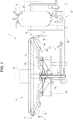
Figure 1 is a schematic side view, partially sectioned and with parts removed for clarity, of a filling machine provided with a plurality of filling devices obtained according to the teachings of the present invention; -
Figure 2 is a perspective view, with parts removed for clarity, of a filling device of the filling machine ofFigure 1 , taken individually; -
Figure 3 is a larger-scale axial cross section, with parts removed for clarity, of the filling device ofFigure 2 ; -
Figures 4a ,4b , and4c illustrate the filling device according to the invention, in an axial cross-sectional view similar to that ofFigure 3 , during different and successive operating conditions, in which it co-operates with parts of the filling machine ofFigure 1 represented schematically; and -
Figure 5 illustrates a larger-scale perspective view of a detail of the filling machine ofFigure 1 . - With reference to
Figure 1 , number 1 indicates as a whole a filling machine configured for filling a plurality ofreceptacles 2 with a pourable product at a pressure value higher than atmospheric pressure. In particular, thereceptacles 2 are made of metallic material, and the pourable product is a liquid with the addition of gas under pressure, for example a carbonated beverage. - The machine 1 comprises a rotary conveyor, preferably a
carousel 3, configured for turning about a vertical axis A, and atank 5 containing the pourable product under pressure and positioned peripherally with respect to thecarousel 3 itself. - Preferably, the
carousel 3 receives a succession ofempty receptacles 2 from an input starwheel (not illustrated), and directs thefull receptacles 2 towards an output starwheel (not illustrated either). - The
carousel 3 carries in cantilever manner, at aperipheral portion 3a thereof, a plurality offilling devices 4 configured for fillingrespective receptacles 2 up to a pre-set level during the rotation of thecarousel 3 about the axis A. - The
filling devices 4 are hence conveyed by thecarousel 3 along a circular transfer path in respective positions at equal radially equidistant about the axis A. - In particular, each
filling device 4 is fluidically connected to thetank 5 by means of acircuit 6 configured for conveying the pourable product from thetank 5 to thefilling device 4. - According to a preferred embodiment of the invention, each
receptacle 2 is defined by a substantially cylindrical can, which has a longitudinal axis B and is fed, in a vertical position, by thecarousel 3. In particular, eachreceptacle 2 is fed by thecarousel 3 with its own axis B parallel to the axis A of thecarousel 3 itself and in a lower position with respect to thecorresponding filling device 4. - In greater detail (
Figures 3 and4a-4c ), eachreceptacle 2 has a body 7 coaxial with axis B and delimited at the top by anannular edge 9, which delimits a circular end opening 9a of thereceptacle 2 itself. - With reference to
Figures 3 and4a-4c , each fillingdevice 4 further comprises a fillingvalve 8, which can be selectively activated for controlling outflow of the pourable product into arespective receptacle 2 to be filled. In this configuration, theedge 9 of thereceptacle 2 is set in contact with the fillingvalve 8 itself so as to receive from the latter the pourable product in a fluid-tight condition. - Hence, each filling
device 4 is configured for carrying out a so-called contact filling operation, where therespective receptacle 2 is supported in fluid-tight contact against the corresponding fillingvalve 8. - The
above filling valve 8 basically comprises: - a vertical
tubular body 11, which is fixed to theperipheral portion 3a of thecarousel 3, has a longitudinal axis C, parallel to the axis A of thecarousel 3 itself, and defines acentral flow channel 12 configured to feed the pourable product to therespective receptacle 2; - a
shutter 13, which slidably engages thetubular body 11 and is mobile within thechannel 12 so as to enable or prevent the outflow of the pourable product into therespective receptacle 2 to be filled; and - an
actuator 30 designed to move the shutter within thechannel 12. - In particular, the
tubular body 11 has atop end portion 14, anintermediate portion 17 provided with a transverse inlet opening 15 configured for receiving the pourable product from thetank 5 through thecircuit 6, and abottom end portion 16 terminating with an axial outlet opening 18 configured for supplying the pourable product into therespective receptacle 2. - With reference to the preferred embodiment illustrated in the attached figures, the
channel 12 comprises, at thebottom end portion 16 of thetubular body 11, aportion 22 with variable section, which defines the terminal part of thechannel 12 itself. - In particular, the
portion 22 comprises twofrustoconical stretches stretch 23 is positioned upstream of thestretch 24 with respect to the direction of feed of the pourable product into thechannel 12; i.e. it is set in a higher position with respect to thestretch 24, and has a cross section that tapers towards the latter; thestretch 24 has, instead, a diameter increasing from thestretch 23 to theoutlet opening 18. The two stretches 23, 24 define anarrow section 25 between them. - As may be seen in
Figure 3 and inFigures 4a-4c , theshutter 13 is mounted coaxially within thechannel 12 of thetubular body 11. - In particular, the
shutter 13 comprises an externally cylindricaltop portion 26, abottom portion 27, having a diameter larger than the diameter of thetop portion 26 and extending axially from the latter in the direction of theoutlet opening 18, and a shapedterminal portion 27a, configured for co-operating with the portion of thetubular body 11 that defines theportion 22 with variable section of thechannel 12. - In particular, the
terminal portion 27a is provided with a sealingring 28, preferably an O-ring made of elastomeric material, configured for co-operating selectively in a fluid-tight manner with thenarrow section 25 of thechannel 12 so as to prevent the outflow of the pourable product into theoutlet opening 18 and, hence, into thereceptacle 2 to be filled. - For this purpose, the
shutter 13 is mobile within thechannel 12 of thetubular body 11 between: - a lower closed position (
Figures 3 ,4a , and4c ), in which theshutter 13 closes thenarrow section 25 of thechannel 12, in a fluid-tight manner, via the sealingring 28, interrupting the outflow of the pourable product into therespective receptacle 2; and - an upper open position (
Figure 4b ), in which theshutter 13 delimits with the narrow section of thechannel 12 an annular passage communicating fluidically with the outlet opening 18 so as to enable the outflow of the pourable product into therespective receptacle 2 to be filled. - The movement of the
shutter 13 from the closed position to the open position is obtained via theactuator 30, the latter preferably being a fluid actuator, for example a pneumatic piston coupled to theshutter 13 in a known way not described in detail. - Alternatively, the movement of the
shutter 13 could be obtained by means of a mechanical or electromagnetic actuator. - As illustrated in
Figure 5 , each fillingdevice 4 further comprises a supporting element 55 (only one of which is illustrated inFigure 5 ) designed to receive and keep arespective receptacle 2 in a vertical position. In particular, the latter is kept in a lower position with respect to thefilling device 4 and coaxial with the axis C at least during activation of the fillingvalve 8. - With reference to
Figures 1 ,3 , and4a-4c , the machine 1 further comprises: - a pressurising/discharging
circuit 31 configured both for pressurising therespective receptacle 2 at a pre-set pressure value higher than the value of atmospheric pressure before starting effective filling, and for expelling the gas present in thereceptacle 2 during the filling operation; and - a
decompression circuit 32 configured for carrying out a decompression step of therespective receptacle 2 by causing exit of gas, once filling is completed. - In particular, the pressurising/discharging
circuit 31 comprises, for each fillingdevice 4, aduct 33 that fluidically connects the internal environment of therespective receptacle 2 to anannular chamber 34 of the pressurising/dischargingcircuit 31 itself, which is provided in thecarousel 3 and contains a gas under pressure, for example carbon dioxide. Theduct 33 further comprises a flow-control valve 35, preferably of a pneumatic type, configured for enabling or preventing flow of the gas under pressure from or towards thechamber 32. - The
decompression circuit 32 comprises, for each fillingdevice 4, aduct 36 that fluidically connects the internal environment of therespective receptacle 2 to anannular chamber 37 provided in thecarousel 3. Thechamber 37 is kept at a pressure lower than the pressure inside thereceptacle 2 at the end of filling and can in turn be connected to the external environment at atmospheric pressure in a known way not described in detail. Theduct 36 further comprises a flow-control valve 38, preferably of a pneumatic type, configured for selectively opening or closing the fluidic communication between thechamber 37 and theduct 36. - In order to ensure proper positioning of the
receptacles 2 during the filling operation, each fillingdevice 4 comprises a sealingsleeve 19 axially slidable, in use, through a purposely providedannular seat 20 provided in theend portion 16 of thetubular body 11. - In particular, the
sleeve 19 is axially slidable through theseat 20 between a upper release position, where it is at a certain distance from theedge 9 of therespective receptacle 2 and is located at least partially within theseat 20, and a lower sealing position, where it is almost totally extracted from theseat 20 itself and co-operates, in use, in a fluid-tight manner with theedge 9 of therespective receptacle 2. - For this purpose, the
sleeve 19 comprises, at an axial end thereof facing, in use, thereceptacle 2, anannular gasket 21, which has a sealingsurface 21a that defines, in use, an axial abutment for theedge 9 of therespective receptacle 2. In particular, the sealingsurface 21a co-operates, in use, in a fluid-tight manner with theedge 9 during the filling process. In this way, the internal volume of the body 7 of theaforesaid receptacle 2 is maintained in fluid-tight conditions throughout this process. - According to an important aspect of the present invention, each filling
device 4 further comprises elastic means, in particular agas spring 56, which have an elastic stiffness that can be selectively modified according to the diameter of theopening 9a delimited by theedge 9 of therespective receptacle 2. - In particular, as may be seen in
Figures 3 and4a-4c , thegas spring 56 comprises a mobile member, preferably aplunger 40 that is axially slidable, in use, within anaxial compartment 39 provided at thetop end portion 14 of thetubular body 11. - In greater detail, the
plunger 40 delimits, on one side of thecompartment 39, a sealedtop chamber 41, configured to be filled with a gas, for example air, at a pre-set pressure value P0 that can be modified according to the diameter of theopening 9a of therespective receptacle 2. - Hence, said pressure value P0 defines the elastic stiffness of the
gas spring 56. - The
top chamber 41 is configured for being selectively filled at different pressure values proportional to the diameter of theopening 9a ofreceptacles 2 of different format and/or size. - The
plunger 40 moreover delimits, on the side of thecompartment 39 axially opposite to that of thetop chamber 41, a sealedbottom chamber 42 configured for being selectively filled/emptied with/from the aforesaid gas at the same pressure value P0. - In practice, the
plunger 40 divides, in a fluid-tight manner, thecompartment 39 into thetop chamber 41 and thebottom chamber 42. - Preferably, the gas under pressure accesses the
chambers - The
plunger 40 comprises atop surface 43, facing thetop chamber 41, and abottom surface 44, facing thebottom chamber 42. The gas under pressure present, in use, in thesechambers aforesaid surfaces plunger 40 and cause axial sliding thereof within thecompartment 39. - In practice, the gas under pressure generates a first force on the
top surface 43, which in use, pushes theplunger 40 along the axis C in the direction of therespective receptacle 2 to be filled, and a second force, opposed to the first, on thebottom surface 44, which in use, pushes theplunger 40 along the axis C in the opposite direction with respect to therespective receptacle 2. - The
plunger 40 is likewise configured for controlling the axial sliding of thesleeve 19 that carries theannular gasket 21 between the aforesaid sealing and release positions. For this purpose, thesleeve 19 is connected to theplunger 40 by means of two rigidaxial bars 45, which are located on the outside of thetubular body 11 on diametrally opposite sides, as partially illustrated inFigure 2 . In greater detail, eachbar 45 is connected, at an axial end thereof, to astem 46 axially projecting from theplunger 40 and, at the opposite axial end, to anannular plate 47 fixed to thesleeve 19. - In this way, corresponding to an axial displacement of the
plunger 40 is an axial displacement of thesleeve 19 and, hence, of theannular gasket 21 between the sealing and release positions. - More specifically, when the
bottom chamber 42 is emptied from the gas under pressure, the force acting on thebottom surface 44 decreases progressively, and theplunger 40 can slide within thecompartment 39 downwards, as a result of the force acting on thetop surface 43, generated by the gas under pressure constantly present in thetop chamber 41. Consequently, thesleeve 19, connected to theplunger 40 via thebars 45, slides within theseat 20 towards the sealing position. The sealingsurface 21a of theannular gasket 21 can in this way co-operate with theedge 9 of therespective receptacle 2. - Instead, when the
bottom chamber 42 is filled with the gas under pressure, the force acting on thebottom surface 44 increases progressively, opposing the force acting on thetop surface 43, and theplunger 40 can slide within thecompartment 39 upwards. Consequently, thesleeve 19 slides in theseat 20 towards the release position, and the sealingsurface 21a of theannular gasket 21 moves away from thetop edge 9 of therespective receptacle 2. - As illustrated in
Figures 4a-4c , when thesleeve 19 is set in the sealing position, theedge 9 of therespective receptacle 2 delimits, on the sealingsurface 21a of theannular gasket 21 towards the axis B, an annular workingsurface 48. This workingsurface 48 has a radial extension proportional to the diameter of theopening 9a of therespective receptacle 2 and is lapped, in use, by the aforesaid gas under pressure used for pressurising the internal environment of thereceptacle 2 itself during the pressurising step. - The gas hence exerts on the working
surface 48 of theannular gasket 21 a force in the direction of thecompartment 39, which is thus transmitted to thesleeve 19; this force is all the higher, the greater the extension of the workingsurface 48 itself and, hence, the greater the diameter of theopening 9a of thereceptacle 2. - Consequently, as the diameter of the
openings 9a of thereceptacles 2 processed by the machine 1 varies, thesleeve 19 will have to oppose a different force (stronger as the diameter of theopenings 9a increases) to reach the sealing position and co-operate in a fluid-tight manner with therespective edge 9 of theaforesaid receptacles 2. - The foregoing can be obtained by filling the
top chamber 41, prior to the filling operation, with a gas at a pressure value P1 higher than the pressure value P0, proportional to the diameter of theopening 9a of therespective receptacle 2. There will thus be a force of greater intensity generated by the new gas under pressure on thetop surface 43 of theplunger 40 and transmitted, by means of thebars 45, to thesleeve 19, that will be able to oppose the aforesaid force generated by the pressurising gas and applied to the workingsurface 48 delimited on theannular gasket 21. - As can be seen in the attached figures, each filling
device 4 further comprises a cam-follower roller 50, which is mounted on thestem 46 of theplunger 40, preferably by means of abar 49 radially projecting from the latter, and co-operates, in use, with a fixedcam 51, mounted on thecarousel 3 and extending circumferentially on theperipheral portion 3a through a certain angle about the axis A. - In particular, the
roller 50 is configured for co-operating with thecam 51 in order to ensure a gradual downward displacement of theplunger 40 within thecompartment 39 and, consequently, of thesleeve 19 from the release position towards the sealing position. - Considering the direction of rotation of the
carousel 3, thecam 51 has (Figures 5 and 6): - a
release portion 52, which has an increasing height with respect to the axis A and hence defines an ascending ramp for theroller 50; - a
central portion 53 with constant height with respect to the axis A; and - an
attack portion 54, which has a decreasing height with respect to the axis A itself and hence defines a descending ramp for theroller 50. - More specifically, in normal operating conditions, each
roller 50 co-operates only with theattack portion 54 in order to ensure a gradual descent of therespective plunger 40 when this slides axially downwards within therespective compartment 39 following upon exit of the gas under pressure from thebottom chamber 42. In this way, thesleeve 19 can slide gradually from the release position towards the sealing position, and theannular gasket 21 can come into contact with theedge 9 of therespective receptacle 2 delicately, preventing sharp displacements that could cause crushing of the body 7 of thereceptacle 2 itself. - In normal operating conditions, each
roller 50 does not co-operate in contact with therelease portion 52 and thecentral portion 53 and, hence, the upward end-of-travel position of theroller 50 and the release position of thesleeve 19 are designed so that there will be a certain non-zero distance between theroller 50 itself and therelease portion 52 and thecentral portion 53 of thecam 51. - Consequently, the
aforesaid release portion 52 andcentral portion 53 of thecam 51 basically perform a safety function: they are configured to move theroller 50, and hence theplunger 40 and thesleeve 19, upwards in the case in which these remain blocked downwards in the event of anomalous operating conditions. In the latter case, theroller 50, and hence theplunger 40 and thesleeve 19, do not reach the respective upward end-of-travel position (for example, the release position for the sleeve 19). - In addition, the
release portion 52 presents a slight slope and a length greater than the slope and the length of theattack portion 54, in order to guide theroller 50 to perform the displacement upwards, preventing any sharp movements that might cause impact. The more accentuated slope and smaller length of theattack portion 54 as compared to those of therelease portion 52 derive from the need for rapidly providing a support for thereceptacle 2 to be filled, once it has entered thecarousel 3 via the input starwheel. - The operation of the filling machine 1 according to the present invention will be described in what follows with reference to a
single filling device 4 carried by thecarousel 3 and to asingle receptacle 2 to be filled. - In particular,
Figures 4a to 4c illustrate the operation of the filling machine 1 during three successive operating conditions. - In detail, as illustrated in
Figure 4a , thereceptacle 2 to be filled is fed by thecarousel 3 in a lower position with respect to thefilling device 4 and is positioned so as to be set with theedge 9 of the body 7 bearing upon theannular gasket 21 of thetubular body 11. For this purpose, theplunger 40 controls, by causing exit of the gas under pressure from thebottom chamber 42, displacement of thesleeve 19 from the release position to the sealing position. This displacement occurs gradually thanks to the interaction of theroller 50 with theattack portion 54 of thecam 51. Once fluid-tight contact between thereceptacle 2 and thetubular body 11 has been ensured, thevalve 35 is opened to start the pressurising step: the gas under pressure contained in thechamber 34 flows along the pressurising/dischargingcircuit 31, into thereceptacle 2, until the pressure inside the latter reaches the value of the pressure of thetank 5 that contains the pourable product to be poured into thereceptacle 2 itself. - Once this step is completed, as illustrated in
Figure 4b , theshutter 13 is displaced, via theactuator 30, from the closed position to the open position. The pourable product can hence flow into thechannel 12, through theoutlet opening 18 and, then, into thereceptacle 2. At the same time, the gas contained in thereceptacle 2 is expelled via the pressurising/dischargingcircuit 31. - Once filling is completed, as illustrated in
Figure 4c , theshutter 13 is displaced into the closed position by means of theactuator 30, and thevalve 35 is closed. - At this point, the
valve 38 is opened to start the decompression step: thereceptacle 2 is depressurized by causing the gas contained in the top part of the body 7 to flow out along thedecompression circuit 32, towards thechamber 37. - Once the decompression step is completed, the
plunger 40 controls, by filling thebottom chamber 42 with the gas under pressure, displacement of thesleeve 19 from the sealing position to the release position (Figure 3 ). Conveniently, filling of thebottom chamber 42 occurs before theroller 50 reaches therelease portion 52 of thecam 51, so as to prevent, in normal operating conditions, any undesirable contact of theroller 50 with theaforesaid portion 52. At this point, as long as theroller 50 passes over thecentral portion 53, thefull receptacle 2 is conveyed towards the output starwheel, and a newempty receptacle 2 is positioned underneath the fillingvalve 8. - In the case where anomalous operating conditions were to arise, on account of which the
plunger 40 and, hence, thesleeve 19 were to remain blocked downwards, theroller 50 would come into contact with therelease portion 52, which would determine an upward movement of theroller 50 itself. Consequently, thesleeve 19 would be displaced upwards as far as an intermediate position between the release position and the sealing position. At this point, the roller would co-operate with thecentral portion 53, and thereceptacle 2, forcibly separated from theannular gasket 21, would be conveyed towards the output starwheel, and the filling machine 1 would be stopped in order to check for possible problems. - It is clear that what has been described above applies in the same way to each filling
device 4 and to eachreceptacle 2 to be filled. - The advantages of filling
device 4 according to the present invention will be clear from the foregoing description. - In particular, the filling
device 4 makes it possible to handlereceptacles 2 of different formats and/or dimensions without any need to replace the elastic means acting on thesleeve 19. In practice, in the case of a change of format of thereceptacles 2, it is sufficient to fill thetop chamber 41 of thecompartment 39 with a gas at a pressure value correlated to the diameter of theopening 9a of thenew receptacle 2. - It is clear that modifications and variations may be made to the
filling device 4 described and illustrated herein, without thereby departing from the scope of protection defined by the claims. - In particular, the
opening 9a of thereceptacle 2 could have a non-circular shape, for example elliptical, and, hence, the elastic stiffness of thegas spring 56 could be selectively modified according to the dimensions of theopening 9a itself.
Claims (10)
- A device (4) of filling receptacles (2) with a pourable product under pressure; said filling device (4) having a longitudinal axis (C) and comprising: a filling valve (8), which can be selectively activated for supplying said pourable product into a respective receptacle (2) through an opening (9a) of the latter; a sealing member (21), which has a sealing surface (21a) configured to co-operate, in use, in a fluid-tight manner with an edge (9) of said opening (9a), and a supporting member (55) configured to keep said opening (9a) coaxial to said sealing member (21) at least during activation of said filling valve (8);
wherein at least one of said sealing member (21) and said supporting member (55) is mobile, in use, between:- a sealing position, where it determines fluid-tight contact between said edge (9) of said opening (9a) and said sealing surface (21a); and- a release position, where it maintains a certain distance between said edge (9) of said opening (9a) and said sealing surface (21a);said filling device (4) further comprising elastic means generating on said one of said sealing member (21) and said supporting member (55) a thrust towards said sealing position;
characterized in that said elastic means have an elastic stiffness that is selectively modifiable according to the size/s of said opening (9a) of said receptacle (2). - The device according to claim 1, wherein said elastic means include a gas spring (56) comprising a sealed chamber (41) that can be filled, in use, with a gas at a pre-set pressure value (P0) that can be modified according to the size/s of said opening (9a) of said receptacle (2) and is correlated to said elastic stiffness.
- The device according to claim 2, wherein said gas spring (56) further comprises a compartment (39) and a mobile member (40), which can be displaced, in use, in a fluid-tight manner within said compartment (39) and is configured to move said one of said sealing member (21) and said supporting member (55) between said sealing position and said release position; said mobile member (40) dividing said compartment (39) into said chamber (41) and into a further sealed chamber (42) that can be selectively filled/emptied, in use, with/from a gas at a pre-set pressure value, so as to determine said displacement of said mobile member (40) within said compartment (39).
- The device according to claim 3, wherein said mobile member (40) is connected to said one of said sealing member (21) and said supporting member (55) by means of at least one rigid element (45), in such a way that to a said displacement of said mobile member (40) within said compartment (39) there corresponds a displacement of said one of said sealing member (21) and said supporting member (55) .
- The device according to Claim 4, wherein said mobile member (40) comprises a first surface (43), facing said chamber (41), and a second surface (44), facing said further chamber (42); said gas contained in said chamber (41) at said pressure value (P0) interacting, in use, with said first surface (43) so as to push said one of said sealing member (21) and said supporting member (55) towards said sealing position; said gas contained in said further chamber (42) at said pressure value (P0) interacting, in use, with said second surface (44) so as to push said one of said sealing member (21) and said supporting member (55) towards said release position.
- The device according to claim 4 or 5, wherein said mobile member (40) moves, in use, said one of said sealing member (21) and said supporting member (55) towards said sealing position, when said further chamber (42) is emptied from said gas under pressure;
said mobile member (40) moving, in use, said one of said sealing member (21) and said supporting member (55) towards said release position when said further chamber (42) is filled with said gas under pressure. - The device according to any one of the foregoing claims, wherein said filling valve (8) comprises a hollow body (11) coaxial with said axis (C), defining a channel (12) of flow for said pourable product and terminating at one end (16) thereof with an outlet opening (18) configured to feed said pourable product to said receptacle (2); and wherein said sealing member (21) is mobile with respect to said hollow body (11) between said sealing position and said release position.
- The device according to claim 7, wherein said sealing member (21) is carried by a sleeve (19), which is axially slidable with respect to said hollow body (11).
- The device according to any one of the foregoing claims, wherein said displacement of said one of said sealing member (21) and said supporting member (55) from said release position to said sealing position is controlled via interaction of a cam-follower element (50), which is fixed with respect to said one of said sealing member (21) and said supporting member (55), and a fixed cam (51).
- A filling machine (1) comprising at least one filling device (4) built according to any one of the foregoing claims.
Applications Claiming Priority (1)
| Application Number | Priority Date | Filing Date | Title |
|---|---|---|---|
| IT201700138400 | 2017-11-30 |
Publications (1)
| Publication Number | Publication Date |
|---|---|
| EP3498657A1 true EP3498657A1 (en) | 2019-06-19 |
Family
ID=61527468
Family Applications (1)
| Application Number | Title | Priority Date | Filing Date |
|---|---|---|---|
| EP18207298.3A Withdrawn EP3498657A1 (en) | 2017-11-30 | 2018-11-20 | A device of filling receptacles with a pourable product under pressure |
Country Status (1)
| Country | Link |
|---|---|
| EP (1) | EP3498657A1 (en) |
Citations (4)
| Publication number | Priority date | Publication date | Assignee | Title |
|---|---|---|---|---|
| US4674547A (en) * | 1984-10-02 | 1987-06-23 | Andriano Simonazzi | Container filling apparatus with adjustable pressure sealing means |
| WO1994010079A1 (en) * | 1992-10-30 | 1994-05-11 | Simonazzi S.P.A. | A process for filling containers, in particular cans, with liquids, and a filler valve group for carrying out the process |
| JP2002370797A (en) * | 2001-06-12 | 2002-12-24 | Shibuya Kogyo Co Ltd | Filling valve |
| DE102008011109A1 (en) * | 2008-02-26 | 2009-09-03 | Khs Ag | Filling element for filling containers with a liquid filling material, as well as filling machine |
-
2018
- 2018-11-20 EP EP18207298.3A patent/EP3498657A1/en not_active Withdrawn
Patent Citations (4)
| Publication number | Priority date | Publication date | Assignee | Title |
|---|---|---|---|---|
| US4674547A (en) * | 1984-10-02 | 1987-06-23 | Andriano Simonazzi | Container filling apparatus with adjustable pressure sealing means |
| WO1994010079A1 (en) * | 1992-10-30 | 1994-05-11 | Simonazzi S.P.A. | A process for filling containers, in particular cans, with liquids, and a filler valve group for carrying out the process |
| JP2002370797A (en) * | 2001-06-12 | 2002-12-24 | Shibuya Kogyo Co Ltd | Filling valve |
| DE102008011109A1 (en) * | 2008-02-26 | 2009-09-03 | Khs Ag | Filling element for filling containers with a liquid filling material, as well as filling machine |
Similar Documents
| Publication | Publication Date | Title |
|---|---|---|
| EP1995208B2 (en) | Rotary filling machine for filling containers with liquids | |
| EP2871150B1 (en) | Filling unit and method for filling an article with a pourable product | |
| EP3453673B1 (en) | Machine for filling containers with liquids, provided with a filling level correction system | |
| US10040678B2 (en) | Filling devices for filling machines for level filling of bottles and filling machines containing such devices | |
| EP2751017B1 (en) | Container treating machine | |
| US9604834B2 (en) | Filler element comprising a Trinox tube | |
| EP3177539B1 (en) | Unit and method for filling containers of single-use capsules for extraction or infusion beverages | |
| SE466194B (en) | FILLING VALVES FOR CANNES AND SIMILAR CONTAINERS | |
| US20170057801A1 (en) | Method and filling system for filling containers | |
| US9004904B2 (en) | Apparatus for moulding plastic preforms | |
| EP3498658B1 (en) | A filling machine for filling receptacles with a pourable product under pressure | |
| US6520221B2 (en) | Filling nozzle with interception of supply liquids for filling machines | |
| EP3421411B1 (en) | Filling unit for filling an article with a pourable product | |
| EP1457457A2 (en) | Filling head | |
| EP3206960B1 (en) | Device and method for feeding and dosing filter bags with infusion or extraction products | |
| EP2354081B1 (en) | A device for dispensing a product in a filling machine | |
| EP3473589A1 (en) | Filling machine and method for filling receptacles with a pourable product under pressure | |
| EP2534089B1 (en) | Filling system for filling containers in a pressurized manner | |
| EP2949617B1 (en) | Unit and method for contact or contactless filling an article with pourable food product | |
| EP4464651A1 (en) | Valve assembly for a filling machine and filling machine provided with such a valve | |
| EP2634133A1 (en) | Filling device | |
| EP2548838B1 (en) | Device for filling containers and relative method of washing | |
| EP3980366B1 (en) | Filling valve for filling receptacles with a pourable product | |
| JP2023530599A (en) | self-draining separator |
Legal Events
| Date | Code | Title | Description |
|---|---|---|---|
| PUAI | Public reference made under article 153(3) epc to a published international application that has entered the european phase |
Free format text: ORIGINAL CODE: 0009012 |
|
| STAA | Information on the status of an ep patent application or granted ep patent |
Free format text: STATUS: THE APPLICATION HAS BEEN PUBLISHED |
|
| AK | Designated contracting states |
Kind code of ref document: A1 Designated state(s): AL AT BE BG CH CY CZ DE DK EE ES FI FR GB GR HR HU IE IS IT LI LT LU LV MC MK MT NL NO PL PT RO RS SE SI SK SM TR |
|
| AX | Request for extension of the european patent |
Extension state: BA ME |
|
| STAA | Information on the status of an ep patent application or granted ep patent |
Free format text: STATUS: REQUEST FOR EXAMINATION WAS MADE |
|
| 17P | Request for examination filed |
Effective date: 20191206 |
|
| RBV | Designated contracting states (corrected) |
Designated state(s): AL AT BE BG CH CY CZ DE DK EE ES FI FR GB GR HR HU IE IS IT LI LT LU LV MC MK MT NL NO PL PT RO RS SE SI SK SM TR |
|
| STAA | Information on the status of an ep patent application or granted ep patent |
Free format text: STATUS: THE APPLICATION IS DEEMED TO BE WITHDRAWN |
|
| 18D | Application deemed to be withdrawn |
Effective date: 20210601 |