EP3498517A1 - Surface wrapped user interface touch control - Google Patents
Surface wrapped user interface touch control Download PDFInfo
- Publication number
- EP3498517A1 EP3498517A1 EP18211819.0A EP18211819A EP3498517A1 EP 3498517 A1 EP3498517 A1 EP 3498517A1 EP 18211819 A EP18211819 A EP 18211819A EP 3498517 A1 EP3498517 A1 EP 3498517A1
- Authority
- EP
- European Patent Office
- Prior art keywords
- touch
- control
- touch control
- zone
- illumination
- Prior art date
- Legal status (The legal status is an assumption and is not a legal conclusion. Google has not performed a legal analysis and makes no representation as to the accuracy of the status listed.)
- Granted
Links
Images

Classifications
-
- G—PHYSICS
- G06—COMPUTING OR CALCULATING; COUNTING
- G06F—ELECTRIC DIGITAL DATA PROCESSING
- G06F3/00—Input arrangements for transferring data to be processed into a form capable of being handled by the computer; Output arrangements for transferring data from processing unit to output unit, e.g. interface arrangements
- G06F3/01—Input arrangements or combined input and output arrangements for interaction between user and computer
- G06F3/03—Arrangements for converting the position or the displacement of a member into a coded form
- G06F3/041—Digitisers, e.g. for touch screens or touch pads, characterised by the transducing means
- G06F3/0416—Control or interface arrangements specially adapted for digitisers
- G06F3/04164—Connections between sensors and controllers, e.g. routing lines between electrodes and connection pads
-
- G—PHYSICS
- G06—COMPUTING OR CALCULATING; COUNTING
- G06F—ELECTRIC DIGITAL DATA PROCESSING
- G06F3/00—Input arrangements for transferring data to be processed into a form capable of being handled by the computer; Output arrangements for transferring data from processing unit to output unit, e.g. interface arrangements
- G06F3/01—Input arrangements or combined input and output arrangements for interaction between user and computer
- G06F3/048—Interaction techniques based on graphical user interfaces [GUI]
- G06F3/0487—Interaction techniques based on graphical user interfaces [GUI] using specific features provided by the input device, e.g. functions controlled by the rotation of a mouse with dual sensing arrangements, or of the nature of the input device, e.g. tap gestures based on pressure sensed by a digitiser
- G06F3/0488—Interaction techniques based on graphical user interfaces [GUI] using specific features provided by the input device, e.g. functions controlled by the rotation of a mouse with dual sensing arrangements, or of the nature of the input device, e.g. tap gestures based on pressure sensed by a digitiser using a touch-screen or digitiser, e.g. input of commands through traced gestures
- G06F3/04883—Interaction techniques based on graphical user interfaces [GUI] using specific features provided by the input device, e.g. functions controlled by the rotation of a mouse with dual sensing arrangements, or of the nature of the input device, e.g. tap gestures based on pressure sensed by a digitiser using a touch-screen or digitiser, e.g. input of commands through traced gestures for inputting data by handwriting, e.g. gesture or text
-
- B—PERFORMING OPERATIONS; TRANSPORTING
- B60—VEHICLES IN GENERAL
- B60K—ARRANGEMENT OR MOUNTING OF PROPULSION UNITS OR OF TRANSMISSIONS IN VEHICLES; ARRANGEMENT OR MOUNTING OF PLURAL DIVERSE PRIME-MOVERS IN VEHICLES; AUXILIARY DRIVES FOR VEHICLES; INSTRUMENTATION OR DASHBOARDS FOR VEHICLES; ARRANGEMENTS IN CONNECTION WITH COOLING, AIR INTAKE, GAS EXHAUST OR FUEL SUPPLY OF PROPULSION UNITS IN VEHICLES
- B60K35/00—Instruments specially adapted for vehicles; Arrangement of instruments in or on vehicles
- B60K35/10—Input arrangements, i.e. from user to vehicle, associated with vehicle functions or specially adapted therefor
-
- B—PERFORMING OPERATIONS; TRANSPORTING
- B60—VEHICLES IN GENERAL
- B60K—ARRANGEMENT OR MOUNTING OF PROPULSION UNITS OR OF TRANSMISSIONS IN VEHICLES; ARRANGEMENT OR MOUNTING OF PLURAL DIVERSE PRIME-MOVERS IN VEHICLES; AUXILIARY DRIVES FOR VEHICLES; INSTRUMENTATION OR DASHBOARDS FOR VEHICLES; ARRANGEMENTS IN CONNECTION WITH COOLING, AIR INTAKE, GAS EXHAUST OR FUEL SUPPLY OF PROPULSION UNITS IN VEHICLES
- B60K37/00—Dashboards
- B60K37/20—Dashboard panels
-
- G—PHYSICS
- G06—COMPUTING OR CALCULATING; COUNTING
- G06F—ELECTRIC DIGITAL DATA PROCESSING
- G06F3/00—Input arrangements for transferring data to be processed into a form capable of being handled by the computer; Output arrangements for transferring data from processing unit to output unit, e.g. interface arrangements
- G06F3/01—Input arrangements or combined input and output arrangements for interaction between user and computer
- G06F3/03—Arrangements for converting the position or the displacement of a member into a coded form
- G06F3/041—Digitisers, e.g. for touch screens or touch pads, characterised by the transducing means
- G06F3/0412—Digitisers structurally integrated in a display
-
- G—PHYSICS
- G06—COMPUTING OR CALCULATING; COUNTING
- G06F—ELECTRIC DIGITAL DATA PROCESSING
- G06F3/00—Input arrangements for transferring data to be processed into a form capable of being handled by the computer; Output arrangements for transferring data from processing unit to output unit, e.g. interface arrangements
- G06F3/01—Input arrangements or combined input and output arrangements for interaction between user and computer
- G06F3/03—Arrangements for converting the position or the displacement of a member into a coded form
- G06F3/041—Digitisers, e.g. for touch screens or touch pads, characterised by the transducing means
- G06F3/0416—Control or interface arrangements specially adapted for digitisers
-
- G—PHYSICS
- G06—COMPUTING OR CALCULATING; COUNTING
- G06F—ELECTRIC DIGITAL DATA PROCESSING
- G06F3/00—Input arrangements for transferring data to be processed into a form capable of being handled by the computer; Output arrangements for transferring data from processing unit to output unit, e.g. interface arrangements
- G06F3/01—Input arrangements or combined input and output arrangements for interaction between user and computer
- G06F3/048—Interaction techniques based on graphical user interfaces [GUI]
- G06F3/0484—Interaction techniques based on graphical user interfaces [GUI] for the control of specific functions or operations, e.g. selecting or manipulating an object, an image or a displayed text element, setting a parameter value or selecting a range
- G06F3/04847—Interaction techniques to control parameter settings, e.g. interaction with sliders or dials
-
- G—PHYSICS
- G06—COMPUTING OR CALCULATING; COUNTING
- G06F—ELECTRIC DIGITAL DATA PROCESSING
- G06F3/00—Input arrangements for transferring data to be processed into a form capable of being handled by the computer; Output arrangements for transferring data from processing unit to output unit, e.g. interface arrangements
- G06F3/01—Input arrangements or combined input and output arrangements for interaction between user and computer
- G06F3/048—Interaction techniques based on graphical user interfaces [GUI]
- G06F3/0487—Interaction techniques based on graphical user interfaces [GUI] using specific features provided by the input device, e.g. functions controlled by the rotation of a mouse with dual sensing arrangements, or of the nature of the input device, e.g. tap gestures based on pressure sensed by a digitiser
- G06F3/0488—Interaction techniques based on graphical user interfaces [GUI] using specific features provided by the input device, e.g. functions controlled by the rotation of a mouse with dual sensing arrangements, or of the nature of the input device, e.g. tap gestures based on pressure sensed by a digitiser using a touch-screen or digitiser, e.g. input of commands through traced gestures
-
- H—ELECTRICITY
- H03—ELECTRONIC CIRCUITRY
- H03K—PULSE TECHNIQUE
- H03K17/00—Electronic switching or gating, i.e. not by contact-making and –breaking
- H03K17/94—Electronic switching or gating, i.e. not by contact-making and –breaking characterised by the way in which the control signals are generated
- H03K17/96—Touch switches
- H03K17/962—Capacitive touch switches
-
- B—PERFORMING OPERATIONS; TRANSPORTING
- B60—VEHICLES IN GENERAL
- B60K—ARRANGEMENT OR MOUNTING OF PROPULSION UNITS OR OF TRANSMISSIONS IN VEHICLES; ARRANGEMENT OR MOUNTING OF PLURAL DIVERSE PRIME-MOVERS IN VEHICLES; AUXILIARY DRIVES FOR VEHICLES; INSTRUMENTATION OR DASHBOARDS FOR VEHICLES; ARRANGEMENTS IN CONNECTION WITH COOLING, AIR INTAKE, GAS EXHAUST OR FUEL SUPPLY OF PROPULSION UNITS IN VEHICLES
- B60K2360/00—Indexing scheme associated with groups B60K35/00 or B60K37/00 relating to details of instruments or dashboards
- B60K2360/20—Optical features of instruments
- B60K2360/33—Illumination features
- B60K2360/336—Light guides
-
- B—PERFORMING OPERATIONS; TRANSPORTING
- B60—VEHICLES IN GENERAL
- B60K—ARRANGEMENT OR MOUNTING OF PROPULSION UNITS OR OF TRANSMISSIONS IN VEHICLES; ARRANGEMENT OR MOUNTING OF PLURAL DIVERSE PRIME-MOVERS IN VEHICLES; AUXILIARY DRIVES FOR VEHICLES; INSTRUMENTATION OR DASHBOARDS FOR VEHICLES; ARRANGEMENTS IN CONNECTION WITH COOLING, AIR INTAKE, GAS EXHAUST OR FUEL SUPPLY OF PROPULSION UNITS IN VEHICLES
- B60K2360/00—Indexing scheme associated with groups B60K35/00 or B60K37/00 relating to details of instruments or dashboards
- B60K2360/20—Optical features of instruments
- B60K2360/33—Illumination features
- B60K2360/339—Translucent dashboard skins
-
- B—PERFORMING OPERATIONS; TRANSPORTING
- B60—VEHICLES IN GENERAL
- B60K—ARRANGEMENT OR MOUNTING OF PROPULSION UNITS OR OF TRANSMISSIONS IN VEHICLES; ARRANGEMENT OR MOUNTING OF PLURAL DIVERSE PRIME-MOVERS IN VEHICLES; AUXILIARY DRIVES FOR VEHICLES; INSTRUMENTATION OR DASHBOARDS FOR VEHICLES; ARRANGEMENTS IN CONNECTION WITH COOLING, AIR INTAKE, GAS EXHAUST OR FUEL SUPPLY OF PROPULSION UNITS IN VEHICLES
- B60K2360/00—Indexing scheme associated with groups B60K35/00 or B60K37/00 relating to details of instruments or dashboards
- B60K2360/20—Optical features of instruments
- B60K2360/33—Illumination features
- B60K2360/34—Backlit symbols
-
- B—PERFORMING OPERATIONS; TRANSPORTING
- B60—VEHICLES IN GENERAL
- B60K—ARRANGEMENT OR MOUNTING OF PROPULSION UNITS OR OF TRANSMISSIONS IN VEHICLES; ARRANGEMENT OR MOUNTING OF PLURAL DIVERSE PRIME-MOVERS IN VEHICLES; AUXILIARY DRIVES FOR VEHICLES; INSTRUMENTATION OR DASHBOARDS FOR VEHICLES; ARRANGEMENTS IN CONNECTION WITH COOLING, AIR INTAKE, GAS EXHAUST OR FUEL SUPPLY OF PROPULSION UNITS IN VEHICLES
- B60K2360/00—Indexing scheme associated with groups B60K35/00 or B60K37/00 relating to details of instruments or dashboards
- B60K2360/20—Optical features of instruments
- B60K2360/33—Illumination features
- B60K2360/345—Illumination of controls
-
- B—PERFORMING OPERATIONS; TRANSPORTING
- B60—VEHICLES IN GENERAL
- B60K—ARRANGEMENT OR MOUNTING OF PROPULSION UNITS OR OF TRANSMISSIONS IN VEHICLES; ARRANGEMENT OR MOUNTING OF PLURAL DIVERSE PRIME-MOVERS IN VEHICLES; AUXILIARY DRIVES FOR VEHICLES; INSTRUMENTATION OR DASHBOARDS FOR VEHICLES; ARRANGEMENTS IN CONNECTION WITH COOLING, AIR INTAKE, GAS EXHAUST OR FUEL SUPPLY OF PROPULSION UNITS IN VEHICLES
- B60K2360/00—Indexing scheme associated with groups B60K35/00 or B60K37/00 relating to details of instruments or dashboards
- B60K2360/60—Structural details of dashboards or instruments
- B60K2360/68—Features of instruments
- B60K2360/688—Frames or decorative parts
Definitions
- the present disclosure relates to user interface control elements, and more particularly to a surface wrapped user interface touch control and methods of using same.
- Modern devices use a variety of control means to detect operational commands.
- conventional control interface elements such as simple push buttons and control knobs.
- the structure of conventional units impose structural requirements on a device.
- conventional push button switches may require an elevated or silo structure to allow for the button to be pressed.
- the structure of the conventional buttons do not allow for the buttons or input elements to be covered or wrapped by other materials.
- Typical push button elements are accompanied by a label or symbol identifying operation of the button.
- control interfaces Product designers are often faced with the task of designing control interfaces with a particular appearance. Often, new designs require advances in technology and component design to accommodate desired interface details. In the automotive industry, for example, many manufacturers develop new control interface layouts with new models and model refreshes. Due to one or more considerations, such as spacing, layout and weight, existing control interfaces do not meet the requirements of new designs. In many cases, changing size and shape of conventional buttons does not allow for the desired interface. In addition, functions of control interfaces change with advances in vehicle technology and function. There exists a desire for control interface elements that allows for use in a vehicle control interfaces and for device interfaces in general.
- a touch control device including a housing assembly including an outer surface, and a touch sensor mounted to an inner surface of the housing assembly.
- the touch sensor includes at least one touch zone and the touch sensor is configured to detect contact to the outer surface of the housing assembly associated with the at least one touch zone.
- the touch control device also includes at least one illumination element configured to illuminate a portion of the outer surface of the housing assembly associated with the at least one touch zone.
- the touch control device also includes a controller coupled to the touch sensor and the at least one illumination element. The controller is configured to illuminate the at least one illumination element in response to contact with the at least one touch zone, and output a control signal in response to contact with the at least one touch zone.
- the outer surface is a flat surface.
- the outer surface is a curved surface.
- the housing assembly mounts to a main panel and the touch control device and main panel are wrapped in a material.
- the touch sensor includes a plurality of touch zones.
- the illumination element includes at least one light source and at least one illumination area of the surface.
- the controller is mounted to the housing assembly and is configured to output touch commands detected by the touch sensor.
- the touch sensor includes at least one illumination element for each of the plurality of touch zones.
- One embodiment is directed to a method for operation of a touch control including detecting, by a touch control, an input to at least one touch zone of the touch control, wherein the input includes contact to a wrapped surface of the touch control.
- the method also includes controlling, by a controller of the touch control, illumination of at least one illumination element of the touch control in response to the input, and outputting, by a controller of the touch control, a control signal in response to contact with the at least one touch zone.
- the method includes illuminating at least one touch zone to signal the location of one or more touch zones of the touch control.
- the method includes updating at least one illumination parameters.
- touch zones may be illuminated with a light level increased in response to a detected input.
- One embodiment is directed to a surface wrapped touch control device including a housing assembly supporting an outer surface for a touch control and a touch sensor mounted to an inner surface of the housing assembly.
- the touch sensor includes at least one touch zone and the touch sensor is configured to detect contact to the outer surface of the housing assembly associated with the at least one touch zone.
- the surface wrapped touch control device also includes at least one illumination element configured to illuminate a portion of the outer surface of the housing assembly associated the at least one touch zone.
- the surface wrapped touch control device also includes a wrapping material applied to the outer surface and covering the touch sensor, wherein the wrapping material is configured to be illuminated by the at least one illumination element.
- the surface wrapped touch control device also includes a controller coupled to the touch sensor and the at least one illumination element, wherein the controller is configured to illuminate the at least one illumination element in response to contact with the at least one touch zone, and output a control signal in response to contact with the at least one touch zone.
- the outer surface is at least one of a flat and curved surface covered by the wrapping material.
- the housing assembly mounts to a main panel and the touch control device and main panel are wrapped in a material.
- the touch sensor includes a plurality of touch zones.
- the illumination element includes at least one light source and at least one illumination area of the surface.
- the controller is mounted to the housing assembly and is configured to output touch commands detected by the touch sensor.
- the touch sensor includes at least one illumination element for each of the plurality of touch zones.
- the touch sensor includes a light tube for each touch zone, wherein the light tube is configured to be illuminated and controlled to present one or more colors by the controller.
- a surface wrapped touch control including a material wrapping a surface and covering one or more sensing zones.
- the touch control is configured to illuminate one or more portions of the surface.
- the touch control is configured to provide one or more of a touch detection and slider operation. In that fashion, zones of the touch control may be contacted and operate as input elements.
- At least one of the touch sensing, illumination, and touch control structure are configured to allow for a material to wrap a surface of the touch control. Configurations and devices described herein may relate to flat and curved surfaces.
- vehicle configurations including one or more surfaces having at least one touch zone.
- the one or more assemblies of the touch control may be associated with a plurality of vehicle surfaces.
- the touch control assemblies may also be controlled to allow for control of vehicle units, such as climate control inputs and functions of a vehicle head unit (e.g., infotainment unit, navigation, unit, user interface display, etc.).
- Embodiments are also directed to operation and control of user interface touch controls.
- one or more illumination settings may be controlled to provide a feedback to a user.
- illumination settings and configurations of the touch control allow for a surface of the touch control to appear as a smooth surface while also allowing for contact with one or more touch zones. Illumination of the surface can provide notifications of detected contact.
- Embodiments and configurations discussed herein provide can allow for maintaining uninterrupted design while providing functional accessibility to common controls.
- touch control units may be applied to other devices and for additional applications.
- the terms “a” or “an” shall mean one or more than one.
- the term “plurality” shall mean two or more than two.
- the term “another” is defined as a second or more.
- the terms “including” and/or “having” are open ended (e.g., comprising).
- the term “or” as used herein is to be interpreted as inclusive or meaning any one or any combination. Therefore, “A, B or C” means “any of the following: A; B; C; A and B; A and C; B and C; A, B and C". An exception to this definition will occur only when a combination of elements, functions, steps or acts are in some way inherently mutually exclusive.
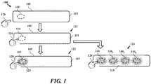
- FIG. 1 depicts operation of a user interface control according to one or more embodiments.
- a touch control device including a surface and one or more elements to detect contact with the surface.
- Embodiments are also directed to operation and control of user interface touch controls.
- one or more illumination settings may be controlled to provide a feedback to a user.
- illumination settings and configurations of the touch control allow for a surface of the touch control to appear as a smooth surface while also allowing for contact with one or more touch zones. Illumination of the surface can provide notifications of detected contact.
- Embodiments and configurations discussed herein can allow for maintaining uninterrupted design while providing functional accessibility to common controls.
- Touch control 100 may be a surface wrapped touch control including a material wrapping an outer surface 105 of the touch control and covering one or more sensing zones. Touch control 100 may be configured to illuminate one or more portions of surface 105. Touch control 100 may also provide one or more of a touch detection and slider operation. In that fashion, zones of touch control 100 may be contacted and operate as input elements. At least one of the touch sensing, illumination, and touch control structure are configured to allow for a material to wrap a surface of the touch control. Configurations and devices described herein may relate to flat and curved surfaces.
- touch control 100 includes surface 105 and at least one touch zone shown as 110 in FIG. 1 .
- touch control 100 includes a touch sensor (e.g., film touch sensor, capacitive touch sensor, flexible touch sensor, etc.) having at least one touch zone and one or more structural elements such as a sub-bezel or housing providing an outer surface.
- the touch sensor of touch control 100 may be mounted to an inner surface of the housing assembly. In that fashion, the touch sensor is configured to detect contact to the outer surface of the housing assembly associated with the at least one touch zone.
- touch control 100 may include a housing assembly or sub bezel holding a sheet or formed material, wherein the touch sensor is mounted to an inner surface of the sheet material.
- the housing and sensor of touch control 100 allow for a user interface that detects touch but does not require buttons or other control inputs mounted to the outside of the housing.
- touch control 100 may be wrapped in a material that allows for the inputs to appear as part of the surface of the interface.
- the wrapped material may be etched or embossed to indicate touch zones and/or functionalities associated with the touch zone.
- a touch zone associated with climate control for a vehicle may include an up arrow, down arrow and letters "TEMP" such that location of the up and down arrows is associated with touch zones.
- the actual touch zones of the touch sensor may be hidden from view allowing for the housing material to protect the sensor.
- the configurations descried herein allow for curved surfaces to be utilized as input surfaces.
- the housing assembly of touch control 100 provides an outer surface that may be wrapped, wherein contact to the outer surface and/or wrapped outer surface may be detected.
- the housing assembly of touch control 100 may mount to a main panel and the touch control device and the main panel may both be wrapped in a material.
- the outer surface is shown as surface 105 in FIG. 1 , which may include one or more touch zones.
- Surface 105 may be part of a housing assembly associated with touch control 100.
- surface 105 of touch control 100 may be a flat surface.
- surface 105 of touch control 100 may be a curved surface.
- touch control 100 includes at least one illumination element configured to illuminate a portion of the outer surface of the housing assembly associated at least one touch zone.
- Touch control 100 may also include a controller coupled to the touch sensor and the at least one illumination element.
- the controller may be configured to illuminate the at least one illumination element in response to contact with the at least one touch zone.
- the controller may also be configured to output a control signal in response to contact with the at least one touch zone.
- surface 105 may be illuminated to one or more states, ranging from no illumination to illumination of all elements of surface 105. State 115 is depicted where no elements are illuminated. A user input is shown by 120, making contact with touch zone 110 represented as state 121.
- touch control 100 may be configured to detect contact from user 120, as shown by state 123. In response to the contact, touch control 100 may perform one or more operations including illumination of all touch zones including touch zones 130 1-n .
- the touch sensor of touch control 100 can include at least one illumination element for each of the plurality of touch zones 130 1-n and touch zone 110.
- touch control 100 may include a light tube for each of touch zone 110 and touch zones 130 1-n . Each of the light tubes can be configured to be illuminated and controlled to present one or more colors by the controller. In one embodiment, illumination of all touch zones may be in response to vehicle start up or other vehicle events such as activation of vehicle head lamps.
- Touch control 100 allows for a surface that can accommodate vehicle and other device constraints such as a flat or curved surface without requiring a conventional pushbutton switch. As will be discussed herein, the configurations allow for detection and feedback through illumination of contact with input terminals. The configurations allow for input terminals without physical pushbutton presses which move the button into a different position. In contrast, touch control 100 allows for mere contact, such as a touch or tap, to be read as an indication of an input control. Also in contrast to conventional input terminals, touch control 100 does not require for buttons to rise up or be pushed into the structure. As such, touch control 100 described herein are not subject to the buttons which may wear out due to repeated use and button wear.
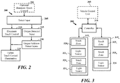
- FIG. 2 depicts a process for operation of a user interface control according to one or more embodiments.
- Process 200 may be employed for control and operation of device using touch control (e.g., touch control 105 ).
- process 200 may provide operation of a touch control.
- Process 200 may be initiated by detecting input to a touch control at block 205.
- input to a touch control detected at block 205 may be an input to at least one touch zone of the touch control.
- the input can include contact to a wrapped surface of the touch control.
- a touch sensor of the touch control detects contact to a wrapped surface of the touch control.
- the touch sensor may be mounted within a housing assembly of the touch control and detect one or more changes in capacitance, deformation, electrical charging, etc.
- input at block 205 may be contact may be sliding contact with a surface of the touch control.
- a sliding contact may adjust temperature or fan speed of a vehicle climate control interface.
- a sliding control may adjust volume or one or more audio settings.
- Input at block 205 may be a slide command to control other settings, such as brightness.
- a touch control device may be configured to illuminate one or more portions of the touch control.
- a controller of the touch control will then control illumination of at least one illumination element of the touch control in response to the input.
- a controller of the touch control outputs a control signal in response to contact with the at least one touch zone. Illumination at block 210 may be in addition to, and/or independently from, output at block 215.
- Process 200 may optionally include illuminating touch zones at block 206 to signal the location of one or more touch zones of the touch control.
- input detected at block 205 may result in updating one or more illumination parameters.
- Illumination patterns can include one or more of brightness, color, partial/full illumination of illumination sources, output type (e.g., pulse, on, etc.).
- touch zones may be illuminated with a low light level which may be later increased in response to a detected input.
- FIG. 3 depicts a graphical representation of device including touch control inputs according to one or more embodiments.
- device 300 relates to a control interface.
- Device 300 may optionally interface with a vehicle control unit 305 to provide one or more selections of the control interface.
- device 300 includes controller 310 and at least one touch control assembly, such as assemblies 315 1-n .
- Device 300 may employed as an input interface for a vehicle system, such as climate or infotainment controls of an automobile or passenger vehicle configuration.
- device 300 may provide one or more control inputs for a vehicle infotainment unit such as vehicle control unit 305.
- system 300 and FIG. 3 refers to a vehicle system, it should be appreciated that other control units may be employed.
- device 300 may provide input controls for one or more devices in general.
- Vehicle control unit 305 may provide one or more of driver assistance, navigation, media, climate control and vehicle control features.
- device 300 includes touch control assemblies 315 1-n which may be used to control one or more functions of device 300.
- touch control assemblies 315 1-n may be used to control one or more functions of device 300.
- the functions controlled by control assemblies 315 1-n are soft functions.
- control assemblies 315 1-n may be hard functions configured to provide a particular function for the device.
- control assemblies 315 1-n may be used to provide climate control inputs.
- device 300 and control assemblies 315 1-n may be configured to provide other functions.
- control assemblies 315 1-n are coupled to controller 310.
- Each control assemblies 315 1-n may be relate to a particular surface or panel. As such, control assemblies 315 1-n may be located in different sections of a user interface.
- Control assemblies 315 1-n are depicted in FIG. 3 as each including a touch zone and light source. According to one embodiment, each touch zone relates to a touch area of an input touch sensor of control assemblies 315 1-n .
- control assembly 315 1 includes touch zones 320 1-n and light sources 321 1-n .
- control assembly 315 n includes touch zones 325 1-n and light source 326.
- device 300 includes control assemblies 315 1-n with multiple assembly units and multiple assembly configurations. It should be appreciated that device 300 may include a single control assembly or more than two assemblies. Controller 310 is configured to detect inputs to one or more of control assemblies 315 1-n and output control signals detected. In certain embodiments, controller 310 may output color or control parameters that may be used by control assemblies 315 1-n to control color output, activation and other functions.
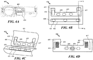
- FIGS. 4A-4D depict graphical representation of touch control assemblies according to one or more embodiments.
- FIG. 4A depicts a graphical representation of a vehicle configuration including a control interface according to one or more embodiments.
- Vehicle system 400 relates to an operator's controls for the vehicle including a display unit 405 and control interface 410.
- FIGs. 4B-4D depict one or more configurations of elements of control interface 410.
- Control interface 410 relates to an interface that may be employed by vehicle system 400.
- control interface 410 relates to a user interface including one or more surfaces. Configurations are provided herein to allow for multiple services which can address vehicle requirements and spacing and allow for positioning of control inputs in accessible locations.
- each surface includes at least one touch zone. Each surface may be associated with a touch control assembly. Each surface may also be associated with a vehicle surface, such as a section or face of a vehicle control console.
- control interface 410 includes control assembly 415 and control assembly 420.
- FIG. 4B depicts control assembly 415 and control assembly 420 in a planar or flat configuration.
- control assemblies and touch control inputs may be associated with curved surfaces.
- Control assembly 415 includes a plurality of touch zones, such as tall touch zones 416, 417, and touch zone 418 on surface 419.
- Control assembly 420 includes a plurality of touch zones, such as touch zone 421, on surface 422. Touch zones of control interface 410 may relate to areas of the interface that may be contacted by a user, wherein the contact is detected when at least a portion of the touch zone is contacted.
- touch zones 418 and 421 may operate similar to a button, wherein contact of the touch zone represents an input.
- Tall touch zones 416, 417 can relate to slider input wherein contact in a portion of the tall touch zone may indicate a desired level.
- sliding inputs to touch zones 416, 417 or motion may represent a degree or sliding input.
- touch zones of control interface 410 are shown by shapes associated with an area where touch may be detected.
- control interface 410 may include a material covering touch zones and the entire control interface such that surfaces 419 and 422 appear as a surface with no contact elements.
- each touch zone of control interface 410 can include one or more light elements that illuminate the touch zone, an area near the touch zone and/or a portion of control interface 410 to indicate an input area.
- the material wrapping control interface 410 may be etched or marked to indicate a touch zone.
- the touch control assemblies may also be controlled to allow for control of vehicle units, such as climate control inputs and functions of a vehicle head unit (e.g., infotainment unit, navigation, unit, user interface display, etc.).
- vehicle units such as climate control inputs and functions of a vehicle head unit (e.g., infotainment unit, navigation, unit, user interface display, etc.).
- tall touch zones 416, 417 may relate to inputs for setting temperature or fan speed of climate controls.
- touch zones of control interface 410 such as touch zones 418 and 421, may be associated with one or more settings of the climate control system.
- touch zones of control assembly 415 may be associated with climate control features while touch zone 420 may be associated with a different function of a vehicle system.
- FIG. 4D depicts a graphical representation of a control interface configuration according to another embodiment.
- control interface 430 relates to a configuration of control assembly 415 according to one embodiment.
- Control interface is shown including one or more touch zones illuminated.
- touch zones may be illuminated in response to detection of a user input.
- illumination of touch zones may be activated in response to vehicle events, such as one or more of vehicle startup, shutdown, etc.
- Control assembly 415 of control interface 430 includes a plurality of touch zones, such as tall touch zones 416, 417, and touch zones 418, 434 on surface 419.
- touch zones of control assembly 415 may each be presented with an illumination element near the location and/or associated with the location of a touch zone.
- tall touch zones 416, 417 are each associated with illumination elements 431, 433 respectively.
- Illumination elements 431, 433 relate to an arrangement of elements that may be illuminated and appear on the surface 419. According to one embodiment, the color of illumination presented may be based on the function associated with touch zones.
- Illumination elements 431 output red light associated with a climate control setting (e.g., heat setting), where illumination elements 433 output blue light associated with another climate control setting (e.g., cooling setting).
- a climate control setting e.g., heat setting
- illumination elements 433 output blue light associated with another climate control setting (e.g., cooling setting).
- the number of elements of illumination elements 431 activated may be based on input settings. For example a user contacting a bottom portion of touch zone 416 may only illuminate the first or lower elements of illumination elements 431. Similarly, a full or extended swipe from the bottom toward the top of touch zone 416 may result in all illumination elements 431 being illuminated.
- touch zones 418, 434 on surface 419 may be illuminated with one or more colors.
- Touch zone 418 is illuminated with a first configuration (e.g., yellow light, etc.) and touch zone 434 is illuminated with a second configuration (e.g., green light, etc.).
- touch zone elements may all be illuminated the same color.
- the color output for each touch zone may change based on function of the control interface, user settings, etc.
- FIG. 4D depicts touch zone elements in an illuminated state.
- one or more touch zones may not be readily perceptible in that the surface of the control interface may not identify the touch zones.
- touch zones may remain in a hidden or secret position until activate by a controller (e.g., controller 310).
- the touch zones may be activated to illuminate each selectable touch zone. Illumination of touch zones may be based on functions or features associated with a user interface. In certain embodiments, the color or position of a touch zone may be identified in a user interface display, such as display unit 405.
- FIGs. 5A-5B depict graphical representations of components of touch controls according to one or more embodiments.
- FIG. 5A depicts a graphical representation of a surface wrapped user interface touch control 500 according to one or more embodiments.
- touch controls as described herein may include one or more elements including a surface wrap to allow for the touch control assembly to be mounted to a main panel, the touch control assembly providing a surface.
- touch control 500 includes wrapping material 505, housing assembly 510, surface 515, touch sensor 520, illumination element 525 and printed wiring board 530. Touch control 500 may be mounted to a main housing 535.
- touch sensor 520 is mounted to an inner surface of the housing assembly 510.
- Touch sensor 520 includes at least one touch zone and is configured to detect contact to outer surface 515 of the housing assembly associated with the at least one touch zone.
- Touch control 500 includes at least one illumination element, such as illumination element 525, configured to illuminate a portion of outer surface 515 of the housing assembly 520 associated the input touch zone.
- Illumination element 525 may represent a light pipe through housing assembly outer surface 515 that allows one or more lighted elements to illuminate a portion of the wrapping.
- Wrapping material 505 may be applied to the outer surface 515 and covers the touch control 500. At least a portion of wrapping material 505 is configured to be illuminated by the at least one illumination element. Wrapping material 505 allows for the outer surface 515 to be wrapped in a soft material like a polyurethane, leather, suede or fabric. The appearance of wrapping material 505 allows for the surface to appear uninterrupted and seamless. When prompted, wrapping material 505 and touch control 500 come to life with backlighting from illumination element 525. Wrapping material 505 may include subtle surface marking from embossed to laser marked icons. The configurations provide a solution for maintaining uninterrupted design while providing functional accessibility to common controls.
- Printed wiring board 530 may include a controller coupled to touch sensor 520 and illumination element 525.
- the controller is configured to illuminate the at least one illumination element in response to contact with the at least one touch zone, and output a control signal in response to contact with the at least one touch zone.
- FIG. 5A Elements of FIG. 5A are shown in a flat configuration but may be configured in a curved arrangement similar to FIG. 4C or as in the assemblies shown in FG. 5B.
- FIG. 5B depicts a graphical representation of a surface wrapped user interface touch control configuration according to one or more embodiments.
- Touch control 550 includes two assemblies. Assembly 551 is mounted in a lower position and includes elements similar to touch control 500.
- Assembly 551 may be bonded to main panel 535 which may be fiber glass, 3D printed material, molded plastic etc.
- Main panel 535 may relate to a console of a vehicle control interface.
- Assembly 551 includes housing assembly 510 which may be a sub-bezel supporting touch sensor 520.
- Assembly 552 may be bonded to main panel 535 and include elements similar to touch control 500.
- the touch control of assembly 553 includes a sheet material 556 (e.g., acrylic sheet, etc.) that may be bonded to a touch sensor 557 and wrap material.
- Sheet material 556 may be a translucent material that is mounted to a sub-bezel to support the touch sensor.
- Sheet material 556 may be mounted to the main panel 535.
- wrapping material may cover assembly 551, assembly 552 and main panel 535.
Landscapes
- Engineering & Computer Science (AREA)
- General Engineering & Computer Science (AREA)
- Theoretical Computer Science (AREA)
- Human Computer Interaction (AREA)
- General Physics & Mathematics (AREA)
- Physics & Mathematics (AREA)
- Mechanical Engineering (AREA)
- Chemical & Material Sciences (AREA)
- Transportation (AREA)
- Combustion & Propulsion (AREA)
- Computer Networks & Wireless Communication (AREA)
- User Interface Of Digital Computer (AREA)
- Circuit Arrangement For Electric Light Sources In General (AREA)
- Arrangements Of Lighting Devices For Vehicle Interiors, Mounting And Supporting Thereof, Circuits Therefore (AREA)
- Switches That Are Operated By Magnetic Or Electric Fields (AREA)
- Arrangement Of Elements, Cooling, Sealing, Or The Like Of Lighting Devices (AREA)
Abstract
Description
- The present disclosure relates to user interface control elements, and more particularly to a surface wrapped user interface touch control and methods of using same.
- Modern devices use a variety of control means to detect operational commands. There exists a need to improve upon the conventional control interface elements, such as simple push buttons and control knobs. In some cases for example, the structure of conventional units impose structural requirements on a device. By way of further example, conventional push button switches may require an elevated or silo structure to allow for the button to be pressed. In many cases, the structure of the conventional buttons do not allow for the buttons or input elements to be covered or wrapped by other materials. Typical push button elements are accompanied by a label or symbol identifying operation of the button.
- Product designers are often faced with the task of designing control interfaces with a particular appearance. Often, new designs require advances in technology and component design to accommodate desired interface details. In the automotive industry, for example, many manufacturers develop new control interface layouts with new models and model refreshes. Due to one or more considerations, such as spacing, layout and weight, existing control interfaces do not meet the requirements of new designs. In many cases, changing size and shape of conventional buttons does not allow for the desired interface. In addition, functions of control interfaces change with advances in vehicle technology and function. There exists a desire for control interface elements that allows for use in a vehicle control interfaces and for device interfaces in general.
- Disclosed and claimed herein are methods, configurations and devices for touch control. One embodiment is directed to a touch control device including a housing assembly including an outer surface, and a touch sensor mounted to an inner surface of the housing assembly. The touch sensor includes at least one touch zone and the touch sensor is configured to detect contact to the outer surface of the housing assembly associated with the at least one touch zone. The touch control device also includes at least one illumination element configured to illuminate a portion of the outer surface of the housing assembly associated with the at least one touch zone. The touch control device also includes a controller coupled to the touch sensor and the at least one illumination element. The controller is configured to illuminate the at least one illumination element in response to contact with the at least one touch zone, and output a control signal in response to contact with the at least one touch zone.
- In one embodiment, the outer surface is a flat surface.
- In one embodiment, the outer surface is a curved surface.
- In one embodiment, the housing assembly mounts to a main panel and the touch control device and main panel are wrapped in a material.
- In one embodiment, the touch sensor includes a plurality of touch zones.
- In one embodiment, the illumination element includes at least one light source and at least one illumination area of the surface.
- In one embodiment, the controller is mounted to the housing assembly and is configured to output touch commands detected by the touch sensor.
- In one embodiment, the touch sensor includes at least one illumination element for each of the plurality of touch zones.
- In one embodiment, the touch sensor includes a light tube for each touch zone, wherein the light tube is configured to be illuminated and controlled to present one or more colors by the controller.
- One embodiment is directed to a method for operation of a touch control including detecting, by a touch control, an input to at least one touch zone of the touch control, wherein the input includes contact to a wrapped surface of the touch control. The method also includes controlling, by a controller of the touch control, illumination of at least one illumination element of the touch control in response to the input, and outputting, by a controller of the touch control, a control signal in response to contact with the at least one touch zone.
- In one embodiment, the method includes illuminating at least one touch zone to signal the location of one or more touch zones of the touch control.
- In one embodiment, the method includes updating at least one illumination parameters. In certain embodiments, touch zones may be illuminated with a light level increased in response to a detected input.
- One embodiment is directed to a surface wrapped touch control device including a housing assembly supporting an outer surface for a touch control and a touch sensor mounted to an inner surface of the housing assembly. The touch sensor includes at least one touch zone and the touch sensor is configured to detect contact to the outer surface of the housing assembly associated with the at least one touch zone. The surface wrapped touch control device also includes at least one illumination element configured to illuminate a portion of the outer surface of the housing assembly associated the at least one touch zone. The surface wrapped touch control device also includes a wrapping material applied to the outer surface and covering the touch sensor, wherein the wrapping material is configured to be illuminated by the at least one illumination element. The surface wrapped touch control device also includes a controller coupled to the touch sensor and the at least one illumination element, wherein the controller is configured to illuminate the at least one illumination element in response to contact with the at least one touch zone, and output a control signal in response to contact with the at least one touch zone.
- In one embodiment, the outer surface is at least one of a flat and curved surface covered by the wrapping material.
- In one embodiment, the housing assembly mounts to a main panel and the touch control device and main panel are wrapped in a material.
- In one embodiment, the touch sensor includes a plurality of touch zones.
- In one embodiment, the illumination element includes at least one light source and at least one illumination area of the surface.
- In one embodiment, the controller is mounted to the housing assembly and is configured to output touch commands detected by the touch sensor.
- In one embodiment, the touch sensor includes at least one illumination element for each of the plurality of touch zones.
- In one embodiment, the touch sensor includes a light tube for each touch zone, wherein the light tube is configured to be illuminated and controlled to present one or more colors by the controller.
- Other aspects, features, and techniques will be apparent to one skilled in the relevant art in view of the following detailed description of the embodiments.
- The features, objects, and advantages of the present disclosure will become more apparent from the detailed description set forth below when taken in conjunction with the drawings in which like reference characters identify correspondingly throughout and wherein:
-
FIG. 1 depicts operation of a user interface control according to one or more embodiments; -
FIG. 2 depicts a process for operation of a touch control according to one or more embodiments; -
FIG. 3 depicts a graphical representation of a device including touch control inputs according to one or more embodiments; -
FIG. 4A depicts a graphical representation of a vehicle configuration including a control interface according to one or more embodiments; -
FIG. 4B depicts a graphical representation of a control interface configuration according to one or more embodiments; -
FIG. 4C depicts a graphical representation of a control interface configuration according to another embodiment; -
FIG. 4D depicts a graphical representation of a control interface configuration according to another embodiment; -
FIG. 5A depicts a graphical representation of a surface wrapped user interface touch control according to one or more embodiments; and -
FIG. 5B depicts a graphical representation of a surface wrapped user interface touch control configuration according to one or more embodiments. - One aspect of the disclosure is directed to user interface touch controls and operation. In one embodiment, a surface wrapped touch control is provided including a material wrapping a surface and covering one or more sensing zones. The touch control is configured to illuminate one or more portions of the surface. The touch control is configured to provide one or more of a touch detection and slider operation. In that fashion, zones of the touch control may be contacted and operate as input elements. At least one of the touch sensing, illumination, and touch control structure are configured to allow for a material to wrap a surface of the touch control. Configurations and devices described herein may relate to flat and curved surfaces.
- One embodiment is directed to an assembly for a vehicle. In another embodiment, vehicle configurations are provided including one or more surfaces having at least one touch zone. The one or more assemblies of the touch control may be associated with a plurality of vehicle surfaces. The touch control assemblies may also be controlled to allow for control of vehicle units, such as climate control inputs and functions of a vehicle head unit (e.g., infotainment unit, navigation, unit, user interface display, etc.).
- Embodiments are also directed to operation and control of user interface touch controls. By way of example, one or more illumination settings may be controlled to provide a feedback to a user. In addition, illumination settings and configurations of the touch control allow for a surface of the touch control to appear as a smooth surface while also allowing for contact with one or more touch zones. Illumination of the surface can provide notifications of detected contact. Embodiments and configurations discussed herein provide can allow for maintaining uninterrupted design while providing functional accessibility to common controls.
- Although device configurations are discussed herein with respect to vehicle control and vehicle applications, it should be appreciated that touch control units may be applied to other devices and for additional applications.
- As used herein, the terms "a" or "an" shall mean one or more than one. The term "plurality" shall mean two or more than two. The term "another" is defined as a second or more. The terms "including" and/or "having" are open ended (e.g., comprising). The term "or" as used herein is to be interpreted as inclusive or meaning any one or any combination. Therefore, "A, B or C" means "any of the following: A; B; C; A and B; A and C; B and C; A, B and C". An exception to this definition will occur only when a combination of elements, functions, steps or acts are in some way inherently mutually exclusive.
- Reference throughout this document to "one embodiment," "certain embodiments," "an embodiment," or similar term means that a particular feature, structure, or characteristic described in connection with the embodiment is included in at least one embodiment. Thus, the appearances of such phrases in various places throughout this specification are not necessarily all referring to the same embodiment. Furthermore, the particular features, structures, or characteristics may be combined in any suitable manner on one or more embodiments without limitation.
-
FIG. 1 depicts operation of a user interface control according to one or more embodiments. According to one embodiment, a touch control device is provided including a surface and one or more elements to detect contact with the surface. Embodiments are also directed to operation and control of user interface touch controls. By way of example, one or more illumination settings may be controlled to provide a feedback to a user. In addition, illumination settings and configurations of the touch control allow for a surface of the touch control to appear as a smooth surface while also allowing for contact with one or more touch zones. Illumination of the surface can provide notifications of detected contact. Embodiments and configurations discussed herein provide can allow for maintaining uninterrupted design while providing functional accessibility to common controls. -
Touch control 100 may be a surface wrapped touch control including a material wrapping anouter surface 105 of the touch control and covering one or more sensing zones.Touch control 100 may be configured to illuminate one or more portions ofsurface 105.Touch control 100 may also provide one or more of a touch detection and slider operation. In that fashion, zones oftouch control 100 may be contacted and operate as input elements. At least one of the touch sensing, illumination, and touch control structure are configured to allow for a material to wrap a surface of the touch control. Configurations and devices described herein may relate to flat and curved surfaces. - In one embodiment, contact with zones or particular touch zones of the surface may be detected by touch sensors mounted within the touch control device.
Touch control 100 includessurface 105 and at least one touch zone shown as 110 inFIG. 1 . According to one embodiment of the disclosure,touch control 100 includes a touch sensor (e.g., film touch sensor, capacitive touch sensor, flexible touch sensor, etc.) having at least one touch zone and one or more structural elements such as a sub-bezel or housing providing an outer surface. The touch sensor oftouch control 100 may be mounted to an inner surface of the housing assembly. In that fashion, the touch sensor is configured to detect contact to the outer surface of the housing assembly associated with the at least one touch zone. In certain embodiments,touch control 100 may include a housing assembly or sub bezel holding a sheet or formed material, wherein the touch sensor is mounted to an inner surface of the sheet material. The housing and sensor oftouch control 100 allow for a user interface that detects touch but does not require buttons or other control inputs mounted to the outside of the housing. In that fashion,touch control 100 may be wrapped in a material that allows for the inputs to appear as part of the surface of the interface. In certain embodiments, the wrapped material may be etched or embossed to indicate touch zones and/or functionalities associated with the touch zone. By way of example, a touch zone associated with climate control for a vehicle may include an up arrow, down arrow and letters "TEMP" such that location of the up and down arrows is associated with touch zones. The actual touch zones of the touch sensor may be hidden from view allowing for the housing material to protect the sensor. In addition to protections the sensor, the configurations descried herein allow for curved surfaces to be utilized as input surfaces. - In one embodiment, the housing assembly of
touch control 100 provides an outer surface that may be wrapped, wherein contact to the outer surface and/or wrapped outer surface may be detected. The housing assembly oftouch control 100 may mount to a main panel and the touch control device and the main panel may both be wrapped in a material. The outer surface is shown assurface 105 inFIG. 1 , which may include one or more touch zones.Surface 105 may be part of a housing assembly associated withtouch control 100. In one embodiment,surface 105 oftouch control 100 may be a flat surface. In one embodiment,surface 105 oftouch control 100 may be a curved surface. - According to one embodiment,
touch control 100 includes at least one illumination element configured to illuminate a portion of the outer surface of the housing assembly associated at least one touch zone.Touch control 100 may also include a controller coupled to the touch sensor and the at least one illumination element. The controller may be configured to illuminate the at least one illumination element in response to contact with the at least one touch zone. The controller may also be configured to output a control signal in response to contact with the at least one touch zone. - According to one embodiment,
surface 105 may be illuminated to one or more states, ranging from no illumination to illumination of all elements ofsurface 105.State 115 is depicted where no elements are illuminated. A user input is shown by 120, making contact withtouch zone 110 represented asstate 121. -
Touch control 100 may configured to detect contact fromuser 120, as shown bystate 121. In response to the contact,touch control 100 may perform one or more operations. In one embodiment,touch control 100 may illuminate a portion ofsurface 105. Instate 122,glow 125 is emitted. Glow 125 may be from behind a wrapped material ofsurface 105 oftouch control 100. Glow 125 shows illumination output bytouch control 100. - Following
state 121,touch control 100 may be configured to detect contact fromuser 120, as shown bystate 123. In response to the contact,touch control 100 may perform one or more operations including illumination of all touch zones includingtouch zones 1301-n . The touch sensor oftouch control 100 can include at least one illumination element for each of the plurality oftouch zones 1301-n andtouch zone 110. By way of further example,touch control 100 may include a light tube for each oftouch zone 110 andtouch zones 1301-n . Each of the light tubes can be configured to be illuminated and controlled to present one or more colors by the controller. In one embodiment, illumination of all touch zones may be in response to vehicle start up or other vehicle events such as activation of vehicle head lamps. -
Touch control 100 allows for a surface that can accommodate vehicle and other device constraints such as a flat or curved surface without requiring a conventional pushbutton switch. As will be discussed herein, the configurations allow for detection and feedback through illumination of contact with input terminals. The configurations allow for input terminals without physical pushbutton presses which move the button into a different position. In contrast,touch control 100 allows for mere contact, such as a touch or tap, to be read as an indication of an input control. Also in contrast to conventional input terminals,touch control 100 does not require for buttons to rise up or be pushed into the structure. As such,touch control 100 described herein are not subject to the buttons which may wear out due to repeated use and button wear. -
FIG. 2 depicts a process for operation of a user interface control according to one or more embodiments.Process 200 may be employed for control and operation of device using touch control (e.g., touch control 105). In certain embodiments,process 200 may provide operation of a touch control.Process 200 may be initiated by detecting input to a touch control atblock 205. In one embodiment, input to a touch control detected atblock 205 may be an input to at least one touch zone of the touch control. The input can include contact to a wrapped surface of the touch control. In certain embodiments, a touch sensor of the touch control detects contact to a wrapped surface of the touch control. The touch sensor may be mounted within a housing assembly of the touch control and detect one or more changes in capacitance, deformation, electrical charging, etc. - In certain embodiments, input at
block 205 may be contact may be sliding contact with a surface of the touch control. With respect to vehicle configurations, a sliding contact may adjust temperature or fan speed of a vehicle climate control interface. Alternatively, a sliding control may adjust volume or one or more audio settings. Input atblock 205 may be a slide command to control other settings, such as brightness. - Based on the input detected at
block 205, a touch control device may be configured to illuminate one or more portions of the touch control. Atblock 210, a controller of the touch control will then control illumination of at least one illumination element of the touch control in response to the input. Atblock 215, a controller of the touch control outputs a control signal in response to contact with the at least one touch zone. Illumination atblock 210 may be in addition to, and/or independently from, output atblock 215. - In certain embodiments, multiple input commands may be detected. For example slider operations, repeated presses, etc. Additional inputs detected may be output at
block 220. Atblock 225 illumination of the touch control may be updated. Illumination may be updated atblock 225 based on time, after period of time the light control turns off. In other embodiments, illumination may be updated atblock 225 to indicate position of a slide control. -
Process 200 may optionally include illuminating touch zones atblock 206 to signal the location of one or more touch zones of the touch control. As such, input detected atblock 205 may result in updating one or more illumination parameters. Illumination patterns can include one or more of brightness, color, partial/full illumination of illumination sources, output type (e.g., pulse, on, etc.). In certain embodiments, touch zones may be illuminated with a low light level which may be later increased in response to a detected input. -
FIG. 3 depicts a graphical representation of device including touch control inputs according to one or more embodiments. According to one embodiment,device 300 relates to a control interface.Device 300 may optionally interface with avehicle control unit 305 to provide one or more selections of the control interface. According to oneembodiment device 300 includescontroller 310 and at least one touch control assembly, such asassemblies 3151-n .Device 300 may employed as an input interface for a vehicle system, such as climate or infotainment controls of an automobile or passenger vehicle configuration. According to one embodiment,device 300 may provide one or more control inputs for a vehicle infotainment unit such asvehicle control unit 305. Althoughsystem 300 andFIG. 3 refers to a vehicle system, it should be appreciated that other control units may be employed. By way example,device 300 may provide input controls for one or more devices in general. -
Vehicle control unit 305 may provide one or more of driver assistance, navigation, media, climate control and vehicle control features. In one embodiment,device 300 includestouch control assemblies 3151-n which may be used to control one or more functions ofdevice 300. In the vehicle example, may be configured to provide inputs associated with a function ofvehicle control unit 305, such as selection of a source (e.g., navigation, climate control, audio settings, media playback, etc.), or control of the source functions. As such, the functions controlled bycontrol assemblies 3151-n are soft functions. In other embodiments,control assemblies 3151-n may be hard functions configured to provide a particular function for the device. In one exemplary embodiment,control assemblies 3151-n may be used to provide climate control inputs. However, it should be appreciated thatdevice 300 andcontrol assemblies 3151-n may be configured to provide other functions. - As shown in
FIG. 3 ,control assemblies 3151-n are coupled tocontroller 310. Eachcontrol assemblies 3151-n may be relate to a particular surface or panel. As such,control assemblies 3151-n may be located in different sections of a user interface.Control assemblies 3151-n are depicted inFIG. 3 as each including a touch zone and light source. According to one embodiment, each touch zone relates to a touch area of an input touch sensor ofcontrol assemblies 3151-n . InFIG. 3 ,control assembly 3151 includestouch zones 3201-n andlight sources 3211-n. Similarly,control assembly 315n includestouch zones 3251-n andlight source 326. According to one embodiment, light sources ofdevice 300 relate to individual output sources of light, such as a light tube (e.g., guide) that may be illuminated and controlled to present one or more colors. According to one embodiment, each touch zone oftouch zones 3251-n may be configured to include a light tube. In another embodiment, each light source relates to a multiple element display which may allow for display of a slider control, such as a column of horizontal bar elements that illuminates one or more bars based on slider position. - According to one embodiment,
device 300 includescontrol assemblies 3151-n with multiple assembly units and multiple assembly configurations. It should be appreciated thatdevice 300 may include a single control assembly or more than two assemblies.Controller 310 is configured to detect inputs to one or more ofcontrol assemblies 3151-n and output control signals detected. In certain embodiments,controller 310 may output color or control parameters that may be used bycontrol assemblies 3151-n to control color output, activation and other functions. -
FIGS. 4A-4D depict graphical representation of touch control assemblies according to one or more embodiments.FIG. 4A depicts a graphical representation of a vehicle configuration including a control interface according to one or more embodiments.Vehicle system 400 relates to an operator's controls for the vehicle including adisplay unit 405 andcontrol interface 410.FIGs. 4B-4D depict one or more configurations of elements ofcontrol interface 410. - Referring now to
FIG. 4B , a graphical representation is shown of a configuration ofcontrol interface 410 according to one or more embodiments.Control interface 410 relates to an interface that may be employed byvehicle system 400. According to one embodiment,control interface 410 relates to a user interface including one or more surfaces. Configurations are provided herein to allow for multiple services which can address vehicle requirements and spacing and allow for positioning of control inputs in accessible locations. According to one embodiment, each surface includes at least one touch zone. Each surface may be associated with a touch control assembly. Each surface may also be associated with a vehicle surface, such as a section or face of a vehicle control console. - According to one embodiment,
control interface 410 includescontrol assembly 415 andcontrol assembly 420.FIG. 4B depictscontrol assembly 415 andcontrol assembly 420 in a planar or flat configuration. However, as will be discussed below with respect toFIG. 4C , control assemblies and touch control inputs may be associated with curved surfaces.Control assembly 415 includes a plurality of touch zones, such astall touch zones touch zone 418 onsurface 419.Control assembly 420 includes a plurality of touch zones, such astouch zone 421, onsurface 422. Touch zones ofcontrol interface 410 may relate to areas of the interface that may be contacted by a user, wherein the contact is detected when at least a portion of the touch zone is contacted. According to one embodiment,touch zones Tall touch zones zones - According to one embodiment, touch zones of
control interface 410 are shown by shapes associated with an area where touch may be detected. However, according to one embodiment,control interface 410 may include a material covering touch zones and the entire control interface such that surfaces 419 and 422 appear as a surface with no contact elements. In certain embodiments and as described herein, each touch zone ofcontrol interface 410 can include one or more light elements that illuminate the touch zone, an area near the touch zone and/or a portion ofcontrol interface 410 to indicate an input area. In certain embodiments, the materialwrapping control interface 410 may be etched or marked to indicate a touch zone. - According to one embodiment, the touch control assemblies may also be controlled to allow for control of vehicle units, such as climate control inputs and functions of a vehicle head unit (e.g., infotainment unit, navigation, unit, user interface display, etc.). According to one embodiment,
tall touch zones control interface 410, such astouch zones control assembly 415 may be associated with climate control features whiletouch zone 420 may be associated with a different function of a vehicle system. -
FIG. 4C depicts a graphical representation of a control interface configuration according to another embodiment.Control interface 410 is shown inFIG. 4C withcontrol assembly 415 andcontrol assembly 420 including a plurality of touch zones and wherein thesurface 425 ofcontrol assembly 415 andsurface 426 ofcontrol assembly 420 are associated with a curved surface. Components ofcontrol interface 410 allow for control assemblies to be formed with a curved surface and still allow for touch control. In addition to allowing for an aesthetic configuration to be provided, the curved configuration can accommodate vehicle packaging constraints and solves one or more deficiencies associated requiring larger space for flush or flat mount buttons. In addition to accommodating different vehicle types, touch zones may be provided that allow contact or touch on surfaces that do not support conventional sensors.Control interface 410 includes a plurality of touch zones such astall touch zones touch zone 418 onsurface 425.Control assembly 420 includes a plurality of touch zones, such astouch zone 421, onsurface 426. -
FIG. 4D depicts a graphical representation of a control interface configuration according to another embodiment. According to one embodiment,control interface 430 relates to a configuration ofcontrol assembly 415 according to one embodiment. Control interface is shown including one or more touch zones illuminated. According to one embodiment, touch zones may be illuminated in response to detection of a user input. According to another embodiment, illumination of touch zones may be activated in response to vehicle events, such as one or more of vehicle startup, shutdown, etc. -
Control assembly 415 ofcontrol interface 430 includes a plurality of touch zones, such astall touch zones touch zones surface 419. According to one embodiment touch zones ofcontrol assembly 415 may each be presented with an illumination element near the location and/or associated with the location of a touch zone. By way of example,tall touch zones illumination elements Illumination elements surface 419. According to one embodiment, the color of illumination presented may be based on the function associated with touch zones.Illumination elements 431 output red light associated with a climate control setting (e.g., heat setting), whereillumination elements 433 output blue light associated with another climate control setting (e.g., cooling setting). According to one embodiment the number of elements ofillumination elements 431 activated may be based on input settings. For example a user contacting a bottom portion oftouch zone 416 may only illuminate the first or lower elements ofillumination elements 431. Similarly, a full or extended swipe from the bottom toward the top oftouch zone 416 may result in allillumination elements 431 being illuminated. - According to one embodiment,
touch zones surface 419 may be illuminated with one or more colors.Touch zone 418 is illuminated with a first configuration (e.g., yellow light, etc.) andtouch zone 434 is illuminated with a second configuration (e.g., green light, etc.). In certain embodiments, touch zone elements may all be illuminated the same color. In other embodiments, the color output for each touch zone may change based on function of the control interface, user settings, etc. -
FIG. 4D depicts touch zone elements in an illuminated state. According to one embodiment, one or more touch zones may not be readily perceptible in that the surface of the control interface may not identify the touch zones. According to one embodiment, touch zones may remain in a hidden or secret position until activate by a controller (e.g., controller 310). In other embodiments, the touch zones may be activated to illuminate each selectable touch zone. Illumination of touch zones may be based on functions or features associated with a user interface. In certain embodiments, the color or position of a touch zone may be identified in a user interface display, such asdisplay unit 405. -
FIGs. 5A-5B depict graphical representations of components of touch controls according to one or more embodiments.FIG. 5A depicts a graphical representation of a surface wrapped userinterface touch control 500 according to one or more embodiments. According to one embodiment, touch controls as described herein may include one or more elements including a surface wrap to allow for the touch control assembly to be mounted to a main panel, the touch control assembly providing a surface. - According to one embodiment,
touch control 500 includes wrappingmaterial 505,housing assembly 510,surface 515,touch sensor 520,illumination element 525 and printedwiring board 530.Touch control 500 may be mounted to amain housing 535. -
Housing assembly 510 supportssurface 515, which may provide an outer surface for mountingwrapping material 505 and for providing a touch surface. - In one embodiment,
touch sensor 520 is mounted to an inner surface of thehousing assembly 510.Touch sensor 520 includes at least one touch zone and is configured to detect contact toouter surface 515 of the housing assembly associated with the at least one touch zone. -
Touch control 500 includes at least one illumination element, such asillumination element 525, configured to illuminate a portion ofouter surface 515 of thehousing assembly 520 associated the input touch zone.Illumination element 525 may represent a light pipe through housing assemblyouter surface 515 that allows one or more lighted elements to illuminate a portion of the wrapping. - Wrapping
material 505 may be applied to theouter surface 515 and covers thetouch control 500. At least a portion of wrappingmaterial 505 is configured to be illuminated by the at least one illumination element. Wrappingmaterial 505 allows for theouter surface 515 to be wrapped in a soft material like a polyurethane, leather, suede or fabric. The appearance of wrappingmaterial 505 allows for the surface to appear uninterrupted and seamless. When prompted, wrappingmaterial 505 andtouch control 500 come to life with backlighting fromillumination element 525. Wrappingmaterial 505 may include subtle surface marking from embossed to laser marked icons. The configurations provide a solution for maintaining uninterrupted design while providing functional accessibility to common controls. - Printed
wiring board 530 may include a controller coupled totouch sensor 520 andillumination element 525. The controller is configured to illuminate the at least one illumination element in response to contact with the at least one touch zone, and output a control signal in response to contact with the at least one touch zone. - Elements of
FIG. 5A are shown in a flat configuration but may be configured in a curved arrangement similar toFIG. 4C or as in the assemblies shown in FG. 5B. -
FIG. 5B depicts a graphical representation of a surface wrapped user interface touch control configuration according to one or more embodiments.Touch control 550 includes two assemblies.Assembly 551 is mounted in a lower position and includes elements similar totouch control 500. -
Assembly 551 may be bonded tomain panel 535 which may be fiber glass, 3D printed material, molded plastic etc.Main panel 535 may relate to a console of a vehicle control interface.Assembly 551 includeshousing assembly 510 which may be a sub-bezel supportingtouch sensor 520. -
Assembly 552 may be bonded tomain panel 535 and include elements similar totouch control 500. According to one embodiment, the touch control of assembly 553 includes a sheet material 556 (e.g., acrylic sheet, etc.) that may be bonded to atouch sensor 557 and wrap material.Sheet material 556 may be a translucent material that is mounted to a sub-bezel to support the touch sensor.Sheet material 556 may be mounted to themain panel 535. According to one embodiment, wrapping material may coverassembly 551,assembly 552 andmain panel 535. - While this disclosure has been particularly shown and described with references to exemplary embodiments thereof, it will be understood by those skilled in the art that various changes in form and details may be made therein without departing from the scope of the claimed embodiments.
Claims (15)
- A touch control device (100, 500) comprising:a housing assembly (510) including an outer surface (515);a touch sensor (520) mounted to an inner surface of the housing assembly (510), wherein the touch sensor (520) includes at least one touch zone and wherein the touch sensor is configured to detect contact to the outer surface (515) of the housing assembly associated with the at least one touch zone;at least one illumination element (525) configured to illuminate a portion of the outer surface (515) of the housing assembly associated with the at least one touch zone; anda controller coupled to the touch sensor (520) and the at least one illumination element (525), wherein the controller is configured toilluminate the at least one illumination element (525) in response to contact with the at least one touch zone (520), andoutput a control signal in response to contact with the at least one touch zone.
- The touch control device (100, 500) of claim 1, wherein the outer surface is a flat surface.
- The touch control device (100, 500) of claim 1, wherein the outer surface is a curved surface.
- The touch control device (100, 500) of any of the preceding claims, wherein the housing assembly (510) mounts to a main panel and the touch control device and main panel are wrapped in a material.
- The touch control device (100, 500) of any of the preceding claims, wherein the touch sensor (520) includes a plurality of touch zones.
- The touch control device (100, 500) of any of the preceding claims, wherein the illumination element (525) includes at least one light source and at least one illumination area of the surface.
- The touch control device (100, 500) of any of the preceding claims, wherein the controller is mounted to the housing assembly (510) and is configured to output touch commands detected by the touch sensor (520).
- The touch control device (100, 500) of any of the preceding claims, wherein the touch sensor (520) includes at least one illumination element (525) for each of the plurality of touch zones.
- The touch control device (100, 500) of any of the preceding claims, wherein the touch sensor (520) includes a light tube for each touch zone, wherein the light tube is configured to be illuminated and controlled to present one or more colors by the controller.
- A method for operation of a touch control, the method comprising:detecting, by a touch control, an input to at least one touch zone of the touch control, wherein the input includes contact to a wrapped surface of the touch control;controlling, by a controller of the touch control, illumination of at least one illumination element of the touch control in response to the input; andoutputting, by a controller of the touch control, a control signal in response to contact with the at least one touch zone.
- The method claim 10, further comprising include illuminating at least one touch zone to signal the location of one or more touch zones of the touch control.
- The method claim 10 or 11, further comprising updating at least one illumination parameter, wherein touch zones may be illuminated with a light level increased in response to a detected input.
- A surface wrapped touch control device comprising:a housing assembly (510) supporting an outer surface for a touch control;a touch sensor (520) mounted to an inner surface of the housing assembly, wherein the touch sensor includes at least one touch zone and wherein the touch sensor is configured to detect contact to the outer surface of the housing assembly associated with the at least one touch zone;at least one illumination element (525) configured to illuminate a portion of the outer surface of the housing assembly associated the at least one touch zone;a wrapping material applied to the outer surface and covering the touch sensor, wherein the wrapping material is configured to be illuminated by the at least one illumination element; anda controller coupled to the touch sensor and the at least one illumination element (525), wherein the controller is configured toilluminate the at least one illumination element (525) in response to contact with the at least one touch zone, andoutput a control signal in response to contact with the at least one touch zone.
- The surface wrapped touch control device of claim 13, wherein the illumination element includes at least one light source and at least one illumination area of the surface.
- The surface wrapped touch control device of claim 14, wherein the touch sensor includes a light tube for each touch zone, wherein the light tube is configured to be illuminated and controlled to present one or more colors by the controller.
Applications Claiming Priority (1)
| Application Number | Priority Date | Filing Date | Title |
|---|---|---|---|
| US201762597931P | 2017-12-12 | 2017-12-12 |
Publications (2)
| Publication Number | Publication Date |
|---|---|
| EP3498517A1 true EP3498517A1 (en) | 2019-06-19 |
| EP3498517B1 EP3498517B1 (en) | 2021-04-21 |
Family
ID=64959097
Family Applications (1)
| Application Number | Title | Priority Date | Filing Date |
|---|---|---|---|
| EP18211819.0A Active EP3498517B1 (en) | 2017-12-12 | 2018-12-12 | Touch control device and method for operating the same |
Country Status (4)
| Country | Link |
|---|---|
| US (1) | US10901609B2 (en) |
| EP (1) | EP3498517B1 (en) |
| KR (1) | KR102662152B1 (en) |
| CN (1) | CN110018749B (en) |
Families Citing this family (5)
| Publication number | Priority date | Publication date | Assignee | Title |
|---|---|---|---|---|
| US11137896B2 (en) | 2019-12-17 | 2021-10-05 | Harman International Industries, Incorporated | System and method for determining a location of a user relative to a user interface for contextual control |
| KR102378857B1 (en) * | 2021-10-29 | 2022-03-24 | 주식회사 서연이화 | Haptic Generator for Panels of Vehicles and Interior Panel for Vehicles using thereof |
| CN115394577B (en) * | 2022-10-26 | 2023-02-28 | 珠海翔翼航空技术有限公司 | Deep water key switch based on specific touch gesture and control method thereof |
| CN121752979A (en) * | 2023-07-03 | 2026-03-27 | 胶视公司 | Systems and methods for haptic intelligence |
| KR20250102570A (en) * | 2023-12-28 | 2025-07-07 | 현대모비스 주식회사 | Cockpit system with operating system using projector |
Citations (3)
| Publication number | Priority date | Publication date | Assignee | Title |
|---|---|---|---|---|
| US20090058118A1 (en) * | 2007-08-31 | 2009-03-05 | Lear Corporation | Trim panel for a motor vehicle and method of manufacturing |
| EP2208645A1 (en) * | 2009-01-14 | 2010-07-21 | Sellner GmbH | Trim with sensor |
| EP3372437A1 (en) * | 2017-03-06 | 2018-09-12 | LG Electronics Inc. | User interface apparatus for vehicle, method of manufacturing user interface apparatus, and vehicle |
Family Cites Families (13)
| Publication number | Priority date | Publication date | Assignee | Title |
|---|---|---|---|---|
| US6652128B2 (en) * | 2001-01-31 | 2003-11-25 | Textron Automotive Company, Inc. | Backlighting method for an automotive trim panel |
| KR100985496B1 (en) * | 2008-07-01 | 2010-10-05 | 동아대학교 산학협력단 | Device and method for controlling function of vehicle using touch pad module |
| US20110002138A1 (en) * | 2009-07-02 | 2011-01-06 | International Automotive Components Group North America, Inc. | Selectively illuminated trim panels |
| KR20120059272A (en) * | 2010-11-30 | 2012-06-08 | 현대자동차주식회사 | Input device of touch panel type for car |
| US9766734B2 (en) * | 2013-02-20 | 2017-09-19 | Nvidia Corporation | Synchronized touch input recognition |
| US9417791B2 (en) * | 2013-03-29 | 2016-08-16 | Deere & Company | Active feedback interface for touch screen display |
| KR101484229B1 (en) * | 2013-07-24 | 2015-01-16 | 현대자동차 주식회사 | Touch display device for vehicle and driving method thereof |
| JP2015130168A (en) * | 2013-12-31 | 2015-07-16 | イマージョン コーポレーションImmersion Corporation | Friction augmented control, and method to convert buttons of touch control panels to friction augmented controls |
| FR3016839B1 (en) * | 2014-01-27 | 2017-06-09 | Faurecia Interieur Ind | VEHICLE CLUTCH ELEMENT |
| FR3019110B1 (en) * | 2014-03-28 | 2018-03-30 | Faurecia Interieur Industrie | VEHICLE TRIM MEMBER |
| DE102014215329A1 (en) * | 2014-08-04 | 2016-02-04 | Volkswagen Aktiengesellschaft | Ambient light unit and method for adjusting an ambient light in a vehicle |
| KR20170074740A (en) * | 2015-12-22 | 2017-06-30 | 엘지전자 주식회사 | User interface apparatus for vehicle and vehicle |
| KR101796991B1 (en) * | 2016-03-04 | 2017-11-13 | 현대자동차주식회사 | Vehicle and method of controlling thereof |
-
2018
- 2018-12-11 US US16/216,465 patent/US10901609B2/en active Active
- 2018-12-12 EP EP18211819.0A patent/EP3498517B1/en active Active
- 2018-12-12 CN CN201811518399.7A patent/CN110018749B/en active Active
- 2018-12-12 KR KR1020180160249A patent/KR102662152B1/en active Active
Patent Citations (3)
| Publication number | Priority date | Publication date | Assignee | Title |
|---|---|---|---|---|
| US20090058118A1 (en) * | 2007-08-31 | 2009-03-05 | Lear Corporation | Trim panel for a motor vehicle and method of manufacturing |
| EP2208645A1 (en) * | 2009-01-14 | 2010-07-21 | Sellner GmbH | Trim with sensor |
| EP3372437A1 (en) * | 2017-03-06 | 2018-09-12 | LG Electronics Inc. | User interface apparatus for vehicle, method of manufacturing user interface apparatus, and vehicle |
Also Published As
| Publication number | Publication date |
|---|---|
| US10901609B2 (en) | 2021-01-26 |
| EP3498517B1 (en) | 2021-04-21 |
| CN110018749A (en) | 2019-07-16 |
| US20190179527A1 (en) | 2019-06-13 |
| CN110018749B (en) | 2024-06-28 |
| KR20190079516A (en) | 2019-07-05 |
| KR102662152B1 (en) | 2024-04-30 |
Similar Documents
| Publication | Publication Date | Title |
|---|---|---|
| US10901609B2 (en) | Surface wrapped user interface touch control | |
| US7009504B1 (en) | Reconfigurable vehicle accessory control panel | |
| US11203372B2 (en) | Steering wheel assembly | |
| ES2739799T3 (en) | Procedure for operator guidance, screen component and production of a screen component | |
| US9400579B2 (en) | Disappearing button or slider | |
| CN107111445B (en) | Finger Strips and Use of Finger Strips | |
| US20120260164A1 (en) | Morphable Pad for Tactile Control | |
| US20170351422A1 (en) | Transportation means, user interface and method for overlapping the display of display contents over two display devices | |
| US8093520B2 (en) | Reconfigurable switch array using multi-layered film | |
| JP2006117243A (en) | Human machine interface for vehicles with proximity sensor | |
| CN114829200B (en) | Operating unit for a motor vehicle | |
| US11702004B2 (en) | Ambient lighting system with projected image and method for controlling an ambient lighting system | |
| US10164631B2 (en) | Holographic proximity switch | |
| US10596906B2 (en) | Finger strip and use of said finger strip | |
| JP2010244812A (en) | Operation switch device | |
| CN108215797B (en) | Input device for vehicle | |
| KR102370914B1 (en) | Input apparatus and vehicle including the same | |
| CN110870204B (en) | Operating device for a motor vehicle, method for operating a motor vehicle with the aid of an operating device, control device and motor vehicle | |
| CN223237377U (en) | Control panel for vehicle and vehicle system having the same | |
| US20260008336A1 (en) | Shifting apparatus | |
| KR20150011941A (en) | Sun roof touch control type room lamp device, and method thereof | |
| EP4703859A1 (en) | Automotive display control device | |
| US20230133384A1 (en) | Haptic generator for panels of vehicles and interior panel for vehicles using same | |
| CN117980871A (en) | Operating device for controlling functions and/or applications in a vehicle | |
| KR101417059B1 (en) | Sensation system with haptic switching unit |
Legal Events
| Date | Code | Title | Description |
|---|---|---|---|
| PUAI | Public reference made under article 153(3) epc to a published international application that has entered the european phase |
Free format text: ORIGINAL CODE: 0009012 |
|
| STAA | Information on the status of an ep patent application or granted ep patent |
Free format text: STATUS: THE APPLICATION HAS BEEN PUBLISHED |
|
| AK | Designated contracting states |
Kind code of ref document: A1 Designated state(s): AL AT BE BG CH CY CZ DE DK EE ES FI FR GB GR HR HU IE IS IT LI LT LU LV MC MK MT NL NO PL PT RO RS SE SI SK SM TR |
|
| AX | Request for extension of the european patent |
Extension state: BA ME |
|
| RIN1 | Information on inventor provided before grant (corrected) |
Inventor name: HARRIS, DAREN Inventor name: CHANNEY, ROYCE D. Inventor name: CUMMINS, JASON Inventor name: RAO, RASHMI |
|
| STAA | Information on the status of an ep patent application or granted ep patent |
Free format text: STATUS: REQUEST FOR EXAMINATION WAS MADE |
|
| 17P | Request for examination filed |
Effective date: 20191219 |
|
| RBV | Designated contracting states (corrected) |
Designated state(s): AL AT BE BG CH CY CZ DE DK EE ES FI FR GB GR HR HU IE IS IT LI LT LU LV MC MK MT NL NO PL PT RO RS SE SI SK SM TR |
|
| GRAP | Despatch of communication of intention to grant a patent |
Free format text: ORIGINAL CODE: EPIDOSNIGR1 |
|
| STAA | Information on the status of an ep patent application or granted ep patent |
Free format text: STATUS: GRANT OF PATENT IS INTENDED |
|
| INTG | Intention to grant announced |
Effective date: 20201223 |
|
| GRAS | Grant fee paid |
Free format text: ORIGINAL CODE: EPIDOSNIGR3 |
|
| GRAA | (expected) grant |
Free format text: ORIGINAL CODE: 0009210 |
|
| STAA | Information on the status of an ep patent application or granted ep patent |
Free format text: STATUS: THE PATENT HAS BEEN GRANTED |
|
| AK | Designated contracting states |
Kind code of ref document: B1 Designated state(s): AL AT BE BG CH CY CZ DE DK EE ES FI FR GB GR HR HU IE IS IT LI LT LU LV MC MK MT NL NO PL PT RO RS SE SI SK SM TR |
|
| REG | Reference to a national code |
Ref country code: GB Ref legal event code: FG4D |
|
| REG | Reference to a national code |
Ref country code: CH Ref legal event code: EP |
|
| REG | Reference to a national code |
Ref country code: DE Ref legal event code: R096 Ref document number: 602018015801 Country of ref document: DE |
|
| REG | Reference to a national code |
Ref country code: IE Ref legal event code: FG4D |
|
| REG | Reference to a national code |
Ref country code: AT Ref legal event code: REF Ref document number: 1384289 Country of ref document: AT Kind code of ref document: T Effective date: 20210515 |
|
| REG | Reference to a national code |
Ref country code: LT Ref legal event code: MG9D |
|
| REG | Reference to a national code |
Ref country code: AT Ref legal event code: MK05 Ref document number: 1384289 Country of ref document: AT Kind code of ref document: T Effective date: 20210421 |
|
| REG | Reference to a national code |
Ref country code: NL Ref legal event code: MP Effective date: 20210421 |
|
| PG25 | Lapsed in a contracting state [announced via postgrant information from national office to epo] |
Ref country code: LT Free format text: LAPSE BECAUSE OF FAILURE TO SUBMIT A TRANSLATION OF THE DESCRIPTION OR TO PAY THE FEE WITHIN THE PRESCRIBED TIME-LIMIT Effective date: 20210421 Ref country code: HR Free format text: LAPSE BECAUSE OF FAILURE TO SUBMIT A TRANSLATION OF THE DESCRIPTION OR TO PAY THE FEE WITHIN THE PRESCRIBED TIME-LIMIT Effective date: 20210421 Ref country code: FI Free format text: LAPSE BECAUSE OF FAILURE TO SUBMIT A TRANSLATION OF THE DESCRIPTION OR TO PAY THE FEE WITHIN THE PRESCRIBED TIME-LIMIT Effective date: 20210421 Ref country code: AT Free format text: LAPSE BECAUSE OF FAILURE TO SUBMIT A TRANSLATION OF THE DESCRIPTION OR TO PAY THE FEE WITHIN THE PRESCRIBED TIME-LIMIT Effective date: 20210421 Ref country code: BG Free format text: LAPSE BECAUSE OF FAILURE TO SUBMIT A TRANSLATION OF THE DESCRIPTION OR TO PAY THE FEE WITHIN THE PRESCRIBED TIME-LIMIT Effective date: 20210721 Ref country code: NL Free format text: LAPSE BECAUSE OF FAILURE TO SUBMIT A TRANSLATION OF THE DESCRIPTION OR TO PAY THE FEE WITHIN THE PRESCRIBED TIME-LIMIT Effective date: 20210421 |
|
| PG25 | Lapsed in a contracting state [announced via postgrant information from national office to epo] |
Ref country code: GR Free format text: LAPSE BECAUSE OF FAILURE TO SUBMIT A TRANSLATION OF THE DESCRIPTION OR TO PAY THE FEE WITHIN THE PRESCRIBED TIME-LIMIT Effective date: 20210722 Ref country code: IS Free format text: LAPSE BECAUSE OF FAILURE TO SUBMIT A TRANSLATION OF THE DESCRIPTION OR TO PAY THE FEE WITHIN THE PRESCRIBED TIME-LIMIT Effective date: 20210821 Ref country code: PL Free format text: LAPSE BECAUSE OF FAILURE TO SUBMIT A TRANSLATION OF THE DESCRIPTION OR TO PAY THE FEE WITHIN THE PRESCRIBED TIME-LIMIT Effective date: 20210421 Ref country code: NO Free format text: LAPSE BECAUSE OF FAILURE TO SUBMIT A TRANSLATION OF THE DESCRIPTION OR TO PAY THE FEE WITHIN THE PRESCRIBED TIME-LIMIT Effective date: 20210721 Ref country code: PT Free format text: LAPSE BECAUSE OF FAILURE TO SUBMIT A TRANSLATION OF THE DESCRIPTION OR TO PAY THE FEE WITHIN THE PRESCRIBED TIME-LIMIT Effective date: 20210823 Ref country code: LV Free format text: LAPSE BECAUSE OF FAILURE TO SUBMIT A TRANSLATION OF THE DESCRIPTION OR TO PAY THE FEE WITHIN THE PRESCRIBED TIME-LIMIT Effective date: 20210421 Ref country code: RS Free format text: LAPSE BECAUSE OF FAILURE TO SUBMIT A TRANSLATION OF THE DESCRIPTION OR TO PAY THE FEE WITHIN THE PRESCRIBED TIME-LIMIT Effective date: 20210421 Ref country code: SE Free format text: LAPSE BECAUSE OF FAILURE TO SUBMIT A TRANSLATION OF THE DESCRIPTION OR TO PAY THE FEE WITHIN THE PRESCRIBED TIME-LIMIT Effective date: 20210421 |
|
| REG | Reference to a national code |
Ref country code: DE Ref legal event code: R097 Ref document number: 602018015801 Country of ref document: DE |
|
| PG25 | Lapsed in a contracting state [announced via postgrant information from national office to epo] |
Ref country code: SK Free format text: LAPSE BECAUSE OF FAILURE TO SUBMIT A TRANSLATION OF THE DESCRIPTION OR TO PAY THE FEE WITHIN THE PRESCRIBED TIME-LIMIT Effective date: 20210421 Ref country code: SM Free format text: LAPSE BECAUSE OF FAILURE TO SUBMIT A TRANSLATION OF THE DESCRIPTION OR TO PAY THE FEE WITHIN THE PRESCRIBED TIME-LIMIT Effective date: 20210421 Ref country code: ES Free format text: LAPSE BECAUSE OF FAILURE TO SUBMIT A TRANSLATION OF THE DESCRIPTION OR TO PAY THE FEE WITHIN THE PRESCRIBED TIME-LIMIT Effective date: 20210421 Ref country code: EE Free format text: LAPSE BECAUSE OF FAILURE TO SUBMIT A TRANSLATION OF THE DESCRIPTION OR TO PAY THE FEE WITHIN THE PRESCRIBED TIME-LIMIT Effective date: 20210421 Ref country code: DK Free format text: LAPSE BECAUSE OF FAILURE TO SUBMIT A TRANSLATION OF THE DESCRIPTION OR TO PAY THE FEE WITHIN THE PRESCRIBED TIME-LIMIT Effective date: 20210421 Ref country code: CZ Free format text: LAPSE BECAUSE OF FAILURE TO SUBMIT A TRANSLATION OF THE DESCRIPTION OR TO PAY THE FEE WITHIN THE PRESCRIBED TIME-LIMIT Effective date: 20210421 Ref country code: RO Free format text: LAPSE BECAUSE OF FAILURE TO SUBMIT A TRANSLATION OF THE DESCRIPTION OR TO PAY THE FEE WITHIN THE PRESCRIBED TIME-LIMIT Effective date: 20210421 |
|
| PLBE | No opposition filed within time limit |
Free format text: ORIGINAL CODE: 0009261 |
|
| STAA | Information on the status of an ep patent application or granted ep patent |
Free format text: STATUS: NO OPPOSITION FILED WITHIN TIME LIMIT |
|
| 26N | No opposition filed |
Effective date: 20220124 |
|
| PG25 | Lapsed in a contracting state [announced via postgrant information from national office to epo] |
Ref country code: IS Free format text: LAPSE BECAUSE OF FAILURE TO SUBMIT A TRANSLATION OF THE DESCRIPTION OR TO PAY THE FEE WITHIN THE PRESCRIBED TIME-LIMIT Effective date: 20210821 Ref country code: AL Free format text: LAPSE BECAUSE OF FAILURE TO SUBMIT A TRANSLATION OF THE DESCRIPTION OR TO PAY THE FEE WITHIN THE PRESCRIBED TIME-LIMIT Effective date: 20210421 |
|
| PG25 | Lapsed in a contracting state [announced via postgrant information from national office to epo] |
Ref country code: MC Free format text: LAPSE BECAUSE OF FAILURE TO SUBMIT A TRANSLATION OF THE DESCRIPTION OR TO PAY THE FEE WITHIN THE PRESCRIBED TIME-LIMIT Effective date: 20210421 Ref country code: IT Free format text: LAPSE BECAUSE OF FAILURE TO SUBMIT A TRANSLATION OF THE DESCRIPTION OR TO PAY THE FEE WITHIN THE PRESCRIBED TIME-LIMIT Effective date: 20210421 |
|
| REG | Reference to a national code |
Ref country code: CH Ref legal event code: PL |
|
| REG | Reference to a national code |
Ref country code: BE Ref legal event code: MM Effective date: 20211231 |
|
| PG25 | Lapsed in a contracting state [announced via postgrant information from national office to epo] |
Ref country code: LU Free format text: LAPSE BECAUSE OF NON-PAYMENT OF DUE FEES Effective date: 20211212 Ref country code: IE Free format text: LAPSE BECAUSE OF NON-PAYMENT OF DUE FEES Effective date: 20211212 |
|
| PG25 | Lapsed in a contracting state [announced via postgrant information from national office to epo] |
Ref country code: BE Free format text: LAPSE BECAUSE OF NON-PAYMENT OF DUE FEES Effective date: 20211231 |
|
| PG25 | Lapsed in a contracting state [announced via postgrant information from national office to epo] |
Ref country code: LI Free format text: LAPSE BECAUSE OF NON-PAYMENT OF DUE FEES Effective date: 20211231 Ref country code: CH Free format text: LAPSE BECAUSE OF NON-PAYMENT OF DUE FEES Effective date: 20211231 |
|
| PG25 | Lapsed in a contracting state [announced via postgrant information from national office to epo] |
Ref country code: CY Free format text: LAPSE BECAUSE OF FAILURE TO SUBMIT A TRANSLATION OF THE DESCRIPTION OR TO PAY THE FEE WITHIN THE PRESCRIBED TIME-LIMIT Effective date: 20210421 |
|
| P01 | Opt-out of the competence of the unified patent court (upc) registered |
Effective date: 20230527 |
|
| PG25 | Lapsed in a contracting state [announced via postgrant information from national office to epo] |
Ref country code: HU Free format text: LAPSE BECAUSE OF FAILURE TO SUBMIT A TRANSLATION OF THE DESCRIPTION OR TO PAY THE FEE WITHIN THE PRESCRIBED TIME-LIMIT; INVALID AB INITIO Effective date: 20181212 |
|
| REG | Reference to a national code |
Ref country code: DE Ref legal event code: R079 Ref document number: 602018015801 Country of ref document: DE Free format text: PREVIOUS MAIN CLASS: B60K0037060000 Ipc: B60K0035100000 |
|
| PG25 | Lapsed in a contracting state [announced via postgrant information from national office to epo] |
Ref country code: MK Free format text: LAPSE BECAUSE OF FAILURE TO SUBMIT A TRANSLATION OF THE DESCRIPTION OR TO PAY THE FEE WITHIN THE PRESCRIBED TIME-LIMIT Effective date: 20210421 |
|
| PG25 | Lapsed in a contracting state [announced via postgrant information from national office to epo] |
Ref country code: TR Free format text: LAPSE BECAUSE OF FAILURE TO SUBMIT A TRANSLATION OF THE DESCRIPTION OR TO PAY THE FEE WITHIN THE PRESCRIBED TIME-LIMIT Effective date: 20210421 |
|
| PG25 | Lapsed in a contracting state [announced via postgrant information from national office to epo] |
Ref country code: MT Free format text: LAPSE BECAUSE OF FAILURE TO SUBMIT A TRANSLATION OF THE DESCRIPTION OR TO PAY THE FEE WITHIN THE PRESCRIBED TIME-LIMIT Effective date: 20210421 |
|
| PGFP | Annual fee paid to national office [announced via postgrant information from national office to epo] |
Ref country code: DE Payment date: 20251126 Year of fee payment: 8 |
|
| PGFP | Annual fee paid to national office [announced via postgrant information from national office to epo] |
Ref country code: GB Payment date: 20251119 Year of fee payment: 8 |
|
| PGFP | Annual fee paid to national office [announced via postgrant information from national office to epo] |
Ref country code: FR Payment date: 20251120 Year of fee payment: 8 |