EP3498459A1 - Method of constructing a thermoplastic component - Google Patents
Method of constructing a thermoplastic component Download PDFInfo
- Publication number
- EP3498459A1 EP3498459A1 EP18155541.8A EP18155541A EP3498459A1 EP 3498459 A1 EP3498459 A1 EP 3498459A1 EP 18155541 A EP18155541 A EP 18155541A EP 3498459 A1 EP3498459 A1 EP 3498459A1
- Authority
- EP
- European Patent Office
- Prior art keywords
- thermoplastic
- core
- skin
- interface
- film
- Prior art date
- Legal status (The legal status is an assumption and is not a legal conclusion. Google has not performed a legal analysis and makes no representation as to the accuracy of the status listed.)
- Withdrawn
Links
Images




Classifications
-
- B—PERFORMING OPERATIONS; TRANSPORTING
- B29—WORKING OF PLASTICS; WORKING OF SUBSTANCES IN A PLASTIC STATE IN GENERAL
- B29C—SHAPING OR JOINING OF PLASTICS; SHAPING OF MATERIAL IN A PLASTIC STATE, NOT OTHERWISE PROVIDED FOR; AFTER-TREATMENT OF THE SHAPED PRODUCTS, e.g. REPAIRING
- B29C65/00—Joining or sealing of preformed parts, e.g. welding of plastics materials; Apparatus therefor
- B29C65/02—Joining or sealing of preformed parts, e.g. welding of plastics materials; Apparatus therefor by heating, with or without pressure
- B29C65/06—Joining or sealing of preformed parts, e.g. welding of plastics materials; Apparatus therefor by heating, with or without pressure using friction, e.g. spin welding
-
- B—PERFORMING OPERATIONS; TRANSPORTING
- B29—WORKING OF PLASTICS; WORKING OF SUBSTANCES IN A PLASTIC STATE IN GENERAL
- B29C—SHAPING OR JOINING OF PLASTICS; SHAPING OF MATERIAL IN A PLASTIC STATE, NOT OTHERWISE PROVIDED FOR; AFTER-TREATMENT OF THE SHAPED PRODUCTS, e.g. REPAIRING
- B29C65/00—Joining or sealing of preformed parts, e.g. welding of plastics materials; Apparatus therefor
- B29C65/02—Joining or sealing of preformed parts, e.g. welding of plastics materials; Apparatus therefor by heating, with or without pressure
-
- B—PERFORMING OPERATIONS; TRANSPORTING
- B29—WORKING OF PLASTICS; WORKING OF SUBSTANCES IN A PLASTIC STATE IN GENERAL
- B29C—SHAPING OR JOINING OF PLASTICS; SHAPING OF MATERIAL IN A PLASTIC STATE, NOT OTHERWISE PROVIDED FOR; AFTER-TREATMENT OF THE SHAPED PRODUCTS, e.g. REPAIRING
- B29C65/00—Joining or sealing of preformed parts, e.g. welding of plastics materials; Apparatus therefor
- B29C65/02—Joining or sealing of preformed parts, e.g. welding of plastics materials; Apparatus therefor by heating, with or without pressure
- B29C65/022—Particular heating or welding methods not otherwise provided for
- B29C65/026—Particular heating or welding methods not otherwise provided for making use of hot liquids, i.e. the liquid is in direct contact with the material to be joined
-
- B—PERFORMING OPERATIONS; TRANSPORTING
- B29—WORKING OF PLASTICS; WORKING OF SUBSTANCES IN A PLASTIC STATE IN GENERAL
- B29C—SHAPING OR JOINING OF PLASTICS; SHAPING OF MATERIAL IN A PLASTIC STATE, NOT OTHERWISE PROVIDED FOR; AFTER-TREATMENT OF THE SHAPED PRODUCTS, e.g. REPAIRING
- B29C65/00—Joining or sealing of preformed parts, e.g. welding of plastics materials; Apparatus therefor
- B29C65/02—Joining or sealing of preformed parts, e.g. welding of plastics materials; Apparatus therefor by heating, with or without pressure
- B29C65/14—Joining or sealing of preformed parts, e.g. welding of plastics materials; Apparatus therefor by heating, with or without pressure using wave energy, i.e. electromagnetic radiation, or particle radiation
- B29C65/1403—Joining or sealing of preformed parts, e.g. welding of plastics materials; Apparatus therefor by heating, with or without pressure using wave energy, i.e. electromagnetic radiation, or particle radiation characterised by the type of electromagnetic or particle radiation
-
- B—PERFORMING OPERATIONS; TRANSPORTING
- B29—WORKING OF PLASTICS; WORKING OF SUBSTANCES IN A PLASTIC STATE IN GENERAL
- B29C—SHAPING OR JOINING OF PLASTICS; SHAPING OF MATERIAL IN A PLASTIC STATE, NOT OTHERWISE PROVIDED FOR; AFTER-TREATMENT OF THE SHAPED PRODUCTS, e.g. REPAIRING
- B29C65/00—Joining or sealing of preformed parts, e.g. welding of plastics materials; Apparatus therefor
- B29C65/02—Joining or sealing of preformed parts, e.g. welding of plastics materials; Apparatus therefor by heating, with or without pressure
- B29C65/14—Joining or sealing of preformed parts, e.g. welding of plastics materials; Apparatus therefor by heating, with or without pressure using wave energy, i.e. electromagnetic radiation, or particle radiation
- B29C65/1429—Joining or sealing of preformed parts, e.g. welding of plastics materials; Apparatus therefor by heating, with or without pressure using wave energy, i.e. electromagnetic radiation, or particle radiation characterised by the way of heating the interface
- B29C65/1432—Joining or sealing of preformed parts, e.g. welding of plastics materials; Apparatus therefor by heating, with or without pressure using wave energy, i.e. electromagnetic radiation, or particle radiation characterised by the way of heating the interface direct heating of the surfaces to be joined
-
- B—PERFORMING OPERATIONS; TRANSPORTING
- B29—WORKING OF PLASTICS; WORKING OF SUBSTANCES IN A PLASTIC STATE IN GENERAL
- B29C—SHAPING OR JOINING OF PLASTICS; SHAPING OF MATERIAL IN A PLASTIC STATE, NOT OTHERWISE PROVIDED FOR; AFTER-TREATMENT OF THE SHAPED PRODUCTS, e.g. REPAIRING
- B29C65/00—Joining or sealing of preformed parts, e.g. welding of plastics materials; Apparatus therefor
- B29C65/02—Joining or sealing of preformed parts, e.g. welding of plastics materials; Apparatus therefor by heating, with or without pressure
- B29C65/18—Joining or sealing of preformed parts, e.g. welding of plastics materials; Apparatus therefor by heating, with or without pressure using heated tools
- B29C65/24—Joining or sealing of preformed parts, e.g. welding of plastics materials; Apparatus therefor by heating, with or without pressure using heated tools characterised by the means for heating the tool
- B29C65/30—Electrical means
- B29C65/32—Induction
-
- B—PERFORMING OPERATIONS; TRANSPORTING
- B29—WORKING OF PLASTICS; WORKING OF SUBSTANCES IN A PLASTIC STATE IN GENERAL
- B29C—SHAPING OR JOINING OF PLASTICS; SHAPING OF MATERIAL IN A PLASTIC STATE, NOT OTHERWISE PROVIDED FOR; AFTER-TREATMENT OF THE SHAPED PRODUCTS, e.g. REPAIRING
- B29C65/00—Joining or sealing of preformed parts, e.g. welding of plastics materials; Apparatus therefor
- B29C65/02—Joining or sealing of preformed parts, e.g. welding of plastics materials; Apparatus therefor by heating, with or without pressure
- B29C65/34—Joining or sealing of preformed parts, e.g. welding of plastics materials; Apparatus therefor by heating, with or without pressure using heated elements which remain in the joint, e.g. "verlorenes Schweisselement"
- B29C65/36—Joining or sealing of preformed parts, e.g. welding of plastics materials; Apparatus therefor by heating, with or without pressure using heated elements which remain in the joint, e.g. "verlorenes Schweisselement" heated by induction
-
- B—PERFORMING OPERATIONS; TRANSPORTING
- B29—WORKING OF PLASTICS; WORKING OF SUBSTANCES IN A PLASTIC STATE IN GENERAL
- B29C—SHAPING OR JOINING OF PLASTICS; SHAPING OF MATERIAL IN A PLASTIC STATE, NOT OTHERWISE PROVIDED FOR; AFTER-TREATMENT OF THE SHAPED PRODUCTS, e.g. REPAIRING
- B29C65/00—Joining or sealing of preformed parts, e.g. welding of plastics materials; Apparatus therefor
- B29C65/02—Joining or sealing of preformed parts, e.g. welding of plastics materials; Apparatus therefor by heating, with or without pressure
- B29C65/34—Joining or sealing of preformed parts, e.g. welding of plastics materials; Apparatus therefor by heating, with or without pressure using heated elements which remain in the joint, e.g. "verlorenes Schweisselement"
- B29C65/36—Joining or sealing of preformed parts, e.g. welding of plastics materials; Apparatus therefor by heating, with or without pressure using heated elements which remain in the joint, e.g. "verlorenes Schweisselement" heated by induction
- B29C65/3604—Joining or sealing of preformed parts, e.g. welding of plastics materials; Apparatus therefor by heating, with or without pressure using heated elements which remain in the joint, e.g. "verlorenes Schweisselement" heated by induction characterised by the type of elements heated by induction which remain in the joint
- B29C65/3608—Joining or sealing of preformed parts, e.g. welding of plastics materials; Apparatus therefor by heating, with or without pressure using heated elements which remain in the joint, e.g. "verlorenes Schweisselement" heated by induction characterised by the type of elements heated by induction which remain in the joint comprising single particles, e.g. fillers or discontinuous fibre-reinforcements
- B29C65/3612—Joining or sealing of preformed parts, e.g. welding of plastics materials; Apparatus therefor by heating, with or without pressure using heated elements which remain in the joint, e.g. "verlorenes Schweisselement" heated by induction characterised by the type of elements heated by induction which remain in the joint comprising single particles, e.g. fillers or discontinuous fibre-reinforcements comprising fillers
-
- B—PERFORMING OPERATIONS; TRANSPORTING
- B29—WORKING OF PLASTICS; WORKING OF SUBSTANCES IN A PLASTIC STATE IN GENERAL
- B29C—SHAPING OR JOINING OF PLASTICS; SHAPING OF MATERIAL IN A PLASTIC STATE, NOT OTHERWISE PROVIDED FOR; AFTER-TREATMENT OF THE SHAPED PRODUCTS, e.g. REPAIRING
- B29C65/00—Joining or sealing of preformed parts, e.g. welding of plastics materials; Apparatus therefor
- B29C65/02—Joining or sealing of preformed parts, e.g. welding of plastics materials; Apparatus therefor by heating, with or without pressure
- B29C65/34—Joining or sealing of preformed parts, e.g. welding of plastics materials; Apparatus therefor by heating, with or without pressure using heated elements which remain in the joint, e.g. "verlorenes Schweisselement"
- B29C65/36—Joining or sealing of preformed parts, e.g. welding of plastics materials; Apparatus therefor by heating, with or without pressure using heated elements which remain in the joint, e.g. "verlorenes Schweisselement" heated by induction
- B29C65/3672—Joining or sealing of preformed parts, e.g. welding of plastics materials; Apparatus therefor by heating, with or without pressure using heated elements which remain in the joint, e.g. "verlorenes Schweisselement" heated by induction characterised by the composition of the elements heated by induction which remain in the joint
- B29C65/3676—Joining or sealing of preformed parts, e.g. welding of plastics materials; Apparatus therefor by heating, with or without pressure using heated elements which remain in the joint, e.g. "verlorenes Schweisselement" heated by induction characterised by the composition of the elements heated by induction which remain in the joint being metallic
-
- B—PERFORMING OPERATIONS; TRANSPORTING
- B29—WORKING OF PLASTICS; WORKING OF SUBSTANCES IN A PLASTIC STATE IN GENERAL
- B29C—SHAPING OR JOINING OF PLASTICS; SHAPING OF MATERIAL IN A PLASTIC STATE, NOT OTHERWISE PROVIDED FOR; AFTER-TREATMENT OF THE SHAPED PRODUCTS, e.g. REPAIRING
- B29C65/00—Joining or sealing of preformed parts, e.g. welding of plastics materials; Apparatus therefor
- B29C65/48—Joining or sealing of preformed parts, e.g. welding of plastics materials; Apparatus therefor using adhesives, i.e. using supplementary joining material; solvent bonding
- B29C65/4805—Joining or sealing of preformed parts, e.g. welding of plastics materials; Apparatus therefor using adhesives, i.e. using supplementary joining material; solvent bonding characterised by the type of adhesives
- B29C65/481—Non-reactive adhesives, e.g. physically hardening adhesives
- B29C65/4815—Hot melt adhesives, e.g. thermoplastic adhesives
-
- B—PERFORMING OPERATIONS; TRANSPORTING
- B29—WORKING OF PLASTICS; WORKING OF SUBSTANCES IN A PLASTIC STATE IN GENERAL
- B29C—SHAPING OR JOINING OF PLASTICS; SHAPING OF MATERIAL IN A PLASTIC STATE, NOT OTHERWISE PROVIDED FOR; AFTER-TREATMENT OF THE SHAPED PRODUCTS, e.g. REPAIRING
- B29C65/00—Joining or sealing of preformed parts, e.g. welding of plastics materials; Apparatus therefor
- B29C65/48—Joining or sealing of preformed parts, e.g. welding of plastics materials; Apparatus therefor using adhesives, i.e. using supplementary joining material; solvent bonding
- B29C65/50—Joining or sealing of preformed parts, e.g. welding of plastics materials; Apparatus therefor using adhesives, i.e. using supplementary joining material; solvent bonding using adhesive tape, e.g. thermoplastic tape; using threads or the like
- B29C65/5007—Joining or sealing of preformed parts, e.g. welding of plastics materials; Apparatus therefor using adhesives, i.e. using supplementary joining material; solvent bonding using adhesive tape, e.g. thermoplastic tape; using threads or the like characterised by the structure of said adhesive tape, threads or the like
- B29C65/5014—Joining or sealing of preformed parts, e.g. welding of plastics materials; Apparatus therefor using adhesives, i.e. using supplementary joining material; solvent bonding using adhesive tape, e.g. thermoplastic tape; using threads or the like characterised by the structure of said adhesive tape, threads or the like being fibre-reinforced
-
- B—PERFORMING OPERATIONS; TRANSPORTING
- B29—WORKING OF PLASTICS; WORKING OF SUBSTANCES IN A PLASTIC STATE IN GENERAL
- B29C—SHAPING OR JOINING OF PLASTICS; SHAPING OF MATERIAL IN A PLASTIC STATE, NOT OTHERWISE PROVIDED FOR; AFTER-TREATMENT OF THE SHAPED PRODUCTS, e.g. REPAIRING
- B29C65/00—Joining or sealing of preformed parts, e.g. welding of plastics materials; Apparatus therefor
- B29C65/48—Joining or sealing of preformed parts, e.g. welding of plastics materials; Apparatus therefor using adhesives, i.e. using supplementary joining material; solvent bonding
- B29C65/50—Joining or sealing of preformed parts, e.g. welding of plastics materials; Apparatus therefor using adhesives, i.e. using supplementary joining material; solvent bonding using adhesive tape, e.g. thermoplastic tape; using threads or the like
- B29C65/5057—Joining or sealing of preformed parts, e.g. welding of plastics materials; Apparatus therefor using adhesives, i.e. using supplementary joining material; solvent bonding using adhesive tape, e.g. thermoplastic tape; using threads or the like positioned between the surfaces to be joined
-
- B—PERFORMING OPERATIONS; TRANSPORTING
- B29—WORKING OF PLASTICS; WORKING OF SUBSTANCES IN A PLASTIC STATE IN GENERAL
- B29C—SHAPING OR JOINING OF PLASTICS; SHAPING OF MATERIAL IN A PLASTIC STATE, NOT OTHERWISE PROVIDED FOR; AFTER-TREATMENT OF THE SHAPED PRODUCTS, e.g. REPAIRING
- B29C66/00—General aspects of processes or apparatus for joining preformed parts
- B29C66/01—General aspects dealing with the joint area or with the area to be joined
- B29C66/03—After-treatments in the joint area
- B29C66/034—Thermal after-treatments
- B29C66/0342—Cooling, e.g. transporting through welding and cooling zone
-
- B—PERFORMING OPERATIONS; TRANSPORTING
- B29—WORKING OF PLASTICS; WORKING OF SUBSTANCES IN A PLASTIC STATE IN GENERAL
- B29C—SHAPING OR JOINING OF PLASTICS; SHAPING OF MATERIAL IN A PLASTIC STATE, NOT OTHERWISE PROVIDED FOR; AFTER-TREATMENT OF THE SHAPED PRODUCTS, e.g. REPAIRING
- B29C66/00—General aspects of processes or apparatus for joining preformed parts
- B29C66/01—General aspects dealing with the joint area or with the area to be joined
- B29C66/05—Particular design of joint configurations
- B29C66/10—Particular design of joint configurations particular design of the joint cross-sections
- B29C66/11—Joint cross-sections comprising a single joint-segment, i.e. one of the parts to be joined comprising a single joint-segment in the joint cross-section
- B29C66/112—Single lapped joints
-
- B—PERFORMING OPERATIONS; TRANSPORTING
- B29—WORKING OF PLASTICS; WORKING OF SUBSTANCES IN A PLASTIC STATE IN GENERAL
- B29C—SHAPING OR JOINING OF PLASTICS; SHAPING OF MATERIAL IN A PLASTIC STATE, NOT OTHERWISE PROVIDED FOR; AFTER-TREATMENT OF THE SHAPED PRODUCTS, e.g. REPAIRING
- B29C66/00—General aspects of processes or apparatus for joining preformed parts
- B29C66/01—General aspects dealing with the joint area or with the area to be joined
- B29C66/05—Particular design of joint configurations
- B29C66/10—Particular design of joint configurations particular design of the joint cross-sections
- B29C66/11—Joint cross-sections comprising a single joint-segment, i.e. one of the parts to be joined comprising a single joint-segment in the joint cross-section
- B29C66/112—Single lapped joints
- B29C66/1122—Single lap to lap joints, i.e. overlap joints
-
- B—PERFORMING OPERATIONS; TRANSPORTING
- B29—WORKING OF PLASTICS; WORKING OF SUBSTANCES IN A PLASTIC STATE IN GENERAL
- B29C—SHAPING OR JOINING OF PLASTICS; SHAPING OF MATERIAL IN A PLASTIC STATE, NOT OTHERWISE PROVIDED FOR; AFTER-TREATMENT OF THE SHAPED PRODUCTS, e.g. REPAIRING
- B29C66/00—General aspects of processes or apparatus for joining preformed parts
- B29C66/01—General aspects dealing with the joint area or with the area to be joined
- B29C66/05—Particular design of joint configurations
- B29C66/10—Particular design of joint configurations particular design of the joint cross-sections
- B29C66/11—Joint cross-sections comprising a single joint-segment, i.e. one of the parts to be joined comprising a single joint-segment in the joint cross-section
- B29C66/114—Single butt joints
-
- B—PERFORMING OPERATIONS; TRANSPORTING
- B29—WORKING OF PLASTICS; WORKING OF SUBSTANCES IN A PLASTIC STATE IN GENERAL
- B29C—SHAPING OR JOINING OF PLASTICS; SHAPING OF MATERIAL IN A PLASTIC STATE, NOT OTHERWISE PROVIDED FOR; AFTER-TREATMENT OF THE SHAPED PRODUCTS, e.g. REPAIRING
- B29C66/00—General aspects of processes or apparatus for joining preformed parts
- B29C66/50—General aspects of joining tubular articles; General aspects of joining long products, i.e. bars or profiled elements; General aspects of joining single elements to tubular articles, hollow articles or bars; General aspects of joining several hollow-preforms to form hollow or tubular articles
- B29C66/51—Joining tubular articles, profiled elements or bars; Joining single elements to tubular articles, hollow articles or bars; Joining several hollow-preforms to form hollow or tubular articles
- B29C66/54—Joining several hollow-preforms, e.g. half-shells, to form hollow articles, e.g. for making balls, containers; Joining several hollow-preforms, e.g. half-cylinders, to form tubular articles
-
- B—PERFORMING OPERATIONS; TRANSPORTING
- B29—WORKING OF PLASTICS; WORKING OF SUBSTANCES IN A PLASTIC STATE IN GENERAL
- B29C—SHAPING OR JOINING OF PLASTICS; SHAPING OF MATERIAL IN A PLASTIC STATE, NOT OTHERWISE PROVIDED FOR; AFTER-TREATMENT OF THE SHAPED PRODUCTS, e.g. REPAIRING
- B29C66/00—General aspects of processes or apparatus for joining preformed parts
- B29C66/70—General aspects of processes or apparatus for joining preformed parts characterised by the composition, physical properties or the structure of the material of the parts to be joined; Joining with non-plastics material
- B29C66/72—General aspects of processes or apparatus for joining preformed parts characterised by the composition, physical properties or the structure of the material of the parts to be joined; Joining with non-plastics material characterised by the structure of the material of the parts to be joined
- B29C66/721—Fibre-reinforced materials
-
- B—PERFORMING OPERATIONS; TRANSPORTING
- B29—WORKING OF PLASTICS; WORKING OF SUBSTANCES IN A PLASTIC STATE IN GENERAL
- B29C—SHAPING OR JOINING OF PLASTICS; SHAPING OF MATERIAL IN A PLASTIC STATE, NOT OTHERWISE PROVIDED FOR; AFTER-TREATMENT OF THE SHAPED PRODUCTS, e.g. REPAIRING
- B29C66/00—General aspects of processes or apparatus for joining preformed parts
- B29C66/70—General aspects of processes or apparatus for joining preformed parts characterised by the composition, physical properties or the structure of the material of the parts to be joined; Joining with non-plastics material
- B29C66/72—General aspects of processes or apparatus for joining preformed parts characterised by the composition, physical properties or the structure of the material of the parts to be joined; Joining with non-plastics material characterised by the structure of the material of the parts to be joined
- B29C66/725—General aspects of processes or apparatus for joining preformed parts characterised by the composition, physical properties or the structure of the material of the parts to be joined; Joining with non-plastics material characterised by the structure of the material of the parts to be joined being hollow-walled or honeycombs
- B29C66/7254—General aspects of processes or apparatus for joining preformed parts characterised by the composition, physical properties or the structure of the material of the parts to be joined; Joining with non-plastics material characterised by the structure of the material of the parts to be joined being hollow-walled or honeycombs honeycomb structures
-
- B—PERFORMING OPERATIONS; TRANSPORTING
- B29—WORKING OF PLASTICS; WORKING OF SUBSTANCES IN A PLASTIC STATE IN GENERAL
- B29C—SHAPING OR JOINING OF PLASTICS; SHAPING OF MATERIAL IN A PLASTIC STATE, NOT OTHERWISE PROVIDED FOR; AFTER-TREATMENT OF THE SHAPED PRODUCTS, e.g. REPAIRING
- B29C66/00—General aspects of processes or apparatus for joining preformed parts
- B29C66/70—General aspects of processes or apparatus for joining preformed parts characterised by the composition, physical properties or the structure of the material of the parts to be joined; Joining with non-plastics material
- B29C66/73—General aspects of processes or apparatus for joining preformed parts characterised by the composition, physical properties or the structure of the material of the parts to be joined; Joining with non-plastics material characterised by the intensive physical properties of the material of the parts to be joined, by the optical properties of the material of the parts to be joined, by the extensive physical properties of the parts to be joined, by the state of the material of the parts to be joined or by the material of the parts to be joined being a thermoplastic or a thermoset
- B29C66/739—General aspects of processes or apparatus for joining preformed parts characterised by the composition, physical properties or the structure of the material of the parts to be joined; Joining with non-plastics material characterised by the intensive physical properties of the material of the parts to be joined, by the optical properties of the material of the parts to be joined, by the extensive physical properties of the parts to be joined, by the state of the material of the parts to be joined or by the material of the parts to be joined being a thermoplastic or a thermoset characterised by the material of the parts to be joined being a thermoplastic or a thermoset
- B29C66/7392—General aspects of processes or apparatus for joining preformed parts characterised by the composition, physical properties or the structure of the material of the parts to be joined; Joining with non-plastics material characterised by the intensive physical properties of the material of the parts to be joined, by the optical properties of the material of the parts to be joined, by the extensive physical properties of the parts to be joined, by the state of the material of the parts to be joined or by the material of the parts to be joined being a thermoplastic or a thermoset characterised by the material of the parts to be joined being a thermoplastic or a thermoset characterised by the material of at least one of the parts being a thermoplastic
- B29C66/73921—General aspects of processes or apparatus for joining preformed parts characterised by the composition, physical properties or the structure of the material of the parts to be joined; Joining with non-plastics material characterised by the intensive physical properties of the material of the parts to be joined, by the optical properties of the material of the parts to be joined, by the extensive physical properties of the parts to be joined, by the state of the material of the parts to be joined or by the material of the parts to be joined being a thermoplastic or a thermoset characterised by the material of the parts to be joined being a thermoplastic or a thermoset characterised by the material of at least one of the parts being a thermoplastic characterised by the materials of both parts being thermoplastics
-
- B—PERFORMING OPERATIONS; TRANSPORTING
- B29—WORKING OF PLASTICS; WORKING OF SUBSTANCES IN A PLASTIC STATE IN GENERAL
- B29D—PRODUCING PARTICULAR ARTICLES FROM PLASTICS OR FROM SUBSTANCES IN A PLASTIC STATE
- B29D99/00—Subject matter not provided for in other groups of this subclass
- B29D99/001—Producing wall or panel-like structures, e.g. for hulls, fuselages, or buildings
-
- B—PERFORMING OPERATIONS; TRANSPORTING
- B32—LAYERED PRODUCTS
- B32B—LAYERED PRODUCTS, i.e. PRODUCTS BUILT-UP OF STRATA OF FLAT OR NON-FLAT, e.g. CELLULAR OR HONEYCOMB, FORM
- B32B27/00—Layered products comprising a layer of synthetic resin
- B32B27/06—Layered products comprising a layer of synthetic resin as the main or only constituent of a layer, which is next to another layer of the same or of a different material
- B32B27/08—Layered products comprising a layer of synthetic resin as the main or only constituent of a layer, which is next to another layer of the same or of a different material of synthetic resin
-
- B—PERFORMING OPERATIONS; TRANSPORTING
- B32—LAYERED PRODUCTS
- B32B—LAYERED PRODUCTS, i.e. PRODUCTS BUILT-UP OF STRATA OF FLAT OR NON-FLAT, e.g. CELLULAR OR HONEYCOMB, FORM
- B32B7/00—Layered products characterised by the relation between layers; Layered products characterised by the relative orientation of features between layers, or by the relative values of a measurable parameter between layers, i.e. products comprising layers having different physical, chemical or physicochemical properties; Layered products characterised by the interconnection of layers
- B32B7/02—Physical, chemical or physicochemical properties
- B32B7/027—Thermal properties
-
- B—PERFORMING OPERATIONS; TRANSPORTING
- B32—LAYERED PRODUCTS
- B32B—LAYERED PRODUCTS, i.e. PRODUCTS BUILT-UP OF STRATA OF FLAT OR NON-FLAT, e.g. CELLULAR OR HONEYCOMB, FORM
- B32B7/00—Layered products characterised by the relation between layers; Layered products characterised by the relative orientation of features between layers, or by the relative values of a measurable parameter between layers, i.e. products comprising layers having different physical, chemical or physicochemical properties; Layered products characterised by the interconnection of layers
- B32B7/04—Interconnection of layers
-
- B—PERFORMING OPERATIONS; TRANSPORTING
- B29—WORKING OF PLASTICS; WORKING OF SUBSTANCES IN A PLASTIC STATE IN GENERAL
- B29C—SHAPING OR JOINING OF PLASTICS; SHAPING OF MATERIAL IN A PLASTIC STATE, NOT OTHERWISE PROVIDED FOR; AFTER-TREATMENT OF THE SHAPED PRODUCTS, e.g. REPAIRING
- B29C66/00—General aspects of processes or apparatus for joining preformed parts
- B29C66/50—General aspects of joining tubular articles; General aspects of joining long products, i.e. bars or profiled elements; General aspects of joining single elements to tubular articles, hollow articles or bars; General aspects of joining several hollow-preforms to form hollow or tubular articles
- B29C66/51—Joining tubular articles, profiled elements or bars; Joining single elements to tubular articles, hollow articles or bars; Joining several hollow-preforms to form hollow or tubular articles
- B29C66/53—Joining single elements to tubular articles, hollow articles or bars
- B29C66/532—Joining single elements to the wall of tubular articles, hollow articles or bars
- B29C66/5326—Joining single elements to the wall of tubular articles, hollow articles or bars said single elements being substantially flat
-
- B—PERFORMING OPERATIONS; TRANSPORTING
- B29—WORKING OF PLASTICS; WORKING OF SUBSTANCES IN A PLASTIC STATE IN GENERAL
- B29C—SHAPING OR JOINING OF PLASTICS; SHAPING OF MATERIAL IN A PLASTIC STATE, NOT OTHERWISE PROVIDED FOR; AFTER-TREATMENT OF THE SHAPED PRODUCTS, e.g. REPAIRING
- B29C66/00—General aspects of processes or apparatus for joining preformed parts
- B29C66/70—General aspects of processes or apparatus for joining preformed parts characterised by the composition, physical properties or the structure of the material of the parts to be joined; Joining with non-plastics material
- B29C66/73—General aspects of processes or apparatus for joining preformed parts characterised by the composition, physical properties or the structure of the material of the parts to be joined; Joining with non-plastics material characterised by the intensive physical properties of the material of the parts to be joined, by the optical properties of the material of the parts to be joined, by the extensive physical properties of the parts to be joined, by the state of the material of the parts to be joined or by the material of the parts to be joined being a thermoplastic or a thermoset
- B29C66/731—General aspects of processes or apparatus for joining preformed parts characterised by the composition, physical properties or the structure of the material of the parts to be joined; Joining with non-plastics material characterised by the intensive physical properties of the material of the parts to be joined, by the optical properties of the material of the parts to be joined, by the extensive physical properties of the parts to be joined, by the state of the material of the parts to be joined or by the material of the parts to be joined being a thermoplastic or a thermoset characterised by the intensive physical properties of the material of the parts to be joined
- B29C66/7311—Thermal properties
- B29C66/73115—Melting point
-
- B—PERFORMING OPERATIONS; TRANSPORTING
- B29—WORKING OF PLASTICS; WORKING OF SUBSTANCES IN A PLASTIC STATE IN GENERAL
- B29K—INDEXING SCHEME ASSOCIATED WITH SUBCLASSES B29B, B29C OR B29D, RELATING TO MOULDING MATERIALS OR TO MATERIALS FOR MOULDS, REINFORCEMENTS, FILLERS OR PREFORMED PARTS, e.g. INSERTS
- B29K2101/00—Use of unspecified macromolecular compounds as moulding material
- B29K2101/12—Thermoplastic materials
-
- B—PERFORMING OPERATIONS; TRANSPORTING
- B29—WORKING OF PLASTICS; WORKING OF SUBSTANCES IN A PLASTIC STATE IN GENERAL
- B29L—INDEXING SCHEME ASSOCIATED WITH SUBCLASS B29C, RELATING TO PARTICULAR ARTICLES
- B29L2031/00—Other particular articles
- B29L2031/10—Building elements, e.g. bricks, blocks, tiles, panels, posts, beams
-
- B—PERFORMING OPERATIONS; TRANSPORTING
- B29—WORKING OF PLASTICS; WORKING OF SUBSTANCES IN A PLASTIC STATE IN GENERAL
- B29L—INDEXING SCHEME ASSOCIATED WITH SUBCLASS B29C, RELATING TO PARTICULAR ARTICLES
- B29L2031/00—Other particular articles
- B29L2031/30—Vehicles, e.g. ships or aircraft, or body parts thereof
- B29L2031/3067—Ships
-
- B—PERFORMING OPERATIONS; TRANSPORTING
- B29—WORKING OF PLASTICS; WORKING OF SUBSTANCES IN A PLASTIC STATE IN GENERAL
- B29L—INDEXING SCHEME ASSOCIATED WITH SUBCLASS B29C, RELATING TO PARTICULAR ARTICLES
- B29L2031/00—Other particular articles
- B29L2031/30—Vehicles, e.g. ships or aircraft, or body parts thereof
- B29L2031/3076—Aircrafts
- B29L2031/3082—Fuselages
-
- B—PERFORMING OPERATIONS; TRANSPORTING
- B29—WORKING OF PLASTICS; WORKING OF SUBSTANCES IN A PLASTIC STATE IN GENERAL
- B29L—INDEXING SCHEME ASSOCIATED WITH SUBCLASS B29C, RELATING TO PARTICULAR ARTICLES
- B29L2031/00—Other particular articles
- B29L2031/30—Vehicles, e.g. ships or aircraft, or body parts thereof
- B29L2031/3076—Aircrafts
- B29L2031/3085—Wings
-
- B—PERFORMING OPERATIONS; TRANSPORTING
- B29—WORKING OF PLASTICS; WORKING OF SUBSTANCES IN A PLASTIC STATE IN GENERAL
- B29L—INDEXING SCHEME ASSOCIATED WITH SUBCLASS B29C, RELATING TO PARTICULAR ARTICLES
- B29L2031/00—Other particular articles
- B29L2031/30—Vehicles, e.g. ships or aircraft, or body parts thereof
- B29L2031/3076—Aircrafts
- B29L2031/3088—Helicopters
-
- B—PERFORMING OPERATIONS; TRANSPORTING
- B32—LAYERED PRODUCTS
- B32B—LAYERED PRODUCTS, i.e. PRODUCTS BUILT-UP OF STRATA OF FLAT OR NON-FLAT, e.g. CELLULAR OR HONEYCOMB, FORM
- B32B2250/00—Layers arrangement
- B32B2250/03—3 layers
-
- B—PERFORMING OPERATIONS; TRANSPORTING
- B32—LAYERED PRODUCTS
- B32B—LAYERED PRODUCTS, i.e. PRODUCTS BUILT-UP OF STRATA OF FLAT OR NON-FLAT, e.g. CELLULAR OR HONEYCOMB, FORM
- B32B2260/00—Layered product comprising an impregnated, embedded, or bonded layer wherein the layer comprises an impregnation, embedding, or binder material
- B32B2260/02—Composition of the impregnated, bonded or embedded layer
- B32B2260/021—Fibrous or filamentary layer
-
- B—PERFORMING OPERATIONS; TRANSPORTING
- B32—LAYERED PRODUCTS
- B32B—LAYERED PRODUCTS, i.e. PRODUCTS BUILT-UP OF STRATA OF FLAT OR NON-FLAT, e.g. CELLULAR OR HONEYCOMB, FORM
- B32B2260/00—Layered product comprising an impregnated, embedded, or bonded layer wherein the layer comprises an impregnation, embedding, or binder material
- B32B2260/04—Impregnation, embedding, or binder material
- B32B2260/046—Synthetic resin
-
- B—PERFORMING OPERATIONS; TRANSPORTING
- B32—LAYERED PRODUCTS
- B32B—LAYERED PRODUCTS, i.e. PRODUCTS BUILT-UP OF STRATA OF FLAT OR NON-FLAT, e.g. CELLULAR OR HONEYCOMB, FORM
- B32B2307/00—Properties of the layers or laminate
- B32B2307/20—Properties of the layers or laminate having particular electrical or magnetic properties, e.g. piezoelectric
- B32B2307/202—Conductive
-
- B—PERFORMING OPERATIONS; TRANSPORTING
- B32—LAYERED PRODUCTS
- B32B—LAYERED PRODUCTS, i.e. PRODUCTS BUILT-UP OF STRATA OF FLAT OR NON-FLAT, e.g. CELLULAR OR HONEYCOMB, FORM
- B32B2307/00—Properties of the layers or laminate
- B32B2307/30—Properties of the layers or laminate having particular thermal properties
-
- B—PERFORMING OPERATIONS; TRANSPORTING
- B32—LAYERED PRODUCTS
- B32B—LAYERED PRODUCTS, i.e. PRODUCTS BUILT-UP OF STRATA OF FLAT OR NON-FLAT, e.g. CELLULAR OR HONEYCOMB, FORM
- B32B2605/00—Vehicles
- B32B2605/18—Aircraft
-
- B—PERFORMING OPERATIONS; TRANSPORTING
- B64—AIRCRAFT; AVIATION; COSMONAUTICS
- B64C—AEROPLANES; HELICOPTERS
- B64C1/00—Fuselages; Constructional features common to fuselages, wings, stabilising surfaces or the like
- B64C1/06—Frames; Stringers; Longerons ; Fuselage sections
- B64C1/12—Construction or attachment of skin panels
-
- B—PERFORMING OPERATIONS; TRANSPORTING
- B64—AIRCRAFT; AVIATION; COSMONAUTICS
- B64C—AEROPLANES; HELICOPTERS
- B64C3/00—Wings
- B64C3/26—Construction, shape, or attachment of separate skins, e.g. panels
Definitions
- Structural components in aircraft are often subjected to high forces and/or loads when in motion.
- structural aircraft components are subjected to occasional impact from objects.
- These structural components must be designed to be lightweight while handling the forces and resisting impact damage.
- structural aircraft components are frequently constructed from a core having a matrix of adjoining hollow cells and an attached outer skin to maintain structural integrity of the components while also minimizing weight.
- Current systems and methods for constructing such structural aircraft components include using a fiber-reinforced thermoset skin bonded to a fiber-reinforced thermoset core.
- these thermoset components present many challenges, such as requiring complex surface preparation procedures prior to bonding, which can leave the bonds predisposed to failure if not performed properly.
- This invention relates generally to constructing a thermoplastic component. More specifically, this disclosure relates to constructing a thermoplastic component by adhering a fiber-reinforced thermoplastic skin to a fiber-reinforced thermoplastic core.
- Thermoplastics by definition, rely on a phase-change when processed by melting and re-solidifying upon cooling. Thermoplastic materials begin in a first solid state that is melted into a second semi-liquid or liquid state, consolidated with another component, and then re-solidified when cooled to create a single "welded,” “melt-bonded,” and/or "fusion-bonded” thermoplastic component.
- thermoplastic component in accordance with this disclosure requires melting a surface and/or surface element of each of thermoplastic skin and a thermoplastic core at an interface between the two, consolidating the skin and core at the interface via contact and/or an application of pressure, and then cooling the skin and core at the interface to create the single unitary thermoplastic component.
- thermoplastic skin 102 and thermoplastic core 104 may generally be formed from a fiber-reinforced thermoplastic material and comprise substantially similar material properties (e.g. composition, strength, melting temperature, etc.).
- thermoplastic skin 102 and thermoplastic core 104 comprise a substantially similar melting temperature.
- a heat source 106 is employed to selectively apply heat 108 to an interface 103 of the thermoplastic skin 102 and/or an interface 105 of the thermoplastic core 104 to cause the thermoplastic skin 102 and the thermoplastic core 104 to melt at their respective interfaces 103, 105.
- heat source 106 may comprise a vibratory mechanism that selectively vibrates at least one of the thermoplastic skin 102 and the thermoplastic core 104 to generate heat 108 via friction between the interfaces 102, 104. To generate heat 108 through friction, it will be appreciated that the interfaces 103, 105 are in contact prior to the heat source 106 applying the vibration.
- heat source 106 may be configured to generate inductive heat 108, radiant heat 108, and/or any other type of heat 108 to melt the thermoplastic skin 102 and the thermoplastic core 104 to melt at their respective interfaces 103, 105. Accordingly, in some embodiments, the interfaces 103, 105 may be in contact prior to applying the inductive, radiant, and/or other type of heat 108. However, in some embodiments, the interfaces 103, 105 may be separated prior to application of the inductive, radiant, and/or other type of heat 108.
- the heat 108 may be directed onto the interfaces 103, 105 from the top, bottom, and/or sides of the thermoplastic skin 102 and/or the thermoplastic core 104 until each of the interfaces 103, 105 reaches its melting temperature.
- the structure of the thermoplastic skin 102 and the thermoplastic core 104 maintain their structural integrity.
- the heat 108 transfers sufficient energy to bring the interfaces 103, 105 to the melting temperature and at least partially melt the thermoplastic skin 102 and the thermoplastic core 104 at their respective interfaces 103, 105.
- the interfaces 103, 105 at least partially melt, the interfaces 103, 105 of the thermoplastic skin 102 and the thermoplastic core 104 undergo a phase-change from a solid to liquid.
- the interfaces 103, 105 may be subjected to heat 108 and begin to soften at about 360 to 380 degrees Fahrenheit.
- Each of the interfaces 103, 105 may continue to soften until the temperature reaches about 600 degrees Fahrenheit, at which temperature each of the interfaces 103, 105 is considered fully melted.
- the heating rate at the interfaces 103, 105 must be sufficiently rapid to ensure that the structure and stiffness of a majority of the thermoplastic skin 102 and thermoplastic core 104 retain their shapes and structural integrity such that melting only occurs at the interfaces 103, 105. Then, upon reaching the fully melted state, the thermoplastic skin 102 and the thermoplastic core 104 are consolidated by forcing the thermoplastic skin 102 and the thermoplastic core 104 into contact through gravity, pressure, and/or another external force. However, in embodiments where the thermoplastic skin 102 and thermoplastic core 104 are in contact prior to applying heat 108, the interfaces 103, 105 may consolidate automatically.
- Consolidation occurs when the melted interfaces 103, 105 remain in contact and re-solidify upon cooling.
- the interfaces 103, 105 may be allowed to cool naturally at room temperature by selectively ceasing the application of heat 108 to the interfaces 103, 105.
- a thermal mass having high thermal conductivity e.g. aluminum
- the thermal mass may quickly extract heat from the thermoplastic component 120, which may further retain the integrity and/or structure of thermoplastic core 104.
- thermoplastic skin 102 and the thermoplastic core 104 undergo a second phase-change, changing from a liquid to a solid, re-solidifying and recrystallizing and/or reorganizing to form a single "welded" and/or "fusion-bonded” unitary thermoplastic component 120.
- the thermoplastic skin 102 and the thermoplastic core 104 are joined by the welding and/or fusion-bonding process that requires no adhesive.
- the interfaces 103, 105 of the thermoplastic skin 102 and the thermoplastic core 104 are simply melted, consolidated, and then cooled to form the thermoplastic component 120.
- costly and complex surface preparation procedures necessary in bonding thermoset components are eliminated.
- the reticulation formed by thermoset components is also emulated through process 100. Additionally, it will be appreciated that fiber-reinforced thermoplastic components 120 exhibit improved damage tolerance, better strength after impact, and other structurally desirable characteristics as compared to most current thermoset components.
- thermoplastic skin 202 comprises dissimilar properties from thermoplastic core 204.
- thermoplastic skin 202 comprises a fiber-reinforced thermoplastic material having a slightly lower melting temperature than the thermoplastic core 204. Accordingly, when heat 208 is applied from heat source 206, interface 203 of the thermoplastic skin 202 reaches its melting temperature prior to interface 205 reaching its melting temperature.
- thermoplastic skin 202 may generally be formed from a fiber-reinforced thermoplastic material that is impregnated with a constituent 207 that enhances heat transfer between the heat source 206 and the thermoplastic skin 202.
- Constituent 207 comprises an interspersed metallic component and/or other material component that enhances heat transfer by more readily responding to inductive, radiant, and other type of heat 208. Accordingly, when heat 208 is applied from heat source 206, constituent 207 allows the interface 203 of the thermoplastic skin 202 to reach its melting temperature prior to the interface 205 of the thermoplastic core 204 reaching its melting temperature.
- the material of the thermoplastic skin 202 may be selected, designed, and/or otherwise impregnated with constituent 207 such that the interface 203 of the thermoplastic skin 202 reaches its melting temperature just prior to that of the interface 205 of the thermoplastic core 204. This lowers the risk of the thermoplastic core 204 receiving too much heat 208, thereby protecting and preserving the structural integrity of the thermoplastic core 204 when heat 208 is applied to join the thermoplastic skin 202 and the thermoplastic core 204.
- Process 300 may be substantially similar to process 100 and used to join thermoplastic skin 302 to thermoplastic core 304 to form a thermoplastic component 320 in a substantially similar manner to process 100.
- process 300 utilizes thermoplastic film 310 disposed between interfaces 303, 305 of the thermoplastic skin 302 and thermoplastic core 304 and configured to join the thermoplastic skin 302 and the thermoplastic core 304 to form the thermoplastic component 320.
- thermoplastic film 310 comprises a thermoplastic material comprising a substantially similar melting temperature to that of the thermoplastic skin 302 and thermoplastic core 304. However, in some embodiments, thermoplastic film 310 comprises a thermoplastic material comprising a slightly lower melting temperature than the thermoplastic skin 302 and thermoplastic core 304.
- thermoplastic film 310 may be directed to the thermoplastic film 310 while also directed heat 308 to the interfaces 303, 305.
- the thermoplastic film 310 may flow between the at least partially melted interfaces 303, 305.
- the thermoplastic skin 310 may be sandwiched between the thermoplastic skin 302 and the thermoplastic core 104 by forcing the thermoplastic skin 102 and the thermoplastic core 104 into contact through gravity, pressure, and/or another external force.
- the thermoplastic film 310 joins the thermoplastic skin 102 and the thermoplastic core 104 by the welding and/or fusion-bonding provided by the thermoplastic film 310, thereby forming the thermoplastic component 320.
- process 300 eliminates the need for adhesive and the costly and complex surface preparation procedures necessary in bonding thermoset components.
- thermoplastic film 410 comprises dissimilar properties from thermoplastic skin 402 and thermoplastic core 404.
- thermoplastic film 410 comprises a fiber-reinforced thermoplastic material, the thermoplastic portion having a lower melting temperature than the thermoplastic skin 402 and thermoplastic core 404. Accordingly, when heat 408 is applied from heat source 406, thermoplastic film 410 reaches its melting temperature prior to interfaces 403, 405 reaching their melting temperatures.
- thermoplastic film 410 may generally be formed from a fiber-reinforced thermoplastic material that is impregnated with a constituent 407 substantially similar to constituent 207 that enhances heat transfer between the heat source 406 and the thermoplastic film 410.
- Constituent 407 may comprise an interspersed metallic component and/or other material component that enhances heat transfer by more readily responding to inductive, radiant, and other type of heat 408.
- constituent 407 may be configured to react to an induced electromagnetic field (EMF). Accordingly, when heat 408 is applied from heat source 406, constituent 407 allows the thermoplastic film 410 to reach its melting temperature prior to the interfaces 403, 405 reaching its melting temperature.
- EMF induced electromagnetic field
- thermoplastic film 410 may therefore be selected, designed, and/or otherwise impregnated with constituent 407 such that the thermoplastic film 410 reaches its melting temperature just prior to that of the interfaces 403, 405. This lowers the risk of the thermoplastic skin 402 and the thermoplastic core 404 receiving too much heat 408, thereby protecting and preserving the structural integrity of the thermoplastic core 404 when heat 408 is applied to join the thermoplastic skin 202 and the thermoplastic core 404 and form the thermoplastic component 420.
- Process 500 may be substantially similar to processes 300, 400 and used to join thermoplastic skin 502 to thermoplastic core 504 to form a thermoplastic component 520 in a substantially similar manner to processes 300, 400.
- process 500 involves multiple steps to form the thermoplastic component 520.
- heat 508 is applied by the heat source 506 to the thermoplastic film 510 and interface 505 of the thermoplastic core 504, whereby the thermoplastic film 510 is joined to the thermoplastic core 504 in accordance with techniques described in this disclosure to form an intermediate thermoplastic component 519.
- thermoplastic film 510 and interface 503 of the thermoplastic skin 502 are joined to the intermediate thermoplastic component 519 in accordance with techniques described in this disclosure to form the thermoplastic component 520.
- thermoplastic core 604 is dipped into a melted, liquid-state thermoplastic material 610.
- thermoplastic material 610 may be carried by a vessel 611 and melted by applying heat 608 from heat source 606.
- vessel 611 may be heated by the heat source 606 to melt the thermoplastic material 610 prior to dipping the thermoplastic core 604 into the melted thermoplastic material 610.
- the interface 605 of the thermoplastic core 604 is coated with the melted thermoplastic material 610, and when cooled, the thermoplastic core 604 and the thermoplastic material 610 form intermediate thermoplastic component 619.
- heat 608 is applied to the thermoplastic material 610 and interface 603 of the thermoplastic skin 602, whereby the thermoplastic skin 602 is joined to the intermediate thermoplastic component 619 in accordance with techniques described in this disclosure to form the thermoplastic component 620.
- thermoplastic film 710 is formed from a fiber-reinforced thermoplastic material that comprises constituent 707.
- Constituent 707 may comprise an interspersed electrically conductive and/or resistive component and be configured to conduct electrical current to induce heat 708 into the thermoplastic skin 710.
- thermoplastic skin 710 is joined to the thermoplastic core 704 to form an intermediate thermoplastic component 719.
- thermoplastic skin 702 is joined to the intermediate thermoplastic component 719.
- the thermoplastic skin 702 and the thermoplastic core 704 may be joined in a single step substantially similar to process 400.
- the material of the thermoplastic film 710 may therefore be selected, designed, and/or otherwise impregnated with constituent 707 such that the thermoplastic film 710 reaches its melting temperature just prior to that of the interfaces 703, 705.
- thermoplastic skin 702 and the thermoplastic core 704 This lowers the risk of the thermoplastic skin 702 and the thermoplastic core 704 receiving too much heat 708, thereby protecting and preserving the structural integrity of the thermoplastic core 704 when heat 708 is applied to the interfaces 703, 705 to join the thermoplastic skin 702 and the thermoplastic core 704 and form the thermoplastic component 720.
- Process 800 comprises employing a heat source 806 having a flat and/or other complementary-shaped surface and raising the surface temperature above a melting temperature of the thermoplastic core 804.
- the heat source 806 is selectively moved into contact with an interface 805' of the thermoplastic core 804.
- Pressure is then applied to the thermoplastic core 804 by the heat source 806 to heat the thermoplastic core 804 at the interface 805', thereby at least partially melting the interface 805' of the thermoplastic core 804.
- interface 805' As pressure is applied to the melted interface 805', the edges of the interface 805' are slightly crushed, smashed, and/or otherwise deformed, while the remainder of the thermoplastic core 804 maintains its structural integrity. In some embodiments, interface 805' may be smashed about 0.5 to about 1.0 millimeters. The interface 805' may then be cooled, and pressure from the heat source 806 is relieved as the heat source 806 is removed from contact with the thermoplastic core 804, and the result of the deformation of the interface 805' is a compressed interface 805" that comprises a larger surface area as compared to the uncrushed interface 805'.
- compressed interface 805" may be formed via crushing, folding, deforming, causing an accordion-like collapsing, twisting, and/or any other natural deformative process caused by the application of heat and pressure. Furthermore, it will be appreciated that increased amount of heat and/or pressure may result in an increased surface area of the compressed interface 805", and heat and pressure may be controlled to produce a compressed interface 805" having a specific surface area across the thermoplastic core 804.
- the compressed interface 805" thereby emulates the reticulation caused by surface tension in current thermoset components that employ adhesive between a skin and core and/or aluminum crushed core components.
- the compressed interface 805" may be representative of thermoplastic cores 104, 204, 304, 404, 504, 607, 704.
- the compressed interface 805" creates a larger footprint than other non-crushed portions of the thermoplastic core 804 for an increased surface contact area between the thermoplastic core 804 and a subsequent thermoplastic skin 102, 202, 302, 402, 502, 602, 702 that may be joined thereto.
- process 800 thus strengthens the joint between a thermoplastic core 104, 204, 304, 404, 504, 604, 704, 804 and a thermoplastic skin 102, 202, 302, 402, 502, 602, 702 and/or an optional thermoplastic film 310, 410, 510, 610, 710. Accordingly, process 800 may be used prior to any of processes 100, 200, 300, 400, 500, 600, 700 to form a compressed interface 805" on the thermoplastic cores 104, 204, 304, 404, 504, 607, 704.
- thermoplastic skin 102, 202, 302, 402, 502, 602, 702 may be applied to a thermoplastic core 104, 204, 304, 404, 504, 607, 704, 804.
- thermoplastic core 900 is generally formed from a plurality of thin thermoplastic components 902, 904, 906, 910 to form a matrix of adjoining and adjacently-disposed hollow cells 910 comprising an interface 912 substantially similar to interfaces 105, 205, 305, 405, 505, 605, 705, 805' and can be used in process 800 to form a compressed interface 805".
- Thermoplastic core 900 generally comprises honeycomb-shaped cells 910. However, in other embodiments, thermoplastic core 900 may comprise any other shaped (e.g. round, rectangular, octagonal) cells 910.
- Thermoplastic core 900 generally comprises a large cell thermoplastic core (LCTC) that is representative of thermoplastic cores 104, 204, 304, 404, 504, 604, 704, 804 used to construct thermoplastic components 120, 220, 320, 420, 520, 620, 720.
- LCTC large cell thermoplastic core
- Large cells 910 afford the thermoplastic core 900 increased performance characteristics to shear energy as opposed to small cell cores.
- Large cells 910 in thermoplastic core 900 also allow the structural response of the thermoplastic component 120, 220, 320, 420, 520, 620, 720 to be tailored to a specific application and optimizes energy transfer between skins 102, 202, 302, 402, 502, 602, 702.
- thermoplastic components 902, 904, 906, 908 and/or the cells 910 may be selected based on a specific application.
- Helicopter 1000 comprises a fuselage 1002, an empennage 1004 having a tail rotor 1010, and a rotor system 1006 comprising a plurality of rotor blades 1008. It will be appreciated that processes 100-800 may be used to form a thermoplastic component 120, 220, 320, 420, 520, 620, 720 that may be used in the fuselage 1002, empennage 1004, rotor blades 1008, and/or tail rotor 1010 of helicopter 1000.
- Tiltrotor 1100 comprises a fuselage 1102 with attached wings 1104. Pylons 1106 are disposed at the outboard ends of the wings 1104 and are rotatable between a helicopter mode (shown) and a forward-flight airplane mode (not shown). Each pylon 1106 comprises a rotor system 1108 comprising a plurality of rotor blades 1110. It will be appreciated that processes 100-800 may be used to form a thermoplastic component 120, 220, 320, 420, 520, 620, 720 that may be used in the fuselage 1102, wings 1104, and/or rotor blades 1110 of tiltrotor 1100.
- processes 100, 200, 300, 400, 500, 600, 700, 800 may be used to construct components 120, 220, 320, 420, 520, 620, 720 of military vehicles and sea craft, commercial and/or residential buildings, and/or any other structures or components.
- the large cell thermoplastic core 900 used to form thermoplastic components 120, 220, 320, 420, 520, 620, 720 comprises increased strength both before and after impact as compared to thermoset components. Further, the large cell thermoplastic core 900 used to form thermoplastic components 120, 220, 320, 420, 520, 620, 720 will not propagate in high cycle fatigue applications.
- thermoplastic components 120, 220, 320, 420, 520, 620, 720 may be used in high-energy dissipating materials or structures that are prone to impact such as leading edges of rotor blades 1008, 1110, tail rotors 1010, and wings 1104, other flight control surfaces of a helicopter 1000, tiltrotor 1110 and/or other aircraft, and/or a fuselage 1002, 1102 of an aircraft 1000, 1100 that are subject to impact damage.
- Method 1200 begins at block 1202 by providing a thermoplastic skin 102, 202, 302, 402, 502, 602, 702 and a thermoplastic core 104, 204, 34, 404, 504, 604, 704, 804.
- Method 1200 continues at block 1204 by heating an interface 103, 203, 303, 403, 503, 603, 703 of the thermoplastic skin 102, 202, 302, 402, 502, 602, 702 and an interface 105, 205, 305, 405, 505, 605, 705, 805" of the thermoplastic core 104, 204, 304, 404, 504, 604, 704, 804.
- Method 1200 continues at block 1206 by applying pressure to at least one of the thermoplastic skin and the thermoplastic core to make contact between the interfaces 103, 203, 303, 403, 503, 603, 703, and 105, 205, 305, 405, 505, 605, 705, 805".
- Method 1200 concludes at block 1208 by cooling the interfaces 103, 203, 303, 403, 503, 603, 703 and 105, 205, 305, 405, 505, 605, 705, 805" below the melting point of each of the thermoplastic skin 102, 202, 302, 402, 502, 602, 702 and the thermoplastic core 104, 204, 304, 404, 504, 604, 704, 804 to consolidate the thermoplastic skin 102, 202, 302, 402, 502, 602, 702 and the thermoplastic core 104, 204, 304, 404, 504, 604, 704, 804 into a unitary thermoplastic component 120, 220, 320, 420, 520, 620, 720.
- Method 1300 begins at block 1302 by providing a thermoplastic skin 102, 202, 302, 402, 502, 602, 702, a thermoplastic core 104, 204, 304, 404, 504, 604, 704, 804, and a thermoplastic film 310-710.
- Method 1300 continues at block 1304 by heating the thermoplastic film 310, 410, 510, 610, 710 and an interface 105, 205, 305, 405, 505, 605, 705, 805" of the thermoplastic core 104, 204, 304, 404, 504, 604, 704, 804.
- Method 1300 continues at block 1306 by heating the thermoplastic film 310, 410, 510, 610, 710 and an interface 103, 203, 303, 403, 503, 603, 703 of the thermoplastic skin 102, 202, 302, 402, 502, 602, 702.
- the thermoplastic film 310, 410, 510, 610, 710 and the interface 105, 205, 305, 405, 505, 605, 705, 805" of the thermoplastic core 104, 204, 304, 404, 504, 604, 704, 804 may be cooled prior to continuing at block 1306.
- blocks 1304 and 1306 may be accomplished simultaneously.
- Method 1300 continues as block 1308 by applying pressure to at least one of the thermoplastic skin 102, 202, 302, 402, 502, 602, 702 and the thermoplastic core 104, 204, 304, 404, 504, 604, 704, 804 to make contact between the thermoplastic film 310, 410, 510, 610, 710 and each of the interfaces 103, 203, 303, 403, 503, 603, 703 and 105, 205, 305, 405, 505, 605, 705, 805".
- Method 1300 concludes at block 1310 by cooling the thermoplastic film 310, 410, 510, 610, 710 and the interfaces 103, 203, 303, 403, 503, 603, 703 and 105, 205, 305, 405, 505, 605, 705, 805" below the melting point of each of the thermoplastic skin 102, 202, 302, 402, 502, 602, 702, the thermoplastic film 310, 410, 510, 610, 710, and the thermoplastic core 104, 204, 304, 404, 504, 604, 704, 804 to consolidate the thermoplastic skin 102, 202, 302, 402, 502, 602, 702, the thermoplastic film 310, 410, 510, 610, 710, and the thermoplastic core 104, 204, 304, 404, 504, 604, 704, 804 into a unitary thermoplastic component 120, 220, 320, 420, 520, 620, 720.
- R l a numerical range with a lower limit, R l , and an upper limit, R u .
- R any number falling within the range is specifically disclosed.
- any numerical range defined by two R numbers as defined in the above is also specifically disclosed.
Landscapes
- Engineering & Computer Science (AREA)
- Mechanical Engineering (AREA)
- Physics & Mathematics (AREA)
- Electromagnetism (AREA)
- Thermal Sciences (AREA)
- Health & Medical Sciences (AREA)
- Toxicology (AREA)
- Architecture (AREA)
- Civil Engineering (AREA)
- Structural Engineering (AREA)
- Laminated Bodies (AREA)
- Lining Or Joining Of Plastics Or The Like (AREA)
Abstract
Systems and methods of constructing a thermoplastic component (120) include joining a thermoplastic skin (102) to a thermoplastic core (104) by introducing heat (108) at an interface (103, 105) of each of the thermoplastic skin (102) and the thermoplastic core (104) to at least partially melt the thermoplastic skin (102) to a thermoplastic core (104) at the interfaces(103, 105), applying pressure to at least one of the thermoplastic skin (102) and the thermoplastic core (104) to sandwich the elements, and cooling the interfaces (103, 105) below the melting point of each of the thermoplastic skin (102) and the thermoplastic core (104) to consolidate the thermoplastic skin (102) and the thermoplastic core (104) into a unitary thermoplastic component (120). An optional thermoplastic film (310) may be disposed between the thermoplastic skin (102) and the thermoplastic core (104). The thermoplastic film (310) may be joined to the thermoplastic core (104) to form an intermediate thermoplastic component (519) prior to joining the thermoplastic skin (102) to the intermediate component (519).
Description
- Not applicable.
- Not applicable.
- Structural components in aircraft are often subjected to high forces and/or loads when in motion. In some instances, structural aircraft components are subjected to occasional impact from objects. These structural components must be designed to be lightweight while handling the forces and resisting impact damage. Accordingly, structural aircraft components are frequently constructed from a core having a matrix of adjoining hollow cells and an attached outer skin to maintain structural integrity of the components while also minimizing weight. Current systems and methods for constructing such structural aircraft components include using a fiber-reinforced thermoset skin bonded to a fiber-reinforced thermoset core. However, these thermoset components present many challenges, such as requiring complex surface preparation procedures prior to bonding, which can leave the bonds predisposed to failure if not performed properly.
- For a more complete understanding of the present disclosure and the advantages thereof, reference is now made to the following brief description, taken in connection with the accompanying drawings and detailed description.
-
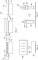
Figure 1 is a schematic diagram of a process of joining a thermoplastic skin and a thermoplastic core having similar properties according to this disclosure. -
Figure 2 is a schematic diagram of a process of joining a thermoplastic skin and a thermoplastic core having dissimilar properties according to this disclosure. -
Figure 3 is a schematic diagram of a process of joining a thermoplastic skin and a thermoplastic core having similar properties using a thermoplastic film according to this disclosure. -
Figure 4 is a schematic diagram of a process of joining a thermoplastic skin and a thermoplastic core having dissimilar properties using a thermoplastic film according to this disclosure. -
Figure 5 is a schematic diagram of a two-step process of joining a thermoplastic skin and a thermoplastic core using a thermoplastic film according to this disclosure. -
Figure 6 is a schematic diagram of another two-step process of joining a thermoplastic skin and a thermoplastic core using a thermoplastic film according to this disclosure. -
Figure 7 is a schematic diagram of yet another two-step process of joining a thermoplastic skin and a thermoplastic core using a thermoplastic film according to this disclosure. -
Figure 8 is a schematic diagram of a process of emulating reticulation in a thermoplastic core according to this disclosure. -
Figure 9 is a schematic diagram of the emulated reticulation in a thermoplastic core according to this disclosure. -
Figure 10 is an oblique view of a portion of a thermoplastic core according to this disclosure. -
Figure 11 is a schematic diagram of a helicopter according to this disclosure. -
Figure 12 is a schematic diagram of a tiltrotor according to this disclosure. -
Figure 13 is a flowchart of a method of constructing a thermoplastic component according to this disclosure. -
Figure 14 is a flowchart of another method of constructing a thermoplastic component according to this disclosure. - In this disclosure, reference may be made to the spatial relationships between various components and to the spatial orientation of various aspects of components as the devices are depicted in the attached drawings. However, as will be recognized by those skilled in the art after a complete reading of this disclosure, the devices, members, apparatuses, etc. described herein may be positioned in any desired orientation. Thus, the use of terms such as "above," "below," "upper," "lower," or other like terms to describe a spatial relationship between various components or to describe the spatial orientation of aspects of such components should be understood to describe a relative relationship between the components or a spatial orientation of aspects of such components, respectively, as the device described herein may be oriented in any desired direction.
- This invention relates generally to constructing a thermoplastic component. More specifically, this disclosure relates to constructing a thermoplastic component by adhering a fiber-reinforced thermoplastic skin to a fiber-reinforced thermoplastic core. Thermoplastics, by definition, rely on a phase-change when processed by melting and re-solidifying upon cooling. Thermoplastic materials begin in a first solid state that is melted into a second semi-liquid or liquid state, consolidated with another component, and then re-solidified when cooled to create a single "welded," "melt-bonded," and/or "fusion-bonded" thermoplastic component. As such, constructing a thermoplastic component in accordance with this disclosure requires melting a surface and/or surface element of each of thermoplastic skin and a thermoplastic core at an interface between the two, consolidating the skin and core at the interface via contact and/or an application of pressure, and then cooling the skin and core at the interface to create the single unitary thermoplastic component.
- Referring now to
Figure 1 , a schematic diagram of aprocess 100 of joining athermoplastic skin 102 and athermoplastic core 104 having similar properties is shown according to this disclosure.Thermoplastic skin 102 andthermoplastic core 104 may generally be formed from a fiber-reinforced thermoplastic material and comprise substantially similar material properties (e.g. composition, strength, melting temperature, etc.). In this embodiment,thermoplastic skin 102 andthermoplastic core 104 comprise a substantially similar melting temperature. To beginprocess 100, aheat source 106 is employed to selectively applyheat 108 to aninterface 103 of thethermoplastic skin 102 and/or aninterface 105 of thethermoplastic core 104 to cause thethermoplastic skin 102 and thethermoplastic core 104 to melt at theirrespective interfaces - In some embodiments,
heat source 106 may comprise a vibratory mechanism that selectively vibrates at least one of thethermoplastic skin 102 and thethermoplastic core 104 to generateheat 108 via friction between theinterfaces heat 108 through friction, it will be appreciated that theinterfaces heat source 106 applying the vibration. In other embodiments,heat source 106 may be configured to generateinductive heat 108,radiant heat 108, and/or any other type ofheat 108 to melt thethermoplastic skin 102 and thethermoplastic core 104 to melt at theirrespective interfaces interfaces heat 108. However, in some embodiments, theinterfaces heat 108. - When inductive, radiant, and/or other type of
heat 108 is employed, theheat 108 may be directed onto theinterfaces thermoplastic skin 102 and/or thethermoplastic core 104 until each of theinterfaces heat 108 at theinterfaces thermoplastic skin 102 and thethermoplastic core 104 maintain their structural integrity. Theheat 108 transfers sufficient energy to bring theinterfaces thermoplastic skin 102 and thethermoplastic core 104 at theirrespective interfaces interfaces interfaces thermoplastic skin 102 and thethermoplastic core 104 undergo a phase-change from a solid to liquid. In one example, theinterfaces heat 108 and begin to soften at about 360 to 380 degrees Fahrenheit. Each of theinterfaces interfaces - To reach the fully melted state of the
interfaces interfaces thermoplastic skin 102 andthermoplastic core 104 retain their shapes and structural integrity such that melting only occurs at theinterfaces thermoplastic skin 102 and thethermoplastic core 104 are consolidated by forcing thethermoplastic skin 102 and thethermoplastic core 104 into contact through gravity, pressure, and/or another external force. However, in embodiments where thethermoplastic skin 102 andthermoplastic core 104 are in contact prior to applyingheat 108, theinterfaces melted interfaces interfaces heat 108 to theinterfaces thermoplastic component 120. The thermal mass may quickly extract heat from thethermoplastic component 120, which may further retain the integrity and/or structure ofthermoplastic core 104. - Upon consolidation, the
interfaces thermoplastic component 120. Accordingly, thethermoplastic skin 102 and thethermoplastic core 104 are joined by the welding and/or fusion-bonding process that requires no adhesive. Theinterfaces thermoplastic skin 102 and thethermoplastic core 104 are simply melted, consolidated, and then cooled to form thethermoplastic component 120. By eliminating the need for adhesive to form the bond between thethermoplastic skin 102 and thethermoplastic core 104, costly and complex surface preparation procedures necessary in bonding thermoset components are eliminated. Further, the reticulation formed by thermoset components is also emulated throughprocess 100. Additionally, it will be appreciated that fiber-reinforcedthermoplastic components 120 exhibit improved damage tolerance, better strength after impact, and other structurally desirable characteristics as compared to most current thermoset components. - Referring now to
Figure 2 , a schematic diagram of aprocess 200 of joining athermoplastic skin 202 and athermoplastic core 204 having dissimilar properties is shown according to this disclosure.Process 200 may be substantially similar toprocess 100 and used to jointhermoplastic skin 202 tothermoplastic core 204 to form athermoplastic component 220 in a substantially similar manner to process 100. However,thermoplastic skin 202 comprises dissimilar properties fromthermoplastic core 204. In some embodiments,thermoplastic skin 202 comprises a fiber-reinforced thermoplastic material having a slightly lower melting temperature than thethermoplastic core 204. Accordingly, whenheat 208 is applied fromheat source 206,interface 203 of thethermoplastic skin 202 reaches its melting temperature prior tointerface 205 reaching its melting temperature. - In some embodiments,
thermoplastic skin 202 may generally be formed from a fiber-reinforced thermoplastic material that is impregnated with a constituent 207 that enhances heat transfer between theheat source 206 and thethermoplastic skin 202.Constituent 207 comprises an interspersed metallic component and/or other material component that enhances heat transfer by more readily responding to inductive, radiant, and other type ofheat 208. Accordingly, whenheat 208 is applied fromheat source 206, constituent 207 allows theinterface 203 of thethermoplastic skin 202 to reach its melting temperature prior to theinterface 205 of thethermoplastic core 204 reaching its melting temperature. The material of thethermoplastic skin 202 may be selected, designed, and/or otherwise impregnated withconstituent 207 such that theinterface 203 of thethermoplastic skin 202 reaches its melting temperature just prior to that of theinterface 205 of thethermoplastic core 204. This lowers the risk of thethermoplastic core 204 receiving toomuch heat 208, thereby protecting and preserving the structural integrity of thethermoplastic core 204 whenheat 208 is applied to join thethermoplastic skin 202 and thethermoplastic core 204. - Referring now to
Figure 3 , a schematic diagram of aprocess 300 of joining athermoplastic skin 302 and athermoplastic core 304 having similar properties using athermoplastic film 310 is shown according to this disclosure.Process 300 may be substantially similar toprocess 100 and used to jointhermoplastic skin 302 tothermoplastic core 304 to form athermoplastic component 320 in a substantially similar manner to process 100. However,process 300 utilizesthermoplastic film 310 disposed betweeninterfaces thermoplastic skin 302 andthermoplastic core 304 and configured to join thethermoplastic skin 302 and thethermoplastic core 304 to form thethermoplastic component 320. In some embodiments,thermoplastic film 310 comprises a thermoplastic material comprising a substantially similar melting temperature to that of thethermoplastic skin 302 andthermoplastic core 304. However, in some embodiments,thermoplastic film 310 comprises a thermoplastic material comprising a slightly lower melting temperature than thethermoplastic skin 302 andthermoplastic core 304. - To join the
thermoplastic skin 302 to thethermoplastic core 304,heat 308 may be directed to thethermoplastic film 310 while also directedheat 308 to theinterfaces thermoplastic film 310 may flow between the at least partially meltedinterfaces thermoplastic skin 310 may be sandwiched between thethermoplastic skin 302 and thethermoplastic core 104 by forcing thethermoplastic skin 102 and thethermoplastic core 104 into contact through gravity, pressure, and/or another external force. Upon cooling, thethermoplastic film 310 joins thethermoplastic skin 102 and thethermoplastic core 104 by the welding and/or fusion-bonding provided by thethermoplastic film 310, thereby forming thethermoplastic component 320. Similarly toprocesses 100,process 300 eliminates the need for adhesive and the costly and complex surface preparation procedures necessary in bonding thermoset components. - Referring now to
Figure 4 , a schematic diagram of aprocess 400 of joining athermoplastic skin 402 and athermoplastic core 404 having dissimilar properties using athermoplastic film 410 is shown according to this disclosure.Process 400 may be substantially similar toprocess 300 and used to jointhermoplastic skin 402 tothermoplastic core 404 to form athermoplastic component 420 in a substantially similar manner to process 300. However,thermoplastic film 410 comprises dissimilar properties fromthermoplastic skin 402 andthermoplastic core 404. In some embodiments,thermoplastic film 410 comprises a fiber-reinforced thermoplastic material, the thermoplastic portion having a lower melting temperature than thethermoplastic skin 402 andthermoplastic core 404. Accordingly, whenheat 408 is applied fromheat source 406,thermoplastic film 410 reaches its melting temperature prior tointerfaces - In some embodiments,
thermoplastic film 410 may generally be formed from a fiber-reinforced thermoplastic material that is impregnated with a constituent 407 substantially similar to constituent 207 that enhances heat transfer between theheat source 406 and thethermoplastic film 410.Constituent 407 may comprise an interspersed metallic component and/or other material component that enhances heat transfer by more readily responding to inductive, radiant, and other type ofheat 408. However, in some embodiments, constituent 407 may be configured to react to an induced electromagnetic field (EMF). Accordingly, whenheat 408 is applied fromheat source 406, constituent 407 allows thethermoplastic film 410 to reach its melting temperature prior to theinterfaces thermoplastic film 410 may therefore be selected, designed, and/or otherwise impregnated withconstituent 407 such that thethermoplastic film 410 reaches its melting temperature just prior to that of theinterfaces thermoplastic skin 402 and thethermoplastic core 404 receiving toomuch heat 408, thereby protecting and preserving the structural integrity of thethermoplastic core 404 whenheat 408 is applied to join thethermoplastic skin 202 and thethermoplastic core 404 and form thethermoplastic component 420. - Referring now to
Figure 5 , a schematic diagram of a two-step process 500 of joining athermoplastic skin 502 and athermoplastic core 504 using athermoplastic film 510 is shown according to this disclosure.Process 500 may be substantially similar toprocesses thermoplastic skin 502 tothermoplastic core 504 to form athermoplastic component 520 in a substantially similar manner toprocesses process 500 involves multiple steps to form thethermoplastic component 520. In a first step,heat 508 is applied by theheat source 506 to thethermoplastic film 510 andinterface 505 of thethermoplastic core 504, whereby thethermoplastic film 510 is joined to thethermoplastic core 504 in accordance with techniques described in this disclosure to form anintermediate thermoplastic component 519. In a second step,heat 508 is applied to thethermoplastic film 510 andinterface 503 of thethermoplastic skin 502, whereby thethermoplastic skin 502 is joined to theintermediate thermoplastic component 519 in accordance with techniques described in this disclosure to form thethermoplastic component 520. - Referring now to
Figure 6 , a schematic diagram of another two-step process 600 of joining athermoplastic skin 602 and athermoplastic core 604 using athermoplastic material 610 is shown according to this disclosure.Process 600 may be substantially similar toprocess 500 and used to jointhermoplastic skin 602 tothermoplastic core 604 to form athermoplastic component 620 in a substantially similar manner to process 500. However, in a first step ofprocess 600,thermoplastic core 604 is dipped into a melted, liquid-state thermoplastic material 610. In some embodiments,thermoplastic material 610 may be carried by avessel 611 and melted by applyingheat 608 fromheat source 606. However, in other embodiments,vessel 611 may be heated by theheat source 606 to melt thethermoplastic material 610 prior to dipping thethermoplastic core 604 into the meltedthermoplastic material 610. When thethermoplastic core 604 is dipped into the meltedthermoplastic material 610, theinterface 605 of thethermoplastic core 604 is coated with the meltedthermoplastic material 610, and when cooled, thethermoplastic core 604 and thethermoplastic material 610 formintermediate thermoplastic component 619. Thus, similarly to process 500, in a second step ofprocess 600,heat 608 is applied to thethermoplastic material 610 andinterface 603 of thethermoplastic skin 602, whereby thethermoplastic skin 602 is joined to theintermediate thermoplastic component 619 in accordance with techniques described in this disclosure to form thethermoplastic component 620. - Referring now to
Figure 7 , a schematic diagram of yet another two-step process 700 of joining athermoplastic skin 702 and athermoplastic core 704 using a thermoplastic film is shown according to this disclosure.Process 700 may be substantially similar toprocess thermoplastic skin 702 tothermoplastic core 704 to form athermoplastic component 720 in a substantially similar manner toprocesses thermoplastic film 710 is formed from a fiber-reinforced thermoplastic material that comprises constituent 707.Constituent 707 may comprise an interspersed electrically conductive and/or resistive component and be configured to conduct electrical current to induceheat 708 into thethermoplastic skin 710. When a current is applied to thethermoplastic skin 710 by theheat source 706, theconstituents 707 in the thermoplastic skin generate sufficient heat to melt thethermoplastic skin 710. - Accordingly, in a first step of
process 700, thethermoplastic skin 710 is joined to thethermoplastic core 704 to form anintermediate thermoplastic component 719. In a second step ofprocess 700, thethermoplastic skin 702 is joined to theintermediate thermoplastic component 719. However, in alternative embodiments, thethermoplastic skin 702 and thethermoplastic core 704 may be joined in a single step substantially similar toprocess 400. The material of thethermoplastic film 710 may therefore be selected, designed, and/or otherwise impregnated withconstituent 707 such that thethermoplastic film 710 reaches its melting temperature just prior to that of theinterfaces thermoplastic skin 702 and thethermoplastic core 704 receiving toomuch heat 708, thereby protecting and preserving the structural integrity of thethermoplastic core 704 whenheat 708 is applied to theinterfaces thermoplastic skin 702 and thethermoplastic core 704 and form thethermoplastic component 720. - Referring now to
Figures 8 and 9 , a schematic diagram of aprocess 800 of emulating reticulation in athermoplastic core 804 and a schematic diagram of the emulated reticulation in athermoplastic core 804 are shown, respectively, according to this disclosure.Process 800 comprises employing aheat source 806 having a flat and/or other complementary-shaped surface and raising the surface temperature above a melting temperature of thethermoplastic core 804. Theheat source 806 is selectively moved into contact with an interface 805' of thethermoplastic core 804. Pressure is then applied to thethermoplastic core 804 by theheat source 806 to heat thethermoplastic core 804 at the interface 805', thereby at least partially melting the interface 805' of thethermoplastic core 804. As pressure is applied to the melted interface 805', the edges of the interface 805' are slightly crushed, smashed, and/or otherwise deformed, while the remainder of thethermoplastic core 804 maintains its structural integrity. In some embodiments, interface 805' may be smashed about 0.5 to about 1.0 millimeters. The interface 805' may then be cooled, and pressure from theheat source 806 is relieved as theheat source 806 is removed from contact with thethermoplastic core 804, and the result of the deformation of the interface 805' is acompressed interface 805" that comprises a larger surface area as compared to the uncrushed interface 805'. As such, it will be appreciated thatcompressed interface 805" may be formed via crushing, folding, deforming, causing an accordion-like collapsing, twisting, and/or any other natural deformative process caused by the application of heat and pressure. Furthermore, it will be appreciated that increased amount of heat and/or pressure may result in an increased surface area of thecompressed interface 805", and heat and pressure may be controlled to produce acompressed interface 805" having a specific surface area across thethermoplastic core 804. - The
compressed interface 805" thereby emulates the reticulation caused by surface tension in current thermoset components that employ adhesive between a skin and core and/or aluminum crushed core components. Thus, only the interface 805' is compressed to form thecompressed interface 805", while the remainder of thethermoplastic core 804 retains its structural integrity. Further, it will be appreciated thatthermoplastic core 804 may be representative ofthermoplastic cores compressed interface 805" creates a larger footprint than other non-crushed portions of thethermoplastic core 804 for an increased surface contact area between thethermoplastic core 804 and a subsequentthermoplastic skin compressed interface 805" created byprocess 800 thus strengthens the joint between athermoplastic core thermoplastic skin optional thermoplastic film process 800 may be used prior to any ofprocesses compressed interface 805" on thethermoplastic cores - Furthermore, while
processes single thermoplastic skin thermoplastic skins thermoplastic films thermoplastic core thermoplastic skins thermoplastic films thermoplastic core thermoplastic component - Referring now to
Figure 10 , an oblique view of a portion of athermoplastic core 900 is shown according to this disclosure.Thermoplastic core 900 is generally formed from a plurality of thinthermoplastic components hollow cells 910 comprising aninterface 912 substantially similar tointerfaces process 800 to form acompressed interface 805".Thermoplastic core 900 generally comprises honeycomb-shapedcells 910. However, in other embodiments,thermoplastic core 900 may comprise any other shaped (e.g. round, rectangular, octagonal)cells 910.Thermoplastic core 900 generally comprises a large cell thermoplastic core (LCTC) that is representative ofthermoplastic cores thermoplastic components Large cells 910 afford thethermoplastic core 900 increased performance characteristics to shear energy as opposed to small cell cores.Large cells 910 inthermoplastic core 900 also allow the structural response of thethermoplastic component skins large cells 910 increase the importance of reticulation in the cell, thereby forming acompressed interface 805" oninterface 912 is imperative to optimizing performance. However, it will be appreciated that the size and shape of thethermoplastic components cells 910 may be selected based on a specific application. - Referring now to
Figure 11 , a schematic diagram of ahelicopter 1000 is shown according to this disclosure.Helicopter 1000 comprises afuselage 1002, anempennage 1004 having atail rotor 1010, and arotor system 1006 comprising a plurality ofrotor blades 1008. It will be appreciated that processes 100-800 may be used to form athermoplastic component fuselage 1002,empennage 1004,rotor blades 1008, and/ortail rotor 1010 ofhelicopter 1000. - Referring now to
Figure 12 , a schematic diagram of atiltrotor 1100 is shown according to this disclosure.Tiltrotor 1100 comprises afuselage 1102 with attachedwings 1104.Pylons 1106 are disposed at the outboard ends of thewings 1104 and are rotatable between a helicopter mode (shown) and a forward-flight airplane mode (not shown). Eachpylon 1106 comprises arotor system 1108 comprising a plurality ofrotor blades 1110. It will be appreciated that processes 100-800 may be used to form athermoplastic component fuselage 1102,wings 1104, and/orrotor blades 1110 oftiltrotor 1100. - Furthermore, in some embodiments, processes 100, 200, 300, 400, 500, 600, 700, 800 may be used to construct
components cell thermoplastic core 900 used to formthermoplastic components cell thermoplastic core 900 used to formthermoplastic components thermoplastic components rotor blades tail rotors 1010, andwings 1104, other flight control surfaces of ahelicopter 1000,tiltrotor 1110 and/or other aircraft, and/or afuselage aircraft - Referring now to
Figure 13 , a flowchart of amethod 1200 of constructing athermoplastic component Method 1200 begins atblock 1202 by providing athermoplastic skin thermoplastic core Method 1200 continues atblock 1204 by heating aninterface thermoplastic skin interface thermoplastic core Method 1200 continues atblock 1206 by applying pressure to at least one of the thermoplastic skin and the thermoplastic core to make contact between theinterfaces Method 1200 concludes atblock 1208 by cooling theinterfaces thermoplastic skin thermoplastic core thermoplastic skin thermoplastic core unitary thermoplastic component - Referring now to
Figure 14 , a flowchart of anothermethod 1300 of constructing a thermoplastic component is shown according to this disclosure.Method 1300 begins atblock 1302 by providing athermoplastic skin thermoplastic core Method 1300 continues atblock 1304 by heating thethermoplastic film interface thermoplastic core Method 1300 continues atblock 1306 by heating thethermoplastic film interface thermoplastic skin thermoplastic film interface thermoplastic core block 1306. However, in other embodiments, blocks 1304 and 1306 may be accomplished simultaneously. -
Method 1300 continues asblock 1308 by applying pressure to at least one of thethermoplastic skin thermoplastic core thermoplastic film interfaces Method 1300 concludes atblock 1310 by cooling thethermoplastic film interfaces thermoplastic skin thermoplastic film thermoplastic core thermoplastic skin thermoplastic film thermoplastic core unitary thermoplastic component - At least one embodiment is disclosed, and variations, combinations, and/or modifications of the embodiment(s) and/or features of the embodiment(s) made by a person having ordinary skill in the art are within the scope of this disclosure. Alternative embodiments that result from combining, integrating, and/or omitting features of the embodiment(s) are also within the scope of this disclosure. Where numerical ranges or limitations are expressly stated, such express ranges or limitations should be understood to include iterative ranges or limitations of like magnitude falling within the expressly stated ranges or limitations (e.g., from about 1 to about 10 includes, 2, 3, 4, etc.; greater than 0.10 includes 0.11, 0.12, 0.13, etc.). For example, whenever a numerical range with a lower limit, Rl, and an upper limit, Ru, is disclosed, any number falling within the range is specifically disclosed. In particular, the following numbers within the range are specifically disclosed: R=Rl +k * (Ru-Rl), wherein k is a variable ranging from 1 percent to 100 percent with a 1 percent increment, i.e., k is 1 percent, 2 percent, 3 percent, 4 percent, 5 percent,...50 percent, 51 percent, 52 percent,..., 95 percent, 96 percent, 95 percent, 98 percent, 99 percent, or 100 percent. Moreover, any numerical range defined by two R numbers as defined in the above is also specifically disclosed.
- Use of the term "optionally" with respect to any element of a claim means that the element is required, or alternatively, the element is not required, both alternatives being within the scope of the claim. Use of broader terms such as comprises, includes, and having should be understood to provide support for narrower terms such as consisting of, consisting essentially of, and comprised substantially of. Accordingly, the scope of protection is not limited by the description set out above but is defined by the claims that follow, that scope including all equivalents of the subject matter of the claims. Each and every claim is incorporated as further disclosure into the specification and the claims are embodiment(s) of the present invention. Also, the phrases "at least one of A, B, and C" and "A and/or B and/or C" should each be interpreted to include only A, only B, only C, or any combination of A, B, and C.
Claims (15)
- A method of constructing a thermoplastic component, comprising:providing a thermoplastic skin and a thermoplastic core;heating an interface of the thermoplastic skin and an interface of the thermoplastic core;applying pressure to at least one of the thermoplastic skin and the thermoplastic core to make contact between the interfaces;cooling the interfaces below a melting point of each of the thermoplastic skin and the thermoplastic core to consolidate the thermoplastic skin and the thermoplastic core into a unitary thermoplastic component.
- The method of claim 1, wherein the heating the interfaces is accomplished by vibrating at least one of the thermoplastic skin and a thermoplastic core to induce friction between the interfaces.
- The method of claim 1, wherein the heating the interfaces is accomplished by at least one of inductive heat and radiant heat.
- The method of claim 1 or of claim 2 or of claim 3, wherein the thermoplastic skin and a thermoplastic core comprise a substantially similar melting temperature.
- A method of constructing a thermoplastic component, comprising:providing a thermoplastic skin, a thermoplastic core, and a thermoplastic film;heating the thermoplastic film and an interface of the thermoplastic core;heating the thermoplastic film and an interface of the thermoplastic skin;applying pressure to at least one of the thermoplastic skin and the thermoplastic core to make contact between the thermoplastic film and each of the interfaces;cooling the thermoplastic film and the interfaces below the melting point of each of the thermoplastic skin, the thermoplastic film, and the thermoplastic core to consolidate the thermoplastic skin, the thermoplastic film, and the thermoplastic core into a unitary thermoplastic component.
- The method of claim 1 or of any of claims 2 to 4, wherein the thermoplastic skin is impregnated with a constituent configured to enhance heat transfer of the thermoplastic skin; or
the method of claim 5, wherein the thermoplastic film is impregnated with a constituent configured to enhance heat transfer of the thermoplastic film. - The method of claim 6 as it depends directly or indirectly from claim 1, wherein the thermoplastic skin comprises a lower melting temperature than the thermoplastic core; or
the method of claim 6 as it depends from claim 5, wherein the thermoplastic film comprises a lower melting temperature than each of the thermoplastic skin and the thermoplastic core. - The method of claim 1 or of claim 5, or of any preceding claim, further comprising: at least partially crushing the interface of the thermoplastic core with a heated apparatus to form an at least partially crushed, reticulated interface comprising an increased surface area for contact with the thermoplastic skin with respect to the remainder of the thermoplastic core.
- The method of claim 1, or of claim 5 or of any preceding claim, wherein the thermoplastic core comprises a large cell thermoplastic core (LCTC).
- The method of claim 1 or of claim 5 or of any preceding claim, wherein the thermoplastic component forms at least a portion of at least one of a fuselage, an empennage, a tail rotor, a rotor blade, and a wing of an aircraft.
- The method of claim 5 or of any preceding claim dependent directly or indirectly from claim 5, wherein the heating the thermoplastic film and an interface of the thermoplastic core occurs simultaneously with the heating the interface of the thermoplastic skin.
- The method of claim 5 or of any preceding claim dependent directly or indirectly from claim 5, further comprising: cooling the thermoplastic film and the interface of the thermoplastic core to form an intermediate thermoplastic component prior to heating the thermoplastic skin.
- The method of claim 5 or of any preceding claim dependent directly or indirectly from claim 5, wherein the heating the interface of the thermoplastic core is accomplished by dipping the interface of the thermoplastic core into a melted, liquid phase thermoplastic film.
- The method of claim 6, wherein the constituent is configured to respond to at least one of radiant heat and an electrical current.
- The method of claim 6, wherein the constituent is configured to respond to an induced electromagnetic field (EMF).
Applications Claiming Priority (1)
| Application Number | Priority Date | Filing Date | Title |
|---|---|---|---|
| US15/842,248 US20190184646A1 (en) | 2017-12-14 | 2017-12-14 | System and method of constructing a thermoplastic component |
Publications (1)
| Publication Number | Publication Date |
|---|---|
| EP3498459A1 true EP3498459A1 (en) | 2019-06-19 |
Family
ID=61187182
Family Applications (1)
| Application Number | Title | Priority Date | Filing Date |
|---|---|---|---|
| EP18155541.8A Withdrawn EP3498459A1 (en) | 2017-12-14 | 2018-02-07 | Method of constructing a thermoplastic component |
Country Status (2)
| Country | Link |
|---|---|
| US (1) | US20190184646A1 (en) |
| EP (1) | EP3498459A1 (en) |
Cited By (3)
| Publication number | Priority date | Publication date | Assignee | Title |
|---|---|---|---|---|
| CN113001127A (en) * | 2021-04-29 | 2021-06-22 | 北京航星机器制造有限公司 | Method and device for machining skin with active cooling channel |
| CN113602477A (en) * | 2021-07-26 | 2021-11-05 | 成都飞机工业(集团)有限责任公司 | Full-composite empennage structure and forming method thereof |
| EP4241967A1 (en) * | 2022-03-07 | 2023-09-13 | Rohr, Inc. | Shimming welded interface(s) between thermoplastic components |
Families Citing this family (1)
| Publication number | Priority date | Publication date | Assignee | Title |
|---|---|---|---|---|
| US20240003329A1 (en) * | 2022-07-01 | 2024-01-04 | Rohr, Inc. | Composite thermoplastic rotor blade with integral cuff |
Citations (6)
| Publication number | Priority date | Publication date | Assignee | Title |
|---|---|---|---|---|
| US5039567A (en) * | 1989-12-04 | 1991-08-13 | Supracor Systems, Inc. | Resilient panel having anisotropic flexing characteristics and method of making same |
| WO1992010362A1 (en) * | 1990-12-04 | 1992-06-25 | Hexcel Corporation | Process for the preparation of thermoplastic honeycomb sandwich structures |
| FR2739803A1 (en) * | 1995-10-12 | 1997-04-18 | Induplast Sa | Production of thermoplastic cored e.g. polypropylene honeycomb, sandwich panel |
| WO2015085309A1 (en) * | 2013-12-06 | 2015-06-11 | Continental Structural Plastics, Inc. | Open area core with chopped fiber reinforced skin |
| EP2894025A1 (en) * | 2013-12-17 | 2015-07-15 | The Boeing Company | System and method of joining components |
| US20150298388A1 (en) * | 2012-12-04 | 2015-10-22 | The Boeing Company | Joining Composite Components Using Low Temperature Thermoplastic Film Fusion |
Family Cites Families (7)
| Publication number | Priority date | Publication date | Assignee | Title |
|---|---|---|---|---|
| US3574031A (en) * | 1967-03-24 | 1971-04-06 | Heller William C Jun | Method of heat welding thermoplastic bodies using a stratum of susceptor material |
| US5316604A (en) * | 1990-12-04 | 1994-05-31 | Hexcel Corporation | Process for the preparation of thermoplastic sandwich structures |
| US20090127253A1 (en) * | 1997-06-06 | 2009-05-21 | Philip Stark | Temperature-controlled induction heating of polymeric materials |
| US6797089B2 (en) * | 2002-02-20 | 2004-09-28 | Branson Ultrasonics Corporation | Energy management system and welding process therefor |
| FR2837416B1 (en) * | 2002-03-25 | 2005-11-25 | Airbus France | ULTRASOUND BONDING PROCESS |
| EP2430251A4 (en) * | 2009-05-13 | 2016-01-27 | Hunter Douglas Ind Switzerland | Structured-core laminate panels and methods of forming the same |
| DE102014007510A1 (en) * | 2014-05-23 | 2015-11-26 | Airbus Defence and Space GmbH | Sandwich component and method for producing a sandwich component |
-
2017
- 2017-12-14 US US15/842,248 patent/US20190184646A1/en not_active Abandoned
-
2018
- 2018-02-07 EP EP18155541.8A patent/EP3498459A1/en not_active Withdrawn
Patent Citations (6)
| Publication number | Priority date | Publication date | Assignee | Title |
|---|---|---|---|---|
| US5039567A (en) * | 1989-12-04 | 1991-08-13 | Supracor Systems, Inc. | Resilient panel having anisotropic flexing characteristics and method of making same |
| WO1992010362A1 (en) * | 1990-12-04 | 1992-06-25 | Hexcel Corporation | Process for the preparation of thermoplastic honeycomb sandwich structures |
| FR2739803A1 (en) * | 1995-10-12 | 1997-04-18 | Induplast Sa | Production of thermoplastic cored e.g. polypropylene honeycomb, sandwich panel |
| US20150298388A1 (en) * | 2012-12-04 | 2015-10-22 | The Boeing Company | Joining Composite Components Using Low Temperature Thermoplastic Film Fusion |
| WO2015085309A1 (en) * | 2013-12-06 | 2015-06-11 | Continental Structural Plastics, Inc. | Open area core with chopped fiber reinforced skin |
| EP2894025A1 (en) * | 2013-12-17 | 2015-07-15 | The Boeing Company | System and method of joining components |
Cited By (4)
| Publication number | Priority date | Publication date | Assignee | Title |
|---|---|---|---|---|
| CN113001127A (en) * | 2021-04-29 | 2021-06-22 | 北京航星机器制造有限公司 | Method and device for machining skin with active cooling channel |
| CN113602477A (en) * | 2021-07-26 | 2021-11-05 | 成都飞机工业(集团)有限责任公司 | Full-composite empennage structure and forming method thereof |
| CN113602477B (en) * | 2021-07-26 | 2024-03-15 | 成都飞机工业(集团)有限责任公司 | Tail wing structure made of full composite material and forming method thereof |
| EP4241967A1 (en) * | 2022-03-07 | 2023-09-13 | Rohr, Inc. | Shimming welded interface(s) between thermoplastic components |
Also Published As
| Publication number | Publication date |
|---|---|
| US20190184646A1 (en) | 2019-06-20 |
Similar Documents
| Publication | Publication Date | Title |
|---|---|---|
| US20190184646A1 (en) | System and method of constructing a thermoplastic component | |
| Wang et al. | Progress on ultrasonic guided waves de-icing techniques in improving aviation energy efficiency | |
| US10723438B2 (en) | System and methods of constructing composite assemblies | |
| US11634208B2 (en) | Rigid-flexible coupled UAV morphing wing and additive manufacturing method thereof | |
| CA2834751C (en) | Aircraft structure for high capacity pull off | |
| EP2097314B1 (en) | Aerofoil member | |
| US20120292446A1 (en) | Vertical Laminate Noodle for High Capacity Pull-Off for a Composite Stringer | |
| US9887401B2 (en) | Battery assembly, battery containment apparatus, and related methods of manufacture | |
| US20190330848A1 (en) | Thermoplastic truss structure for use in wing and rotor blade structures and methods for manufacture | |
| Vijayanandh et al. | Material optimization of high speed micro aerial vehicle using FSI simulation | |
| CA2783109A1 (en) | Vertical laminate noodle for high capacity pull-off for a composite stringer | |
| JP7005632B2 (en) | Connection device whose separation is controlled by the thermal effect of non-pyro technique with reduced reaction time | |
| US11738493B2 (en) | Method of manufacturing an assembly fixture and a composite product | |
| US20170291406A1 (en) | Joining structural members using foam | |
| GB2533306A (en) | Sandwich Panel | |
| US2964444A (en) | Method of making a laminated metal airscrew blade | |
| Bertani et al. | Preliminary design of a fixed-wing UAV for the martian environment | |
| US20210078699A1 (en) | Insert for a blade of a rotary-wing aircraft and a blade of rotary-wing aircraft | |
| Bramlette et al. | Design, Construction, and Flight Testing of the World's Fastest Micro-Scale Quadcopter | |
| Thompson et al. | Experimental Design of a Flapping Wing Micro Air Vehicle through Biomimicry of Bumblebees | |
| CN108215440B (en) | Manufacturing method of stepped or hollow honeycomb sandwich structure | |
| Luo et al. | Smart design and optimization of a universal and low-cost double-tailed UAV | |
| Chakraborty et al. | Design and Development of a Novel Multifunction Intelligent Rover for Mars | |
| Golui et al. | Detailed Design of a Tail-Sitter | |
| US20210070433A1 (en) | Insert for a blade of a rotary-wing aircraft |
Legal Events
| Date | Code | Title | Description |
|---|---|---|---|
| STAA | Information on the status of an ep patent application or granted ep patent |
Free format text: STATUS: EXAMINATION IS IN PROGRESS |
|
| PUAI | Public reference made under article 153(3) epc to a published international application that has entered the european phase |
Free format text: ORIGINAL CODE: 0009012 |
|
| 17P | Request for examination filed |
Effective date: 20180207 |
|
| AK | Designated contracting states |
Kind code of ref document: A1 Designated state(s): AL AT BE BG CH CY CZ DE DK EE ES FI FR GB GR HR HU IE IS IT LI LT LU LV MC MK MT NL NO PL PT RO RS SE SI SK SM TR |
|
| AX | Request for extension of the european patent |
Extension state: BA ME |
|
| STAA | Information on the status of an ep patent application or granted ep patent |
Free format text: STATUS: THE APPLICATION IS DEEMED TO BE WITHDRAWN |
|
| 18D | Application deemed to be withdrawn |
Effective date: 20240903 |