EP3498344A1 - Racket frame - Google Patents
Racket frame Download PDFInfo
- Publication number
- EP3498344A1 EP3498344A1 EP18199995.4A EP18199995A EP3498344A1 EP 3498344 A1 EP3498344 A1 EP 3498344A1 EP 18199995 A EP18199995 A EP 18199995A EP 3498344 A1 EP3498344 A1 EP 3498344A1
- Authority
- EP
- European Patent Office
- Prior art keywords
- head
- racket frame
- groove
- string
- racket
- Prior art date
- Legal status (The legal status is an assumption and is not a legal conclusion. Google has not performed a legal analysis and makes no representation as to the accuracy of the status listed.)
- Granted
Links
Images




Classifications
-
- A—HUMAN NECESSITIES
- A63—SPORTS; GAMES; AMUSEMENTS
- A63B—APPARATUS FOR PHYSICAL TRAINING, GYMNASTICS, SWIMMING, CLIMBING, OR FENCING; BALL GAMES; TRAINING EQUIPMENT
- A63B49/00—Stringed rackets, e.g. for tennis
- A63B49/02—Frames
- A63B49/14—Protection devices on the frame
-
- A—HUMAN NECESSITIES
- A63—SPORTS; GAMES; AMUSEMENTS
- A63B—APPARATUS FOR PHYSICAL TRAINING, GYMNASTICS, SWIMMING, CLIMBING, OR FENCING; BALL GAMES; TRAINING EQUIPMENT
- A63B49/00—Stringed rackets, e.g. for tennis
- A63B49/02—Frames
-
- A—HUMAN NECESSITIES
- A63—SPORTS; GAMES; AMUSEMENTS
- A63B—APPARATUS FOR PHYSICAL TRAINING, GYMNASTICS, SWIMMING, CLIMBING, OR FENCING; BALL GAMES; TRAINING EQUIPMENT
- A63B49/00—Stringed rackets, e.g. for tennis
- A63B49/02—Frames
- A63B49/022—String guides on frames, e.g. grommets
-
- A—HUMAN NECESSITIES
- A63—SPORTS; GAMES; AMUSEMENTS
- A63B—APPARATUS FOR PHYSICAL TRAINING, GYMNASTICS, SWIMMING, CLIMBING, OR FENCING; BALL GAMES; TRAINING EQUIPMENT
- A63B49/00—Stringed rackets, e.g. for tennis
- A63B49/02—Frames
- A63B49/08—Frames with special construction of the handle
-
- A—HUMAN NECESSITIES
- A63—SPORTS; GAMES; AMUSEMENTS
- A63B—APPARATUS FOR PHYSICAL TRAINING, GYMNASTICS, SWIMMING, CLIMBING, OR FENCING; BALL GAMES; TRAINING EQUIPMENT
- A63B49/00—Stringed rackets, e.g. for tennis
- A63B49/02—Frames
- A63B49/10—Frames made of non-metallic materials, other than wood
-
- A—HUMAN NECESSITIES
- A63—SPORTS; GAMES; AMUSEMENTS
- A63B—APPARATUS FOR PHYSICAL TRAINING, GYMNASTICS, SWIMMING, CLIMBING, OR FENCING; BALL GAMES; TRAINING EQUIPMENT
- A63B60/00—Details or accessories of golf clubs, bats, rackets or the like
- A63B60/48—Details or accessories of golf clubs, bats, rackets or the like with corrugated cross-section
-
- A—HUMAN NECESSITIES
- A63—SPORTS; GAMES; AMUSEMENTS
- A63B—APPARATUS FOR PHYSICAL TRAINING, GYMNASTICS, SWIMMING, CLIMBING, OR FENCING; BALL GAMES; TRAINING EQUIPMENT
- A63B60/00—Details or accessories of golf clubs, bats, rackets or the like
- A63B60/52—Details or accessories of golf clubs, bats, rackets or the like with slits
-
- A—HUMAN NECESSITIES
- A63—SPORTS; GAMES; AMUSEMENTS
- A63B—APPARATUS FOR PHYSICAL TRAINING, GYMNASTICS, SWIMMING, CLIMBING, OR FENCING; BALL GAMES; TRAINING EQUIPMENT
- A63B60/00—Details or accessories of golf clubs, bats, rackets or the like
- A63B60/54—Details or accessories of golf clubs, bats, rackets or the like with means for damping vibrations
-
- A—HUMAN NECESSITIES
- A63—SPORTS; GAMES; AMUSEMENTS
- A63B—APPARATUS FOR PHYSICAL TRAINING, GYMNASTICS, SWIMMING, CLIMBING, OR FENCING; BALL GAMES; TRAINING EQUIPMENT
- A63B49/00—Stringed rackets, e.g. for tennis
- A63B49/02—Frames
- A63B2049/0201—Frames with defined head dimensions
-
- A—HUMAN NECESSITIES
- A63—SPORTS; GAMES; AMUSEMENTS
- A63B—APPARATUS FOR PHYSICAL TRAINING, GYMNASTICS, SWIMMING, CLIMBING, OR FENCING; BALL GAMES; TRAINING EQUIPMENT
- A63B2102/00—Application of clubs, bats, rackets or the like to the sporting activity ; particular sports involving the use of balls and clubs, bats, rackets, or the like
- A63B2102/02—Tennis
-
- A—HUMAN NECESSITIES
- A63—SPORTS; GAMES; AMUSEMENTS
- A63B—APPARATUS FOR PHYSICAL TRAINING, GYMNASTICS, SWIMMING, CLIMBING, OR FENCING; BALL GAMES; TRAINING EQUIPMENT
- A63B2209/00—Characteristics of used materials
- A63B2209/02—Characteristics of used materials with reinforcing fibres, e.g. carbon, polyamide fibres
-
- A—HUMAN NECESSITIES
- A63—SPORTS; GAMES; AMUSEMENTS
- A63B—APPARATUS FOR PHYSICAL TRAINING, GYMNASTICS, SWIMMING, CLIMBING, OR FENCING; BALL GAMES; TRAINING EQUIPMENT
- A63B2209/00—Characteristics of used materials
- A63B2209/02—Characteristics of used materials with reinforcing fibres, e.g. carbon, polyamide fibres
- A63B2209/023—Long, oriented fibres, e.g. wound filaments, woven fabrics, mats
Definitions
- the present invention relates to racket frames for use in tennis, etc.
- JP Patent No. 6053539 discloses a racket frame in which the compression elastic modulus of each side reinforcing layer is set so as to be lower than the compression elastic modulus of a top reinforcing layer, thereby promoting deformation of the racket frame.
- JP Patent No. 6053539 indicates that, when a player hits a ball at a portion other than the sweet spot of a racket, the shock upon hitting the ball is alleviated by deformation of the racket frame, and the ball is launched at a high speed due to restoration.
- JP Patent No. 6053539 deformation of the racket frame is positively promoted by making the compression elastic modulus of the top reinforcing layer of the racket frame and the compression elastic modulus of each side reinforcing layer different from each other.
- an object of the present invention is to provide a racket frame on which design change can be easily performed by simple processing.
- a racket frame includes a head formed in a ring shape along a face, and, on the head, a first groove in which a base portion for connecting grommets is to be inserted is formed in a radially outer region of the head so as to be recessed toward a radially inner side, and a second groove is formed in the radially outer region of the head so as to be recessed toward the radially inner side.
- the second groove is formed so as to be shallower than the first groove.
- a plurality of the second grooves are formed in a thickness direction, and the first groove is formed so as to be located between the plurality of the second grooves.
- a grip is attached to the head, and the second groove is formed on a head end portion of the head at a side opposite to a side at which the grip is attached.
- a grip is attached to the head, and the second groove is formed on both end portions of the head in a width direction orthogonal to an axial direction from the grip toward a head end portion at a side opposite to a side at which the grip is attached.
- a grip is attached to the head, and the second groove is formed on a head end portion of the head at a side opposite to a side at which the grip is attached, and on both end portions of the head in a width direction orthogonal to an axial direction from the grip toward the head end portion in the face.
- the second groove is formed over an entirety in a circumferential direction of the head.
- the second groove is formed intermittently along a circumferential direction of the head.
- Design change can be easily performed on the racket frame according to the present invention.
- the range of design of the racket frame can be expanded, and the production cost of the racket frame can be reduced.
- FIG. 1 shows a front view of the racket frame according to the embodiment of the present invention.
- FIG. 2 shows a side view of the racket frame according to the embodiment of the present invention.
- the racket frame 1 shown in FIGS. 1 and 2 includes a head 2, two throats 3, a shaft 4, and a grip 5. Grommets, a grip tape, an end cap, etc., are attached to the racket frame 1, and a string (gut) is stretched on the racket frame 1, whereby a racket for regulation-ball tennis is obtained.
- the up-down direction is the axial direction of the racket frame 1
- the right-left direction is the width direction of the racket frame 1.
- the right-left direction is the thickness direction of the racket frame 1.
- the racket frame 1 is formed from a fiber reinforced resin.
- the matrix resin of the fiber reinforced resin is a thermosetting resin.
- the thermosetting resin is typically an epoxy resin.
- the fibers of the fiber reinforced resin are typically carbon fibers.
- the fibers are long fibers.
- the racket frame 1 is shaped by winding a plurality of prepregs and curing the thermosetting resin included in the prepregs.
- the head 2 forms the contour of a face S1.
- the face S1 is a surface on which the string is stretched. By hitting a ball on the string stretched on the face S1 to rebound the ball, the ball is launched.
- the front shape of the head 2 is substantially an ellipse. Therefore, the head 2 is formed in a ring shape along the face S1.
- the major axis direction of the ellipse coincides with the axial direction of the racket frame 1.
- the minor axis direction of the ellipse coincides with the width direction of the racket frame 1.
- One end of each throat 3 is connected to the head 2.
- Each throat 3 is connected at the vicinity of the other end thereof to the other throat 3.
- the throats 3 extend from the head 2 to the shaft 4.
- the shaft 4 extends from the location where the two throats 3 are connected to each other.
- the shaft 4 is formed so as to be integrally connected to the throats 3.
- the grip 5 is formed so as to be integrally connected to the shaft 4.
- a portion of the head 2 that is located between the two throats 3 is a yoke 6.
- FIG. 3A is a cross-sectional view showing a cross-section taken along an IIIA-IIIA line in FIG. 2
- FIG. 3B shows an enlarged cross-sectional view of a portion A in the racket frame 1 in FIG. 3A
- the left side is the outer side of the head 2
- the right side is the inner side of the head 2.
- the racket frame 1 is formed so as to be hollow. At the position shown in FIGS. 3A and 3B in the racket frame 1, no grommet and no string are provided.
- a gut groove (first groove) 20 is formed on the head 2.
- the gut groove 20 is formed in a radially outer region of the head 2 so as to be recessed toward the radially inner side.
- the gut groove 20 is formed on the outer surface of the head 2 along the circumferential direction of the head 2.
- a plurality of grommets and a base portion for connecting the grommets are inserted into the gut groove 20.
- the gut groove 20 extends along the circumferential direction of the head 2.
- the gut groove 20 is formed over the entire circumference in the circumferential direction of the head 2.
- a deformation promotion groove (second groove) 21 for promoting deformation of the head 2 is formed on the head 2.
- the deformation promotion groove 21 is formed in the radially outer region of the head 2 so as to be recessed toward the radially inner side.
- the deformation promotion groove 21 is formed on the outer surface of the head 2 along the circumferential direction of the head 2.
- at least one deformation promotion groove 21 is formed at each of both sides of the gut groove 20 in the thickness direction such that the gut groove 20 is located therebetween.
- two deformation promotion grooves 21 are formed in the thickness direction of the racket frame 1, and the gut groove 20 is formed at a position between the two deformation promotion grooves 21 along the thickness direction in the racket frame 1.
- a width 11 shown in FIG. 3B is 1.0 mm, and a depth 12 shown in FIG. 3B is 0.5 mm.
- the width 11 shown in FIG. 3B is 0.5 mm to 1.5 mm, and the depth 12 shown in FIG. 3B is 0.3 mm to 1.0 mm.
- a plurality of deformation promotion grooves 21 are formed in the thickness direction.
- the gut groove 20 is formed so as to be located between the plurality of deformation promotion grooves 21 formed in the thickness direction.
- the deformation promotion grooves 21 are formed so as to be shallower than the gut groove 20.
- FIGS. 4A and 4B each show an enlarged cross-sectional view of the racket frame 1, taken along an IVA-IVA line in FIG. 2 .
- FIGS. 4A and 4B each show a cross-sectional view of a portion of the racket frame 1 in which a string 24 is to be passed.
- FIG. 4A shows a cross-sectional view of the racket frame 1 in a state where no grommet and no string are attached.
- a passage 22 for disposing the grommet 23 is formed in the head 2 so as to penetrate the head 2.
- FIG. 4B shows a cross-sectional view of the racket frame 1 in a state where the grommet 23 and the string 24 are attached.
- the grommet 23 is configured to have a pipe 25 and a part, in the circumferential direction, of a base portion 27.
- the pipe 25 is disposed within the passage 22, which is formed so as to penetrate the head 2. In a state where the grommet 23 and the string 24 are provided to the head 2, the pipe 25 is disposed inside the passage 22. The string 24 is disposed so as to extend through the interior of the pipe 25 toward the radially inner side of the face S1.
- the base portion 27 is disposed outside the head 2 so as to connect a plurality of grommets 23 disposed along the circumferential direction.
- the base portion 27 has a band shape and is disposed within the gut groove 20 along the circumferential direction so as to be in contact with a bottom surface 26 of the gut groove 20.
- a plurality of strings 24 are disposed along the circumferential direction of the face S1 in the head 2.
- the strings 24 are attached at the respective positions thereof along the circumferential direction so as to extend toward the inner side such that the face S1 is formed.
- the plurality of grommets 23 are disposed along the circumferential direction of the face S1 in the head 2 in corresponding relation to the respective strings 24 extending toward the inner side.
- the string 24 is disposed so as to extend along the circumferential direction at a position on the radially outer side of the base portion 27 within the gut groove 20.
- the base portion 27 for connecting the plurality of grommets 23 disposed along the circumferential direction is disposed on the side surface of the head 2 at the radially outer side, the base portion 27 is located at a position on the radially outer side of the face S1.
- the base portion 27 connects the plurality of grommets arranged along the circumferential direction of the face S1 in the head 2.
- FIG. 5 shows a cross-sectional view of the head 2 when a tennis ball is hit by the face S1 of the racket frame 1.
- the string 24 is pulled, at the time of impact, rearward in the direction in which the racket frame 1 is swung. Therefore, the string 24 is pulled, at the hitting spot, rearward in the thickness direction of the racket frame 1. Accordingly, in the vicinity of the position at which the string 24 is attached to the racket frame 1, the string 24 is pulled in the direction toward the inner side in the face S1.
- tensile force F1 shown in FIG. 5 is applied to the string 24.
- the string 24 When a tennis ball is hit at or near the sweet spot in the face S1, the string 24 is sufficiently stretched in the direction toward the inner side by the tensile force F1 toward the inner side. By the stretching of the string 24, the shock applied to the racket frame 1 is absorbed. In addition, after the stretching, the string 24 becomes restored. By the restoring force at the time of restoration, the tennis ball is launched at a high speed from the racket frame 1.
- the deformation promotion grooves 21 are formed on the head 2 of the racket frame 1 and at both sides of the gut groove 20 such that the gut groove 20 is located therebetween. Since the deformation promotion grooves 21 are formed on the head 2, the head 2 has a shape that allows the head 2 to easily deform by the tensile force F1 when the tensile force F1 is applied to the string 24.
- the head 2 is deformed, and is restored from the deformation so as to make up for a deficiency in stretching of the string 24.
- the tennis ball is launched at a high speed from the racket frame 1.
- the racket frame 1 deformation of the head 2 can make up for insufficient stretching of the string 24 when a tennis ball is hit at a position away from the sweet spot.
- the racket frame 1 has excellent shock absorption, operability, and resilience when a tennis ball is hit at a position away from the sweet spot.
- shock applied to the racket frame 1 at the time when the tennis ball collides against the face S1 is alleviated, and the resilience is maintained to be high.
- the sweet area of the racket frame 1 can be widened.
- the racket frame 1 has excellent shock absorption, operability, and resilience when a tennis ball is hit.
- the deformation promotion groove 21 may be formed at any position. Specifically, the deformation promotion groove 21 may be formed at any position on the head 2 as long as the deformation promotion groove 21 is formed at a position different from that of the gut groove 20 and can promote deformation of the head 2.
- the deformation promotion groove 21 may be formed in a region including a top position in the up-down direction of the racket frame 1. That is, the deformation promotion groove 21 may be formed in a certain region around the top position.
- a top position (head end portion) of the head 2 an end portion of the head 2 at the side opposite to the side at which the throats 3, the shaft 4, and the grip 5 are provided in the racket frame 1 is referred to as a top position (head end portion) of the head 2.
- the deformation promotion groove 21 may be formed in regions including both end portions of the head 2 in the width direction orthogonal to the axial direction of the racket frame 1 from the grip 5 toward the top position. That is, the deformation promotion groove 21 may be formed in certain regions around both end portions in the width direction of the racket frame 1.
- the deformation promotion groove 21 may be formed in both the region including the top position and the regions including both end portions in the width direction, on the head 2. That is, the deformation promotion groove 21 may be formed in both a certain region around the top position of the racket frame 1 and certain regions around both end portions in the width direction of the racket frame 1.
- the deformation promotion groove 21 may be formed over the entirety in the circumferential direction on the head 2.
- the deformation promotion groove 21 may be formed continuously on the outer surface along the circumferential direction of the head 2 over the entirety in the circumferential direction.
- the deformation promotion groove 21 may be formed intermittently along the circumferential direction of the head 2.
- the string 24 has strings used as longitudinal strings and strings used as lateral strings.
- the front shape of the head 2 is substantially an ellipse, and the major axis direction of the ellipse coincides with the axial direction of the racket frame 1. Therefore, the length of the average longitudinal string is larger than the length of the average lateral string. In general, the longitudinal strings stretch more easily than the lateral strings.
- the deformation promotion groove 21 may be provided only around the portions to which the lateral strings are attached. Accordingly, only the regions of the head 2 around the portions to which the lateral strings are attached can be easily deformed. Therefore, the insufficient degree of stretching of the lateral strings can be made up for.
- a depth difference may be produced between the deformation promotion groove 21 formed around the portions to which the lateral strings are attached and the deformation promotion groove 21 formed around the portions to which the longitudinal strings are attached. That is, the depth of the deformation promotion groove 21 formed around the portions to which the lateral strings are attached may be set so as to be larger than the depth of the deformation promotion groove 21 formed around the portions to which the longitudinal strings are attached. Accordingly, in the head 2, the regions around the portions to which the lateral strings are attached can be more easily deformed than the regions around the portions to which the longitudinal strings are attached. Thus, a deficiency in the degree of stretching of the lateral strings around the portions to which the lateral strings are attached can be made up for.
- the depth of one deformation promotion groove 21 does not have to be uniform.
- the width of one deformation promotion groove 21 does not have to be uniform.
- the deformation promotion groove 21 does not have to have a straight shape and may have a line shape such a wavy line shape or a zigzag shape.
- the racket frame which is configured such that the two deformation promotion grooves 21 are formed in the thickness direction and the gut groove 20 is located between the deformation promotion grooves 21, has been described.
- the present invention is not limited to the above embodiment.
- the deformation promotion groove 21 may be formed only at either side of the gut groove 20, that is, only one deformation promotion groove 21 may be formed in the thickness direction of the racket frame 1.
- three or more deformation promotion grooves 21 may be formed in the thickness direction.
- the number of deformation promotion grooves 21 formed in the thickness direction may be any number as long as deformation of the head 2 is promoted as a result of formation of the deformation promotion grooves 21 and thus a deficiency in the degree of stretching of the strings can be made up for.
- the deformation promotion groove 21 may be formed at the stage when the racket frame 1 is shaped by winding a plurality of prepregs and curing a thermosetting resin, or may be formed by chipping away the surface of the racket frame later.
- the deformation promotion groove 21 is formed on the head 2, and a deficiency in stretching of the string 24 can be made up for by deformation of the head 2.
- the deformation promotion groove 21 can be formed by simple processing after the racket frame 1 is produced. Therefore, the deformation promotion groove 21 can be easily formed in the racket frame 1. That is, design change of the racket frame 1 can be easily performed by merely forming the deformation promotion groove 21 without changing the material for forming the racket frame, etc. Therefore, in the case where the resilience coefficient obtained when a ball is hit at a position deviated from the center position is insufficient, design change for making up for the insufficient resilience coefficient can be easily performed on the racket frame 1.
- the racket frame shown in FIGS. 1 to 5 was produced.
- deformation promotion grooves are formed at positions at which strings as lateral strings are attached.
- a racket frame of Comparative Example 1 is similar to the racket frame of Example 1, but no deformation promotion groove is formed therein.
- Example 1 The racket frames of Example 1 and Comparative Example 1 were used, tennis balls were launched toward various positions in the faces of the respective racket frames, and resilience coefficients provided when the tennis balls were rebounded on the faces were measured.
- the conditions for launching the tennis balls toward the racket frames are as follows.
- Example 1 As for tennis rackets, two types, that is, a type in which deformation promotion grooves are formed on the outer surfaces of portions of a racket frame to which lateral strings are attached (Example 1) and a type in which no deformation promotion groove is formed in a racket frame (Comparative Example 1), were used.
- Tennis balls were launched to various hitting spots on the two types of tennis rackets, and resilience coefficients were measured for the respective hitting spots.
- Table 1 shows the results of calculation of resilience coefficients for the respective hitting spots with the distance from the top position of the racket changed.
- resilience coefficients are calculated for each of the tennis racket of Example 1 and the tennis racket of Comparative Example 1.
- resilience coefficients are calculated for the center, a position deviated outward from the center by 3 cm, and a position deviated outward from the center by 6 cm.
- Table 2 shows averages calculated for the respective positions in the width direction of the rackets.
- Table 2 Without groove (Comparative Example 1) With grooves (Example 1) Position in width direction of racket Center 0.384 0.374 3 cm from center 0.306 0.299 6 cm from center 0.149 0.166
- the resilience coefficient of the type of tennis racket of Example 1 having the deformation promotion grooves is higher than that of the type of tennis racket of Comparative Example 1 having no deformation promotion groove.
- the resilience coefficient of the tennis racket of Example 1 is higher than that of the tennis racket of Comparative Example 1 by 12%. From this result, the resilience when a tennis ball is hit at a position deviated from the center is increased by forming the deformation promotion grooves.
- a sweet area 30 of the racket frame can be widened by forming the deformation promotion grooves.
- the deformation promotion grooves are formed in regions G1 and G2 surrounded by broken lines, that is, at the positions at which strings as lateral strings are attached, the sweet area 30 is expanded in the lateral direction of the racket frame.
Landscapes
- Health & Medical Sciences (AREA)
- General Health & Medical Sciences (AREA)
- Physical Education & Sports Medicine (AREA)
- Chemical & Material Sciences (AREA)
- Engineering & Computer Science (AREA)
- Materials Engineering (AREA)
- Golf Clubs (AREA)
- Moulding By Coating Moulds (AREA)
Abstract
Description
- The present invention relates to racket frames for use in tennis, etc.
- Hitherto, a type of a racket frame of which deformation is promoted when a player hits a ball on the face of a racket has been proposed as a racket frame for use in tennis, etc. As such a racket frame, there is one disclosed in
JP Patent No. 6053539 -
JP Patent No. 6053539 JP Patent No. 6053539 - In
JP Patent No. 6053539 - However, in the racket frame disclosed in
JP No. Patent 6053539 - Therefore, in view of the above-described circumstances, an object of the present invention is to provide a racket frame on which design change can be easily performed by simple processing.
- A racket frame according to the present invention includes a head formed in a ring shape along a face, and, on the head, a first groove in which a base portion for connecting grommets is to be inserted is formed in a radially outer region of the head so as to be recessed toward a radially inner side, and a second groove is formed in the radially outer region of the head so as to be recessed toward the radially inner side.
- Preferably, the second groove is formed so as to be shallower than the first groove.
- In addition, a plurality of the second grooves are formed in a thickness direction, and the first groove is formed so as to be located between the plurality of the second grooves.
- Preferably, a grip is attached to the head, and the second groove is formed on a head end portion of the head at a side opposite to a side at which the grip is attached.
- According to another aspect of the present invention, in the racket frame, a grip is attached to the head, and the second groove is formed on both end portions of the head in a width direction orthogonal to an axial direction from the grip toward a head end portion at a side opposite to a side at which the grip is attached.
- According to still another aspect of the present invention, in the racket frame, a grip is attached to the head, and the second groove is formed on a head end portion of the head at a side opposite to a side at which the grip is attached, and on both end portions of the head in a width direction orthogonal to an axial direction from the grip toward the head end portion in the face.
- According to still another aspect of the present invention, in the racket frame, the second groove is formed over an entirety in a circumferential direction of the head.
- According to still another aspect of the present invention, in the racket frame, the second groove is formed intermittently along a circumferential direction of the head.
- Design change can be easily performed on the racket frame according to the present invention. Thus, the range of design of the racket frame can be expanded, and the production cost of the racket frame can be reduced.
-
-
FIG. 1 is a front view of a racket frame according to an embodiment of the present invention; -
FIG. 2 is a side view of the racket frame inFIG. 1 ; -
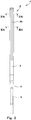
FIG. 3A is a cross-sectional view of the racket frame inFIG. 2 , taken along an IIIA-IIIA line; -
FIG. 3B is an enlarged cross-sectional view of a portion A inFIG. 3A ; -
FIG. 4A is a cross-sectional view of a portion of the racket frame inFIG. 1 , in which a string is to be passed, in a state where no grommet and no string are attached; -
FIG. 4B is a cross-sectional view in a state where a grommet and a string are attached to a head portion inFIG. 4A ; -
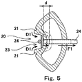
FIG. 5 is a cross-sectional view of the racket frame inFIG. 4B when the racket frame is deformed by the string being pulled toward the inner side; and -
FIG. 6 is a configuration diagram showing a sweet spot expanded by forming deformation promotion grooves in a racket frame according to Example 1 of the present invention. - The following will describe a racket frame according to an embodiment of the present invention with reference to the accompanying drawings.
-
FIG. 1 shows a front view of the racket frame according to the embodiment of the present invention. In addition,FIG. 2 shows a side view of the racket frame according to the embodiment of the present invention. - The
racket frame 1 shown inFIGS. 1 and2 includes ahead 2, twothroats 3, ashaft 4, and agrip 5. Grommets, a grip tape, an end cap, etc., are attached to theracket frame 1, and a string (gut) is stretched on theracket frame 1, whereby a racket for regulation-ball tennis is obtained. InFIG. 1 , the up-down direction is the axial direction of theracket frame 1, and the right-left direction is the width direction of theracket frame 1. InFIG. 2 , the right-left direction is the thickness direction of theracket frame 1. - The
racket frame 1 is formed from a fiber reinforced resin. The matrix resin of the fiber reinforced resin is a thermosetting resin. The thermosetting resin is typically an epoxy resin. The fibers of the fiber reinforced resin are typically carbon fibers. The fibers are long fibers. Theracket frame 1 is shaped by winding a plurality of prepregs and curing the thermosetting resin included in the prepregs. - The
head 2 forms the contour of a face S1. The face S1 is a surface on which the string is stretched. By hitting a ball on the string stretched on the face S1 to rebound the ball, the ball is launched. The front shape of thehead 2 is substantially an ellipse. Therefore, thehead 2 is formed in a ring shape along the face S1. The major axis direction of the ellipse coincides with the axial direction of theracket frame 1. The minor axis direction of the ellipse coincides with the width direction of theracket frame 1. One end of eachthroat 3 is connected to thehead 2. Eachthroat 3 is connected at the vicinity of the other end thereof to theother throat 3. Thethroats 3 extend from thehead 2 to theshaft 4. Theshaft 4 extends from the location where the twothroats 3 are connected to each other. Theshaft 4 is formed so as to be integrally connected to thethroats 3. Thegrip 5 is formed so as to be integrally connected to theshaft 4. A portion of thehead 2 that is located between the twothroats 3 is ayoke 6. -
FIG. 3A is a cross-sectional view showing a cross-section taken along an IIIA-IIIA line inFIG. 2 , andFIG. 3B shows an enlarged cross-sectional view of a portion A in theracket frame 1 inFIG. 3A . InFIG. 3B , the left side is the outer side of thehead 2, and the right side is the inner side of thehead 2. As shown inFIG. 3B , theracket frame 1 is formed so as to be hollow. At the position shown inFIGS. 3A and 3B in theracket frame 1, no grommet and no string are provided. - As shown in
FIGS. 3A and 3B , a gut groove (first groove) 20 is formed on thehead 2. Thegut groove 20 is formed in a radially outer region of thehead 2 so as to be recessed toward the radially inner side. In the present embodiment, thegut groove 20 is formed on the outer surface of thehead 2 along the circumferential direction of thehead 2. As described later, a plurality of grommets and a base portion for connecting the grommets are inserted into thegut groove 20. As shown inFIG. 2 , thegut groove 20 extends along the circumferential direction of thehead 2. In the present embodiment, thegut groove 20 is formed over the entire circumference in the circumferential direction of thehead 2. - As shown in
FIG. 3B , in addition to thegut groove 20, a deformation promotion groove (second groove) 21 for promoting deformation of thehead 2 is formed on thehead 2. Thedeformation promotion groove 21 is formed in the radially outer region of thehead 2 so as to be recessed toward the radially inner side. Thedeformation promotion groove 21 is formed on the outer surface of thehead 2 along the circumferential direction of thehead 2. In addition, at least onedeformation promotion groove 21 is formed at each of both sides of thegut groove 20 in the thickness direction such that thegut groove 20 is located therebetween. In the present embodiment, twodeformation promotion grooves 21 are formed in the thickness direction of theracket frame 1, and thegut groove 20 is formed at a position between the twodeformation promotion grooves 21 along the thickness direction in theracket frame 1. - As for optimum dimensions of each
deformation promotion groove 21, a width 11 shown inFIG. 3B is 1.0 mm, and adepth 12 shown inFIG. 3B is 0.5 mm. - In addition, as for conceivable ranges for the dimensions of the
deformation promotion grooves 21, the width 11 shown inFIG. 3B is 0.5 mm to 1.5 mm, and thedepth 12 shown inFIG. 3B is 0.3 mm to 1.0 mm. - As described above, in the present embodiment, a plurality of
deformation promotion grooves 21 are formed in the thickness direction. Thegut groove 20 is formed so as to be located between the plurality ofdeformation promotion grooves 21 formed in the thickness direction. Moreover, thedeformation promotion grooves 21 are formed so as to be shallower than thegut groove 20. -
FIGS. 4A and 4B each show an enlarged cross-sectional view of theracket frame 1, taken along an IVA-IVA line inFIG. 2 . -
FIGS. 4A and 4B each show a cross-sectional view of a portion of theracket frame 1 in which astring 24 is to be passed.FIG. 4A shows a cross-sectional view of theracket frame 1 in a state where no grommet and no string are attached. - As shown in
FIG. 4A , at the position at which agrommet 23 is to be attached, apassage 22 for disposing thegrommet 23 is formed in thehead 2 so as to penetrate thehead 2. -
FIG. 4B shows a cross-sectional view of theracket frame 1 in a state where thegrommet 23 and thestring 24 are attached. As shown inFIG. 4B , thegrommet 23 is configured to have apipe 25 and a part, in the circumferential direction, of abase portion 27. - The
pipe 25 is disposed within thepassage 22, which is formed so as to penetrate thehead 2. In a state where thegrommet 23 and thestring 24 are provided to thehead 2, thepipe 25 is disposed inside thepassage 22. Thestring 24 is disposed so as to extend through the interior of thepipe 25 toward the radially inner side of the face S1. - The
base portion 27 is disposed outside thehead 2 so as to connect a plurality ofgrommets 23 disposed along the circumferential direction. Thebase portion 27 has a band shape and is disposed within thegut groove 20 along the circumferential direction so as to be in contact with abottom surface 26 of thegut groove 20. - A plurality of
strings 24 are disposed along the circumferential direction of the face S1 in thehead 2. Thestrings 24 are attached at the respective positions thereof along the circumferential direction so as to extend toward the inner side such that the face S1 is formed. The plurality ofgrommets 23 are disposed along the circumferential direction of the face S1 in thehead 2 in corresponding relation to therespective strings 24 extending toward the inner side. - Moreover, the
string 24 is disposed so as to extend along the circumferential direction at a position on the radially outer side of thebase portion 27 within thegut groove 20. Thestring 24 extending inward, at the position at which thegrommet 23 is attached, such that the face S1 is formed, is disposed so as to extend along the circumferential direction at the position on the outer side of thebase portion 27 and further extend toward the inner side at the position of thenext grommet 23. Therefore, thestring 24 has: a portion disposed so as to extend toward the inner side such that the face S1 is formed; and a portion disposed along the circumferential direction at the outer side of thebase portion 27. - Since the
base portion 27 for connecting the plurality ofgrommets 23 disposed along the circumferential direction is disposed on the side surface of thehead 2 at the radially outer side, thebase portion 27 is located at a position on the radially outer side of the face S1. Thus, thebase portion 27 connects the plurality of grommets arranged along the circumferential direction of the face S1 in thehead 2. - When a tennis ball is hit by a tennis racket in which the
racket frame 1 is used, the tennis ball is rebounded on the face S1, whereby the tennis ball is launched. At this time, thestring 24 is bent, whereby thestring 24 is pulled toward the inner side. Thus, tensile force toward the inner side is applied to thestring 24. -
FIG. 5 shows a cross-sectional view of thehead 2 when a tennis ball is hit by the face S1 of theracket frame 1. When the tennis ball is hit by the face S1 of theracket frame 1, thestring 24 is pulled, at the time of impact, rearward in the direction in which theracket frame 1 is swung. Therefore, thestring 24 is pulled, at the hitting spot, rearward in the thickness direction of theracket frame 1. Accordingly, in the vicinity of the position at which thestring 24 is attached to theracket frame 1, thestring 24 is pulled in the direction toward the inner side in the face S1. Thus, tensile force F1 shown inFIG. 5 is applied to thestring 24. - When a tennis ball is hit at or near the sweet spot in the face S1, the
string 24 is sufficiently stretched in the direction toward the inner side by the tensile force F1 toward the inner side. By the stretching of thestring 24, the shock applied to theracket frame 1 is absorbed. In addition, after the stretching, thestring 24 becomes restored. By the restoring force at the time of restoration, the tennis ball is launched at a high speed from theracket frame 1. - On the other hand, when a tennis ball is hit at a position away from the sweet spot, there is a possibility that stretching of the
string 24 is not sufficient. When a tennis ball is hit at a position, in the face S1, which is away from the sweet spot and close to theracket frame 1, the distance from the hitting spot to the position at which thestring 24 is attached to theracket frame 1 is short. Therefore, even when thestring 24 is pulled toward the inner side due to the hit and the tensile force F1 is applied to thestring 24, the length for stretching of thestring 24 is not sufficient, and thus there is a possibility that the stretching of thestring 24 is not sufficient. Therefore, when a tennis ball is hit at a position away from the sweet spot, stretching of thestring 24 is insufficient, and thus there is a possibility that the tennis ball is insufficiently rebounded. - In the present embodiment, in addition to the
gut groove 20, thedeformation promotion grooves 21 are formed on thehead 2 of theracket frame 1 and at both sides of thegut groove 20 such that thegut groove 20 is located therebetween. Since thedeformation promotion grooves 21 are formed on thehead 2, thehead 2 has a shape that allows thehead 2 to easily deform by the tensile force F1 when the tensile force F1 is applied to thestring 24. - When the tensile force F1 is applied to the
string 24, regions closer to thegut groove 20 than to thedeformation promotion grooves 21 are deformed in directions indicated by arrow D1 as shown inFIG. 5 . Accordingly, thehead 2 is deformed into a shape shown by broken lines inFIG. 5 . At this time, stress due to the tensile force F1 is concentrated on thedeformation promotion grooves 21, and thus thehead 2 is relatively easily deformed. Since thehead 2 is deformed as shown by the broken lines inFIG. 5 , the position of thegrommet 23 at which thestring 24 is attached to thehead 2 is shifted inward by a distance d shown inFIG. 5 . - Since the
head 2 is deformed as described above, even when stretching of thestring 24 is insufficient, deformation of thehead 2 can make up for the insufficient stretching of thestring 24. Since a deficiency in stretching of thestring 24 is made up for by deformation of thehead 2, when shock is applied to theracket frame 1, thestring 24 is sufficiently displaced. The shock at the time when a tennis ball collides against the face S1 is absorbed by displacement of thestring 24, so that shock applied to theracket frame 1 is alleviated. The player can completely swing the racket while maintaining the direction of the ball-hitting face. - Even when restoration of the
string 24 is insufficient, thehead 2 is deformed, and is restored from the deformation so as to make up for a deficiency in stretching of thestring 24. By the restoring force applied supplementally by the restoration of thehead 2, the tennis ball is launched at a high speed from theracket frame 1. - In the
racket frame 1, deformation of thehead 2 can make up for insufficient stretching of thestring 24 when a tennis ball is hit at a position away from the sweet spot. As described above, theracket frame 1 has excellent shock absorption, operability, and resilience when a tennis ball is hit at a position away from the sweet spot. In addition, even when a tennis ball is hit at a position away from the sweet spot, shock applied to theracket frame 1 at the time when the tennis ball collides against the face S1 is alleviated, and the resilience is maintained to be high. Thus, as a result, the sweet area of theracket frame 1 can be widened. - As described above, when a tennis ball is hit at or near the sweet spot, the
string 24 sufficiently stretches. Therefore, only by the stretching of thestring 24, shock applied to theracket frame 1 at the time when the tennis ball collides against the face S1 is alleviated, and the resilience can be maintained high. Thus, in this case as well, theracket frame 1 has excellent shock absorption, operability, and resilience when a tennis ball is hit. - The
deformation promotion groove 21 may be formed at any position. Specifically, thedeformation promotion groove 21 may be formed at any position on thehead 2 as long as thedeformation promotion groove 21 is formed at a position different from that of thegut groove 20 and can promote deformation of thehead 2. - For example, the
deformation promotion groove 21 may be formed in a region including a top position in the up-down direction of theracket frame 1. That is, thedeformation promotion groove 21 may be formed in a certain region around the top position. Here, an end portion of thehead 2 at the side opposite to the side at which thethroats 3, theshaft 4, and thegrip 5 are provided in theracket frame 1 is referred to as a top position (head end portion) of thehead 2. - For example, the
deformation promotion groove 21 may be formed in regions including both end portions of thehead 2 in the width direction orthogonal to the axial direction of theracket frame 1 from thegrip 5 toward the top position. That is, thedeformation promotion groove 21 may be formed in certain regions around both end portions in the width direction of theracket frame 1. - For example, the
deformation promotion groove 21 may be formed in both the region including the top position and the regions including both end portions in the width direction, on thehead 2. That is, thedeformation promotion groove 21 may be formed in both a certain region around the top position of theracket frame 1 and certain regions around both end portions in the width direction of theracket frame 1. - For example, the
deformation promotion groove 21 may be formed over the entirety in the circumferential direction on thehead 2. Thedeformation promotion groove 21 may be formed continuously on the outer surface along the circumferential direction of thehead 2 over the entirety in the circumferential direction. - For example, the
deformation promotion groove 21 may be formed intermittently along the circumferential direction of thehead 2. - The
string 24 has strings used as longitudinal strings and strings used as lateral strings. As described above, the front shape of thehead 2 is substantially an ellipse, and the major axis direction of the ellipse coincides with the axial direction of theracket frame 1. Therefore, the length of the average longitudinal string is larger than the length of the average lateral string. In general, the longitudinal strings stretch more easily than the lateral strings. - In order to make up for a deficiency in the degree of stretching of the lateral strings, the
deformation promotion groove 21 may be provided only around the portions to which the lateral strings are attached. Accordingly, only the regions of thehead 2 around the portions to which the lateral strings are attached can be easily deformed. Therefore, the insufficient degree of stretching of the lateral strings can be made up for. - In order to make up for a deficiency in the degree of stretching of the lateral strings, a depth difference may be produced between the
deformation promotion groove 21 formed around the portions to which the lateral strings are attached and thedeformation promotion groove 21 formed around the portions to which the longitudinal strings are attached. That is, the depth of thedeformation promotion groove 21 formed around the portions to which the lateral strings are attached may be set so as to be larger than the depth of thedeformation promotion groove 21 formed around the portions to which the longitudinal strings are attached. Accordingly, in thehead 2, the regions around the portions to which the lateral strings are attached can be more easily deformed than the regions around the portions to which the longitudinal strings are attached. Thus, a deficiency in the degree of stretching of the lateral strings around the portions to which the lateral strings are attached can be made up for. - The depth of one
deformation promotion groove 21 does not have to be uniform. - The width of one
deformation promotion groove 21 does not have to be uniform. - The
deformation promotion groove 21 does not have to have a straight shape and may have a line shape such a wavy line shape or a zigzag shape. - In the above embodiment, the racket frame which is configured such that the two
deformation promotion grooves 21 are formed in the thickness direction and thegut groove 20 is located between thedeformation promotion grooves 21, has been described. The present invention is not limited to the above embodiment. Thedeformation promotion groove 21 may be formed only at either side of thegut groove 20, that is, only onedeformation promotion groove 21 may be formed in the thickness direction of theracket frame 1. Moreover, three or moredeformation promotion grooves 21 may be formed in the thickness direction. The number ofdeformation promotion grooves 21 formed in the thickness direction may be any number as long as deformation of thehead 2 is promoted as a result of formation of thedeformation promotion grooves 21 and thus a deficiency in the degree of stretching of the strings can be made up for. - The
deformation promotion groove 21 may be formed at the stage when theracket frame 1 is shaped by winding a plurality of prepregs and curing a thermosetting resin, or may be formed by chipping away the surface of the racket frame later. - According to the present embodiment, in the case where the degree of stretching of the
string 24 is insufficient, thedeformation promotion groove 21 is formed on thehead 2, and a deficiency in stretching of thestring 24 can be made up for by deformation of thehead 2. Thedeformation promotion groove 21 can be formed by simple processing after theracket frame 1 is produced. Therefore, thedeformation promotion groove 21 can be easily formed in theracket frame 1. That is, design change of theracket frame 1 can be easily performed by merely forming thedeformation promotion groove 21 without changing the material for forming the racket frame, etc. Therefore, in the case where the resilience coefficient obtained when a ball is hit at a position deviated from the center position is insufficient, design change for making up for the insufficient resilience coefficient can be easily performed on theracket frame 1. - Since design change of the
racket frame 1 can be easily performed, the range of design of theracket frame 1 can be expanded. In addition, since design change can be easily performed, the production cost of the racket frame in the case where design change is performed can be reduced. - The following will show the effects of the present invention by means of an example, but the present invention should not be construed in a limited manner on the basis of the description of the example.
- The racket frame shown in
FIGS. 1 to 5 was produced. In the racket frame of Example 1, deformation promotion grooves are formed at positions at which strings as lateral strings are attached. - A racket frame of Comparative Example 1 is similar to the racket frame of Example 1, but no deformation promotion groove is formed therein.
- The racket frames of Example 1 and Comparative Example 1 were used, tennis balls were launched toward various positions in the faces of the respective racket frames, and resilience coefficients provided when the tennis balls were rebounded on the faces were measured.
- The conditions for launching the tennis balls toward the racket frames are as follows.
- Tennis racket
- Weight: 300 (g)
- Balance (position of center of gravity from grip end): 320 mm
- Swing weight: 288 kg·cm2
- String: RPM Blast 125
- Center surface pressure: 45 (pounds)
- Tennis ball
- Ball speed: 30 m/s
- Ball type: FORT
- As for tennis rackets, two types, that is, a type in which deformation promotion grooves are formed on the outer surfaces of portions of a racket frame to which lateral strings are attached (Example 1) and a type in which no deformation promotion groove is formed in a racket frame (Comparative Example 1), were used.
- Tennis balls were launched to various hitting spots on the two types of tennis rackets, and resilience coefficients were measured for the respective hitting spots.
- Table 1 shows the results of calculation of resilience coefficients for the respective hitting spots with the distance from the top position of the racket changed. In Table 1, resilience coefficients are calculated for each of the tennis racket of Example 1 and the tennis racket of Comparative Example 1. In addition, in Table 1, as for the position in the width direction, resilience coefficients are calculated for the center, a position deviated outward from the center by 3 cm, and a position deviated outward from the center by 6 cm.
Table 1 Without groove (Comparative Example 1) With grooves (Example 1) Distance from top position of racket 15 18 21 15 18 21 Position in width direction of racket Center 0.354 0.392 0.405 0.343 0.383 0.395 3 cm from center 0.275 0.311 0.331 0.277 0.303 0.317 6 cm from center 0.142 0.157 0.147 0.147 0.174 0.178 - In addition, Table 2 shows averages calculated for the respective positions in the width direction of the rackets.
Table 2 Without groove (Comparative Example 1) With grooves (Example 1) Position in width direction of racket Center 0.384 0.374 3 cm from center 0.306 0.299 6 cm from center 0.149 0.166 - As shown in Table 2, upon hitting at the position deviated outward from the center by 6 cm, the resilience coefficient of the type of tennis racket of Example 1 having the deformation promotion grooves is higher than that of the type of tennis racket of Comparative Example 1 having no deformation promotion groove. In this test, at the position deviated from the center by 6 cm, the resilience coefficient of the tennis racket of Example 1 is higher than that of the tennis racket of Comparative Example 1 by 12%. From this result, the resilience when a tennis ball is hit at a position deviated from the center is increased by forming the deformation promotion grooves.
- Therefore, as shown in
FIG. 6 , asweet area 30 of the racket frame can be widened by forming the deformation promotion grooves. In the racket frame of Example 1, since the deformation promotion grooves are formed in regions G1 and G2 surrounded by broken lines, that is, at the positions at which strings as lateral strings are attached, thesweet area 30 is expanded in the lateral direction of the racket frame. - Therefore, even when a tennis ball is hit at a position deviated from the center position on the face of the racket frame, the tennis ball can be launched at a high speed since the resilience is maintained to be high at this portion. From the evaluation results, advantages of the present invention are clear.
Claims (8)
- A racket frame comprising a head formed in a ring shape along a face, wherein
on the head,
a first groove in which a base portion for connecting grommets is to be inserted is formed in a radially outer region of the head so as to be recessed toward a radially inner side, and
a second groove is formed in the radially outer region of the head so as to be recessed toward the radially inner side. - The racket frame according to claim 1, wherein the second groove is formed so as to be shallower than the first groove.
- The racket frame according to claim 1, wherein a plurality of the second grooves are formed in a thickness direction, and the first groove is formed so as to be located between the plurality of the second grooves.
- The racket frame according to claim 1, wherein
a grip is attached to the head, and
the second groove is formed on a head end portion of the head at a side opposite to a side at which the grip is attached. - The racket frame according to claim 1, wherein
a grip is attached to the head, and
the second groove is formed on both end portions of the head in a width direction orthogonal to an axial direction from the grip toward a head end portion at a side opposite to a side at which the grip is attached. - The racket frame according to claim 1, wherein
a grip is attached to the head, and
the second groove is formed on a head end portion of the head at a side opposite to a side at which the grip is attached, and on both end portions of the head in a width direction orthogonal to an axial direction from the grip toward the head end portion in the face. - The racket frame according to claim 1, wherein the second groove is formed over an entirety in a circumferential direction of the head.
- The racket frame according to claim 1, wherein the second groove is formed intermittently along a circumferential direction of the head.
Applications Claiming Priority (1)
| Application Number | Priority Date | Filing Date | Title |
|---|---|---|---|
| JP2017240377A JP7159551B2 (en) | 2017-12-15 | 2017-12-15 | racket frame |
Publications (2)
| Publication Number | Publication Date |
|---|---|
| EP3498344A1 true EP3498344A1 (en) | 2019-06-19 |
| EP3498344B1 EP3498344B1 (en) | 2022-05-18 |
Family
ID=63840639
Family Applications (1)
| Application Number | Title | Priority Date | Filing Date |
|---|---|---|---|
| EP18199995.4A Active EP3498344B1 (en) | 2017-12-15 | 2018-10-12 | Racket frame |
Country Status (4)
| Country | Link |
|---|---|
| US (1) | US10561907B2 (en) |
| EP (1) | EP3498344B1 (en) |
| JP (1) | JP7159551B2 (en) |
| CN (1) | CN109925686B (en) |
Families Citing this family (5)
| Publication number | Priority date | Publication date | Assignee | Title |
|---|---|---|---|---|
| USD877833S1 (en) * | 2017-12-28 | 2020-03-10 | Sumitomo Rubber Industries, Ltd. | Tennis racket frame |
| JP7286350B2 (en) * | 2019-03-08 | 2023-06-05 | ヨネックス株式会社 | racket |
| JP7463754B2 (en) * | 2020-02-14 | 2024-04-09 | 住友ゴム工業株式会社 | racket |
| JP7512331B2 (en) | 2022-08-25 | 2024-07-08 | 美津濃株式会社 | Soft tennis racket frame |
| JP7512332B2 (en) | 2022-08-25 | 2024-07-08 | 美津濃株式会社 | Badminton racket frame |
Citations (5)
| Publication number | Priority date | Publication date | Assignee | Title |
|---|---|---|---|---|
| US4496152A (en) * | 1980-11-04 | 1985-01-29 | Mott Jonathan Christopher | Racquets with protective bumper strip |
| JPS6053539B2 (en) | 1978-09-29 | 1985-11-26 | 株式会社日立製作所 | Rotating electrical machine current collector ring cooling device |
| WO1993022005A2 (en) * | 1992-04-29 | 1993-11-11 | Velke Willi H | Tennis racquet |
| US5368296A (en) * | 1992-11-05 | 1994-11-29 | Liu; Leueis | Game racket frame |
| US5435550A (en) * | 1995-01-25 | 1995-07-25 | You; Chin-San | Game racket |
Family Cites Families (23)
| Publication number | Priority date | Publication date | Assignee | Title |
|---|---|---|---|---|
| GB2252504A (en) * | 1991-02-06 | 1992-08-12 | Jeffery Liu | A means for adjusting racket gravity center |
| US5209472A (en) * | 1992-05-15 | 1993-05-11 | Kuni Tseng | Racket with frame attachments |
| CN2133332Y (en) * | 1992-08-14 | 1993-05-19 | 刘继志 | racket cover |
| CN2150895Y (en) * | 1992-12-19 | 1993-12-29 | 罗光男 | Split sheath for racket |
| CN2153394Y (en) * | 1993-01-19 | 1994-01-19 | 刘继志 | racket frame |
| JPH0664668U (en) * | 1993-02-26 | 1994-09-13 | ▲ちー▼志 劉 | racket |
| US5467982A (en) * | 1993-06-22 | 1995-11-21 | Tseng; Kuni | Tennis racket |
| GB2279882B (en) * | 1993-07-17 | 1996-06-12 | You Chin San | Game racket |
| CN2167741Y (en) * | 1993-09-29 | 1994-06-08 | 刘继志 | racket cover |
| CN2170127Y (en) * | 1993-10-09 | 1994-06-29 | 刘继志 | Improved racquet frame construction |
| CN2197089Y (en) * | 1994-03-18 | 1995-05-17 | 刘继志 | Racket |
| JPH0838652A (en) * | 1994-07-28 | 1996-02-13 | Bridgestone Sports Co Ltd | racket |
| US5743822A (en) * | 1997-03-17 | 1998-04-28 | Tarleton; Barry A. | Double stringed tennis racquet |
| US6254499B1 (en) * | 1999-07-22 | 2001-07-03 | Barry A. Tarleton | Double stringed tennis racquet with grommet insert |
| JP2001346913A (en) * | 2000-06-12 | 2001-12-18 | Mizuno Corp | Racket frame |
| US6764417B1 (en) * | 2002-05-17 | 2004-07-20 | Ef Composite Technologies, L.P. | Racquet strung with bypass string pattern |
| US20060172827A1 (en) * | 2005-01-28 | 2006-08-03 | Soekahar Frans J | String dampered with variable weight & balance racket sports |
| JP2008017951A (en) | 2006-07-11 | 2008-01-31 | Sri Sports Ltd | Racket frame and racket |
| CN201370931Y (en) * | 2009-02-27 | 2009-12-30 | 厦门新凯复材科技有限公司 | Racket frame honeycomb structure |
| US20100285908A1 (en) * | 2009-05-07 | 2010-11-11 | Chen-Chung Chang | Oscillating racket frame |
| US7887444B1 (en) * | 2009-08-13 | 2011-02-15 | Wilson Sporting Goods Co. | Racquet having articulating grommet assemblies |
| JP6053539B2 (en) | 2013-01-31 | 2016-12-27 | ダンロップスポーツ株式会社 | Racket frame |
| FR3034322B1 (en) * | 2015-04-01 | 2018-09-21 | Babolat Vs | TENNIS RACKET |
-
2017
- 2017-12-15 JP JP2017240377A patent/JP7159551B2/en active Active
-
2018
- 2018-10-12 EP EP18199995.4A patent/EP3498344B1/en active Active
- 2018-11-06 CN CN201811311776.XA patent/CN109925686B/en active Active
- 2018-11-30 US US16/206,663 patent/US10561907B2/en active Active
Patent Citations (5)
| Publication number | Priority date | Publication date | Assignee | Title |
|---|---|---|---|---|
| JPS6053539B2 (en) | 1978-09-29 | 1985-11-26 | 株式会社日立製作所 | Rotating electrical machine current collector ring cooling device |
| US4496152A (en) * | 1980-11-04 | 1985-01-29 | Mott Jonathan Christopher | Racquets with protective bumper strip |
| WO1993022005A2 (en) * | 1992-04-29 | 1993-11-11 | Velke Willi H | Tennis racquet |
| US5368296A (en) * | 1992-11-05 | 1994-11-29 | Liu; Leueis | Game racket frame |
| US5435550A (en) * | 1995-01-25 | 1995-07-25 | You; Chin-San | Game racket |
Also Published As
| Publication number | Publication date |
|---|---|
| CN109925686A (en) | 2019-06-25 |
| US10561907B2 (en) | 2020-02-18 |
| JP7159551B2 (en) | 2022-10-25 |
| EP3498344B1 (en) | 2022-05-18 |
| US20190184243A1 (en) | 2019-06-20 |
| CN109925686B (en) | 2021-12-07 |
| JP2019107057A (en) | 2019-07-04 |
Similar Documents
| Publication | Publication Date | Title |
|---|---|---|
| EP3498344B1 (en) | Racket frame | |
| EP3132832B1 (en) | Racket and grommet | |
| US7972223B2 (en) | Golf club | |
| US8651985B2 (en) | Racket frame | |
| US11161016B2 (en) | Racket | |
| EP2907553B1 (en) | Racket | |
| EP3338865B1 (en) | Tennis racket frame | |
| US7070525B2 (en) | Racket for ball games | |
| US11944877B2 (en) | Racket | |
| EP2762205B1 (en) | Racket frame | |
| WO2016195035A1 (en) | Badminton racket | |
| CN104027956A (en) | Racket | |
| US5037098A (en) | Tennis racquet with tapered profile frame | |
| JP2001252376A (en) | racket | |
| JP2002306639A (en) | racket | |
| KR100972146B1 (en) | Anisotropic golf shaft | |
| JP2008017951A (en) | Racket frame and racket | |
| KR200456816Y1 (en) | Golf shaft | |
| JP2007054232A (en) | racket | |
| JP2008036077A (en) | racket |
Legal Events
| Date | Code | Title | Description |
|---|---|---|---|
| PUAI | Public reference made under article 153(3) epc to a published international application that has entered the european phase |
Free format text: ORIGINAL CODE: 0009012 |
|
| STAA | Information on the status of an ep patent application or granted ep patent |
Free format text: STATUS: THE APPLICATION HAS BEEN PUBLISHED |
|
| AK | Designated contracting states |
Kind code of ref document: A1 Designated state(s): AL AT BE BG CH CY CZ DE DK EE ES FI FR GB GR HR HU IE IS IT LI LT LU LV MC MK MT NL NO PL PT RO RS SE SI SK SM TR |
|
| AX | Request for extension of the european patent |
Extension state: BA ME |
|
| STAA | Information on the status of an ep patent application or granted ep patent |
Free format text: STATUS: REQUEST FOR EXAMINATION WAS MADE |
|
| 17P | Request for examination filed |
Effective date: 20191218 |
|
| RBV | Designated contracting states (corrected) |
Designated state(s): AL AT BE BG CH CY CZ DE DK EE ES FI FR GB GR HR HU IE IS IT LI LT LU LV MC MK MT NL NO PL PT RO RS SE SI SK SM TR |
|
| STAA | Information on the status of an ep patent application or granted ep patent |
Free format text: STATUS: EXAMINATION IS IN PROGRESS |
|
| 17Q | First examination report despatched |
Effective date: 20200515 |
|
| GRAP | Despatch of communication of intention to grant a patent |
Free format text: ORIGINAL CODE: EPIDOSNIGR1 |
|
| STAA | Information on the status of an ep patent application or granted ep patent |
Free format text: STATUS: GRANT OF PATENT IS INTENDED |
|
| INTG | Intention to grant announced |
Effective date: 20210923 |
|
| RIN1 | Information on inventor provided before grant (corrected) |
Inventor name: YAMAMOTO, YOSUKE |
|
| GRAJ | Information related to disapproval of communication of intention to grant by the applicant or resumption of examination proceedings by the epo deleted |
Free format text: ORIGINAL CODE: EPIDOSDIGR1 |
|
| STAA | Information on the status of an ep patent application or granted ep patent |
Free format text: STATUS: EXAMINATION IS IN PROGRESS |
|
| GRAP | Despatch of communication of intention to grant a patent |
Free format text: ORIGINAL CODE: EPIDOSNIGR1 |
|
| STAA | Information on the status of an ep patent application or granted ep patent |
Free format text: STATUS: GRANT OF PATENT IS INTENDED |
|
| INTC | Intention to grant announced (deleted) | ||
| INTG | Intention to grant announced |
Effective date: 20220202 |
|
| GRAS | Grant fee paid |
Free format text: ORIGINAL CODE: EPIDOSNIGR3 |
|
| GRAA | (expected) grant |
Free format text: ORIGINAL CODE: 0009210 |
|
| STAA | Information on the status of an ep patent application or granted ep patent |
Free format text: STATUS: THE PATENT HAS BEEN GRANTED |
|
| AK | Designated contracting states |
Kind code of ref document: B1 Designated state(s): AL AT BE BG CH CY CZ DE DK EE ES FI FR GB GR HR HU IE IS IT LI LT LU LV MC MK MT NL NO PL PT RO RS SE SI SK SM TR |
|
| REG | Reference to a national code |
Ref country code: GB Ref legal event code: FG4D |
|
| REG | Reference to a national code |
Ref country code: CH Ref legal event code: EP |
|
| REG | Reference to a national code |
Ref country code: IE Ref legal event code: FG4D |
|
| REG | Reference to a national code |
Ref country code: DE Ref legal event code: R096 Ref document number: 602018035702 Country of ref document: DE |
|
| REG | Reference to a national code |
Ref country code: AT Ref legal event code: REF Ref document number: 1492815 Country of ref document: AT Kind code of ref document: T Effective date: 20220615 |
|
| REG | Reference to a national code |
Ref country code: LT Ref legal event code: MG9D |
|
| REG | Reference to a national code |
Ref country code: NL Ref legal event code: MP Effective date: 20220518 |
|
| REG | Reference to a national code |
Ref country code: AT Ref legal event code: MK05 Ref document number: 1492815 Country of ref document: AT Kind code of ref document: T Effective date: 20220518 |
|
| PG25 | Lapsed in a contracting state [announced via postgrant information from national office to epo] |
Ref country code: SE Free format text: LAPSE BECAUSE OF FAILURE TO SUBMIT A TRANSLATION OF THE DESCRIPTION OR TO PAY THE FEE WITHIN THE PRESCRIBED TIME-LIMIT Effective date: 20220518 Ref country code: PT Free format text: LAPSE BECAUSE OF FAILURE TO SUBMIT A TRANSLATION OF THE DESCRIPTION OR TO PAY THE FEE WITHIN THE PRESCRIBED TIME-LIMIT Effective date: 20220919 Ref country code: NO Free format text: LAPSE BECAUSE OF FAILURE TO SUBMIT A TRANSLATION OF THE DESCRIPTION OR TO PAY THE FEE WITHIN THE PRESCRIBED TIME-LIMIT Effective date: 20220818 Ref country code: NL Free format text: LAPSE BECAUSE OF FAILURE TO SUBMIT A TRANSLATION OF THE DESCRIPTION OR TO PAY THE FEE WITHIN THE PRESCRIBED TIME-LIMIT Effective date: 20220518 Ref country code: LT Free format text: LAPSE BECAUSE OF FAILURE TO SUBMIT A TRANSLATION OF THE DESCRIPTION OR TO PAY THE FEE WITHIN THE PRESCRIBED TIME-LIMIT Effective date: 20220518 Ref country code: HR Free format text: LAPSE BECAUSE OF FAILURE TO SUBMIT A TRANSLATION OF THE DESCRIPTION OR TO PAY THE FEE WITHIN THE PRESCRIBED TIME-LIMIT Effective date: 20220518 Ref country code: GR Free format text: LAPSE BECAUSE OF FAILURE TO SUBMIT A TRANSLATION OF THE DESCRIPTION OR TO PAY THE FEE WITHIN THE PRESCRIBED TIME-LIMIT Effective date: 20220819 Ref country code: FI Free format text: LAPSE BECAUSE OF FAILURE TO SUBMIT A TRANSLATION OF THE DESCRIPTION OR TO PAY THE FEE WITHIN THE PRESCRIBED TIME-LIMIT Effective date: 20220518 Ref country code: ES Free format text: LAPSE BECAUSE OF FAILURE TO SUBMIT A TRANSLATION OF THE DESCRIPTION OR TO PAY THE FEE WITHIN THE PRESCRIBED TIME-LIMIT Effective date: 20220518 Ref country code: BG Free format text: LAPSE BECAUSE OF FAILURE TO SUBMIT A TRANSLATION OF THE DESCRIPTION OR TO PAY THE FEE WITHIN THE PRESCRIBED TIME-LIMIT Effective date: 20220818 Ref country code: AT Free format text: LAPSE BECAUSE OF FAILURE TO SUBMIT A TRANSLATION OF THE DESCRIPTION OR TO PAY THE FEE WITHIN THE PRESCRIBED TIME-LIMIT Effective date: 20220518 |
|
| PG25 | Lapsed in a contracting state [announced via postgrant information from national office to epo] |
Ref country code: RS Free format text: LAPSE BECAUSE OF FAILURE TO SUBMIT A TRANSLATION OF THE DESCRIPTION OR TO PAY THE FEE WITHIN THE PRESCRIBED TIME-LIMIT Effective date: 20220518 Ref country code: PL Free format text: LAPSE BECAUSE OF FAILURE TO SUBMIT A TRANSLATION OF THE DESCRIPTION OR TO PAY THE FEE WITHIN THE PRESCRIBED TIME-LIMIT Effective date: 20220518 Ref country code: LV Free format text: LAPSE BECAUSE OF FAILURE TO SUBMIT A TRANSLATION OF THE DESCRIPTION OR TO PAY THE FEE WITHIN THE PRESCRIBED TIME-LIMIT Effective date: 20220518 Ref country code: IS Free format text: LAPSE BECAUSE OF FAILURE TO SUBMIT A TRANSLATION OF THE DESCRIPTION OR TO PAY THE FEE WITHIN THE PRESCRIBED TIME-LIMIT Effective date: 20220918 |
|
| PG25 | Lapsed in a contracting state [announced via postgrant information from national office to epo] |
Ref country code: SM Free format text: LAPSE BECAUSE OF FAILURE TO SUBMIT A TRANSLATION OF THE DESCRIPTION OR TO PAY THE FEE WITHIN THE PRESCRIBED TIME-LIMIT Effective date: 20220518 Ref country code: SK Free format text: LAPSE BECAUSE OF FAILURE TO SUBMIT A TRANSLATION OF THE DESCRIPTION OR TO PAY THE FEE WITHIN THE PRESCRIBED TIME-LIMIT Effective date: 20220518 Ref country code: RO Free format text: LAPSE BECAUSE OF FAILURE TO SUBMIT A TRANSLATION OF THE DESCRIPTION OR TO PAY THE FEE WITHIN THE PRESCRIBED TIME-LIMIT Effective date: 20220518 Ref country code: EE Free format text: LAPSE BECAUSE OF FAILURE TO SUBMIT A TRANSLATION OF THE DESCRIPTION OR TO PAY THE FEE WITHIN THE PRESCRIBED TIME-LIMIT Effective date: 20220518 Ref country code: DK Free format text: LAPSE BECAUSE OF FAILURE TO SUBMIT A TRANSLATION OF THE DESCRIPTION OR TO PAY THE FEE WITHIN THE PRESCRIBED TIME-LIMIT Effective date: 20220518 Ref country code: CZ Free format text: LAPSE BECAUSE OF FAILURE TO SUBMIT A TRANSLATION OF THE DESCRIPTION OR TO PAY THE FEE WITHIN THE PRESCRIBED TIME-LIMIT Effective date: 20220518 |
|
| REG | Reference to a national code |
Ref country code: DE Ref legal event code: R097 Ref document number: 602018035702 Country of ref document: DE |
|
| PLBE | No opposition filed within time limit |
Free format text: ORIGINAL CODE: 0009261 |
|
| STAA | Information on the status of an ep patent application or granted ep patent |
Free format text: STATUS: NO OPPOSITION FILED WITHIN TIME LIMIT |
|
| PG25 | Lapsed in a contracting state [announced via postgrant information from national office to epo] |
Ref country code: AL Free format text: LAPSE BECAUSE OF FAILURE TO SUBMIT A TRANSLATION OF THE DESCRIPTION OR TO PAY THE FEE WITHIN THE PRESCRIBED TIME-LIMIT Effective date: 20220518 |
|
| 26N | No opposition filed |
Effective date: 20230221 |
|
| PG25 | Lapsed in a contracting state [announced via postgrant information from national office to epo] |
Ref country code: SI Free format text: LAPSE BECAUSE OF FAILURE TO SUBMIT A TRANSLATION OF THE DESCRIPTION OR TO PAY THE FEE WITHIN THE PRESCRIBED TIME-LIMIT Effective date: 20220518 Ref country code: MC Free format text: LAPSE BECAUSE OF FAILURE TO SUBMIT A TRANSLATION OF THE DESCRIPTION OR TO PAY THE FEE WITHIN THE PRESCRIBED TIME-LIMIT Effective date: 20220518 |
|
| REG | Reference to a national code |
Ref country code: CH Ref legal event code: PL |
|
| REG | Reference to a national code |
Ref country code: BE Ref legal event code: MM Effective date: 20221031 |
|
| PG25 | Lapsed in a contracting state [announced via postgrant information from national office to epo] |
Ref country code: LU Free format text: LAPSE BECAUSE OF NON-PAYMENT OF DUE FEES Effective date: 20221012 |
|
| PG25 | Lapsed in a contracting state [announced via postgrant information from national office to epo] |
Ref country code: LI Free format text: LAPSE BECAUSE OF NON-PAYMENT OF DUE FEES Effective date: 20221031 Ref country code: CH Free format text: LAPSE BECAUSE OF NON-PAYMENT OF DUE FEES Effective date: 20221031 |
|
| PG25 | Lapsed in a contracting state [announced via postgrant information from national office to epo] |
Ref country code: BE Free format text: LAPSE BECAUSE OF NON-PAYMENT OF DUE FEES Effective date: 20221031 |
|
| PG25 | Lapsed in a contracting state [announced via postgrant information from national office to epo] |
Ref country code: IE Free format text: LAPSE BECAUSE OF NON-PAYMENT OF DUE FEES Effective date: 20221012 |
|
| PG25 | Lapsed in a contracting state [announced via postgrant information from national office to epo] |
Ref country code: IT Free format text: LAPSE BECAUSE OF FAILURE TO SUBMIT A TRANSLATION OF THE DESCRIPTION OR TO PAY THE FEE WITHIN THE PRESCRIBED TIME-LIMIT Effective date: 20220518 |
|
| PG25 | Lapsed in a contracting state [announced via postgrant information from national office to epo] |
Ref country code: HU Free format text: LAPSE BECAUSE OF FAILURE TO SUBMIT A TRANSLATION OF THE DESCRIPTION OR TO PAY THE FEE WITHIN THE PRESCRIBED TIME-LIMIT; INVALID AB INITIO Effective date: 20181012 |
|
| PG25 | Lapsed in a contracting state [announced via postgrant information from national office to epo] |
Ref country code: CY Free format text: LAPSE BECAUSE OF FAILURE TO SUBMIT A TRANSLATION OF THE DESCRIPTION OR TO PAY THE FEE WITHIN THE PRESCRIBED TIME-LIMIT Effective date: 20220511 |
|
| PG25 | Lapsed in a contracting state [announced via postgrant information from national office to epo] |
Ref country code: MK Free format text: LAPSE BECAUSE OF FAILURE TO SUBMIT A TRANSLATION OF THE DESCRIPTION OR TO PAY THE FEE WITHIN THE PRESCRIBED TIME-LIMIT Effective date: 20220511 |
|
| PG25 | Lapsed in a contracting state [announced via postgrant information from national office to epo] |
Ref country code: MT Free format text: LAPSE BECAUSE OF FAILURE TO SUBMIT A TRANSLATION OF THE DESCRIPTION OR TO PAY THE FEE WITHIN THE PRESCRIBED TIME-LIMIT Effective date: 20220511 |
|
| PG25 | Lapsed in a contracting state [announced via postgrant information from national office to epo] |
Ref country code: BG Free format text: LAPSE BECAUSE OF FAILURE TO SUBMIT A TRANSLATION OF THE DESCRIPTION OR TO PAY THE FEE WITHIN THE PRESCRIBED TIME-LIMIT Effective date: 20220518 |
|
| PG25 | Lapsed in a contracting state [announced via postgrant information from national office to epo] |
Ref country code: BG Free format text: LAPSE BECAUSE OF FAILURE TO SUBMIT A TRANSLATION OF THE DESCRIPTION OR TO PAY THE FEE WITHIN THE PRESCRIBED TIME-LIMIT Effective date: 20220518 |
|
| PGFP | Annual fee paid to national office [announced via postgrant information from national office to epo] |
Ref country code: GB Payment date: 20250828 Year of fee payment: 8 |
|
| PGFP | Annual fee paid to national office [announced via postgrant information from national office to epo] |
Ref country code: FR Payment date: 20250908 Year of fee payment: 8 |
|
| PG25 | Lapsed in a contracting state [announced via postgrant information from national office to epo] |
Ref country code: TR Free format text: LAPSE BECAUSE OF FAILURE TO SUBMIT A TRANSLATION OF THE DESCRIPTION OR TO PAY THE FEE WITHIN THE PRESCRIBED TIME-LIMIT Effective date: 20220518 |
|
| PGFP | Annual fee paid to national office [announced via postgrant information from national office to epo] |
Ref country code: DE Payment date: 20250902 Year of fee payment: 8 |