EP3497972B1 - Telecommunications system, terminal device, infrastructure equipment and methods - Google Patents
Telecommunications system, terminal device, infrastructure equipment and methods Download PDFInfo
- Publication number
- EP3497972B1 EP3497972B1 EP17743005.5A EP17743005A EP3497972B1 EP 3497972 B1 EP3497972 B1 EP 3497972B1 EP 17743005 A EP17743005 A EP 17743005A EP 3497972 B1 EP3497972 B1 EP 3497972B1
- Authority
- EP
- European Patent Office
- Prior art keywords
- infrastructure equipment
- enb
- rat
- handover
- terminal device
- Prior art date
- Legal status (The legal status is an assumption and is not a legal conclusion. Google has not performed a legal analysis and makes no representation as to the accuracy of the status listed.)
- Active
Links
Images


Classifications
-
- H—ELECTRICITY
- H04—ELECTRIC COMMUNICATION TECHNIQUE
- H04W—WIRELESS COMMUNICATION NETWORKS
- H04W76/00—Connection management
- H04W76/30—Connection release
-
- H—ELECTRICITY
- H04—ELECTRIC COMMUNICATION TECHNIQUE
- H04W—WIRELESS COMMUNICATION NETWORKS
- H04W24/00—Supervisory, monitoring or testing arrangements
- H04W24/10—Scheduling measurement reports ; Arrangements for measurement reports
-
- H—ELECTRICITY
- H04—ELECTRIC COMMUNICATION TECHNIQUE
- H04W—WIRELESS COMMUNICATION NETWORKS
- H04W36/00—Hand-off or reselection arrangements
- H04W36/0005—Control or signalling for completing the hand-off
- H04W36/0011—Control or signalling for completing the hand-off for data sessions of end-to-end connection
- H04W36/0033—Control or signalling for completing the hand-off for data sessions of end-to-end connection with transfer of context information
-
- H—ELECTRICITY
- H04—ELECTRIC COMMUNICATION TECHNIQUE
- H04W—WIRELESS COMMUNICATION NETWORKS
- H04W36/00—Hand-off or reselection arrangements
- H04W36/0005—Control or signalling for completing the hand-off
- H04W36/0055—Transmission or use of information for re-establishing the radio link
- H04W36/0066—Transmission or use of information for re-establishing the radio link of control information between different types of networks in order to establish a new radio link in the target network
-
- H—ELECTRICITY
- H04—ELECTRIC COMMUNICATION TECHNIQUE
- H04W—WIRELESS COMMUNICATION NETWORKS
- H04W36/00—Hand-off or reselection arrangements
- H04W36/0005—Control or signalling for completing the hand-off
- H04W36/0055—Transmission or use of information for re-establishing the radio link
- H04W36/0069—Transmission or use of information for re-establishing the radio link in case of dual connectivity, e.g. decoupled uplink/downlink
- H04W36/00695—Transmission or use of information for re-establishing the radio link in case of dual connectivity, e.g. decoupled uplink/downlink using split of the control plane or user plane
-
- H—ELECTRICITY
- H04—ELECTRIC COMMUNICATION TECHNIQUE
- H04W—WIRELESS COMMUNICATION NETWORKS
- H04W36/00—Hand-off or reselection arrangements
- H04W36/0005—Control or signalling for completing the hand-off
- H04W36/0055—Transmission or use of information for re-establishing the radio link
- H04W36/0069—Transmission or use of information for re-establishing the radio link in case of dual connectivity, e.g. decoupled uplink/downlink
- H04W36/00698—Transmission or use of information for re-establishing the radio link in case of dual connectivity, e.g. decoupled uplink/downlink using different RATs
-
- H—ELECTRICITY
- H04—ELECTRIC COMMUNICATION TECHNIQUE
- H04W—WIRELESS COMMUNICATION NETWORKS
- H04W36/00—Hand-off or reselection arrangements
- H04W36/08—Reselecting an access point
-
- H—ELECTRICITY
- H04—ELECTRIC COMMUNICATION TECHNIQUE
- H04W—WIRELESS COMMUNICATION NETWORKS
- H04W36/00—Hand-off or reselection arrangements
- H04W36/14—Reselecting a network or an air interface
-
- H—ELECTRICITY
- H04—ELECTRIC COMMUNICATION TECHNIQUE
- H04W—WIRELESS COMMUNICATION NETWORKS
- H04W36/00—Hand-off or reselection arrangements
- H04W36/14—Reselecting a network or an air interface
- H04W36/144—Reselecting a network or an air interface over a different radio air interface technology
- H04W36/1443—Reselecting a network or an air interface over a different radio air interface technology between licensed networks
-
- H—ELECTRICITY
- H04—ELECTRIC COMMUNICATION TECHNIQUE
- H04W—WIRELESS COMMUNICATION NETWORKS
- H04W76/00—Connection management
- H04W76/20—Manipulation of established connections
- H04W76/27—Transitions between radio resource control [RRC] states
-
- H—ELECTRICITY
- H04—ELECTRIC COMMUNICATION TECHNIQUE
- H04W—WIRELESS COMMUNICATION NETWORKS
- H04W84/00—Network topologies
- H04W84/02—Hierarchically pre-organised networks, e.g. paging networks, cellular networks, WLAN [Wireless Local Area Network] or WLL [Wireless Local Loop]
-
- H—ELECTRICITY
- H04—ELECTRIC COMMUNICATION TECHNIQUE
- H04W—WIRELESS COMMUNICATION NETWORKS
- H04W74/00—Wireless channel access
- H04W74/08—Non-scheduled access, e.g. ALOHA
- H04W74/0833—Random access procedures, e.g. with 4-step access
Definitions
- the present disclosure relates to telecommunications system, terminal device, infrastructure equipment and methods, and in particular, but not exclusively, to methods and apparatus for controlling handover procedures in wireless telecommunications systems.
- Third and fourth generation mobile telecommunication systems such as those based on the 3GPP defined UMTS and Long Term Evolution (LTE) architecture are able to support more sophisticated services than simple voice and messaging services offered by previous generations of mobile telecommunication systems.
- LTE Long Term Evolution
- a user is able to enjoy high data rate applications such as mobile video streaming and mobile video conferencing that would previously only have been available via a fixed line data connection.
- the demand to deploy third and fourth generation networks is therefore strong and the coverage area of these networks, i.e. geographic locations where access to the networks is possible, is expected to increase rapidly.
- fourth generation networks can support communications at high data rate and low latencies from devices such as smart phones and tablet computers
- future wireless communications networks will be expected to efficiently support communications with a much wider range of devices associated with a wider range of data traffic profiles, for example including reduced complexity devices, machine type communication devices, high resolution video displays and virtual reality headsets.
- Some of these different types of devices may be deployed in very large numbers, for example low complexity devices for supporting the "The Internet of Things", and may typically be associated with the transmissions of relatively small amounts of data with relatively high latency tolerance, whereas other types of device, for example supporting high-definition video streaming, may be associated with transmissions of relatively large amounts of data with relatively low latency tolerance.
- 5G new radio access technology
- new RAT new radio access technology
- NR new radio access technology
- new radio access technology (RAT) systems / networks therefore gives rise to new challenges for providing efficient operation for devices operating in new RAT networks, including devices able to operate in both new RAT networks (e.g. a 3GPP 5G network) and currently deployed RAT networks (e.g. a 3GPP 4G network).
- new RAT networks e.g. a 3GPP 5G network
- currently deployed RAT networks e.g. a 3GPP 4G network.
- mobility management One particular area where new approaches may be helpful is in relation to handovers between network nodes responsible for communicating with a terminal device, which may be referred to as mobility management. It will be appreciated that handovers may result from a device physically moving between coverage areas of different cells or from changing radio conditions associated with different cells for a static device, and the term mobility management may be used for both scenarios.
- handover procedures are carried out on the basis of measurements of downlink signals broadcast by each of the network nodes. These measurements are performed by terminal devices and network node selection, reselection or handover is then performed on the basis of these measurements so as to allow each terminal device to communicate with the network.
- LTE Long Term Evolution
- Prior art includes ERICSSON, "NR/LTE tight interworking: CP requirements on Mobility and Dual Connectivity", vol. RAN WG2, no. Nanjing, China; 20160523 - 20160527, (20160522), 3GPP DRAFT; R2-163993 - NR-LTE TIGHT INTERWORKING CP REQUIREMENTS ON MOBILITY AND DUAL CONNECTIVITY, 3RD GENERATION PARTNERSHIP PROJECT (3GPP), MOBILE COMPETENCE CENTRE ; 650, ROUTE DES LUCIOLES ; F-0, URL: http://www.3gpp.org/ftp/Meetings_3GPP_SYNC/RAN2/Docs /.
- the present disclosure can help address or mitigate at least some of the issues discussed above.
- Figure 1 is a schematic diagram illustrating a network architecture for an LTE-based wireless mobile telecommunications network / system 100.
- Various elements of Figure 1 and their respective modes of operation are well-known and defined in the relevant standards administered by the 3GPP (RTM) body, and also described in many books on the subject, for example, Holma H. and Toskala A [1].
- RTM 3GPP
- operational aspects of the telecommunications network represented in Figure 1 and of other networks discussed herein in accordance with embodiments of the disclosure, which are not specifically described (for example in relation to specific communication protocols and physical channels for communicating between different elements) may be implemented in accordance with any known techniques, for example according to currently used approaches for implementing such operational aspects of wireless telecommunications systems, e.g. in accordance with the relevant standards.
- the network 100 includes a plurality of base stations 101 connected to a core network 102.
- Each base station provides a coverage area 103 (i.e. a cell) within which data can be communicated to and from terminal devices 104.
- Data is transmitted from base stations 101 to terminal devices 104 within their respective coverage areas 103 via a radio downlink.
- Data is transmitted from terminal devices 104 to the base stations 101 via a radio uplink.
- the core network 102 routes data to and from the terminal devices 104 via the respective base stations 101 and provides functions such as authentication, mobility management, charging and so on.
- Terminal devices may also be referred to as mobile stations, user equipment (UE), user terminal, mobile radio, communications device, and so forth.
- Base stations which are an example of network infrastructure equipment, may also be referred to as transceiver stations / nodeBs / e-nodeBs (eNBs), and so forth.
- a new RAT network architecture will have a similar general arrangement to that shown for current LTE networks in Figure 1 .
- a new RAT network architecture will include a core network component, a number of base stations and a number of terminal devices which operate together so as to allow exchange of data between terminal devices on the network.
- operational aspects of a new RAT network may be different to those known from LTE or other known mobile telecommunications standards.
- each of the core network component, base stations and terminal devices of a new RAT network will be functionally similar to, respectively, the core network component, base stations and terminal devices of Figure 1 .
- each base station will be connected to the core network.
- Each base station will provide a coverage area (i.e. a cell) within which data can be communicated to and from terminal devices.
- Data will be transmitted from base stations to terminal devices within their respective coverage areas via a radio downlink.
- Data will be transmitted from terminal devices to the base stations via a radio uplink.
- the core network will route data to and from the terminal devices via the respective base stations.
- SI Study Item
- NR New Radio Access Technology
- This SI is to study and to develop a new Radio Access Technology (RAT) for the next generation wireless communication system, i.e. 5G.
- RAT Radio Access Technology
- the new RAT is expected to operate in a large range of frequencies, from hundreds of MHz to 100 GHz and it is expected to cover a broad range of use cases.
- the use cases that are considered under this SI are:
- 5G there are in general two operational modes. These are a tight interworking mode and standalone mode.
- tight interworking mode a 5G NR eNodeB works together with an LTE eNodeB. This may occur using an approach similar to, for example, dual connectivity (as known in LTE), and may include, for example, the LTE eNodeB working as an anchor eNodeB for the 5G NR eNodeB.
- standalone mode a 5G NR eNodeB could work independently without the assistance of an LTE eNodeB. Both of these two operational modes are discussed in [3], for example.
- the present disclosure relates particularly to managing handover in tight interworking mode in an efficient manner.
- FIGs 2A and 2B each show a tight interworking mode in which NR is tightly integrated in LTE via an Evolved Packet Core (EPC) core network 200 (known from LTE).
- EPC Evolved Packet Core
- an LTE eNB 202 forms a master eNB (MeNB) with which both control plane (CP) signalling and user plane (UP) data is exchangeable with a terminal device of the network and an NR eNB 204 forms a secondary eNB (SeNB) with which only UP data is exchangeable with a terminal device of the network (that is, no CP signalling is exchangeable between the NR eNB and a terminal device).
- MeNB master eNB
- UP user plane
- NR eNB 204 forms a secondary eNB (SeNB) with which only UP data is exchangeable with a terminal device of the network (that is, no CP signalling is exchangeable between the NR eNB and a terminal device).
- Figure 2A shows an arrangement in which the UP data is split at the core network (CN) 200 so that all UP data may be exchanged between the NR eNB 204 (SeNB) and the CN 200 without having to go via the LTE eNB 202 (MeNB).
- Figure 2B shows an alternative arrangement in which UP data is split at the radio access network (RAN) level so that all UP data exchanged between the NR eNB 204 (SeNB) and the CN 200 is exchanged via the LTE eNB 202 (MeNB).
- RAN radio access network
- Figures 2C and 2D each show a tight interworking mode in which LTE is tightly integrated in NR via a next generation core network 206.
- a next generation core network may be standardised so as to interoperate with NR, for example. Specific details of the next generation CN 206 are not required for an understanding of the present technique, however.
- an NR eNB 204 forms a master eNB (MeNB) with which both control plane (CP) signalling and user plane (UP) data is exchangeable with a terminal device of the network and an LTE eNB 202 forms a secondary eNB (SeNB) with which only UP data is exchangeable with a terminal device of the network (that is, no CP signalling is exchangeable between the LTE eNB and a terminal device).
- Figure 2C shows an arrangement in which the UP data is split at the core network (CN) 206 so that all UP data may be exchanged between the LTE eNB 202 (SeNB) and the CN 206 without having to go via the NR eNB 204 (MeNB).
- Figure 2B shows an alternative arrangement in which UP data is split at the radio access network (RAN) level so that all UP data exchanged between the LTE eNB 202 (SeNB) and the CN 206 is exchanged via the NR eNB 204 (MeNB).
- RAN radio access network
- Figures 2E and 2F each show a tight interworking mode in which NR is again tightly integrated in LTE. This time, however, the tight integration occurs via next generation CN 206 rather than EPC 200. This situation remains similar to that shown in Figures 2A and 2B , however.
- an LTE eNB 202 forms a master eNB (MeNB) with which both control plane (CP) signalling and user plane (UP) data is exchangeable with a terminal device of the network and an NR eNB 204 forms a secondary eNB (SeNB) with which only UP data is exchangeable with a terminal device of the network (that is, no CP signalling is exchangeable between the NR eNB and a terminal device).
- MeNB master eNB
- UP user plane
- NR eNB 204 forms a secondary eNB (SeNB) with which only UP data is exchangeable with a terminal device of the network (that is, no CP signalling is exchangeable between the NR eNB and
- Figure 2E shows an arrangement in which the UP data is split at the core network (CN) 206 so that all UP data may be exchanged between the NR eNB 204 (SeNB) and the CN 206 without having to go via the LTE eNB 202 (MeNB).
- Figure 2F shows an alternative arrangement in which UP data is split at the radio access network (RAN) level so that all UP data exchanged between the NR eNB 204 (SeNB) and the CN 206 is exchanged via the LTE eNB 202 (MeNB).
- RAN radio access network
- Figures 3A-C schematically show a terminal device, an eNB operating in accordance with a first RAT and an eNB operating in accordance with a second RAT, the first RAT being different to the second RAT.
- the first RAT is LTE and the second RAT is NR.
- Figure 3A shows a terminal device 300.
- the terminal device 300 comprises a transmitter 306 configured to transmit wireless signals, a receiver 304 configured to receive wireless signals and a controller 302 configured to control the terminal device 300.
- the transmitter 306 and receiver 304 together form a transceiver.
- Figure 3B shows an LTE eNB 202.
- the eNB 202 operates in accordance with LTE, LTE being the first RAT.
- the eNB 202 comprises a transmitter 312 configured to transmit wireless signals, a receiver 310 configured to receive wireless signals and a controller 308 configured to control the eNB 202.
- the transmitter 312 and receiver 310 together form a transceiver.
- Figure 3C shows a NR eNB 204.
- the eNB 204 operates in accordance with NR, NR being the second RAT.
- the eNB 204 comprises a transmitter 318 configured to transmit wireless signals, a receiver 316 configured to receive wireless signals and a controller 314 configured to control the eNB 204.
- the transmitter 318 and receiver 316 together form a transceiver.
- signals which are transmitted and received between a terminal device 300 and another network entity are, respectively, transmitted by the transmitter 306 and received by the receiver 304 under control of the controller 302.
- signals which are transmitted and received between an LTE eNB 202 and another network entity are, respectively, transmitted by the transmitter 312 and received by the receiver 310 under control of the controller 308.
- signals which are transmitted and received between an NR eNB 202 and another network entity are, respectively, transmitted by the transmitter 318 and received by the receiver 316 under control of the controller 314.
- the operation of a wireless telecommunications system comprising one or more terminal devices 300, one or more LTE eNBs 202 and one or more NR eNBs 204 in accordance with the present technique is controlled by one or more of the controllers 302, 308 and 314.
- the wireless telecommunications system comprises a terminal device, first infrastructure equipment, second infrastructure equipment and third infrastructure equipment.
- the first infrastructure equipment is operable to communicate with the terminal device using a first RAT and the second infrastructure equipment is operable to communicate with the terminal device using a second RAT.
- the first RAT is different to the second RAT.
- the first RAT may be LTE whereas the second RAT may be NR.
- the first infrastructure equipment and second infrastructure equipment form an interworking arrangement (such as an LTE-NR tight interworking arrangement as previously described) in which the first infrastructure equipment is a master infrastructure equipment (such as an MeNB) with which control plane signalling and user plane data is exchangeable with the terminal device and the second infrastructure equipment (such as a SeNB) is a secondary infrastructure equipment with which user plane data is exchangeable with the terminal device.
- the third infrastructure equipment is operable to communicate with the terminal device using the second RAT.
- the second infrastructure equipment is operable to communicate with the third infrastructure equipment - using an interface associated with the second RAT (for example, a RAN interface associated with the second RAT) so as to allow information necessary for completing the handover to be exchanged between the first infrastructure equipment and the third infrastructure equipment via the second infrastructure equipment.
- the information necessary for completing the handover is exchanged between the first infrastructure equipment and the third infrastructure equipment via the second infrastructure equipment rather than via the core network.
- the signalling overhead associated with the core network is therefore reduced.
- data packet loss is alleviated.
- Figure 4 shows an arrangement of the present disclosure according to one embodiment.
- the arrangement of Figure 4 comprises a UE 300, an LTE eNB 202 as first infrastructure equipment, a first NR eNB 204A as second infrastructure equipment and a second NR eNB 204B as third infrastructure equipment.
- the LTE eNB 202 and NR eNB 204B are connected to a next generation core network 206.
- LTE is the first RAT
- NR is the second RAT.
- the handover procedure for the UE 300 comprises a first handover and a second handover.
- the first handover occurs from LTE eNB 202 as a source MeNB (S-MeNB) to NR eNB 204A as a target MeNB (T-MeNB).
- S-MeNB source MeNB
- T-MeNB target MeNB
- information necessary for completing the first handover is exchanged between the LTE eNB 202 and the NR eNB 204A on the basis of the interworking arrangement (tight interworking arrangement) formed by LTE eNB 202 and the NR eNB 204A.
- the second handover then occurs from the NR eNB 204A as an S-MeNB to NR eNB 204B as a T-MeNB.
- each of the NR eNBs 204A and 204B have the structure of the NR eNB shown in Figure 3C .
- information necessary for completing the handover is exchanged between the LTE eNB 202 (as first infrastructure equipment) and NR eNB 204B (as third infrastructure equipment) via the NR eNB 204A (as second infrastructure equipment) by splitting the handover procedure into the first and second handovers.
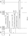
- FIG. 5 shows an example signal flow between the UE 300, LTE eNB 202, NR eNB 204A and core network 206 for completing the first handover.
- a handover request signal is transmitted from the LTE eNB 202 to the NR eNB 204A.
- a handover request acknowledgement signal is transmitted from the NR eNB 204A to the LTE eNB 202. It is noted that the handover request signal and the handover request acknowledgement signal are examples of handover related control signalling.
- the LTE eNB 202 transmits a radio resource control (RRC) connection reconfiguration signal to the UE 300.
- RRC radio resource control
- the UE 300 performs a random access procedure in order to establish a connection with the NR eNB 204A.
- the UE 300 transmits an RCC connection reconfiguration completion signal indicating that the RCC connection reconfiguration is complete to the NR eNB 204A.
- the NR eNB 204A transmits a reconfiguration completion signal indicating that the reconfiguration is complete to the LTE eNB 202.
- a path update procedure is then carried out. It is noted that the first handover procedure essentially swaps the MeNB and SeNB in the interworking arrangement shown in Figure 4 .
- the interworking arrangement shown in Figure 4 in which the NR eNB 204A is tightly interworking in LTE (so that the LTE eNB 202 is the MeNB and the NR eNB 204A is the SeNB) is swapped so that, after the handover, the LTE eNB 202 is tightly interworking in NR (so that the NR eNB 204A is the MeNB and the LTE eNB 202 is the SeNB).
- the LTE eNB 202 is simultaneously the S-MeNB and the T-SeNB.
- the NR eNB 204A is simultaneously the S-SeNB and the T-MeNB.
- the second handover is carried out between the NR eNB 204A and the NR eNB 204B. Since both the NR eNBs 204A and 20B use the same RAT (namely, NR), the second handover is a simple intra-RAT handover and thus is not described in detail here.
- step 506 in Figure 5 may not be necessary, as the UE 300 is already connected to both the LTE eNB 202 and NR eNB 204A as part of the NR-LTE interworking arrangement. Step 506 is thus only required in the case that the random access resources are changed. Furthermore, data forwarding may not be necessary, as the UE 300 keeps the connection with both the LTE eNB 202 and NR eNB 204A and therefore pending transmissions or retransmissions may be completed using the same transport and physical channel configurations.
- Data forwarding may be necessary, however, when moving the anchor Packet Data Convergence Protocol (PDCP) entity across RATs, and the handover involves a reconfiguration that would prevent transmission of pending data on the original configuration, such as a security algorithm change, or radio link control (RLC) reset, or when the LTE eNB 202 is added as SeNB after the handover is finished.
- PDCP Packet Data Convergence Protocol
- RLC radio link control
- the first handover may be initiated, for example, when the UE 300 is part of the coverage area of the interworking arrangement in which the NR eNB 204A is tightly integrated in LTE but is moving towards the coverage area provided by the NR eNB 204B (as indicated by arrow 400).
- the second handover procedure may then be initiated as the UE 300 moves into the coverage area provided by the NR eNB 204B (as indicated by arrow 402).
- a similar procedure to that described with reference to Figures 4 and 5 may be applied during a handover procedure from an arrangement in which NR-1 eNB 204A is tightly interworking in LTE eNB 202 (as shown in Figure 4 ) to an arrangement in which NR-1 eNB 204A acts as a standalone eNB (that is, an eNB which does is not part of a tightly interworking arrangement).
- Figure 6 shows an arrangement of the present disclosure according to another embodiment.
- the arrangement of Figure 6 comprises a UE 300, an LTE eNB 202A as first infrastructure equipment, a first NR eNB 204A as second infrastructure equipment and a second NR eNB 204B as third infrastructure equipment.
- the LTE eNB 202A and NR eNB 204B are again connected to a next generation core network 206.
- the arrangement of Figure 6 also comprises a second LTE eNB 202B as fourth infrastructure equipment. It is noted that, in this embodiment, each of the LTE eNBs 202A and 202B have the structure of the LTE eNB shown in Figure 3B .
- the NR eNB 204B and LTE eNB 202B are operable to form an interworking arrangement (such as an LTE-NR tight interworking arrangement as previously described) in which the NR eNB 204B is an MeNB with which control plane signalling and user plane data is exchangeable with the UE 300 and the LTE eNB 202B is an SeNB with which user plane data is exchangeable with the UE 300.
- an interworking arrangement such as an LTE-NR tight interworking arrangement as previously described
- the handover procedure for the UE thus involves handover from an arrangement in which NR is tightly interworking in LTE (with LTE eNB 202A as MeNB and NR eNB 204A as SeNB) to an arrangement in which LTE is tightly interworking in NR (with NR eNB 204B as MeNB and LTE eNB 202B as SeNB) as the UE 300 travels in the direction of the arrow 600.
- the information necessary for completing the handover which is exchanged between the LTE eNB 202A and the NR eNB 204B via the NR eNB 202A comprises a handover request signal and a handover request acknowledgement signal.
- the LTE eNB 202A is operable to communicate with the LTE eNB 202B using LTE (as the first RAT) so as to allow further information necessary for completing the handover from the LTE eNB 202A as S-MeNB to the NR eNB 204B as T-MeNB to be exchanged between the LTE eNB 202A and the LTE eNB 202B.
- This further information may include, for example, control plane signalling and user plane data which is forwarded from the LTE eNB 202A to the LTE eNB 202B.
- the NR eNB 204A is operable to communicate with the NR eNB 204B using NR (as the second RAT) so as to allow further information necessary for completing the handover from the LTE eNB 202A as S-MeNB to the NR eNB 204B as T-MeNB to be exchanged between the NR eNB 204A and the NR eNB 204B.
- This further information may include, for example, relevant control plane signalling and user plane data which is forwarded from the NR eNB 204A to the NR eNB 204B.
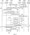
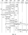
- FIG. 7 An example signal flow between the UE 300, LTE eNB 202A, LTE eNB 202B, NR eNB 204A, NR eNB 204B and core network 206 implemented by the embodiment of Figure 6 is shown in Figure 7 .
- a handover request signal is transmitted from the LTE eNB 202A to the NR eNB 204B via the NR eNB 204A.
- this handover request signal is transmitted from the LTE eNB 202A to the NR eNB 204A using the tight interworking connection between the LTE eNB 202A and NR eNB 204A, and is then transmitted from the NR eNB 204A to the NR eNB 204B at the RAN level using NR.
- the NR eNB 204B transmits a SeNB addition request signal to the LTE eNB 202B.
- the SeNB addition request signal requests that the LTE eNB 202B becomes a SeNB interworking with the NR eNB 204B as a MeNB, thus establishing the interworking arrangement between the NR eNB 204B and the LTE eNB 202B.
- the LTE eNB 202B transmits an addition request acknowledgement signal to the NR eNB 204B.
- the addition request acknowledgement signal indicates to the NR eNB 204B that the LTE eNB 202B is able to become a SeNB interworking with the NR eNB 204B as a MeNB.
- a handover request acknowledgement signal is transmitted from the NR eNB 204B to the LTE eNB 202A via the NR eNB 204A.
- this handover request acknowledgement signal is transmitted from the NR eNB 204B to the NR eNB 204A at the RAN level using NR, and is then transmitted from the NR eNB 204A to the LTE eNB 202A using the tight interworking connection between the NR eNB 204A and the LTE eNB 202A.
- an RRC connection reconfiguration signal is transmitted from the LTE eNB 202A to the UE 300.
- the UE 300 performs a random access procedure in order to establish a connection with the NR eNB 204B.
- the UE 300 transmits an RCC connection reconfiguration completion signal indicating that the RCC connection reconfiguration is complete to the NR eNB 204B.
- the UE 300 performs a random access procedure in order to establish a connection with the LTE eNB 202B.
- the NR eNB 204B transmits a SeNB reconfiguration completion signal to the LTE eNB 204B. This indicates to the LTE eNB 204B that the reconfiguration to make the LTE eNB 204B the SeNB in the interworking arrangement with the NR eNB 202B as MeNB is complete.
- the LTE eNB 202A forwards, respectively, relevant control plane signalling and user plane data to the LTE eNB 202B at the RAN level using LTE.
- the NR eNB 204A forwards, respectively, relevant control plane signalling and user plane data to the NR eNB 204B at the RAN level using NR.
- a path update procedure is implemented.
- an S-SeNB release procedure is implemented. This releases the NR eNB 204A, thus ending the interworking arrangement between the LTE eNB 202A and the NR eNB 204A.
- the NR eNB 204B (now the MeNB, with the LTE eNB 202B as the SeNB) transmits a UE context release signal to the LTE eNB 202A (as source MeNB).
- the LTE eNB 202A then transmits a context release signal to the NR eNB 204A (as source SeNB) at step 732. This completes the handover procedure.
- the handover concept depicted in Figures 4 and 5 may be extended to the arrangement of Figure 6 .
- the first handover can adopt the procedure as depicted in Figure 5 .
- Figure 8 shows an arrangement of the present disclosure according to another embodiment.
- the embodiment of Figure 8 is the same as that of Figure 6 , except that, this time, the LTE eNB 202A is connected to an EPC core network 200 whereas the NR eNB 204B is connected to a next generation core network 206.
- the signalling flow may be different depending when the S-SeNB connection (that is, the connection between the UE 300 and the NR eNB 204A) is released during the handover. Two different example signalling flows are given with reference to Figures 9 and 10 .
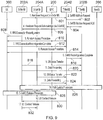
- FIG. 9 An first example signal flow between the UE 300, LTE eNB 202A, LTE eNB 202B, NR eNB 204A, NR eNB 204B, core network 206 and core network 200 implemented by the embodiment of Figure 8 is shown in Figure 9 .
- the S-SeNB in this case, the NR eNB 204A
- the NR eNB 204A will not be released until the path update procedure is finished.
- the source MeNB in this case, LTE eNB 202A
- target SeNB in this case, LTE eNB 202B
- target SeNB in this case, LTE eNB 202B
- target MeNB in this case, NR eNB 204B
- target MeNB in this case, NR eNB 204B
- the source SeNB is then released once the path update procedure is finished.
- a handover request signal is transmitted from the LTE eNB 202A to the NR eNB 204B via the NR eNB 204A. More specifically, this handover request signal is transmitted from the LTE eNB 202A to the NR eNB 204A using the tight interworking connection between the LTE eNB 202A and NR eNB 204A, and is then transmitted from the NR eNB 204A to the NR eNB 204B at the RAN level using NR.
- the handover request signal could be transmitted directly from eNB 202A (as S-MeNB) to eNB 204B (as T-MeNB).
- the NR eNB 204B transmits a SeNB addition request signal to the LTE eNB 202B.
- the SeNB addition request signal requests that the LTE eNB 202B becomes a SeNB interworking with the NR eNB 204B as a MeNB, thus establishing the interworking arrangement between the NR eNB 204B and the LTE eNB 202B.
- the LTE eNB 202B transmits an addition request acknowledgement signal to the NR eNB 204B.
- the addition request acknowledgement signal indicates to the NR eNB 204B that the LTE eNB 202B is able to become a SeNB interworking with the NR eNB 204B as a MeNB.
- a handover request acknowledgement signal is transmitted from the NR eNB 204B to the LTE eNB 202A via the NR eNB 204A. More specifically, this handover request acknowledgement signal is transmitted from the NR eNB 204B to the NR eNB 204A at the RAN level using NR, and is then transmitted from the NR eNB 204A to the LTE eNB 202A using the tight interworking connection between the NR eNB 204A and the LTE eNB 202A.
- the handover request acknowledgement signal could be transmitted directly from eNB 204B (as T-MeNB) to eNB 202A (as S-MeNB)
- an RRC connection reconfiguration signal is transmitted from the LTE eNB 202A to the UE 300.
- the RRC connection reconfiguration signal may include configurations (for example, radio resource configuration, system information or the like) to add the NR eNB 204B as a target MeNB as well as configurations (for example, radio resource configuration, system information or the like) to add LTE eNB 202B as a target SeNB.
- the UE 300 performs a random access procedure in order to establish a connection with the NR eNB 204B.
- the UE 300 transmits an RCC connection reconfiguration completion signal indicating that the RCC connection reconfiguration is complete to the NR eNB 204B.
- the UE 300 performs a random access procedure in order to establish a connection with the LTE eNB 202B.
- the NR eNB 204B transmits a SeNB reconfiguration completion signal to the LTE eNB 204B. This indicates to the LTE eNB 204B that the reconfiguration to make the LTE eNB 204B the SeNB in the interworking arrangement with the NR eNB 202B as MeNB is complete.
- the LTE eNB 202A forwards, respectively, relevant control plane signalling and user plane data to the LTE eNB 202B at the RAN level using LTE. It will be appreciated that, alternatively, in the case that there is no RAN level interface between eNB 202A and eNB 202B, then the control plane signalling and user plane data may be forwarded via the core network.
- user plane data is forwarded via the eNB 204B (as the T-MeNB) in the case that the user plane is split at the RAN level or directly to the eNB 202B (as the T-SeNB) in the case that the user plane is split at the CN level.
- the NR eNB 204A forwards, respectively, relevant control plane signalling and user plane data to the NR eNB 204B at the RAN level using NR.
- SCG secondary cell group
- the NR eNB 204B (now the MeNB, with the LTE eNB 202B as the SeNB) transmits a UE context release signal to the LTE eNB 202A (as source MeNB).
- the LTE eNB 202A then transmits a context release signal to the NR eNB 204A (as source SeNB) at step 832. This completes the handover procedure.
- FIG. 10 An second example signal flow between the UE 300, LTE eNB 202A, LTE eNB 202B, NR eNB 204A, NR eNB 204B, core network 206 and core network 200 implemented by the embodiment of Figure 8 is shown in Figure 10 .
- the S-SeNB in this case, the NR eNB 204A
- the source MeNB in this case, LTE eNB 202A
- the target MeNB in this case, LTE eNB 202B
- the target SeNB cells may then be added after the handover to the target MeNB is complete, for example.
- a detailed description of Figure 10 is now provided.
- a handover request signal is transmitted from the LTE eNB 202A to the NR eNB 204B.
- the handover request signal may be transmitted via the CN 200 (as an example of a first core network) and CN 206 (as an example of a second core network) in the case that there is a control interface between the two CNs, for example.
- the handover request signal could be transmitted directly from eNB 202A (as S-MeNB) to eNB 204B (as T-MeNB) using this RAN level interface.
- a handover request acknowledgement signal is transmitted from the NR eNB 204B to the LTE eNB 202A.
- the handover request acknowledgement signal may be transmitted via the CNs 200 and 206 in the case that there is a control interface between the two CNs, for example.
- the handover request acknowledgement signal could be transmitted directly from eNB 204B (as T-MeNB) to eNB 202A (as S-MeNB) using this RAN level interface.
- an S-SeNB release signal is transmitted from the LTE eNB 202A (as S-MeNB) to the NR eNB 204A (as S-SeNB).
- This signal indicates to the NR eNB 204A that it is to be released as S-SeNB, thus ending the interworking arrangement between the LTE eNB 202A and the NR eNB 204A.
- an RRC connection reconfiguration signal is transmitted from the LTE eNB 202A to the UE 300.
- the RRC connection reconfiguration signal may include configurations (for example, radio resource configuration, system information or the like) to add the NR eNB 204B as a target MeNB as well as configurations (for example, radio resource configuration, system information or the like) to release the NR eNB 204A as a source SeNB.
- the UE 300 performs a random access procedure in order to establish a connection with the NR eNB 204B.
- the UE 300 transmits an RCC connection reconfiguration completion signal indicating that the RCC connection reconfiguration is complete to, respectively, the NR eNB 204B (as T-MeNB) and the LTE eNB 202A (as S-MeNB).
- the NR eNB 204A (as S-SeNB) forwards, respectively, relevant control plane signalling and user plane data to the LTE eNB 202A (as S-MeNB).
- the LTE eNB 202A (as S-MeNB) forwards, respectively, relevant control plane signalling and user plane data to the NR eNB 204B (as T-MeNB).
- the data packets forwarded in this case include data packets from the LTE eNB 202A as well as data packets from the NR eNB 204A.
- the forwarding of control plane signalling and user plane data in steps 1018 and 1020 may be carried out via the CNs 200 and 206 in the case that there is a control interface between the two CNs, for example.
- the handover request signal could be transmitted directly from eNB 202A (as S-MeNB) to eNB 204B (as T-MeNB) using this RAN level interface.
- eNB 202A as S-MeNB
- eNB 204B as T-MeNB
- a path update procedure is implemented.
- the NR eNB 204B (as target MeNB) transmits a UE context release signal to the LTE eNB 202A (as source MeNB).
- the LTE eNB 202A (as source MeNB) then transmits a context release signal to the NR eNB 204A (as source SeNB) at step 832. This completes the handover procedure so that the NR eNB 204B is now the MeNB.
- a suitable target SeNB (this being LTE eNB 202B in the example of Figure 8 ) is then added at step 1028 using a suitable procedure.
- the NR eNB 204B (as target MeNB) knows which target SeNB cell could be added for the UE (for example, based on UE downlink (DL) measurement reporting or the measurement of an uplink (UL) reference signal from the UE), then the target SeNB addition procedure could be implemented at an earlier stage during the signalling flow (rather than at step 1028).
- DL downlink
- UL uplink
- the eNB 204B (as T-MeNB) could notify eNB 202A (as S-MeNB) of the identity of the target SeNB, and the RRC connection reconfiguration signal transmitted from the eNB 202A to the UE 300 at step 1006 could include configurations (for example, radio resource configuration, system information or the like) for adding the target SeNB.
- configurations for example, radio resource configuration, system information or the like
- handover of the UE 300 in accordance with the present technique is described.
- handover can be initiated on the basis of the measurement of downlink or uplink signals.
- the serving cell of the UE 300 (which may be the MeNB or SeNB of an interworking arrangement) will configure the UE to perform an inter-RAT measurement by, for example, dedicated signalling.
- the UE will perform a suitable measurement on the signal strength and/or quality of a downlink reference signal transmitted from each eNB it its vicinity, whether that eNB is operating under a first RAT (for example, LTE) or a second RAT (for example, NR).
- the UE 300 will then generate a measurement report and transmit this measurement report to the serving cell.
- the serving cell or another suitable component of the network, such as the CN 200 or 206) then determines whether a handover is necessary.
- a handover is necessary from the NR eNB 204A (as SeNB) interworking with the LTE eNB 202A (as MeNB) to the LTE eNB 202B (as SeNB) interworking with the NR eNB 204B (as MeNB) when the measurement report indicates that a reference signal from the NR eNB 204B has a better strength and/or quality than the reference signal from the LTE eNB 202A.
- Handover is then initiated by the LTE eNB 202A by transmission of a handover request signal, as previously described.
- handover is initiated on the basis of an uplink reference signal transmitted from the UE 300.
- the transmission of the UE uplink reference signal may be implemented in one of a number of ways.
- the UE 300 is configured to generate a measurement report and transmit the measurement report to the serving cell in the same way as for the downlink measurement case described in the previous paragraph.
- the UE in response to it being determined that handover should take place (due to, for example, a deteriorating signal strength and/or quality of the radio link with the serving cell), instead of the serving cell or CN determining the target eNB for handover on the basis of information in the measurement report, the UE is configured (by dedicated signalling or the like) to begin transmitting an uplink reference signal (in the form of a beacon signal, for example).
- an uplink reference signal in the form of a beacon signal, for example.
- This uplink reference signal is then measured by the eNBs in the vicinity of the UE so as to allow handover to be made to a target eNB with the highest measured signal strength and/or quality of the uplink reference signal.
- This example may be particularly relevant to handover from LTE to NR, since it uses the existing downlink measurement reporting of LTE in order to determine that handover is necessary (due to, for example, a deteriorating signal strength and/or quality of the radio link with the LTE serving cell), but then determines the target eNB on the basis of an uplink reference signal transmitted by the UE, thus allowing handover to an NR eNB for NR configurations which utilise UE uplink reference signals in order to carry out handover operations.
- Such an arrangement thus allows existing provisions in LTE (namely, downlink measurement reporting) to be used in order to implement inter-RAT mobility.
- the need for handover is determined on the basis of the measurement of an uplink reference signal by the serving cell. That is, the UE transmits an uplink reference signal which is measured by the serving cell so as to determine whether handover should take place.
- this uplink reference signal is measured by the eNBs in the vicinity of the UE so as to allow handover to be made to a target eNB with the highest measured signal strength and/or quality of the uplink reference signal.
- the serving cell may configure its neighbouring cells to measure the uplink reference signal from the UE. Each of the neighbour cells will then generate a measurement report of the uplink reference signal and send corresponding measurement report to the serving cell, thus allowing the serving cell to make a decision on the target eNB for the handover.
- the UE 300 may be configured to continuously or periodically (on the basis of discontinuous transmission (DTX) or the like) transmit the uplink reference signal.
- the UE 300 may be configured to initiate transmission of the uplink reference signal in response to it reaching the edge of coverage of its current cell. This may be carried out on the basis of UE location reporting, for example.
- FIG 11 shows a flow chart schematically illustrating a process according to the present technique.
- the process starts at step 1100.
- first infrastructure equipment such as LTE eNB 202A
- a terminal device such as UE 300
- second infrastructure equipment such as NR eNB 204A
- the first infrastructure equipment is a master infrastructure equipment with which control plane signalling and user plane data is exchangeable with the terminal device
- the second infrastructure equipment is a secondary infrastructure equipment with which user plane data is exchangeable with the terminal device.
- the second infrastructure equipment is controlled to communicate with the third infrastructure equipment using the second RAT so as to allow information necessary for completing the handover to be exchanged between the first infrastructure equipment and the third infrastructure equipment via the second infrastructure equipment.
- the process then ends at step 1106.
- Described embodiments may be implemented in any suitable form including hardware, software, firmware or any combination of these. Described embodiments may optionally be implemented at least partly as computer software running on one or more data processors and/or digital signal processors.
- the elements and components of any embodiment may be physically, functionally and logically implemented in any suitable way. Indeed the functionality may be implemented in a single unit, in a plurality of units or as part of other functional units. As such, the disclosed embodiments may be implemented in a single unit or may be physically and functionally distributed between different units, circuitry and/or processors.
Landscapes
- Engineering & Computer Science (AREA)
- Computer Networks & Wireless Communication (AREA)
- Signal Processing (AREA)
- Mobile Radio Communication Systems (AREA)
Description
- The present disclosure relates to telecommunications system, terminal device, infrastructure equipment and methods, and in particular, but not exclusively, to methods and apparatus for controlling handover procedures in wireless telecommunications systems.
- The "background" description provided herein is for the purpose of generally presenting the context of the disclosure. Work of the presently named inventors, to the extent it is described in this background section, as well as aspects of the description which may not otherwise qualify as prior art at the time of filing, are neither expressly or impliedly admitted as prior art against the present invention.
- Third and fourth generation mobile telecommunication systems, such as those based on the 3GPP defined UMTS and Long Term Evolution (LTE) architecture are able to support more sophisticated services than simple voice and messaging services offered by previous generations of mobile telecommunication systems. For example, with the improved radio interface and enhanced data rates provided by LTE systems, a user is able to enjoy high data rate applications such as mobile video streaming and mobile video conferencing that would previously only have been available via a fixed line data connection. The demand to deploy third and fourth generation networks is therefore strong and the coverage area of these networks, i.e. geographic locations where access to the networks is possible, is expected to increase rapidly. However, whilst fourth generation networks can support communications at high data rate and low latencies from devices such as smart phones and tablet computers, it is expected that future wireless communications networks, will be expected to efficiently support communications with a much wider range of devices associated with a wider range of data traffic profiles, for example including reduced complexity devices, machine type communication devices, high resolution video displays and virtual reality headsets. Some of these different types of devices may be deployed in very large numbers, for example low complexity devices for supporting the "The Internet of Things", and may typically be associated with the transmissions of relatively small amounts of data with relatively high latency tolerance, whereas other types of device, for example supporting high-definition video streaming, may be associated with transmissions of relatively large amounts of data with relatively low latency tolerance.
- There is therefore expected to be a desire for future wireless communications networks, which may be referred to as 5G or new radio access technology (which may be denoted new RAT or, simply, NR) networks, to efficiently support connectivity for a wide range of devices associated with different applications with different characteristic data traffic profiles, resulting in different devices have different operating characteristics / requirements, such as:
- High latency tolerance
- High data rates
- Millimetre wave spectrum use
- High density of network nodes (e.g. small cell and relay nodes)
- Large system capacity
- Large numbers of devices (e.g. MTC devices / Internet of Things devices)
- High reliability (e.g. for vehicle safety applications, such as self-driving cars).
- Low device cost and energy consumption
- Flexible spectrum usage
- Flexible mobility
- The introduction of new radio access technology (RAT) systems / networks therefore gives rise to new challenges for providing efficient operation for devices operating in new RAT networks, including devices able to operate in both new RAT networks (e.g. a 3GPP 5G network) and currently deployed RAT networks (e.g. a 3GPP 4G network). One particular area where new approaches may be helpful is in relation to handovers between network nodes responsible for communicating with a terminal device, which may be referred to as mobility management. It will be appreciated that handovers may result from a device physically moving between coverage areas of different cells or from changing radio conditions associated with different cells for a static device, and the term mobility management may be used for both scenarios.
- With current mobile telecommunications systems, such as those based on the 3GPP defined UMTS and Long Term Evolution (LTE) based architectures, handover procedures are carried out on the basis of measurements of downlink signals broadcast by each of the network nodes. These measurements are performed by terminal devices and network node selection, reselection or handover is then performed on the basis of these measurements so as to allow each terminal device to communicate with the network.
- However, existing approaches for handling mobility, with the associated measurement report signalling, handover signalling and evaluation procedures, require a relatively large number of messages to be exchanged, which results in a relatively high control signalling overhead and increased chance of handover failure, particularly in the case of small cells and/or fast moving terminal devices, because of the time taken to perform the measurements and signalling. This is a problem which is likely to need particular consideration in view of the introduction of NR systems. In particular, there is a need to efficiently manage mobility between network nodes operating using existing RATs (such as LTE) and network nodes operating using new RATs.
- There is therefore a desire to provide for new approaches for handling mobility in wireless telecommunications systems.
- Prior art includes ERICSSON, "NR/LTE tight interworking: CP requirements on Mobility and Dual Connectivity", vol. RAN WG2, no. Nanjing, China; 20160523 - 20160527, (20160522), 3GPP DRAFT; R2-163993 - NR-LTE TIGHT INTERWORKING CP REQUIREMENTS ON MOBILITY AND DUAL CONNECTIVITY, 3RD GENERATION PARTNERSHIP PROJECT (3GPP), MOBILE COMPETENCE CENTRE ; 650, ROUTE DES LUCIOLES ; F-0, URL: http://www.3gpp.org/ftp/Meetings_3GPP_SYNC/RAN2/Docs/.
- The present disclosure can help address or mitigate at least some of the issues discussed above.
- Respective aspects and features of the present disclosure are defined in the appended claims.
- It is to be understood that both the foregoing general description and the following detailed description are exemplary, but are not restrictive, of the present technology. The described embodiments, together with further advantages, will be best understood by reference to the following detailed description taken in conjunction with the accompanying drawings.
- A more complete appreciation of the disclosure and many of the attendant advantages thereof will be readily obtained as the same becomes better understood by reference to the following detailed description when considered in connection with the accompanying drawings wherein like reference numerals designate identical or corresponding parts throughout the several views, and wherein:
-
Figure 1 schematically represents some elements of a conventional LTE-based mobile telecommunications network / system; -
Figures 2A-F schematically show a number of different possible scenarios of tight interworking in a mobile telecommunications network/system; -
Figures 3A-C schematically show a terminal device, an eNB operating in accordance with a first RAT and an eNB operating in accordance with a second RAT, the first RAT being different to the second RAT; -
Figure 4 schematically shows an arrangement of the present disclosure according to one embodiment; -
Figure 5 schematically shows a signalling flow associated with the embodiment ofFigure 4 ; -
Figure 6 schematically shows an arrangement of the present disclosure according to another embodiment; -
Figure 7 schematically shows a signalling flow associated with the embodiment ofFigure 6 ; -
Figure 8 schematically shows an arrangement of the present disclosure according to another embodiment; -
Figure 9 schematically shows a first example signalling flow associated with the embodiment ofFigure 8 ; -
Figure 10 schematically shows a second example signalling flow associated with the embodiment ofFigure 8 ; and -
Figure 11 shows a flow chart schematically illustrating a process according to the present technique. -
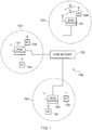
Figure 1 is a schematic diagram illustrating a network architecture for an LTE-based wireless mobile telecommunications network /system 100. Various elements ofFigure 1 and their respective modes of operation are well-known and defined in the relevant standards administered by the 3GPP (RTM) body, and also described in many books on the subject, for example, Holma H. and Toskala A [1]. It will be appreciated that operational aspects of the telecommunications network represented inFigure 1 , and of other networks discussed herein in accordance with embodiments of the disclosure, which are not specifically described (for example in relation to specific communication protocols and physical channels for communicating between different elements) may be implemented in accordance with any known techniques, for example according to currently used approaches for implementing such operational aspects of wireless telecommunications systems, e.g. in accordance with the relevant standards. - The
network 100 includes a plurality ofbase stations 101 connected to acore network 102. Each base station provides a coverage area 103 (i.e. a cell) within which data can be communicated to and fromterminal devices 104. Data is transmitted frombase stations 101 toterminal devices 104 within theirrespective coverage areas 103 via a radio downlink. Data is transmitted fromterminal devices 104 to thebase stations 101 via a radio uplink. Thecore network 102 routes data to and from theterminal devices 104 via therespective base stations 101 and provides functions such as authentication, mobility management, charging and so on. Terminal devices may also be referred to as mobile stations, user equipment (UE), user terminal, mobile radio, communications device, and so forth. Base stations, which are an example of network infrastructure equipment, may also be referred to as transceiver stations / nodeBs / e-nodeBs (eNBs), and so forth. - In terms of broad top-level functionality, the network architecture of a new RAT will have a similar general arrangement to that shown for current LTE networks in
Figure 1 . In particular, a new RAT network architecture will include a core network component, a number of base stations and a number of terminal devices which operate together so as to allow exchange of data between terminal devices on the network. It will be appreciated that operational aspects of a new RAT network (for example in relation to specific communication protocols and physical channels for communicating between different elements) may be different to those known from LTE or other known mobile telecommunications standards. However, it will also be appreciated that each of the core network component, base stations and terminal devices of a new RAT network will be functionally similar to, respectively, the core network component, base stations and terminal devices ofFigure 1 . In particular, in the new RAT, each base station will be connected to the core network. Each base station will provide a coverage area (i.e. a cell) within which data can be communicated to and from terminal devices. Data will be transmitted from base stations to terminal devices within their respective coverage areas via a radio downlink. Data will be transmitted from terminal devices to the base stations via a radio uplink. The core network will route data to and from the terminal devices via the respective base stations. This functional equivalence is sufficient for an understanding of the present technique. - In 3GPP a Study Item (SI) on New Radio Access Technology (NR) has been agreed [2]. This SI is to study and to develop a new Radio Access Technology (RAT) for the next generation wireless communication system, i.e. 5G. The new RAT is expected to operate in a large range of frequencies, from hundreds of MHz to 100 GHz and it is expected to cover a broad range of use cases. The use cases that are considered under this SI are:
- Enhanced Mobile Broadband (eMBB)
- Massive Machine Type Communications (mMTC)
- Ultra Reliable & Low Latency Communications (URLLC).
- In 5G, there are in general two operational modes. These are a tight interworking mode and standalone mode. In tight interworking mode, a 5G NR eNodeB works together with an LTE eNodeB. This may occur using an approach similar to, for example, dual connectivity (as known in LTE), and may include, for example, the LTE eNodeB working as an anchor eNodeB for the 5G NR eNodeB. On the other hand, in standalone mode, a 5G NR eNodeB could work independently without the assistance of an LTE eNodeB. Both of these two operational modes are discussed in [3], for example. The present disclosure relates particularly to managing handover in tight interworking mode in an efficient manner.
- In tight interworking mode, a number of different scenarios are possible. These are illustrated in
Figures 2A-F . -
Figures 2A and 2B each show a tight interworking mode in which NR is tightly integrated in LTE via an Evolved Packet Core (EPC) core network 200 (known from LTE). In this case, anLTE eNB 202 forms a master eNB (MeNB) with which both control plane (CP) signalling and user plane (UP) data is exchangeable with a terminal device of the network and anNR eNB 204 forms a secondary eNB (SeNB) with which only UP data is exchangeable with a terminal device of the network (that is, no CP signalling is exchangeable between the NR eNB and a terminal device).Figure 2A shows an arrangement in which the UP data is split at the core network (CN) 200 so that all UP data may be exchanged between the NR eNB 204 (SeNB) and theCN 200 without having to go via the LTE eNB 202 (MeNB).Figure 2B shows an alternative arrangement in which UP data is split at the radio access network (RAN) level so that all UP data exchanged between the NR eNB 204 (SeNB) and theCN 200 is exchanged via the LTE eNB 202 (MeNB). -
Figures 2C and 2D each show a tight interworking mode in which LTE is tightly integrated in NR via a nextgeneration core network 206. Such a next generation core network (CN) may be standardised so as to interoperate with NR, for example. Specific details of thenext generation CN 206 are not required for an understanding of the present technique, however. In this scenario, anNR eNB 204 forms a master eNB (MeNB) with which both control plane (CP) signalling and user plane (UP) data is exchangeable with a terminal device of the network and anLTE eNB 202 forms a secondary eNB (SeNB) with which only UP data is exchangeable with a terminal device of the network (that is, no CP signalling is exchangeable between the LTE eNB and a terminal device).Figure 2C shows an arrangement in which the UP data is split at the core network (CN) 206 so that all UP data may be exchanged between the LTE eNB 202 (SeNB) and theCN 206 without having to go via the NR eNB 204 (MeNB).Figure 2B shows an alternative arrangement in which UP data is split at the radio access network (RAN) level so that all UP data exchanged between the LTE eNB 202 (SeNB) and theCN 206 is exchanged via the NR eNB 204 (MeNB). -
Figures 2E and 2F each show a tight interworking mode in which NR is again tightly integrated in LTE. This time, however, the tight integration occurs vianext generation CN 206 rather thanEPC 200. This situation remains similar to that shown inFigures 2A and 2B , however. In this case, anLTE eNB 202 forms a master eNB (MeNB) with which both control plane (CP) signalling and user plane (UP) data is exchangeable with a terminal device of the network and anNR eNB 204 forms a secondary eNB (SeNB) with which only UP data is exchangeable with a terminal device of the network (that is, no CP signalling is exchangeable between the NR eNB and a terminal device).Figure 2E shows an arrangement in which the UP data is split at the core network (CN) 206 so that all UP data may be exchanged between the NR eNB 204 (SeNB) and theCN 206 without having to go via the LTE eNB 202 (MeNB).Figure 2F shows an alternative arrangement in which UP data is split at the radio access network (RAN) level so that all UP data exchanged between the NR eNB 204 (SeNB) and theCN 206 is exchanged via the LTE eNB 202 (MeNB). - With the tight interworking network arrangements shown in
Figures 2A-F , it is desirable to enable handover from one tight interworking network arrangement to another whilst reducing the core network signalling overhead and mitigating data packet loss. In particular, this is desirable when handing over from a first tight interworking arrangement with a MeNB operating using a first RAT (such as LTE) and a SeNB operating using a second RAT (such as NR) to a second tight interworking arrangement with a MeNB operating using the second RAT (such as NR) and a SeNB operating using the first RAT (such as LTE). The present technique is thus principally directed to this scenario. - In order to help describe the present technique,
Figures 3A-C schematically show a terminal device, an eNB operating in accordance with a first RAT and an eNB operating in accordance with a second RAT, the first RAT being different to the second RAT. In this particular example, the first RAT is LTE and the second RAT is NR. -
Figure 3A shows aterminal device 300. Theterminal device 300 comprises atransmitter 306 configured to transmit wireless signals, areceiver 304 configured to receive wireless signals and acontroller 302 configured to control theterminal device 300. Thetransmitter 306 andreceiver 304 together form a transceiver.Figure 3B shows anLTE eNB 202. TheeNB 202 operates in accordance with LTE, LTE being the first RAT. TheeNB 202 comprises atransmitter 312 configured to transmit wireless signals, areceiver 310 configured to receive wireless signals and acontroller 308 configured to control theeNB 202. Thetransmitter 312 andreceiver 310 together form a transceiver.Figure 3C shows aNR eNB 204. TheeNB 204 operates in accordance with NR, NR being the second RAT. TheeNB 204 comprises atransmitter 318 configured to transmit wireless signals, areceiver 316 configured to receive wireless signals and acontroller 314 configured to control theeNB 204. Thetransmitter 318 andreceiver 316 together form a transceiver. In the following description, it will be appreciated that signals which are transmitted and received between aterminal device 300 and another network entity are, respectively, transmitted by thetransmitter 306 and received by thereceiver 304 under control of thecontroller 302. Also, signals which are transmitted and received between anLTE eNB 202 and another network entity are, respectively, transmitted by thetransmitter 312 and received by thereceiver 310 under control of thecontroller 308. Similarly, signals which are transmitted and received between anNR eNB 202 and another network entity are, respectively, transmitted by thetransmitter 318 and received by thereceiver 316 under control of thecontroller 314. The operation of a wireless telecommunications system comprising one or moreterminal devices 300, one ormore LTE eNBs 202 and one ormore NR eNBs 204 in accordance with the present technique is controlled by one or more of thecontrollers - According to an arrangement of the present disclosure, there is provided wireless telecommunications system. The wireless telecommunications system comprises a terminal device, first infrastructure equipment, second infrastructure equipment and third infrastructure equipment. The first infrastructure equipment is operable to communicate with the terminal device using a first RAT and the second infrastructure equipment is operable to communicate with the terminal device using a second RAT. The first RAT is different to the second RAT. For example, the first RAT may be LTE whereas the second RAT may be NR. The first infrastructure equipment and second infrastructure equipment form an interworking arrangement (such as an LTE-NR tight interworking arrangement as previously described) in which the first infrastructure equipment is a master infrastructure equipment (such as an MeNB) with which control plane signalling and user plane data is exchangeable with the terminal device and the second infrastructure equipment (such as a SeNB) is a secondary infrastructure equipment with which user plane data is exchangeable with the terminal device. The third infrastructure equipment is operable to communicate with the terminal device using the second RAT. During a handover procedure for handover from the first infrastructure equipment as a source master infrastructure equipment to the third infrastructure equipment as a target master infrastructure equipment, the second infrastructure equipment is operable to communicate with the third infrastructure equipment - using an interface associated with the second RAT (for example, a RAN interface associated with the second RAT) so as to allow information necessary for completing the handover to be exchanged between the first infrastructure equipment and the third infrastructure equipment via the second infrastructure equipment. Thus, with the present disclosure, the information necessary for completing the handover is exchanged between the first infrastructure equipment and the third infrastructure equipment via the second infrastructure equipment rather than via the core network. The signalling overhead associated with the core network is therefore reduced. In addition, due to the time saved for completing handover due to the reduction in the amount of information which needs to be exchanged via the core network, data packet loss is alleviated.
-
Figure 4 shows an arrangement of the present disclosure according to one embodiment. The arrangement ofFigure 4 comprises aUE 300, anLTE eNB 202 as first infrastructure equipment, afirst NR eNB 204A as second infrastructure equipment and asecond NR eNB 204B as third infrastructure equipment. TheLTE eNB 202 andNR eNB 204B are connected to a nextgeneration core network 206. In this case, it will be appreciated that LTE is the first RAT and NR is the second RAT. In the arrangement ofFigure 4 , the handover procedure for theUE 300 comprises a first handover and a second handover. The first handover occurs fromLTE eNB 202 as a source MeNB (S-MeNB) toNR eNB 204A as a target MeNB (T-MeNB). In this case, information necessary for completing the first handover is exchanged between theLTE eNB 202 and theNR eNB 204A on the basis of the interworking arrangement (tight interworking arrangement) formed byLTE eNB 202 and theNR eNB 204A. The second handover then occurs from theNR eNB 204A as an S-MeNB toNR eNB 204B as a T-MeNB. In this case, information necessary for completing the second handover is exchanged between theNR eNB 204A and theNR eNB 204B at the RAN (radio access network) level using NR. It is noted that each of theNR eNBs Figure 3C . In this embodiment, it will be appreciated that information necessary for completing the handover is exchanged between the LTE eNB 202 (as first infrastructure equipment) andNR eNB 204B (as third infrastructure equipment) via theNR eNB 204A (as second infrastructure equipment) by splitting the handover procedure into the first and second handovers. -
Figure 5 shows an example signal flow between theUE 300,LTE eNB 202,NR eNB 204A andcore network 206 for completing the first handover. Firstly, atstep 500, a handover request signal is transmitted from theLTE eNB 202 to theNR eNB 204A. Atstep 502, a handover request acknowledgement signal is transmitted from theNR eNB 204A to theLTE eNB 202. It is noted that the handover request signal and the handover request acknowledgement signal are examples of handover related control signalling. Atstep 504, theLTE eNB 202 transmits a radio resource control (RRC) connection reconfiguration signal to theUE 300. Atstep 506, theUE 300 performs a random access procedure in order to establish a connection with theNR eNB 204A. Atstep 508, theUE 300 transmits an RCC connection reconfiguration completion signal indicating that the RCC connection reconfiguration is complete to theNR eNB 204A. Atstep 510, theNR eNB 204A transmits a reconfiguration completion signal indicating that the reconfiguration is complete to theLTE eNB 202. Atstep 512, a path update procedure is then carried out. It is noted that the first handover procedure essentially swaps the MeNB and SeNB in the interworking arrangement shown inFigure 4 . That is, the interworking arrangement shown inFigure 4 in which theNR eNB 204A is tightly interworking in LTE (so that theLTE eNB 202 is the MeNB and theNR eNB 204A is the SeNB) is swapped so that, after the handover, theLTE eNB 202 is tightly interworking in NR (so that theNR eNB 204A is the MeNB and theLTE eNB 202 is the SeNB). In this sense, for the first handover, theLTE eNB 202 is simultaneously the S-MeNB and the T-SeNB. Similarly, theNR eNB 204A is simultaneously the S-SeNB and the T-MeNB. Once the first handover is completed, the second handover is carried out between theNR eNB 204A and theNR eNB 204B. Since both theNR eNBs 204A and 20B use the same RAT (namely, NR), the second handover is a simple intra-RAT handover and thus is not described in detail here. - It is noted that, in some embodiments,
step 506 inFigure 5 may not be necessary, as theUE 300 is already connected to both theLTE eNB 202 andNR eNB 204A as part of the NR-LTE interworking arrangement. Step 506 is thus only required in the case that the random access resources are changed. Furthermore, data forwarding may not be necessary, as theUE 300 keeps the connection with both theLTE eNB 202 andNR eNB 204A and therefore pending transmissions or retransmissions may be completed using the same transport and physical channel configurations. Data forwarding may be necessary, however, when moving the anchor Packet Data Convergence Protocol (PDCP) entity across RATs, and the handover involves a reconfiguration that would prevent transmission of pending data on the original configuration, such as a security algorithm change, or radio link control (RLC) reset, or when theLTE eNB 202 is added as SeNB after the handover is finished. - In the embodiment of
Figure 4 , the first handover may be initiated, for example, when theUE 300 is part of the coverage area of the interworking arrangement in which theNR eNB 204A is tightly integrated in LTE but is moving towards the coverage area provided by theNR eNB 204B (as indicated by arrow 400). The second handover procedure may then be initiated as theUE 300 moves into the coverage area provided by theNR eNB 204B (as indicated by arrow 402). - It is noted that, in another embodiment, a similar procedure to that described with reference to
Figures 4 and5 may be applied during a handover procedure from an arrangement in which NR-1eNB 204A is tightly interworking in LTE eNB 202 (as shown inFigure 4 ) to an arrangement in which NR-1eNB 204A acts as a standalone eNB (that is, an eNB which does is not part of a tightly interworking arrangement). -
Figure 6 shows an arrangement of the present disclosure according to another embodiment. Like the arrangement ofFigure 4 , the arrangement ofFigure 6 comprises aUE 300, anLTE eNB 202A as first infrastructure equipment, afirst NR eNB 204A as second infrastructure equipment and asecond NR eNB 204B as third infrastructure equipment. TheLTE eNB 202A andNR eNB 204B are again connected to a nextgeneration core network 206. However, the arrangement ofFigure 6 also comprises asecond LTE eNB 202B as fourth infrastructure equipment. It is noted that, in this embodiment, each of theLTE eNBs Figure 3B . - In this embodiment, the
NR eNB 204B andLTE eNB 202B are operable to form an interworking arrangement (such as an LTE-NR tight interworking arrangement as previously described) in which theNR eNB 204B is an MeNB with which control plane signalling and user plane data is exchangeable with theUE 300 and theLTE eNB 202B is an SeNB with which user plane data is exchangeable with theUE 300. The handover procedure for the UE thus involves handover from an arrangement in which NR is tightly interworking in LTE (withLTE eNB 202A as MeNB andNR eNB 204A as SeNB) to an arrangement in which LTE is tightly interworking in NR (withNR eNB 204B as MeNB andLTE eNB 202B as SeNB) as theUE 300 travels in the direction of thearrow 600. In this embodiment, the information necessary for completing the handover which is exchanged between theLTE eNB 202A and theNR eNB 204B via theNR eNB 202A comprises a handover request signal and a handover request acknowledgement signal. Furthermore, in this embodiment, theLTE eNB 202A is operable to communicate with theLTE eNB 202B using LTE (as the first RAT) so as to allow further information necessary for completing the handover from theLTE eNB 202A as S-MeNB to theNR eNB 204B as T-MeNB to be exchanged between theLTE eNB 202A and theLTE eNB 202B. This further information may include, for example, control plane signalling and user plane data which is forwarded from theLTE eNB 202A to theLTE eNB 202B. Similarly, theNR eNB 204A is operable to communicate with theNR eNB 204B using NR (as the second RAT) so as to allow further information necessary for completing the handover from theLTE eNB 202A as S-MeNB to theNR eNB 204B as T-MeNB to be exchanged between theNR eNB 204A and theNR eNB 204B. This further information may include, for example, relevant control plane signalling and user plane data which is forwarded from theNR eNB 204A to theNR eNB 204B. - An example signal flow between the
UE 300,LTE eNB 202A,LTE eNB 202B,NR eNB 204A,NR eNB 204B andcore network 206 implemented by the embodiment ofFigure 6 is shown inFigure 7 . Atstep 700, a handover request signal is transmitted from theLTE eNB 202A to theNR eNB 204B via theNR eNB 204A. More specifically, this handover request signal is transmitted from theLTE eNB 202A to theNR eNB 204A using the tight interworking connection between theLTE eNB 202A andNR eNB 204A, and is then transmitted from theNR eNB 204A to theNR eNB 204B at the RAN level using NR. Atstep 702, theNR eNB 204B transmits a SeNB addition request signal to theLTE eNB 202B. The SeNB addition request signal requests that theLTE eNB 202B becomes a SeNB interworking with theNR eNB 204B as a MeNB, thus establishing the interworking arrangement between theNR eNB 204B and theLTE eNB 202B. Atstep 704, theLTE eNB 202B transmits an addition request acknowledgement signal to theNR eNB 204B. The addition request acknowledgement signal indicates to theNR eNB 204B that theLTE eNB 202B is able to become a SeNB interworking with theNR eNB 204B as a MeNB. Atstep 706, a handover request acknowledgement signal is transmitted from theNR eNB 204B to theLTE eNB 202A via theNR eNB 204A. More specifically, this handover request acknowledgement signal is transmitted from theNR eNB 204B to theNR eNB 204A at the RAN level using NR, and is then transmitted from theNR eNB 204A to theLTE eNB 202A using the tight interworking connection between theNR eNB 204A and theLTE eNB 202A. Atstep 708, an RRC connection reconfiguration signal is transmitted from theLTE eNB 202A to theUE 300. Atstep 710, theUE 300 performs a random access procedure in order to establish a connection with theNR eNB 204B. Atstep 712, theUE 300 transmits an RCC connection reconfiguration completion signal indicating that the RCC connection reconfiguration is complete to theNR eNB 204B. Atstep 714, theUE 300 performs a random access procedure in order to establish a connection with theLTE eNB 202B. Atstep 716, theNR eNB 204B transmits a SeNB reconfiguration completion signal to theLTE eNB 204B. This indicates to theLTE eNB 204B that the reconfiguration to make theLTE eNB 204B the SeNB in the interworking arrangement with theNR eNB 202B as MeNB is complete. Atsteps LTE eNB 202A forwards, respectively, relevant control plane signalling and user plane data to theLTE eNB 202B at the RAN level using LTE. Similarly, atsteps NR eNB 204A forwards, respectively, relevant control plane signalling and user plane data to theNR eNB 204B at the RAN level using NR. Atstep 726, a path update procedure is implemented. Atstep 728, an S-SeNB release procedure is implemented. This releases theNR eNB 204A, thus ending the interworking arrangement between theLTE eNB 202A and theNR eNB 204A. Atstep 730, theNR eNB 204B (now the MeNB, with theLTE eNB 202B as the SeNB) transmits a UE context release signal to theLTE eNB 202A (as source MeNB). TheLTE eNB 202A then transmits a context release signal to theNR eNB 204A (as source SeNB) atstep 732. This completes the handover procedure. - It will be appreciated that, with the present embodiment, by exchanging certain information necessary for completing the handover (such as the handover request/handover request acknowledgement signals (
steps 700, 706) and the control plane signalling and user plane data (steps - It is noted that the handover concept depicted in
Figures 4 and5 (including the initial swap of which eNB in an interworking arrangement is the MeNB) may be extended to the arrangement ofFigure 6 . For example, there may be a first handover fromNR eNB 204A tightly interworking withLTE eNB 202A toLTE eNB 202A tightly interworking withNR eNB 204A (this essentially constituting a swap from theLTE eNB 202A being the MeNB in the interworking arrangement to theNR eNB 204A being the MeNB in the interworking arrangement). There may then be a second handover (this being an intra-RAT inter-MeNB handover) fromLTE eNB 202A tightly interworking withNR eNB 204A toLTE eNB 202B tightly interworking withNR eNB 204B. In this case, the first handover can adopt the procedure as depicted inFigure 5 . -
Figure 8 shows an arrangement of the present disclosure according to another embodiment. The embodiment ofFigure 8 is the same as that ofFigure 6 , except that, this time, theLTE eNB 202A is connected to anEPC core network 200 whereas theNR eNB 204B is connected to a nextgeneration core network 206. In this case, in order to facilitate handover as theUE 300 moves in the direction ofarrow 800, the signalling flow may be different depending when the S-SeNB connection (that is, the connection between theUE 300 and theNR eNB 204A) is released during the handover. Two different example signalling flows are given with reference toFigures 9 and10 . - An first example signal flow between the
UE 300,LTE eNB 202A,LTE eNB 202B,NR eNB 204A,NR eNB 204B,core network 206 andcore network 200 implemented by the embodiment ofFigure 8 is shown inFigure 9 . With this scheme, the S-SeNB (in this case, theNR eNB 204A) will not be released until the path update procedure is finished. In order to reduce the core level signalling overhand and alleviate data packet loss, the source MeNB (in this case,LTE eNB 202A) will forward the data packets to target SeNB (in this case,LTE eNB 202B) if there is a RAN interface between them (which there is in this case, the RAN interface being an LTE interface). Similarly, the source SeNB (in this case,NR eNB 204A) will forward the data packets to target MeNB (in this case,NR eNB 204B) if there is a RAN interface between them (which there is in this case, the RAN interface being an NR interface). The source SeNB is then released once the path update procedure is finished. A detailed description ofFigure 9 is now provided. - At
step 801, a handover request signal is transmitted from theLTE eNB 202A to theNR eNB 204B via theNR eNB 204A. More specifically, this handover request signal is transmitted from theLTE eNB 202A to theNR eNB 204A using the tight interworking connection between theLTE eNB 202A andNR eNB 204A, and is then transmitted from theNR eNB 204A to theNR eNB 204B at the RAN level using NR. Alternatively, in the case that there is a RAN level interface betweeneNB 202A andeNB 204B (for example, in the case that both eNBs used LTE or NR), then it will be appreciated that the handover request signal could be transmitted directly fromeNB 202A (as S-MeNB) toeNB 204B (as T-MeNB). Atstep 802, theNR eNB 204B transmits a SeNB addition request signal to theLTE eNB 202B. The SeNB addition request signal requests that theLTE eNB 202B becomes a SeNB interworking with theNR eNB 204B as a MeNB, thus establishing the interworking arrangement between theNR eNB 204B and theLTE eNB 202B. Atstep 804, theLTE eNB 202B transmits an addition request acknowledgement signal to theNR eNB 204B. The addition request acknowledgement signal indicates to theNR eNB 204B that theLTE eNB 202B is able to become a SeNB interworking with theNR eNB 204B as a MeNB. Atstep 806, a handover request acknowledgement signal is transmitted from theNR eNB 204B to theLTE eNB 202A via theNR eNB 204A. More specifically, this handover request acknowledgement signal is transmitted from theNR eNB 204B to theNR eNB 204A at the RAN level using NR, and is then transmitted from theNR eNB 204A to theLTE eNB 202A using the tight interworking connection between theNR eNB 204A and theLTE eNB 202A. Alternatively, in the case that there is a RAN level interface betweeneNB 202A andeNB 204B (for example, in the case that both eNBs used LTE or NR), then it will be appreciated that the handover request acknowledgement signal could be transmitted directly fromeNB 204B (as T-MeNB) toeNB 202A (as S-MeNB) Atstep 808, an RRC connection reconfiguration signal is transmitted from theLTE eNB 202A to theUE 300. The RRC connection reconfiguration signal may include configurations (for example, radio resource configuration, system information or the like) to add theNR eNB 204B as a target MeNB as well as configurations (for example, radio resource configuration, system information or the like) to addLTE eNB 202B as a target SeNB. Atstep 810, theUE 300 performs a random access procedure in order to establish a connection with theNR eNB 204B. Atstep 812, theUE 300 transmits an RCC connection reconfiguration completion signal indicating that the RCC connection reconfiguration is complete to theNR eNB 204B. Atstep 814, theUE 300 performs a random access procedure in order to establish a connection with theLTE eNB 202B. Atstep 816, theNR eNB 204B transmits a SeNB reconfiguration completion signal to theLTE eNB 204B. This indicates to theLTE eNB 204B that the reconfiguration to make theLTE eNB 204B the SeNB in the interworking arrangement with theNR eNB 202B as MeNB is complete. Atsteps LTE eNB 202A forwards, respectively, relevant control plane signalling and user plane data to theLTE eNB 202B at the RAN level using LTE. It will be appreciated that, alternatively, in the case that there is no RAN level interface betweeneNB 202A andeNB 202B, then the control plane signalling and user plane data may be forwarded via the core network. In this case, user plane data is forwarded via theeNB 204B (as the T-MeNB) in the case that the user plane is split at the RAN level or directly to theeNB 202B (as the T-SeNB) in the case that the user plane is split at the CN level. Similarly, atsteps NR eNB 204A forwards, respectively, relevant control plane signalling and user plane data to theNR eNB 204B at the RAN level using NR. Alternatively, in the case that there is no RAN level interface betweeneNB 204A andeNB 204B, secondary cell group (SCG) data packets for theeNB 204A (when theeNB 204A belongs to a SCG) may be discarded, or, as the radio link between the UE andeNB 204A is still alive at this stage of the signalling flow, if the user plane is split at the CN level, then SCG data packets can continuously be exchanged with theUE 300 via theeNB 204A (as the S-SeNB) until handover is complete. Atstep 826, a path update procedure is implemented. Atstep 828, an S-SeNB release procedure is implemented. This releases theNR eNB 204A as S-SeNB, thus ending the interworking arrangement between theLTE eNB 202A and theNR eNB 204A. Atstep 830, theNR eNB 204B (now the MeNB, with theLTE eNB 202B as the SeNB) transmits a UE context release signal to theLTE eNB 202A (as source MeNB). TheLTE eNB 202A then transmits a context release signal to theNR eNB 204A (as source SeNB) atstep 832. This completes the handover procedure. - An second example signal flow between the
UE 300,LTE eNB 202A,LTE eNB 202B,NR eNB 204A,NR eNB 204B,core network 206 andcore network 200 implemented by the embodiment ofFigure 8 is shown inFigure 10 . With this scheme, the S-SeNB (in this case, theNR eNB 204A) is released much earlier during the handover procedure. In this case, the source MeNB (in this case,LTE eNB 202A) will forward the data packets from itself as well as the data packets from the source SeNB (in this case,NR eNB 204A) to the target MeNB (in this case,LTE eNB 202B). The target SeNB cells may then be added after the handover to the target MeNB is complete, for example. A detailed description ofFigure 10 is now provided. - At
step 1000, a handover request signal is transmitted from theLTE eNB 202A to theNR eNB 204B. The handover request signal may be transmitted via the CN 200 (as an example of a first core network) and CN 206 (as an example of a second core network) in the case that there is a control interface between the two CNs, for example. Alternatively, in the case that there is a RAN level interface betweeneNB 202A andeNB 204B (for example, in the case that both eNBs used LTE or NR), then it will be appreciated that the handover request signal could be transmitted directly fromeNB 202A (as S-MeNB) toeNB 204B (as T-MeNB) using this RAN level interface. Atstep 1002, a handover request acknowledgement signal is transmitted from theNR eNB 204B to theLTE eNB 202A. Again, the handover request acknowledgement signal may be transmitted via theCNs eNB 202A andeNB 204B (for example, in the case that both eNBs used LTE or NR), then it will be appreciated that the handover request acknowledgement signal could be transmitted directly fromeNB 204B (as T-MeNB) toeNB 202A (as S-MeNB) using this RAN level interface. Atstep 1004, an S-SeNB release signal is transmitted from theLTE eNB 202A (as S-MeNB) to theNR eNB 204A (as S-SeNB). This signal indicates to theNR eNB 204A that it is to be released as S-SeNB, thus ending the interworking arrangement between theLTE eNB 202A and theNR eNB 204A. Atstep 1006, an RRC connection reconfiguration signal is transmitted from theLTE eNB 202A to theUE 300. The RRC connection reconfiguration signal may include configurations (for example, radio resource configuration, system information or the like) to add theNR eNB 204B as a target MeNB as well as configurations (for example, radio resource configuration, system information or the like) to release theNR eNB 204A as a source SeNB. Atstep 1008, theUE 300 performs a random access procedure in order to establish a connection with theNR eNB 204B. Atsteps UE 300 transmits an RCC connection reconfiguration completion signal indicating that the RCC connection reconfiguration is complete to, respectively, theNR eNB 204B (as T-MeNB) and theLTE eNB 202A (as S-MeNB). Atsteps NR eNB 204A (as S-SeNB) forwards, respectively, relevant control plane signalling and user plane data to theLTE eNB 202A (as S-MeNB). Atsteps LTE eNB 202A (as S-MeNB) forwards, respectively, relevant control plane signalling and user plane data to theNR eNB 204B (as T-MeNB). The data packets forwarded in this case include data packets from theLTE eNB 202A as well as data packets from theNR eNB 204A. The forwarding of control plane signalling and user plane data insteps CNs eNB 202A andeNB 204B (for example, in the case that both eNBs used LTE or NR), then it will be appreciated that the handover request signal could be transmitted directly fromeNB 202A (as S-MeNB) toeNB 204B (as T-MeNB) using this RAN level interface. Atstep 1022, a path update procedure is implemented. Atstep 1024, theNR eNB 204B (as target MeNB) transmits a UE context release signal to theLTE eNB 202A (as source MeNB). TheLTE eNB 202A (as source MeNB) then transmits a context release signal to theNR eNB 204A (as source SeNB) atstep 832. This completes the handover procedure so that theNR eNB 204B is now the MeNB. A suitable target SeNB (this beingLTE eNB 202B in the example ofFigure 8 ) is then added atstep 1028 using a suitable procedure. In an alternative example, if theNR eNB 204B (as target MeNB) knows which target SeNB cell could be added for the UE (for example, based on UE downlink (DL) measurement reporting or the measurement of an uplink (UL) reference signal from the UE), then the target SeNB addition procedure could be implemented at an earlier stage during the signalling flow (rather than at step 1028). For example, theeNB 204B (as T-MeNB) could notifyeNB 202A (as S-MeNB) of the identity of the target SeNB, and the RRC connection reconfiguration signal transmitted from theeNB 202A to theUE 300 atstep 1006 could include configurations (for example, radio resource configuration, system information or the like) for adding the target SeNB. - In the above-described examples, various implementations of handover of the
UE 300 in accordance with the present technique are described. Of course, it will be appreciated that before such handover can be implemented, it must be decided to undertake a handover operation in the first place. It is envisaged that handover can be initiated on the basis of the measurement of downlink or uplink signals. - In the case of downlink measurement, the serving cell of the UE 300 (which may be the MeNB or SeNB of an interworking arrangement) will configure the UE to perform an inter-RAT measurement by, for example, dedicated signalling. In this case, the UE will perform a suitable measurement on the signal strength and/or quality of a downlink reference signal transmitted from each eNB it its vicinity, whether that eNB is operating under a first RAT (for example, LTE) or a second RAT (for example, NR). The
UE 300 will then generate a measurement report and transmit this measurement report to the serving cell. On the basis of this measurement report, the serving cell (or another suitable component of the network, such as theCN 200 or 206) then determines whether a handover is necessary. For example, in the above-described examples, it may be determined that a handover is necessary from theNR eNB 204A (as SeNB) interworking with theLTE eNB 202A (as MeNB) to theLTE eNB 202B (as SeNB) interworking with theNR eNB 204B (as MeNB) when the measurement report indicates that a reference signal from theNR eNB 204B has a better strength and/or quality than the reference signal from theLTE eNB 202A. Handover is then initiated by theLTE eNB 202A by transmission of a handover request signal, as previously described. - In the case of uplink measurement, handover is initiated on the basis of an uplink reference signal transmitted from the
UE 300. The transmission of the UE uplink reference signal may be implemented in one of a number of ways. - In one example, the
UE 300 is configured to generate a measurement report and transmit the measurement report to the serving cell in the same way as for the downlink measurement case described in the previous paragraph. However, in this case, in response to it being determined that handover should take place (due to, for example, a deteriorating signal strength and/or quality of the radio link with the serving cell), instead of the serving cell or CN determining the target eNB for handover on the basis of information in the measurement report, the UE is configured (by dedicated signalling or the like) to begin transmitting an uplink reference signal (in the form of a beacon signal, for example). This uplink reference signal is then measured by the eNBs in the vicinity of the UE so as to allow handover to be made to a target eNB with the highest measured signal strength and/or quality of the uplink reference signal. This example may be particularly relevant to handover from LTE to NR, since it uses the existing downlink measurement reporting of LTE in order to determine that handover is necessary (due to, for example, a deteriorating signal strength and/or quality of the radio link with the LTE serving cell), but then determines the target eNB on the basis of an uplink reference signal transmitted by the UE, thus allowing handover to an NR eNB for NR configurations which utilise UE uplink reference signals in order to carry out handover operations. Such an arrangement thus allows existing provisions in LTE (namely, downlink measurement reporting) to be used in order to implement inter-RAT mobility. - In another example, a similar arrangement exists. However, this time, instead of the need for handover being determined on the basis of downlink measurement reporting, the need for handover is determined on the basis of the measurement of an uplink reference signal by the serving cell. That is, the UE transmits an uplink reference signal which is measured by the serving cell so as to determine whether handover should take place. In response to it being determined that handover should take place (due to, for example, a deteriorating signal strength and/or quality of the radio link with the serving cell, as determined on the basis of the uplink reference signal), this uplink reference signal is measured by the eNBs in the vicinity of the UE so as to allow handover to be made to a target eNB with the highest measured signal strength and/or quality of the uplink reference signal. In this case, for example, the serving cell may configure its neighbouring cells to measure the uplink reference signal from the UE. Each of the neighbour cells will then generate a measurement report of the uplink reference signal and send corresponding measurement report to the serving cell, thus allowing the serving cell to make a decision on the target eNB for the handover. It is noted that the
UE 300 may be configured to continuously or periodically (on the basis of discontinuous transmission (DTX) or the like) transmit the uplink reference signal. Alternatively, theUE 300 may be configured to initiate transmission of the uplink reference signal in response to it reaching the edge of coverage of its current cell. This may be carried out on the basis of UE location reporting, for example. - It will be appreciated that, although the above-described examples are directed to handover from NR interworking in LTE to LTE interworking in NR, the same examples would also apply from, for example, handover from LTE interworking in NR to NR interworking in LTE. More generally, it will be appreciated that the above-described examples may apply to handover from a first RAT interworking in a second RAT to the second RAT interworking in the first RAT, wherein the first and second RATs are different.
-
Figure 11 shows a flow chart schematically illustrating a process according to the present technique. The process starts atstep 1100. Atstep 1102, first infrastructure equipment (such asLTE eNB 202A) operable to communicate with a terminal device (such as UE 300) using a first RAT and second infrastructure equipment (such asNR eNB 204A) operable to communicate with the terminal device using a second RAT are controlled to form an interworking arrangement in which the first infrastructure equipment is a master infrastructure equipment with which control plane signalling and user plane data is exchangeable with the terminal device and the second infrastructure equipment is a secondary infrastructure equipment with which user plane data is exchangeable with the terminal device. Atstep 1104, during a handover procedure for handover from the first infrastructure equipment as a source master infrastructure equipment to third infrastructure equipment (such asNR eNB 204B) as a target master infrastructure equipment, the second infrastructure equipment is controlled to communicate with the third infrastructure equipment using the second RAT so as to allow information necessary for completing the handover to be exchanged between the first infrastructure equipment and the third infrastructure equipment via the second infrastructure equipment. The process then ends atstep 1106. - In so far as embodiments of the disclosure have been described as being implemented, at least in part, by software-controlled data processing apparatus, it will be appreciated that a non-transitory machine-readable medium carrying such software, such as an optical disk, a magnetic disk, semiconductor memory or the like, is also considered to represent an embodiment of the present disclosure.
- It will be appreciated that the above description for clarity has described embodiments with reference to different functional units, circuitry and/or processors. However, it will be apparent that any suitable distribution of functionality between different functional units, circuitry and/or processors may be used without detracting from the embodiments.
- Described embodiments may be implemented in any suitable form including hardware, software, firmware or any combination of these. Described embodiments may optionally be implemented at least partly as computer software running on one or more data processors and/or digital signal processors. The elements and components of any embodiment may be physically, functionally and logically implemented in any suitable way. Indeed the functionality may be implemented in a single unit, in a plurality of units or as part of other functional units. As such, the disclosed embodiments may be implemented in a single unit or may be physically and functionally distributed between different units, circuitry and/or processors.
-
- [1] Holma H. and Toskala A, "LTE for UMTS OFDMA and SC-FDMA based radio access", John Wiley and Sons, 2009
- [2] RP-160671: New SID Proposal: Study on New Radio Access Technology
- [3] R2-162364. Deployment Scenarios for Interworking. Nokia, Alcatel-Lucent Shanghai Bell.
Claims (7)
- A wireless telecommunications system comprising:a terminal device (300);first infrastructure equipment (202) configured to communicate with the terminal device using a first radio access technology, RAT, and second infrastructure equipment (204A) configured to communicate with the terminal device using a second RAT, the first RAT being one of Long Term Evolution, LTE, and New Radio Access Technology, NR, and the second RAT being the other of LTE and NR, wherein the first infrastructure equipment and second infrastructure equipment form a first interworking arrangement in which the first infrastructure equipment is a master infrastructure equipment with which control plane signalling and user plane data is exchangeable with the terminal device and the second infrastructure equipment is a secondary infrastructure equipment with which user plane data is exchangeable with the terminal device; anda third infrastructure equipment (204B) configured to communicate with the terminal device, using the first or the second RAT;wherein:during a handover procedure for handover from the first infrastructure equipment as a source master infrastructure equipment to the third infrastructure equipment as a target master infrastructure equipment, the second infrastructure equipment is configured to communicate with the third infrastructure equipment using an interface, associated with the first or the second RAT; so as to allow information necessary for completing the handover to be exchanged between the first infrastructure equipment and the third infrastructure equipment via the second infrastructure equipment;wherein the wireless telecommunications system further comprises:a fourth infrastructure equipment configured to communicate with the terminal device using the first RAT, wherein the third infrastructure equipment and fourth infrastructure equipment are configured to form a second interworking arrangement in which the third infrastructure equipment is a master infrastructure equipment with which control plane signalling and user plane data is exchangeable with the terminal device and the fourth infrastructure equipment is a secondary infrastructure equipment with which user plane data is exchangeable with the terminal device;wherein:
the information necessary for completing the handover which is exchanged between the first infrastructure equipment and the third infrastructure equipment via the second infrastructure equipment comprises handover related control signalling. - A wireless telecommunications system according to claim 1, wherein the handover procedure comprises:a first handover from the first infrastructure equipment as a source master infrastructure equipment to the second infrastructure equipment as a target master infrastructure equipment, wherein information necessary for completing the first handover is exchanged between the first infrastructure equipment and the second infrastructure equipment on the basis of the interworking arrangement formed by the first infrastructure equipment and the second infrastructure equipment; anda second handover from the second infrastructure equipment as a source master infrastructure equipment to the third infrastructure equipment as a target master infrastructure equipment, wherein information necessary for completing the second handover is exchanged between the second infrastructure equipment and the third infrastructure equipment using the interface associated with the second RAT.
- A wireless telecommunications system according to claim 2, wherein, during the handover procedure:
the first infrastructure equipment is configured to communicate with the fourth infrastructure equipment using an interface associated with the first RAT so as to allow further information necessary for completing the handover from the first infrastructure equipment as a source master infrastructure equipment to the third infrastructure equipment as a target master infrastructure equipment to be exchanged between the first infrastructure equipment and the fourth infrastructure equipment; and
the second infrastructure equipment is configured to communicate with the third infrastructure equipment using the interface associated with the second RAT so as to allow further information necessary for completing the handover from the first infrastructure equipment as a source master infrastructure equipment to the third infrastructure equipment as a target master infrastructure equipment to be exchanged between the second infrastructure equipment and the third infrastructure equipment. - A wireless telecommunications system according to claim 1, wherein the first RAT is Long Term Evolution (LTE) and the second RAT is a New Radio Access Technology (NR).
- A wireless telecommunications system according to claim 3, wherein:the first RAT is Long Term Evolution (LTE) and the second RAT is a New Radio Access Technology (NR);the further information to be exchanged between the first infrastructure equipment and the fourth infrastructure equipment comprises control plane signalling and user plane data which are forwarded from the first infrastructure equipment to the fourth infrastructure equipment; and
the further information to be exchanged between the second infrastructure equipment and the third infrastructure equipment comprises control plane signalling and user plane data which are forwarded from the second infrastructure equipment to the third infrastructure equipment. - A method of operating a wireless telecommunications system comprising a terminal device (300), first infrastructure equipment (202) configured to communicate with the terminal device using a first radio access technology, RAT, second infrastructure equipment (204A) configured to communicate with the terminal device using a second RAT, the first RAT being one of Long Term Evolution, LTE, and New Radio Access Technology, NR, and the second RAT being the other of LTE and NR, and third infrastructure equipment (204B) configured to communicate with the terminal device, using the first or the second RAT, wherein the method comprises:integrated circuitry controlling (1102) the first infrastructure equipment and second infrastructure equipment to form a first interworking arrangement in which the first infrastructure equipment is a master infrastructure equipment with which control plane signalling and user plane data is exchangeable with the terminal device and the second infrastructure equipment is a secondary infrastructure equipment with which user plane data is exchangeable with the terminal device; andintegrated circuitry controlling (1104), during a handover procedure for handover from the first infrastructure equipment as a source master infrastructure equipment to the third infrastructure equipment as a target master infrastructure equipment, the second infrastructure equipment to communicate with the third infrastructure equipment using an interface associated with the first or second RAT so as to allow information necessary for completing the handover to be exchanged between the first infrastructure equipment and the third infrastructure equipment via the second infrastructure equipment;wherein the wireless telecommunications system further comprises a fourth infrastructure equipment configured to communicate with the terminal device using the first RAT and wherein the method comprises:integrated circuitry controlling the third infrastructure equipment and fourth infrastructure equipment to form second interworking arrangement in which the third infrastructure equipment is a master infrastructure equipment with which control plane signalling and user plane data is exchangeable with the terminal device and the fourth infrastructure equipment is a secondary infrastructure equipment with which user plane data is exchangeable with the terminal device;wherein:
the information necessary for completing the handover which is exchanged between the first infrastructure equipment and the third infrastructure equipment via the second infrastructure equipment comprises handover related control signalling. - Integrated circuitry for a wireless telecommunications system comprising a terminal device, first infrastructure equipment (202) configured to communicate with the terminal device (300) using a first radio access technology, RAT, second infrastructure equipment (204A) configured to communicate with the terminal device using a second RAT, the first RAT being one of Long Term Evolution, LTE, and New Radio Access Technology, NR, and the second RAT being the other of LTE and NR, and third infrastructure equipment (204B) configured to communicate with the terminal device using the first or second RAT, wherein the integrated circuitry is configured to:control the first infrastructure equipment and second infrastructure equipment to form a first interworking arrangement in which the first infrastructure equipment is a master infrastructure equipment with which control plane signalling and user plane data is exchangeable with the terminal device and the second infrastructure equipment is a secondary infrastructure equipment with which user plane data is exchangeable with the terminal device; andcontrol, during a handover procedure for handover from the first infrastructure equipment as a source master infrastructure equipment to the third infrastructure equipment as a target master infrastructure equipment, the second infrastructure equipment to communicate with the third infrastructure equipment using an interface associated with the first or the second RAT so as to allow information necessary for completing the handover to be exchanged between the first infrastructure equipment and the third infrastructure equipment via the second infrastructure equipment;wherein the wireless telecommunications system further comprises a fourth infrastructure equipment configured to communicate with the terminal device using the first RAT and wherein the integrated circuitry is configured to:control the third infrastructure equipment and fourth infrastructure equipment to form a second interworking arrangement in which the third infrastructure equipment is a master infrastructure equipment with which control plane signalling and user plane data is exchangeable with the terminal device and the fourth infrastructure equipment is a secondary infrastructure equipment with which user plane data is exchangeable with the terminal device;wherein:
the information necessary for completing the handover which is exchanged between the first infrastructure equipment and the third infrastructure equipment via the second infrastructure equipment comprises handover related control signalling.
Applications Claiming Priority (2)
| Application Number | Priority Date | Filing Date | Title |
|---|---|---|---|
| EP16183964 | 2016-08-12 | ||
| PCT/EP2017/068249 WO2018028957A1 (en) | 2016-08-12 | 2017-07-19 | Telecommunications system, terminal device, infrastructure equipment and methods |
Publications (2)
| Publication Number | Publication Date |
|---|---|
| EP3497972A1 EP3497972A1 (en) | 2019-06-19 |
| EP3497972B1 true EP3497972B1 (en) | 2021-04-28 |
Family
ID=56683827
Family Applications (1)
| Application Number | Title | Priority Date | Filing Date |
|---|---|---|---|
| EP17743005.5A Active EP3497972B1 (en) | 2016-08-12 | 2017-07-19 | Telecommunications system, terminal device, infrastructure equipment and methods |
Country Status (3)
| Country | Link |
|---|---|
| US (3) | US10893449B2 (en) |
| EP (1) | EP3497972B1 (en) |
| WO (1) | WO2018028957A1 (en) |
Families Citing this family (16)
| Publication number | Priority date | Publication date | Assignee | Title |
|---|---|---|---|---|
| US11159994B2 (en) * | 2017-01-05 | 2021-10-26 | Sony Group Corporation | Uplink signal based handover control, handover cancellation and handover expiration |
| MX2019010749A (en) * | 2017-03-14 | 2019-10-21 | Ericsson Telefon Ab L M | Providing communication for a mobile communication device using a central unit node and distributed unit nodes. |
| US10827474B2 (en) | 2017-05-09 | 2020-11-03 | Qualcomm Incorporated | Techniques and apparatuses for nesting a new radio system and a long term evolution system |
| KR102329925B1 (en) | 2017-08-14 | 2021-11-23 | 삼성전자 주식회사 | A method and apparatus to support data synchronization for 4G/5G dual registered UE |
| US10785817B2 (en) * | 2017-09-28 | 2020-09-22 | Apple Inc. | Signaling radio bearer type 3 (SRB3) and secondary cell group (SCG) failure handling |
| US10980075B2 (en) * | 2018-03-29 | 2021-04-13 | Telefonaktiebolaget Lm Ericsson (Publ) | Slicing of network resources for dual connectivity using NR |
| US11184821B2 (en) | 2018-08-09 | 2021-11-23 | Qualcomm Incorporated | Inter-system handover between standalone mode and non-standalone mode |
| US10736003B2 (en) * | 2018-09-27 | 2020-08-04 | Verizon Patent And Licensing Inc. | Anchor management for dual connectivity devices |
| KR102664931B1 (en) * | 2018-10-29 | 2024-05-09 | 삼성전자주식회사 | Method and apparatus for improving handover performance |
| EP3997931A1 (en) * | 2019-07-08 | 2022-05-18 | Nokia Technologies Oy | Discontinuous transmission, dtx, detection |
| WO2021062863A1 (en) * | 2019-10-02 | 2021-04-08 | Qualcomm Incorporated | Parallel handover and failure handling |
| CN114503663B (en) * | 2019-12-11 | 2024-03-22 | Oppo广东移动通信有限公司 | Communication scene switching method and device, terminal equipment and network equipment |
| US11985553B2 (en) | 2020-01-29 | 2024-05-14 | Qualcomm Incorporated | Techniques for inter-system handing over from a standalone to a non-standalone mode |
| WO2021159336A1 (en) * | 2020-02-12 | 2021-08-19 | Nokia Shanghai Bell Co., Ltd. | Handover to dual connectivity |
| EP4122287B1 (en) | 2020-04-21 | 2025-07-23 | Google LLC | Managing a ue preferred configuration |
| US12082065B2 (en) * | 2021-05-13 | 2024-09-03 | Mediatek Inc. | Session continuity for 3GPP and non-3GPP interworking |
Family Cites Families (12)
| Publication number | Priority date | Publication date | Assignee | Title |
|---|---|---|---|---|
| KR101206557B1 (en) * | 2006-06-20 | 2012-11-29 | 인터디지탈 테크날러지 코포레이션 | Methods and system for performing handover in a wireless communication system |
| US8982841B2 (en) * | 2011-10-27 | 2015-03-17 | Spidercloud Wireless, Inc. | Long term evolution architecture and mobility |
| US9386618B2 (en) * | 2012-08-03 | 2016-07-05 | Futurewei Technologies, Inc. | System and method to support multiple radio access technology relays with a unified backhaul transport network |
| US9538387B2 (en) * | 2012-09-28 | 2017-01-03 | Telefonaktiebolaget Lm Ericsson (Publ) | Radio resource assignment coordination in superdense networks |
| US9622134B2 (en) * | 2013-05-06 | 2017-04-11 | Qualcomm Incorporated | Coordinating handover events across RATs |
| JP6442038B2 (en) * | 2014-03-28 | 2018-12-19 | ノキア ソリューションズ アンド ネットワークス オサケユキチュア | Method and apparatus for handover in dual connectivity of user equipment and base station |
| JP2017528993A (en) * | 2014-09-19 | 2017-09-28 | 日本電気株式会社 | Device for dual connectivity (DUAL CONNECTIVITY) |
| US9538563B2 (en) * | 2014-10-13 | 2017-01-03 | At&T Intellectual Property I, L.P. | System and methods for managing a user data path |
| EP3582547B1 (en) * | 2014-12-30 | 2021-02-03 | Lg Electronics Inc. | Method and apparatus for performing inter-menb handover without senb change in a wireless communication system |
| CN105992295A (en) * | 2015-03-03 | 2016-10-05 | 中兴通讯股份有限公司 | A method for transmitting data in base station handover, user equipment and base station |
| WO2017053742A1 (en) * | 2015-09-23 | 2017-03-30 | Convida Wireless, Llc | Aggregated handover in integrated small cell and wifi networks |
| US10257078B2 (en) * | 2016-04-01 | 2019-04-09 | Qualcomm Incorporated | Interworking with legacy radio access technologies for connectivity to next generation core network |
-
2017
- 2017-07-19 WO PCT/EP2017/068249 patent/WO2018028957A1/en not_active Ceased
- 2017-07-19 EP EP17743005.5A patent/EP3497972B1/en active Active
- 2017-07-19 US US16/323,784 patent/US10893449B2/en active Active
-
2021
- 2021-01-11 US US17/145,731 patent/US11627509B2/en active Active
-
2023
- 2023-04-10 US US18/297,650 patent/US12063564B2/en active Active
Non-Patent Citations (1)
| Title |
|---|
| None * |
Also Published As
| Publication number | Publication date |
|---|---|
| US12063564B2 (en) | 2024-08-13 |
| US10893449B2 (en) | 2021-01-12 |
| WO2018028957A1 (en) | 2018-02-15 |
| US11627509B2 (en) | 2023-04-11 |
| US20190182732A1 (en) | 2019-06-13 |
| EP3497972A1 (en) | 2019-06-19 |
| US20230247505A1 (en) | 2023-08-03 |
| US20210136642A1 (en) | 2021-05-06 |
Similar Documents
| Publication | Publication Date | Title |
|---|---|---|
| US12063564B2 (en) | Telecommunications system, terminal device, infrastructure equipment and methods | |
| EP3497967B1 (en) | Communications devices, infrastructure equipment and methods | |
| EP3050395B1 (en) | User equipment and method for device-to-device (d2d) communication | |
| US20190387563A1 (en) | Establishing simultaneous radio connection between a user equipment and two enodebs | |
| US11019543B2 (en) | Methods and system for managing handover procedure in a radio access network | |
| US12439236B2 (en) | Communication method and communication apparatus | |
| US20190349819A1 (en) | Method and apparatus for supporting beam in wireless communication system | |
| EP2592865A1 (en) | Call drop avoidance during radio link failure | |
| US20130070731A1 (en) | Wireless communication system and method for performing handover in such a system | |
| US20150327142A1 (en) | Apparatus, computer-readable medium, and method to support low complexity user equipment | |
| CN105025465B (en) | User terminal location report method, base station, mobile management entity and system | |
| US11297547B2 (en) | Telecommunications apparatus and methods | |
| KR20250060236A (en) | Method and device for triggering inter-cell mobility process | |
| EP4362547A1 (en) | Ue reporting uplink measurements with mpe event indication | |
| CN102378313A (en) | Mobility management entity selecting method and relay node | |
| WO2022189701A1 (en) | Interference coordination for mobility | |
| US12120563B2 (en) | Method and apparatus for secondary base station change in mobile wireless communication system | |
| US12082290B2 (en) | Method and apparatus for performing measurement in and conditional reconfiguration non-terrestrial network | |
| US11832135B2 (en) | Method and apparatus for secondary base station change in mobile wireless communication system | |
| US20130315205A1 (en) | Wireless communication station and transmission interface switching method thereof | |
| EP4437754A1 (en) | Methods, communications devices, and infrastructure equipment | |
| JP2019097198A (en) | Method and apparatus for mobility management |
Legal Events
| Date | Code | Title | Description |
|---|---|---|---|
| STAA | Information on the status of an ep patent application or granted ep patent |
Free format text: STATUS: UNKNOWN |
|
| STAA | Information on the status of an ep patent application or granted ep patent |
Free format text: STATUS: THE INTERNATIONAL PUBLICATION HAS BEEN MADE |
|
| PUAI | Public reference made under article 153(3) epc to a published international application that has entered the european phase |
Free format text: ORIGINAL CODE: 0009012 |
|
| STAA | Information on the status of an ep patent application or granted ep patent |
Free format text: STATUS: REQUEST FOR EXAMINATION WAS MADE |
|
| 17P | Request for examination filed |
Effective date: 20190212 |
|
| AK | Designated contracting states |
Kind code of ref document: A1 Designated state(s): AL AT BE BG CH CY CZ DE DK EE ES FI FR GB GR HR HU IE IS IT LI LT LU LV MC MK MT NL NO PL PT RO RS SE SI SK SM TR |
|
| AX | Request for extension of the european patent |
Extension state: BA ME |
|
| DAV | Request for validation of the european patent (deleted) | ||
| DAX | Request for extension of the european patent (deleted) | ||
| STAA | Information on the status of an ep patent application or granted ep patent |
Free format text: STATUS: EXAMINATION IS IN PROGRESS |
|
| 17Q | First examination report despatched |
Effective date: 20200124 |
|
| GRAP | Despatch of communication of intention to grant a patent |
Free format text: ORIGINAL CODE: EPIDOSNIGR1 |
|
| STAA | Information on the status of an ep patent application or granted ep patent |
Free format text: STATUS: GRANT OF PATENT IS INTENDED |
|
| INTG | Intention to grant announced |
Effective date: 20201119 |
|
| RIC1 | Information provided on ipc code assigned before grant |
Ipc: H04W 36/00 20090101ALN20201106BHEP Ipc: H04W 84/02 20090101ALI20201106BHEP Ipc: H04W 36/14 20090101AFI20201106BHEP |
|
| GRAS | Grant fee paid |
Free format text: ORIGINAL CODE: EPIDOSNIGR3 |
|
| GRAA | (expected) grant |
Free format text: ORIGINAL CODE: 0009210 |
|
| STAA | Information on the status of an ep patent application or granted ep patent |
Free format text: STATUS: THE PATENT HAS BEEN GRANTED |
|
| AK | Designated contracting states |
Kind code of ref document: B1 Designated state(s): AL AT BE BG CH CY CZ DE DK EE ES FI FR GB GR HR HU IE IS IT LI LT LU LV MC MK MT NL NO PL PT RO RS SE SI SK SM TR |
|
| REG | Reference to a national code |
Ref country code: GB Ref legal event code: FG4D |
|
| REG | Reference to a national code |
Ref country code: CH Ref legal event code: EP |
|
| REG | Reference to a national code |
Ref country code: DE Ref legal event code: R096 Ref document number: 602017037609 Country of ref document: DE |
|
| REG | Reference to a national code |
Ref country code: AT Ref legal event code: REF Ref document number: 1388539 Country of ref document: AT Kind code of ref document: T Effective date: 20210515 |
|
| REG | Reference to a national code |
Ref country code: NL Ref legal event code: FP |
|
| REG | Reference to a national code |
Ref country code: IE Ref legal event code: FG4D |
|
| RAP4 | Party data changed (patent owner data changed or rights of a patent transferred) |
Owner name: SONY EUROPE LIMITED Owner name: SONY MOBILE COMMUNICATIONS, INC. Owner name: SONY GROUP CORPORATION |
|
| REG | Reference to a national code |
Ref country code: LT Ref legal event code: MG9D |
|
| RAP2 | Party data changed (patent owner data changed or rights of a patent transferred) |
Owner name: SONY EUROPE LIMITED Owner name: SONY GROUP CORPORATION |
|
| REG | Reference to a national code |
Ref country code: AT Ref legal event code: MK05 Ref document number: 1388539 Country of ref document: AT Kind code of ref document: T Effective date: 20210428 |
|
| PG25 | Lapsed in a contracting state [announced via postgrant information from national office to epo] |
Ref country code: AT Free format text: LAPSE BECAUSE OF FAILURE TO SUBMIT A TRANSLATION OF THE DESCRIPTION OR TO PAY THE FEE WITHIN THE PRESCRIBED TIME-LIMIT Effective date: 20210428 Ref country code: BG Free format text: LAPSE BECAUSE OF FAILURE TO SUBMIT A TRANSLATION OF THE DESCRIPTION OR TO PAY THE FEE WITHIN THE PRESCRIBED TIME-LIMIT Effective date: 20210728 Ref country code: HR Free format text: LAPSE BECAUSE OF FAILURE TO SUBMIT A TRANSLATION OF THE DESCRIPTION OR TO PAY THE FEE WITHIN THE PRESCRIBED TIME-LIMIT Effective date: 20210428 Ref country code: LT Free format text: LAPSE BECAUSE OF FAILURE TO SUBMIT A TRANSLATION OF THE DESCRIPTION OR TO PAY THE FEE WITHIN THE PRESCRIBED TIME-LIMIT Effective date: 20210428 Ref country code: FI Free format text: LAPSE BECAUSE OF FAILURE TO SUBMIT A TRANSLATION OF THE DESCRIPTION OR TO PAY THE FEE WITHIN THE PRESCRIBED TIME-LIMIT Effective date: 20210428 |
|
| PG25 | Lapsed in a contracting state [announced via postgrant information from national office to epo] |
Ref country code: SE Free format text: LAPSE BECAUSE OF FAILURE TO SUBMIT A TRANSLATION OF THE DESCRIPTION OR TO PAY THE FEE WITHIN THE PRESCRIBED TIME-LIMIT Effective date: 20210428 Ref country code: RS Free format text: LAPSE BECAUSE OF FAILURE TO SUBMIT A TRANSLATION OF THE DESCRIPTION OR TO PAY THE FEE WITHIN THE PRESCRIBED TIME-LIMIT Effective date: 20210428 Ref country code: PL Free format text: LAPSE BECAUSE OF FAILURE TO SUBMIT A TRANSLATION OF THE DESCRIPTION OR TO PAY THE FEE WITHIN THE PRESCRIBED TIME-LIMIT Effective date: 20210428 Ref country code: PT Free format text: LAPSE BECAUSE OF FAILURE TO SUBMIT A TRANSLATION OF THE DESCRIPTION OR TO PAY THE FEE WITHIN THE PRESCRIBED TIME-LIMIT Effective date: 20210830 Ref country code: NO Free format text: LAPSE BECAUSE OF FAILURE TO SUBMIT A TRANSLATION OF THE DESCRIPTION OR TO PAY THE FEE WITHIN THE PRESCRIBED TIME-LIMIT Effective date: 20210728 Ref country code: GR Free format text: LAPSE BECAUSE OF FAILURE TO SUBMIT A TRANSLATION OF THE DESCRIPTION OR TO PAY THE FEE WITHIN THE PRESCRIBED TIME-LIMIT Effective date: 20210729 Ref country code: IS Free format text: LAPSE BECAUSE OF FAILURE TO SUBMIT A TRANSLATION OF THE DESCRIPTION OR TO PAY THE FEE WITHIN THE PRESCRIBED TIME-LIMIT Effective date: 20210828 Ref country code: LV Free format text: LAPSE BECAUSE OF FAILURE TO SUBMIT A TRANSLATION OF THE DESCRIPTION OR TO PAY THE FEE WITHIN THE PRESCRIBED TIME-LIMIT Effective date: 20210428 |
|
| PG25 | Lapsed in a contracting state [announced via postgrant information from national office to epo] |
Ref country code: SK Free format text: LAPSE BECAUSE OF FAILURE TO SUBMIT A TRANSLATION OF THE DESCRIPTION OR TO PAY THE FEE WITHIN THE PRESCRIBED TIME-LIMIT Effective date: 20210428 Ref country code: SM Free format text: LAPSE BECAUSE OF FAILURE TO SUBMIT A TRANSLATION OF THE DESCRIPTION OR TO PAY THE FEE WITHIN THE PRESCRIBED TIME-LIMIT Effective date: 20210428 Ref country code: RO Free format text: LAPSE BECAUSE OF FAILURE TO SUBMIT A TRANSLATION OF THE DESCRIPTION OR TO PAY THE FEE WITHIN THE PRESCRIBED TIME-LIMIT Effective date: 20210428 Ref country code: ES Free format text: LAPSE BECAUSE OF FAILURE TO SUBMIT A TRANSLATION OF THE DESCRIPTION OR TO PAY THE FEE WITHIN THE PRESCRIBED TIME-LIMIT Effective date: 20210428 Ref country code: EE Free format text: LAPSE BECAUSE OF FAILURE TO SUBMIT A TRANSLATION OF THE DESCRIPTION OR TO PAY THE FEE WITHIN THE PRESCRIBED TIME-LIMIT Effective date: 20210428 Ref country code: CZ Free format text: LAPSE BECAUSE OF FAILURE TO SUBMIT A TRANSLATION OF THE DESCRIPTION OR TO PAY THE FEE WITHIN THE PRESCRIBED TIME-LIMIT Effective date: 20210428 Ref country code: DK Free format text: LAPSE BECAUSE OF FAILURE TO SUBMIT A TRANSLATION OF THE DESCRIPTION OR TO PAY THE FEE WITHIN THE PRESCRIBED TIME-LIMIT Effective date: 20210428 |
|
| REG | Reference to a national code |
Ref country code: DE Ref legal event code: R097 Ref document number: 602017037609 Country of ref document: DE |
|
| REG | Reference to a national code |
Ref country code: CH Ref legal event code: PL |
|
| PLBE | No opposition filed within time limit |
Free format text: ORIGINAL CODE: 0009261 |
|
| STAA | Information on the status of an ep patent application or granted ep patent |
Free format text: STATUS: NO OPPOSITION FILED WITHIN TIME LIMIT |
|
| PG25 | Lapsed in a contracting state [announced via postgrant information from national office to epo] |
Ref country code: MC Free format text: LAPSE BECAUSE OF FAILURE TO SUBMIT A TRANSLATION OF THE DESCRIPTION OR TO PAY THE FEE WITHIN THE PRESCRIBED TIME-LIMIT Effective date: 20210428 |
|
| REG | Reference to a national code |
Ref country code: BE Ref legal event code: MM Effective date: 20210731 |
|
| 26N | No opposition filed |
Effective date: 20220131 |
|
| PG25 | Lapsed in a contracting state [announced via postgrant information from national office to epo] |
Ref country code: LI Free format text: LAPSE BECAUSE OF NON-PAYMENT OF DUE FEES Effective date: 20210731 Ref country code: CH Free format text: LAPSE BECAUSE OF NON-PAYMENT OF DUE FEES Effective date: 20210731 |
|
| PG25 | Lapsed in a contracting state [announced via postgrant information from national office to epo] |
Ref country code: IS Free format text: LAPSE BECAUSE OF FAILURE TO SUBMIT A TRANSLATION OF THE DESCRIPTION OR TO PAY THE FEE WITHIN THE PRESCRIBED TIME-LIMIT Effective date: 20210828 Ref country code: LU Free format text: LAPSE BECAUSE OF NON-PAYMENT OF DUE FEES Effective date: 20210719 Ref country code: AL Free format text: LAPSE BECAUSE OF FAILURE TO SUBMIT A TRANSLATION OF THE DESCRIPTION OR TO PAY THE FEE WITHIN THE PRESCRIBED TIME-LIMIT Effective date: 20210428 |
|
| PG25 | Lapsed in a contracting state [announced via postgrant information from national office to epo] |
Ref country code: IT Free format text: LAPSE BECAUSE OF FAILURE TO SUBMIT A TRANSLATION OF THE DESCRIPTION OR TO PAY THE FEE WITHIN THE PRESCRIBED TIME-LIMIT Effective date: 20210428 Ref country code: IE Free format text: LAPSE BECAUSE OF NON-PAYMENT OF DUE FEES Effective date: 20210719 Ref country code: BE Free format text: LAPSE BECAUSE OF NON-PAYMENT OF DUE FEES Effective date: 20210731 |
|
| PG25 | Lapsed in a contracting state [announced via postgrant information from national office to epo] |
Ref country code: CY Free format text: LAPSE BECAUSE OF FAILURE TO SUBMIT A TRANSLATION OF THE DESCRIPTION OR TO PAY THE FEE WITHIN THE PRESCRIBED TIME-LIMIT Effective date: 20210428 |
|
| P01 | Opt-out of the competence of the unified patent court (upc) registered |
Effective date: 20230528 |
|
| PG25 | Lapsed in a contracting state [announced via postgrant information from national office to epo] |
Ref country code: HU Free format text: LAPSE BECAUSE OF FAILURE TO SUBMIT A TRANSLATION OF THE DESCRIPTION OR TO PAY THE FEE WITHIN THE PRESCRIBED TIME-LIMIT; INVALID AB INITIO Effective date: 20170719 |
|
| PG25 | Lapsed in a contracting state [announced via postgrant information from national office to epo] |
Ref country code: MK Free format text: LAPSE BECAUSE OF FAILURE TO SUBMIT A TRANSLATION OF THE DESCRIPTION OR TO PAY THE FEE WITHIN THE PRESCRIBED TIME-LIMIT Effective date: 20210428 |
|
| PG25 | Lapsed in a contracting state [announced via postgrant information from national office to epo] |
Ref country code: TR Free format text: LAPSE BECAUSE OF FAILURE TO SUBMIT A TRANSLATION OF THE DESCRIPTION OR TO PAY THE FEE WITHIN THE PRESCRIBED TIME-LIMIT Effective date: 20210428 |
|
| PGFP | Annual fee paid to national office [announced via postgrant information from national office to epo] |
Ref country code: NL Payment date: 20240619 Year of fee payment: 8 |
|
| PGFP | Annual fee paid to national office [announced via postgrant information from national office to epo] |
Ref country code: FR Payment date: 20240619 Year of fee payment: 8 |
|
| PG25 | Lapsed in a contracting state [announced via postgrant information from national office to epo] |
Ref country code: MT Free format text: LAPSE BECAUSE OF FAILURE TO SUBMIT A TRANSLATION OF THE DESCRIPTION OR TO PAY THE FEE WITHIN THE PRESCRIBED TIME-LIMIT Effective date: 20210428 |
|
| PGFP | Annual fee paid to national office [announced via postgrant information from national office to epo] |
Ref country code: GB Payment date: 20250619 Year of fee payment: 9 |
|
| PGFP | Annual fee paid to national office [announced via postgrant information from national office to epo] |
Ref country code: DE Payment date: 20250620 Year of fee payment: 9 |
|
| REG | Reference to a national code |
Ref country code: NL Ref legal event code: MM Effective date: 20250801 |
|
| PG25 | Lapsed in a contracting state [announced via postgrant information from national office to epo] |
Ref country code: NL Free format text: LAPSE BECAUSE OF NON-PAYMENT OF DUE FEES Effective date: 20250801 |
|
| PG25 | Lapsed in a contracting state [announced via postgrant information from national office to epo] |
Ref country code: FR Free format text: LAPSE BECAUSE OF NON-PAYMENT OF DUE FEES Effective date: 20250731 |