EP3497864B1 - Methods and apparatuses for communicating position reference signals - Google Patents
Methods and apparatuses for communicating position reference signals Download PDFInfo
- Publication number
- EP3497864B1 EP3497864B1 EP17754311.3A EP17754311A EP3497864B1 EP 3497864 B1 EP3497864 B1 EP 3497864B1 EP 17754311 A EP17754311 A EP 17754311A EP 3497864 B1 EP3497864 B1 EP 3497864B1
- Authority
- EP
- European Patent Office
- Prior art keywords
- position reference
- reference signal
- mobile device
- signal
- impulse response
- Prior art date
- Legal status (The legal status is an assumption and is not a legal conclusion. Google has not performed a legal analysis and makes no representation as to the accuracy of the status listed.)
- Active
Links
- 238000000034 method Methods 0.000 title claims description 34
- 230000004044 response Effects 0.000 claims description 41
- 238000005070 sampling Methods 0.000 claims description 39
- 238000004891 communication Methods 0.000 claims description 27
- 239000000872 buffer Substances 0.000 claims description 18
- 230000001419 dependent effect Effects 0.000 claims description 6
- 230000011664 signaling Effects 0.000 claims description 6
- 238000005259 measurement Methods 0.000 description 19
- 230000008569 process Effects 0.000 description 12
- 230000006870 function Effects 0.000 description 11
- 230000005540 biological transmission Effects 0.000 description 9
- 238000010295 mobile communication Methods 0.000 description 8
- 238000010586 diagram Methods 0.000 description 4
- 230000008859 change Effects 0.000 description 3
- 235000008694 Humulus lupulus Nutrition 0.000 description 2
- 239000002131 composite material Substances 0.000 description 2
- 239000013078 crystal Substances 0.000 description 2
- 230000007774 longterm Effects 0.000 description 2
- 238000012545 processing Methods 0.000 description 2
- 230000003466 anti-cipated effect Effects 0.000 description 1
- 230000001010 compromised effect Effects 0.000 description 1
- 238000010276 construction Methods 0.000 description 1
- 230000001351 cycling effect Effects 0.000 description 1
- 230000003247 decreasing effect Effects 0.000 description 1
- 238000011161 development Methods 0.000 description 1
- 230000000694 effects Effects 0.000 description 1
- 230000005611 electricity Effects 0.000 description 1
- 230000014509 gene expression Effects 0.000 description 1
- 230000007246 mechanism Effects 0.000 description 1
- 230000003278 mimic effect Effects 0.000 description 1
- 238000012986 modification Methods 0.000 description 1
- 230000004048 modification Effects 0.000 description 1
- 230000003252 repetitive effect Effects 0.000 description 1
- 230000035945 sensitivity Effects 0.000 description 1
- 230000003068 static effect Effects 0.000 description 1
- 230000001360 synchronised effect Effects 0.000 description 1
- XLYOFNOQVPJJNP-UHFFFAOYSA-N water Substances O XLYOFNOQVPJJNP-UHFFFAOYSA-N 0.000 description 1
Images


Classifications
-
- H—ELECTRICITY
- H04—ELECTRIC COMMUNICATION TECHNIQUE
- H04L—TRANSMISSION OF DIGITAL INFORMATION, e.g. TELEGRAPHIC COMMUNICATION
- H04L5/00—Arrangements affording multiple use of the transmission path
- H04L5/003—Arrangements for allocating sub-channels of the transmission path
- H04L5/0048—Allocation of pilot signals, i.e. of signals known to the receiver
-
- G—PHYSICS
- G01—MEASURING; TESTING
- G01S—RADIO DIRECTION-FINDING; RADIO NAVIGATION; DETERMINING DISTANCE OR VELOCITY BY USE OF RADIO WAVES; LOCATING OR PRESENCE-DETECTING BY USE OF THE REFLECTION OR RERADIATION OF RADIO WAVES; ANALOGOUS ARRANGEMENTS USING OTHER WAVES
- G01S1/00—Beacons or beacon systems transmitting signals having a characteristic or characteristics capable of being detected by non-directional receivers and defining directions, positions, or position lines fixed relatively to the beacon transmitters; Receivers co-operating therewith
- G01S1/02—Beacons or beacon systems transmitting signals having a characteristic or characteristics capable of being detected by non-directional receivers and defining directions, positions, or position lines fixed relatively to the beacon transmitters; Receivers co-operating therewith using radio waves
- G01S1/04—Details
- G01S1/042—Transmitters
- G01S1/0428—Signal details
-
- G—PHYSICS
- G01—MEASURING; TESTING
- G01S—RADIO DIRECTION-FINDING; RADIO NAVIGATION; DETERMINING DISTANCE OR VELOCITY BY USE OF RADIO WAVES; LOCATING OR PRESENCE-DETECTING BY USE OF THE REFLECTION OR RERADIATION OF RADIO WAVES; ANALOGOUS ARRANGEMENTS USING OTHER WAVES
- G01S5/00—Position-fixing by co-ordinating two or more direction or position line determinations; Position-fixing by co-ordinating two or more distance determinations
- G01S5/02—Position-fixing by co-ordinating two or more direction or position line determinations; Position-fixing by co-ordinating two or more distance determinations using radio waves
- G01S5/0205—Details
- G01S5/0236—Assistance data, e.g. base station almanac
-
- G—PHYSICS
- G01—MEASURING; TESTING
- G01S—RADIO DIRECTION-FINDING; RADIO NAVIGATION; DETERMINING DISTANCE OR VELOCITY BY USE OF RADIO WAVES; LOCATING OR PRESENCE-DETECTING BY USE OF THE REFLECTION OR RERADIATION OF RADIO WAVES; ANALOGOUS ARRANGEMENTS USING OTHER WAVES
- G01S5/00—Position-fixing by co-ordinating two or more direction or position line determinations; Position-fixing by co-ordinating two or more distance determinations
- G01S5/02—Position-fixing by co-ordinating two or more direction or position line determinations; Position-fixing by co-ordinating two or more distance determinations using radio waves
- G01S5/10—Position of receiver fixed by co-ordinating a plurality of position lines defined by path-difference measurements, e.g. omega or decca systems
-
- H—ELECTRICITY
- H04—ELECTRIC COMMUNICATION TECHNIQUE
- H04B—TRANSMISSION
- H04B1/00—Details of transmission systems, not covered by a single one of groups H04B3/00 - H04B13/00; Details of transmission systems not characterised by the medium used for transmission
- H04B1/69—Spread spectrum techniques
- H04B1/713—Spread spectrum techniques using frequency hopping
-
- H—ELECTRICITY
- H04—ELECTRIC COMMUNICATION TECHNIQUE
- H04L—TRANSMISSION OF DIGITAL INFORMATION, e.g. TELEGRAPHIC COMMUNICATION
- H04L27/00—Modulated-carrier systems
- H04L27/26—Systems using multi-frequency codes
- H04L27/2601—Multicarrier modulation systems
- H04L27/2602—Signal structure
- H04L27/261—Details of reference signals
- H04L27/2613—Structure of the reference signals
-
- H—ELECTRICITY
- H04—ELECTRIC COMMUNICATION TECHNIQUE
- H04L—TRANSMISSION OF DIGITAL INFORMATION, e.g. TELEGRAPHIC COMMUNICATION
- H04L27/00—Modulated-carrier systems
- H04L27/26—Systems using multi-frequency codes
- H04L27/2601—Multicarrier modulation systems
- H04L27/2647—Arrangements specific to the receiver only
- H04L27/2655—Synchronisation arrangements
- H04L27/2662—Symbol synchronisation
- H04L27/2663—Coarse synchronisation, e.g. by correlation
-
- H—ELECTRICITY
- H04—ELECTRIC COMMUNICATION TECHNIQUE
- H04L—TRANSMISSION OF DIGITAL INFORMATION, e.g. TELEGRAPHIC COMMUNICATION
- H04L5/00—Arrangements affording multiple use of the transmission path
- H04L5/003—Arrangements for allocating sub-channels of the transmission path
- H04L5/0053—Allocation of signaling, i.e. of overhead other than pilot signals
-
- H—ELECTRICITY
- H04—ELECTRIC COMMUNICATION TECHNIQUE
- H04W—WIRELESS COMMUNICATION NETWORKS
- H04W4/00—Services specially adapted for wireless communication networks; Facilities therefor
- H04W4/02—Services making use of location information
- H04W4/029—Location-based management or tracking services
-
- H—ELECTRICITY
- H04—ELECTRIC COMMUNICATION TECHNIQUE
- H04W—WIRELESS COMMUNICATION NETWORKS
- H04W64/00—Locating users or terminals or network equipment for network management purposes, e.g. mobility management
- H04W64/003—Locating users or terminals or network equipment for network management purposes, e.g. mobility management locating network equipment
-
- H—ELECTRICITY
- H04—ELECTRIC COMMUNICATION TECHNIQUE
- H04W—WIRELESS COMMUNICATION NETWORKS
- H04W72/00—Local resource management
- H04W72/20—Control channels or signalling for resource management
- H04W72/23—Control channels or signalling for resource management in the downlink direction of a wireless link, i.e. towards a terminal
-
- H—ELECTRICITY
- H04—ELECTRIC COMMUNICATION TECHNIQUE
- H04W—WIRELESS COMMUNICATION NETWORKS
- H04W64/00—Locating users or terminals or network equipment for network management purposes, e.g. mobility management
Definitions
- the present disclosure relates to infrastructure equipment, telecommunications devices and methods
- Mobile (or wireless) telecommunication systems such as those based on the Third Generation Project Partnership (3GPP) defined Universal Mobile Telecommunication System (UMTS) and Long Term Evolution (LTE) architecture, are able to support more sophisticated services than simple voice and messaging services offered by previous generations of mobile telecommunication systems.
- 3GPP Third Generation Project Partnership
- UMTS Universal Mobile Telecommunication System
- LTE Long Term Evolution
- a user is able to enjoy high data rate applications such as video streaming and video conferencing on mobile communications devices that would previously only have been available via a fixed line data connection.
- fourth generation networks i.e. geographic locations where access to the networks is possible, is increasing rapidly and expected to continue to increase.
- coverage and capacity of fourth generation networks is expected to significantly exceed those of previous generations of communications networks, there are still limitations on network capacity and the geographical areas that can be served by such networks. These limitations may, for example, be particularly relevant in situations in which networks are experiencing high load and high-data rate communications between communications devices, or when communications between communications devices are required but the communications devices may not be within the coverage area of a network.
- MTC applications are typified by semi-autonomous or autonomous wireless communication devices (i.e. MTC devices) communicating small amounts of data on a relatively infrequent basis.
- MTC devices include so-called smart meters which, for example, are located in a customer's house and periodically transmit information back to a central MTC server data relating to the customers consumption of a utility such as gas, water, electricity and so on.
- Other examples may include relay nodes which provide assistance to local terminals communicating with a base station.
- 3GPP has completed two Rel-13 Work Items on Internet of Things (loT) namely, eMTC (Enhanced Machine Type Communications) and NB-loT (Narrowband Internet of Things).
- eMTC Enhanced Machine Type Communications
- NB-loT Nearband Internet of Things
- Rel-14 3GPP agreed to enhance these types of loT devices thereby introducing two Work Items namely, Rel-14 eNB-IoT (enhanced NB-IoT) [1] and Rel-14 fe-MTC (Further Enhanced MTC) [2].
- Rel-14 eNB-IoT enhanced NB-IoT
- Rel-14 fe-MTC Frether Enhanced MTC
- eNB-IoT and fe-MTC Observed Time Difference Of Arrival
- UE User Equipment
- RSTD Reference Signal Time Difference
- eNB target enhanced Node B
- FIG 1 The UE 100 measures RSTD for two or more eNBs (i.e. involving 3 or more eNBs since one of them is the reference eNB) and sends these measurements to a Location Server 110 which is part of the core network.
- the reference eNB is eNB1 105A, and the two or more eNBs are eNB2 105B and eNB3 105C.
- the Location Server 110 calculates the UE 100 position based on these RSTD measurements using the known location of the eNBs involved. That is, the Location Server performs a triangulation (involving at least 3 eNBs) to determine the UE location as shown in Figure 1 .
- the accuracy of the UE 100 position is dependent upon the accuracy of the measured RSTD.
- the time of arrival from eNB1 has an accuracy of ⁇ T 1
- the time of arrival of eNB2 has an accuracy of ⁇ T 2
- the time of arrival for eNB3 has an accuracy of ⁇ T 3 .
- the accuracy of the time of arrival measurement is dependent upon the quality of the measured Reference Signal and the bandwidth of the Reference Signal.
- the time of arrival can be estimated using a known signal, i.e. Reference Signals such as Cell-Specific Reference Signals (CRS), Primary Synchronisation Signals (PSS) or Secondary Synchronisation Signals (SSS).
- Reference Signals such as Cell-Specific Reference Signals (CRS), Primary Synchronisation Signals (PSS) or Secondary Synchronisation Signals (SSS).
- CRS Cell-Specific Reference Signals
- PSS Primary Synchronisation Signals
- SSS Secondary Synchronisation Signals
- these reference signals (more generally "RS") experience inter-cell interferences and hence in LTE Rel-9, Positioning Reference Signals (PRS) were introduced.
- Figure 2 shows the RE (Resource Element) location of a set of PRS for an eNB within a Physical Resource Block (PRB) and the location occupied is dependent upon the eNB's Cell ID.
- PRB Physical Resource Block
- the N PRS consecutive subframes of PRS transmission is known as the Positioning Occasion.
- NB-loT and eMTC devices are low complexity devices.
- One route to achieving low complexity is to operate with a narrow bandwidth and a low sampling rate.
- the low sampling rate reduces the accuracy with which the position of a UE can be determined.
- the time error is related to the sampling time.
- NB-loT is a 180kHz bandwidth system with a typical sampling rate of 320kHz. Hence the position inaccuracy of these systems, due to the sampling rate, are:
- Figure 4 shows an example architecture 400 of a UE that creates a time domain channel impulse response in order to derive RSTD measurements. Based on the channel impulse response produced by the IFFT functions, the UE can estimate the arrival times, T eNB1 , T eNB2 , ... T eNB6 of the signals from each eNB in the positioning set. RSTD measurements may then be derived based on these arrival time estimates.
- the PRS is received by antenna 405.
- the received signal is fed into a Radio Frequency Front End module 410.
- This amplifies, filters, downconverts and samples the received signal as would be appreciated by the skilled person.
- the sampled signal is fed into a Fast Fourier Transform (FFT) module 415.
- FFT Fast Fourier Transform
- the PRS signal from the output of the FFT module 415 is fed to an array of channel estimator modules (420A...420N).
- channel estimator modules 420A...420N.
- there are six channel estimator modules in the array one for each of the six eNBs whose PRS can be measured). Of course, any number is envisaged.
- each of the channel estimator modules 420A...420N is fed into an Inverse Fast Fourier Transform (IFFT) module 425A...425N.
- IFFT Inverse Fast Fourier Transform
- Each of these IFFT modules produces a channel impulse response for that particular eNB in the time domain.
- An example output of one of the IFFT modules 425A is shown in Figure 5 as will be explained later.
- RSTD calculation module 430 which calculates the RSTD for each eNB using a known technique and sends these calculations to the Positioning Server which determine the position of the UE.
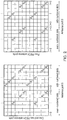
- the UE produces channel impulse responses of the form shown in Figure 5 .
- the accuracy with which the channel impulse response can be resolved in the time domain is shown to be a function of the sampling rate of the system.
- the accuracy of the determined channel impulse responses is compromised compared to systems operating at higher sample rates. This is primarily because by sampling at a low rate, the UE is more likely to miss the peak amplitude of the channel impulse response and it is the peak amplitude which is one mechanism to identify the distance to the eNB sending the PRS.
- there are other methods of determining the distance to the eNB such as determining the time location of the first path in the channel impulse response that is greater than a threshold.
- FIG. 5 This is shown diagrammatically in Figure 5 , where a UE with a basic sample time T s is shown in graph 1, a UE with a sample time of 2T s is shown in graph 2 and a UE with a sample time of T s /2 is shown in graph 3.
- Figure 6 provides a schematic diagram of a mobile telecommunications system 600, where the system includes mobile communications terminals 601, infrastructure equipment 602 and a core network 603.
- the core network 603 will include the positioning server.
- the infrastructure equipment may also be referred to as a base station, network element, enhanced Node B (eNodeB) or a coordinating entity for example, and provides a wireless access interface to the one or more communications terminals within a coverage area or cell.
- the one or more mobile communications terminals may communicate data via the transmission and reception of signals representing data using the wireless access interface.
- the network entity 602 is communicatively linked to core network components such as a serving gateway support node 603.1, a packet data gateway 603.2, a mobility management entity 603.3, and an external network 603.4, which may be connected to one or more other communications systems or networks which have a similar structure to that formed from communications terminals 601 and infrastructure equipment 602.
- Infrastructure equipment 602 (sometimes called an eNB) includes a transmitter 602.1, a receiver 602.2, a memory 602.3 and a controller 602.4.
- the transmitter 602.1 is configured to periodically send the PRS signal (or any type of signal that provides a position reference) to the mobile communication terminal 601. The timing of the transmission is controlled by the controller 602.4.
- the core network may also provide functionality including authentication, mobility management, charging and so on for the communications terminals served by the network entity.
- the mobile communications terminals of Figure 6 may also be referred to as communications terminals, user equipment (UE), terminal devices and so forth, and are configured to communicate with one or more other communications terminals served by the same or a different coverage area via the network entity.
- These mobile communications terminals (sometimes called UEs) 601 each include a transmitter 601.1, a receiver 601.2, a memory 601.3 and a controller 601.4.
- These communications may be performed by transmitting and receiving signals representing data using the wireless access interface over the two way communications links represented by lines 604 to 609, where 604, 606 and 608 represent downlink communications from the network entity to the communications terminals and 605, 607 and 609 represent the uplink communications from the communications terminals to the network entity.
- the PRS signal will be sent in the downlink signal.
- the UE 601 transmits an indication (for example, capability signalling) to the eNB 602. From the type of UE, the eNB 602 knows the sample rate at which the UE 601 samples the PRS signal. For example, for capability signalling indicating that the UE is an MTC type device, the sampling rate is a function of its system bandwidth. Therefore, as the network knows the type of UE, the sampling rate would be known to the network. That is, the capability signalling indicates to the eNB the sampling rate and sampling time of the UE. This will be appreciated by the skilled person.
- the communications system 600 may operate in accordance with any known protocol, for instance in some examples the system 600 may operate in accordance with a 3GPP Long Term Evolution (LTE) standard where the network entity and communications terminals are commonly referred to as eNodeB and UEs, respectively.
- LTE Long Term Evolution
- embodiments of the disclosure provide that the UE 601 samples the PRS at a low sample rate across multiple subframes and the eNB adjusts the timing of the transmitted PRS signal with a finer granularity than the UE's known sampling rate. As the UE 601 is provided with information indicating when (i.e. in which subframes) the eNB 602 adjusts its timing, the UE thus builds a more accurate sampling of the channel impulse response using different copies of the received sample signal.
- the transmission timing adjustments of all the measured eNBs in the positioning set must be known. It is therefore desirable if these timing adjustments are synchronised. However, this is not a requirement of the disclosure as would be apparent.
- the eNB 602 may notify the UE 601 of the timing adjustments applied in the different subframes during configuration of the positioning parameters. Alternatively, these may be specified a priori (for example in LTE specifications). In other embodiments, it is possible that the UE 601 may have stored adjustment patterns within the memory 601.3 and the eNB 602 may simply indicate to the UE 601 which stored pattern to use.
- the controller 602.4 of the eNB 602 cyclically increases its timing adjustment. For example for a UE sample period of Ts, and for two timing adjustments, the timing of the PRS transmissions from the eNB 602 are:
- Figure 7 shows how the UE 601 samples the non-adjusted and timing-adjusted signals from the eNB 602 in order to create a composite channel impulse response with an effective sample period of Ts/2 (when the native sampling period of the UE is Ts).
- the channel impulse response sampled with a sample time Ts and with no time adjustment applied by the eNB 602 is shown.
- graph 2 the channel impulse response sampled at time Ts and with a time adjustment of Ts/2 applied by the eNB 602 is shown.
- graph 3 the channel impulse response of the combined sampled channel impulse response is shown.
- time adjustments may be applied.
- the effective sample time of the UE 601 will be Ts/3.
- the controller 602.4 in the eNB 602 determines the time adjustment and instructs the transmitter 602.1 to transmit the PRS with the correct time adjustment.
- an antenna 405A is provided which feeds the received PRS-carrying signal to an RF Front End 410A.
- the RF Front End 410A includes an amplifier module, a filter module, a downconverter module and a sampling module (not shown for clarity).
- an RF bandpass filter within the RF front end 410A has a bandwidth that scales with the effective sampling rate. For example:
- the bandwidth of the RF front end is variable (e.g. through the use of a switched filter bank or the use of tuneable components in a filter contained within the RF front end).
- the use of a variable RF front end bandwidth allows for accurate resolution of the channel impulse response during positioning measurement occasions while reducing received noise power during reception of downlink data signals. This preserves the sensitivity of the received DL data signals.
- the output from the RF Front End 410A is fed into an FFT module 415A.
- the FFT module 415A, channel estimation module 420A and the IFFT module 425A in Figure 8 are similar in construction and arrangement as the FFT module 415, and a single channel estimation module 420A-N and a single the IFFT module 425A-N described in Figure 4 . It should be noted that, although only a single channel estimation module 420A and IFFT module 425A are shown in Figure 8 , in reality, one of these will be provided for each eNB from which the UE will receive a PRS signal.
- the output from the IFFT module 425A in Figure 8 is fed into two buffers; Buffer A 450A and buffer B 455A.
- Buffer A 450A stores channel impulse response values for the "no adjustment" timing alignment of Figure 7 .
- Buffer B 455A stores channel impulse response values for the "retard (or more generally adjust) by Ts/2" timing alignment of Figure 7 .
- the output from Buffer A and Buffer B is fed into an interleave and combine module 460A.
- the interleave and combine module 460A takes samples of the channel impulse response from buffer A 450A and interleaves them, according to the appropriate timing, with samples from buffer B in order to create the "shifted and combined channel impulse response" shown in graph 3 of Figure 7 .
- the output of the interleave and combine module 460A is fed into an RSTD calculation module 430A.
- the RSTD calculation module 430A is the same as the RSTD calculation module 430 of Figure 4 .
- the known RSTD calculations are then performed based on these "shifted and combined channel impulse responses".
- RF Front End 410A will be part of the transmitter 601.1 and receiver 601.2 of the UE 601.
- the remaining modules within Figure 8 will be part of the controller 601.4 of the UE 601.
- Figure 8 shows the receive chain for calculating a time delay for a single eNB and in practice, there may be multiple receive chains (multiple receive chains are shown in Figure 4 ), one receive chain being applied to each eNB being measured.
- the eNB frequency hops the PRS as well as performing timing adjustments on the transmitted signal. This allows the low sampling rate UE 601 to effectively mimic the RSTD performance of a wider bandwidth UE 601. This is because the UE 601 creates the same number of time and frequency domain samples as a wider bandwidth UE.
- the eNB transmits differently time adjusted versions of the transmitted signal at a first frequency, then hops, and then transmits another set of differently time adjusted versions of the transmitted signal at a second frequency. To put it another way, the eNB transmits non-adjusted and adjusted subframes at a first hop and then transmits non-adjusted and adjusted subframes at a second hop. In the alternative, the eNB transmits non-adjusted subframes at the first hop and adjusted subframes at the second hop.
- another UE architecture 601B is shown.
- an antenna 405B is coupled to an RF front End 410B.
- the antenna 405B and the RF Front End 410B are the same as the antenna 405A and the RF front end 410A of Figure 8 and so will not be described in any more detail.
- the output of the RF Front End 410B is fed into a sample module 465B.
- the purpose of the sample module 465B is to sample and reorder samples that occur before the FFT function, as shown in Figure 9 .
- the sample module 465B provides the sampling function after the RF front end 410B.
- This sampling function could be an ADC (analogue to digital converter) sampling function, for example operating at 320kHz for an NB-loT system.
- the samples are fed to two buffers; buffer A 450B and buffer B 455B.
- the PRS signal having no adjustment are provided to buffer A 450B and the PRS signal having a Ts/2 adjustment is provided to buffer B 455B.
- the samples from the buffers are interleaved and combined in the interleave and combine module 460B to create a composite effectively oversampled signal. This allows the UE 601 to effectively oversample the received signal (before performing the FFT).
- the output of the interleave and combine module 460B is fed into an FFT module 415B.
- the output of the FFT module 415B is fed to a channel estimator 420B.
- the output of the channel estimator 420B is fed to an inverse fast Fourier Transform module 425B and the output of the IFFT module 425B is fed to an RSTD calculation module 430B.
- the functionality of the FFT module, channel estimator, IFFT module and the RSTD module is the same as that described with reference to Figure 8 and so will not be described further. However, as will be understood from the following, the effective sampling rate in the architecture of Figure 9 will be higher.
- the UE 601 performs an FFT and subsequent processing functions on the effectively oversampled PRS signal.
- the number of operations required on this effectively oversampled signal is greater than the number of operations required on the baseline signal.
- the present disclosure may be implemented on an architecture based on dedicated hardware which would iteratively process the increased number of samples. For example, consider an eMTC device that creates 128 samples within an OFDM symbol (and hence operates with a 128-point FFT).
- the UE 601 creates 128 samples on the non-adjusted signal and a further 128 samples of the time-adjusted signal, creating 256 samples overall.
- the UE 601 can then perform a 256 point FFT in order to create an over-sampled channel impulse response.
- the larger the number of dithering steps i.e. the larger the number of time adjustments performed on the PRS signal
- the finer the sampling granularity leading to a higher accuracy is subject to the radio channel being static during a cycle of different dithering steps.
- different sets of PRS are transmitted where each set has a different number of dithering steps.
- the UE is assigned to the set of PRS with a lower number of dithering steps.
- the UE is assigned to a set of PRS with a higher number of dithering steps.
- the greater the number of dithering steps the lower the maximum speed that the system can tolerate. This is because if the channel changes significantly between subframes, a channel impulse response from one subframe cannot be interleaved with the channel impulse response from another subframe. This problem can be alleviated by the system making a coarse estimation of UE speed (either within the UE or within the core network) and assigning an appropriate number of dithering steps to the UE.
- the controller 601.4 within the UE can measure whether the channel changes significantly between dithering steps and report based on an appropriate number of dithering steps. In this case, when the UE reports an RSTD measurement, it can also report the number of dithering steps over which that RSTD measurement was obtained.
- the PRS is expected to be repeated.
- a repetition can be performed where in the first X subframes, the PRS is not dithered and in the subsequent Y subframes the PRS is dithered by a predefined amount.
- the UE can therefore combine the repetitive samples in X batches or Y batches as appropriate. It should be appreciated that the repetition can be longer than 2X where the cycling between dithered PRS and non-dithered PRS are cycled throughout the repetition. For example if there are K repetitions the number of cycles is K/NX where N is the number of different dithering steps.
- the transmission of further position reference signals is dependent on the channel conditions (e.g. the receiver's SNR, being an indication of the required coverage enhancement for the UE).
- the eNB changes (adjusts) the timing of the PRS transmission signal.
- the UE 601 it is possible for the UE 601 to change the phasing of the sampling signal to achieve the same effect.
- a diagram showing such an arrangement of a UE according to this embodiment is shown in Figure 10 .
- the arrangement in Figure 10 is similar to the arrangement of Figure 9 .
- the common features and modules will not be described for brevity.
- the sample clock for the sample module 465B is generated using a clock generation module 1000.
- the provision of the clock generation module 1000 means that the eNB 602 does not need to perform any adjustment on the timing of the PRS signal.
- a UE may be implemented using a processor-based architecture where a CPU operates at a clock frequency of several hundreds of MHz while the received signal is sampled at a much lower rate. For example, 320kHz in the case of NB-IoT.
- a UE implementation has a clock management function that creates clocks of various frequencies and may also create clocks of various phases. Hence various phases of a sampling clock may be created by the UE for general operation.
- the UE 601 generates different sampling phases for the received signal. For example, during a first subframe, the UE uses a first sampling phase (phase A) and during a second subframe, the UE uses a second sampling phase (phase B). This first and second sampling phase is generated by the clock generation module 1000 of Figure 10 . The oversampled signal is then processed according to the architecture shown in Figure 8 or 9 .
- the output of the clock generation module 1000 would sample the received PRS signal in the sampling module within the RF front end 410A.
- the output of the IFFT 425A will then be selectively fed to each of buffer_A 450A and buffer_B 455A. That is, the output of the IFFT 425A generated from phase A will be fed to buffer_A 450A and the output of the IFFT 425A generated from phase B will be fed to buffer_B 455A.
- the output of the clock generation module 1000 would sample the received PRS signal in the sampling module 465B (which has been shown explicitly). The output of the sampling module 465B will then be selectively fed to each of buffer_A 450B and buffer_B 455B. That is, the output of the sampling module 465B generated from phase A will be fed to buffer_A 450B and the output of the sampling module 465B generated from phase B will be fed to buffer B 455B.
- a crystal oscillator 1003 provides an input to a clock management circuit 1002.
- An example oscillator may operate at a resonant frequency of 40.96MHz.
- the clock management circuit 1002 doubles this frequency (e.g. via a phase locked loop) to provide a clock for a CPU 1004 of the UE 601.
- the CPU 1004 of the UE 601 may be the controller 601.4.
- the clock management circuit 1002 also divides the crystal oscillator input to provide two clocks of 320kHz, f phaseA and f phaseB . Both of these clocks have a frequency of 320kHz and have a difference in phase of 180 degrees. It is these two clocks that may be used in the embodiments of Figures 8 and 9 to generate the phase A and phase B signals.
- One method of producing the two clocks is to invert the f phaseA signal (e.g. via an inverter) to produce the f phaseB clock.
- inverter e.g. via an inverter
- other methods of producing clocks of varying phases including methods to create multiple phases of the clock, are envisaged.
- the multiplexer chooses one of the two clocks f phaseA or f phaseB for different subframes, in order to sample the input signal at different times.
- the subsequent signal processing shown in this figure is the same as shown in Figure 9 .
- the UE-based implementation of the disclosure explained with reference to Figure 10 requires that the eNB 602 does not change the timing of its transmit signal for the duration over which the UE 601 creates the effective oversamples of the received signal. For example, if the UE 601 samples the signal with two clock phases during two consecutive subframes, the eNB 602 must not change the timing of the two subframes relative to one another.
- the UE 601 reports its capability, e.g. in terms of the number of clock phases (and hence subframes) it uses to derive RSTD measurements. This may be carried out when the UE sends an indication (for example capability signalling) message to the eNB.
- the eNB 602 can then:
- the UE 601 can report the number of clock phases it used to create the RSTD measurement in the message where the RSTD measurement is reported.
- FIG. 11 shows a flowchart 1100 explaining a process at an eNB according to embodiments.
- the process 1100 starts at 1105.
- the eNB receives the capability signal from the UE at step 1110.
- the capability signal provides an indication of the sample time used by the UE.
- the eNB therefore determines the time adjustment needed to be applied to the PRS based on the sample time in step 1115.
- the eNB transmits the PRS without time adjustment in a first subframe and with appropriate time adjustment in a second subframe. This is step 1120 and the process ends in step 1125.
- FIG 12 shows a flowchart 1200 explaining a process at a UE receiving a PRS from an eNB operating according to Figure 11 .
- the flowchart 1200 starts at step 1205.
- the UE transmits capability information to the eNB in step 1210.
- the first PRS signal which is non-time adjusted is received in step 1215.
- the second PRS signal which is time adjusted is received in step 1220.
- Sampled channel impulse responses (CIR) are created from the first and second PRS in step 1225. These channel impulse responses are interleaved and combined in step 1230.
- the time of provision of the combined signal is determined in step 1235 and the process ends in step 1240.
- FIG. 13 shows a flowchart 1300 explaining a process at a UE according to another embodiment.
- the process starts at step 1305.
- the PRS is received from the eNB in step 1310.
- the PRS signal is sampled using phase A and phase B clocks in step 1315.
- the samples created using the phase A clock and the samples created using the phase B clock are combined in step 1320.
- the time of provision of the combined signal is determined based on the channel impulse response of the combination in step 1325.
- the process ends in step 1330.
- the terminal may be embedded in the object (e.g. a vehicle may comprise a mobile terminal in which a SIM card can be inserted), may be associated or paired with the object (e.g. a terminal may set up a Bluetooth connection with a Bluetooth module of the vehicle) or may simply be placed in a position wherein it is travelling with the object without having any particular communicative connection with the object (e.g. in the pocket of a driver or passenger in a vehicle).
- steps discussed herein may be carried out in any suitable order.
- steps may be carried out in an order which differs from an order used in the examples discussed above or from an order used anywhere else for listing steps (e.g. in the claims), whenever possible or appropriate.
- steps may be carried out in a different order, or simultaneously or in the same order.
- transmitting information or a message to an element may involve sending one or more messages to the element and may involve sending part of the information separately from the rest of the information.
- the number of "messages" involved may also vary depending on the layer or granularity considered.
Description
- The present disclosure relates to infrastructure equipment, telecommunications devices and methods
- The "background" description provided herein is for the purpose of generally presenting the context of the disclosure. Work of the presently named inventors, to the extent it is described in this background section, as well as aspects of the description which may not otherwise qualify as prior art or may not form part of the state of the art at the time of filing, are neither expressly or impliedly admitted as prior art or state of the art against the present invention.
- Mobile (or wireless) telecommunication systems, such as those based on the Third Generation Project Partnership (3GPP) defined Universal Mobile Telecommunication System (UMTS) and Long Term Evolution (LTE) architecture, are able to support more sophisticated services than simple voice and messaging services offered by previous generations of mobile telecommunication systems. For example, with the improved radio interface and enhanced data rates provided by LTE systems, a user is able to enjoy high data rate applications such as video streaming and video conferencing on mobile communications devices that would previously only have been available via a fixed line data connection.
- The demand to deploy fourth generation networks is therefore strong and the coverage area of these networks, i.e. geographic locations where access to the networks is possible, is increasing rapidly and expected to continue to increase. However, although the coverage and capacity of fourth generation networks is expected to significantly exceed those of previous generations of communications networks, there are still limitations on network capacity and the geographical areas that can be served by such networks. These limitations may, for example, be particularly relevant in situations in which networks are experiencing high load and high-data rate communications between communications devices, or when communications between communications devices are required but the communications devices may not be within the coverage area of a network.
- The anticipated widespread deployment of third and fourth generation networks has led to the parallel development of a number of new infrastructure architectures involving a variety of classes of devices, of wireless access point units and of applications which may require different data rates, coverage areas or transmission powers. Although there are applications which require high data rates to support their operation, there are some applications in which high data rates are not required. Indeed there are some applications which are expected to be provided by more simple, less complicated communications devices such as those supporting machine type communications (MTC). Such devices are also expected to be low power devices having applications which tend to be low-throughput and high-latency, and may include a relatively inexpensive low complexity transmitter and receiver. Such devices may also be deployed in locations in which radio communications conditions can make transmission and reception of signals more difficult. MTC applications are typified by semi-autonomous or autonomous wireless communication devices (i.e. MTC devices) communicating small amounts of data on a relatively infrequent basis. Examples include so-called smart meters which, for example, are located in a customer's house and periodically transmit information back to a central MTC server data relating to the customers consumption of a utility such as gas, water, electricity and so on. Other examples may include relay nodes which provide assistance to local terminals communicating with a base station.
- 3GPP has completed two Rel-13 Work Items on Internet of Things (loT) namely, eMTC (Enhanced Machine Type Communications) and NB-loT (Narrowband Internet of Things). These Work Items aimed at creating low cost devices that are power efficient and can operate in extended coverage e.g. such as inside basements.
- In Rel-14, 3GPP agreed to enhance these types of loT devices thereby introducing two Work Items namely, Rel-14 eNB-IoT (enhanced NB-IoT) [1] and Rel-14 fe-MTC (Further Enhanced MTC) [2]. One of the common objectives in these two WIs is positioning, which allows loT devices to be tracked.
- One of the positioning techniques considered for loT (i.e. eNB-IoT and fe-MTC) is Observed Time Difference Of Arrival (OTDOA), where the User Equipment (UE), which may be an loT device, an MTC device, or any kind of terminal device, measures the Reference Signal Time Difference (RSTD), i.e. the observed time difference between a target enhanced Node B (eNB) and a reference eNB. This is illustrated in
Figure 1 . The UE 100 measures RSTD for two or more eNBs (i.e. involving 3 or more eNBs since one of them is the reference eNB) and sends these measurements to aLocation Server 110 which is part of the core network. So, in the context ofFigure 1 , the reference eNB iseNB1 105A, and the two or more eNBs areeNB2 105B andeNB3 105C. TheLocation Server 110 calculates the UE 100 position based on these RSTD measurements using the known location of the eNBs involved. That is, the Location Server performs a triangulation (involving at least 3 eNBs) to determine the UE location as shown inFigure 1 . - The accuracy of the
UE 100 position is dependent upon the accuracy of the measured RSTD. For example, inFigure 1 , the time of arrival from eNB1 has an accuracy of ΔT1, the time of arrival of eNB2 has an accuracy of ΔT2 and the time of arrival for eNB3 has an accuracy of Δ T3. The accuracy of the time of arrival measurement is dependent upon the quality of the measured Reference Signal and the bandwidth of the Reference Signal. - The time of arrival can be estimated using a known signal, i.e. Reference Signals such as Cell-Specific Reference Signals (CRS), Primary Synchronisation Signals (PSS) or Secondary Synchronisation Signals (SSS). However, these reference signals (more generally "RS") experience inter-cell interferences and hence in LTE Rel-9, Positioning Reference Signals (PRS) were introduced.
-
Figure 2 shows the RE (Resource Element) location of a set of PRS for an eNB within a Physical Resource Block (PRB) and the location occupied is dependent upon the eNB's Cell ID. Up to 6 different sets of PRS locations with different frequency shifts can be transmitted, hence up to 6 different eNBs can be measured at a time (assuming one eNB per frequency shift). It should be noted that the eNBs sharing the same frequency shift would have different sequences to distinguish among themselves. The PRS is transmitted over NPRS={1, 2, 4, 6} consecutive subframes with a period of TPRS={160, 320, 640, 1280} subframes. The NPRS consecutive subframes of PRS transmission is known as the Positioning Occasion. An example of the Positioning Occasion and the period TPRS are shown inFigure 3 , where the Positioning Occasion has length NPRS=4 subframes andoccupies subframe - NB-loT and eMTC devices are low complexity devices. One route to achieving low complexity is to operate with a narrow bandwidth and a low sampling rate. However, the low sampling rate reduces the accuracy with which the position of a UE can be determined. The relationship between distance error, εd, and time error, εT, for a position derived from an RSTD measurement is (where 'c' is the speed of light):

- For a sampled signal, the time error is related to the sampling time. eMTC is a 1.4MHz bandwidth system and a UE typically uses a sampling rate of 1.92MHz (sample time = 0.52µs). NB-loT is a 180kHz bandwidth system with a typical sampling rate of 320kHz. Hence the position inaccuracy of these systems, due to the sampling rate, are:
- eMTC: εd = 156m
- NB-IoT: εT = 937m
- There are several possible implementations for deriving an RSTD measurement from a received signal, including correlation based techniques and techniques that create a time-domain channel impulse response.
-
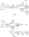
Figure 4 shows anexample architecture 400 of a UE that creates a time domain channel impulse response in order to derive RSTD measurements. Based on the channel impulse response produced by the IFFT functions, the UE can estimate the arrival times, TeNB1, TeNB2, ... TeNB6 of the signals from each eNB in the positioning set. RSTD measurements may then be derived based on these arrival time estimates. - In the
example architecture 400 ofFigure 4 , the PRS is received byantenna 405. The received signal is fed into a Radio FrequencyFront End module 410. This amplifies, filters, downconverts and samples the received signal as would be appreciated by the skilled person. The sampled signal is fed into a Fast Fourier Transform (FFT)module 415. This produces a frequency domain representation of the received waveform from which the PRS signal can be extracted, as would be appreciated by a skilled person. The PRS signal from the output of theFFT module 415 is fed to an array of channel estimator modules (420A...420N). In this discussion of the known system, there are six channel estimator modules in the array (one for each of the six eNBs whose PRS can be measured). Of course, any number is envisaged. - Referring back to
Figure 4 , the output of each of thechannel estimator modules 420A...420N is fed into an Inverse Fast Fourier Transform (IFFT)module 425A...425N. Each of these IFFT modules produces a channel impulse response for that particular eNB in the time domain. An example output of one of theIFFT modules 425A is shown inFigure 5 as will be explained later. These channel impulse responses are provided to anRSTD calculation module 430 which calculates the RSTD for each eNB using a known technique and sends these calculations to the Positioning Server which determine the position of the UE. - In the architecture of
Figure 4 , the UE produces channel impulse responses of the form shown inFigure 5 . The accuracy with which the channel impulse response can be resolved in the time domain is shown to be a function of the sampling rate of the system. For low sample rate systems, such as eMTC and NB-IoT, the accuracy of the determined channel impulse responses is compromised compared to systems operating at higher sample rates. This is primarily because by sampling at a low rate, the UE is more likely to miss the peak amplitude of the channel impulse response and it is the peak amplitude which is one mechanism to identify the distance to the eNB sending the PRS. Of course, and as would be appreciated, there are other methods of determining the distance to the eNB such as determining the time location of the first path in the channel impulse response that is greater than a threshold. - This is shown diagrammatically in
Figure 5 , where a UE with a basic sample time Ts is shown ingraph 1, a UE with a sample time of 2Ts is shown ingraph 2 and a UE with a sample time of Ts/2 is shown ingraph 3. - However, it is undesirable to increase the sample rate within the UE (especially eMTC and NB-loT type devices) because this increases the battery consumption and the complexity of the device. Therefore, it is desirable to improve the accuracy of positioning for eMTC and NB-loT, without increasing device complexity (i.e. without increasing the sampling rate of the device).
- It is an aim of the present disclosure to address this issue.
- Other prior art is disclosed in
US 2011/274220A ,US 6,573,761 B andEP 0 757 463AUS 2011/274220 A1 (ANDGART NIKLAS [SE] ET AL) 10 November 2011 (2011-11-10) discloses that PRS are transmitted during designated positioning occasions occurring typically once every 160-1280 subframes. - Various aspects and features of the present technique are defined in the appended claims.
- The foregoing paragraphs have been provided by way of general introduction, and are not intended to limit the scope of the following claims. The described embodiments, together with further advantages, will be best understood by reference to the following detailed description taken in conjunction with the accompanying drawings.
- A more complete appreciation of the disclosure and many of the attendant advantages thereof will be readily obtained as the same becomes better understood by reference to the following detailed description when considered in connection with the accompanying drawings wherein like reference numerals designate identical or corresponding parts, and wherein:
-
Figure 1 shows a schematic explaining positioning of a UE using triangulation; -
Figure 2 shows a schematic explaining the position of a PRS signal in a PRB; -
Figure 3 shows a schematic explaining the positioning occasion and period; -
Figure 4 shows a block diagram of a UE architecture for RSTD measurement based on time domain channel impulse response; -
Figure 5 shows an output of an Inverse Fast Fourier Transform module which shows amplitude as a function of time; -
Figure 6 provides a schematic diagram of a mobile communications system; -
Figure 7 shows a shifted and also combined channel impulse response according to embodiments; -
Figure 8 shows a UE architecture according to embodiments; -
Figure 9 shows another UE architecture according to embodiments; -
Figure 10 shows another UE architecture according to embodiments; -
Figure 11 shows a flowchart explaining a process at an eNB according to embodiments; -
Figure 12 shows a flowchart explaining a process at a UE according to embodiments; and -
Figure 13 shows a flowchart explaining a process at a UE according to other embodiments - Hereinafter preferred embodiments of the present technique will be described in detail with reference to the appended drawings. Note that, in this specification and appended drawings, structural elements that have substantially the same function and structure can be denoted with the same reference numerals, and repeated explanation of these structural elements may be omitted.
-
Figure 6 provides a schematic diagram of a mobile telecommunications system 600, where the system includesmobile communications terminals 601,infrastructure equipment 602 and acore network 603. In this example embodiment, thecore network 603 will include the positioning server. The infrastructure equipment may also be referred to as a base station, network element, enhanced Node B (eNodeB) or a coordinating entity for example, and provides a wireless access interface to the one or more communications terminals within a coverage area or cell. The one or more mobile communications terminals may communicate data via the transmission and reception of signals representing data using the wireless access interface. Thenetwork entity 602 is communicatively linked to core network components such as a serving gateway support node 603.1, a packet data gateway 603.2, a mobility management entity 603.3, and an external network 603.4, which may be connected to one or more other communications systems or networks which have a similar structure to that formed fromcommunications terminals 601 andinfrastructure equipment 602. Infrastructure equipment 602 (sometimes called an eNB) includes a transmitter 602.1, a receiver 602.2, a memory 602.3 and a controller 602.4. The transmitter 602.1 is configured to periodically send the PRS signal (or any type of signal that provides a position reference) to themobile communication terminal 601. The timing of the transmission is controlled by the controller 602.4. - The core network may also provide functionality including authentication, mobility management, charging and so on for the communications terminals served by the network entity. The mobile communications terminals of
Figure 6 may also be referred to as communications terminals, user equipment (UE), terminal devices and so forth, and are configured to communicate with one or more other communications terminals served by the same or a different coverage area via the network entity. These mobile communications terminals (sometimes called UEs) 601 each include a transmitter 601.1, a receiver 601.2, a memory 601.3 and a controller 601.4. These communications may be performed by transmitting and receiving signals representing data using the wireless access interface over the two way communications links represented bylines 604 to 609, where 604, 606 and 608 represent downlink communications from the network entity to the communications terminals and 605, 607 and 609 represent the uplink communications from the communications terminals to the network entity. The PRS signal will be sent in the downlink signal. Additionally, as would be appreciated, theUE 601 transmits an indication (for example, capability signalling) to theeNB 602. From the type of UE, theeNB 602 knows the sample rate at which theUE 601 samples the PRS signal. For example, for capability signalling indicating that the UE is an MTC type device, the sampling rate is a function of its system bandwidth. Therefore, as the network knows the type of UE, the sampling rate would be known to the network. That is, the capability signalling indicates to the eNB the sampling rate and sampling time of the UE. This will be appreciated by the skilled person. - The communications system 600 may operate in accordance with any known protocol, for instance in some examples the system 600 may operate in accordance with a 3GPP Long Term Evolution (LTE) standard where the network entity and communications terminals are commonly referred to as eNodeB and UEs, respectively.
- In a broad sense, embodiments of the disclosure provide that the
UE 601 samples the PRS at a low sample rate across multiple subframes and the eNB adjusts the timing of the transmitted PRS signal with a finer granularity than the UE's known sampling rate. As theUE 601 is provided with information indicating when (i.e. in which subframes) theeNB 602 adjusts its timing, the UE thus builds a more accurate sampling of the channel impulse response using different copies of the received sample signal. - The transmission timing adjustments of all the measured eNBs in the positioning set must be known. It is therefore desirable if these timing adjustments are synchronised. However, this is not a requirement of the disclosure as would be apparent.
- The
eNB 602 may notify theUE 601 of the timing adjustments applied in the different subframes during configuration of the positioning parameters. Alternatively, these may be specified a priori (for example in LTE specifications). In other embodiments, it is possible that theUE 601 may have stored adjustment patterns within the memory 601.3 and theeNB 602 may simply indicate to theUE 601 which stored pattern to use. - In one implementation, the controller 602.4 of the
eNB 602 cyclically increases its timing adjustment. For example for a UE sample period of Ts, and for two timing adjustments, the timing of the PRS transmissions from theeNB 602 are: - Subframe n: no adjustment
- Subframe n+1: retard the PRS by Ts/2
- Subframe n+2: no adjustment
-
Figure 7 shows how theUE 601 samples the non-adjusted and timing-adjusted signals from theeNB 602 in order to create a composite channel impulse response with an effective sample period of Ts/2 (when the native sampling period of the UE is Ts). Ingraph 1 ofFigure 7 , the channel impulse response sampled with a sample time Ts and with no time adjustment applied by theeNB 602 is shown. Ingraph 2, the channel impulse response sampled at time Ts and with a time adjustment of Ts/2 applied by theeNB 602 is shown. Finally ingraph 3, the channel impulse response of the combined sampled channel impulse response is shown. It is evident fromgraph 3, that a finer granularity of RSTD measurement can be obtained from the shifted and combined channel impulse response shown since the effective sample time ofgraph 3 is Ts/2. In other words, by applying the time adjustment of the PRS at theeNB 602, the effective sample time is of theUE 601 is decreased. This improves the RSTD measurement. It should be noted here that in this case, the arrival time of a single eNB would effectively be the provision (for example, generation) of the combined signal. The RSTD would be calculated on the basis of at least three of these provisioned signals. - Although only a single time adjustment is applied, the skilled person would appreciate any number of time adjustments may be applied. For example, in the event that two time adjustments are applied (i.e. the
eNB 602 sends a PRS with no adjustment insubframe 1, a time adjustment of Ts/3 relative tosubframe 1 insubframe 2 and a further adjustment of Ts/3 relative tosubframe 2 in subframe 3), the effective sample time of theUE 601 will be Ts/3. As noted above, the controller 602.4 in theeNB 602 determines the time adjustment and instructs the transmitter 602.1 to transmit the PRS with the correct time adjustment. - An embodiment of a UE 101A according to an embodiment of the disclosure is described with reference to
Figure 8 . In the UE 101A, anantenna 405A is provided which feeds the received PRS-carrying signal to anRF Front End 410A. As would be appreciated, theRF Front End 410A includes an amplifier module, a filter module, a downconverter module and a sampling module (not shown for clarity). - In this embodiment of the disclosure, an RF bandpass filter within the RF
front end 410A has a bandwidth that scales with the effective sampling rate. For example: - With no timing adjustments, the bandwidth of the RF front end is Fbase
- When two timing adjustments are made (i.e. the effective sampling period is Ts/2, as shown in
Figure 7 ), the bandwidth of the RF front end is 2xFbase - By operation of the RF front-end at a higher bandwidth, more accurate resolution of the channel impulse response and hence more accurate RSTD measurement is provided.
- It is realised by the inventors that the cost impact from the use of an RF front end with a higher bandwidth is quite small compared with operating with a higher sampling rate. Hence this embodiment of the disclosure is attractive from a cost perspective.
- In an embodiment of the disclosure, the bandwidth of the RF front end is variable (e.g. through the use of a switched filter bank or the use of tuneable components in a filter contained within the RF front end). The use of a variable RF front end bandwidth allows for accurate resolution of the channel impulse response during positioning measurement occasions while reducing received noise power during reception of downlink data signals. This preserves the sensitivity of the received DL data signals.
- The output from the
RF Front End 410A is fed into anFFT module 415A. TheFFT module 415A,channel estimation module 420A and theIFFT module 425A inFigure 8 are similar in construction and arrangement as theFFT module 415, and a singlechannel estimation module 420A-N and a single theIFFT module 425A-N described inFigure 4 . It should be noted that, although only a singlechannel estimation module 420A andIFFT module 425A are shown inFigure 8 , in reality, one of these will be provided for each eNB from which the UE will receive a PRS signal. - The output from the
IFFT module 425A inFigure 8 is fed into two buffers; Buffer A 450A andbuffer B 455A. Buffer A 450A stores channel impulse response values for the "no adjustment" timing alignment ofFigure 7 .Buffer B 455A stores channel impulse response values for the "retard (or more generally adjust) by Ts/2" timing alignment ofFigure 7 . The output from Buffer A and Buffer B is fed into an interleave and combinemodule 460A. The interleave and combinemodule 460A takes samples of the channel impulse response from buffer A 450A and interleaves them, according to the appropriate timing, with samples from buffer B in order to create the "shifted and combined channel impulse response" shown ingraph 3 ofFigure 7 . The output of the interleave and combinemodule 460A is fed into anRSTD calculation module 430A. TheRSTD calculation module 430A is the same as theRSTD calculation module 430 ofFigure 4 . The known RSTD calculations are then performed based on these "shifted and combined channel impulse responses". - It is expected that the
RF Front End 410A will be part of the transmitter 601.1 and receiver 601.2 of theUE 601. The remaining modules withinFigure 8 will be part of the controller 601.4 of theUE 601. - As noted above, for the sake of simplicity,
Figure 8 shows the receive chain for calculating a time delay for a single eNB and in practice, there may be multiple receive chains (multiple receive chains are shown inFigure 4 ), one receive chain being applied to each eNB being measured. - In embodiments of the disclosure, the eNB frequency hops the PRS as well as performing timing adjustments on the transmitted signal. This allows the low
sampling rate UE 601 to effectively mimic the RSTD performance of awider bandwidth UE 601. This is because theUE 601 creates the same number of time and frequency domain samples as a wider bandwidth UE. In an embodiment, the eNB transmits differently time adjusted versions of the transmitted signal at a first frequency, then hops, and then transmits another set of differently time adjusted versions of the transmitted signal at a second frequency. To put it another way, the eNB transmits non-adjusted and adjusted subframes at a first hop and then transmits non-adjusted and adjusted subframes at a second hop. In the alternative, the eNB transmits non-adjusted subframes at the first hop and adjusted subframes at the second hop. - In embodiments of the disclosure, another
UE architecture 601B is shown. In theUE architecture 601B ofFigure 9 , anantenna 405B is coupled to anRF front End 410B. Theantenna 405B and theRF Front End 410B are the same as theantenna 405A and the RFfront end 410A ofFigure 8 and so will not be described in any more detail. - The output of the
RF Front End 410B is fed into a sample module 465B.The purpose of thesample module 465B is to sample and reorder samples that occur before the FFT function, as shown inFigure 9 . As noted above, thesample module 465B provides the sampling function after the RFfront end 410B. This sampling function could be an ADC (analogue to digital converter) sampling function, for example operating at 320kHz for an NB-loT system. The samples are fed to two buffers; buffer A 450B andbuffer B 455B. In a similar manner to the disclosure ofFigure 8 , the PRS signal having no adjustment are provided to buffer A 450B and the PRS signal having a Ts/2 adjustment is provided to bufferB 455B. When all phases of the received signal (e.g. "no adjustment" and "retard (adjust) by Ts/2") have been sampled, the samples from the buffers are interleaved and combined in the interleave and combinemodule 460B to create a composite effectively oversampled signal. This allows theUE 601 to effectively oversample the received signal (before performing the FFT). - The output of the interleave and combine
module 460B is fed into anFFT module 415B. The output of theFFT module 415B is fed to achannel estimator 420B. The output of thechannel estimator 420B is fed to an inverse fastFourier Transform module 425B and the output of theIFFT module 425B is fed to anRSTD calculation module 430B. The functionality of the FFT module, channel estimator, IFFT module and the RSTD module is the same as that described with reference toFigure 8 and so will not be described further. However, as will be understood from the following, the effective sampling rate in the architecture ofFigure 9 will be higher. - With this arrangement, the
UE 601 performs an FFT and subsequent processing functions on the effectively oversampled PRS signal. Note that the number of operations required on this effectively oversampled signal is greater than the number of operations required on the baseline signal. However it is realised that this is not a problem since the samples can be processed in non-real time in a processor-based architecture. Moreover, the present disclosure may be implemented on an architecture based on dedicated hardware which would iteratively process the increased number of samples. For example, consider an eMTC device that creates 128 samples within an OFDM symbol (and hence operates with a 128-point FFT). In this case, theUE 601 creates 128 samples on the non-adjusted signal and a further 128 samples of the time-adjusted signal, creating 256 samples overall. TheUE 601 can then perform a 256 point FFT in order to create an over-sampled channel impulse response. - As noted above, the larger the number of dithering steps (i.e. the larger the number of time adjustments performed on the PRS signal), the finer the sampling granularity leading to a higher accuracy. However, this is subject to the radio channel being static during a cycle of different dithering steps.
- Therefore in another embodiment, different sets of PRS are transmitted where each set has a different number of dithering steps. For a UE with fast changing radio conditions, the UE is assigned to the set of PRS with a lower number of dithering steps. Conversely, for a UE with slowly changing radio conditions, the UE is assigned to a set of PRS with a higher number of dithering steps.
- Further, the greater the number of dithering steps, the lower the maximum speed that the system can tolerate. This is because if the channel changes significantly between subframes, a channel impulse response from one subframe cannot be interleaved with the channel impulse response from another subframe. This problem can be alleviated by the system making a coarse estimation of UE speed (either within the UE or within the core network) and assigning an appropriate number of dithering steps to the UE.
- Alternatively, the controller 601.4 within the UE can measure whether the channel changes significantly between dithering steps and report based on an appropriate number of dithering steps. In this case, when the UE reports an RSTD measurement, it can also report the number of dithering steps over which that RSTD measurement was obtained.
- IoT devices like eNB-IoT and feMTC are expected to operate in enhanced coverage. Under such operation, the PRS is expected to be repeated. Hence, in another embodiment, a repetition can be performed where in the first X subframes, the PRS is not dithered and in the subsequent Y subframes the PRS is dithered by a predefined amount. The UE can therefore combine the repetitive samples in X batches or Y batches as appropriate. It should be appreciated that the repetition can be longer than 2X where the cycling between dithered PRS and non-dithered PRS are cycled throughout the repetition. For example if there are K repetitions the number of cycles is K/NX where N is the number of different dithering steps. Hence the transmission of further position reference signals is dependent on the channel conditions (e.g. the receiver's SNR, being an indication of the required coverage enhancement for the UE).
- In the above, the eNB changes (adjusts) the timing of the PRS transmission signal. However, it is possible for the
UE 601 to change the phasing of the sampling signal to achieve the same effect. A diagram showing such an arrangement of a UE according to this embodiment is shown inFigure 10 . - As will be appreciated, the arrangement in
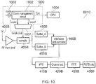
Figure 10 is similar to the arrangement ofFigure 9 . The common features and modules will not be described for brevity. However, in theUE 601C ofFigure 10 , the sample clock for thesample module 465B is generated using aclock generation module 1000. The provision of theclock generation module 1000 means that theeNB 602 does not need to perform any adjustment on the timing of the PRS signal. - In overview, the inventors have realised that many UE implementations use a higher system clock frequency than the sampling frequency of the PRS. For example, a UE may be implemented using a processor-based architecture where a CPU operates at a clock frequency of several hundreds of MHz while the received signal is sampled at a much lower rate. For example, 320kHz in the case of NB-IoT. Such a UE implementation has a clock management function that creates clocks of various frequencies and may also create clocks of various phases. Hence various phases of a sampling clock may be created by the UE for general operation.
- This is the basis for the UE based implementation. The
UE 601 according to embodiments, generates different sampling phases for the received signal. For example, during a first subframe, the UE uses a first sampling phase (phase A) and during a second subframe, the UE uses a second sampling phase (phase B). This first and second sampling phase is generated by theclock generation module 1000 ofFigure 10 . The oversampled signal is then processed according to the architecture shown inFigure 8 or 9 . - Specifically, in the system of
Figure 8 , the output of theclock generation module 1000 would sample the received PRS signal in the sampling module within the RFfront end 410A. The output of theIFFT 425A will then be selectively fed to each ofbuffer_A 450A andbuffer_B 455A. That is, the output of theIFFT 425A generated from phase A will be fed tobuffer_A 450A and the output of theIFFT 425A generated from phase B will be fed tobuffer_B 455A. - In
Figure 9 , the output of theclock generation module 1000 would sample the received PRS signal in thesampling module 465B (which has been shown explicitly). The output of thesampling module 465B will then be selectively fed to each ofbuffer_A 450B andbuffer_B 455B. That is, the output of thesampling module 465B generated from phase A will be fed tobuffer_A 450B and the output of thesampling module 465B generated from phase B will be fed to bufferB 455B. - The
clock generation module 1000 will now be described with reference toFigure 10 . In theclock generation module 1000 ofFigure 10 , acrystal oscillator 1003 provides an input to aclock management circuit 1002. An example oscillator may operate at a resonant frequency of 40.96MHz. Theclock management circuit 1002 doubles this frequency (e.g. via a phase locked loop) to provide a clock for aCPU 1004 of theUE 601. TheCPU 1004 of theUE 601 may be the controller 601.4. The clock frequency of theCPU 1004 operates at a frequency of fCPU = 81.92MHz. Theclock management circuit 1002 also divides the crystal oscillator input to provide two clocks of 320kHz, fphaseA and fphaseB. Both of these clocks have a frequency of 320kHz and have a difference in phase of 180 degrees. It is these two clocks that may be used in the embodiments ofFigures 8 and 9 to generate the phase A and phase B signals. - One method of producing the two clocks is to invert the fphaseA signal (e.g. via an inverter) to produce the fphaseB clock. Of course, other methods of producing clocks of varying phases, including methods to create multiple phases of the clock, are envisaged.
- The multiplexer chooses one of the two clocks fphaseA or fphaseB for different subframes, in order to sample the input signal at different times. The subsequent signal processing shown in this figure is the same as shown in
Figure 9 . - The UE-based implementation of the disclosure explained with reference to
Figure 10 requires that theeNB 602 does not change the timing of its transmit signal for the duration over which theUE 601 creates the effective oversamples of the received signal. For example, if theUE 601 samples the signal with two clock phases during two consecutive subframes, theeNB 602 must not change the timing of the two subframes relative to one another. - In an embodiment, the
UE 601 reports its capability, e.g. in terms of the number of clock phases (and hence subframes) it uses to derive RSTD measurements. This may be carried out when the UE sends an indication (for example capability signalling) message to the eNB. TheeNB 602 can then: - Transmit the signal appropriately to the UE. For example, maintaining timing for the appropriate number of subframes
- Determine the accuracy of the RSTD measurement reports from the
UE 601. For example, if theeNB 602 is told that theUE 601 use two clock phases to sample the signal, it estimates that the UE's RSTD measurement accuracy is twice that of a UE that samples the signal with a single phase. - Alternatively, the
UE 601 can report the number of clock phases it used to create the RSTD measurement in the message where the RSTD measurement is reported. -
Figure 11 shows aflowchart 1100 explaining a process at an eNB according to embodiments. Theprocess 1100 starts at 1105. The eNB then receives the capability signal from the UE atstep 1110. The capability signal provides an indication of the sample time used by the UE. The eNB therefore determines the time adjustment needed to be applied to the PRS based on the sample time in step 1115. The eNB then transmits the PRS without time adjustment in a first subframe and with appropriate time adjustment in a second subframe. This isstep 1120 and the process ends instep 1125. -
Figure 12 shows aflowchart 1200 explaining a process at a UE receiving a PRS from an eNB operating according toFigure 11 . Theflowchart 1200 starts atstep 1205. The UE transmits capability information to the eNB in step 1210. The first PRS signal which is non-time adjusted is received instep 1215. The second PRS signal which is time adjusted is received instep 1220. Sampled channel impulse responses (CIR) are created from the first and second PRS instep 1225. These channel impulse responses are interleaved and combined instep 1230. The time of provision of the combined signal is determined instep 1235 and the process ends instep 1240. -
Figure 13 shows aflowchart 1300 explaining a process at a UE according to another embodiment. The process starts atstep 1305. The PRS is received from the eNB instep 1310. The PRS signal is sampled using phase A and phase B clocks instep 1315. The samples created using the phase A clock and the samples created using the phase B clock are combined in step 1320. The time of provision of the combined signal is determined based on the channel impulse response of the combination in step 1325. The process ends instep 1330. - Although many of the examples above have been illustrated with a simple user equipment, the same teachings apply to a terminal which is not associated with any particular object or person, or associated with a pedestrian, a vehicle, a bicycle, a building or any other suitable object or person. In the case of an object, the terminal may be embedded in the object (e.g. a vehicle may comprise a mobile terminal in which a SIM card can be inserted), may be associated or paired with the object (e.g. a terminal may set up a Bluetooth connection with a Bluetooth module of the vehicle) or may simply be placed in a position wherein it is travelling with the object without having any particular communicative connection with the object (e.g. in the pocket of a driver or passenger in a vehicle).
- Additionally, the method steps discussed herein may be carried out in any suitable order. For example, steps may be carried out in an order which differs from an order used in the examples discussed above or from an order used anywhere else for listing steps (e.g. in the claims), whenever possible or appropriate. Thus, in some cases, some steps may be carried out in a different order, or simultaneously or in the same order.
- As used herein, transmitting information or a message to an element may involve sending one or more messages to the element and may involve sending part of the information separately from the rest of the information. The number of "messages" involved may also vary depending on the layer or granularity considered.
- Also, whenever an aspect is disclosed in respect of an apparatus or system, the teachings are also disclosed for the corresponding method. Likewise, whenever an aspect is disclosed in respect of a method, the teachings are also disclosed for any suitable corresponding apparatus or system.
- Whenever the expressions "greater than" or "smaller than" or equivalent are used herein, it is intended that they disclose both alternatives "and equal to" and "and not equal to" unless one alternative is expressly excluded.
- It is noteworthy that even though the present disclosure has been discussed in the context of LTE, its teachings are applicable to but not limited to LTE or to other 3GPP standards. In particular, even though the terminology used herein is generally the same or similar to that of the LTE standards, the teachings are not limited to the present version of LTE and could apply equally to any appropriate arrangement not based on LTE and/or compliant with any other future version of an LTE or 3GPP or other standard.
- Various further aspects and features of the present technique are defined in the appended claims. Various modifications may be made to the embodiments hereinbefore described within the scope of the appended claims. For example although LTE has been presented as an example application, it will be appreciated that other mobile communications systems can be used for which the present technique can be used.
-
- [1] RP-161324, "New work item proposal: Enhancements of NB-IoT," Vodafone, Huawei, HiSilicon, Ericsson, Qualcomm, RAN#72
- [2] RP-161321, "New WI proposal on Further Enhanced MTC", Ericsson, RAN#72
Claims (15)
- Infrastructure equipment (602) for transmitting data to and receiving data from a mobile device (601) on a communications network, the infrastructure equipment comprising:transmitter circuitry (602.1) configured to transmit the data to the mobile device; andcontroller circuitry (601.4) configured to control the transmitter circuitry (602.1) to transmit a first position reference signal in a first subframe and a second position reference signal in a second subframe, wherein the second position reference signal is a time adjusted version of the first position reference signal, the amount of time adjustment being determined by the sample time at which the mobile device samples the position reference signal.
- Infrastructure equipment according to claim 1, comprising receiver circuitry configured to receive data from the mobile device, and the controller is configured to control the receiver circuitry to receive capability signalling indicating the sample time from the mobile device.
- Infrastructure equipment according to claim 1, wherein the controller circuitry is configured to control the transmitter circuitry to frequency hop the first and second position reference signal.
- Infrastructure equipment according to claim 1, wherein the controller circuitry is configured to control the transmitter circuitry to transmit a plurality of further position reference signals, the time adjustment between each of the position reference signals being determined by the sample time and the number of position reference signals.
- Infrastructure equipment according to claim 4, wherein the controller circuitry is configured such that the number of further position reference signals is dependent upon channel conditions to the mobile device.
- Infrastructure equipment according to claim 4, wherein the controller circuitry is configured such that the number of further position reference signals is dependent upon the speed of the mobile device.
- A mobile device (601) for transmitting data to and receiving data from infrastructure equipment (602) according to claim 1, the mobile device comprising:receiver circuitry (601.2) configured to receive data from the infrastructure equipment (602); andcontroller circuitry (601.4) configured to:control the receiver circuitry (601.2) to receive the first position reference signal in the first subframe and the second position reference signal in the second subframe;sample a channel impulse response of the first position reference signal and a channel impulse response of the second position reference signal at the sampling rate;combine the sampled channel impulse response of the first position reference signal and the sampled channel impulse response of the second position reference signal to form a combined signal;anddetermine a time of provision of the combined signal based on the combination of the sampled channel impulse response of the first position reference signal and the sampled channel impulse response of the second position reference signal.
- A mobile device according to claim 7, wherein the receiver circuitry comprises a bandpass filter having a variable bandwidth.
- A mobile device according to claim 8, wherein the bandwidth scales in accordance with the sample rate.
- A mobile device according to claim 7, further wherein the controller circuitry is configured to store the sampled channel impulse response of the first position reference signal in a first buffer and to store the sampled channel impulse response of the second position reference signal in a second buffer and to produce the combined signal.
- A mobile device (601) for transmitting data to and receiving data from infrastructure equipment according to claim 1, the mobile device comprising:receiver circuitry (601.2) configured to receive data from the infrastructure equipment (602); andcontroller circuitry (601.4) configured to:control the receiver circuitry (601.2) to receive the first position reference signal in the first subframe and the second position reference signal in the second subframe;sample the received first position reference signal and the second position reference signal at the sample rate;store the sampled first position reference signal in a first buffer and the sampled second position reference signal in a second buffer;combine the sampled first position reference signal and the second position reference signal to form a combined signal; anddetermine a time of provision of the combined signal based on a channel impulse response of the combined signal.
- A method of operating infrastructure equipment for transmitting data to and receiving data from a mobile device on a communications network, the method comprising:
transmitting a first position reference signal in a first subframe and a second position reference signal in a second subframe, wherein the second position reference signal is a time adjusted version of the first position reference signal, the amount of time adjustment being determined by the sample time at which the mobile device samples the position reference signal. - A method according to claim 12, comprising receiving capability signalling indicating the sample time from the mobile device.
- A method according to claim 12, comprising frequency hopping the first and second position reference signal.
- A computer readable storage medium configured to store computer readable instructions which, when loaded onto a computer, configure the computer to perform a method according to any one of claim 12, 13 or 14.
Applications Claiming Priority (2)
| Application Number | Priority Date | Filing Date | Title |
|---|---|---|---|
| EP16183980 | 2016-08-12 | ||
| PCT/EP2017/070231 WO2018029269A1 (en) | 2016-08-12 | 2017-08-09 | Methods and apparatuses for communicating position reference signals |
Publications (2)
| Publication Number | Publication Date |
|---|---|
| EP3497864A1 EP3497864A1 (en) | 2019-06-19 |
| EP3497864B1 true EP3497864B1 (en) | 2020-09-30 |
Family
ID=56684517
Family Applications (1)
| Application Number | Title | Priority Date | Filing Date |
|---|---|---|---|
| EP17754311.3A Active EP3497864B1 (en) | 2016-08-12 | 2017-08-09 | Methods and apparatuses for communicating position reference signals |
Country Status (3)
| Country | Link |
|---|---|
| US (2) | US10966174B2 (en) |
| EP (1) | EP3497864B1 (en) |
| WO (1) | WO2018029269A1 (en) |
Families Citing this family (2)
| Publication number | Priority date | Publication date | Assignee | Title |
|---|---|---|---|---|
| WO2019083345A1 (en) * | 2017-10-27 | 2019-05-02 | 엘지전자 주식회사 | Method for performing otdoa-related operation by terminal in wireless communication system, and apparatus therefor |
| US11582584B2 (en) * | 2020-08-12 | 2023-02-14 | Shanghai Langbo Communication Technology Company Limiied | Method and device in communication nodes for wireless communication |
Family Cites Families (17)
| Publication number | Priority date | Publication date | Assignee | Title |
|---|---|---|---|---|
| US20010055320A1 (en) * | 1994-12-15 | 2001-12-27 | Pierzga Wayne Francis | Multiplex communication |
| US5862187A (en) * | 1995-07-31 | 1999-01-19 | Lucent Technologies Inc. | MPSK demodulator |
| US6573761B1 (en) * | 2002-04-08 | 2003-06-03 | Agilent Technologies, Inc. | Timebase for sampling an applied signal having a synchronous trigger |
| US7224721B2 (en) * | 2002-10-11 | 2007-05-29 | The Mitre Corporation | System for direct acquisition of received signals |
| US8311159B2 (en) * | 2009-01-09 | 2012-11-13 | Qualcomm Incorporated | Methods and systems for time tracking in OFDM systems |
| US8582698B2 (en) * | 2010-05-10 | 2013-11-12 | Telefonaktiebolaget Lm Ericsson (Publ) | Reduced complexity timing estimation for locating the position of a mobile terminal |
| WO2012156791A2 (en) * | 2011-05-16 | 2012-11-22 | Marvell World Trade Ltd. | Systems and methods for processing time-division signals and frequency-division signals |
| EP2777315A1 (en) * | 2011-11-07 | 2014-09-17 | Nokia Solutions and Networks Oy | Method and apparatus for receiving uplink signals |
| KR101948574B1 (en) * | 2012-03-12 | 2019-02-15 | 한국전자통신연구원 | Apparatus and method for preventing collision of vassels |
| US10863313B2 (en) * | 2014-08-01 | 2020-12-08 | Polte Corporation | Network architecture and methods for location services |
| US9497644B2 (en) * | 2012-10-01 | 2016-11-15 | Telefonaktiebolaget Lm Ericsson (Publ) | User equipment, network node and methods therein |
| WO2015180858A1 (en) * | 2014-05-28 | 2015-12-03 | Sony Corporation | Communications device, infrastructure equipment and methods for lte communication within unused gsm channels |
| US10136432B2 (en) * | 2015-04-10 | 2018-11-20 | Sony Corporation | Infrastructure equipment, communications device and methods |
| KR102597950B1 (en) * | 2016-03-30 | 2023-11-02 | 인터디지탈 패튼 홀딩스, 인크 | Reducing latency in physical channels in an lte network |
| US11122535B2 (en) * | 2016-07-15 | 2021-09-14 | Qualcomm Incorporated | Techniques for locating devices using narrowband positioning reference signals |
| CN109564726A (en) * | 2016-10-19 | 2019-04-02 | 华为技术有限公司 | A kind of localization method and mobile device |
| US10104624B2 (en) * | 2016-11-04 | 2018-10-16 | Qualcomm Incorporated | Techniques for adjusting transmit power in wireless communications |
-
2017
- 2017-08-09 WO PCT/EP2017/070231 patent/WO2018029269A1/en unknown
- 2017-08-09 US US16/323,265 patent/US10966174B2/en active Active
- 2017-08-09 EP EP17754311.3A patent/EP3497864B1/en active Active
-
2021
- 2021-03-29 US US17/215,579 patent/US11728943B2/en active Active
Non-Patent Citations (1)
| Title |
|---|
| None * |
Also Published As
| Publication number | Publication date |
|---|---|
| EP3497864A1 (en) | 2019-06-19 |
| WO2018029269A1 (en) | 2018-02-15 |
| US20210219258A1 (en) | 2021-07-15 |
| US10966174B2 (en) | 2021-03-30 |
| US11728943B2 (en) | 2023-08-15 |
| US20200196271A1 (en) | 2020-06-18 |
Similar Documents
| Publication | Publication Date | Title |
|---|---|---|
| EP3459315B1 (en) | Random access method for multiple numerology operation | |
| CN106972915B (en) | Signal transmission method and narrow-band wireless terminal | |
| JP6262849B2 (en) | Transmitter, receiver, and method for transmitting / receiving synchronization signals | |
| JP5809660B2 (en) | Wireless communication system and communication control method | |
| EP3668205A1 (en) | Positioning and measurement reporting method and apparatus | |
| JP6300165B2 (en) | COMMUNICATION DEVICE, REFERENCE SIGNAL RECEIVING METHOD, AND INTEGRATED CIRCUIT | |
| CN109565778B (en) | Mobile device, network node and method of determining a location of a mobile device | |
| RU2726172C1 (en) | Method and device for signal detection | |
| EP3700286B1 (en) | Data sending method, base station, and terminal device | |
| JP6250023B2 (en) | Bandwidth adaptive reference signal | |
| US11728943B2 (en) | Methods and apparatuses for communicating position reference signals | |
| GB2583691A (en) | Methods, apparatus, and systems for transmitting and receiving positioning reference signals in 5G new radio networks | |
| WO2017132806A1 (en) | Method for configuring pilot signal, and first device | |
| JP2010056740A (en) | Communication system, communication apparatus, communication control method, and communication control program | |
| EP2827660A1 (en) | Mobile terminal and base station | |
| JPWO2008096408A1 (en) | Wireless terminal device | |
| US11647536B2 (en) | Methods, device and computer-readable medium for determining timing advance | |
| CN102790636B (en) | Method for transmitting intelligent antenna calibration sequence | |
| KR100817015B1 (en) | Method and apparatus for tracking clock frequency in mb-ofdm system | |
| CN116686350A (en) | Uplink-based and downlink-based positioning | |
| JP6559763B2 (en) | Transmitter, receiver, and method for transmitting / receiving synchronization signals | |
| JPWO2011007414A1 (en) | Wireless communication system, base station, mobile station, and wireless communication method | |
| WO2016188273A1 (en) | Frequency offset estimation method and apparatus | |
| CN117796058A (en) | Time synchronization technique |
Legal Events
| Date | Code | Title | Description |
|---|---|---|---|
| STAA | Information on the status of an ep patent application or granted ep patent |
Free format text: STATUS: UNKNOWN |
|
| STAA | Information on the status of an ep patent application or granted ep patent |
Free format text: STATUS: THE INTERNATIONAL PUBLICATION HAS BEEN MADE |
|
| PUAI | Public reference made under article 153(3) epc to a published international application that has entered the european phase |
Free format text: ORIGINAL CODE: 0009012 |
|
| STAA | Information on the status of an ep patent application or granted ep patent |
Free format text: STATUS: REQUEST FOR EXAMINATION WAS MADE |
|
| 17P | Request for examination filed |
Effective date: 20190212 |
|
| AK | Designated contracting states |
Kind code of ref document: A1 Designated state(s): AL AT BE BG CH CY CZ DE DK EE ES FI FR GB GR HR HU IE IS IT LI LT LU LV MC MK MT NL NO PL PT RO RS SE SI SK SM TR |
|
| AX | Request for extension of the european patent |
Extension state: BA ME |
|
| DAV | Request for validation of the european patent (deleted) | ||
| DAX | Request for extension of the european patent (deleted) | ||
| GRAP | Despatch of communication of intention to grant a patent |
Free format text: ORIGINAL CODE: EPIDOSNIGR1 |
|
| STAA | Information on the status of an ep patent application or granted ep patent |
Free format text: STATUS: GRANT OF PATENT IS INTENDED |
|
| RIC1 | Information provided on ipc code assigned before grant |
Ipc: G01S 5/10 20060101ALI20200305BHEP Ipc: H04L 27/26 20060101ALI20200305BHEP Ipc: G01S 5/02 20100101ALI20200305BHEP Ipc: G01S 1/04 20060101ALI20200305BHEP Ipc: H04L 5/00 20060101AFI20200305BHEP Ipc: H04W 64/00 20090101ALN20200305BHEP |
|
| INTG | Intention to grant announced |
Effective date: 20200326 |
|
| RIC1 | Information provided on ipc code assigned before grant |
Ipc: G01S 1/04 20060101ALI20200317BHEP Ipc: H04L 27/26 20060101ALI20200317BHEP Ipc: H04W 64/00 20090101ALN20200317BHEP Ipc: G01S 5/10 20060101ALI20200317BHEP Ipc: G01S 5/02 20100101ALI20200317BHEP Ipc: H04L 5/00 20060101AFI20200317BHEP |
|
| GRAS | Grant fee paid |
Free format text: ORIGINAL CODE: EPIDOSNIGR3 |
|
| GRAA | (expected) grant |
Free format text: ORIGINAL CODE: 0009210 |
|
| STAA | Information on the status of an ep patent application or granted ep patent |
Free format text: STATUS: THE PATENT HAS BEEN GRANTED |
|
| AK | Designated contracting states |
Kind code of ref document: B1 Designated state(s): AL AT BE BG CH CY CZ DE DK EE ES FI FR GB GR HR HU IE IS IT LI LT LU LV MC MK MT NL NO PL PT RO RS SE SI SK SM TR |
|
| REG | Reference to a national code |
Ref country code: CH Ref legal event code: EP Ref country code: GB Ref legal event code: FG4D |
|
| REG | Reference to a national code |
Ref country code: AT Ref legal event code: REF Ref document number: 1319913 Country of ref document: AT Kind code of ref document: T Effective date: 20201015 |
|
| REG | Reference to a national code |
Ref country code: DE Ref legal event code: R096 Ref document number: 602017024655 Country of ref document: DE |
|
| REG | Reference to a national code |
Ref country code: IE Ref legal event code: FG4D |
|
| REG | Reference to a national code |
Ref country code: NL Ref legal event code: FP |
|
| PG25 | Lapsed in a contracting state [announced via postgrant information from national office to epo] |
Ref country code: GR Free format text: LAPSE BECAUSE OF FAILURE TO SUBMIT A TRANSLATION OF THE DESCRIPTION OR TO PAY THE FEE WITHIN THE PRESCRIBED TIME-LIMIT Effective date: 20201231 Ref country code: NO Free format text: LAPSE BECAUSE OF FAILURE TO SUBMIT A TRANSLATION OF THE DESCRIPTION OR TO PAY THE FEE WITHIN THE PRESCRIBED TIME-LIMIT Effective date: 20201230 Ref country code: HR Free format text: LAPSE BECAUSE OF FAILURE TO SUBMIT A TRANSLATION OF THE DESCRIPTION OR TO PAY THE FEE WITHIN THE PRESCRIBED TIME-LIMIT Effective date: 20200930 Ref country code: BG Free format text: LAPSE BECAUSE OF FAILURE TO SUBMIT A TRANSLATION OF THE DESCRIPTION OR TO PAY THE FEE WITHIN THE PRESCRIBED TIME-LIMIT Effective date: 20201230 Ref country code: FI Free format text: LAPSE BECAUSE OF FAILURE TO SUBMIT A TRANSLATION OF THE DESCRIPTION OR TO PAY THE FEE WITHIN THE PRESCRIBED TIME-LIMIT Effective date: 20200930 Ref country code: SE Free format text: LAPSE BECAUSE OF FAILURE TO SUBMIT A TRANSLATION OF THE DESCRIPTION OR TO PAY THE FEE WITHIN THE PRESCRIBED TIME-LIMIT Effective date: 20200930 |
|
| REG | Reference to a national code |
Ref country code: AT Ref legal event code: MK05 Ref document number: 1319913 Country of ref document: AT Kind code of ref document: T Effective date: 20200930 |
|
| PG25 | Lapsed in a contracting state [announced via postgrant information from national office to epo] |
Ref country code: LV Free format text: LAPSE BECAUSE OF FAILURE TO SUBMIT A TRANSLATION OF THE DESCRIPTION OR TO PAY THE FEE WITHIN THE PRESCRIBED TIME-LIMIT Effective date: 20200930 Ref country code: RS Free format text: LAPSE BECAUSE OF FAILURE TO SUBMIT A TRANSLATION OF THE DESCRIPTION OR TO PAY THE FEE WITHIN THE PRESCRIBED TIME-LIMIT Effective date: 20200930 |
|
| REG | Reference to a national code |
Ref country code: LT Ref legal event code: MG4D |
|
| PG25 | Lapsed in a contracting state [announced via postgrant information from national office to epo] |
Ref country code: EE Free format text: LAPSE BECAUSE OF FAILURE TO SUBMIT A TRANSLATION OF THE DESCRIPTION OR TO PAY THE FEE WITHIN THE PRESCRIBED TIME-LIMIT Effective date: 20200930 Ref country code: SM Free format text: LAPSE BECAUSE OF FAILURE TO SUBMIT A TRANSLATION OF THE DESCRIPTION OR TO PAY THE FEE WITHIN THE PRESCRIBED TIME-LIMIT Effective date: 20200930 Ref country code: RO Free format text: LAPSE BECAUSE OF FAILURE TO SUBMIT A TRANSLATION OF THE DESCRIPTION OR TO PAY THE FEE WITHIN THE PRESCRIBED TIME-LIMIT Effective date: 20200930 Ref country code: PT Free format text: LAPSE BECAUSE OF FAILURE TO SUBMIT A TRANSLATION OF THE DESCRIPTION OR TO PAY THE FEE WITHIN THE PRESCRIBED TIME-LIMIT Effective date: 20210201 Ref country code: CZ Free format text: LAPSE BECAUSE OF FAILURE TO SUBMIT A TRANSLATION OF THE DESCRIPTION OR TO PAY THE FEE WITHIN THE PRESCRIBED TIME-LIMIT Effective date: 20200930 Ref country code: LT Free format text: LAPSE BECAUSE OF FAILURE TO SUBMIT A TRANSLATION OF THE DESCRIPTION OR TO PAY THE FEE WITHIN THE PRESCRIBED TIME-LIMIT Effective date: 20200930 |
|
| PG25 | Lapsed in a contracting state [announced via postgrant information from national office to epo] |
Ref country code: ES Free format text: LAPSE BECAUSE OF FAILURE TO SUBMIT A TRANSLATION OF THE DESCRIPTION OR TO PAY THE FEE WITHIN THE PRESCRIBED TIME-LIMIT Effective date: 20200930 Ref country code: AT Free format text: LAPSE BECAUSE OF FAILURE TO SUBMIT A TRANSLATION OF THE DESCRIPTION OR TO PAY THE FEE WITHIN THE PRESCRIBED TIME-LIMIT Effective date: 20200930 Ref country code: AL Free format text: LAPSE BECAUSE OF FAILURE TO SUBMIT A TRANSLATION OF THE DESCRIPTION OR TO PAY THE FEE WITHIN THE PRESCRIBED TIME-LIMIT Effective date: 20200930 Ref country code: PL Free format text: LAPSE BECAUSE OF FAILURE TO SUBMIT A TRANSLATION OF THE DESCRIPTION OR TO PAY THE FEE WITHIN THE PRESCRIBED TIME-LIMIT Effective date: 20200930 Ref country code: IS Free format text: LAPSE BECAUSE OF FAILURE TO SUBMIT A TRANSLATION OF THE DESCRIPTION OR TO PAY THE FEE WITHIN THE PRESCRIBED TIME-LIMIT Effective date: 20210130 |
|
| PG25 | Lapsed in a contracting state [announced via postgrant information from national office to epo] |
Ref country code: SK Free format text: LAPSE BECAUSE OF FAILURE TO SUBMIT A TRANSLATION OF THE DESCRIPTION OR TO PAY THE FEE WITHIN THE PRESCRIBED TIME-LIMIT Effective date: 20200930 |
|
| REG | Reference to a national code |
Ref country code: DE Ref legal event code: R097 Ref document number: 602017024655 Country of ref document: DE |
|
| RAP4 | Party data changed (patent owner data changed or rights of a patent transferred) |
Owner name: SONY GROUP CORPORATION Owner name: SONY EUROPE LIMITED |
|
| PLBE | No opposition filed within time limit |
Free format text: ORIGINAL CODE: 0009261 |
|
| STAA | Information on the status of an ep patent application or granted ep patent |
Free format text: STATUS: NO OPPOSITION FILED WITHIN TIME LIMIT |
|
| PG25 | Lapsed in a contracting state [announced via postgrant information from national office to epo] |
Ref country code: DK Free format text: LAPSE BECAUSE OF FAILURE TO SUBMIT A TRANSLATION OF THE DESCRIPTION OR TO PAY THE FEE WITHIN THE PRESCRIBED TIME-LIMIT Effective date: 20200930 |
|
| 26N | No opposition filed |
Effective date: 20210701 |
|
| PG25 | Lapsed in a contracting state [announced via postgrant information from national office to epo] |
Ref country code: SI Free format text: LAPSE BECAUSE OF FAILURE TO SUBMIT A TRANSLATION OF THE DESCRIPTION OR TO PAY THE FEE WITHIN THE PRESCRIBED TIME-LIMIT Effective date: 20200930 |
|
| REG | Reference to a national code |
Ref country code: CH Ref legal event code: PL |
|
| PG25 | Lapsed in a contracting state [announced via postgrant information from national office to epo] |
Ref country code: MC Free format text: LAPSE BECAUSE OF FAILURE TO SUBMIT A TRANSLATION OF THE DESCRIPTION OR TO PAY THE FEE WITHIN THE PRESCRIBED TIME-LIMIT Effective date: 20200930 |
|
| REG | Reference to a national code |
Ref country code: BE Ref legal event code: MM Effective date: 20210831 |
|
| PG25 | Lapsed in a contracting state [announced via postgrant information from national office to epo] |
Ref country code: LI Free format text: LAPSE BECAUSE OF NON-PAYMENT OF DUE FEES Effective date: 20210831 Ref country code: CH Free format text: LAPSE BECAUSE OF NON-PAYMENT OF DUE FEES Effective date: 20210831 |
|
| PG25 | Lapsed in a contracting state [announced via postgrant information from national office to epo] |
Ref country code: IS Free format text: LAPSE BECAUSE OF FAILURE TO SUBMIT A TRANSLATION OF THE DESCRIPTION OR TO PAY THE FEE WITHIN THE PRESCRIBED TIME-LIMIT Effective date: 20210130 Ref country code: LU Free format text: LAPSE BECAUSE OF NON-PAYMENT OF DUE FEES Effective date: 20210809 |
|
| PG25 | Lapsed in a contracting state [announced via postgrant information from national office to epo] |
Ref country code: IE Free format text: LAPSE BECAUSE OF NON-PAYMENT OF DUE FEES Effective date: 20210809 Ref country code: BE Free format text: LAPSE BECAUSE OF NON-PAYMENT OF DUE FEES Effective date: 20210831 |
|
| PGFP | Annual fee paid to national office [announced via postgrant information from national office to epo] |
Ref country code: IT Payment date: 20220720 Year of fee payment: 6 |
|
| PG25 | Lapsed in a contracting state [announced via postgrant information from national office to epo] |
Ref country code: CY Free format text: LAPSE BECAUSE OF FAILURE TO SUBMIT A TRANSLATION OF THE DESCRIPTION OR TO PAY THE FEE WITHIN THE PRESCRIBED TIME-LIMIT Effective date: 20200930 |
|
| P01 | Opt-out of the competence of the unified patent court (upc) registered |
Effective date: 20230606 |
|
| PG25 | Lapsed in a contracting state [announced via postgrant information from national office to epo] |
Ref country code: HU Free format text: LAPSE BECAUSE OF FAILURE TO SUBMIT A TRANSLATION OF THE DESCRIPTION OR TO PAY THE FEE WITHIN THE PRESCRIBED TIME-LIMIT; INVALID AB INITIO Effective date: 20170809 |
|
| PGFP | Annual fee paid to national office [announced via postgrant information from national office to epo] |
Ref country code: NL Payment date: 20230721 Year of fee payment: 7 |
|
| PGFP | Annual fee paid to national office [announced via postgrant information from national office to epo] |
Ref country code: GB Payment date: 20230720 Year of fee payment: 7 |
|
| PGFP | Annual fee paid to national office [announced via postgrant information from national office to epo] |
Ref country code: FR Payment date: 20230720 Year of fee payment: 7 Ref country code: DE Payment date: 20230720 Year of fee payment: 7 |