EP3497377B1 - Temperature control system and methods for operating same - Google Patents
Temperature control system and methods for operating same Download PDFInfo
- Publication number
- EP3497377B1 EP3497377B1 EP16912865.9A EP16912865A EP3497377B1 EP 3497377 B1 EP3497377 B1 EP 3497377B1 EP 16912865 A EP16912865 A EP 16912865A EP 3497377 B1 EP3497377 B1 EP 3497377B1
- Authority
- EP
- European Patent Office
- Prior art keywords
- temperature
- monitored
- air temperature
- time
- air
- Prior art date
- Legal status (The legal status is an assumption and is not a legal conclusion. Google has not performed a legal analysis and makes no representation as to the accuracy of the status listed.)
- Active
Links
- 238000000034 method Methods 0.000 title claims description 58
- 239000003570 air Substances 0.000 claims description 222
- 238000001816 cooling Methods 0.000 claims description 118
- 238000009423 ventilation Methods 0.000 claims description 24
- 238000012544 monitoring process Methods 0.000 claims description 13
- 239000012080 ambient air Substances 0.000 claims description 7
- 238000012935 Averaging Methods 0.000 claims description 3
- 238000010438 heat treatment Methods 0.000 description 55
- 230000008569 process Effects 0.000 description 31
- 238000004364 calculation method Methods 0.000 description 30
- 238000012546 transfer Methods 0.000 description 23
- 230000006870 function Effects 0.000 description 22
- HKSZLNNOFSGOKW-HMWZOHBLSA-N staurosporine Chemical compound C12=C3N4C5=CC=CC=C5C3=C3CNC(=O)C3=C2C2=CC=CC=C2N1[C@@H]1C[C@H](NC)[C@H](OC)[C@@]4(C)O1 HKSZLNNOFSGOKW-HMWZOHBLSA-N 0.000 description 14
- 239000000047 product Substances 0.000 description 12
- 238000013022 venting Methods 0.000 description 10
- 101100483001 Mus musculus Tspan10 gene Proteins 0.000 description 9
- 238000005259 measurement Methods 0.000 description 8
- 239000003990 capacitor Substances 0.000 description 6
- 230000008859 change Effects 0.000 description 6
- 238000004891 communication Methods 0.000 description 6
- 230000005611 electricity Effects 0.000 description 6
- 238000010792 warming Methods 0.000 description 6
- 238000012545 processing Methods 0.000 description 5
- 230000007704 transition Effects 0.000 description 5
- 230000003466 anti-cipated effect Effects 0.000 description 4
- 230000009286 beneficial effect Effects 0.000 description 4
- 230000000694 effects Effects 0.000 description 4
- 238000009529 body temperature measurement Methods 0.000 description 3
- 230000001276 controlling effect Effects 0.000 description 3
- 238000005057 refrigeration Methods 0.000 description 3
- 101150097247 CRT1 gene Proteins 0.000 description 2
- 238000004378 air conditioning Methods 0.000 description 2
- 238000004422 calculation algorithm Methods 0.000 description 2
- 238000004883 computer application Methods 0.000 description 2
- 230000003750 conditioning effect Effects 0.000 description 2
- 230000002354 daily effect Effects 0.000 description 2
- 230000008030 elimination Effects 0.000 description 2
- 238000003379 elimination reaction Methods 0.000 description 2
- 238000005265 energy consumption Methods 0.000 description 2
- 230000001105 regulatory effect Effects 0.000 description 2
- 238000005070 sampling Methods 0.000 description 2
- 101800000246 Allatostatin-1 Proteins 0.000 description 1
- 102100036608 Aspartate aminotransferase, cytoplasmic Human genes 0.000 description 1
- 101100492584 Caenorhabditis elegans ast-1 gene Proteins 0.000 description 1
- 101500011070 Diploptera punctata Allatostatin-2 Proteins 0.000 description 1
- 239000004904 UV filter Substances 0.000 description 1
- 230000009471 action Effects 0.000 description 1
- 230000003213 activating effect Effects 0.000 description 1
- 230000003044 adaptive effect Effects 0.000 description 1
- 230000000712 assembly Effects 0.000 description 1
- 238000000429 assembly Methods 0.000 description 1
- 230000015572 biosynthetic process Effects 0.000 description 1
- 238000013500 data storage Methods 0.000 description 1
- 230000007812 deficiency Effects 0.000 description 1
- 230000001419 dependent effect Effects 0.000 description 1
- 238000013461 design Methods 0.000 description 1
- 238000010586 diagram Methods 0.000 description 1
- 238000004134 energy conservation Methods 0.000 description 1
- 230000003203 everyday effect Effects 0.000 description 1
- 230000006872 improvement Effects 0.000 description 1
- 230000000977 initiatory effect Effects 0.000 description 1
- 230000010354 integration Effects 0.000 description 1
- 230000003993 interaction Effects 0.000 description 1
- 239000003550 marker Substances 0.000 description 1
- 239000000463 material Substances 0.000 description 1
- 238000012986 modification Methods 0.000 description 1
- 230000004048 modification Effects 0.000 description 1
- 230000002093 peripheral effect Effects 0.000 description 1
- 238000002360 preparation method Methods 0.000 description 1
- 230000009467 reduction Effects 0.000 description 1
- 239000003507 refrigerant Substances 0.000 description 1
- 238000005096 rolling process Methods 0.000 description 1
- 239000000779 smoke Substances 0.000 description 1
- 239000007787 solid Substances 0.000 description 1
- 238000006467 substitution reaction Methods 0.000 description 1
- 239000013589 supplement Substances 0.000 description 1
- 230000000153 supplemental effect Effects 0.000 description 1
- XLYOFNOQVPJJNP-UHFFFAOYSA-N water Substances O XLYOFNOQVPJJNP-UHFFFAOYSA-N 0.000 description 1
Images


Classifications
-
- F—MECHANICAL ENGINEERING; LIGHTING; HEATING; WEAPONS; BLASTING
- F24—HEATING; RANGES; VENTILATING
- F24F—AIR-CONDITIONING; AIR-HUMIDIFICATION; VENTILATION; USE OF AIR CURRENTS FOR SCREENING
- F24F11/00—Control or safety arrangements
- F24F11/50—Control or safety arrangements characterised by user interfaces or communication
- F24F11/61—Control or safety arrangements characterised by user interfaces or communication using timers
-
- F—MECHANICAL ENGINEERING; LIGHTING; HEATING; WEAPONS; BLASTING
- F24—HEATING; RANGES; VENTILATING
- F24F—AIR-CONDITIONING; AIR-HUMIDIFICATION; VENTILATION; USE OF AIR CURRENTS FOR SCREENING
- F24F11/00—Control or safety arrangements
- F24F11/30—Control or safety arrangements for purposes related to the operation of the system, e.g. for safety or monitoring
- F24F11/46—Improving electric energy efficiency or saving
-
- F—MECHANICAL ENGINEERING; LIGHTING; HEATING; WEAPONS; BLASTING
- F24—HEATING; RANGES; VENTILATING
- F24F—AIR-CONDITIONING; AIR-HUMIDIFICATION; VENTILATION; USE OF AIR CURRENTS FOR SCREENING
- F24F11/00—Control or safety arrangements
- F24F11/62—Control or safety arrangements characterised by the type of control or by internal processing, e.g. using fuzzy logic, adaptive control or estimation of values
- F24F11/63—Electronic processing
- F24F11/65—Electronic processing for selecting an operating mode
-
- F—MECHANICAL ENGINEERING; LIGHTING; HEATING; WEAPONS; BLASTING
- F24—HEATING; RANGES; VENTILATING
- F24F—AIR-CONDITIONING; AIR-HUMIDIFICATION; VENTILATION; USE OF AIR CURRENTS FOR SCREENING
- F24F2110/00—Control inputs relating to air properties
- F24F2110/10—Temperature
-
- F—MECHANICAL ENGINEERING; LIGHTING; HEATING; WEAPONS; BLASTING
- F24—HEATING; RANGES; VENTILATING
- F24F—AIR-CONDITIONING; AIR-HUMIDIFICATION; VENTILATION; USE OF AIR CURRENTS FOR SCREENING
- F24F2110/00—Control inputs relating to air properties
- F24F2110/10—Temperature
- F24F2110/12—Temperature of the outside air
-
- F—MECHANICAL ENGINEERING; LIGHTING; HEATING; WEAPONS; BLASTING
- F24—HEATING; RANGES; VENTILATING
- F24F—AIR-CONDITIONING; AIR-HUMIDIFICATION; VENTILATION; USE OF AIR CURRENTS FOR SCREENING
- F24F2110/00—Control inputs relating to air properties
- F24F2110/20—Humidity
-
- F—MECHANICAL ENGINEERING; LIGHTING; HEATING; WEAPONS; BLASTING
- F24—HEATING; RANGES; VENTILATING
- F24F—AIR-CONDITIONING; AIR-HUMIDIFICATION; VENTILATION; USE OF AIR CURRENTS FOR SCREENING
- F24F2140/00—Control inputs relating to system states
- F24F2140/50—Load
Definitions
- This invention relates to temperature control of buildings and other structures, and more particularly to predictive systems and methods for heating, cooling and/or ventilating buildings and other structures.
- Temperature control systems such as heating, ventilation, and air conditioning (HVAC) systems of structures, are operable to condition the interior air of the structure, i.e., to selectively heat and cool the interior air of the structure.
- HVAC heating, ventilation, and air conditioning
- the HVAC system includes mechanical systems for heating and cooling air that is delivered into the interior of the structure via ductwork, to selectively heat or cool the interior air.
- HVAC systems have electronically controlled exterior air dampers, which are capable (when used in conjunction with the blower of the HVAC system) of circulating "fresh" exterior air into the structure.
- HVAC systems having mechanical means (cooling systems, often utilizing compressor(s), condenser fans, blower motors, etc.) to condition the space of the structure
- HVAC systems have the means to utilize cool exterior air to condition the space, via an exterior air damper (also referred to as an "economizer").
- a method for operating a temperature control system includes monitoring an interior temperature of the structure, monitoring an exterior temperature of ambient air outside of the structure, defining a first time range and a second time range, wherein the second time range comprises a duration less that the first time range, associating one or more operating parameters of the ventilation subsystem and the cooling subsystem with the first time range, associating one or more operating parameters of the ventilation subsystem and the cooling subsystem with the second time range, monitoring operational time and operational load of the cooling system for the first time range, predicting a space temperature and an outdoor air temperature for a subsequent time period, controlling the ventilation subsystem during the second time range based upon the monitored operational time and operational load of the cooling subsystem for the first time range, the monitored interior and exterior temperatures, the predicted space temperature, the predicted outdoor air temperature, and the one or more operating parameters of the cooling subsystem associated with the second time range.
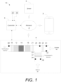
- FIG. 1 schematically shows an exemplary temperature control system 10 that may help implement the methodologies of the present disclosure.
- the system 10 may include various HVAC equipment components 8 configured to condition the interior air of the structure, i.e., to selectively heat and cool the interior air of the structure.
- the system 10 includes a controller 6 for controlling the HVAC equipment components 8.
- the system 10 may include a server 5, a network 4 and/or a mobile device 2.
- the methods and devices of the present disclosure may be practiced with the HVAC system 10 and/or as part of HVAC system 10.
- the server 5 may be directly communicatively connected to the controller 6 and the mobile device 2 or communicatively connected via the network 4.
- the server 5 may be: various embodiments of a computer including high-speed microcomputers, minicomputers, mainframes, and/or data storage devices.
- the server 5 preferably executes database functions including storing and maintaining a database and processes requests from the controller 6 and/or mobile device 2 to extract data from, or update, a database as described herein below.
- the server 5 may additionally provide processing functions for the mobile device 2 and the controller 6 as will become apparent to those skilled in the art upon a careful reading of the teachings herein.
- the HVAC controller 6 may be directly communicatively connected to one or more of the HVAC equipment components 8 including one or more sensors 31, 32, 33, and/or 34.
- the controller 6 is wirelessly connected to the one or more HVAC equipment components 8 via the network 4.
- the mobile device 2 may be physically or wirelessly connected to the network 4 and/or the controller 6 during selected periods of operation without departing from the teachings herein.
- Components of the system 10 are shown in FIG. 1 as single elements. Such illustration is for ease of description and it should be recognized that the system 10 may include multiple additional components in various embodiments without departing from the teachings herein.
- the controller 6 may be incorporated into the server 5.
- the exemplary HVAC system 10 shown in FIG. 1 includes an HVAC controller 6, which may be or may include a thermostat or a hydronic heat transfer system control in some embodiments.
- the HVAC controller 6 may be configured to communicatively interact with and control various components of the HVAC components 8.
- the HVAC controller 6 may be directly connected to the HVAC components 8 or connected via a network 4 which may be a locally based network or a wider network such as the Internet.
- the mobile device 2 is communicatively connected to the controller 6 so that a user may control the HVAC components 8 using the mobile device 2 via the controller 6.
- the HVAC components 8 include ventilation subsystem (16) and cooling subsystem (14).
- the HVAC components 8 may include a heating system 12, a fan, i.e., a blower, a humidification system 18 and/or any other HVAC components or systems, as desired such as an outside air damper 22 or intake damper 23.
- HVAC components include auxiliary heating and cooling equipment. Exhaust fans 37 and supply air fans 16, removing air from the structure, and moving air into the structure, respectively, may also be used in various embodiments.
- the HVAC components 8 primarily function as a forced air system although auxiliary HVAC components may be used in conjunction to supplement conditioning of the environment within the building.
- auxiliary heat may be provided by electrical resistive heaters, hot water radiant heat, boilers, and/or electric base board heaters in various embodiments.
- the heating system 12 and the cooling system 14 are combined in a forced air system; however, it is contemplated herein that the heating and cooling systems 12 and 14 may be separated.
- a heat pump system may be utilized separate from an air conditioning cooling system 14.
- the HVAC components 8 include any number of intake and outtake dampers.
- a filter 21, a first damper 22, and a second damper 23 are utilized consistent with the teachings herein.
- the damper 22 may be in communication with outside air and the fan 16 is in communication with one or more of the dampers 22 and 23 within a ducting 24, for example.
- the dampers 22 and 23 may be selectively actuatable as a group or individually in various embodiments.
- the HVAC components 8 may include cooling equipment, which may include more than one unit and/or more than one stage of cooling.
- the HVAC components 8 are selectively in gaseous communication with exterior ambient air and including operability to intake and/or vent exterior ambient air.
- the ventilation equipment may provide different levels of air movement as described herein below.
- the HVAC components 8 may include other units such as a humidifier unit, a dehumidifier unit, a UV filter unit and/or any other suitable HVAC unit and/or equipment as desired.
- the HVAC components 8 may include one or more sensors, such as an exterior ambient air temperature sensor 31, an exterior humidity sensor 32, a return temperature sensor 33, and/or a smoke detector 34.
- the sensors 31, 32, 33, and 34 may be directly or indirectly communicatively connected to the controller 6.
- the exterior ambient temperature sensor 31 is configured to measure a temperature of the outside air and, for example, may be mounted to an exterior of the building, or factory installed as part of the HVAC components 8.
- the exterior humidity sensor 32 may also be mounted external to ducting of the HVAC components 8 or factory installed as part of the HVAC components 8.
- An interior temperature sensor 35 measures a temperature of the interior air of the building.
- the sensor 35 may be internal to the controller 6 or external.
- an interior humidity sensor 36 measures the humidity of the interior air of the structure.
- the sensor 36 may be internal to the controller 6 or external.
- the controller 6 may obtain outside, i.e., exterior air temperature and/or humidity conditions through an online weather service or may be in communication with a building automation system having equivalent measuring functionality.
- predicted weather conditions may be utilized by the controller 6.
- the interior and exterior humidity sensors 36 and 32 are optional.
- sensors 33 and 34 are optional.
- the network 4 may be any suitable series of points or nodes interconnected by communication paths.
- the network 4 may be interconnected with other networks and contain sub network(s) such as, for example, a publicly accessible distributed network like the Internet or other telecommunications networks (e.g., intranets, virtual nets, overlay networks and the like).
- the network 4 may facilitate the exchange of data between and among the HVAC components 8, the HVAC controller 6, and the sensors 31, 32, 33, 34, 35 and 36; although in various embodiments the HVAC controller 6 may be directly connected to the HVAC components 8 and/or the sensors 31, 32, 33, 34, 35 and 36.
- the mobile device 2 may include one or more applications that the user may operate. Operation may include downloading, installing, turning on, unlocking, activating, or otherwise using the application in conjunction with the controller 6.
- the application may comprise at least one of an algorithm, software, computer code, executable instruction sets and/or the like, for example, mobile application software.
- the application may be utilized remotely through a website accessible through the world wide web.
- FIG. 2 shows the exemplary HVAC controller 6.
- the controller 6 includes a central processing unit (CPU) 50, random access memory (RAM) 52, input/output circuitry 54 for connecting peripheral devices such as a storage medium 56 to a system bus 60, a display adapter 58 for connecting the system bus 60 to a display device, a user interface adapter 62 for connecting user input devices such as various dials buttons and/or keypads, to the system bus 60, and a communication adapter 64 for connecting the controller 6 to the network 4.
- the memory 52 and storage medium 56 may be used to store any appropriate information such as HVAC control routines or code, historical performance data, HVAC system and/or HVAC controller parameters, one or more programmable schedules for changing HVAC system parameters over time, etc.
- the central processing unit 50 is preferably one or more general-purpose microprocessor or central processing unit(s) and has a set of control algorithms, comprising resident program instructions and calibrations stored in the memory 52 and executed to provide the desired functions.
- an application program interface is preferably executed by the operating system for computer applications to make requests of the operating system or other computer applications.
- the description of the central processing unit 50 is meant to be illustrative, and not restrictive to the disclosure, and those skilled in the art will appreciate that the disclosure may also be implemented on platforms and operating systems other than those mentioned.
- HVAC controller 6 may include any number of suitable components related to effecting control of the HVAC system 10.
- HVAC controller 6 may include a user interface 68 which may be graphical.
- the user interface 68 may include one or more displays, switches, and/or buttons that a user may actuate or otherwise control.
- a touchscreen display may be provided to display the user interface 68 and provide interaction therewith.
- one or more of a cooling device, heating equipment and/or ventilation equipment may be distinct systems controlled, either directly or indirectly, by the HVAC controller 6.
- the HVAC controller 6 may separately control each component 8.
- HVAC system parameters may include set points for heating, cooling, humidity, etc., modes for ventilation equipment, fan settings, and the like and as further described below.
- the HVAC controller 6 may include one or more internal sensors 65, such as a temperature sensor and/or a humidity sensor.
- the internal sensors 65 may be in addition to the sensors 35 and 36 and may be used for supplemental or redundancy purposes, as exemplary.
- the HVAC controller 6 may include one or more outputs configured to issue operation commands to the HVAC components 8. It is contemplated herein that the HVAC controller 6 may be configured to execute any method of the present disclosure.
- the HVAC controller 6 may be communicatively connected to one or more sensors connected external to a building structure and external to a housing of the controller 6. The connection may be via wire or via a wireless embodiment of the network 4.
- the HVAC controller 6 may maintain in its memory an operating schedule that may be used to control the HVAC system based upon time and/or day.
- the schedule may, for example, be a daily programmable schedule or any other schedule.
- the schedule may have a number of days and one or more time periods for each of at least some of the days.
- the nominal schedule may include an "occupied", an "unoccupied", and a "stand-by" time period for each of the days of a week.
- the schedule may have at least one set point associated with each of the one or more time periods.
- the schedule may be maintained in the memory 52, and may be modified by an end user in various embodiments.
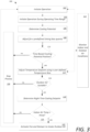
- FIG. 3 shows a control scheme 100 for operating the controller 6 and the HVAC components 8.
- the control scheme 100 is shown as discrete elements, such an illustration is for ease of description and it should be recognized that the functions performed by the control scheme 100 may be combined in one or more devices, e.g., implemented in software, hardware, and/or application-specific integrated circuitry (ASIC) and executed, in some cases, concurrently or in parallel. For example, monitoring of the various sensors may be executed concurrent with any number of execution steps.
- ASIC application-specific integrated circuitry
- the control scheme 100 is directed at operating efficiencies that can be gained from utilizing exterior ambient conditions to ventilate outside air into the structure and/or condition the interior environment. For example, during warm summer months, the coldest part of the day is typically in the early morning, such as between 4:00am and 6:00am. As set forth further below, during this early morning time, the controller 6 instructs one or more of the HVAC components 8 to operate to effect the intake of cool exterior air (and either passively or actively exhaust warm interior air) based upon exterior air conditions, interior air conditions, the usage of the HVAC components 8 during the previous day, and current settings of the HVAC components 8.
- the controller 6 may instruct the HVAC components 8 to intake cool exterior air, and optionally to exhaust warm interior air to decrease the temperature of the interior air of the structure to a temperature between the occupied heating set point and the occupied cooling set point of the HVAC components 8, as shown in FIG. 7 .
- the control scheme 100 is configured, in one exemplary implementation, to operate one or more of the HVAC components 8 using the controller 6 to condition the interior environment.
- the control scheme 100 is initiated at step 102 whereby the controller 6 operates the HVAC components 8 based upon a user's predefined or default operating parameters, and the results of a prior iteration of the control scheme 100.
- the control scheme 100 operates during cool mornings to proactively ventilate the building with cool exterior air based upon the operation of the HVAC components 8 during a previous period, e.g., during the previous day.
- the HVAC components 8 may transition between an occupied state and an unoccupied state.
- the control scheme 100 is operated only at a predetermined time range. While operating in an occupied state, the controller 6 typically operates to maintain interior air conditions at desired levels, for example, levels directed at maintaining comfortable conditions for occupants, e.g., a user-supplied set point. In one embodiment, while in the predetermined time range, the controller 6 executes the control scheme 100 to maintain interior air conditions at a second set of preferential conditions, which may be directed at a different set of objectives, e.g., energy conservation, equipment wear reduction, and/or improvement of indoor air quality.
- objectives e.g., energy conservation, equipment wear reduction, and/or improvement of indoor air quality.
- operation of one or more of the HVAC components 8 may be based upon operation that occurred during the previous period.
- the previous period may be, for example the previous day, i.e., the previous 24 hours.
- the previous period may be, for example, the previous day less any time duration during which the process 100 operated. For example, if the process 100 operated for two hours during the previous day (for example, from 4:00am to 6:00am), the previous period may be 22 hours (i.e., 24 hours minus 2 hours).
- the controller 6 may execute the control scheme 100 during a predefined operating time range.
- the controller 6 may then deactivate the control scheme 100 after or outside of the predefined operating time range.
- the operating time may be between 4:00am and 6:00am, for example.
- the operating time range may be user-defined.
- the operating time range may initiate at any suitable predefined time and may last for any suitable predefined duration.
- operating time may be defined based upon occurrence of an event.
- operating time may begin at any suitable predefined time, and not terminate until block 116 or block 120 of figure 3 is "no".
- operating time may be defined based upon historical trending of the coolest part of the day.
- a photocell could be utilized to estimate a time of dawn, and then, in turn, apply that time to the next day's predetermined start and stop times of the operating range.
- a start and stop time of the control scheme 100 may be determined based upon monitored exterior air temperature. For example, a time associated with a lowest temperature reading may be set as the start time or a predetermined time period before the monitored lowest temperature may be set as the start time and a predefined duration after the start time may be calculated for the stop time.
- FIGS. 5 and 6 graphically illustrate exemplary time ranges of exemplary operation of a cooling system and a heating system.
- FIG. 5 graphically shows a first sum of products of operational time and operational load of the cooling system and a second sum of products calculation for operational time and operational load of the heating system.
- the controller may difference the second sum of products from the first sum of products.
- a positive result indicates cooling potential, while a zero or negative result indicates no cooling potential.
- FIG. 6 shows an alternative to a sum of products calculation.
- cooling and heating equipment wherein cooling load output and heating load output are obtained as a function of operating load may be represented with respect to operating time.
- the controller may execute a first integral calculation for an operational load of the cooling system as a function of operational time over the first time range, execute a second integral calculation for an operational load of the heating system as a function of operational time over the first time range and then difference the second integral from the first integral. Similar to above, a positive result indicates cooling potential, while a negative result indicates no cooling potential.
- the control scheme 100 subtracts a time bias quanta from the cooling potential (cp).
- the time bias may be defined or set by the user. This time bias is subtracted from the cooling potential value to inhibit use of the control scheme 100 when only slightly more cooling than heating was observed in the previous period. In such a situation, it is likely that having the equipment cool the structure in the early morning may actually cause the heating function to be energized prior to the "heat of the day," which may be around 3:00pm.
- a user defined time bias may be adjusted or may be a default value, but as a default, that value may be set to 60 minutes.
- the control scheme 100 determines whether the entc value is positive or negative. If the entc value is zero or negative, the control scheme 100 stops the process 100 until the next time period 130. In other words, if the entc value is zero or negative (after being biased by the user defined time bias), then conditions may, undesirably, cause the controller 6 to effectuate the heating system 12 during the upcoming period, before the heat of the day, if the control scheme 100 were to ventilate the air in the building.
- the control scheme 100 is not operated to utilize the exterior air damper 22, and/or fan 16 to intake outdoor air and/or the exhaust fan(s) 37 to exhaust interior air thereby avoiding cooling the structure undesirably and avoiding inefficient use of the heating system 12 during the upcoming time period.
- the control scheme 100 measures indoor and outdoor air conditions.
- the control scheme 100 adjusts an exterior air temperature measurement using a user-defined or default temperature bias. Factoring in a temperature bias will cause the controller 6 to be less likely to determine that the exterior air is suitable to use for cooling the structure. The greater the temperature bias, the less likely the controller 6 will find the exterior air suitable.
- the temperature bias is added to compensate for electrical consumption of the equipment which operates during the control scheme 100 to cool the structure. For example, while running the fan(s) 16 alone consumes less electricity than running a number of the other HVAC components 8, e.g., compressors, condenser fans, etc., there is still energy consumption used by simply running the fan 16.
- the "break even" point for venting the exterior air is not when the exterior air temperature or enthalpy is slightly less than that of the interior air temperature or enthalpy, respectively, but is when the interior air temperature or enthalpy is significantly greater than the exterior air temperature or enthalpy, respectively, so that the cost to utilize the intake of exterior air and the exhausting of indoor air (either passively or actively) for cooling is profitable, in terms of the cost per kWh of heat transfer (or electricity consumption per kWh of heat transfer). Based on factors including, but not limited to, indoor air humidity set points, fresh air intake considerations, specific equipment characteristics, and the local cost of electricity, the optimal temperature or enthalpy difference may change. Enthalpy of the exterior air may be determined or estimated using exterior temperature and humidity measurements from the exterior temperature sensor 31 and the exterior humidity sensor 32 using known calculation techniques and/or modeling processes.
- the control scheme 100 analyzes the exterior ambient air to determine whether the exterior air is suitable.
- the determination of whether the exterior air is suitable may be based upon the use of industry standard enthalpy calculations, or temperature calculations, or some combination of the two. Specifically, the interior air condition and exterior air condition is measured. The suitability may be based upon interior and exterior air temperature and, optionally, humidity values, provided by the sensors, such as interior temperature sensor 35, exterior temperature sensor 31, interior humidity sensor 36, and exterior humidity sensor 32, network values, etc., or may simply utilize interior and exterior air temperature sensors 35 and 31, respectively, network values, etc.
- the control scheme is stopped at 130 and the controller 6 does not operate the damper(s) 22 and 23 and the fan 16 to intake exterior air, and optionally the exhaust fan(s) 37 to exhaust interior air.
- the controller 6 determines a night time cooling set point.
- the night time cooling set point is determined by subtracting the occupied heating set point, e.g., a "heating" set point on a conventional thermostat, from the occupied cooling set point, e.g., a "cooling" set point on a conventional thermostat, multiplying that value by a bias value (between 0 and 1, with a default of 0.67, for example), and then subtracting that product from the occupied cooling set point.
- the bias value may be used, for example, to affect the degree of pre-cooling within the building, with a larger biasing value resulting in more pre-cooling and a smaller biasing value resulting in less pre-cooling.
- ntcsp ocsp ⁇ ocsp ⁇ ohsp ⁇ udbv
- enthalpy values could be entered in place of temperature values to determine the ntcsp.
- the value of the ntcsp could be expressed in terms of enthalpy rather than simple temperature.
- indoor air enthalpy and outdoor air enthalpy could be used rather than simple temperatures.
- control scheme 100 has determined the ntcsp, it compares the ntcsp with the interior air temperature. If the interior air temperature is less than or equal to the ntcsp, then the control scheme 100 terminates all sequences 130.
- the control scheme 100 energizes, for example, a relay, triac output, network signal, etc., which will, at least, energize equipment which causes cool outdoor air to enter the building, e.g., the fan 16, and open the exterior air damper 22 (also known as the fresh air damper 22).
- the control scheme 100 may energize any connected exhaust equipment such as the exhaust fan(s) 37, which may remove air from the building, to help facilitate economization of the primary heating, cooling, and ventilation equipment.
- the relay, triac output, network signal, etc. will remain active until conditions change in blocks 110, 116, or 120.
- the controller will terminate step 122 if the controller 6 is transitioned to an occupied state.
- the controller 6 will terminate step 122 if a current time is outside of the predefined time range.
- the controller 6 may transition the one or more of the HVAC components 8 to a stopped operating state 130.
- the control scheme 100 may be configured to transition out of step 130 after a predefined duration of time or upon occurrence of an event.
- FIG. 4 shows a control scheme 200 for operating the controller 6 and the HVAC components 8 illustrating operation of the system 10 using enthalpy values determined from temperature and humidity measurements.
- the control scheme 200 is shown as discrete elements, such an illustration is for ease of description and it should be recognized that the functions performed by the control scheme 200 may be combined in one or more devices, e.g., implemented in software, hardware, and/or application-specific integrated circuitry (ASIC) and executed, in some cases, concurrently or in parallel. For example, monitoring of the various sensors may be executed concurrent with any number of execution steps.
- ASIC application-specific integrated circuitry
- the control scheme 200 is directed at operating efficiencies that can be gained from utilizing exterior ambient conditions to ventilate outside air into the structure and/or condition the interior environment. For example, during warm summer months, the coldest part of the day is typically in the early morning, such as between 4:00am and 6:00am. As set forth further below, during this early morning time, the controller 6 instructs one or more of the HVAC components 8 to operate to effect the intake of cool exterior air (and either passively or actively exhaust warm interior air) based upon exterior air conditions, interior air conditions, the usage of the HVAC components 8 during the previous day, and current settings of the HVAC components 8.
- the controller 6 may instruct the HVAC components 8 to intake cool exterior air, and optionally to exhaust warm interior air to decrease the temperature of the interior air of the structure to a temperature between the occupied heating set point and the occupied cooling set point of the HVAC components 8, as shown in FIG. 7 .
- the control scheme 200 is configured, in one exemplary implementation, to operate one or more of the HVAC components 8 using the controller 6 to condition the interior environment.
- the control scheme 200 is initiated at step 202 whereby the controller 6 operates the HVAC components 8 based upon a user's predefined operating parameters, e.g., set points, and the results of a prior iteration of the control scheme 200.
- the control scheme 200 operates during cool mornings at predefined or determined times to proactively ventilate the building with cool exterior air based upon the operation of the HVAC components 8 during a previous period, e.g., during the previous day.
- the controller 6 may execute the control scheme 200 during a predefined operating time range, a predefined time duration having a determined start time based upon prior measured exterior air conditions and/or photocell measurements.
- control scheme 200 determines a cooling potential of the interior air based upon the previous period, e.g., the previous day, similar to step 106 described herein above with respect to control scheme 100.
- the control scheme 200 subtracts a time bias or buffer value from the determined cooling potential (cp). This time bias is subtracted from the cooling potential value to prohibit use of the control scheme 200 when only slightly more cooling than heating was observed in the previous period.
- the control scheme 200 determines whether the entc value is positive or negative or zero.
- the entc value is the difference between the cooling potential value and the time bias or buffer value. If the entc value is zero or negative, the control scheme 200 stops the process 200 until the next time period by transitioning the control scheme 200 to a stop state 230.
- the control scheme 200 measures interior and exterior air conditions including an exterior temperature and exterior humidity.
- the control scheme 200 determines the exterior enthalpy using the monitored exterior air conditions including temperature and humidity. Enthalpy of the exterior air may be determined or estimated using exterior temperature and humidity measurements from the exterior temperature sensor 31 and the exterior humidity sensor 32 using known calculation techniques and/or modeling processes.
- the control scheme 200 adjusts the determined enthalpy value using a buffer value. Factoring in a buffer will cause the controller 6 to be less likely to determine that the exterior air is suitable to use for cooling the structure. The greater the buffer value, the less likely the controller 6 will find the exterior air suitable.
- the buffer value is added to compensate for electrical consumption of the equipment which operates during the control scheme 200 to cool the structure. For example, while running the fan(s) 16 alone consumes less electricity than running a number of the other HVAC components 8, e.g., compressors, condenser fans, etc. in combination with each other, there is still energy consumption used by simply running the fan 16.
- the "break even" point for venting the exterior air is not when the exterior air temperature or enthalpy is slightly less than that of the interior air temperature or enthalpy, respectively, but is when the interior air temperature or enthalpy is significantly greater than the exterior air temperature or enthalpy, respectively, so that the cost to utilize the intake of exterior air and the exhausting of indoor air (either passively or actively) for cooling is profitable, in terms of the cost per kWh of heat transfer (or electricity consumption per kWh of heat transfer). Based on factors including, but not limited to, indoor air humidity set points, fresh air intake considerations, specific equipment characteristics, and the local cost of electricity, the optimal temperature or enthalpy difference may change.
- the control scheme 200 analyzes the exterior ambient air to determine whether the exterior air is suitable. The determination of whether the exterior air is suitable may be based upon the use of industry standard enthalpy calculations, or temperature calculations, or some combination of the two. In one embodiment, the interior humidity value and exterior humidity values are compared. If the controller 6 determines that the exterior air is not suitable for intake, e.g., interior conditions are preferable to exterior conditions, then the control scheme 200 is stopped at 230 and the controller 6 does not operate the damper(s) 22 and 23 and the fan 16 to intake exterior air, and optionally the exhaust fan(s) 37 to exhaust interior air.
- the controller 6 determines a night time enthalpy cooling set point similarly to the process described herein above with respect to control scheme 100 only using enthalpy values and not exclusively temperature values.
- the night time cooling set point 218 is determined by subtracting the occupied enthalpy heating set point, from the occupied enthalpy cooling set point, and then multiplying that value by a bias value (between 0 and 1, with a default of 0.67, for example), and then subtracting that product from the occupied enthalpy cooling set point.
- a bias value between 0 and 1, with a default of 0.67, for example
- control scheme 200 has determined the ntcsp, it compares the ntcsp with the interior enthalpy. If the interior air enthalpy is less than the ntcsp, then the control scheme 200 terminates all sequences by transitioning to block 230.
- the control scheme 200 energizes, for example, a relay, triac output, network signal, etc., which will, at least, energize equipment which causes cool outdoor air to enter the building, e.g., the fan 16, and open the exterior air damper 22.
- the process may energize any connected exhaust equipment, which may remove air from the building, to help facilitate economization of the primary heating, cooling, and ventilation equipment.
- the relay, triac output, network signal, etc. will remain active until conditions change in blocks 210, 216, or 220.
- the controller will terminate step 222 if the controller 6 is transitioned to an occupied state.
- the controller 6 will terminate step 222 if a current time is outside of the predefined time range.
- the controller 6 may transition the one or more of the HVAC components 8 to a stopped operating state 230.
- the control scheme 200 may be configured to transition out of step 230 after a predefined duration of time or upon occurrence of an event.
- FIG. 7 graphically shows operation of the HVAC system for venting exterior air into a structure with respect to indoor temperature, while outdoor air is suitable for cooling 116.
- specific condition ranges related to the structure's interior and monitored exterior temperature result in venting exterior air to the interior of the structure.
- venting of the exterior air to the inside will occur when: (1) the time biased cooling potential is positive; and (2) the indoor temperature is greater than a cooling set point associated with an unoccupied status of the structure, i.e., (second time range).
- the criteria for venting of the exterior air to the inside is satisfied in zone 300.
- the controller 6 may utilize a thermostat of the HVAC components 8.
- a capacitor may be set to charge when the Y1 terminal is activated, with a resistor inline with the capacitor, which acts as a regulator for the current.
- the same capacitor could also be charged when the Y2 terminal is activated, which would also have an inline "regulator” resistor.
- the heating terminals could also have a capacitor which is charged via the W1 and W2 terminals, with "regulating" resistors in-line. The charges of the two capacitors would be discharged via a short, which is regulated by a (high value) resistor.
- the total charges of each of the two capacitors could be compared via an integrated circuit (IC) to determine the cooling potential (as set forth above) for the upcoming time period.
- IC integrated circuit
- the time bias could be incorporated by adding a potentiometer to the circuit.
- some level of circuit integration could be added. For example, a time clock of the thermostat may be incorporated into the process. Similarly, the occupied set points (or at least the lowest cooling set point) may be incorporated into the process.
- interior humidity and exterior humidity sensors are optional, and a provision may be made to utilize both or only one type of humidity sensor.
- the system 10 utilizes a default, predefined humidity reading as a reference marker to compare measurements from the exterior humidity sensor.
- the system 10 may be configured to assume that the interior humidity is at a first predefined level under a first set of criteria, e.g., a reading from the exterior humidity sensor after running the control scheme 100 for at least a first time period.
- a first set of criteria e.g., a reading from the exterior humidity sensor after running the control scheme 100 for at least a first time period.
- Another example may assume that the interior humidity is simply at a predefined level.
- the system 10 could compare the assumed humidity value and the measured value until the exterior humidity levels exceed 50% relative humidity, at which point the assumed interior humidity level would stay at 50%, while the actual relative humidity value for the exterior humidity levels would be reflected in the system's 10 calculations.
- the control scheme 100 may stop if the exterior humidity is above and/or below a predetermined threshold.
- ntcsp On thermostat embodiments having a switch to select "cool” (only) or “heat” (only), there could be a calculated or user-defined ntcsp (see above).
- the calculated ntcsp could use a user defined temperature offset value which may be set via programming the thermostat, or may simply use a default value of a certain number of degrees less than the lowest cooling set point on the thermostat.
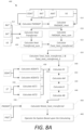
- FIG. 8A shows a block diagram illustrating an exemplary process 400 for controlling the system 10 based upon a calculated anticipated heat energy transfer metric.
- FIG. 8A may show a specific order of method steps, the order of the steps may differ from what is depicted.
- the methods or steps shown in the flowcharts and described in the accompanying text are not constrained to a particular order or sequence. In various embodiments, some of the steps thereof can occur or be performed concurrently or with partial concurrence and not all the steps have to be performed in a given implementation depending on the requirements of such implementation. Further, the order or sequence of any process or method steps may be varied or re-sequenced according to alternative embodiments. Other substitutions, modifications, changes, and omissions may be made in the design, operating conditions and arrangement of the exemplary embodiments without departing from the scope of the present disclosure. All such variations are within the scope of the disclosure.
- FMOADP (70 °F - 55 °F) / (70 °F - 50 °F), which equals a value of 0.75, meaning that the outdoor air damper 22 is open 75%, where a '1' value is defined as completely open and a '0' value is defined as closed.
- a discharge air temperature may be utilized to determine FMOADP instead of the MAT variable as one skilled in the art will recognize upon a careful reading of the teachings herein.
- the FMOADP could be calculated and trended (based on time or time in different states/values) for use later. For example, specific calculations of FMOADP at noon and at 2pm, may be trended to determine position at 1pm or 3pm. In one embodiment, the FMOADP may be used in calculating the energy (or heat) added to, or removed from the structure via the "fresh air intake", or intake of outdoor air.
- heat transfer due to FMOADP and ventilation status may be calculated when considering temperatures.
- historical heat transfer rates due to the intake of outdoor air may be used to predict the heat transfer going forward.
- the heat transferred during the last same day of the previous week could be used to determine another day's anticipated value, or may begin as the average heat transferred the last same day of the week and month for the first year, and/or then in later years, the average heat transferred on the same day of the week and month in preceding years.
- a church might have nominal load demand on every day of the week except Sunday. Basing the next day's predicted cooling potential based on the last Sunday's actual load demand, or on the same Sunday from the previous year's load demand may be beneficial instead of using the prior day's load demand.
- a "VS constant" can be multiplied by each individual climate control equipment's value for VS, such that the value of VS for each individual climate control equipment shall be in proportion to its volumetric flow rate in relation to all other climate control equipment. For example: If two pieces of climate control equipment are used, one capable of moving 4,000 CFM (6796 m 3 /h) (unit #1), and another capable of moving 8,000 CFM (13592 m 3 /h) (unit #2), then the VS constant for unit #1 would be 0.5, and the VS constant for unit #2 would be 1.
- FMOADP_heat 1 * (60 °F - 70 °F) * 0.1, which reduces to - 1 °F (-18.3°C).
- the system 10 may determine FMOADP_Heat_sum.
- FMOADP_Heat_sum represents a heat transferred (based on the FMOADP_heat metric), resulting from venting outdoor air into, and indoor air out of, the building structure for the entire period being measured (e.g., a whole day, 22 hours, one week, etc.).
- FMOADP_Heat_sum represents a heat transferred (based on the FMOADP_heat metric), resulting from venting outdoor air into, and indoor air out of, the building structure for the entire period being measured (e.g., a whole day, 22 hours, one week, etc.).
- multiple climate control equipment i.e.
- FMOADP_Heat_sum can be summed with the FMOADP Heat sum of the other networked and/or controlled systems, however, the FMOADP_heat calculation of each individual unit would likely need to have a "VS constant" (as described above) applied to the FMOADP_heat value for each individual unit.
- the system 10 may calculate a heat transfer metric (HeatTransferred) due to a HVAC unit's operation of mechanical heating or cooling (e.g. using gas burners, refrigerant based systems, etc.), iteratively at predetermined sampling intervals, e.g., at a time interval ti, as follows, while understandably similar calculations could be made by replacing the temperature variables for enthalpy variables and modifying the equations slightly.
- the operation of the mechanical cooling or mechanical heating is preferably considered to ascertain the heat transfer into or out of a structure during a period of time.
- the energy transferred may be fairly easily calculated, however, in a situation where the volumetric air flow is unknown, and for the purposes of the disclosure, the total heat transfer, as a result of a HVAC unit's mechanical operation, (e.g., use of gas burners for heating, refrigeration based cooling systems, compressors, etc.) may require the formation of a new metric.
- FIG. 8B shows an alternative process 400' for implementation in the system 10 without sensors 31, 33, 38, and 39 being used for calculating HeadTransferred at step 418'.
- FMOADP_Heat_sum is then calculated at step 416' based upon a FMOADP_heat having a 0 value. As one skilled in the art may understand after considering the teachings disclosed herein that the units of measurement will change from degree-minutes to minutes.
- HeatTransferred_sum ⁇ a b HeatTransferred t dt
- a separate HeatTransferred_sum may be determined for each system and then may be added together.
- the process 400 calculates a Total_heat_transferred (at step 422) by adding HeatTransferred_sum with FMOADP _Heat_sum.
- Total_heat_transfered then represents a total °F-minutes (°C-minutes) of heat transferred into the structure by the HVAC unit during the time period (i.e. 22 hours, 24 hours, one week, etc.).
- the heat energy was transferred into the structure (the heating system 12 was operated to introduce heat into the structure). If the value would have been negative, then heat energy would have been transferred out of the structure by the system 10 via one or more of the components, e.g., the ventilation system 16.
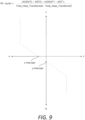
- the total_heat_transferred can be used to determine the slope M 440, which in turn can be used to predict the next period's heat transfer (NTotal_heat_transferred 450).
- the total_heat_transferred for at least two historic time periods can be calculated (i.e. two days, two 6 hour periods, two weeks, or whatever period is determined to be most effective in predicting the next period's heat transfer desired).
- the total_heat_transferred for the first historic time period could be total_heat_transferred_1, and for the second historic time period could be called total_heat_transferred_2, and so on, as determined in step 424.
- the process 400 further includes determining an average outdoor air temperature for a period (AODAT) at steps 430 and 432.
- AST ⁇ a b f x dx / b ⁇ a
- Total_heat_transferred HeatTransferred_sum + FMOADP_Heat_sum.
- a 22 hour, 24 hour, period may be used to define a "day” or “period”, however it should be understood that when determining a slope of a graph, it may be beneficial to use different time periods.
- HeatTransferred_sum and FMOADP_Heat_sum can use identical time periods for determining Total_heat_transfered, and any equations that combine HeatTransferred_sum, FMOADP_Heat_sum, Total_heat_transferred, AODAT, and AST will likely require that identical time periods be used, it should also be understood that in the application of determining the slope ((AODAT 2 - AST 2 ) - (AODAT 1 - AST 1 )) / (Total_heat_transferred 2 - Total_heat transferred 1 ) that smaller time periods may be more suitable, e.g., a 6 hour time period., although the disclosure herein contemplates that various time periods may be utilized consistent with the teachings herein.
- the process 400 calculates a slope 'M' based upon two or more iterations of AODAT, AST, and the Total_heat_transferred calculations at step 440.
- the system 10 may apply various statistical conditioning or averaging of the slope M to maintain consistency. Because the slope of the graph relates Total_heat_transferred to (AODAT - AST) it should remain fairly constant, since the slope is directly related to the R-value of the structure's envelope (as well as other minor factors- in some cases).
- the difference between the beginning of the time span and the end of the time span may be defined as a week (i.e., 7 days), while M, could be recalculated every six hours, or once a day, for example.
- M could be recalculated every six hours, or once a day, for example.
- B is a y-intercept used on FIG. 9 that illustrates a relationship of Total_heat_transferred to (AODAT - AST).
- a NTotal_heat_transferred value is determined.
- weather predictions may be utilized in conjunction with the AM slope to determine the next period's (e.g., day), anticipated/projected Total_heat_transferred, i.e., NTotal_heat_transferred.
- the AM slope permits incorporating set point data into the equation for determining the next day's anticipated/projected Total_heat_transferred. For example: a church may not have need for cooling any day except Sunday.
- a predicted space temperature may be determined by taking all relevant data regarding scheduled set point information (which correlates space temperature set points with times), default space temperature set points, historical user set point data, etc.
- scheduled set point information which correlates space temperature set points with times
- default space temperature set points e.g., 1 z x i / Z
- ASTSP ⁇ a b f x dx / b ⁇ a
- PAODAT is the predicted average outdoor air temperature. In one embodiment, this value may be determined from an average of the predicted outdoor air temperatures (PODAT) over a future time period. In one embodiment, PAODAT may be based upon forecasted predictions from subscription or governmental sources, e.g., weather forecasting information. In one embodiment, PAODAT may simply be based upon a rolling average temperature period over a predefined number of time periods, e.g., days. As there are many ways to determine PAODAT, which one skilled in the art will recognize upon a careful reading of the disclosure herein may understand there are many ways to determine PAODAT.
- PAST is the predicted average space temperature for the following time period (i.e. the next day or next 12 hours, etc.). There are many ways to calculate PAST. In one embodiment of the invention, PAST may be equal to the AST of a chosen historical time period, such as the day before, or the same day of the previous week. The limitation of setting PAST equal to a previous time period's AST is that this method does not take into account the future set point temperature schedule.
- PAST is a function of predicted outdoor air temperature (PODAT) and the future set point temperature.
- PODAT predicted outdoor air temperature
- the space temperature could be plotted versus the outdoor air temperature under different set point temperature conditions. From this data, functions to represent ST versus ODAT, under different set point conditions, could be determined. Any data that derives a non-functional result would be negated or accounted for differently.
- the PODAT could be substituted for the ODAT in the functions.
- PAST may be calculated based upon Newton's "Law of Cooling (Warming).”
- Newton's “Law of Cooling” states that the rate at which the temperature changes of one body is proportional to the difference in the temperatures of the body and the environment.
- the environment includes the outside as well as the effects of internal heat sources, such as computers, lights, etc..
- both k and C can be determined. Two data points are used to determine how the structure naturally warms. Using historical data ( t 1 , ST 1) and ( t 2, ST 2) where the numbers 1 and 2 indicate first and second data points while YODAT1 remains constant.
- the value of k is a value dependent on the thermal characteristics of the structure.
- the value C would be calculated with different values of YODAT1 and ST1.
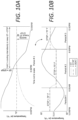
- FIGS. 10A and 10B illustrate, there may be a period of natural warming, a steady period (temperature at STSP), and a period of natural cooling.
- t 1 t 2 YODAT 1 t 2 ⁇ t 1 ⁇ C k e k t 2 ⁇ e k t 1 ⁇ t 2 t 3
- STSP dt STSP t
- the predicted average space temperature (PAST) for the next period, e.g. the next day, could be extracted from a user-supplied temperature schedule, default temperature schedule, historical user entry data, a combination of these, the equations given herein above, etc.
- the NTotal_heat_Transferred value is that which the system 10 would try to achieve in order to condition the structure in preparation of the next day, however, upper and lower limits may inhibit the value being too high or low, and/or upper and lower limits may inhibit the operations to achieve NTotal_heat_Transferred in order to keep the space temperature within reasonable limits.
- the appropriate limits on the operations of the systems may be understood by one skilled in the art, when considering the teachings herein disclosed.
- volumetric flow rates of the system 10 are known in real units of measure, then industry standard calculations could be made to determine the real value, in terms of real units of measure, of heat transfer. Also an amount of energy produced inside the structure due to people, computers, lights, etc., which is referred to as IHEPIS (the value of the x-intercept of the graph in FIG. 9 multiplied by -1) could be calculated using real units of measure.
- IHEPIS the value of the x-intercept of the graph in FIG. 9 multiplied by -1
- the R-value of the structure's envelope could be computed using the slope of (AODAT - AST) / Total_heat_transferrred, although if for instance a window was left open, the resulting heat transfer would affect the calculated R-value.
- k could be used to calculate the effective thermal capacity of the structure.
- the system 10 may operate various components to effect ventilation, cooling, and/or heating at step 460 based upon the calculated NTotal_heat_Transferred value.
- the following table shows the AODAT, AST, and total_heat_transferred over three days (i.e. three time periods). Please note that this example may not be typical, but rather is given for illustrative purposes.
- the system would cool the structure on Thursday, transferring -267°F-min (-166.1 °C/min) of heat energy to do so. Therefore, during the time when conditions were optimal (usually from 4-6am), the system would bring in cool outdoor air for a certain amount of time until the total_heat_transferred reached the -267°F-min (-166.1 °C/min) necessary to meet the day's predicted cooling requirements.
- the system could also activate mechanical cooling (i.e. compressors, refrigeration systems, etc.) to cool the structure. If NTotal_heat_transferred were a positive value, then the system could heat the structure instead of cooling it. If opportune, this could be done during the heat of the day by bringing in outdoor air and exhausting indoor air, or alternatively, with mechanical heating (i.e. heat pumps, etc.) if conditions warranted such action.
- IHEPIS The internal heat energy produced inside a structure, due to things like lighting, computers, etc. is referred to herein as: "IHEPIS”.
- space temperature set point may be used rather than space temperature to operate many of the functions, calculations, and equations disclosed herein.
Description
- This invention relates to temperature control of buildings and other structures, and more particularly to predictive systems and methods for heating, cooling and/or ventilating buildings and other structures.
- The statements in this section merely provide background information related to the present invention and may not constitute prior art.
- Temperature control systems such as heating, ventilation, and air conditioning (HVAC) systems of structures, are operable to condition the interior air of the structure, i.e., to selectively heat and cool the interior air of the structure. The HVAC system includes mechanical systems for heating and cooling air that is delivered into the interior of the structure via ductwork, to selectively heat or cool the interior air.
- Many HVAC systems have electronically controlled exterior air dampers, which are capable (when used in conjunction with the blower of the HVAC system) of circulating "fresh" exterior air into the structure. In addition to HVAC systems having mechanical means (cooling systems, often utilizing compressor(s), condenser fans, blower motors, etc.) to condition the space of the structure, many HVAC systems have the means to utilize cool exterior air to condition the space, via an exterior air damper (also referred to as an "economizer").
- Many structures have electronically controlled exhaust systems, which are capable of exhausting air from the structure. Often, a structure's exhaust system(s) draws air from near the roof of the structure, and exhausts that air to the outside of the structure.
- The operation of the mechanical systems, e.g., cooling, heating, and/or ventilation systems, consumes energy, adds wear and tear to the equipment, and increases the failure rate of that equipment, which may be financially costly. As such, it is desirable to condition the interior air of the structure to desired temperatures by utilizing predictive data. To appreciate the closest prior art reference is made to the following three publications.
US2012/145802 A1 (Peterson Mark W (US) et al. ) discloses an adaptive intelligent circulation control method and system used to help increase the comfort and/or reduce energy usage and equipment wear and is relevant to the preamble ofClaim 1. Similar prior art is disclosed inUS 2016/047569 A1 (Fadell Anthony Michael (US) et al. ) andUS 2016/061473 A1 (Johnson Solid State, LLC ) - A method for operating a temperature control system according to
claim 1 is disclosed. The method includes monitoring an interior temperature of the structure, monitoring an exterior temperature of ambient air outside of the structure, defining a first time range and a second time range, wherein the second time range comprises a duration less that the first time range, associating one or more operating parameters of the ventilation subsystem and the cooling subsystem with the first time range, associating one or more operating parameters of the ventilation subsystem and the cooling subsystem with the second time range, monitoring operational time and operational load of the cooling system for the first time range, predicting a space temperature and an outdoor air temperature for a subsequent time period, controlling the ventilation subsystem during the second time range based upon the monitored operational time and operational load of the cooling subsystem for the first time range, the monitored interior and exterior temperatures, the predicted space temperature, the predicted outdoor air temperature, and the one or more operating parameters of the cooling subsystem associated with the second time range. - This summary is provided merely to introduce certain concepts and not to identify key or essential features of the claimed subject matter.
- One or more embodiments will now be described, by way of example, with reference to the accompanying drawings, in which:
-
FIG. 1 schematically shows an exemplary HVAC system, in accordance with the present invention, -
FIG. 2 schematically shows an exemplary HVAC controller, in accordance with the present invention, -
FIG. 3 is a control scheme for operating the exemplary HVAC system, in accordance with the present invention; -
FIG. 4 is a control scheme for operating the exemplary HVAC system using enthalpy values, in accordance with the present invention; -
FIGS. 5 and6 graphically illustrate exemplary occupied operational time ranges and load output for a cooling system and a heating system for calculation of a cooling potential of a building or other structure, in accordance with the present invention; -
FIG. 7 graphically shows operation of the HVAC system for venting outside air into a structure with respect to indoor temperature, in accordance with the present -
FIGS. 8A and8B are control schemes for operating the temperature control system, in accordance with the present invention; -
FIG. 9 graphically illustrates a heat transfer metric with respect to temperature, in accordance with the present invention; and -
FIGS. 10A and 10B graphically illustrates exemplary operating metrics of the temperature control system, in accordance with the present invention. - The meanings identified below do not necessarily limit the terms, but merely provide illustrative examples for the terms. The meaning of "a," "an," and "the" includes plural reference, and the meaning of "in" includes "in" and "on." The phrase "in one embodiment," as used herein does not necessarily refer to the same embodiment, although it may. Similarly, the phrase "in some embodiments," as used herein, when used multiple times, does not necessarily refer to the same embodiments, although it may. As used herein, the term "or" is an inclusive "or" operator, and is equivalent to the term "and/or," unless the context clearly dictates otherwise. The term "based upon" is not exclusive and allows for being based upon additional factors not described, unless the context clearly dictates otherwise. The word "exemplary" is used herein to mean "serving as an example, instance, or illustration." Any embodiment described herein as "exemplary" is not necessarily to be construed as preferred or advantageous over other embodiments. As used herein the terms building and structure may be used interchangeably. Upon a careful reading of the teachings herein, one skilled in the art may readily apply the teachings to any number of building and structure types falling within the scope of the claims.
- Various embodiments of the present invention will be described in detail with reference to the drawings, where like reference numerals represent like parts and assemblies throughout the several views. Reference to various embodiments does not limit the scope of the invention, which is limited only by the scope of the claims attached hereto. Additionally, any examples set forth in this specification are not intended to be limiting and merely set forth some of the many possible embodiments for the claimed invention.
- Referring now to the drawings, wherein the depictions are for the purpose of illustrating certain exemplary embodiments only and not for the purpose of limiting the same,
FIG. 1 schematically shows an exemplarytemperature control system 10 that may help implement the methodologies of the present disclosure. Thesystem 10 may include variousHVAC equipment components 8 configured to condition the interior air of the structure, i.e., to selectively heat and cool the interior air of the structure. Thesystem 10 includes acontroller 6 for controlling theHVAC equipment components 8. In various embodiments, thesystem 10 may include aserver 5, anetwork 4 and/or amobile device 2. The methods and devices of the present disclosure may be practiced with theHVAC system 10 and/or as part ofHVAC system 10. - The
server 5 may be directly communicatively connected to thecontroller 6 and themobile device 2 or communicatively connected via thenetwork 4. Theserver 5 may be: various embodiments of a computer including high-speed microcomputers, minicomputers, mainframes, and/or data storage devices. Theserver 5 preferably executes database functions including storing and maintaining a database and processes requests from thecontroller 6 and/ormobile device 2 to extract data from, or update, a database as described herein below. Theserver 5 may additionally provide processing functions for themobile device 2 and thecontroller 6 as will become apparent to those skilled in the art upon a careful reading of the teachings herein. - As shown in
FIG. 1 , theHVAC controller 6 may be directly communicatively connected to one or more of theHVAC equipment components 8 including one ormore sensors controller 6 is wirelessly connected to the one or moreHVAC equipment components 8 via thenetwork 4. In embodiments utilizing amobile device 2, themobile device 2 may be physically or wirelessly connected to thenetwork 4 and/or thecontroller 6 during selected periods of operation without departing from the teachings herein. Components of thesystem 10 are shown inFIG. 1 as single elements. Such illustration is for ease of description and it should be recognized that thesystem 10 may include multiple additional components in various embodiments without departing from the teachings herein. For example, in various embodiments thecontroller 6 may be incorporated into theserver 5. - The
exemplary HVAC system 10 shown inFIG. 1 includes anHVAC controller 6, which may be or may include a thermostat or a hydronic heat transfer system control in some embodiments. TheHVAC controller 6 may be configured to communicatively interact with and control various components of theHVAC components 8. As shown inFIG. 1 , theHVAC controller 6 may be directly connected to theHVAC components 8 or connected via anetwork 4 which may be a locally based network or a wider network such as the Internet. In various embodiments, themobile device 2 is communicatively connected to thecontroller 6 so that a user may control theHVAC components 8 using themobile device 2 via thecontroller 6. - The
HVAC components 8 include ventilation subsystem (16) and cooling subsystem (14). TheHVAC components 8 may include aheating system 12, a fan, i.e., a blower, ahumidification system 18 and/or any other HVAC components or systems, as desired such as anoutside air damper 22 orintake damper 23. In various embodiments, HVAC components include auxiliary heating and cooling equipment.Exhaust fans 37 andsupply air fans 16, removing air from the structure, and moving air into the structure, respectively, may also be used in various embodiments. TheHVAC components 8 primarily function as a forced air system although auxiliary HVAC components may be used in conjunction to supplement conditioning of the environment within the building. For example, auxiliary heat may be provided by electrical resistive heaters, hot water radiant heat, boilers, and/or electric base board heaters in various embodiments. - As illustrated in exemplary
FIG. 1 , theheating system 12 and thecooling system 14 are combined in a forced air system; however, it is contemplated herein that the heating andcooling systems conditioning cooling system 14. In various embodiments theHVAC components 8 include any number of intake and outtake dampers. In the illustrated embodiment afilter 21, afirst damper 22, and asecond damper 23 are utilized consistent with the teachings herein. Thedamper 22 may be in communication with outside air and thefan 16 is in communication with one or more of thedampers ducting 24, for example. Thedampers - The
HVAC components 8 may include cooling equipment, which may include more than one unit and/or more than one stage of cooling. TheHVAC components 8 are selectively in gaseous communication with exterior ambient air and including operability to intake and/or vent exterior ambient air. In various embodiments the ventilation equipment may provide different levels of air movement as described herein below. TheHVAC components 8 may include other units such as a humidifier unit, a dehumidifier unit, a UV filter unit and/or any other suitable HVAC unit and/or equipment as desired. - The
HVAC components 8 may include one or more sensors, such as an exterior ambientair temperature sensor 31, anexterior humidity sensor 32, areturn temperature sensor 33, and/or asmoke detector 34. Thesensors controller 6. The exteriorambient temperature sensor 31 is configured to measure a temperature of the outside air and, for example, may be mounted to an exterior of the building, or factory installed as part of theHVAC components 8. Theexterior humidity sensor 32 may also be mounted external to ducting of theHVAC components 8 or factory installed as part of theHVAC components 8. Aninterior temperature sensor 35 measures a temperature of the interior air of the building. Thesensor 35 may be internal to thecontroller 6 or external. Optionally, aninterior humidity sensor 36 measures the humidity of the interior air of the structure. Thesensor 36 may be internal to thecontroller 6 or external. In one embodiment, thecontroller 6 may obtain outside, i.e., exterior air temperature and/or humidity conditions through an online weather service or may be in communication with a building automation system having equivalent measuring functionality. In one embodiment, predicted weather conditions may be utilized by thecontroller 6. In various embodiments, the interior andexterior humidity sensors sensors - The
network 4 may be any suitable series of points or nodes interconnected by communication paths. Thenetwork 4 may be interconnected with other networks and contain sub network(s) such as, for example, a publicly accessible distributed network like the Internet or other telecommunications networks (e.g., intranets, virtual nets, overlay networks and the like). Thenetwork 4 may facilitate the exchange of data between and among theHVAC components 8, theHVAC controller 6, and thesensors HVAC controller 6 may be directly connected to theHVAC components 8 and/or thesensors - In various embodiments, the
mobile device 2 may include one or more applications that the user may operate. Operation may include downloading, installing, turning on, unlocking, activating, or otherwise using the application in conjunction with thecontroller 6. The application may comprise at least one of an algorithm, software, computer code, executable instruction sets and/or the like, for example, mobile application software. In the alternative, the application may be utilized remotely through a website accessible through the world wide web. -
FIG. 2 shows theexemplary HVAC controller 6. Thecontroller 6 includes a central processing unit (CPU) 50, random access memory (RAM) 52, input/output circuitry 54 for connecting peripheral devices such as astorage medium 56 to asystem bus 60, adisplay adapter 58 for connecting thesystem bus 60 to a display device, auser interface adapter 62 for connecting user input devices such as various dials buttons and/or keypads, to thesystem bus 60, and acommunication adapter 64 for connecting thecontroller 6 to thenetwork 4. Thememory 52 andstorage medium 56 may be used to store any appropriate information such as HVAC control routines or code, historical performance data, HVAC system and/or HVAC controller parameters, one or more programmable schedules for changing HVAC system parameters over time, etc. - The
central processing unit 50 is preferably one or more general-purpose microprocessor or central processing unit(s) and has a set of control algorithms, comprising resident program instructions and calibrations stored in thememory 52 and executed to provide the desired functions. In one embodiment, an application program interface (API) is preferably executed by the operating system for computer applications to make requests of the operating system or other computer applications. The description of thecentral processing unit 50 is meant to be illustrative, and not restrictive to the disclosure, and those skilled in the art will appreciate that the disclosure may also be implemented on platforms and operating systems other than those mentioned. - The
HVAC controller 6 may include any number of suitable components related to effecting control of theHVAC system 10. For example,HVAC controller 6 may include auser interface 68 which may be graphical. Theuser interface 68 may include one or more displays, switches, and/or buttons that a user may actuate or otherwise control. In one embodiment, a touchscreen display may be provided to display theuser interface 68 and provide interaction therewith. - In one embodiment, one or more of a cooling device, heating equipment and/or ventilation equipment may be distinct systems controlled, either directly or indirectly, by the
HVAC controller 6. In some embodiments, it is contemplated that theHVAC controller 6 may separately control eachcomponent 8. HVAC system parameters may include set points for heating, cooling, humidity, etc., modes for ventilation equipment, fan settings, and the like and as further described below. - The
HVAC controller 6 may include one or moreinternal sensors 65, such as a temperature sensor and/or a humidity sensor. Theinternal sensors 65 may be in addition to thesensors HVAC controller 6 may include one or more outputs configured to issue operation commands to theHVAC components 8. It is contemplated herein that theHVAC controller 6 may be configured to execute any method of the present disclosure. TheHVAC controller 6 may be communicatively connected to one or more sensors connected external to a building structure and external to a housing of thecontroller 6. The connection may be via wire or via a wireless embodiment of thenetwork 4. - In various embodiments, the
HVAC controller 6 may maintain in its memory an operating schedule that may be used to control the HVAC system based upon time and/or day. The schedule may, for example, be a daily programmable schedule or any other schedule. In some cases, the schedule may have a number of days and one or more time periods for each of at least some of the days. In some instances, the nominal schedule may include an "occupied", an "unoccupied", and a "stand-by" time period for each of the days of a week. The schedule may have at least one set point associated with each of the one or more time periods. The schedule may be maintained in thememory 52, and may be modified by an end user in various embodiments. -
FIG. 3 shows acontrol scheme 100 for operating thecontroller 6 and theHVAC components 8. Although thecontrol scheme 100 is shown as discrete elements, such an illustration is for ease of description and it should be recognized that the functions performed by thecontrol scheme 100 may be combined in one or more devices, e.g., implemented in software, hardware, and/or application-specific integrated circuitry (ASIC) and executed, in some cases, concurrently or in parallel. For example, monitoring of the various sensors may be executed concurrent with any number of execution steps. - The
control scheme 100 is directed at operating efficiencies that can be gained from utilizing exterior ambient conditions to ventilate outside air into the structure and/or condition the interior environment. For example, during warm summer months, the coldest part of the day is typically in the early morning, such as between 4:00am and 6:00am. As set forth further below, during this early morning time, thecontroller 6 instructs one or more of theHVAC components 8 to operate to effect the intake of cool exterior air (and either passively or actively exhaust warm interior air) based upon exterior air conditions, interior air conditions, the usage of theHVAC components 8 during the previous day, and current settings of theHVAC components 8. In other words, based upon these variables, thecontroller 6 may instruct theHVAC components 8 to intake cool exterior air, and optionally to exhaust warm interior air to decrease the temperature of the interior air of the structure to a temperature between the occupied heating set point and the occupied cooling set point of theHVAC components 8, as shown inFIG. 7 . - To capitalize on preferential exterior ambient conditions and achieve greater operating efficiencies, the
control scheme 100 is configured, in one exemplary implementation, to operate one or more of theHVAC components 8 using thecontroller 6 to condition the interior environment. AsFIG. 3 shows, thecontrol scheme 100 is initiated atstep 102 whereby thecontroller 6 operates theHVAC components 8 based upon a user's predefined or default operating parameters, and the results of a prior iteration of thecontrol scheme 100. In the exemplary case of cooling the interior air of a building, thecontrol scheme 100 operates during cool mornings to proactively ventilate the building with cool exterior air based upon the operation of theHVAC components 8 during a previous period, e.g., during the previous day. - In one embodiment, the
HVAC components 8 may transition between an occupied state and an unoccupied state. In one embodiment, thecontrol scheme 100 is operated only at a predetermined time range. While operating in an occupied state, thecontroller 6 typically operates to maintain interior air conditions at desired levels, for example, levels directed at maintaining comfortable conditions for occupants, e.g., a user-supplied set point. In one embodiment, while in the predetermined time range, thecontroller 6 executes thecontrol scheme 100 to maintain interior air conditions at a second set of preferential conditions, which may be directed at a different set of objectives, e.g., energy conservation, equipment wear reduction, and/or improvement of indoor air quality. - In one embodiment, operation of one or more of the
HVAC components 8 may be based upon operation that occurred during the previous period. The previous period may be, for example the previous day, i.e., the previous 24 hours. Alternatively, the previous period may be, for example, the previous day less any time duration during which theprocess 100 operated. For example, if theprocess 100 operated for two hours during the previous day (for example, from 4:00am to 6:00am), the previous period may be 22 hours (i.e., 24 hours minus 2 hours). - At
step 104, thecontroller 6 may execute thecontrol scheme 100 during a predefined operating time range. Thecontroller 6 may then deactivate thecontrol scheme 100 after or outside of the predefined operating time range. The operating time may be between 4:00am and 6:00am, for example. In one embodiment, the operating time range may be user-defined. Alternatively, the operating time range may initiate at any suitable predefined time and may last for any suitable predefined duration. In one embodiment, operating time may be defined based upon occurrence of an event. In one embodiment, operating time may begin at any suitable predefined time, and not terminate untilblock 116 or block 120 offigure 3 is "no". In one embodiment, operating time may be defined based upon historical trending of the coolest part of the day. As exemplary, a photocell could be utilized to estimate a time of dawn, and then, in turn, apply that time to the next day's predetermined start and stop times of the operating range. In one embodiment, a start and stop time of thecontrol scheme 100 may be determined based upon monitored exterior air temperature. For example, a time associated with a lowest temperature reading may be set as the start time or a predetermined time period before the monitored lowest temperature may be set as the start time and a predefined duration after the start time may be calculated for the stop time. - At
step 106, thecontrol scheme 100 determines a cooling potential of the interior air based upon the previous period, e.g., the previous day. Determining the cooling potential includes determining the cooling usage of theHVAC components 8 from the previous period, e.g., the previous day. More specifically, determining the cooling potential includes adding the sum of the products of cooling load output and run time of theHVAC components 8 from the previous period, which may be calculated using the following equation:
- co = cooling load output (as a factor of the total possible cooling load output);
- crt = the cooling run time of the co (over the run time period of the co);
- n = the total number of cooling states in the (user defined) previous period; and
- cocrt_sum = the sum of the products of the cooling load outputs (over the time period) and the corresponding cooling run times (over the time period).
- To illustrate using example values, if in the previous period the
cooling system 14 operated in cooling mode at 50% load output for a period of 30 minutes, and at 100% load output for a period of 180 minutes, then

- Determining the cooling potential includes determining the heating usage of the
heating system 12 from the previous period, e.g., the previous day. More specifically determining the cooling potential includes adding the sum of the products of heating load output and operating time of theheating system 12 from the previous period, which may be calculated using the following equation:
- ho = heating load output (as a factor of the total
- possible heating load output);
- hrt = heating run time of the ho (over the run time
- period of the ho, while ho is in a stable state);
- n = the total number of heating states in the user
- defined time period being measured; and
- hohrt_sum = the sum of the products of the heating load outputs (over the time period) and the corresponding heating run times (over the time period).
- To illustrate using example values, if in the previous period the
heating system 12 operated in heating mode at 50% load output for a period of 30 minutes, and at 100% load output for 180 minutes, then


- The cooling potential is calculated by subtracting the sum of the product of the heating load output and the run time (hohrt_sum) from the sum of the cooling load output and run time (cocrt_sum). Specifically, the
controller 6 subtracts the hohrt_sum from the cocrt_sum to obtain the cooling potential (cp). For example, using the example values above:


-
FIGS. 5 and6 graphically illustrate exemplary time ranges of exemplary operation of a cooling system and a heating system.FIG. 5 graphically shows a first sum of products of operational time and operational load of the cooling system and a second sum of products calculation for operational time and operational load of the heating system. The controller may difference the second sum of products from the first sum of products. A positive result indicates cooling potential, while a zero or negative result indicates no cooling potential. -
FIG. 6 shows an alternative to a sum of products calculation. For exemplary embodiments of cooling and heating equipment wherein cooling load output and heating load output are obtained as a function of operating load may be represented with respect to operating time. To determine a cooling potential the controller may execute a first integral calculation for an operational load of the cooling system as a function of operational time over the first time range, execute a second integral calculation for an operational load of the heating system as a function of operational time over the first time range and then difference the second integral from the first integral. Similar to above, a positive result indicates cooling potential, while a negative result indicates no cooling potential. - At
step 108, thecontrol scheme 100 subtracts a time bias quanta from the cooling potential (cp). The time bias may be defined or set by the user. This time bias is subtracted from the cooling potential value to inhibit use of thecontrol scheme 100 when only slightly more cooling than heating was observed in the previous period. In such a situation, it is likely that having the equipment cool the structure in the early morning may actually cause the heating function to be energized prior to the "heat of the day," which may be around 3:00pm. A user defined time bias may be adjusted or may be a default value, but as a default, that value may be set to 60 minutes. - For example, based upon the example values above:

- time_bias = time bias; and
- entc = enable
control scheme 100 if positive value. - For example, if cp = 50 minutes; and if time_bias is set to 60 minutes (which can be the default value); then entc = 50 minutes - 60 minutes; and entc = -10 minutes.
- At
step 110, thecontrol scheme 100 determines whether the entc value is positive or negative. If the entc value is zero or negative, thecontrol scheme 100 stops theprocess 100 until thenext time period 130. In other words, if the entc value is zero or negative (after being biased by the user defined time bias), then conditions may, undesirably, cause thecontroller 6 to effectuate theheating system 12 during the upcoming period, before the heat of the day, if thecontrol scheme 100 were to ventilate the air in the building. Accordingly, when theentc 110 value is negative, to avoid utilizing theheating system 12 after having cooled the structure, thecontrol scheme 100 is not operated to utilize theexterior air damper 22, and/orfan 16 to intake outdoor air and/or the exhaust fan(s) 37 to exhaust interior air thereby avoiding cooling the structure undesirably and avoiding inefficient use of theheating system 12 during the upcoming time period. - At
step 112, thecontrol scheme 100 measures indoor and outdoor air conditions. Atstep 114, thecontrol scheme 100 adjusts an exterior air temperature measurement using a user-defined or default temperature bias. Factoring in a temperature bias will cause thecontroller 6 to be less likely to determine that the exterior air is suitable to use for cooling the structure. The greater the temperature bias, the less likely thecontroller 6 will find the exterior air suitable. The temperature bias is added to compensate for electrical consumption of the equipment which operates during thecontrol scheme 100 to cool the structure. For example, while running the fan(s) 16 alone consumes less electricity than running a number of theother HVAC components 8, e.g., compressors, condenser fans, etc., there is still energy consumption used by simply running thefan 16. The "break even" point for venting the exterior air is not when the exterior air temperature or enthalpy is slightly less than that of the interior air temperature or enthalpy, respectively, but is when the interior air temperature or enthalpy is significantly greater than the exterior air temperature or enthalpy, respectively, so that the cost to utilize the intake of exterior air and the exhausting of indoor air (either passively or actively) for cooling is profitable, in terms of the cost per kWh of heat transfer (or electricity consumption per kWh of heat transfer). Based on factors including, but not limited to, indoor air humidity set points, fresh air intake considerations, specific equipment characteristics, and the local cost of electricity, the optimal temperature or enthalpy difference may change. Enthalpy of the exterior air may be determined or estimated using exterior temperature and humidity measurements from theexterior temperature sensor 31 and theexterior humidity sensor 32 using known calculation techniques and/or modeling processes. - At
step 116, subsequent to determining that the entc value is positive thecontrol scheme 100 analyzes the exterior ambient air to determine whether the exterior air is suitable. The determination of whether the exterior air is suitable may be based upon the use of industry standard enthalpy calculations, or temperature calculations, or some combination of the two. Specifically, the interior air condition and exterior air condition is measured. The suitability may be based upon interior and exterior air temperature and, optionally, humidity values, provided by the sensors, such asinterior temperature sensor 35,exterior temperature sensor 31,interior humidity sensor 36, andexterior humidity sensor 32, network values, etc., or may simply utilize interior and exteriorair temperature sensors controller 6 determines that the exterior air is not suitable for intake, then the control scheme is stopped at 130 and thecontroller 6 does not operate the damper(s) 22 and 23 and thefan 16 to intake exterior air, and optionally the exhaust fan(s) 37 to exhaust interior air. - At
step 118, subsequent to determining that the exterior air is suitable for cooling (or economization), thecontroller 6 determines a night time cooling set point. The night time cooling set point is determined by subtracting the occupied heating set point, e.g., a "heating" set point on a conventional thermostat, from the occupied cooling set point, e.g., a "cooling" set point on a conventional thermostat, multiplying that value by a bias value (between 0 and 1, with a default of 0.67, for example), and then subtracting that product from the occupied cooling set point. The bias value may be used, for example, to affect the degree of pre-cooling within the building, with a larger biasing value resulting in more pre-cooling and a smaller biasing value resulting in less pre-cooling. For example, the following equation applies:
- ntcsp = night time cooling set point; ocsp = occupied cooling set point;
- ohsp = occupied heating set point; and udbv = user defined bias value.
- Example values are applied to this equation: If ocsp = 70F (21.1°C) If ohsp = 65 F (18.3 °C); and udbv = 0.67; then ntcsp = ocsp - (ocsp - ohsp) * udbv; ntcsp = 70 F - (70 F - 65 F) * 0.67; ntcsp = 70 F - 5 F * 0.67; ntcsp = 70 F - 3.35 F; and ntcsp = 66.65 F (19.25 °C).
- As explained below, with respect to
FIG. 4 andcontrol scheme 200, alternatively to utilizing only temperature values to determine the ntcsp, when humidity values are available, enthalpy values could be entered in place of temperature values to determine the ntcsp. In such a case, the value of the ntcsp could be expressed in terms of enthalpy rather than simple temperature. Likewise, alternatively to utilizing only temperature values to determine the result ofstep 120, when humidity values are available, indoor air enthalpy and outdoor air enthalpy could be used rather than simple temperatures. - At
step 120 thecontrol scheme 100 has determined the ntcsp, it compares the ntcsp with the interior air temperature. If the interior air temperature is less than or equal to the ntcsp, then thecontrol scheme 100 terminates allsequences 130. - At
step 122, if the interior air temperature is greater than the ntcsp, then thecontrol scheme 100 energizes, for example, a relay, triac output, network signal, etc., which will, at least, energize equipment which causes cool outdoor air to enter the building, e.g., thefan 16, and open the exterior air damper 22 (also known as the fresh air damper 22). Thecontrol scheme 100 may energize any connected exhaust equipment such as the exhaust fan(s) 37, which may remove air from the building, to help facilitate economization of the primary heating, cooling, and ventilation equipment. The relay, triac output, network signal, etc. will remain active until conditions change inblocks controller 6 is transitioned to an occupied state. In one embodiment, thecontroller 6 will terminate step 122 if a current time is outside of the predefined time range. - At various points in the
control scheme 100, thecontroller 6 may transition the one or more of theHVAC components 8 to a stopped operatingstate 130. Thecontrol scheme 100 may be configured to transition out ofstep 130 after a predefined duration of time or upon occurrence of an event. -
FIG. 4 shows acontrol scheme 200 for operating thecontroller 6 and theHVAC components 8 illustrating operation of thesystem 10 using enthalpy values determined from temperature and humidity measurements. Although thecontrol scheme 200 is shown as discrete elements, such an illustration is for ease of description and it should be recognized that the functions performed by thecontrol scheme 200 may be combined in one or more devices, e.g., implemented in software, hardware, and/or application-specific integrated circuitry (ASIC) and executed, in some cases, concurrently or in parallel. For example, monitoring of the various sensors may be executed concurrent with any number of execution steps. - The
control scheme 200 is directed at operating efficiencies that can be gained from utilizing exterior ambient conditions to ventilate outside air into the structure and/or condition the interior environment. For example, during warm summer months, the coldest part of the day is typically in the early morning, such as between 4:00am and 6:00am. As set forth further below, during this early morning time, thecontroller 6 instructs one or more of theHVAC components 8 to operate to effect the intake of cool exterior air (and either passively or actively exhaust warm interior air) based upon exterior air conditions, interior air conditions, the usage of theHVAC components 8 during the previous day, and current settings of theHVAC components 8. In other words, based upon these variables, thecontroller 6 may instruct theHVAC components 8 to intake cool exterior air, and optionally to exhaust warm interior air to decrease the temperature of the interior air of the structure to a temperature between the occupied heating set point and the occupied cooling set point of theHVAC components 8, as shown inFIG. 7 . - To capitalize on preferential exterior ambient conditions and achieve greater operating efficiencies, the
control scheme 200 is configured, in one exemplary implementation, to operate one or more of theHVAC components 8 using thecontroller 6 to condition the interior environment. AsFIG. 4 shows, thecontrol scheme 200 is initiated atstep 202 whereby thecontroller 6 operates theHVAC components 8 based upon a user's predefined operating parameters, e.g., set points, and the results of a prior iteration of thecontrol scheme 200. In the exemplary case of venting exterior air into an interior of the structure, thecontrol scheme 200 operates during cool mornings at predefined or determined times to proactively ventilate the building with cool exterior air based upon the operation of theHVAC components 8 during a previous period, e.g., during the previous day. - At
step 204, thecontroller 6 may execute thecontrol scheme 200 during a predefined operating time range, a predefined time duration having a determined start time based upon prior measured exterior air conditions and/or photocell measurements. - At
step 206, thecontrol scheme 200 determines a cooling potential of the interior air based upon the previous period, e.g., the previous day, similar to step 106 described herein above with respect to controlscheme 100. - At
step 208, thecontrol scheme 200 subtracts a time bias or buffer value from the determined cooling potential (cp). This time bias is subtracted from the cooling potential value to prohibit use of thecontrol scheme 200 when only slightly more cooling than heating was observed in the previous period. - At
step 210, thecontrol scheme 200 determines whether the entc value is positive or negative or zero. The entc value is the difference between the cooling potential value and the time bias or buffer value. If the entc value is zero or negative, thecontrol scheme 200 stops theprocess 200 until the next time period by transitioning thecontrol scheme 200 to astop state 230. - At
step 212, thecontrol scheme 200 measures interior and exterior air conditions including an exterior temperature and exterior humidity. Atstep 214, thecontrol scheme 200 determines the exterior enthalpy using the monitored exterior air conditions including temperature and humidity. Enthalpy of the exterior air may be determined or estimated using exterior temperature and humidity measurements from theexterior temperature sensor 31 and theexterior humidity sensor 32 using known calculation techniques and/or modeling processes. - At
step 215, thecontrol scheme 200 adjusts the determined enthalpy value using a buffer value. Factoring in a buffer will cause thecontroller 6 to be less likely to determine that the exterior air is suitable to use for cooling the structure. The greater the buffer value, the less likely thecontroller 6 will find the exterior air suitable. The buffer value is added to compensate for electrical consumption of the equipment which operates during thecontrol scheme 200 to cool the structure. For example, while running the fan(s) 16 alone consumes less electricity than running a number of theother HVAC components 8, e.g., compressors, condenser fans, etc. in combination with each other, there is still energy consumption used by simply running thefan 16. The "break even" point for venting the exterior air is not when the exterior air temperature or enthalpy is slightly less than that of the interior air temperature or enthalpy, respectively, but is when the interior air temperature or enthalpy is significantly greater than the exterior air temperature or enthalpy, respectively, so that the cost to utilize the intake of exterior air and the exhausting of indoor air (either passively or actively) for cooling is profitable, in terms of the cost per kWh of heat transfer (or electricity consumption per kWh of heat transfer). Based on factors including, but not limited to, indoor air humidity set points, fresh air intake considerations, specific equipment characteristics, and the local cost of electricity, the optimal temperature or enthalpy difference may change. - At
step 216, subsequent to determining that the entc value is positive thecontrol scheme 200 analyzes the exterior ambient air to determine whether the exterior air is suitable. The determination of whether the exterior air is suitable may be based upon the use of industry standard enthalpy calculations, or temperature calculations, or some combination of the two. In one embodiment, the interior humidity value and exterior humidity values are compared. If thecontroller 6 determines that the exterior air is not suitable for intake, e.g., interior conditions are preferable to exterior conditions, then thecontrol scheme 200 is stopped at 230 and thecontroller 6 does not operate the damper(s) 22 and 23 and thefan 16 to intake exterior air, and optionally the exhaust fan(s) 37 to exhaust interior air. - At
step 218, subsequent to determining that the exterior air is suitable for venting exterior air to the interior of the structure, thecontroller 6 determines a night time enthalpy cooling set point similarly to the process described herein above with respect to controlscheme 100 only using enthalpy values and not exclusively temperature values. The night time cooling setpoint 218 is determined by subtracting the occupied enthalpy heating set point, from the occupied enthalpy cooling set point, and then multiplying that value by a bias value (between 0 and 1, with a default of 0.67, for example), and then subtracting that product from the occupied enthalpy cooling set point. For example, the following equation applies:
- ntcsp = night time cooling set point; ocsp = occupied enthalpy cooling set point;
- ohsp = occupied enthalpy heating set point; and udbv = user defined bias value.
- At
step 220 thecontrol scheme 200 has determined the ntcsp, it compares the ntcsp with the interior enthalpy. If the interior air enthalpy is less than the ntcsp, then thecontrol scheme 200 terminates all sequences by transitioning to block 230. - At
step 222, if the interior air enthalpy is greater than the ntcsp, then thecontrol scheme 200 energizes, for example, a relay, triac output, network signal, etc., which will, at least, energize equipment which causes cool outdoor air to enter the building, e.g., thefan 16, and open theexterior air damper 22. The process may energize any connected exhaust equipment, which may remove air from the building, to help facilitate economization of the primary heating, cooling, and ventilation equipment. The relay, triac output, network signal, etc. will remain active until conditions change inblocks controller 6 is transitioned to an occupied state. In one embodiment, thecontroller 6 will terminate step 222 if a current time is outside of the predefined time range. - At various points in the
control scheme 200, thecontroller 6 may transition the one or more of theHVAC components 8 to a stopped operatingstate 230. Thecontrol scheme 200 may be configured to transition out ofstep 230 after a predefined duration of time or upon occurrence of an event. -
FIG. 7 graphically shows operation of the HVAC system for venting exterior air into a structure with respect to indoor temperature, while outdoor air is suitable for cooling 116. AsFIG. 7 shows, specific condition ranges related to the structure's interior and monitored exterior temperature result in venting exterior air to the interior of the structure. In one embodiment, venting of the exterior air to the inside will occur when: (1) the time biased cooling potential is positive; and (2) the indoor temperature is greater than a cooling set point associated with an unoccupied status of the structure, i.e., (second time range). As illustrated inFIG. 7 , the criteria for venting of the exterior air to the inside is satisfied inzone 300. - As set forth above, in one embodiment the
controller 6 may utilize a thermostat of theHVAC components 8. For example, when thecontroller 6 utilizes a conventional thermostat of theHVAC components 8, the following is typical with most conventional thermostats: G terminal =fan 16 on; Y1 terminal = cooling first stage; Y2 terminal = cooling second stage; W1 terminal = heating first stage; W2 terminal = heating second stage. - A capacitor may be set to charge when the Y1 terminal is activated, with a resistor inline with the capacitor, which acts as a regulator for the current. The same capacitor could also be charged when the Y2 terminal is activated, which would also have an inline "regulator" resistor. Likewise, the heating terminals could also have a capacitor which is charged via the W1 and W2 terminals, with "regulating" resistors in-line. The charges of the two capacitors would be discharged via a short, which is regulated by a (high value) resistor. At the initiation time of the
control scheme 100, e.g., 4:00 am, the total charges of each of the two capacitors could be compared via an integrated circuit (IC) to determine the cooling potential (as set forth above) for the upcoming time period. The time bias could be incorporated by adding a potentiometer to the circuit. When used in this configuration, some level of circuit integration could be added. For example, a time clock of the thermostat may be incorporated into the process. Similarly, the occupied set points (or at least the lowest cooling set point) may be incorporated into the process. - In one embodiment, interior humidity and exterior humidity sensors are optional, and a provision may be made to utilize both or only one type of humidity sensor. In one exemplary application using only an exterior humidity sensor, the
system 10 utilizes a default, predefined humidity reading as a reference marker to compare measurements from the exterior humidity sensor. For example, thesystem 10 may be configured to assume that the interior humidity is at a first predefined level under a first set of criteria, e.g., a reading from the exterior humidity sensor after running thecontrol scheme 100 for at least a first time period. Another example, may assume that the interior humidity is simply at a predefined level. During operation, thesystem 10 could compare the assumed humidity value and the measured value until the exterior humidity levels exceed 50% relative humidity, at which point the assumed interior humidity level would stay at 50%, while the actual relative humidity value for the exterior humidity levels would be reflected in the system's 10 calculations. In one embodiment, thecontrol scheme 100 may stop if the exterior humidity is above and/or below a predetermined threshold. - On thermostat embodiments having a switch to select "cool" (only) or "heat" (only), there could be a calculated or user-defined ntcsp (see above). The calculated ntcsp could use a user defined temperature offset value which may be set via programming the thermostat, or may simply use a default value of a certain number of degrees less than the lowest cooling set point on the thermostat.
-
FIG. 8A shows a block diagram illustrating anexemplary process 400 for controlling thesystem 10 based upon a calculated anticipated heat energy transfer metric. AlthoughFIG. 8A may show a specific order of method steps, the order of the steps may differ from what is depicted. Unless specifically stated, the methods or steps shown in the flowcharts and described in the accompanying text are not constrained to a particular order or sequence. In various embodiments, some of the steps thereof can occur or be performed concurrently or with partial concurrence and not all the steps have to be performed in a given implementation depending on the requirements of such implementation. Further, the order or sequence of any process or method steps may be varied or re-sequenced according to alternative embodiments. Other substitutions, modifications, changes, and omissions may be made in the design, operating conditions and arrangement of the exemplary embodiments without departing from the scope of the present disclosure. All such variations are within the scope of the disclosure. - At
step 412 of theprocess 400, operating of thesystem 10 may include determining a fixed or minimum outdoor air damper position (FMOADP) using any one of the following equations:


- ODAT represents an outdoor air temperature which can be measured using
sensor 31, and - RAT represents a return air temperature, which may be measured from
sensor 33, and - MAT represents a mixed air temperature measured from
sensor 39. - For example, if MAT = 55 °F (12.8 °C), ODAT = 50 °F (10°C), and RAT = 70 °F (21.1 °C) then FMOADP = (70 °F - 55 °F) / (70 °F - 50 °F), which equals a value of 0.75, meaning that the
outdoor air damper 22 is open 75%, where a '1' value is defined as completely open and a '0' value is defined as closed. - In various embodiments, a discharge air temperature may be utilized to determine FMOADP instead of the MAT variable as one skilled in the art will recognize upon a careful reading of the teachings herein.
- In various embodiments, the FMOADP could be calculated and trended (based on time or time in different states/values) for use later. For example, specific calculations of FMOADP at noon and at 2pm, may be trended to determine position at 1pm or 3pm. In one embodiment, the FMOADP may be used in calculating the energy (or heat) added to, or removed from the structure via the "fresh air intake", or intake of outdoor air.
- Additionally, heat transfer due to FMOADP and ventilation status (VS) may be calculated when considering temperatures. In various embodiments, depending on operating parameters of the
system 10, historical heat transfer rates due to the intake of outdoor air may be used to predict the heat transfer going forward. For example, the heat transferred during the last same day of the previous week could be used to determine another day's anticipated value, or may begin as the average heat transferred the last same day of the week and month for the first year, and/or then in later years, the average heat transferred on the same day of the week and month in preceding years. In one exemplary application, a church might have nominal load demand on every day of the week except Sunday. Basing the next day's predicted cooling potential based on the last Sunday's actual load demand, or on the same Sunday from the previous year's load demand may be beneficial instead of using the prior day's load demand. - In one embodiment, if multiple systems with different maximum volumetric flow rates are used, then a "VS constant" can be multiplied by each individual climate control equipment's value for VS, such that the value of VS for each individual climate control equipment shall be in proportion to its volumetric flow rate in relation to all other climate control equipment. For example: If two pieces of climate control equipment are used, one capable of moving 4,000 CFM (6796 m3/h) (unit #1), and another capable of moving 8,000 CFM (13592 m3/h) (unit #2), then the VS constant for
unit # 1 would be 0.5, and the VS constant forunit # 2 would be 1. - At
step 414 of theprocess 400, a numeric value for the variable representing the heat transfer due to bringing outdoor air into and expelling indoor air out of a structure may be determined, iteratively at predetermined sampling intervals, e.g., at a time interval ti, as follows, while understandably similar calculations could be made by replacing the temperature variables for enthalpy variables and modifying the equations slightly:
- FMOADP_heat = the heat transfer metric due to bringing outdoor air into and expelling indoor air out of a structure,
- ODAT represents an outdoor air temperature,
- FMOADP represents a fixed or minimum outdoor air damper position,
- RAT represents a return air temperature or exhaust air temperature, and
- VS represents an operating status of the ventilation system 16 (e.g., 0 = off, 1 = on 100%, 0.5= 50% output, etc.).
- For example: If ODAT = 60 °F (15.6°C), FMOADP = 0.1 (i.e., 10%), RAT = 70 F (21.1°C), VS = 1 (on), then FMOADP_heat = 1 * (60 °F - 70 °F) * 0.1, which reduces to - 1 °F (-18.3°C).
- At
step 416, thesystem 10 may determine FMOADP_Heat_sum. FMOADP_Heat_sum represents a heat transferred (based on the FMOADP_heat metric), resulting from venting outdoor air into, and indoor air out of, the building structure for the entire period being measured (e.g., a whole day, 22 hours, one week, etc.). In exemplary applications having multiple climate control equipment (i.e. air conditioners, exhaust fans, etc.) within a building structure or zone, the FMOADP_Heat_sum can be summed with the FMOADP Heat sum of the other networked and/or controlled systems, however, the FMOADP_heat calculation of each individual unit would likely need to have a "VS constant" (as described above) applied to the FMOADP_heat value for each individual unit. FMOADP_Heat_sum could be calculated as follows:
- x represents FMOADP_heat,
- ti represents a predetermined time interval,
- FMOADP_heat represents the heat transfer metric (as defined above) due to bringing outdoor air into and expelling indoor air out of a structure,
- i represents an interval,
- z represents a number of preset timed intervals during the period (the period usually being 22 or 24 hours, but could be 6 hours, etc.) wherein each measure of FMOADP_heat is taken.
- Similarly, FMOADP_Heat_sum may be calculated using an integral calculation:

- a = the beginning of the time period,
- b = the end of the time period, and
- t = time.
- At
step 418 of theprocess 400, thesystem 10 may calculate a heat transfer metric (HeatTransferred) due to a HVAC unit's operation of mechanical heating or cooling (e.g. using gas burners, refrigerant based systems, etc.), iteratively at predetermined sampling intervals, e.g., at a time interval ti, as follows, while understandably similar calculations could be made by replacing the temperature variables for enthalpy variables and modifying the equations slightly. The operation of the mechanical cooling or mechanical heating is preferably considered to ascertain the heat transfer into or out of a structure during a period of time. In a situation where the volumetric air flow (in m3/h) is known, the energy transferred may be fairly easily calculated, however, in a situation where the volumetric air flow is unknown, and for the purposes of the disclosure, the total heat transfer, as a result of a HVAC unit's mechanical operation, (e.g., use of gas burners for heating, refrigeration based cooling systems, compressors, etc.) may require the formation of a new metric. - The variable 'HeatTransferred' represents a heat transfer metric, due to a HVAC units operation of mechanical heating and/or cooling, but not including the heat energy transferred due to bringing outdoor air into, and expelling indoor air out of a structure, and may be determined by:

- SAT represents a temperature of the supply air from
sensor 38, - RAT represents a temperature of the return air which may be obtained from
sensor 33, and - FMOADP_heat = the heat transfer metric (as defined above) due to bringing outdoor air into, and expelling indoor air out of a structure.
- For example, if SAT = 100 °F (37.8 °C), RAT = 70 °F (21.1°C), VS = 1 (on), and FMOADP_heat = - 1 °F, then: HeatTransferred = 1 * (100 °F - 70 °F) - (-1 °F) which reduces to HeatTransferred = 31 °F (-0.5°C).
-
FIG. 8B shows an alternative process 400' for implementation in thesystem 10 withoutsensors FIG. 3 . FMOADP_Heat_sum is then calculated at step 416' based upon a FMOADP_heat having a 0 value. As one skilled in the art may understand after considering the teachings disclosed herein that the units of measurement will change from degree-minutes to minutes. Such embodiments using this alternative calculation for HeatTransferred shall also affect the processes, equations, and conclusions given in some parts this disclosure, however, it should be noted that alternative calculations for HeatTransferred and/or Total_heat_tansferred (described below) to operate thesystem 10 at step 460', when used in conjunction with the teachings herein disclosed, could effectively be used as understood by those skilled in the art upon a careful reading of the teachings herein. - Step 420 of the
process 400 may include determining the heat transferred due to the mechanical operations, e.g., gas burners, refrigeration circuits, etc., but excluding the heat energy transferred due to introducing outdoor air into, and expelling indoor air out of the structure. This value may be calculated for a predefined period (i.e. a whole day, 22 hours, a week, etc.), wherein the calculation is computed once per interval, and then summed, which may then be represented by the variable: HeatTransferred_sum, which may then be calculated by:
- i represents an interval or iteration,
- ti represents a predetermined time interval
- x represents HeatTransferred, and
- z represents a number of preset timed intervals during the period (the period usually being 22 or 24 hours, but could be 6 hours, etc.) wherein each measure of HeatTransferred is taken.
- Alternatively, the HeatTransferred_sum could be calculated by:

- a = the beginning of the time period,
- b = the end of the time period, and
- t = time
- In one embodiment, of a structure having a plurality of networked systems, a separate HeatTransferred_sum may be determined for each system and then may be added together.
- Subsequent to calculating the HeatTransferred_sum, the
process 400 calculates a Total_heat_transferred (at step 422) by adding HeatTransferred_sum with FMOADP _Heat_sum. Total_heat_transfered then represents a total °F-minutes (°C-minutes) of heat transferred into the structure by the HVAC unit during the time period (i.e. 22 hours, 24 hours, one week, etc.). For example: if HeatTransfered_sum = 500 °F-minutes (260°C-minutes), FMOADP_Heat_sum = -400 °F-minutes (-240°C-minutes), then Total_heat_transfered = 500 °F-minutes + (-400 °F-minutes) = 100 °F-minutes (37.8°C-minutes) - In the above example, the heat energy was transferred into the structure (the
heating system 12 was operated to introduce heat into the structure). If the value would have been negative, then heat energy would have been transferred out of the structure by thesystem 10 via one or more of the components, e.g., theventilation system 16. - Once the total_heat_transferred has been determined, it can be used to determine the
slope M 440, which in turn can be used to predict the next period's heat transfer (NTotal_heat_transferred 450). To determine M, the total_heat_transferred for at least two historic time periods can be calculated (i.e. two days, two 6 hour periods, two weeks, or whatever period is determined to be most effective in predicting the next period's heat transfer desired). The total_heat_transferred for the first historic time period could be total_heat_transferred_1, and for the second historic time period could be called total_heat_transferred_2, and so on, as determined instep 424. - If the volumetric flow rate of the air, based on VS is known, then one skilled in the art may calculate the heat transfer of HeatTransferred, FMOADP_Heat_sum, and Total_heat_transferred. Integrating the calculations into the system to provide for automated calculations of HeatTransferred_sum versus FMOADP_Heat_sum would prove beneficial in terms of analyzing deficiencies in equipment configurations/damper settings (i.e. if a structure was drawing in excessive amounts of outdoor air, etc.).
- The
process 400 further includes determining an average outdoor air temperature for a period (AODAT) atsteps - AODAT could be calculated by:

- AODAT represents an average outdoor air temperature for a period,
- z represents a number of preset timed intervals during the period (the period is usually 22 or 24 hours, but could be 6 hours, etc.),
- x represents an outdoor air temperature, and
- i represents a predetermined time interval
- Alternatively, AODAT may be calculated by:

- f(x) represents a function of AODAT measurements over the time period a to b, a represents a beginning of the time period, and
- b represents an end of the time period.
- At
steps process 400, iterations of the average space temperature inside the structure, e.g., AST1, AST2, etc., may be calculated by:
- AST represents the average space temperature for a period,
- z represents a number of preset timed intervals during the period (the period usually being 22 or 24 hours, but could be 6 hours, etc.) wherein each measure of the space temperature set point is taken,
- x represents ST, which is a space temperature measurement made by
sensor 35, and - i represents a predetermined time interval.
- Alternatively, the AST could be calculated by:

- AST represents an average space temperature for a period,
- f(x) represents a function of AST measurements over the time period a to b,
- a represents a beginning of the time period,
- b represents an end of the time period, and
- x represents ST, which is a space temperature measurement made by
sensor 35. - Considering that it's reasonable to assume that a structure or zone with no internal heat sources, e.g., lights, people, computers, etc., that has zero influence from radiant heat, e.g., from the sun, that is not affected by the differential temperatures of materials inside or of the building structure, e.g. the concrete floor, etc., that there is no differential temperature between the inside of the structure and the earth, and assuming (for purposes of the process 400), that the HVAC equipment, e.g., the
exhaust fans 37 and thesupply air fans 16, do not add heat energy to the structure, it's reasonable to assume that the structure's Total_heat_transferred ≅ 0, if the ASTSP = AODAT = AST, where - ASTSP represents the average space temperature set point for a period,
- AODAT represents the average outdoor air temperature for a period, and
- AST represents the average space temperature for a period.
- Because outdoor air temperatures vary during the course of a period it is beneficial to sample certain variables and values throughout the day. As indicated herein above, Total_heat_transferred = HeatTransferred_sum + FMOADP_Heat_sum. As expressed herein above, a 22 hour, 24 hour, period may be used to define a "day" or "period", however it should be understood that when determining a slope of a graph, it may be beneficial to use different time periods. For example: While it is understood that HeatTransferred_sum and FMOADP_Heat_sum can use identical time periods for determining Total_heat_transfered, and any equations that combine HeatTransferred_sum, FMOADP_Heat_sum, Total_heat_transferred, AODAT, and AST will likely require that identical time periods be used, it should also be understood that in the application of determining the slope ((AODAT2 - AST2) - (AODAT1 - AST1)) / (Total_heat_transferred2 - Total_heat transferred1) that smaller time periods may be more suitable, e.g., a 6 hour time period., although the disclosure herein contemplates that various time periods may be utilized consistent with the teachings herein.
- Subsequent to determining AODAT and AST, the
process 400 calculates a slope 'M' based upon two or more iterations of AODAT, AST, and the Total_heat_transferred calculations atstep 440. - The slope 'M' is the slope of the graph relating Total_heat_transferred to (AODAT - AST), and may be calculated by:

- AST1 represents an average space temperature for the 1st period,
- AST2 represents an average space temperature for the 2nd period,
- AODATi represents an average outdoor air temperature for the 1st period,
- AODAT2 represents an average outdoor air temperature for the 2nd period, and
- Total_heat_transferred1 and Total_heat_transferred2 being defined hereinabove and having been calculated in
step 424. - At
step 442 of theprocess 400, thesystem 10 may apply various statistical conditioning or averaging of the slope M to maintain consistency. Because the slope of the graph relates Total_heat_transferred to (AODAT - AST) it should remain fairly constant, since the slope is directly related to the R-value of the structure's envelope (as well as other minor factors- in some cases). In one embodiment, a time period of one week may be used to maintain consistency/accuracy by averaging M over that time period. M could be averaged by:
- AM represents an average of M over time,
- x represents M, as defined above,
- z represents a number of preset periods during the time span in which M is averaged (the time span in which M is averaged could be one week, two weeks, etc.), and
- i represents a predetermined interval where each M is calculated.
- Under this summation equation, the difference between the beginning of the time span and the end of the time span may be defined as a week (i.e., 7 days), while M, could be recalculated every six hours, or once a day, for example. As noted above, if slope M is to be calculated every six hours, then the subsequent periods within the calculations for AODAT, AST, and Total_heat_transferred would preferentially use six-hour time periods, where appropriate. AM may be calculated using the following equation:

- Where f(x) represents a function of m slope calculations over the time span a to b,
- a represents a beginning of the time span, and
- b represents an end of the time span.
- With reference to
FIG. 9 , B is a y-intercept used onFIG. 9 that illustrates a relationship of Total_heat_transferred to (AODAT - AST). Atstep 444 ofprocess 400, B may be calculated for a time period, i, by the equation:
- AODAT represents average outdoor air temperature, as defined previously,
- AST represents average space temperature, as defined previously,
- i represents a predetermined interval where each B is calculated, and
- M represents a slope of the graph comparing Total_heat_transferred to (AODAT-AST).
- Similar to calculating AM, an average B could be calculated over a time span. Average B, represented as AB, may be calculated in
step 446 of theprocess 400 using:
- AB represents an average of B over time,
- x represents B, as defined above,
- z represents a number of preset periods during the time span in which B is averaged (the time span in which B is averaged could be one week, two weeks, etc.), and
- i represents a predetermined interval where each B is calculated.
- In one embodiment, AB could be calculated by one or more variations of

- f(x) represents a function of y-intercept (B) calculations over a time span a to b,
- a represents a beginning of the time span, and
- b represents an end of the time span.
- Subsequent to determining the AM slope and AB (the average y-intercept of
figure 9 ), the process continues to step 450 wherein a NTotal_heat_transferred value is determined. In various embodiments, weather predictions may be utilized in conjunction with the AM slope to determine the next period's (e.g., day), anticipated/projected Total_heat_transferred, i.e., NTotal_heat_transferred. In some embodiments, the AM slope permits incorporating set point data into the equation for determining the next day's anticipated/projected Total_heat_transferred. For example: a church may not have need for cooling any day except Sunday. Such as this is the case, it's likely that the parishioners would set the thermostat to a very high temperature set point for all days except for Sunday. Assuming that the space temperature will need to reach the space temperature set point, we can use the slope to determine the NTotal_heat_transferred. - A predicted space temperature may be determined by taking all relevant data regarding scheduled set point information (which correlates space temperature set points with times), default space temperature set points, historical user set point data, etc. Although the usual day/night temperature swing which occurs will lead to many embodiments simply having a daily time period, one skilled in the art may envision an embodiment configured, such that energy may be stored, in a region of the world like Antarctica, wherein the period may be generally extended for the entire warm season, which would be the summer. Such as thee normal one- day embodiment will be the case, the calculation of ASTSP, is provided as an exemplary embodiment for an exemplary application, normally being about one day, however it should be understood by those skilled in the art that the one day examples given herein are not intended to limit the scope of the disclosure. ASTSP, generally, may include the average space temperature set points for the next period and may be calculated by:

- ASTSP represents an average space temperature set point for a period,
- z represents a number of preset timed intervals during the period (usually 22 or 24 hours, but could be 6 hours, etc.) wherein each measure of the space temperature set point is taken,
- x represents the space temperature set point, and
- i represents a predetermined time interval.
- Alternatively, the ASTSP could be calculated by:

- f(x) is a function of space temperature set points from a to b,
- a represents a beginning of the time period,
- b represents an end of the time period.
- PAODAT is the predicted average outdoor air temperature. In one embodiment, this value may be determined from an average of the predicted outdoor air temperatures (PODAT) over a future time period. In one embodiment, PAODAT may be based upon forecasted predictions from subscription or governmental sources, e.g., weather forecasting information. In one embodiment, PAODAT may simply be based upon a rolling average temperature period over a predefined number of time periods, e.g., days. As there are many ways to determine PAODAT, which one skilled in the art will recognize upon a careful reading of the disclosure herein may understand there are many ways to determine PAODAT.
- PAST is the predicted average space temperature for the following time period (i.e. the next day or next 12 hours, etc.). There are many ways to calculate PAST. In one embodiment of the invention, PAST may be equal to the AST of a chosen historical time period, such as the day before, or the same day of the previous week. The limitation of setting PAST equal to a previous time period's AST is that this method does not take into account the future set point temperature schedule.
- In one embodiment, PAST is a function of predicted outdoor air temperature (PODAT) and the future set point temperature. Using historical data, the space temperature could be plotted versus the outdoor air temperature under different set point temperature conditions. From this data, functions to represent ST versus ODAT, under different set point conditions, could be determined. Any data that derives a non-functional result would be negated or accounted for differently. Next, the PODAT could be substituted for the ODAT in the functions. In one embodiment, PAST can be calculated as follows:

- x represents a predicted outdoor air temperature (POADT),
- (f(x))1, (f(x))2... (f(x))n represent a function of space temperature based on POADT, wherein the function may be different for every set point temperature,
- T1, T2... Tn represent time intervals in which the set point temperature remains a constant (i.e. for the first 4 hours (T1=4) of the day the set point is at 70°F (21.1 °C), for the next 6 hours (T2=6) the set point is 72°F (22.2 °C), etc.),
- n represents a total number of set point intervals for the time period (i.e. day, 12 hours, etc.),
- b1, b2, bn represent an ending POADT of the interval, and
- a1, a2, an represent a beginning POADT of the interval.
- In one embodiment, PAST may be calculated based upon Newton's "Law of Cooling (Warming)." Newton's "Law of Cooling" states that the rate at which the temperature changes of one body is proportional to the difference in the temperatures of the body and the environment. In this application, the environment includes the outside as well as the effects of internal heat sources, such as computers, lights, etc.. The differential equation for Newton's "Law of Cooling" is as follows:


-

- k represents a proportionality constant,
- t represents time,
- YODAT1 represents the outdoor air temperature minus the value of the above B or AB at the start of the time interval, and
- ST represents a space temperature at any time t.
- We will begin by assuming that the building is warming up and YODAT1 > ST1. This differential equation is solved by separating the variables:


c represents a constant obtained in any antiderivative. - Solve for ST via exponentials on both sides of the equation:


- Since c is a constant, ec is also a constant, hereinafter referred to as: C and the equation becomes:

- By solving for ST, the equation may be represented as:

- In predicting how the structure responds to temperature changes, both k and C can be determined. Two data points are used to determine how the structure naturally warms. Using historical data (t1, ST1) and (t2, ST2) where the
numbers - These data points are inserted into the solved differential equation to obtain two equations with the same two unknowns, k and
C . 

- To simply solve for k and C, we can assume that t1 = 0.


- Substituting this value of C into the same equation with the second data point, we can solve for k.


- If t1 ≠ 0, then we can transform the equations removing the exponentials to solve for k and C. First, substitute the two data points to obtain two equations.


- We now take the natural logarithm of both sides.


- We use the same process with the second equation to obtain:

- Using the method of elimination, we first solve for k. One equation is subtracted from the other and the common term ln(C) is eliminated yielding:


- Knowing the value of k, we can substitute this value and solve for C:


- The value of k is a value dependent on the thermal characteristics of the structure. The value C would be calculated with different values of YODAT1 and ST1.
- When the outside temperature minus the above B or AB is less than the inside temperature (YODAT2 < ST1, where YODAT2 is the outdoor air temperature minus either B or AB, the structure will naturally cool. Again, we start with Newton's "Law of Cooling":

YODAT2 represents the outdoor air temperature minus the value of above B or AB at the start of the time interval. - Separate the variables and integrate as before:


- Two data points are used to determine how the structure naturally cools. Using historical data (t1, ST1) and (t2, ST2) where the
numbers C . 

- To simply solve for k and C, we can assume that t1 = 0.


FIG. 9 for the start of the period of structural cooling. - Substituting this value of C into the same equation with the second data point, we can solve for k.


- If t1 ≠ 0, then we can transform the equations removing the exponentials to solve for k and C as before.


- We may now take the natural logarithm of both sides.


- We use the same process with the second equation to obtain

- Using the method of elimination, we first solve for k. One equation is subtracted from the other and the common term ln(C) is eliminated yielding


- Knowing the value of k, we can substitute this value and solve for C.


- We will use as an example three intervals to see how PAST can be calculated: naturally warming, maintaining set point (STSP), and naturally cooling. Space temperature (ST) is a function of time (t).

STSP represents space temperature set point. - Knowing the value of k for warming and cooling, we can predict PAST. In one instance as
FIGS. 10A and 10B illustrate, there may be a period of natural warming, a steady period (temperature at STSP), and a period of natural cooling. Finding the average (PAST) may be done the following way:
- Using the value of k from the historical data and the difference in indoor and outdoor temperatures (plus the value of B or AB), we can predict when the ST of the structure will be at STSP as the building warms using: STSP = YODAT1 - Cekt. Solve for t. This is t2. This defines an interval of natural structural warming [t1, t2].
- While the structure is at STSP and the cooling system cycles, this will define the next interval [t2,t3] as the value of t3 can be obtained from predicted weather (the time at which YODAT2 = STSP) after the heat of the day (YODAT2 being the outdoor air temperature minus the value of above B or AB).) The interval of time through which the structure naturally cools will define the third interval [t3,t4]. t4 would be the time at which the outdoor ambient conditions are desirable to condition the structure. Again, t4 can be obtained from predicted hourly weather (hourly, minutely, etc.) and may be set, in one embodiment, to a time at which it is desirable to condition the space. In another embodiment, t4 may be a time at which YODAT = STSP, etc.
The expansion of each interval in the calculation of PAST is shown below.


- The predicted average space temperature (PAST) for the next period, e.g. the next day, could be extracted from a user-supplied temperature schedule, default temperature schedule, historical user entry data, a combination of these, the equations given herein above, etc. The NTotal_heat_Transferred value is that which the
system 10 would try to achieve in order to condition the structure in preparation of the next day, however, upper and lower limits may inhibit the value being too high or low, and/or upper and lower limits may inhibit the operations to achieve NTotal_heat_Transferred in order to keep the space temperature within reasonable limits. The appropriate limits on the operations of the systems may be understood by one skilled in the art, when considering the teachings herein disclosed. - In one embodiment, NTotal_heat_Transferred may be calculated by:

- AM represents an average M, as previously defined,
- AB represents an average B, as previously defined,
- PAODAT represents a predicted average outdoor air temperature, and
- PAST represents a predicted average space temperature over a period.
- If volumetric flow rates of the
system 10 are known in real units of measure, then industry standard calculations could be made to determine the real value, in terms of real units of measure, of heat transfer. Also an amount of energy produced inside the structure due to people, computers, lights, etc., which is referred to as IHEPIS (the value of the x-intercept of the graph inFIG. 9 multiplied by -1) could be calculated using real units of measure. - Also, if the surface area of the structure's envelope is known, then the R-value of the structure's envelope could be computed using the slope of (AODAT - AST) / Total_heat_transferrred, although if for instance a window was left open, the resulting heat transfer would affect the calculated R-value.
- Additionally, k could be used to calculate the effective thermal capacity of the structure.
- Subsequent to determining NTotal_heat_Transferred, the
system 10 may operate various components to effect ventilation, cooling, and/or heating atstep 460 based upon the calculated NTotal_heat_Transferred value. In a simplified example, the following table shows the AODAT, AST, and total_heat_transferred over three days (i.e. three time periods). Please note that this example may not be typical, but rather is given for illustrative purposes.Day Monday Tuesday Wednesday AODAT 70°F(21.1 °C) 90 °F (32.2°C) 50 °F (10°C) AST 68 °F (20°C) 68 °F (20°C) 68 °F (20 °C) Total_heat_transferred -100°F-min (-73 °C-min) -600°F-min (-351 °C-min) 200 °F-min (93 °C-min) 

- Therefore, the average slope, AM = ((-1/25) + (-1/20))/2 = -0.045. Next, the y-intercept (B1) from Monday to Tuesday, and B2 from Tuesday to Wednesday would be calculated as follows:


- Therefore, the average B, AB = ((-2) + (-8))/2 = -5 °F. (-20.6 °C). If PAODAT for Thursday was calculated as 75°F, (23.9 °C), and PAST for Thursday was calculated as 68°F, (20 °C), NTotal_heat_transferred could be calculated for this example as:

- This means that the system would cool the structure on Thursday, transferring -267°F-min (-166.1 °C/min) of heat energy to do so. Therefore, during the time when conditions were optimal (usually from 4-6am), the system would bring in cool outdoor air for a certain amount of time until the total_heat_transferred reached the -267°F-min (-166.1 °C/min) necessary to meet the day's predicted cooling requirements. Alternatively, the system could also activate mechanical cooling (i.e. compressors, refrigeration systems, etc.) to cool the structure. If NTotal_heat_transferred were a positive value, then the system could heat the structure instead of cooling it. If opportune, this could be done during the heat of the day by bringing in outdoor air and exhausting indoor air, or alternatively, with mechanical heating (i.e. heat pumps, etc.) if conditions warranted such action.
- The internal heat energy produced inside a structure, due to things like lighting, computers, etc. is referred to herein as: "IHEPIS".
- In order to model IHEPIS, at least two periods with varying Total_heat_transferred and (AODAT - AST) values may be used in order to determine a slope M, which has a correlation to the R-value of that structure's envelope. IHEPIS may be calculated as the value of -1 multiplied by the x-intercept of the graph, shown as exemplary
FIG. 9 comparing Total_heat_transferred to (AODAT - AST). Once the average slope (AM) and average y-intercept (AB) are known over a time span, IHEPIS could be calculated as:
- AB = average y-intercept B, as defined previously, and
- AM = average slope M, as defined previously.
- As one skilled in the art will readily understand upon a careful reading of the teachings herein, space temperature set point may be used rather than space temperature to operate many of the functions, calculations, and equations disclosed herein.
Claims (9)
- A method for operating a temperature control system (10) having a ventilation subsystem (16) and a cooling subsystem (14), the method comprising:monitoring an indoor temperature of a structure;monitoring an outdoor temperature of ambient air outside of the structure;defining a first time range and a second time range, wherein the second time range comprises a duration less than the first time range;associating one or more operating parameters of the ventilation subsystem (16) and the cooling subsystem (14) with the first time range;associating one or more operating parameters of the ventilation subsystem (16) and the cooling subsystem (14) with the second time range;monitoring operational time and operational load of the cooling subsystem (14) for the first time range characterized by;predicting a space temperature and an outdoor air temperature for a subsequent time period; andcontrolling the ventilation subsystem (16) during the second time range based upon the monitored operational time and operational load of the cooling subsystem (14) for the first time range, the monitored interior and exterior temperatures, the predicted space temperature, the predicted outdoor air temperature, and the one or more operating parameters of the cooling subsystem (14) associated with the second time range.
- The method of claim 1, wherein the predicting the space temperature is predicted based upon the monitored indoor and outdoor temperature of one or more prior defined time periods, a user-supplied temperature set point(s) associated with the one or more prior defined time periods, and the predicted outdoor air temperature.
- The method of claim 1, wherein the predicting the space temperature is calculated using:
 x represents the predicted outdoor air temperature (POADT),(f(x))1, (f(x))2... (f(x))n represent a function of space temperature,T1, T2... Tn represent time intervals,n represents a total number of set point intervals for the time period,b1, b2, bn represent an ending POADT of the interval, anda1, a2, an represent a beginning POADT of the interval.
 - The method of claim 1, further comprising:monitoring a supply air temperature and a return air temperature;monitoring an operating status of a ventilation system;monitoring space temperature;calculating a first average space temperature for a first time period based upon the monitored inside air temperature;calculating a second average space temperature for a second time period based upon the monitored inside air temperature;calculating a first average outdoor air temperature for the first time period based upon the monitored outdoor air temperature;calculating a second average outdoor air temperature for the second time period based upon the monitored outdoor air temperature; andfurther controlling the temperature control system based upon the supply air temperature, the return air temperature, the monitored space temperature; the operating status of the ventilation system, the calculated first average space temperature, the calculated second average space temperature, the calculated first average outdoor air temperature, and the calculated second average outdoor air temperature.
- The method of claim 4, wherein the temperature control system (10) further includes an outdoor air damper (22); and wherein the method further includes:monitoring a mixed air temperature, wherein the mixed air temperature is monitored within a housing of the temperature control, downstream of a return air supply and downstream of outside air;calculating an opening position of the outdoor air damper (22) based upon the monitored return air temperature, the monitored mixed air temperature, and the monitored outdoor temperature; andfurther controlling the temperature control system (10) based upon the monitored opening position.
- The method of claim 5, wherein controlling the temperature control system (10) further includes:iteratively, at defined time periods, summing, for a first result, a product of the monitored operating status of the ventilation system (16) with a difference of the supply air temperature and the monitored return air temperature and a difference of a product of the monitored operating status of the ventilation system (16) and the calculated opening position of the outdoor air damper (22) with a difference of the monitored outdoor temperature and the monitored return air temperature;further controlling the temperature control system (10) based upon the iteratively summing;iteratively, at defined time periods, summing, for a second result, a product of the monitored operating status of the ventilation system (16) and the monitored opening position of the outdoor air damper (22) with a difference of the monitored outdoor temperature and the monitored return air temperature; andfurther controlling the temperature control system (10) based upon the iteratively summing.
- The method of claim 6, wherein controlling the temperature control system (10) further includes:further controlling the temperature control system (10) based upon a sum of the first result and the second result; andaveraging a difference between the first average outdoor air temperature and the first average space temperature subtracted from a product of the sum of the first result and the second result and a variable M calculated by: a difference between the difference of the second average outdoor air temperature for the second time period and the second average space temperature for the second time period and the difference between the first average outdoor air temperature for the first time period and the first average space temperature for the first time period divided by: a difference between the sum of the first result and the second result calculated at the second time period and the sum of the first result and the second result calculated at the first time period.
- The method of claim 1, further comprising:monitoring a mixed air temperature, wherein the mixed air temperature is monitored within a housing of the temperature control, downstream of a return air supply and downstream of outside air;calculating an opening position of the outdoor air damper (22) based upon the monitored return air temperature, the monitored mixed air temperature, and the monitored outdoor temperature;further controlling the temperature control system (10) based upon the calculated damper position.
- The method of claim 1, further comprising:estimating heat energy produced inside the structure based upon the monitored outdoor air temperatures, the monitored indoor air temperatures, and operating status of the temperature control system; andfurther controlling the temperature control system (10) based upon the estimated heat energy produced.
Applications Claiming Priority (2)
| Application Number | Priority Date | Filing Date | Title |
|---|---|---|---|
| US15/231,943 US10871756B2 (en) | 2014-08-26 | 2016-08-09 | Temperature control system and methods for operating same |
| PCT/US2016/052556 WO2018031052A1 (en) | 2016-08-09 | 2016-09-19 | Temperature control system and methods for operating same |
Publications (4)
| Publication Number | Publication Date |
|---|---|
| EP3497377A1 EP3497377A1 (en) | 2019-06-19 |
| EP3497377A4 EP3497377A4 (en) | 2019-11-20 |
| EP3497377B1 true EP3497377B1 (en) | 2023-11-22 |
| EP3497377C0 EP3497377C0 (en) | 2023-11-22 |
Family
ID=61163095
Family Applications (1)
| Application Number | Title | Priority Date | Filing Date |
|---|---|---|---|
| EP16912865.9A Active EP3497377B1 (en) | 2016-08-09 | 2016-09-19 | Temperature control system and methods for operating same |
Country Status (3)
| Country | Link |
|---|---|
| EP (1) | EP3497377B1 (en) |
| CA (1) | CA3043996C (en) |
| WO (1) | WO2018031052A1 (en) |
Families Citing this family (70)
| Publication number | Priority date | Publication date | Assignee | Title |
|---|---|---|---|---|
| US9411327B2 (en) | 2012-08-27 | 2016-08-09 | Johnson Controls Technology Company | Systems and methods for classifying data in building automation systems |
| US10101731B2 (en) | 2014-05-01 | 2018-10-16 | Johnson Controls Technology Company | Low level central plant optimization |
| US11953865B2 (en) | 2015-04-23 | 2024-04-09 | Johnson Controls Tyco IP Holdings LLP | HVAC controller with predictive cost optimization |
| US10534326B2 (en) | 2015-10-21 | 2020-01-14 | Johnson Controls Technology Company | Building automation system with integrated building information model |
| US11268732B2 (en) | 2016-01-22 | 2022-03-08 | Johnson Controls Technology Company | Building energy management system with energy analytics |
| US11774920B2 (en) | 2016-05-04 | 2023-10-03 | Johnson Controls Technology Company | Building system with user presentation composition based on building context |
| US11789415B2 (en) | 2016-06-30 | 2023-10-17 | Johnson Controls Tyco IP Holdings LLP | Building HVAC system with multi-level model predictive control |
| US20180004171A1 (en) | 2016-06-30 | 2018-01-04 | Johnson Controls Technology Company | Hvac system using model predictive control with distributed low-level airside optimization and airside power consumption model |
| US20180032969A1 (en) | 2016-07-27 | 2018-02-01 | Johnson Controls Technology Company | Systems and methods for automated diagnostics of hvac systems |
| US11359847B2 (en) | 2016-08-22 | 2022-06-14 | Johnson Controls Tyco IP Holdings LLP | Systems and methods for controlling a refrigeration system |
| US10417245B2 (en) | 2017-02-10 | 2019-09-17 | Johnson Controls Technology Company | Building management system with eventseries processing |
| US10515098B2 (en) | 2017-02-10 | 2019-12-24 | Johnson Controls Technology Company | Building management smart entity creation and maintenance using time series data |
| US20190361412A1 (en) | 2017-02-10 | 2019-11-28 | Johnson Controls Technology Company | Building smart entity system with agent based data ingestion and entity creation using time series data |
| US10845064B2 (en) | 2017-02-15 | 2020-11-24 | Johnson Controls Technology Company | Heating, ventilation, and air conditioning control system |
| US11675322B2 (en) | 2017-04-25 | 2023-06-13 | Johnson Controls Technology Company | Predictive building control system with discomfort threshold adjustment |
| US10816235B2 (en) | 2017-04-27 | 2020-10-27 | Johnson Controls Technology Company | Building energy system with predictive control of battery and green energy resources |
| US11274849B2 (en) | 2017-04-28 | 2022-03-15 | Johnson Controls Tyco IP Holdings LLP | Smart thermostat with model predictive control and demand response integration |
| US10146237B2 (en) | 2017-04-28 | 2018-12-04 | Johnson Controls Technology Company | Smart thermostat with model predictive control |
| US11022989B2 (en) | 2017-05-12 | 2021-06-01 | Air Distribution Technologies Ip, Llc | Air distribution systems and methods |
| US11271769B2 (en) | 2019-11-14 | 2022-03-08 | Johnson Controls Tyco IP Holdings LLP | Central plant control system with asset allocation override |
| US11022947B2 (en) | 2017-06-07 | 2021-06-01 | Johnson Controls Technology Company | Building energy optimization system with economic load demand response (ELDR) optimization and ELDR user interfaces |
| US10969135B2 (en) | 2017-07-27 | 2021-04-06 | Johnson Controls Technology Company | Central plant control system with computation reduction based on sensitivity analysis |
| US11237576B2 (en) | 2017-08-03 | 2022-02-01 | Johnson Controls Tyco IP Holdings LLP | HVAC system with data driven user interfaces for equipment commissioning and operation |
| EP3447258B1 (en) | 2017-08-25 | 2023-05-17 | Johnson Controls Tyco IP Holdings LLP | Central plant control system with equipment maintenance evaluation |
| US20190378020A1 (en) | 2018-05-04 | 2019-12-12 | Johnson Controls Technology Company | Building energy system with energy data stimulation for pre-training predictive building models |
| US11754306B2 (en) | 2018-05-15 | 2023-09-12 | Johnson Controls Tyco IP Holdings LLP | HVAC zone control panel electronic display systems and methods |
| US10830476B2 (en) | 2018-05-17 | 2020-11-10 | Johnson Controls Technology Company | Climate control adaptive temperature setpoint adjustment systems and methods |
| US11960261B2 (en) | 2019-07-12 | 2024-04-16 | Johnson Controls Tyco IP Holdings LLP | HVAC system with sustainability and emissions controls |
| US11164126B2 (en) | 2018-12-18 | 2021-11-02 | Johnson Controls Tyco IP Holdings LLP | Cost optimization of a central energy facility with block-and-index rate structure |
| US11727335B2 (en) | 2019-01-11 | 2023-08-15 | Johnson Controls Tyco IP Holdings LLP | Systems and methods for managing energy usage intensity of buildings |
| US10866007B2 (en) | 2019-01-11 | 2020-12-15 | Johnson Controls Technology Company | Cascaded indoor air quality and outdoor air flow economizer system |
| US11143428B2 (en) | 2019-01-24 | 2021-10-12 | Johnson Controls Technology Company | HVAC unit fan control systems and methods |
| US11873998B2 (en) | 2019-01-28 | 2024-01-16 | Johnson Controls Tyco IP Holdings LLP | Central plant with secondary strong prevention |
| US11761660B2 (en) | 2019-01-30 | 2023-09-19 | Johnson Controls Tyco IP Holdings LLP | Building control system with feedback and feedforward total energy flow compensation |
| US10941958B2 (en) | 2019-03-18 | 2021-03-09 | Lennox Industries Inc. | HVAC systems with evaporator bypass and supply air recirculation and methods of using same |
| US11421897B2 (en) | 2019-03-29 | 2022-08-23 | Air Distribution Technologies Ip, Llc | Air diffuser for localized climate control |
| US10955800B2 (en) | 2019-05-17 | 2021-03-23 | Johnson Controls Technology Company | Central plant control system, method, and controller with multi-level granular and non-granular asset allocation |
| US11421923B2 (en) | 2019-05-22 | 2022-08-23 | Johnson Controls Tyco IP Holdings LLP | Systems and methods for reheat control of an HVAC system |
| US11149976B2 (en) | 2019-06-20 | 2021-10-19 | Johnson Controls Tyco IP Holdings LLP | Systems and methods for flow control in an HVAC system |
| US11274842B2 (en) | 2019-07-12 | 2022-03-15 | Johnson Controls Tyco IP Holdings LLP | Systems and methods for optimizing ventilation, filtration, and conditioning schemes for buildings |
| US11714393B2 (en) | 2019-07-12 | 2023-08-01 | Johnson Controls Tyco IP Holdings LLP | Building control system with load curtailment optimization |
| US11774122B2 (en) | 2019-07-16 | 2023-10-03 | Johnson Controls Tyco IP Holdings LLP | Building control system with adaptive online system identification |
| US11803743B2 (en) | 2019-08-23 | 2023-10-31 | Johnson Controls Tyco IP Holdings LLP | Building system with model training to handle selective forecast data |
| US11636310B2 (en) | 2019-08-23 | 2023-04-25 | Johnson Controls Tyco IP Holdings LLP | Building system with selective use of data for probabilistic forecasting |
| US11852505B2 (en) | 2019-09-18 | 2023-12-26 | Johnson Controls Tyco IP Holdings LLP | Critical environment monitoring system |
| EP4031940A1 (en) | 2019-09-18 | 2022-07-27 | Johnson Controls Tyco IP Holdings LLP | Building systems for improving temperature, pressure and humidity compliance |
| US11662113B2 (en) | 2019-11-18 | 2023-05-30 | Johnson Controls Tyco IP Holdings LLP | Building cooling systems with energy optimization and model predictive control |
| US11953871B2 (en) | 2019-11-19 | 2024-04-09 | Johnson Controls Tyco IP Holdings LLP | Building control system with automatic control problem formulation using building information model |
| US11782397B2 (en) | 2019-11-27 | 2023-10-10 | Johnson Controls Tyco IP Holdings LLP | Operator automation system |
| US11281173B2 (en) | 2019-12-04 | 2022-03-22 | Johnson Controls Tyco IP Holdings LLP | Systems and methods for maintaining occupant comfort for various environmental conditions |
| US11525596B2 (en) | 2019-12-23 | 2022-12-13 | Johnson Controls Tyco IP Holdings LLP | Methods and systems for training HVAC control using simulated and real experience data |
| US11193683B2 (en) | 2019-12-31 | 2021-12-07 | Lennox Industries Inc. | Error correction for predictive schedules for a thermostat |
| US11255561B2 (en) | 2019-12-31 | 2022-02-22 | Lennox Industries Inc. | Predictive presence scheduling for a thermostat using machine learning |
| US11255562B2 (en) | 2020-01-06 | 2022-02-22 | Lennox Industries Inc. | HVAC control during demand response event |
| US11402116B2 (en) | 2020-01-31 | 2022-08-02 | Johnson Controls Tyco IP Holdings LLP | Systems and methods for intervention control in a building management system |
| US11193692B2 (en) | 2020-03-30 | 2021-12-07 | Lennox Industries Inc. | HVAC system prognostics |
| US11143425B1 (en) | 2020-04-13 | 2021-10-12 | Lennox Industries Inc. | Determination of return air temperature |
| US11630019B2 (en) | 2020-04-15 | 2023-04-18 | Johnson Controls Tyco IP Holdings LLP | Ecoair valve with pneumatic solenoid to provide auto zero function for air velocity pressure sensor |
| US11693374B2 (en) | 2020-05-28 | 2023-07-04 | Johnson Controls Tyco IP Holdings LLP | Building system with string mapping based on a sequence to sequence neural network |
| US11726440B2 (en) | 2020-07-01 | 2023-08-15 | Honeywell International Inc. | Industrial control system having multi-layered control logic execution |
| US11851205B2 (en) | 2020-07-06 | 2023-12-26 | Honeywell International Inc. | Air quality monitoring |
| US11886153B2 (en) | 2020-07-23 | 2024-01-30 | Johnson Controls Tyco IP Holdings LLP | Building control system using reinforcement learning |
| US11703246B2 (en) | 2020-07-30 | 2023-07-18 | Johnson Controls Tyco IP Holdings LLP | Building HVAC system with fault-adaptive model predictive control |
| US11747037B2 (en) | 2020-10-09 | 2023-09-05 | Johnson Controls Tyco IP Holdings LLP | Building system with an in-zone plume control system |
| US20220138362A1 (en) | 2020-10-30 | 2022-05-05 | Johnson Controls Technology Company | Building management system with configuration by building model augmentation |
| WO2022197964A1 (en) | 2021-03-17 | 2022-09-22 | Johnson Controls Tyco IP Holdings LLP | Systems and methods for determining equipment energy waste |
| US11933513B2 (en) | 2021-07-30 | 2024-03-19 | Johnson Controls Tyco IP Holdings LLP | Building control system with setpoint injection for online system identification |
| CN114025575A (en) * | 2021-11-12 | 2022-02-08 | 中国联合网络通信集团有限公司 | Refrigeration method using natural cold source, energy-saving system and storage medium |
| US11761663B2 (en) | 2021-11-19 | 2023-09-19 | Johnson Controls Tyco IP Holdings LLP | HVAC system for reducing intra-space variation of controlled environmental conditions |
| US11761661B2 (en) | 2021-12-02 | 2023-09-19 | Johnson Controls Tyco IP Holdings LLP | Systems and methods for operating an HVAC system |
Family Cites Families (9)
| Publication number | Priority date | Publication date | Assignee | Title |
|---|---|---|---|---|
| US7398821B2 (en) * | 2001-03-12 | 2008-07-15 | Davis Energy Group | Integrated ventilation cooling system |
| US7222494B2 (en) * | 2004-01-07 | 2007-05-29 | Honeywell International Inc. | Adaptive intelligent circulation control methods and systems |
| US7044397B2 (en) * | 2004-01-16 | 2006-05-16 | Honeywell Int Inc | Fresh air ventilation control methods and systems |
| WO2013058820A1 (en) * | 2011-10-21 | 2013-04-25 | Nest Labs, Inc. | User-friendly, network connected learning thermostat and related systems and methods |
| US9390388B2 (en) * | 2012-05-31 | 2016-07-12 | Johnson Controls Technology Company | Systems and methods for measuring and verifying energy usage in a building |
| US9348952B2 (en) * | 2013-02-07 | 2016-05-24 | General Electric Company | Method for predicting HVAC energy consumption |
| US20140365017A1 (en) * | 2013-06-05 | 2014-12-11 | Jason Hanna | Methods and systems for optimized hvac operation |
| KR102243828B1 (en) * | 2014-06-03 | 2021-04-23 | 삼성전자주식회사 | Method for controlling air conditioner |
| WO2016032862A1 (en) * | 2014-08-26 | 2016-03-03 | Johnson Solid State, Llc | Hvac control system and methods for operating same |
-
2016
- 2016-09-19 EP EP16912865.9A patent/EP3497377B1/en active Active
- 2016-09-19 CA CA3043996A patent/CA3043996C/en active Active
- 2016-09-19 WO PCT/US2016/052556 patent/WO2018031052A1/en unknown
Also Published As
| Publication number | Publication date |
|---|---|
| CA3043996A1 (en) | 2018-02-15 |
| EP3497377A1 (en) | 2019-06-19 |
| WO2018031052A1 (en) | 2018-02-15 |
| CA3043996C (en) | 2022-06-28 |
| EP3497377C0 (en) | 2023-11-22 |
| EP3497377A4 (en) | 2019-11-20 |
Similar Documents
| Publication | Publication Date | Title |
|---|---|---|
| US10908578B2 (en) | Temperature control system and methods for operating same | |
| EP3497377B1 (en) | Temperature control system and methods for operating same | |
| EP3186687B1 (en) | Hvac control system and methods for operating same | |
| US20210356927A1 (en) | Temperature control system and methods for operating same | |
| US7992630B2 (en) | System and method for pre-cooling of buildings | |
| US20180113484A1 (en) | Dynamic load curtailment system and method | |
| US6860431B2 (en) | Strategic-response control system for regulating air conditioners for economic operation | |
| US10544956B2 (en) | HVAC system start/stop control | |
| US9175869B2 (en) | Uniform HVAC comfort across multiple systems | |
| US6186407B1 (en) | Humidity control based on an estimation using heating plant cycle, of inside window surface temperature | |
| EP2647921B1 (en) | HVAC controller for setting a setback value as a function from a recovery time | |
| JPWO2015151363A1 (en) | Air conditioning system and control method for air conditioning equipment | |
| KR102051600B1 (en) | Real-time operation support methods to improve energy efficiency of building HVAC systems | |
| JP2004301505A (en) | Air-conditioning controller | |
| EP3220070B1 (en) | Air-conditioner management apparatus and air conditioning system | |
| US10830474B2 (en) | Systems and methods of predicting energy usage | |
| JPH0942737A (en) | Air conditioner controller | |
| KR101571806B1 (en) | Self-operating Optimal Control Method for Air Conditioning System | |
| CN112050438B (en) | Control method of air conditioner under refrigeration working condition | |
| JP2020060337A (en) | Power consumption calculation device, air conditioning system, power consumption calculation method, and program | |
| CN103080663B (en) | Control method and the control appliance thereof of the air quality in house | |
| Lee et al. | Development of an Optimal Start Control Strategy for a Variable Refrigerant Flow (VRF) System. Energies 2021, 14, 271 | |
| JP5805444B2 (en) | Air conditioning analysis apparatus and air conditioning analysis method |
Legal Events
| Date | Code | Title | Description |
|---|---|---|---|
| STAA | Information on the status of an ep patent application or granted ep patent |
Free format text: STATUS: THE INTERNATIONAL PUBLICATION HAS BEEN MADE |
|
| PUAI | Public reference made under article 153(3) epc to a published international application that has entered the european phase |
Free format text: ORIGINAL CODE: 0009012 |
|
| STAA | Information on the status of an ep patent application or granted ep patent |
Free format text: STATUS: REQUEST FOR EXAMINATION WAS MADE |
|
| 17P | Request for examination filed |
Effective date: 20190311 |
|
| AK | Designated contracting states |
Kind code of ref document: A1 Designated state(s): AL AT BE BG CH CY CZ DE DK EE ES FI FR GB GR HR HU IE IS IT LI LT LU LV MC MK MT NL NO PL PT RO RS SE SI SK SM TR |
|
| AX | Request for extension of the european patent |
Extension state: BA ME |
|
| RAP1 | Party data changed (applicant data changed or rights of an application transferred) |
Owner name: JOHNSON SOLID STATE, LLC |
|
| DAV | Request for validation of the european patent (deleted) | ||
| DAX | Request for extension of the european patent (deleted) | ||
| A4 | Supplementary search report drawn up and despatched |
Effective date: 20191017 |
|
| RIC1 | Information provided on ipc code assigned before grant |
Ipc: F24F 140/50 20180101ALN20191011BHEP Ipc: F24F 110/20 20180101ALN20191011BHEP Ipc: F24F 11/61 20180101ALI20191011BHEP Ipc: F24F 110/10 20180101ALN20191011BHEP Ipc: F24F 11/46 20180101ALI20191011BHEP Ipc: F24F 11/65 20180101AFI20191011BHEP Ipc: F24F 110/12 20180101ALN20191011BHEP |
|
| STAA | Information on the status of an ep patent application or granted ep patent |
Free format text: STATUS: EXAMINATION IS IN PROGRESS |
|
| 17Q | First examination report despatched |
Effective date: 20210726 |
|
| STAA | Information on the status of an ep patent application or granted ep patent |
Free format text: STATUS: EXAMINATION IS IN PROGRESS |
|
| REG | Reference to a national code |
Ref document number: 602016084326 Country of ref document: DE Free format text: PREVIOUS MAIN CLASS: F24F0011000000 Ipc: F24F0011650000 Ref country code: DE Ref legal event code: R079 |
|
| GRAP | Despatch of communication of intention to grant a patent |
Free format text: ORIGINAL CODE: EPIDOSNIGR1 |
|
| STAA | Information on the status of an ep patent application or granted ep patent |
Free format text: STATUS: GRANT OF PATENT IS INTENDED |
|
| RIC1 | Information provided on ipc code assigned before grant |
Ipc: F24F 140/50 20180101ALN20230509BHEP Ipc: F24F 110/20 20180101ALN20230509BHEP Ipc: F24F 110/12 20180101ALN20230509BHEP Ipc: F24F 110/10 20180101ALN20230509BHEP Ipc: F24F 11/61 20180101ALI20230509BHEP Ipc: F24F 11/46 20180101ALI20230509BHEP Ipc: F24F 11/65 20180101AFI20230509BHEP |
|
| RIC1 | Information provided on ipc code assigned before grant |
Ipc: F24F 140/50 20180101ALN20230523BHEP Ipc: F24F 110/20 20180101ALN20230523BHEP Ipc: F24F 110/12 20180101ALN20230523BHEP Ipc: F24F 110/10 20180101ALN20230523BHEP Ipc: F24F 11/61 20180101ALI20230523BHEP Ipc: F24F 11/46 20180101ALI20230523BHEP Ipc: F24F 11/65 20180101AFI20230523BHEP |
|
| INTG | Intention to grant announced |
Effective date: 20230609 |
|
| GRAS | Grant fee paid |
Free format text: ORIGINAL CODE: EPIDOSNIGR3 |
|
| GRAA | (expected) grant |
Free format text: ORIGINAL CODE: 0009210 |
|
| STAA | Information on the status of an ep patent application or granted ep patent |
Free format text: STATUS: THE PATENT HAS BEEN GRANTED |
|
| AK | Designated contracting states |
Kind code of ref document: B1 Designated state(s): AL AT BE BG CH CY CZ DE DK EE ES FI FR GB GR HR HU IE IS IT LI LT LU LV MC MK MT NL NO PL PT RO RS SE SI SK SM TR |
|
| REG | Reference to a national code |
Ref country code: GB Ref legal event code: FG4D |
|
| REG | Reference to a national code |
Ref country code: CH Ref legal event code: EP Ref country code: DE Ref legal event code: R096 Ref document number: 602016084326 Country of ref document: DE |
|
| REG | Reference to a national code |
Ref country code: IE Ref legal event code: FG4D |
|
| U01 | Request for unitary effect filed |
Effective date: 20231122 |
|
| U07 | Unitary effect registered |
Designated state(s): AT BE BG DE DK EE FI FR IT LT LU LV MT NL PT SE SI Effective date: 20231127 |
|
| PG25 | Lapsed in a contracting state [announced via postgrant information from national office to epo] |
Ref country code: GR Free format text: LAPSE BECAUSE OF FAILURE TO SUBMIT A TRANSLATION OF THE DESCRIPTION OR TO PAY THE FEE WITHIN THE PRESCRIBED TIME-LIMIT Effective date: 20240223 |
|
| PG25 | Lapsed in a contracting state [announced via postgrant information from national office to epo] |
Ref country code: IS Free format text: LAPSE BECAUSE OF FAILURE TO SUBMIT A TRANSLATION OF THE DESCRIPTION OR TO PAY THE FEE WITHIN THE PRESCRIBED TIME-LIMIT Effective date: 20240322 |