EP3496881B1 - Method of thin strip casting - Google Patents
Method of thin strip casting Download PDFInfo
- Publication number
- EP3496881B1 EP3496881B1 EP17840308.5A EP17840308A EP3496881B1 EP 3496881 B1 EP3496881 B1 EP 3496881B1 EP 17840308 A EP17840308 A EP 17840308A EP 3496881 B1 EP3496881 B1 EP 3496881B1
- Authority
- EP
- European Patent Office
- Prior art keywords
- side dam
- casting
- holder
- adjacent
- campaign
- Prior art date
- Legal status (The legal status is an assumption and is not a legal conclusion. Google has not performed a legal analysis and makes no representation as to the accuracy of the status listed.)
- Active
Links
Images





Classifications
-
- B—PERFORMING OPERATIONS; TRANSPORTING
- B22—CASTING; POWDER METALLURGY
- B22D—CASTING OF METALS; CASTING OF OTHER SUBSTANCES BY THE SAME PROCESSES OR DEVICES
- B22D11/00—Continuous casting of metals, i.e. casting in indefinite lengths
- B22D11/10—Supplying or treating molten metal
- B22D11/11—Treating the molten metal
- B22D11/114—Treating the molten metal by using agitating or vibrating means
-
- B—PERFORMING OPERATIONS; TRANSPORTING
- B22—CASTING; POWDER METALLURGY
- B22D—CASTING OF METALS; CASTING OF OTHER SUBSTANCES BY THE SAME PROCESSES OR DEVICES
- B22D11/00—Continuous casting of metals, i.e. casting in indefinite lengths
- B22D11/06—Continuous casting of metals, i.e. casting in indefinite lengths into moulds with travelling walls, e.g. with rolls, plates, belts, caterpillars
- B22D11/0622—Continuous casting of metals, i.e. casting in indefinite lengths into moulds with travelling walls, e.g. with rolls, plates, belts, caterpillars formed by two casting wheels
-
- B—PERFORMING OPERATIONS; TRANSPORTING
- B22—CASTING; POWDER METALLURGY
- B22D—CASTING OF METALS; CASTING OF OTHER SUBSTANCES BY THE SAME PROCESSES OR DEVICES
- B22D11/00—Continuous casting of metals, i.e. casting in indefinite lengths
- B22D11/06—Continuous casting of metals, i.e. casting in indefinite lengths into moulds with travelling walls, e.g. with rolls, plates, belts, caterpillars
- B22D11/0637—Accessories therefor
- B22D11/0648—Casting surfaces
- B22D11/066—Side dams
-
- B—PERFORMING OPERATIONS; TRANSPORTING
- B22—CASTING; POWDER METALLURGY
- B22D—CASTING OF METALS; CASTING OF OTHER SUBSTANCES BY THE SAME PROCESSES OR DEVICES
- B22D11/00—Continuous casting of metals, i.e. casting in indefinite lengths
- B22D11/12—Accessories for subsequent treating or working cast stock in situ
- B22D11/1206—Accessories for subsequent treating or working cast stock in situ for plastic shaping of strands
-
- B—PERFORMING OPERATIONS; TRANSPORTING
- B22—CASTING; POWDER METALLURGY
- B22D—CASTING OF METALS; CASTING OF OTHER SUBSTANCES BY THE SAME PROCESSES OR DEVICES
- B22D27/00—Treating the metal in the mould while it is molten or ductile ; Pressure or vacuum casting
- B22D27/003—Treating the metal in the mould while it is molten or ductile ; Pressure or vacuum casting by using inert gases
Definitions
- This invention relates to making thin strip and more particularly casting of thin strip by a twin roll caster.
- molten metal is introduced between a pair of counter-rotating horizontal casting rolls, which are internally cooled so that metal shells solidify on the moving roll surfaces and are brought together at the nip between the rolls producing solidified strip product delivered downwardly from the nip between the rolls.
- the term "nip" is used herein to refer to the general region where the rolls are closest together.
- the molten metal is delivered from a ladle into a smaller vessel, or tundish, from which the molten metal flows through a metal delivery nozzle positioned above the nip, longitudinally between the casting rolls, and forming a casting pool of molten metal supported on the casting rolls above the nip.
- the casting pool of molten metal is supported on the casting surfaces of the casting rolls above the nip.
- the casting pool of molten metal is typically confined at the ends of the casting rolls by side plates or dams, which are held in sliding engagement adjacent the end portions of the casting rolls.
- the rate of heat loss from the casting pool is higher near the side dams adjacent the end portions of the casting rolls, with temperature gradients in the molten metal in that area increasing the conductive heat loss from the molten metal. This area is called the "triple point region.” This localized heat loss gives rise to "skulls" of solid metal forming in that region, which can grow to considerable size.
- the skulls can drop through the nip of the casting rolls and form defects in the strip known as "snake eggs.” When these skulls drop between the roll nip, they may also cause the two solidifying shells at the casting roll nip to "swallow" additional liquid metal between the shells, and cause the strip to reheat and break disrupting the continuous production of coiled strip.
- Snake eggs and skulls may also be detected as visible bright bands across the width of the cast strip, as well as by spikes in the lateral force exerted by skulls on the casting rolls as they pass through the roll nip between the casting rolls. Such resistive forces are exerted against the side dams in addition to the forces from the ferrostatic head of the casting pool. Additionally, skulls resulting in snake eggs in the cast strip passing through the nip between the casting rolls can cause lateral movement of the casting rolls and the side dams.
- US 2012/235314 which is considered to represent the closest prior art, discloses an apparatus and method for continuous casting metal strip reducing snake eggs comprising: a pair of counter rotating casting rolls, each casting roll less than 800 millimeters in diameter and positioned to form a nip there between through which thin strip can be cast; a metal delivery system disposed above the nip and capable of discharging molten metal to form a casting pool supported on the casting rolls; a pair of side dam holders and a pair of side dams assembled adjacent each end portion of the casting rolls, and each side dam adapted to confine the casting pool of molten metal supported on casting surfaces of the casting rolls above the nip; and an oscillation mechanism adapted to cause lateral oscillation of each side dam and side dam holder together at a frequency between 2 and 50 hertz and with an amplitude between 100 ⁇ m and 2000 ⁇ m during a casting campaign.
- an apparatus for continuous casting metal strip according to claim 1.
- the oscillation mechanism may be adapted to cause lateral oscillation of each side dam and side dam holder together at a frequency between 2 and 30 hertz and with an amplitude between 100 ⁇ m and 2000 ⁇ m, preferably between 100 ⁇ m and 1250 ⁇ m, during the casting campaign.
- the oscillating mechanism is a motor operating in cooperation with an eccentric.
- This eccentric may form a cam or an oblong/elongated member, for example, operably attached to a rotational shaft or the like.
- the eccentric forms an annular member attached to a rotational shaft or the like non-centrally, that is, where the annular center is not aligned with the center of the rotational shaft.
- the eccentric may be configured to generate lateral-only oscillations or both lateral and vertical oscillations.
- a cylinder such as a hydraulic cylinder is used to generate lateral oscillations.
- the cylinder may be arranged to extend and retract in the direction of lateral oscillation.
- a linkage or the like may be employed to generate the lateral oscillation when the cylinder is arranged to extend and retract in another direction.
- a dovetail mount is employed, where edge portions of each side dam holder are tapered to dovetail with the adjacent side dam to hold each adjacent side dam in position while in oscillation mode.
- the edge portions of each side dam holder tapered to dovetail with the adjacent side dam may be tapered at or between 3 and 15 degrees, although other angles may be employed.
- Use of a dovetail design provides a stronger, more durable attachment of the side dam to the side dam holder due to the increased contact area between the side dam and holder.
- the apparatus for continuous casting metal strip may further comprise a mechanism providing vertical movement of each side dam holder and adjacent side dam of at least 100 ⁇ m per hour during the casting campaign.
- the mechanism may provide vertical movement of each side dam holder and adjacent side dam by between 3 and 15 millimeters during the casting campaign. Vertical movement may assist in reducing the formation, severity, and frequency of skulls.
- the edge portions of each side dam holder tapered to dovetail with the adjacent side dam may be tapered at or between 3 and 15 degrees.
- the present invention further provides a method of continuously casting metal strip according to claim 6.
- the method of continuously casting metal strip may further comprise laterally oscillating each side dam holder and adjacent side dam at a frequency between 2 and 30 hertz with an amplitude between 100 ⁇ m and 2000 ⁇ m, preferably between 100 ⁇ m and 1250 ⁇ m, during the casting campaign. Any oscillating mechanism contemplated herein may be employed.
- the method of continuously casting metal strip may further comprise vertically moving each side dam holder and adjacent side dam at least 100 ⁇ m per hour during a casting campaign.
- the method of continuously casting metal strip may further comprise vertically moving each side dam holder and adjacent side dam between 3 and 15 millimeters during the casting campaign.
- the edge portions of each side dam holder tapered to dovetail with the adjacent side dam may be tapered at or between 3 and 15 degrees.
- the current disclosed invention substantially reduces, if not eliminates, the need for triple point pouring to effectively prevent the formation of snake eggs. Reducing or eliminating the need for triple point pouring reduces the thinning of the cast strip edges by shell washing, which results in an improved strip profile, reduces the amount of edge trim, and hence, decreasing the material lost yearly due to edge trimming.
- the method of continuously casting metal strip may further comprise discontinuing triple point pouring of molten metal during part of the casting campaign. Additionally, it has been found that by employing the methods and apparatuses disclosed herein, the temperature of the molten steel supplied for casting may be reduced. By eliminating side dam heating and reducing the temperature of the supplied molten steel, production costs are significantly reduced. In fact, it is estimated that an approximately 7% savings may be observed by employing these methods and apparatuses.
- the present invention also provides a side dam holder for continuously casting metal strip according to claim 10.
- the present invention still further provides a side dam assembly for continuous casting metal strip according to claim 11.
- the oscillation mechanism may be adapted to cause lateral oscillation of each side dam and side dam holder together at a frequency between 2 and 30 hertz and with an amplitude between 100 ⁇ m and 2000 ⁇ m, preferably between 100 ⁇ m and 1250 ⁇ m, during a casting campaign.
- the oscillation mechanism may comprise any contemplated herein.
- the edge portions of each side dam holder tapered to dovetail with the adjacent side dam are tapered at or between 3 and 15 degrees.
- this dovetail design would be difficult to install in a traditionally heated state, in certain instances the side dams are installed into the strip caster in an unheated state, that is, installed at room temperature.
- the side dam assembly may further comprise a mechanism providing vertical movement of each side dam holder and adjacent side dam of at least 100 ⁇ m per hour during the casting campaign.
- the side dam assembly may further comprise a mechanism providing vertical movement of each side dam holder and adjacent side dam of between 3 and 15 millimeters during the casting campaign. Vertical movement may also assist in reducing the formation, severity, and frequency of skulls.
- the edge portions of each side dam holder tapered to dovetail with the adjacent side dam may be tapered at or between 3 and 15 degrees.
- a twin roll caster for continuously casting thin steel strip, which is one of many casters with which the side dam, side dam holder, and oscillating aspects of the side dam may be employed, as any caster employing a side dam may employ the mechanisms and methods described herein.
- a main machine frame 10 stands up from the factory floor and supports a roll cassette module 11 on which a pair of counter-rotatable casting rolls 12 are mounted.
- the casting rolls 12 having casting surfaces 12A are laterally positioned to form a nip 18 there between.
- the roll cassette 11 facilitates rapid movement of the casting rolls 12 as a unit from a setup position, to operative casting position, and rapid removal of the casting rolls from the casting position when the casting rolls are to be replaced.
- the configuration of the roll cassette may be as desired, so long as it performs that function of facilitating movement and positioning of the casting rolls 12 between the set up position and the operative casting position.
- Molten metal is supplied from a ladle 13 through a metal delivery system, such as a movable tundish 14 and a transition piece or distributor 16. From the distributor 16, the molten metal flows to at least one metal delivery nozzle 17, also called core nozzle, positioned between the casting rolls 12 above the nip 18. Molten metal discharged from the delivery nozzle or nozzles 17 forms a casting pool 19 of molten metal supported on the casting surfaces 12A of the casting rolls 12 above the nip 18. This casting pool 19 is confined at the end portions of the casting rolls 12 by a pair of side closures or confining plate side dams 20 (shown in dotted line in FIG. 2 ).
- the upper surface of the casting pool 19 (generally referred to as the "meniscus" level) typically rise above the bottom portion of the delivery nozzle 17 so that the lower part of the delivery nozzle 17 is immersed in the casting pool 19.
- the casting area above the casting pool 19 provides the addition of a protective atmosphere to inhibit oxidation of the molten metal before casting.
- the ladle 13 typically is of a conventional construction supported on a rotating turret 40.
- the ladle 13 is positioned above a movable tundish 14 in the casting position as shown in FIG. 1 to deliver molten metal to movable tundish 14.
- the movable tundish 14 may be positioned on a tundish car 66 capable of transferring the tundish from a heating station (not shown), where the tundish is heated to near a casting temperature, to the casting position.
- a tundish guide such as rails, may be positioned beneath the tundish car 66 to enable moving the movable tundish 14 from the heating station to the casting position.
- An overflow container 38 may be provided beneath the movable tundish 14 to receive molten material that may spill from the tundish. As shown in FIG. 1 , the overflow container 38 may be movable on rails 39 or another guide such that the overflow container 38 may be placed beneath the movable tundish 14 as desired in casting locations.
- the movable tundish 14 may be fitted with a slide gate 25, actuable by a servo mechanism, to allow molten metal to flow from the tundish 14 through the slide gate 25, and then through a refractory outlet shroud 15 to a transition piece or distributor 16 in the casting position. From the distributor 16, the molten metal flows to the delivery nozzle 17 positioned between the casting rolls 12 above the nip 18.
- the casting rolls 12 are internally water cooled so that as the casting rolls 12 are counter-rotated, shells solidify on the casting surfaces 12A as the casting surfaces 12A rotate into contact with and through the casting pool 19 with each revolution of the casting rolls 12.
- the shells are brought together at the nip 18 between the casting rolls 12 to produce a solidified thin cast strip product 21 delivered downwardly from the nip 18.
- the gap between the casting rolls is such as to maintain separation between the solidified shells at the nip so that semi-solid metal is present sandwiched between the shells through the nip, and delivered downwardly as part of the strip below the nip.
- FIG. 1 shows the twin roll caster producing the thin strip 21, which passes from the casting rolls across a guide table 30 to a pinch roll stand 31, comprising pinch rolls 31A.
- the thin strip Upon exiting the pinch roll stand 31 the thin strip passes through a hot rolling mill 32, comprising a pair of work rolls 32A, and backup rolls 32B capable of hot rolling the strip delivered from the casting rolls.
- the hot rolling mill 32 the strip is hot rolled to reduce the strip to a desired thickness, improve the strip surface, and improve the strip flatness.
- the work rolls 32A have work surfaces relating to the desired strip profile across the work rolls.
- the hot rolled strip then passes onto a run-out table 33, where it may be cooled by contact with a coolant, such as water, supplied via water jets 90 or other suitable means, and by convection and radiation.
- a coolant such as water
- the hot rolled strip may then pass through a second pinch roll stand 91 having rollers 91A to provide tension on the strip, and then to a coiler 92.
- the thickness of strip may be typically between about 0.3 and 2.0 millimeters in thickness after hot rolling.
- a short length of imperfect strip is typically produced as casting conditions stabilize.
- the casting rolls 12 are moved apart slightly and then brought together again to cause the leading end of the thin strip to break away forming a clean head end for the following strip to cast.
- the imperfect material drops into a scrap receptacle 26, which is movable on a scrap receptacle guide.
- the scrap receptacle 26 is located in a scrap receiving position beneath the caster and forms part of a sealed enclosure 27 as described below.
- the enclosure 27 is typically water cooled.
- a water-cooled apron 28 that normally hangs downwardly from a pivot 29 to one side in the enclosure 27 is swung into position to guide the clean end of the strip 21 onto the guide table 30 and feed the strip 21 through the pinch roll stand 31.
- the apron 28 is then retracted back to the hanging position to allow the strip 21 to hang in a loop beneath the casting rolls in enclosure 27 before the strip passes to the guide table 30 where it engages a succession of guide rollers.
- the sealed enclosure 27 is formed by a number of separate wall sections that fit together with seal connections to form a continuous enclosure that permits control of the atmosphere within the enclosure. Additionally, the scrap receptacle 26 may be capable of attaching with the enclosure 27 so that the enclosure is capable of supporting a protective atmosphere immediately beneath the casting rolls 12 in the casting position.
- the enclosure 27 includes an opening in the lower portion of the enclosure, lower enclosure portion 44, providing an outlet for scrap to pass from the enclosure 27 into the scrap receptacle 26 in the scrap receiving position.
- the lower enclosure portion 44 may extend downwardly as a part of the enclosure 27, the opening being positioned above the scrap receptacle 26 in the scrap receiving position.
- a rim portion 45 may surround the opening of the lower enclosure portion 44 and may be movably positioned above the scrap receptacle, capable of sealingly engaging and/or attaching to the scrap receptacle 26 in the scrap receiving position.
- the rim portion 45 may be movable between a sealing position in which the rim portion engages the scrap receptacle, and a clearance position in which the rim portion 45 is disengaged from the scrap receptacle.
- the caster or the scrap receptacle may include a lifting mechanism to raise the scrap receptacle into sealing engagement with the rim portion 45 of the enclosure, and then lower the scrap receptacle into the clearance position.
- the enclosure 27 and scrap receptacle 26 are filled with a desired gas, such as nitrogen, to reduce the amount of oxygen in the enclosure and provide a protective atmosphere for the strip 21.
- the enclosure 27 may include an upper collar portion 27A supporting a protective atmosphere immediately beneath the casting rolls in the casting position.
- the upper collar portion is moved to the extended position closing the space between a housing portion adjacent the casting rolls 12, as shown in FIG. 2 , and the enclosure 27.
- the upper collar portion may be provided within or adjacent the enclosure 27 and adjacent the casting rolls, and may be moved by a plurality of actuators (not shown) such as servo-mechanisms, hydraulic mechanisms, pneumatic mechanisms, and rotating actuators.
- FIG. 3 There is shown in FIG. 3 a pair of delivery nozzles 17 each made of a refractory material such as zirconia graphite, alumina graphite or any other suitable material.
- the two delivery nozzles 17 may be positioned end-to-end as shown in FIG. 3 . It must be understood that one or more than two delivery nozzles 17 may be used in any different sizes and shapes if desired.
- the delivery nozzles 17 need not be substantially the same in size and shape, although generally such is desirable to facilitate fabrication and installation.
- Two delivery nozzles 17 may be each capable of moving independently of the other above the casting rolls 12.
- the nozzles 17 are disposed and supported in end-to-end relationship as shown in FIG. 3 along the nip 18 (see FIG. 2 ) with gap 34 there between, so that each delivery nozzle 17 can be moved inwardly toward the other during a casting campaign as explained below. It must be understood, however, that any desired number of delivery nozzles 17 may be used. Two delivery nozzles may be used as described below, or include any additional number of nozzle disposed there between. For example, there may be a central nozzle segment adjacent to outer nozzle segments on either side.
- Each delivery nozzle 17 may be formed in one piece or multiple pieces. As shown, each nozzle 17 includes an end wall 23 positioned nearest a confining side dam 20 as explained below. Each end wall 23 may be configured to achieve a particular desired flow pattern of molten metal flow into the casting pool, particularly in the triple point region between the casting rolls 12 and the respective side dam 20.
- the side dams 20 are made from a refractory material such as zirconia graphite, graphite alumina, boron nitride, boron nitride-zirconia, or other suitable composites.
- the side dams 20 have a face surface capable of physical contact with the casting rolls and molten metal in the casting pool.
- a pair of carriage assemblies are provided to position both the side dams 20 and the delivery nozzles 17.
- the twin roll caster is generally symmetrical, although such is not required.
- one carriage assembly 94 is illustrated and described below, with the other carriage assembly being generally similar.
- Each carriage assembly 94 is disposed at one end of the pair of casting rolls 12.
- Each carriage assembly 94 may be mounted fixed relative to the machine frame 10, or may be moveable axially toward and away from the casting rolls 12 to enable the spacing between the carriage assembly 94 and the casting rolls 12 to be adjusted.
- the carriage assemblies 94 may be preset in final position before a casting campaign to suit the width of the casting rolls 12 and strip to be cast, or the position of the carriage assemblies 94 may be adjusted as desired during a casting campaign.
- the carriage assemblies 94 may be positioned one at each end of the roll assembly and moveable toward and away from one another to enable the spacing between them to be adjusted.
- the carriage assemblies 94 can be preset before a casting operation according to the width of the casting rolls and to allow quick roll changes for differing strip widths.
- the carriage assemblies 94 may be positioned so as to extend horizontally above the casting rolls with the nozzles 17 positioned beneath the distributor 16 in the casting position and at a central position to receive the molten metal.
- the carriage assembly 94 may be positioned from tracks (not shown) on the machine frame 10, which may be mounted by clamps or any other suitable mechanism.
- the carriage assembly 94 may be supported by its own support structure relative to the casting rolls 12.
- each carriage assembly 94 includes a support frame 300, an actuator 310, and a core nozzle support 370.
- Actuator 310 is moveably connected to the support frame 300 and engages (that is, actuates) both the delivery nozzles 17 and the side dam holder 100 for selective movement of both the delivery nozzles 17 and side dam 20.
- Actuator 310 is capable of positioning both the delivery nozzles 17 and the side dam 20, and is also capable of cyclically varying the axial force of the side dams.
- Actuator 310 is a hydraulic cylinder. It must be understood, however, that actuator 310 may be any suitable drive mechanism suitable to move and adjust delivery nozzles 17 and suitable to position the side dam holder 100 to bring the adjacent side dam 20 into engagement with the casting rolls 12 to confine the casting pool 19 formed on the casting surfaces 12A during a casting operation (see FIG. 2 ).
- Such a suitable drive mechanism may be a servo mechanism, a screw jack drive operated by electric motor, a pneumatic mechanism, a gear mechanisms, a cog, a drive chain mechanism, a pulley and cable mechanism, a drive screw mechanism, a jack actuator, a rack and pinion mechanism, an electro-mechanical actuator, an electric motor, a linear actuator, a rotating actuator, or any other suitable device.
- Each side dam 20 is mounted with an adjacent side dam holder 100, and movable together with actuator 310, such as a servo mechanism, to bring the side dam 20 into engagement with an end portion of the casting rolls.
- Linear bearings 312 are employed to slidably connect carriage 94 generally to the nozzle 17, and more specifically, to slidably connect support frame 300 to a core nozzle plate 320, which is directly or indirectly attached to nozzle 17. It is noted that this slidable connection is located above the side dam and above the side dam oscillating components.
- a side dam position sensor 112 senses the position of the side dam 20.
- the side dam position sensor 112 is a linear displacement sensor to measure the actual change in position of the side dam holder 100 relative to the support frame 300.
- the side dam position sensor 112 may be any sensor suitable to indicate any parameter representative of a position of the side dam 20.
- the side dam position sensor 112 may be a linear variable displacement transducer to respond to the extension of the actuator 310 to provide signals indicative of position of the side dam 20, or an optical imaging device for tracking the position of the side dam 20 or any other suitable device for determining the location of the side dam 20.
- the side dam position sensor 112 may also or alternatively include a force sensor, or load cell for determining the force urging the side dam 20 against the casting rolls 12 and providing electrical signals indicative of the force urging the side dam against the casting rolls.
- a load cell may be placed adjacent oscillation plate 210.
- actuator 310 and sensor 112 may be connected into a control system with a circuit receiving control signals determined by the movement of the side dams.
- the control system of the twin roll caster is capable of actuating the actuator 310 to vary the apply force on the side dams 20 against the end portions of the casting rolls 12 along the axis of the two casting rolls.
- the control system may receive position or force information from the sensors 112 or from direct feedback of the actuator 310.
- each side dam 20 (shown FIGS. 4 , 5 , and 9 ) is mounted within an adjacent a side dam holder 100.
- Side dam holder 100 has a thickness extending between opposing sides, one side 102 being configured to receive a side dam.
- the one side 102 includes side dam mounting projection 104, each projection is tapered along a side edge portion 106 to dovetail with the tapered side edge portions of an adjacent side dam to assemble the side dam within the side dam holder and into an installed position.
- the tapered side edge portions 106 shown form inner side edges of each projection 104, that is, each forms a side edge that faces a lateral center of the side dam holder.
- each projection extends lengthwise at least a partial height and up to the full height of the side dam holder, the height extending from a bottom 200 of the side dam holder to a top 202 of the side dam holder.
- each projection 104 extends predominantly the full height of the side dam holder 100.
- side edge portions 106 of the side dam holder 100 to dovetail with the adjacent side dam may be tapered by angle ⁇ at or between 3 and 15 degrees.
- the tapered edge portions may be continuous through the contact internal surface of the side dam holder.
- FIG. 9 An exemplary side dam 20 is shown in FIG. 9 configured to matingly dovetail with the side dam holder shown previously, the side dam 20 having a generally triangular shape similar to the side dam holder, having arcuate lateral sides 124.
- Side dam 20 also includes a central projection 120 extending outwardly from a back side of the side dam, the back side being arranged opposite a casting roll side of the side dam and of the side dam thickness, the casting roll side including refractory for engaging the casting rolls and forming the casting pool of molten steel.
- Opposing lateral sides of projection 120 include tapered side edges 122.
- each side dam holder may accommodate side dams of different thicknesses.
- a side dam holder having a dovetail design can accept different side dams each having a thickness of 27, 40, and 44 millimeters (mm) respectively.
- the tapered edge portions on the side dam and side dam holder may be continuous or intermittent along the edge portions of the side dam holder and side dam, and need not be conversely identical.
- side dam 20 is shown mounted onto side dam holder 100 by way of a dovetail joint formed there between.
- an air gap is arranged between the side dam and the side dam holder.
- This provides improved insulative properties to protect both protect the side dam holder and to prevent heat loss from the casting pool through the side dam.
- a recess 110 is arranged within side 102 between opposing projections 104 to provide the air gap.
- a like recess may be arranged centrally within the backside of the side dam.
- this air gap extends along at least 50% and in other variations 85% to 90% of the area between the side dam and side dam holder.
- the depth of recess 110 and/or the corresponding air gap is 3 mm to 10 mm, and 5 mm in other certain instances.
- FIG. 4 show side dam 20, side dam holder 100, oscillation plate 210, fixed plate 220, vertical lift plate 230, and upper wedge 240, and lower wedge 250.
- Side dam 10 is supported by side dam holder 100.
- Oscillation plate 210 is operably connected to the side dam holder, and provides for the lateral oscillation of the side dam holders and adjacent side dams.
- Oscillations are generated by an oscillating mechanism comprising an eccentric connected to a rotational shaft driven by a motor.
- An eccentric may form an eccentric rotary shaft or a disc or wheel mounted eccentrically on a rotational shaft in order to transform rotation into backward-and-forward motion, such as by way of a cam.
- An eccentric may take any other form that transforms rotation into backward-and-forward motion.
- the motor and motor may be employed, such as any electric motor or internal combustion engine.
- a the oscillating mechanism comprises a cylinder arranged to extend and retract in a lateral direction. Each side dam may be laterally oscillated between 2 and 50 hertz during a casting campaign, or may be laterally oscillated between 2 and 30 hertz during the casting campaign.
- Hydraulic cylinder 350, vertical lift plate 230, upper wedge 240 and lower wedge 250 provide for the optional vertical movement of the side dam holders and adjacent side dams during the casting campaign.
- Each side dam holder and adjacent side dam may be vertically moved at least 100 ⁇ m during the casting campaign.
- each side dam holder and adjacent side dam may be vertically moved between 3 and 15 millimeters during the casting campaign.
- a portion of the caster comprising a carriage that is configured to oscillate a side dam, which incorporates dovetailed attachment of the side dam to the side dam holder.
- the side dam is not configured to move vertically. Therefore, oscillation of the side dam is limited to lateral oscillations. While this may be achieved using other oscillating mechanisms, in this embodiment, lateral-only oscillations are achieved by an oscillating mechanism comprising is a motor 330 operating in cooperation with an eccentric.
- the motor is a hydraulic motor operably connected to a rotational (drive) shaft 332.
- An encoder 334 is arranged along the length of the rotational shaft 332 to track the rotational position of the shaft.
- a plurality of plain, linear bearings 336 slidably attach the oscillation plate to the carriage.
- a fixed attachment is provided between the oscillation plate 210 and the side dam holder 100, which are spaced apart in this embodiment to better protect the oscillation plate from heat exposure.
- the oscillation plate 210 is water cooled by way of a water cooling system 338 to further control temperatures.
- the eccentric comprises a cylindrical member 340 mounted non-axially on the rotational shaft 332.
- the central axis A 340 of the cylindrical member 340 is offset by distance D from the rotational axis A 332 of the rotational shaft 332.
- the annular extent of the cylindrical member 340 induces lateral oscillations when engaging horizontal sides S 342 of an oblong opening 342 in the oscillation plate 210.
- the oblong opening 342 is narrowest between opposing horizontal sides S 342 and longest between top T 342 and bottom B 342 .
- cylindrical member 340 engages horizontal sides S342 to cause lateral oscillations while remaining spaced apart from each of the top T 342 and bottom B 342 to avoid any movement in the vertical direction and any vertical oscillations.
- the oblong opening 342 may form a cutout in the oscillation plate 210 or may form an oblong opening in a bushing or other member attached to a larger opening formed in the oscillation plate 210.
- oscillating frequency may be adjusted, in addition to adjusting the stroke (amplitude) of the oscillations. Additionally, the generation of any desired oscillating frequency may be more reliably generated.
- lateral oscillation of the side dam holder and adjacent side dam allows for substantial reduction or elimination of snake eggs in the strip.
- FIG. 12 no snakes eggs were seen when the side dam holders and adjacent side dams were laterally oscillated in this embodiment.
- snakes eggs were found to immediately be observed.
- the side dam holders and adjacent side dams were laterally oscillated again, snake eggs were once again immediately reduced, if not eliminated.
- lateral oscillation of the side dam holder and adjacent side dam allows for the prevention of snake eggs formation.
- the molten metal supplied to the caster may be reduced, which reduces manufacturing costs by eliminating the need to generate and supply additional heat to the molten steel.
- a reduction of 25 degrees F has been successfully employed when producing cast strip using oscillating side dams, which is a 10 to 12 % reduction in temperature relative to the liquid's temperature.
Landscapes
- Engineering & Computer Science (AREA)
- Mechanical Engineering (AREA)
- Continuous Casting (AREA)
- Metal Rolling (AREA)
Description
- This invention relates to making thin strip and more particularly casting of thin strip by a twin roll caster.
- It is known to cast metal strip by continuous casting in a twin roll caster. Molten metal is introduced between a pair of counter-rotating horizontal casting rolls, which are internally cooled so that metal shells solidify on the moving roll surfaces and are brought together at the nip between the rolls producing solidified strip product delivered downwardly from the nip between the rolls. The term "nip" is used herein to refer to the general region where the rolls are closest together. The molten metal is delivered from a ladle into a smaller vessel, or tundish, from which the molten metal flows through a metal delivery nozzle positioned above the nip, longitudinally between the casting rolls, and forming a casting pool of molten metal supported on the casting rolls above the nip.
- The casting pool of molten metal is supported on the casting surfaces of the casting rolls above the nip. The casting pool of molten metal is typically confined at the ends of the casting rolls by side plates or dams, which are held in sliding engagement adjacent the end portions of the casting rolls. The rate of heat loss from the casting pool is higher near the side dams adjacent the end portions of the casting rolls, with temperature gradients in the molten metal in that area increasing the conductive heat loss from the molten metal. This area is called the "triple point region." This localized heat loss gives rise to "skulls" of solid metal forming in that region, which can grow to considerable size. The skulls can drop through the nip of the casting rolls and form defects in the strip known as "snake eggs." When these skulls drop between the roll nip, they may also cause the two solidifying shells at the casting roll nip to "swallow" additional liquid metal between the shells, and cause the strip to reheat and break disrupting the continuous production of coiled strip.
- Snake eggs and skulls may also be detected as visible bright bands across the width of the cast strip, as well as by spikes in the lateral force exerted by skulls on the casting rolls as they pass through the roll nip between the casting rolls. Such resistive forces are exerted against the side dams in addition to the forces from the ferrostatic head of the casting pool. Additionally, skulls resulting in snake eggs in the cast strip passing through the nip between the casting rolls can cause lateral movement of the casting rolls and the side dams.
- In the past, an increased flow of molten metal to the triple point regions (i.e. "triple point pouring"), near the side dams, was provided to assist in reducing the temperature gradient in the casting pool in those regions; thus, eliminating snakes eggs in the triple point region. Examples of such equipment and processes are set forth in
U.S. Pat. No. 4,694,887 and inU.S. Pat. No. 5,221,511 . However, as casting sequence lengths become longer, for example greater than 3 ladles, the side dam segment produced as a result of the casting roll edges wearing into the side dam generates a new source of snake eggs. The narrow clearance formed between this side dam segment and the casting roll surface arc allows period penetration of liquid steel, which solidifies and generates unwanted skulls that drop to produce snake eggs. The triple point pouring has not been effective to reduce the formation of these skulls during casting. Therefore, there remains a need to control the formation of unwanted solidified skulls in the casting pool and formation of snake eggs in the cast strip. -
US 2012/235314 , which is considered to represent the closest prior art, discloses an apparatus and method for continuous casting metal strip reducing snake eggs comprising: a pair of counter rotating casting rolls, each casting roll less than 800 millimeters in diameter and positioned to form a nip there between through which thin strip can be cast; a metal delivery system disposed above the nip and capable of discharging molten metal to form a casting pool supported on the casting rolls; a pair of side dam holders and a pair of side dams assembled adjacent each end portion of the casting rolls, and each side dam adapted to confine the casting pool of molten metal supported on casting surfaces of the casting rolls above the nip; and an oscillation mechanism adapted to cause lateral oscillation of each side dam and side dam holder together at a frequency between 2 and 50 hertz and with an amplitude between 100 µm and 2000 µm during a casting campaign. - Another prior art arrangement is disclosed in
US 2007/051487 . - According to a first aspect of the present invention there is provided an apparatus for continuous casting metal strip according to
claim 1. - The oscillation mechanism may be adapted to cause lateral oscillation of each side dam and side dam holder together at a frequency between 2 and 30 hertz and with an amplitude between 100 µm and 2000 µm, preferably between 100 µm and 1250 µm, during the casting campaign. In certain instances, for example, the oscillating mechanism is a motor operating in cooperation with an eccentric. This eccentric may form a cam or an oblong/elongated member, for example, operably attached to a rotational shaft or the like. In other examples, the eccentric forms an annular member attached to a rotational shaft or the like non-centrally, that is, where the annular center is not aligned with the center of the rotational shaft. In either scenario, the eccentric may be configured to generate lateral-only oscillations or both lateral and vertical oscillations. In other instances, a cylinder, such as a hydraulic cylinder is used to generate lateral oscillations. For example, the cylinder may be arranged to extend and retract in the direction of lateral oscillation. By further example, a linkage or the like may be employed to generate the lateral oscillation when the cylinder is arranged to extend and retract in another direction.
- Because traditional pinned mounting of side dams would not sufficiently withstand oscillating movement, a different manner for mounting side dams is desirable. Specifically, a dovetail mount is employed, where edge portions of each side dam holder are tapered to dovetail with the adjacent side dam to hold each adjacent side dam in position while in oscillation mode. In certain exemplary instances, the edge portions of each side dam holder tapered to dovetail with the adjacent side dam may be tapered at or between 3 and 15 degrees, although other angles may be employed. Use of a dovetail design provides a stronger, more durable attachment of the side dam to the side dam holder due to the increased contact area between the side dam and holder. Also, a tighter fit is achieved over traditional mounting methods as the side dam is able to be forced downwardly due to the effects of gravity and the downward force applied by the casting rolls. Because this dovetail design would be difficult to install in a traditionally heated state, in certain instances the side dams are installed into the strip caster in an unheated state at room temperature. Production costs are thereby reduced by virtue of not having to heat the side dam prior to installation, and in certain instances, not having to heat the side dam after installation.
- Optionally, the apparatus for continuous casting metal strip may further comprise a mechanism providing vertical movement of each side dam holder and adjacent side dam of at least 100 µm per hour during the casting campaign. Alternatively, the mechanism may provide vertical movement of each side dam holder and adjacent side dam by between 3 and 15 millimeters during the casting campaign. Vertical movement may assist in reducing the formation, severity, and frequency of skulls. Again, the edge portions of each side dam holder tapered to dovetail with the adjacent side dam may be tapered at or between 3 and 15 degrees.
- The present invention further provides a method of continuously casting metal strip according to claim 6.
- The method of continuously casting metal strip may further comprise laterally oscillating each side dam holder and adjacent side dam at a frequency between 2 and 30 hertz with an amplitude between 100 µm and 2000 µm, preferably between 100 µm and 1250 µm, during the casting campaign. Any oscillating mechanism contemplated herein may be employed.
- Optionally, the method of continuously casting metal strip may further comprise vertically moving each side dam holder and adjacent side dam at least 100 µm per hour during a casting campaign. Alternatively, the method of continuously casting metal strip may further comprise vertically moving each side dam holder and adjacent side dam between 3 and 15 millimeters during the casting campaign. Once more, in certain exemplary instances, the edge portions of each side dam holder tapered to dovetail with the adjacent side dam may be tapered at or between 3 and 15 degrees.
- The current disclosed invention substantially reduces, if not eliminates, the need for triple point pouring to effectively prevent the formation of snake eggs. Reducing or eliminating the need for triple point pouring reduces the thinning of the cast strip edges by shell washing, which results in an improved strip profile, reduces the amount of edge trim, and hence, decreasing the material lost yearly due to edge trimming. To this end, the method of continuously casting metal strip may further comprise discontinuing triple point pouring of molten metal during part of the casting campaign. Additionally, it has been found that by employing the methods and apparatuses disclosed herein, the temperature of the molten steel supplied for casting may be reduced. By eliminating side dam heating and reducing the temperature of the supplied molten steel, production costs are significantly reduced. In fact, it is estimated that an approximately 7% savings may be observed by employing these methods and apparatuses.
- The present invention also provides a side dam holder for continuously casting metal strip according to
claim 10. - The present invention still further provides a side dam assembly for continuous casting metal strip according to
claim 11. - Once again, the oscillation mechanism may be adapted to cause lateral oscillation of each side dam and side dam holder together at a frequency between 2 and 30 hertz and with an amplitude between 100 µm and 2000 µm, preferably between 100 µm and 1250 µm, during a casting campaign. Likewise, the oscillation mechanism may comprise any contemplated herein. In particular instances, the edge portions of each side dam holder tapered to dovetail with the adjacent side dam are tapered at or between 3 and 15 degrees. As noted previously, because this dovetail design would be difficult to install in a traditionally heated state, in certain instances the side dams are installed into the strip caster in an unheated state, that is, installed at room temperature.
- Optionally, the side dam assembly may further comprise a mechanism providing vertical movement of each side dam holder and adjacent side dam of at least 100 µm per hour during the casting campaign. Alternatively, the side dam assembly may further comprise a mechanism providing vertical movement of each side dam holder and adjacent side dam of between 3 and 15 millimeters during the casting campaign. Vertical movement may also assist in reducing the formation, severity, and frequency of skulls. Again, the edge portions of each side dam holder tapered to dovetail with the adjacent side dam may be tapered at or between 3 and 15 degrees.
- In order that the invention may be well understood, there will now be described an embodiment thereof, given by way of example, reference being made to the accompanying drawings, in which:
-
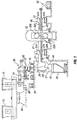
FIG. 1 is a diagrammatical side view of a twin roll caster plant shown operation with the presently disclosed method; -
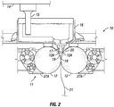
FIG. 2 is a partial sectional view through the casting rolls mounted in a roll cassette in the casting position of the caster ofFIG. 1 ; -
FIG. 3 is a transverse partial sectional view of the twin roll caster shown inFIGS. 1 and2 ; -
FIG. 4 is a transverse partial sectional view of a side dam unit shown in conjunction with a portion of a twin roll caster, the side dam unit forming one embodiment of the disclosed invention; -
FIG. 5 is a transverse partial sectional view of a side dam unit shown in conjunction with a portion of a twin roll caster, the side dam unit forming another embodiment of the disclosed invention; -
FIG. 6 illustrates in a front perspective view a side dam holder according to one exemplary embodiment of the present invention; -
FIG. 7 illustrates in a bottom perspective view a side dam holder ofFIG. 6 with tapered edged portions to dovetail with an adjacent side dam; -
FIG. 8A illustrates a front view of the side dam holder shown inFIG. 6 ; -
FIG. 8B is a sectional view of the side dam holder inFIG. 8A taken alongline 8B-8B; -
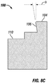
FIG. 8C is a sectional view of the side dam holder inFIG. 8A taken alongline 8C-8C; -
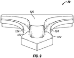
FIG. 9 illustrates a side dam with tapered edge portions to dovetail with an adjacent side dam holder; -
FIG. 10 illustrates a cross-sectional view taken transversally across side dam installed in a side dam holder according to the embodiments described in association withFIGS. 6-9 , where a dovetail joint is formed there between, the section being taken centrally across the side dam holder between side edge portions thereof (such as normal to theline 8B-8B inFIG. 8A ); -
FIG. 11 illustrates an eccentric used to induce oscillations for the oscillating side dam in accordance with an exemplary embodiment of the present invention; -
FIG. 12 illustrates a graph showing the impact on snake egg formation with oscillation of a side dam holder and adjacent side dam in accordance with the present invention; and, -
FIG. 13 illustrates a graph showing the impact on snake egg formation with oscillation of a side dam holder and adjacent side dam in accordance with the present invention. - Referring now to
FIGS. 1 and2 , in one exemplary embodiment, a twin roll caster is shown for continuously casting thin steel strip, which is one of many casters with which the side dam, side dam holder, and oscillating aspects of the side dam may be employed, as any caster employing a side dam may employ the mechanisms and methods described herein. In the embodiment shown, amain machine frame 10 stands up from the factory floor and supports aroll cassette module 11 on which a pair of counter-rotatable casting rolls 12 are mounted. The casting rolls 12 havingcasting surfaces 12A are laterally positioned to form a nip 18 there between. Theroll cassette 11 facilitates rapid movement of the casting rolls 12 as a unit from a setup position, to operative casting position, and rapid removal of the casting rolls from the casting position when the casting rolls are to be replaced. The configuration of the roll cassette may be as desired, so long as it performs that function of facilitating movement and positioning of the casting rolls 12 between the set up position and the operative casting position. - Molten metal is supplied from a
ladle 13 through a metal delivery system, such as amovable tundish 14 and a transition piece ordistributor 16. From thedistributor 16, the molten metal flows to at least onemetal delivery nozzle 17, also called core nozzle, positioned between the casting rolls 12 above thenip 18. Molten metal discharged from the delivery nozzle ornozzles 17 forms a castingpool 19 of molten metal supported on the casting surfaces 12A of the casting rolls 12 above thenip 18. This castingpool 19 is confined at the end portions of the casting rolls 12 by a pair of side closures or confining plate side dams 20 (shown in dotted line inFIG. 2 ). The upper surface of the casting pool 19 (generally referred to as the "meniscus" level) typically rise above the bottom portion of thedelivery nozzle 17 so that the lower part of thedelivery nozzle 17 is immersed in the castingpool 19. The casting area above the castingpool 19 provides the addition of a protective atmosphere to inhibit oxidation of the molten metal before casting. - The
ladle 13 typically is of a conventional construction supported on arotating turret 40. For metal delivery, theladle 13 is positioned above amovable tundish 14 in the casting position as shown inFIG. 1 to deliver molten metal tomovable tundish 14. Themovable tundish 14 may be positioned on atundish car 66 capable of transferring the tundish from a heating station (not shown), where the tundish is heated to near a casting temperature, to the casting position. A tundish guide, such as rails, may be positioned beneath thetundish car 66 to enable moving themovable tundish 14 from the heating station to the casting position. Anoverflow container 38 may be provided beneath themovable tundish 14 to receive molten material that may spill from the tundish. As shown inFIG. 1 , theoverflow container 38 may be movable onrails 39 or another guide such that theoverflow container 38 may be placed beneath themovable tundish 14 as desired in casting locations. - The
movable tundish 14 may be fitted with aslide gate 25, actuable by a servo mechanism, to allow molten metal to flow from thetundish 14 through theslide gate 25, and then through arefractory outlet shroud 15 to a transition piece ordistributor 16 in the casting position. From thedistributor 16, the molten metal flows to thedelivery nozzle 17 positioned between the casting rolls 12 above thenip 18. - The casting rolls 12 are internally water cooled so that as the casting rolls 12 are counter-rotated, shells solidify on the casting surfaces 12A as the casting surfaces 12A rotate into contact with and through the casting
pool 19 with each revolution of the casting rolls 12. The shells are brought together at thenip 18 between the casting rolls 12 to produce a solidified thincast strip product 21 delivered downwardly from thenip 18. The gap between the casting rolls is such as to maintain separation between the solidified shells at the nip so that semi-solid metal is present sandwiched between the shells through the nip, and delivered downwardly as part of the strip below the nip. -
FIG. 1 shows the twin roll caster producing thethin strip 21, which passes from the casting rolls across a guide table 30 to apinch roll stand 31, comprising pinch rolls 31A. Upon exiting the pinch roll stand 31 the thin strip passes through ahot rolling mill 32, comprising a pair of work rolls 32A, and backup rolls 32B capable of hot rolling the strip delivered from the casting rolls. In thehot rolling mill 32, the strip is hot rolled to reduce the strip to a desired thickness, improve the strip surface, and improve the strip flatness. The work rolls 32A have work surfaces relating to the desired strip profile across the work rolls. The hot rolled strip then passes onto a run-out table 33, where it may be cooled by contact with a coolant, such as water, supplied viawater jets 90 or other suitable means, and by convection and radiation. In any event, the hot rolled strip may then pass through a second pinch roll stand 91 havingrollers 91A to provide tension on the strip, and then to acoiler 92. The thickness of strip may be typically between about 0.3 and 2.0 millimeters in thickness after hot rolling. - At the start of the casting campaign, a short length of imperfect strip is typically produced as casting conditions stabilize. After continuous casting is established, the casting rolls 12 are moved apart slightly and then brought together again to cause the leading end of the thin strip to break away forming a clean head end for the following strip to cast. The imperfect material drops into a
scrap receptacle 26, which is movable on a scrap receptacle guide. Thescrap receptacle 26 is located in a scrap receiving position beneath the caster and forms part of a sealedenclosure 27 as described below. Theenclosure 27 is typically water cooled. At this time, a water-cooledapron 28 that normally hangs downwardly from apivot 29 to one side in theenclosure 27 is swung into position to guide the clean end of thestrip 21 onto the guide table 30 and feed thestrip 21 through thepinch roll stand 31. Theapron 28 is then retracted back to the hanging position to allow thestrip 21 to hang in a loop beneath the casting rolls inenclosure 27 before the strip passes to the guide table 30 where it engages a succession of guide rollers. - The sealed
enclosure 27 is formed by a number of separate wall sections that fit together with seal connections to form a continuous enclosure that permits control of the atmosphere within the enclosure. Additionally, thescrap receptacle 26 may be capable of attaching with theenclosure 27 so that the enclosure is capable of supporting a protective atmosphere immediately beneath the casting rolls 12 in the casting position. Theenclosure 27 includes an opening in the lower portion of the enclosure,lower enclosure portion 44, providing an outlet for scrap to pass from theenclosure 27 into thescrap receptacle 26 in the scrap receiving position. Thelower enclosure portion 44 may extend downwardly as a part of theenclosure 27, the opening being positioned above thescrap receptacle 26 in the scrap receiving position. As used in the specification and claims herein, "seal", "sealed", "sealing", and "sealingly" in reference to thescrap receptacle 26,enclosure 27, and related features may not be completely sealed so as to prevent atmospheric leakage, but rather usually provides a less than perfect seal appropriate to allow control and support of the atmosphere within the enclosure as desired with some tolerable leakage. - A
rim portion 45 may surround the opening of thelower enclosure portion 44 and may be movably positioned above the scrap receptacle, capable of sealingly engaging and/or attaching to thescrap receptacle 26 in the scrap receiving position. Therim portion 45 may be movable between a sealing position in which the rim portion engages the scrap receptacle, and a clearance position in which therim portion 45 is disengaged from the scrap receptacle. Alternately, the caster or the scrap receptacle may include a lifting mechanism to raise the scrap receptacle into sealing engagement with therim portion 45 of the enclosure, and then lower the scrap receptacle into the clearance position. When sealed, theenclosure 27 andscrap receptacle 26 are filled with a desired gas, such as nitrogen, to reduce the amount of oxygen in the enclosure and provide a protective atmosphere for thestrip 21. - The
enclosure 27 may include anupper collar portion 27A supporting a protective atmosphere immediately beneath the casting rolls in the casting position. When the casting rolls 12 are in the casting position, the upper collar portion is moved to the extended position closing the space between a housing portion adjacent the casting rolls 12, as shown inFIG. 2 , and theenclosure 27. The upper collar portion may be provided within or adjacent theenclosure 27 and adjacent the casting rolls, and may be moved by a plurality of actuators (not shown) such as servo-mechanisms, hydraulic mechanisms, pneumatic mechanisms, and rotating actuators. - There is shown in
FIG. 3 a pair ofdelivery nozzles 17 each made of a refractory material such as zirconia graphite, alumina graphite or any other suitable material. The twodelivery nozzles 17 may be positioned end-to-end as shown inFIG. 3 . It must be understood that one or more than twodelivery nozzles 17 may be used in any different sizes and shapes if desired. The delivery nozzles 17 need not be substantially the same in size and shape, although generally such is desirable to facilitate fabrication and installation. Twodelivery nozzles 17 may be each capable of moving independently of the other above the casting rolls 12. - Typically where two
delivery nozzles 17 are used thenozzles 17 are disposed and supported in end-to-end relationship as shown inFIG. 3 along the nip 18 (seeFIG. 2 ) withgap 34 there between, so that eachdelivery nozzle 17 can be moved inwardly toward the other during a casting campaign as explained below. It must be understood, however, that any desired number ofdelivery nozzles 17 may be used. Two delivery nozzles may be used as described below, or include any additional number of nozzle disposed there between. For example, there may be a central nozzle segment adjacent to outer nozzle segments on either side. - Each
delivery nozzle 17 may be formed in one piece or multiple pieces. As shown, eachnozzle 17 includes anend wall 23 positioned nearest a confiningside dam 20 as explained below. Eachend wall 23 may be configured to achieve a particular desired flow pattern of molten metal flow into the casting pool, particularly in the triple point region between the casting rolls 12 and therespective side dam 20. - The
side dams 20 are made from a refractory material such as zirconia graphite, graphite alumina, boron nitride, boron nitride-zirconia, or other suitable composites. Theside dams 20 have a face surface capable of physical contact with the casting rolls and molten metal in the casting pool. - A pair of carriage assemblies, generally indicated at 94, are provided to position both the
side dams 20 and thedelivery nozzles 17. As illustrated, the twin roll caster is generally symmetrical, although such is not required. Referring toFIG. 3 , onecarriage assembly 94 is illustrated and described below, with the other carriage assembly being generally similar. Eachcarriage assembly 94 is disposed at one end of the pair of casting rolls 12. Eachcarriage assembly 94 may be mounted fixed relative to themachine frame 10, or may be moveable axially toward and away from the casting rolls 12 to enable the spacing between thecarriage assembly 94 and the casting rolls 12 to be adjusted. Thecarriage assemblies 94 may be preset in final position before a casting campaign to suit the width of the casting rolls 12 and strip to be cast, or the position of thecarriage assemblies 94 may be adjusted as desired during a casting campaign. Thecarriage assemblies 94 may be positioned one at each end of the roll assembly and moveable toward and away from one another to enable the spacing between them to be adjusted. Thecarriage assemblies 94 can be preset before a casting operation according to the width of the casting rolls and to allow quick roll changes for differing strip widths. Thecarriage assemblies 94 may be positioned so as to extend horizontally above the casting rolls with thenozzles 17 positioned beneath thedistributor 16 in the casting position and at a central position to receive the molten metal. For example thecarriage assembly 94 may be positioned from tracks (not shown) on themachine frame 10, which may be mounted by clamps or any other suitable mechanism. Alternatively, thecarriage assembly 94 may be supported by its own support structure relative to the casting rolls 12. - Referring to one exemplary embodiment in
FIG. 4 , and to another exemplary embodiment inFIG. 5 , eachcarriage assembly 94 includes asupport frame 300, anactuator 310, and acore nozzle support 370.Actuator 310 is moveably connected to thesupport frame 300 and engages (that is, actuates) both thedelivery nozzles 17 and theside dam holder 100 for selective movement of both thedelivery nozzles 17 andside dam 20.Actuator 310 is capable of positioning both thedelivery nozzles 17 and theside dam 20, and is also capable of cyclically varying the axial force of the side dams. -
Actuator 310 is a hydraulic cylinder. It must be understood, however, thatactuator 310 may be any suitable drive mechanism suitable to move and adjustdelivery nozzles 17 and suitable to position theside dam holder 100 to bring theadjacent side dam 20 into engagement with the casting rolls 12 to confine the castingpool 19 formed on the casting surfaces 12A during a casting operation (seeFIG. 2 ). Such a suitable drive mechanism, for example, may be a servo mechanism, a screw jack drive operated by electric motor, a pneumatic mechanism, a gear mechanisms, a cog, a drive chain mechanism, a pulley and cable mechanism, a drive screw mechanism, a jack actuator, a rack and pinion mechanism, an electro-mechanical actuator, an electric motor, a linear actuator, a rotating actuator, or any other suitable device. Eachside dam 20 is mounted with an adjacentside dam holder 100, and movable together withactuator 310, such as a servo mechanism, to bring theside dam 20 into engagement with an end portion of the casting rolls.Linear bearings 312 are employed to slidably connectcarriage 94 generally to thenozzle 17, and more specifically, to slidably connectsupport frame 300 to acore nozzle plate 320, which is directly or indirectly attached tonozzle 17. It is noted that this slidable connection is located above the side dam and above the side dam oscillating components. - A side
dam position sensor 112 senses the position of theside dam 20. The sidedam position sensor 112 is a linear displacement sensor to measure the actual change in position of theside dam holder 100 relative to thesupport frame 300. The sidedam position sensor 112 may be any sensor suitable to indicate any parameter representative of a position of theside dam 20. For example, the sidedam position sensor 112 may be a linear variable displacement transducer to respond to the extension of theactuator 310 to provide signals indicative of position of theside dam 20, or an optical imaging device for tracking the position of theside dam 20 or any other suitable device for determining the location of theside dam 20. The sidedam position sensor 112 may also or alternatively include a force sensor, or load cell for determining the force urging theside dam 20 against the casting rolls 12 and providing electrical signals indicative of the force urging the side dam against the casting rolls. Alternatively, a load cell may be placedadjacent oscillation plate 210. In any case,actuator 310 andsensor 112 may be connected into a control system with a circuit receiving control signals determined by the movement of the side dams. During a casting campaign the control system of the twin roll caster is capable of actuating theactuator 310 to vary the apply force on theside dams 20 against the end portions of the casting rolls 12 along the axis of the two casting rolls. The control system may receive position or force information from thesensors 112 or from direct feedback of theactuator 310. - As explained above and illustrated in
FIGS. 6 to 8C , each side dam 20 (shownFIGS. 4 ,5 , and9 ) is mounted within an adjacent aside dam holder 100.Side dam holder 100 has a thickness extending between opposing sides, oneside 102 being configured to receive a side dam. The oneside 102 includes sidedam mounting projection 104, each projection is tapered along aside edge portion 106 to dovetail with the tapered side edge portions of an adjacent side dam to assemble the side dam within the side dam holder and into an installed position. The taperedside edge portions 106 shown form inner side edges of eachprojection 104, that is, each forms a side edge that faces a lateral center of the side dam holder. Instead, it is appreciated that in other variations the tapered side edge portion for dovetailing with a corresponding tapered side edge on a side dam may instead form anouter side edge 108 of eachprojection 104. Each projection extends lengthwise at least a partial height and up to the full height of the side dam holder, the height extending from abottom 200 of the side dam holder to a top 202 of the side dam holder. In the exemplary embodiment shown, eachprojection 104 extends predominantly the full height of theside dam holder 100. By virtue of using a dovetail attachment between the side dam and the side dam holder, a more durable and tighter fitting attachment is achieved to better hold the adjacent side dam in position while the side dam and side dam holder are laterally oscillated together. With specific reference toFIG. 8C , it is shown thatside edge portions 106 of theside dam holder 100 to dovetail with the adjacent side dam may be tapered by angle θ at or between 3 and 15 degrees. The tapered edge portions may be continuous through the contact internal surface of the side dam holder. - The tapered edge portions on the side dams allow the side dam holder to hold the adjacent side dam in position. An
exemplary side dam 20 is shown inFIG. 9 configured to matingly dovetail with the side dam holder shown previously, theside dam 20 having a generally triangular shape similar to the side dam holder, having arcuate lateral sides 124.Side dam 20 also includes acentral projection 120 extending outwardly from a back side of the side dam, the back side being arranged opposite a casting roll side of the side dam and of the side dam thickness, the casting roll side including refractory for engaging the casting rolls and forming the casting pool of molten steel. Opposing lateral sides ofprojection 120 include tapered side edges 122. It is appreciated that even though both tapered side edges 122 are arranged along asingle projection 120, multiple projections may be provided where separate tapered side edges 122 are arranged along different projections. It is noted that dovetail joints can accommodate projections of different sizes. Also, each side dam holder may accommodate side dams of different thicknesses. For example, a side dam holder having a dovetail design can accept different side dams each having a thickness of 27, 40, and 44 millimeters (mm) respectively. In either case, the tapered edge portions on the side dam and side dam holder may be continuous or intermittent along the edge portions of the side dam holder and side dam, and need not be conversely identical. It is sufficient for the tapered edge portions on the side dam holder and side dam be such so as to hold the side dam in casting position during the casting campaign. With reference toFIG. 10 ,side dam 20 is shown mounted ontoside dam holder 100 by way of a dovetail joint formed there between. - Optionally, an air gap is arranged between the side dam and the side dam holder. This provides improved insulative properties to protect both protect the side dam holder and to prevent heat loss from the casting pool through the side dam. In the exemplary embodiment shown in
FIGS. 6 ,8A ,8B , and10 , arecess 110 is arranged withinside 102 between opposingprojections 104 to provide the air gap. However, other variations may be employed to achieve this air gap. For example, alternatively or additionally, a like recess may be arranged centrally within the backside of the side dam. In certain embodiments, this air gap extends along at least 50% and in other variations 85% to 90% of the area between the side dam and side dam holder. In certain instances, the depth ofrecess 110 and/or the corresponding air gap is 3 mm to 10 mm, and 5 mm in other certain instances. - In any case, during casting, the side dams move inwardly against the ferrostatic force of the casting pool, are laterally oscillated, and are optionally moved upward against the casting rolls. It is appreciated that vertical movement may assist in reducing the formation, severity, and frequency of skulls. In an exemplary embodiment configured to provide both lateral oscillations and vertical movement,
FIG. 4 show side dam 20,side dam holder 100,oscillation plate 210, fixedplate 220,vertical lift plate 230, andupper wedge 240, andlower wedge 250.Side dam 10 is supported byside dam holder 100.Oscillation plate 210 is operably connected to the side dam holder, and provides for the lateral oscillation of the side dam holders and adjacent side dams. Oscillations are generated by an oscillating mechanism comprising an eccentric connected to a rotational shaft driven by a motor. An eccentric may form an eccentric rotary shaft or a disc or wheel mounted eccentrically on a rotational shaft in order to transform rotation into backward-and-forward motion, such as by way of a cam. An eccentric may take any other form that transforms rotation into backward-and-forward motion. As for the motor, and motor may be employed, such as any electric motor or internal combustion engine. In other variations, a the oscillating mechanism comprises a cylinder arranged to extend and retract in a lateral direction. Each side dam may be laterally oscillated between 2 and 50 hertz during a casting campaign, or may be laterally oscillated between 2 and 30 hertz during the casting campaign.Hydraulic cylinder 350,vertical lift plate 230,upper wedge 240 andlower wedge 250 provide for the optional vertical movement of the side dam holders and adjacent side dams during the casting campaign. Each side dam holder and adjacent side dam may be vertically moved at least 100 µm during the casting campaign. Alternatively, each side dam holder and adjacent side dam may be vertically moved between 3 and 15 millimeters during the casting campaign. - In the embodiment shown in
FIG. 5 , a portion of the caster is shown comprising a carriage that is configured to oscillate a side dam, which incorporates dovetailed attachment of the side dam to the side dam holder. In this exemplary embodiment, the side dam is not configured to move vertically. Therefore, oscillation of the side dam is limited to lateral oscillations. While this may be achieved using other oscillating mechanisms, in this embodiment, lateral-only oscillations are achieved by an oscillating mechanism comprising is amotor 330 operating in cooperation with an eccentric. In this variation, the motor is a hydraulic motor operably connected to a rotational (drive)shaft 332. Anencoder 334 is arranged along the length of therotational shaft 332 to track the rotational position of the shaft. In an effort to control and limit the oscillatory movement of theside dam holder 100 andside dam 20 in a substantially lateral direction, a plurality of plain,linear bearings 336 slidably attach the oscillation plate to the carriage. A fixed attachment is provided between theoscillation plate 210 and theside dam holder 100, which are spaced apart in this embodiment to better protect the oscillation plate from heat exposure. Also, theoscillation plate 210 is water cooled by way of awater cooling system 338 to further control temperatures. With additional reference toFIG. 11 , the eccentric comprises acylindrical member 340 mounted non-axially on therotational shaft 332. In other words, the central axis A340 of thecylindrical member 340 is offset by distance D from the rotational axis A332 of therotational shaft 332. By doing so, the annular extent of thecylindrical member 340 induces lateral oscillations when engaging horizontal sides S342 of anoblong opening 342 in theoscillation plate 210. In particular, theoblong opening 342 is narrowest between opposing horizontal sides S342 and longest between top T342 and bottom B342. In operation,cylindrical member 340 engages horizontal sides S342 to cause lateral oscillations while remaining spaced apart from each of the top T342 and bottom B342 to avoid any movement in the vertical direction and any vertical oscillations. It is appreciated that theoblong opening 342 may form a cutout in theoscillation plate 210 or may form an oblong opening in a bushing or other member attached to a larger opening formed in theoscillation plate 210. By using a motor with an eccentric, oscillating frequency may be adjusted, in addition to adjusting the stroke (amplitude) of the oscillations. Additionally, the generation of any desired oscillating frequency may be more reliably generated. - As illustrated in
FIGS. 12 and13 , lateral oscillation of the side dam holder and adjacent side dam allows for substantial reduction or elimination of snake eggs in the strip. As show inFIG. 12 , no snakes eggs were seen when the side dam holders and adjacent side dams were laterally oscillated in this embodiment. However, when lateral oscillation of the side dam holders and adjacent side dams was stopped, snakes eggs were found to immediately be observed. And once the side dam holders and adjacent side dams were laterally oscillated again, snake eggs were once again immediately reduced, if not eliminated. As shown, lateral oscillation of the side dam holder and adjacent side dam allows for the prevention of snake eggs formation. - In further evaluating the impact of laterally oscillating the side dams, after observation a plurality of castings, in forming a single coil of cast strip, the occurrence of snake eggs reduced from 15.22 on average per coil using non-oscillating side dams to 5.57 on average per coil using laterally oscillating side dams. The severity of each snake egg was also reduced on average by 45%.
- Additionally, by oscillating the side dam, the molten metal supplied to the caster may be reduced, which reduces manufacturing costs by eliminating the need to generate and supply additional heat to the molten steel. In certain instances, a reduction of 25 degrees F has been successfully employed when producing cast strip using oscillating side dams, which is a 10 to 12 % reduction in temperature relative to the liquid's temperature.
Claims (15)
- An apparatus for continuous casting metal strip reducing snake eggs comprising:a. a pair of counter rotating casting rolls (12), each casting roll (12) less than 800 millimeters in diameter and positioned to form a nip (11) there between through which thin strip can be cast;b. a metal delivery system (14) disposed above the nip (11) and capable of discharging molten metal to form a casting pool (19) supported on the casting rolls (12);c. a pair of side dam holders (100) and a pair of side dams (20) assembled adjacent each end portion of the casting rolls (12), and each side dam (20) adapted to confine the casting pool (19) of molten metal supported on casting surfaces (12A) of the casting rolls (12) above the nip (11); andd. an oscillation mechanism (210) adapted to cause lateral oscillation of each side dam (20) and side dam holder (100) together at a frequency between 2 and 50 hertz and with an amplitude between 100 µm and 2000 µm during a casting campaign;e. characterised in that each side dam holder (100) is tapered along edge portions (106) to dovetail with edge portions of an adjacent side dam (20) assembled in position; and in that each side dam (20) is made from a refractory material.
- An apparatus for continuous casting metal strip as claimed in claim 1 where the oscillation mechanism (210) is adapted to cause lateral oscillation of each side dam holder (100) and adjacent side dam (20) at a frequency between 2 and 30 hertz and with an amplitude between 100 µm and 2000 µm, typically at a frequency between 2 and 50 hertz and with an amplitude between 100 µm and 1250 µm, and typically at a frequency between 2 and 30 hertz and with an amplitude between 100 µm and 1250 µm.
- An apparatus for continuous casting metal strip as claimed in claims 1 or claim 2, wherein the edge portions (106) of each side dam holder (100) tapered to dovetail with the adjacent side dam are tapered at between 3 and 15 degrees.
- An apparatus for continuous casting metal strip as claimed in any one of the preceding claims further comprising a mechanism (360, 230, 240, 250) providing vertical movement of each side dam holder (100) and adjacent side dam (20) of at least 100 µm per hour during the casting campaign.
- An apparatus for continuous casting metal strip as claimed in any one of claims 1 to 3 further comprising a mechanism (360, 230, 240, 250) providing vertical movement of each side dam holder (100) and adjacent side dam (20) by between 3 and 15 millimeters during the casting campaign.
- A method of continuously casting metal strip comprising the steps of:(a) assembling a pair of counter-rotating casting rolls (12) laterally forming a nip (11) between circumferential casting surfaces (12A) of the casting rolls (12) through which metal strip can be cast;(b) assembling a pair of side dam holders (100) and a pair of side dams (12) adjacent each end portion of the casting rolls (12), and with each side dam (20) adapted to confine a casting pool (19) of molten metal supported on casting surfaces (12A) of the casting rolls (12) above the nip (11);(c) assembling a metal delivery system (14) above the casting rolls (12) delivering molten metal to form a casting pool (19) supported on the casting surfaces (12A) of the casting rolls (12) above the nip (11) and confined by the side dams (20) at each end portion of casting rolls (12);(d) laterally oscillating each side dam holder (100) and adjacent side dam (20) at a frequency between 2 and 50 hertz with an amplitude between 100 µm and 2000 µm during a casting campaign; and(e) counter-rotating the casting rolls (12) such that the casting surfaces (12A) of the casting rolls (12) each travel inwardly toward the nip (11) to produce a cast strip downwardly from the nip (11);
characterised in that each side dam holder (100) is tapered along edge portions (106) to dovetail with edge portions of adjacent side dam (20) assembled in position; and in that each side dam (20) is made from a refractory material. - A method of continuously casting metal strip as claimed in claim 6 further comprising laterally oscillating each side dam holder (100) and adjacent side dam (20) at a frequency between 2 and 30 hertz with an amplitude between 100 µm and 2000 µm during a casting campaign, typically at a frequency between 2 and 50 hertz with an amplitude between 100 µm and 1250 µm during a casting campaign, and typically at a frequency between 2 and 30 hertz with an amplitude between 100 µm and 1250 µm during a casting campaign.
- A method of continuously casting metal strip as claimed in claim 6 or claim 7 further comprising vertically moving each side dam holder (100) and adjacent side dam (20) at least 100 µm per hour during a casting campaign.
- A method of continuously casting metal strip as claimed in claim 6 or claim 7 further comprising vertically moving each side dam holder (100) and adjacent side dam (20) between 3 and 15 millimeters during a casting campaign.
- A side dam holder (100) for continuously casting metal strip characterised by edge portions (106) adapted to dovetail with and support an adjacent side dam (20) by tapers between 3 and 15 degrees to hold the adjacent side dam (20) and adapted to move with the side dam holder (100).
- A side dam assembly for continuous casting metal strip comprising:(a) a pair of side dams (20) adjacent to end portions of a pair of counter-rotating casting rolls (12), each casting roll (12) with less than 800 millimeters in diameter and positioned to form a nip (11) there between through which thin strip can be cast, with each side dam (20) adapted to confine a casting pool (19) of molten metal supported on casting surfaces (12A) of the casting rolls (12) above the nip (11);(b) a pair of side dam holders (100), each side dam holder (100) supporting an adjacent side dam (20); and(c) an oscillation mechanism (210) adapted to cause lateral oscillation of each side dam (20) and side dam holder (100) together at a frequency between 2 and 50 hertz and with an amplitude between 100 µm and 2000 µm during a casting campaign;
characterised in that each side dam holder (100) are tapered along edge portions (106) to dovetail with edge portions of the adjacent side dam (20) assembled in position and adapted to move with the adjacent side dam (20); and in that each side dam (20) is made from a refractory material. - A side dam assembly for continuous casting metal strip as claimed in claim 11, wherein the oscillation mechanism (210) is adapted to cause lateral oscillation of each side dam (20) and side dam holder (100) together at a frequency between 2 and 30 hertz and with an amplitude between 100 µm and 2000 µm during a casting campaign, typically at a frequency between 2 and 30 hertz and with an amplitude between 100 µm and 1250 µm during a casting campaign, and typically at a frequency between 2 and 50 hertz and with an amplitude between 100 µm and 1250 µm during a casting campaign.
- A side dam assembly for continuous casting metal strip as claimed in claim 11 or claim 12, wherein the edge portions (106) of each side dam holder (100) tapered to dovetail with the adjacent side dam (20) are tapered at between 3 and 15 degrees.
- The side dam assembly for continuous casting metal strip as claimed in any one of claims 11 to 13 further comprising a mechanism (360, 230, 240, 250) providing vertical movement of each side dam holder (100) and adjacent side dam (20) of at least 100 µm per hour during the casting campaign.
- The side dam assembly for continuous casting metal strip as claimed in any one of claims 11 to 13 further comprising a mechanism (360, 230, 240, 250) providing vertical movement of each side dam holder (100) and adjacent side dam (20) by between 3 and 15 millimeters during the casting campaign.
Priority Applications (1)
| Application Number | Priority Date | Filing Date | Title |
|---|---|---|---|
| PL17840308T PL3496881T3 (en) | 2016-08-10 | 2017-08-10 | Method of thin strip casting |
Applications Claiming Priority (2)
| Application Number | Priority Date | Filing Date | Title |
|---|---|---|---|
| US201662373086P | 2016-08-10 | 2016-08-10 | |
| PCT/US2017/046373 WO2018031823A1 (en) | 2016-08-10 | 2017-08-10 | Method of thin strip casting |
Publications (3)
| Publication Number | Publication Date |
|---|---|
| EP3496881A1 EP3496881A1 (en) | 2019-06-19 |
| EP3496881A4 EP3496881A4 (en) | 2019-10-30 |
| EP3496881B1 true EP3496881B1 (en) | 2021-10-20 |
Family
ID=61163126
Family Applications (1)
| Application Number | Title | Priority Date | Filing Date |
|---|---|---|---|
| EP17840308.5A Active EP3496881B1 (en) | 2016-08-10 | 2017-08-10 | Method of thin strip casting |
Country Status (8)
| Country | Link |
|---|---|
| US (1) | US11027330B2 (en) |
| EP (1) | EP3496881B1 (en) |
| CN (1) | CN109715316B (en) |
| BR (1) | BR112019002668B1 (en) |
| MX (1) | MX2019001627A (en) |
| PL (1) | PL3496881T3 (en) |
| SA (1) | SA519401053B1 (en) |
| WO (1) | WO2018031823A1 (en) |
Family Cites Families (83)
| Publication number | Priority date | Publication date | Assignee | Title |
|---|---|---|---|---|
| GB1154264A (en) | 1967-10-10 | 1969-06-04 | Ts Kt B | A method of Manufacturing Cast-Iron Pipes and an Installation for effecting same |
| JPS6038225B2 (en) | 1977-09-12 | 1985-08-30 | ソニー株式会社 | Manufacturing method of amorphous alloy |
| JPS5564951A (en) | 1978-11-10 | 1980-05-16 | Tdk Corp | Anisotropy controlling method of magnetic thin metal strip |
| JPS5647247A (en) | 1979-09-25 | 1981-04-28 | Toshiba Corp | Production of compound superconductive wire |
| JPS56165543A (en) | 1980-05-23 | 1981-12-19 | Nippon Steel Corp | Method for continuous casting of metal |
| FR2498099A2 (en) | 1981-01-19 | 1982-07-23 | Conditionnements Aluminium Sca | METHOD FOR CONTROLLING AND REGULATING MARKET PARAMETERS OF A CONTINUOUS CASTING MACHINE OF BANDS BETWEEN CYLINDERS FOR AVOIDING COLLAGE |
| JPS57130742A (en) | 1981-02-02 | 1982-08-13 | Matsushita Electric Ind Co Ltd | Production of thin strip |
| JPS5829553A (en) | 1981-08-18 | 1983-02-21 | Nippon Steel Corp | Continuous casting installation |
| JPS5832551A (en) | 1981-08-21 | 1983-02-25 | Kawasaki Steel Corp | Method and mold for continuous casting of thin walled ingot |
| JPS58218348A (en) | 1982-06-12 | 1983-12-19 | Kawasaki Steel Corp | Continuous casting device of thin steel plate |
| JPS59153553A (en) | 1983-02-22 | 1984-09-01 | Nippon Kokan Kk <Nkk> | Horizontal continuous casting equipment of thin walled billet |
| JPS60124451A (en) | 1983-12-10 | 1985-07-03 | Sumitomo Metal Ind Ltd | Method for detecting and controlling abnormality of twin belt caster |
| JPS60170559A (en) | 1984-02-13 | 1985-09-04 | Mitsubishi Heavy Ind Ltd | Continuous casting device |
| JPS6127148A (en) | 1984-07-17 | 1986-02-06 | Sumitomo Metal Ind Ltd | Method and device for horizontal and continuous casting |
| JPS6142455A (en) | 1984-08-07 | 1986-02-28 | Sumitomo Heavy Ind Ltd | Belt type continuous casting machine |
| JPS6142454A (en) | 1984-08-07 | 1986-02-28 | Sumitomo Heavy Ind Ltd | Belt type continuous casting machine |
| JPS61140351A (en) | 1984-12-14 | 1986-06-27 | Mitsubishi Heavy Ind Ltd | Apparatus for producing thin sheet |
| JPS61172657A (en) | 1985-01-25 | 1986-08-04 | Sumitomo Heavy Ind Ltd | Belt type continuous casting machine |
| JPS61266160A (en) | 1985-05-21 | 1986-11-25 | Mitsubishi Heavy Ind Ltd | Continuous casting device for thin sheet |
| JPS61296943A (en) | 1985-06-25 | 1986-12-27 | Mitsubishi Heavy Ind Ltd | Molten steel level control device of continuous casting device for thin sheet |
| JPS61296942A (en) | 1985-06-27 | 1986-12-27 | Mitsubishi Heavy Ind Ltd | Molten steel level control device of continuous casting device for thin sheet |
| JPS6213245A (en) | 1985-07-10 | 1987-01-22 | Furukawa Electric Co Ltd:The | Production of thin composite sheet for acoustic apparatus |
| JPS6245456A (en) * | 1985-08-23 | 1987-02-27 | Ishikawajima Harima Heavy Ind Co Ltd | Twin roll type continuous casting machine |
| US4678023A (en) | 1985-12-24 | 1987-07-07 | Aluminum Company Of America | Closed loop delivery gauge control in roll casting |
| JPS62259644A (en) | 1986-05-02 | 1987-11-12 | Kawasaki Steel Corp | Method and apparatus for producing rapidly cooled sheet metal having excellent end face |
| JPS62259642A (en) | 1986-05-02 | 1987-11-12 | Mitsubishi Heavy Ind Ltd | Continuous casting apparatus for strip |
| JPS62270252A (en) | 1986-05-19 | 1987-11-24 | Mitsubishi Heavy Ind Ltd | Continuous casting method for strip |
| US4727927A (en) | 1987-01-20 | 1988-03-01 | Hunter Engineering Company, Inc. | Casting machine control |
| JPH0716767B2 (en) | 1987-01-23 | 1995-03-01 | 新日本製鐵株式会社 | Method and apparatus for continuous casting of metal ribbon |
| JPS6453740A (en) | 1987-08-25 | 1989-03-01 | Hitachi Ltd | Continuous casting machine |
| JPH01266946A (en) | 1988-04-15 | 1989-10-24 | Nippon Steel Corp | Magnetic field introducing twin roll type strip continuous casting method |
| JPH01273655A (en) | 1988-04-26 | 1989-11-01 | Kawasaki Steel Corp | Method for continuously casting strip and continuous casting machine |
| JPH0829399B2 (en) | 1988-06-02 | 1996-03-27 | 新日本製鐵株式会社 | Continuous casting method for metal ribbon |
| JPH0225248A (en) | 1988-07-14 | 1990-01-26 | Kawasaki Steel Corp | Production of rapidly cooled thin strip |
| JP2649066B2 (en) | 1988-08-03 | 1997-09-03 | 新日本製鐵株式会社 | Twin roll thin plate continuous casting method |
| JPH082481B2 (en) | 1988-08-10 | 1996-01-17 | 日新製鋼株式会社 | Thin plate continuous casting machine |
| US4940077A (en) | 1988-11-21 | 1990-07-10 | Reynolds Metals Company | Method of and apparatus for direct metal strip casting |
| JPH02155543A (en) | 1988-12-09 | 1990-06-14 | Hitachi Ltd | Apparatus for continuously casting cast strip |
| GB8910906D0 (en) | 1989-05-12 | 1989-06-28 | Davy Distington Ltd | Rotary strip caster edge containment |
| FR2648063B1 (en) | 1989-06-12 | 1994-03-18 | Irsid | METHOD AND DEVICE FOR VIBRATION OF A CONTINUOUS CASTING LINGOTIERE OF METALS |
| JPH0360849A (en) | 1989-07-31 | 1991-03-15 | Hitachi Ltd | Thin plate continuous casting equipment |
| AU646071B2 (en) | 1990-08-03 | 1994-02-03 | Davy Mckee (Poole) Limited | Twin roll casting |
| GB2250461B (en) | 1990-11-14 | 1994-06-29 | Ishikawajima Harima Heavy Ind | Strip casting |
| JPH04197559A (en) | 1990-11-27 | 1992-07-17 | Nkk Corp | Continuous steel casting method |
| FR2670413B1 (en) | 1990-12-17 | 1993-04-09 | Usinor Sacilor | CONTINUOUS CASTING DEVICE FOR THIN STRIPS OF METAL, ESPECIALLY STEEL. |
| JPH07106434B2 (en) | 1991-03-15 | 1995-11-15 | 新日本製鐵株式会社 | Continuous casting method for metal ribbon |
| KR920019450A (en) | 1991-04-10 | 1992-11-19 | 라우에너 엔지니어링 악티엔게젤샤프트 | Roll casting method |
| CA2077145A1 (en) | 1991-08-29 | 1993-03-01 | Julian Szekely | Method and apparatus for the magnetic stirring of molten metal in a twin roll caster |
| JPH0749140B2 (en) | 1992-02-17 | 1995-05-31 | 三菱重工業株式会社 | Twin-drum type continuous casting machine |
| MY111637A (en) | 1992-11-30 | 2000-10-31 | Bhp Steel Jla Pty Ltd | Metal strip casting |
| DE4240849A1 (en) | 1992-12-04 | 1994-06-09 | Didier Werke Ag | Process for forming a separation gap, especially in metallurgy |
| AUPM589894A0 (en) | 1994-05-27 | 1994-06-23 | Bhp Steel (Jla) Pty Limited | Metal strip casting |
| FR2721844B1 (en) | 1994-06-30 | 1996-08-30 | Usinor Sacilor | METHOD AND DEVICE FOR CONTINUOUSLY CASTING THIN METAL PRODUCTS BETWEEN CYLINDERS |
| AU2783695A (en) | 1994-07-08 | 1996-02-09 | Ipsco Inc. | Stationary mold for use with twin-roll caster |
| WO1996001708A1 (en) | 1994-07-08 | 1996-01-25 | Ipsco Inc. | Twin-roll caster and rolling mill for use therewith |
| AUPN426095A0 (en) | 1995-07-19 | 1995-08-10 | Bhp Steel (Jla) Pty Limited | Method and apparatus for giving vibration to molten metal in twin roll continuous casting machine |
| FR2737859B1 (en) * | 1995-08-18 | 1997-09-12 | Usinor Sacilor | SUPPORT DEVICE FOR A SIDE FACE OF A CONTINUOUS CASTING PLANT OF METAL BANDS BETWEEN CYLINDERS |
| US6585032B2 (en) | 1996-06-07 | 2003-07-01 | Mannesmann Ag | Strip casting plant |
| PL184229B1 (en) | 1996-06-07 | 2002-09-30 | Mannesmann Ag | Metal strip casting machine |
| JP3594740B2 (en) | 1996-07-24 | 2004-12-02 | 株式会社日立情報システムズ | Homepage management system |
| DE19651324C2 (en) | 1996-12-11 | 1999-03-18 | Schloemann Siemag Ag | Method and device for producing coated continuous cast products |
| FR2757790B1 (en) | 1996-12-31 | 1999-01-22 | Usinor | PROCESS FOR CONTINUOUS CASTING OF THIN METAL STRIPS BETWEEN TWO CYLINDERS, AND INSTALLATION FOR IMPLEMENTING SAME |
| JPH1157746A (en) | 1997-08-22 | 1999-03-02 | Mitsubishi Chem Corp | Treatment method for selenium-containing liquid |
| KR100368276B1 (en) | 1997-12-20 | 2003-03-17 | 주식회사 포스코 | Method and apparatus for lubricating edge dam in twin roll type continuous strip caster |
| US7073565B2 (en) | 1999-02-05 | 2006-07-11 | Castrip, Llc | Casting steel strip |
| AUPQ007199A0 (en) * | 1999-05-03 | 1999-05-27 | Bhp Steel (Jla) Pty Limited | Strip casting apparatus |
| CH691574A5 (en) | 1999-09-24 | 2001-08-31 | Main Man Inspiration Ag | The strip casting machine for producing a metal strip. |
| US6860317B2 (en) | 2000-10-31 | 2005-03-01 | Korea Atomic Energy Research Institute | Method and apparatus for producing uranium foil and uranium foil produced thereby |
| KR100388808B1 (en) | 2000-10-31 | 2003-06-25 | 한국전력공사 | Uranium foil having fine grains solidified rapidly from melt by cooling roll directly, and the fabrication apparatus and the fabrication process |
| DE10056916A1 (en) | 2000-11-16 | 2002-05-23 | Sms Demag Ag | Process for continuously casting a steel strip comprises passing the strip between casting rollers with front sides having adjustable sealing elements which move along a vertical plane in the casting direction |
| IL144972A0 (en) | 2001-08-19 | 2002-06-30 | Nat Diversified Ind Aust Pty L | Continuous casting of metal sheets and bands |
| ITMI20021505A1 (en) | 2002-07-10 | 2004-01-12 | Danieli Off Mecc | ROLLER SUPPORT DEVICE FOR CONTINUOUS CASTING OF METAL TAPE |
| CH696756A5 (en) | 2003-10-08 | 2007-11-30 | Main Man Inspiration Ag | A method of generating oscillating movements of side seals of a strip casting machine for producing a metal strip and a device for performing the method. |
| US7191819B2 (en) * | 2004-12-07 | 2007-03-20 | Nucor Corporation | Continuously casting steel strip |
| US7503375B2 (en) | 2006-05-19 | 2009-03-17 | Nucor Corporation | Method and apparatus for continuously casting thin strip |
| US7650925B2 (en) | 2006-08-28 | 2010-01-26 | Nucor Corporation | Identifying and reducing causes of defects in thin cast strip |
| DE102008010688B4 (en) | 2008-02-22 | 2019-03-28 | Outokumpu Nirosta Gmbh | Method and two-roll casting machine for producing cast from a molten metal strip |
| DE102008010689B4 (en) | 2008-02-22 | 2018-10-31 | Outokumpu Nirosta Gmbh | Two-roll casting machine for producing cast from a molten metal strip |
| JP2009208140A (en) | 2008-03-06 | 2009-09-17 | Fujifilm Corp | Manufacturing method of aluminum alloy sheet for planographic printing plate, aluminum alloy sheet for planographic printing plate and support for planographic printing plate manufactured by the method |
| WO2010051590A1 (en) | 2008-11-06 | 2010-05-14 | Bluescope Steel Limited | Strip casting apparatus with improved side dam force control |
| CN102712035B (en) | 2009-10-30 | 2015-07-15 | 纽科尔公司 | Method and apparatus for controlling variable shell thickness in cast strip |
| KR101264232B1 (en) | 2009-12-28 | 2013-05-14 | 주식회사 포스코 | Apparatus and method for controlling horizontal oscillation of edge dam in twin roll strip caster |
| US20140262121A1 (en) | 2013-03-15 | 2014-09-18 | Nucor Corporation | Method of thin strip casting |
-
2017
- 2017-08-10 PL PL17840308T patent/PL3496881T3/en unknown
- 2017-08-10 CN CN201780056902.9A patent/CN109715316B/en active Active
- 2017-08-10 MX MX2019001627A patent/MX2019001627A/en unknown
- 2017-08-10 EP EP17840308.5A patent/EP3496881B1/en active Active
- 2017-08-10 US US16/323,976 patent/US11027330B2/en active Active
- 2017-08-10 BR BR112019002668-1A patent/BR112019002668B1/en active IP Right Grant
- 2017-08-10 WO PCT/US2017/046373 patent/WO2018031823A1/en not_active Ceased
-
2019
- 2019-02-07 SA SA519401053A patent/SA519401053B1/en unknown
Non-Patent Citations (1)
| Title |
|---|
| None * |
Also Published As
| Publication number | Publication date |
|---|---|
| EP3496881A1 (en) | 2019-06-19 |
| BR112019002668B1 (en) | 2022-07-26 |
| EP3496881A4 (en) | 2019-10-30 |
| CN109715316B (en) | 2021-09-21 |
| BR112019002668A2 (en) | 2019-05-28 |
| CN109715316A (en) | 2019-05-03 |
| PL3496881T3 (en) | 2022-01-17 |
| US20190210098A1 (en) | 2019-07-11 |
| US11027330B2 (en) | 2021-06-08 |
| MX2019001627A (en) | 2019-09-04 |
| WO2018031823A1 (en) | 2018-02-15 |
| SA519401053B1 (en) | 2022-04-20 |
Similar Documents
| Publication | Publication Date | Title |
|---|---|---|
| CN102131600B (en) | Strip casting method for controlling edge quality and apparatus therefor | |
| AU767038B2 (en) | Strip casting apparatus | |
| US20140261905A1 (en) | Method of thin strip casting | |
| US8499820B2 (en) | Strip casting apparatus with independent delivery nozzle and side dam actuators | |
| US20110067835A1 (en) | Method and apparatus for controlling strip temperature rebound in cast strip | |
| US20140262121A1 (en) | Method of thin strip casting | |
| WO2017181231A1 (en) | Method of operation of twin roll strip caster to reduce chatter | |
| KR101303067B1 (en) | Method of making thin cast strip using twin-roll caster and apparatus therefor | |
| US8191610B2 (en) | Strip casting apparatus with improved side dam | |
| JP4499927B2 (en) | Strip casting equipment | |
| US11027330B2 (en) | Method of thin strip casting | |
| US8028741B2 (en) | Strip casting apparatus with improved side dam force control | |
| EP3445507B1 (en) | Strip temperature variation control by direct strip casting | |
| WO2018119333A1 (en) | Adjustable side dam holder | |
| US20140367065A1 (en) | Thin roll strip caster and method of operating the same | |
| WO2010051590A1 (en) | Strip casting apparatus with improved side dam force control | |
| US20140262122A1 (en) | Strip casting apparatus with improved side dam force control | |
| US10058914B2 (en) | Multiple pieces core nozzle |
Legal Events
| Date | Code | Title | Description |
|---|---|---|---|
| STAA | Information on the status of an ep patent application or granted ep patent |
Free format text: STATUS: THE INTERNATIONAL PUBLICATION HAS BEEN MADE |
|
| PUAI | Public reference made under article 153(3) epc to a published international application that has entered the european phase |
Free format text: ORIGINAL CODE: 0009012 |
|
| STAA | Information on the status of an ep patent application or granted ep patent |
Free format text: STATUS: REQUEST FOR EXAMINATION WAS MADE |
|
| 17P | Request for examination filed |
Effective date: 20190308 |
|
| AK | Designated contracting states |
Kind code of ref document: A1 Designated state(s): AL AT BE BG CH CY CZ DE DK EE ES FI FR GB GR HR HU IE IS IT LI LT LU LV MC MK MT NL NO PL PT RO RS SE SI SK SM TR |
|
| AX | Request for extension of the european patent |
Extension state: BA ME |
|
| A4 | Supplementary search report drawn up and despatched |
Effective date: 20191002 |
|
| RIC1 | Information provided on ipc code assigned before grant |
Ipc: B22D 11/06 20060101AFI20190926BHEP |
|
| DAV | Request for validation of the european patent (deleted) | ||
| DAX | Request for extension of the european patent (deleted) | ||
| STAA | Information on the status of an ep patent application or granted ep patent |
Free format text: STATUS: EXAMINATION IS IN PROGRESS |
|
| 17Q | First examination report despatched |
Effective date: 20200626 |
|
| GRAP | Despatch of communication of intention to grant a patent |
Free format text: ORIGINAL CODE: EPIDOSNIGR1 |
|
| STAA | Information on the status of an ep patent application or granted ep patent |
Free format text: STATUS: GRANT OF PATENT IS INTENDED |
|
| INTG | Intention to grant announced |
Effective date: 20210519 |
|
| GRAS | Grant fee paid |
Free format text: ORIGINAL CODE: EPIDOSNIGR3 |
|
| GRAA | (expected) grant |
Free format text: ORIGINAL CODE: 0009210 |
|
| STAA | Information on the status of an ep patent application or granted ep patent |
Free format text: STATUS: THE PATENT HAS BEEN GRANTED |
|
| AK | Designated contracting states |
Kind code of ref document: B1 Designated state(s): AL AT BE BG CH CY CZ DE DK EE ES FI FR GB GR HR HU IE IS IT LI LT LU LV MC MK MT NL NO PL PT RO RS SE SI SK SM TR |
|
| REG | Reference to a national code |
Ref country code: GB Ref legal event code: FG4D |
|
| REG | Reference to a national code |
Ref country code: CH Ref legal event code: EP |
|
| REG | Reference to a national code |
Ref country code: IE Ref legal event code: FG4D |
|
| REG | Reference to a national code |
Ref country code: DE Ref legal event code: R096 Ref document number: 602017048037 Country of ref document: DE |
|
| REG | Reference to a national code |
Ref country code: AT Ref legal event code: REF Ref document number: 1439502 Country of ref document: AT Kind code of ref document: T Effective date: 20211115 |
|
| REG | Reference to a national code |
Ref country code: LT Ref legal event code: MG9D |
|
| REG | Reference to a national code |
Ref country code: NL Ref legal event code: MP Effective date: 20211020 |
|
| PG25 | Lapsed in a contracting state [announced via postgrant information from national office to epo] |
Ref country code: RS Free format text: LAPSE BECAUSE OF FAILURE TO SUBMIT A TRANSLATION OF THE DESCRIPTION OR TO PAY THE FEE WITHIN THE PRESCRIBED TIME-LIMIT Effective date: 20211020 Ref country code: LT Free format text: LAPSE BECAUSE OF FAILURE TO SUBMIT A TRANSLATION OF THE DESCRIPTION OR TO PAY THE FEE WITHIN THE PRESCRIBED TIME-LIMIT Effective date: 20211020 Ref country code: FI Free format text: LAPSE BECAUSE OF FAILURE TO SUBMIT A TRANSLATION OF THE DESCRIPTION OR TO PAY THE FEE WITHIN THE PRESCRIBED TIME-LIMIT Effective date: 20211020 Ref country code: BG Free format text: LAPSE BECAUSE OF FAILURE TO SUBMIT A TRANSLATION OF THE DESCRIPTION OR TO PAY THE FEE WITHIN THE PRESCRIBED TIME-LIMIT Effective date: 20220120 |
|
| PG25 | Lapsed in a contracting state [announced via postgrant information from national office to epo] |
Ref country code: IS Free format text: LAPSE BECAUSE OF FAILURE TO SUBMIT A TRANSLATION OF THE DESCRIPTION OR TO PAY THE FEE WITHIN THE PRESCRIBED TIME-LIMIT Effective date: 20220220 Ref country code: SE Free format text: LAPSE BECAUSE OF FAILURE TO SUBMIT A TRANSLATION OF THE DESCRIPTION OR TO PAY THE FEE WITHIN THE PRESCRIBED TIME-LIMIT Effective date: 20211020 Ref country code: PT Free format text: LAPSE BECAUSE OF FAILURE TO SUBMIT A TRANSLATION OF THE DESCRIPTION OR TO PAY THE FEE WITHIN THE PRESCRIBED TIME-LIMIT Effective date: 20220221 Ref country code: NO Free format text: LAPSE BECAUSE OF FAILURE TO SUBMIT A TRANSLATION OF THE DESCRIPTION OR TO PAY THE FEE WITHIN THE PRESCRIBED TIME-LIMIT Effective date: 20220120 Ref country code: NL Free format text: LAPSE BECAUSE OF FAILURE TO SUBMIT A TRANSLATION OF THE DESCRIPTION OR TO PAY THE FEE WITHIN THE PRESCRIBED TIME-LIMIT Effective date: 20211020 Ref country code: LV Free format text: LAPSE BECAUSE OF FAILURE TO SUBMIT A TRANSLATION OF THE DESCRIPTION OR TO PAY THE FEE WITHIN THE PRESCRIBED TIME-LIMIT Effective date: 20211020 Ref country code: HR Free format text: LAPSE BECAUSE OF FAILURE TO SUBMIT A TRANSLATION OF THE DESCRIPTION OR TO PAY THE FEE WITHIN THE PRESCRIBED TIME-LIMIT Effective date: 20211020 Ref country code: GR Free format text: LAPSE BECAUSE OF FAILURE TO SUBMIT A TRANSLATION OF THE DESCRIPTION OR TO PAY THE FEE WITHIN THE PRESCRIBED TIME-LIMIT Effective date: 20220121 Ref country code: ES Free format text: LAPSE BECAUSE OF FAILURE TO SUBMIT A TRANSLATION OF THE DESCRIPTION OR TO PAY THE FEE WITHIN THE PRESCRIBED TIME-LIMIT Effective date: 20211020 |
|
| REG | Reference to a national code |
Ref country code: DE Ref legal event code: R097 Ref document number: 602017048037 Country of ref document: DE |
|
| PG25 | Lapsed in a contracting state [announced via postgrant information from national office to epo] |
Ref country code: SM Free format text: LAPSE BECAUSE OF FAILURE TO SUBMIT A TRANSLATION OF THE DESCRIPTION OR TO PAY THE FEE WITHIN THE PRESCRIBED TIME-LIMIT Effective date: 20211020 Ref country code: SK Free format text: LAPSE BECAUSE OF FAILURE TO SUBMIT A TRANSLATION OF THE DESCRIPTION OR TO PAY THE FEE WITHIN THE PRESCRIBED TIME-LIMIT Effective date: 20211020 Ref country code: RO Free format text: LAPSE BECAUSE OF FAILURE TO SUBMIT A TRANSLATION OF THE DESCRIPTION OR TO PAY THE FEE WITHIN THE PRESCRIBED TIME-LIMIT Effective date: 20211020 Ref country code: EE Free format text: LAPSE BECAUSE OF FAILURE TO SUBMIT A TRANSLATION OF THE DESCRIPTION OR TO PAY THE FEE WITHIN THE PRESCRIBED TIME-LIMIT Effective date: 20211020 Ref country code: DK Free format text: LAPSE BECAUSE OF FAILURE TO SUBMIT A TRANSLATION OF THE DESCRIPTION OR TO PAY THE FEE WITHIN THE PRESCRIBED TIME-LIMIT Effective date: 20211020 |
|
| PLBE | No opposition filed within time limit |
Free format text: ORIGINAL CODE: 0009261 |
|
| STAA | Information on the status of an ep patent application or granted ep patent |
Free format text: STATUS: NO OPPOSITION FILED WITHIN TIME LIMIT |
|
| 26N | No opposition filed |
Effective date: 20220721 |
|
| PG25 | Lapsed in a contracting state [announced via postgrant information from national office to epo] |
Ref country code: AL Free format text: LAPSE BECAUSE OF FAILURE TO SUBMIT A TRANSLATION OF THE DESCRIPTION OR TO PAY THE FEE WITHIN THE PRESCRIBED TIME-LIMIT Effective date: 20211020 |
|
| PG25 | Lapsed in a contracting state [announced via postgrant information from national office to epo] |
Ref country code: SI Free format text: LAPSE BECAUSE OF FAILURE TO SUBMIT A TRANSLATION OF THE DESCRIPTION OR TO PAY THE FEE WITHIN THE PRESCRIBED TIME-LIMIT Effective date: 20211020 |
|
| PG25 | Lapsed in a contracting state [announced via postgrant information from national office to epo] |
Ref country code: MC Free format text: LAPSE BECAUSE OF FAILURE TO SUBMIT A TRANSLATION OF THE DESCRIPTION OR TO PAY THE FEE WITHIN THE PRESCRIBED TIME-LIMIT Effective date: 20211020 |
|
| REG | Reference to a national code |
Ref country code: CH Ref legal event code: PL |
|
| REG | Reference to a national code |
Ref country code: AT Ref legal event code: UEP Ref document number: 1439502 Country of ref document: AT Kind code of ref document: T Effective date: 20211020 |
|
| PG25 | Lapsed in a contracting state [announced via postgrant information from national office to epo] |
Ref country code: LU Free format text: LAPSE BECAUSE OF NON-PAYMENT OF DUE FEES Effective date: 20220810 Ref country code: LI Free format text: LAPSE BECAUSE OF NON-PAYMENT OF DUE FEES Effective date: 20220831 Ref country code: CH Free format text: LAPSE BECAUSE OF NON-PAYMENT OF DUE FEES Effective date: 20220831 |
|
| REG | Reference to a national code |
Ref country code: BE Ref legal event code: MM Effective date: 20220831 |
|
| PG25 | Lapsed in a contracting state [announced via postgrant information from national office to epo] |
Ref country code: IT Free format text: LAPSE BECAUSE OF FAILURE TO SUBMIT A TRANSLATION OF THE DESCRIPTION OR TO PAY THE FEE WITHIN THE PRESCRIBED TIME-LIMIT Effective date: 20211020 |
|
| PG25 | Lapsed in a contracting state [announced via postgrant information from national office to epo] |
Ref country code: IE Free format text: LAPSE BECAUSE OF NON-PAYMENT OF DUE FEES Effective date: 20220810 |
|
| PG25 | Lapsed in a contracting state [announced via postgrant information from national office to epo] |
Ref country code: BE Free format text: LAPSE BECAUSE OF NON-PAYMENT OF DUE FEES Effective date: 20220831 |
|
| PG25 | Lapsed in a contracting state [announced via postgrant information from national office to epo] |
Ref country code: HU Free format text: LAPSE BECAUSE OF FAILURE TO SUBMIT A TRANSLATION OF THE DESCRIPTION OR TO PAY THE FEE WITHIN THE PRESCRIBED TIME-LIMIT; INVALID AB INITIO Effective date: 20170810 |
|
| PG25 | Lapsed in a contracting state [announced via postgrant information from national office to epo] |
Ref country code: CY Free format text: LAPSE BECAUSE OF FAILURE TO SUBMIT A TRANSLATION OF THE DESCRIPTION OR TO PAY THE FEE WITHIN THE PRESCRIBED TIME-LIMIT Effective date: 20211020 |
|
| PG25 | Lapsed in a contracting state [announced via postgrant information from national office to epo] |
Ref country code: MK Free format text: LAPSE BECAUSE OF FAILURE TO SUBMIT A TRANSLATION OF THE DESCRIPTION OR TO PAY THE FEE WITHIN THE PRESCRIBED TIME-LIMIT Effective date: 20211020 |
|
| PG25 | Lapsed in a contracting state [announced via postgrant information from national office to epo] |
Ref country code: TR Free format text: LAPSE BECAUSE OF FAILURE TO SUBMIT A TRANSLATION OF THE DESCRIPTION OR TO PAY THE FEE WITHIN THE PRESCRIBED TIME-LIMIT Effective date: 20211020 |
|
| PG25 | Lapsed in a contracting state [announced via postgrant information from national office to epo] |
Ref country code: MT Free format text: LAPSE BECAUSE OF FAILURE TO SUBMIT A TRANSLATION OF THE DESCRIPTION OR TO PAY THE FEE WITHIN THE PRESCRIBED TIME-LIMIT Effective date: 20211020 |
|
| PGFP | Annual fee paid to national office [announced via postgrant information from national office to epo] |
Ref country code: DE Payment date: 20240821 Year of fee payment: 8 |
|
| PGFP | Annual fee paid to national office [announced via postgrant information from national office to epo] |
Ref country code: GB Payment date: 20240826 Year of fee payment: 8 |
|
| PGFP | Annual fee paid to national office [announced via postgrant information from national office to epo] |
Ref country code: FR Payment date: 20240829 Year of fee payment: 8 |
|
| PGFP | Annual fee paid to national office [announced via postgrant information from national office to epo] |
Ref country code: CZ Payment date: 20240805 Year of fee payment: 8 |
|
| PGFP | Annual fee paid to national office [announced via postgrant information from national office to epo] |
Ref country code: AT Payment date: 20240822 Year of fee payment: 8 |
|
| PGFP | Annual fee paid to national office [announced via postgrant information from national office to epo] |
Ref country code: PL Payment date: 20250801 Year of fee payment: 9 |
|
| REG | Reference to a national code |
Ref country code: DE Ref legal event code: R119 Ref document number: 602017048037 Country of ref document: DE |
|
| PG25 | Lapsed in a contracting state [announced via postgrant information from national office to epo] |
Ref country code: AT Free format text: LAPSE BECAUSE OF NON-PAYMENT OF DUE FEES Effective date: 20250810 |
|
| REG | Reference to a national code |
Ref country code: AT Ref legal event code: MM01 Ref document number: 1439502 Country of ref document: AT Kind code of ref document: T Effective date: 20250810 |
|
| PG25 | Lapsed in a contracting state [announced via postgrant information from national office to epo] |
Ref country code: CZ Free format text: LAPSE BECAUSE OF NON-PAYMENT OF DUE FEES Effective date: 20250810 |
|
| GBPC | Gb: european patent ceased through non-payment of renewal fee |
Effective date: 20250810 |