EP3496588B1 - Endoscope head, endoscope and albarran lever holding member - Google Patents
Endoscope head, endoscope and albarran lever holding member Download PDFInfo
- Publication number
- EP3496588B1 EP3496588B1 EP17755441.7A EP17755441A EP3496588B1 EP 3496588 B1 EP3496588 B1 EP 3496588B1 EP 17755441 A EP17755441 A EP 17755441A EP 3496588 B1 EP3496588 B1 EP 3496588B1
- Authority
- EP
- European Patent Office
- Prior art keywords
- endoscope head
- endoscope
- sheath part
- housing sheath
- head body
- Prior art date
- Legal status (The legal status is an assumption and is not a legal conclusion. Google has not performed a legal analysis and makes no representation as to the accuracy of the status listed.)
- Active
Links
Images








Classifications
-
- A—HUMAN NECESSITIES
- A61—MEDICAL OR VETERINARY SCIENCE; HYGIENE
- A61B—DIAGNOSIS; SURGERY; IDENTIFICATION
- A61B1/00—Instruments for performing medical examinations of the interior of cavities or tubes of the body by visual or photographical inspection, e.g. endoscopes; Illuminating arrangements therefor
- A61B1/273—Instruments for performing medical examinations of the interior of cavities or tubes of the body by visual or photographical inspection, e.g. endoscopes; Illuminating arrangements therefor for the upper alimentary canal, e.g. oesophagoscopes, gastroscopes
-
- A—HUMAN NECESSITIES
- A61—MEDICAL OR VETERINARY SCIENCE; HYGIENE
- A61B—DIAGNOSIS; SURGERY; IDENTIFICATION
- A61B1/00—Instruments for performing medical examinations of the interior of cavities or tubes of the body by visual or photographical inspection, e.g. endoscopes; Illuminating arrangements therefor
- A61B1/00064—Constructional details of the endoscope body
- A61B1/00071—Insertion part of the endoscope body
- A61B1/0008—Insertion part of the endoscope body characterised by distal tip features
- A61B1/00101—Insertion part of the endoscope body characterised by distal tip features the distal tip features being detachable
-
- A—HUMAN NECESSITIES
- A61—MEDICAL OR VETERINARY SCIENCE; HYGIENE
- A61B—DIAGNOSIS; SURGERY; IDENTIFICATION
- A61B1/00—Instruments for performing medical examinations of the interior of cavities or tubes of the body by visual or photographical inspection, e.g. endoscopes; Illuminating arrangements therefor
- A61B1/00064—Constructional details of the endoscope body
- A61B1/00071—Insertion part of the endoscope body
-
- A—HUMAN NECESSITIES
- A61—MEDICAL OR VETERINARY SCIENCE; HYGIENE
- A61B—DIAGNOSIS; SURGERY; IDENTIFICATION
- A61B1/00—Instruments for performing medical examinations of the interior of cavities or tubes of the body by visual or photographical inspection, e.g. endoscopes; Illuminating arrangements therefor
- A61B1/00064—Constructional details of the endoscope body
- A61B1/00071—Insertion part of the endoscope body
- A61B1/0008—Insertion part of the endoscope body characterised by distal tip features
- A61B1/00098—Deflecting means for inserted tools
-
- A—HUMAN NECESSITIES
- A61—MEDICAL OR VETERINARY SCIENCE; HYGIENE
- A61B—DIAGNOSIS; SURGERY; IDENTIFICATION
- A61B1/00—Instruments for performing medical examinations of the interior of cavities or tubes of the body by visual or photographical inspection, e.g. endoscopes; Illuminating arrangements therefor
- A61B1/00131—Accessories for endoscopes
- A61B1/00135—Oversleeves mounted on the endoscope prior to insertion
-
- A—HUMAN NECESSITIES
- A61—MEDICAL OR VETERINARY SCIENCE; HYGIENE
- A61B—DIAGNOSIS; SURGERY; IDENTIFICATION
- A61B1/00—Instruments for performing medical examinations of the interior of cavities or tubes of the body by visual or photographical inspection, e.g. endoscopes; Illuminating arrangements therefor
- A61B1/00131—Accessories for endoscopes
- A61B1/00137—End pieces at either end of the endoscope, e.g. caps, seals or forceps plugs
-
- A—HUMAN NECESSITIES
- A61—MEDICAL OR VETERINARY SCIENCE; HYGIENE
- A61B—DIAGNOSIS; SURGERY; IDENTIFICATION
- A61B1/00—Instruments for performing medical examinations of the interior of cavities or tubes of the body by visual or photographical inspection, e.g. endoscopes; Illuminating arrangements therefor
- A61B1/00142—Instruments for performing medical examinations of the interior of cavities or tubes of the body by visual or photographical inspection, e.g. endoscopes; Illuminating arrangements therefor with means for preventing contamination, e.g. by using a sanitary sheath
-
- A—HUMAN NECESSITIES
- A61—MEDICAL OR VETERINARY SCIENCE; HYGIENE
- A61B—DIAGNOSIS; SURGERY; IDENTIFICATION
- A61B1/00—Instruments for performing medical examinations of the interior of cavities or tubes of the body by visual or photographical inspection, e.g. endoscopes; Illuminating arrangements therefor
- A61B1/00163—Optical arrangements
- A61B1/00174—Optical arrangements characterised by the viewing angles
- A61B1/00181—Optical arrangements characterised by the viewing angles for multiple fixed viewing angles
-
- A—HUMAN NECESSITIES
- A61—MEDICAL OR VETERINARY SCIENCE; HYGIENE
- A61B—DIAGNOSIS; SURGERY; IDENTIFICATION
- A61B1/00—Instruments for performing medical examinations of the interior of cavities or tubes of the body by visual or photographical inspection, e.g. endoscopes; Illuminating arrangements therefor
- A61B1/012—Instruments for performing medical examinations of the interior of cavities or tubes of the body by visual or photographical inspection, e.g. endoscopes; Illuminating arrangements therefor characterised by internal passages or accessories therefor
- A61B1/018—Instruments for performing medical examinations of the interior of cavities or tubes of the body by visual or photographical inspection, e.g. endoscopes; Illuminating arrangements therefor characterised by internal passages or accessories therefor for receiving instruments
-
- A—HUMAN NECESSITIES
- A61—MEDICAL OR VETERINARY SCIENCE; HYGIENE
- A61B—DIAGNOSIS; SURGERY; IDENTIFICATION
- A61B1/00—Instruments for performing medical examinations of the interior of cavities or tubes of the body by visual or photographical inspection, e.g. endoscopes; Illuminating arrangements therefor
- A61B1/273—Instruments for performing medical examinations of the interior of cavities or tubes of the body by visual or photographical inspection, e.g. endoscopes; Illuminating arrangements therefor for the upper alimentary canal, e.g. oesophagoscopes, gastroscopes
- A61B1/2736—Gastroscopes
-
- A—HUMAN NECESSITIES
- A61—MEDICAL OR VETERINARY SCIENCE; HYGIENE
- A61B—DIAGNOSIS; SURGERY; IDENTIFICATION
- A61B1/00—Instruments for performing medical examinations of the interior of cavities or tubes of the body by visual or photographical inspection, e.g. endoscopes; Illuminating arrangements therefor
- A61B1/31—Instruments for performing medical examinations of the interior of cavities or tubes of the body by visual or photographical inspection, e.g. endoscopes; Illuminating arrangements therefor for the rectum, e.g. proctoscopes, sigmoidoscopes, colonoscopes
-
- A—HUMAN NECESSITIES
- A61—MEDICAL OR VETERINARY SCIENCE; HYGIENE
- A61B—DIAGNOSIS; SURGERY; IDENTIFICATION
- A61B8/00—Diagnosis using ultrasonic, sonic or infrasonic waves
- A61B8/12—Diagnosis using ultrasonic, sonic or infrasonic waves in body cavities or body tracts, e.g. by using catheters
Definitions
- the present invention relates to an endoscope head comprising an endoscope head body, in which at least one working channel is formed and in which an Albarran lever capable of being pivoted is provided at the distal working channel end portion, and to an endoscope comprising such an endoscope head. Further, the present invention relates to an Albarran lever holding member for an endoscope.
- Such an endoscope head body can, for example, be applied to a duodenoscope, i.e. an endoscope for examining e.g. the esophagus or the duodenum, the bile duct, the gall bladder, the pancreatic duct, the pancreas, etc.
- a duodenoscope i.e. an endoscope for examining e.g. the esophagus or the duodenum, the bile duct, the gall bladder, the pancreatic duct, the pancreas, etc.
- duodenoscope By means of the duodenoscope it is possible to reach the duodenum through the esophagus, the stomach and the pylorus.
- the duodenoscope comprises optics (illumination means and camera) directed to the side (lateral). This may complicate inserting and advancing the duodenoscope through the esophagus since a "forward-facing" observation is not easily possible. Only the stomach or the duodenum provides enough room to bend the distal end of the duodenoscope by about 90° so as to enable forward viewing.
- the duodenoscope comprises an Albarran lever which, by means of pivoting, enables a precise deflection of the tools advanced through the working channel.
- the duodenoscope After the duodenoscope has been used, it is subjected to reprocessing.
- the reprocessing must reliably prevent microorganisms such as bacteria, viruses, fungi, worms and spores from being transmitted.
- the duodenoscope is initially cleaned manually in order to remove all traces of organic material or chemical residues. After cleaning, a mechanical disinfection or sterilization is carried out.
- US 4 436 087 A discloses an Albarran lever holding member for an endoscope comprising an endoscope head including the features of the preamble of claim 1.
- a ring shaped cylindrical hood is fitted from the distal side to the endoscope end portion.
- US 2005/234297 A1 discloses an endoscope having an end portion on which indeed a base is laterally attached.
- the base acts as a housing sheath part and is formed like a longitudinally cut half cylinder.
- a pivotable articulation main body is arranged at its outer surface.
- the articulation main body actually forms an effective end of a channel. Due to its pivoting the articulation main body can bend an instrument guided through the channel.
- JP 3 159464 B2 discloses a cap with an Albarran lever arranged therein in pivotable manner.
- the cap is set to an endoscope from the distal side.
- an endoscope head comprising an endoscope head body, which is easy to clean but also versatile. Moreover, an endoscope and an Albarran lever holding member for an endoscope shall be provided.
- an Albarran lever holding member for an endoscope comprising an endoscope head including the features of claim 1.
- An endoscope head having such an Albarran lever holding member is stated in claim 3.
- An endoscope comprising such an endoscope head is stated in claim 17.
- an endoscope head which comprises an endoscope head body, in which at least one working channel is formed, wherein an Albarran lever capable of being pivoted is provided at the distal working channel end portion.
- the Albarran lever can be inserted at the endoscope head body laterally to the axis of the endoscope head body and removed from the endoscope head body laterally to the axis of the endoscope head body.
- the Albarran lever can be removed from the endoscope head body laterally to the axis of the endoscope head body and is easily detachable from the endoscope head body.
- the endoscope head may comprise a housing sheath part at which the Albarran lever is pivotally disposed, wherein the housing sheath part can be applied at and removed from an outer circumferential portion of the endoscope head body laterally to the axis of the endoscope head body.
- the housing sheath part and the Albarran lever may form a common assembly which is separate from the endoscope head and can be treated as an individual unit.
- the Albarran lever provided on the housing sheath part is provided separately and detachably from the endoscope head body.
- the Albarran lever can be separated from the endoscope head body by the housing sheath part being removed from the endoscope head body.
- the housing sheath part may be formed as an elastic housing sheath part which can be spread apart and can be completely separated from the endoscope head body, and which can include fastening means which fasten the housing sheath part to the outer circumferential portion of the endoscope head body.
- the fastening means can be formed as engagement means.
- Protrusions capable of engaging in recesses formed on the outer circumferential portion of the endoscope head body may be formed as engagement means on the housing sheath part.
- the housing sheath part may be formed as a hollow cylinder whose sheath includes an attachment opening extending along the cylinder extension direction and along the entire hollow cylinder.
- the hollow cylinder may be elastically spread apart at the attachment opening thereof and placed on the outer circumferential portion of the endoscope head body.
- the housing sheath part can be easily and quickly detached from the endoscope head body.
- a tool opening may be formed, through which a tool can project laterally from the endoscope head body when the housing sheath part is placed on the endoscope head body.
- the endoscope is ready for operation. Tools can be advanced through the working channel to the Albarran lever which appropriately changes the lateral alignment of the tools. In the course of this, the tools project laterally from the endoscope head body through the tool opening of the housing sheath part.
- the fastening means may be formed as a hinge member.
- the housing sheath part may comprise a hinge member which is hinged on the housing sheath part and is able to close the attachment opening. When the hinge member is closed, the housing sheath part can abut against the endoscope head body along the entire outer circumferential portion of the endoscope head body. In such a design, the housing sheath part is mounted to the endoscope head body in a fixed and stable manner.
- One side of the hinge member may be supported on the housing sheath part in a hinged manner and the opposite side of the hinge member may include a closing means, e.g. a nose, capable of engaging at the housing sheath part. Due to the elasticity of the housing sheath part, the housing sheath part can thus tightly abut against the endoscope head body in a correct position and with a predefined tension.
- the housing sheath part may comprise a protrusion extending radially inward, on which the pivot axis of the Albarran lever is rotatably supported. Therefore, the housing sheath part is provided with the elements pivotally supporting the Albarran lever.
- the element (operating element) effecting the pivoting process of the Albarran lever may be provided in the endoscope head body.
- the housing sheath part and the Albarran lever may be formed as a unit designed as a single-use product.
- the housing sheath part and the Albarran lever can form a common assembly which is manufactured at low cost from plastic or any other suitable material.
- the common assembly consisting of the housing sheath part and the Albarran lever can be disposed of after a single use.
- a new assembly consisting of the housing sheath part and the Albarran lever is placed on the endoscope head body.
- the endoscope head body may comprise a pivotable operating element which can be operated from the proximal side and with which the Albarran lever releasably engages when the housing sheath part is attached to the endoscope head body.
- the endoscope head may comprise an ultrasonic head on the distal end of the endoscope head body and the portion of the endoscope head body where the Albarran lever can be applied at and removed from, may be situated proximally from the ultrasonic head.
- an endoscope can be provided which comprises an ultrasonic head on the distal end and includes, proximally from the ultrasonic head, an Albarran lever which is easily separable from the endoscope head.
- an endoscope head comprising an ultrasonic head at the distal end and an Albarran lever arranged proximally from the ultrasonic head.
- an endoscope head according to the invention has been provided, the endoscope head comprising an ultrasonic head therein and an Albarran lever arranged distally from the ultrasonic head.
- a working channel and a movement transmission channel are guided past the ultrasonic head.
- the Albarran lever may be operated by means of a movement transmission mechanism, wherein the movement transmission mechanism in the endoscope head acts via a movement transmission channel and the movement transmission channel is sealed against the environment.
- the movement transmission mechanism may be, for example, a pulling wire mechanism, a wire mechanism (pushing wire or pulling wire), a hydraulic mechanism or a pneumatic mechanism, transmitting a movement generated at a proximal control element (e.g. a joystick) via the movement transmission channel so as to actuate (pivot) the Albarran lever.
- a proximal control element e.g. a joystick
- the movement transmission channel is a simple channel which is sealed and filled with a movement transmission medium (hydraulic mechanism: e.g. water or another hydraulic medium; pneumatic mechanism: e.g. air).
- the movement transmission channel and thus, the medium contained therein (hydraulic medium, air, pulling wire or wire, etc.) is sealed against the environment, it is avoided that germs and contaminations enter the movement transmission channel.
- the movement transmission channel and the Albarran lever are completely separated from each other.
- an Albarran lever holding member for an endoscope comprising an endoscope head in which at least one working channel is formed, wherein an Albarran lever capable of being pivoted is provided at the distal working channel end portion of the endoscope; the Albarran lever holding member including: a sheath element which can be placed on the endoscope head and in which the Albarran lever is pivotally supported.
- the sheath element may be formed as a laterally open cylinder whose open side can be placed on the endoscope head, and the Albarran lever pivotally supported in the sheath element may include an opening adapted to be able to engage such that an operating element supported on the endoscope head can engage in the opening of the Albarran lever.
- the Albarran lever holding member may be formed of plastic, for example, or any other suitable material.
- the Albarran lever holding member may be manufactured, for example, by means of a 3D-printer or an injection molding method.
- the sheath element and the Albarran lever can be manufactured separately and the Albarran lever can be installed in the sheath element in an assembly step.
- the endoscope head of the present invention can be used in the field of endoscopic ultrasound.
- Endoscopic ultrasound is a medical procedure in which endoscopy is combined with ultrasound to obtain images of the internal organs e.g. in the chest, abdomen and colon. EUS can be used to visualize the walls of these organs, or to look at adjacent structures. Combined with Doppler imaging, nearby blood vessels can also be evaluated.
- Endoscopic ultrasonography is most commonly used in the upper digestive tract and in the respiratory system. For the patient, the procedure feels almost identical to the endoscopic procedure without the ultrasound part, unless ultrasound-guided biopsy of deeper structures is performed.
- Ultrasound endoscopes are commonly used for diagnostic and therapeutic purposes in the upper gastroenterology area.
- the tools in use are penetrating the human tissue and are out of optical visibility, in that moment. In that case the ultrasound sensor still shows the way and location of the tools tip.
- Necessary tools can be controlled by the albarranlever of the respective endoscope. The physician observes e.g. either the stomach or the duodenum with the optical camera as well as taking pancreatic biopsy with support from the EUS sensors view.
- a probe is inserted into the esophagus, stomach, and duodenum during a esophagogastroduodenoscopy.
- it allows for screening for pancreatic cancer, esophageal cancer, and gastric cancer, as well as benign tumors of the upper gastrointestinal tract.
- It also allows for characterization and biopsy of any focal lesions found in the upper gastrointestinal tract, such as esophageal tuberculosis. Further, this procedure can also be used to identify malformations and masses in the bile ducts and pancreatic ducts.
- Endoscopic ultrasound is performed with the patient sedated.
- the ultrasound endoscope is passed through the mouth and advanced through the esophagus to the suspicious area.
- organs within and outside the gastrointestinal tract can be imaged to see if they are abnormal, and they can be biopsied by a process called fine needle aspiration.
- Organs such as the liver, pancreas, and adrenal glands are easily biopsied, as are any abnormal lymph nodes.
- the gastrointestinal wall itself can be imaged to see if it is abnormally thick, suggesting inflammation or malignancy.
- pancreatic cancer With respect to pancreatic cancer, by endoscopic ultrasound local metastases can be detected. However, in combination with a CT scan which provides information on regional metastases, endoscopic ultrasound provides an excellent imaging modality for diagnosis and staging of pancreatic carcinoma.
- Endoscopic ultrasound can also be used in conjunction with endoscopic retrograde cholangio pancreatography.
- the ultrasound probe is used to locate gall stones which may have migrated into the common bile duct.
- Endoscopic ultrasound can also be used for imaging of the rectum and colon, although these applications are lesser known. Endoscopic ultrasound can be used primarily to stage newly diagnosed rectal or anal cancer. EUS-guided fine needle aspiration may be used to sample lymph nodes during this procedure. Evaluation of the integrity of the anal sphincters may also be done during lower EUS procedures.
- An endoscopic ultrasound probe placed in the esophagus can also be used to visualize lymph nodes in the chest surrounding the airways (bronchi), which is important for the staging of lung cancer. Ultrasound can also be performed with an endoscopic probe inside the bronchi themselves, a technique known as endobronchial ultrasound.
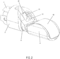
- Figures 1 and 2 both show a perspective view of a first embodiment of an endoscope head 1 according to the invention. More precisely, Fig. 1 shows a disassembled state of the endoscope head 1 and Fig. 2 shows the assembled state.
- the endoscope head 1 shown in the Figures forms part of an endoscope according to the invention.
- This endoscope may be formed as a flexible endoscope for the gastro-intestinal tract.
- the endoscope comprises an operation unit and an insertion portion.
- the operation unit is positioned on the proximal side and the insertion portion is positioned on the distal side of the endoscope.
- the operation unit (not shown in the drawings) comprises an actuating lever (such as a joystick or a simple lever arm, for example) for actuating an Albarran lever, a working channel inlet and an adjusting knob for bending a bending portion of the endoscope.
- the operation unit is connected to a video processor, a light source device, a display device and the like.
- the insertion portion is a long tube-like element.
- the proximal end of the insertion portion is connected with the operation unit.
- the insertion portion comprises, in this order seen from the operation unit, a flexible portion, the bending portion and a cap.
- the flexible portion is elastic.
- the bending portion is bent as a reaction to an actuation of the adjusting knob.
- a rigid end piece portion is formed on the distal end of the bending portion.
- the rigid end piece portion forms the so-called endoscope head.
- the inventive endoscope head 1 of Figures 1 and 2 comprises a longitudinal endoscope head body 11 and a subsequently further described housing sheath part 3 including a subsequently further described Albarran lever 20.
- the endoscope head body 11 is constructed in a cylinder-like manner and, on the distal side thereof, provided with an ultrasonic head chamber 4 in which an ultrasonic head 40 is installed. On its proximal side, the endoscope head body 11 is connected to an operation unit (not shown) via a cable (not shown) or without a cable. The operation unit is used to control the endoscope head 1.
- the endoscope head body 11 comprises a working channel 13 and a pulling wire channel 14 (see Figure 7 ), both extending along the longitudinal direction of the endoscope head body 11 and parallel to each other.
- the pulling wire channel 14 contains a subsequently described pulling wire for actuating the subsequently described Albarran lever 20.
- the working channel 13 guides micro tools for examining e.g. the esophagus or the duodenum, the bile duct, the gall bladder, the pancreatic duct, the pancreas, etc.
- the Albarran lever 20 which is described below and able to change the lateral alignment of the micro tools in the known manner is arranged at the outlet of the working channel 13.
- the Albarran lever 20 changes the alignment angle of the micro tools advanced through the working channel 13 in parallel to the axis of the endoscope head 1.
- the alignment of the micro tools is then changed to a lateral direction by means of the Albarran lever 20, the micro tools then project laterally from the endoscope head so as to be advanced in a bile duct, for example.
- the shape and the deflection angle of the Albarran lever are not restricted in the present invention.
- the endoscope head body 11 comprises an Albarran lever chamber 12 extending in the embodiment from a region near the longitudinal axis of the endoscope head body 11 in the radial direction.
- the Albarran lever chamber 12 is open in the radial direction.
- the Albarran lever chamber 12 extends in the axial direction of the endoscope head body 11.
- the working channel 13 enters into the Albarran lever chamber 12.
- the ultrasonic head chamber 4 is provided.
- the endoscope head body 11 comprises two lateral extension portions 11A and 11B which are formed as side walls or side portions and are adjacent to the Albarran lever chamber 12. More precisely, as is shown in Figures 1 , 2 and 6 to 8, the endoscope head body 11 includes a first side portion 11A for a camera and an illumination means, and a second side portion 11B for a pulling wire.
- the direction in which the camera 17 and the illumination means 18 are aligned is defined as the viewing direction.
- the illumination means 18 is positioned on the distal end of the first side portion 11A and the camera 17 is provided proximally to the illumination means 18.
- the supply lines and signal lines for the camera 17 and the illumination means 18 can be arranged inside the first side portion 11A. These supply lines and signal lines extend toward the operation unit.
- a pulling wire channel 14 as a movement transmission channel, a pulling wire end and a pivot lever 6 are accommodated in the second side portion 11B.
- the first side portion 11A and the second side portion 11B are formed in a flat manner such that a flattening 19 of the endoscope head body 11 is provided.
- the flattening 19 of the endoscope head body 11 is a plane surface facing toward the viewing direction.
- the camera 17 and the illumination means 18 are arranged distally to the flattening 19.
- the Albarran lever chamber 12 is sandwiched between and laterally delimited by the first side portion 11A and the second side portion 11B.
- the limitation walls of the first side portion 11A and the second side portion 11B extend in an approximately radial direction in parallel to each other.
- the Albarran lever chamber 12 in the embodiment has a cuboid shape.
- the limitation walls of the first side portion 11A and the second side portion 11B are perpendicular to the flattening 19.
- An accommodation chamber 11B1 is formed in the second side portion 11B.
- the accommodation chamber 11B1 On the distal side, on the proximal side, on the side facing towards the Albarran lever chamber 12, on the side facing towards the viewing direction and on the side opposed to the viewing direction, the accommodation chamber 11B1 is surrounded by the second side portion 11B and is open only on the side opposed to the Albarran lever chamber 12.
- the pulling wire (control wire) extends up to the operation unit and is actuated by the actuating lever for actuating an Albarran lever.
- a pivot lever 6 is rotatably supported in the accommodation chamber 11B1. More precisely, a bearing bore (passage bore) 11B2 extends through the wall of the accommodation chamber 11B1, which is provided on the side facing towards the Albarran lever chamber 12. This bearing bore 11B2 connects the accommodation chamber 11B1 with the Albarran lever chamber 12.
- the pivot lever rotating shaft 62 of the pivot lever 6 is rotatably supported in the bearing bore 11B2.
- the pivot lever rotating shaft 62 protrudes on both sides of the bearing bore 11B2, i.e. on the side of the accommodation chamber 11B1 and on the side of the Albarran lever chamber 12.
- the pivot lever rotating shaft 62 is installed in a sealed manner in the bearing bore 11B2.
- the pivot lever rotating shaft 62 is formed perpendicularly to the pivot lever 6 and integrally with the pivot lever 6 on an end portion of the pivot lever 6.
- the pivot lever rotating shaft 62 and the pivot lever 6 may be formed as one body or may be separate components which are connected with each other in a form-fitting or force-fitting manner.
- the pivot lever 6 has a pulling wire nipple accommodation 63 on the end portion opposed to the pivot lever rotating shaft 62.
- the pulling wire nipple accommodation 63 may be molded to the pivot lever 6 or fixed to the pivot lever 6 as a separate body.
- the distal pulling wire end of the pulling wire is hooked in or fitted in the pulling wire nipple accommodation 63 or otherwise fixed thereto.
- the cover member 5 is a flat plate member adapted to the outer contour of the endoscope head body 11 and has a suitable size completely covering the open side of the accommodation chamber 11B1.
- the cover member 5 covers the open side of the accommodation chamber 11B1 in such a manner that the open side of the accommodation chamber 11B1 is (watertightly) sealed.
- the cover member 5 is screwed to the outer circumference of the endoscope head body 11 by means of two screws so as to cover the accommodation chamber 11B1, as it is shown in Fig. 1 .
- the accommodation chamber 11B1 except for the pulling wire channel, is completely sealed. In other words, the pulling wire channel is completely sealed against the environment (in a watertight manner).
- the pin 16 formed as a round rod body is arranged as an operating element.
- the pin 16 extends from the pivot lever rotating shaft 62 approximately in parallel to the pivot lever 6.
- the pin 16 may also extend from the pivot lever rotating shaft 62 at a predetermined angle offset with respect to the pivot lever 6 in the proximal or the distal direction.
- the relative extension direction of the pin 16 and the pivot lever 6 is not restricted in the invention and can be appropriately selected.
- the pin 16 can be actuated by means of the actuating lever of the operation unit by pulling the pulling wire via the actuating lever; this causes the pulling wire nipple accommodation 63 to be pivoted about the pivot lever rotating shaft 62 as rotation point and the pin 16 to be rotated about the same angular extent.
- An ultrasonic head chamber 4 is arranged on the distal side of the endoscope head body 11.
- the ultrasonic head chamber 4 may be constructed in any suitable manner and holds the ultrasonic head 40 therein such that the ultrasonic head 40 is at least aligned to the viewing direction.
- the ultrasonic head 40 is capable of transmitting and receiving ultrasonic signals in the viewing direction.
- the ultrasonic head 40 is configured such that it is capable of transmitting and receiving ultrasonic signals in and from directions which are not limited to the viewing direction alone.
- the ultrasonic head chamber 4 may be mounted on the distal side of the endoscope head body 11 or form an integral unit with the endoscope head body 11. Alternatively, the ultrasonic head chamber 4 may be dismounted on the distal side of the endoscope head body 11.
- grooves 15 extending in the axial direction of the endoscope head body 11 are provided on the endoscope head body 11. More precisely, a first groove 15 is formed on the first side portion 11A below the accommodation chamber 11B1 (i.e. on the side opposed to the flattening 19) on the outer circumferential surface of the endoscope head body 11.
- a second groove 15 is provided on the second side portion 11B on the same level as the first groove 15 and parallel to the first groove 15.
- the second groove 15 is not visible in the drawings since it is positioned on the side of the endoscope head body 11, which faces away from the viewer.
- the first groove 15 and the second groove 15 are formed as longitudinal recesses or depressions.
- the housing sheath part 3 comprises a sheath 31 having a hollow cylinder-like shape.
- the inner contour of the sheath 31 of the housing sheath part 3 is adapted to the outer contour of the endoscope head body 11. More precisely, the hollow cylinder shape of the sheath 31 is open on one cylinder sheath side.
- the sheath 31 includes two lateral extensions which are elastic.
- the cylinder sheath side of the sheath 31 is open between the ends of the lateral extensions.
- the sheath 31 is elastic and can be bent open on the lateral extensions thereof.
- an attachment opening 32 is provided between the ends of the lateral extensions. Since the housing sheath part 3 is elastic, the attachment opening 32 can be expanded by bending open the sheath ends adjacent to the attachment opening 32.
- the housing sheath part 3 can be placed on the endoscope head body 11 by inserting the endoscope head body 11 quasi through the attachment opening 32 into the sheath 31, see Figures 1 and 2 .
- the housing sheath part 3 On the circumferential side opposed to the attachment opening 32, the housing sheath part 3 has a tool opening 33 extending in the axial direction of the housing sheath part 3.
- the tool opening 33 When the housing sheath part 3 is placed on the endoscope head body 11, the tool opening 33 is arranged exactly above the Albarran lever chamber 12.
- the size (in particular the width) of the tool opening 33 is adapted to the Albarran lever chamber 12.
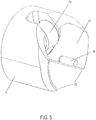
- ribs 35 are formed adjacent to the attachment opening 32, as this is shown in Figures 3 to 5 .
- Each rib 35 extends in the axial direction of the housing sheath part 3.
- the ribs 35 engage in the grooves 15.
- the shape and size of the ribs 35 is suitably adapted to the shape and size of the grooves 15.
- the housing sheath part 3 On the inner circumferential side, adjacent to the tool opening 33, the housing sheath part 3 has a housing sheath flattening adapted to the flattening 19. In this region adjacent to the tool opening 33, the housing sheath flattening is provided with a thicker wall thickness than the rest of the sheath 31. When the housing sheath part 3 is placed on the endoscope head body 11, the housing sheath flattening abuts against the flattening 19.
- a protrusion 34 is formed on the housing sheath flattening. The protrusion 34 extends radially inwards in the housing sheath part 3, perpendicular to the housing sheath flattening. The protrusion 34 forms an Albarran lever holder. The protrusion 34 is formed to be flat and projects into the Albarran lever chamber 12 when the housing sheath part 3 is arranged on the endoscope head body 11.
- the protrusion 34 On the end portion opposed to the housing sheath flattening, the protrusion 34 has a passage bore 341 formed perpendicular to the extension direction of the protrusion 34 and perpendicular to the axis of the housing sheath part 3.
- An Albarran lever shaft 21 is rotatably supported in the passage bore 341.
- the Albarran lever shaft 21 protrudes laterally from the Albarran lever 20, as it is shown in Figure 3 .
- the Albarran lever 20 is rotatably supported on the radially inner end portion of the protrusion 34.
- the Albarran lever 20 has an insertion bore which is not shown in the drawings and in which the previously described pin 16 is inserted.
- the inner diameter of the insertion bore of the Albarran lever 20 is adapted to the outer diameter of the pin 16, such that a smooth relative displacement between the pin 16 and the insertion bore of the Albarran lever 20 is realized.
- the Albarran lever 20 When the housing sheath part 3 is placed on the endoscope head body 11, the Albarran lever 20 is slid on the pin 16. In other words, in this position the pin 16 engages in the Albarran lever 20 and can pivot the Albarran lever.
- the Albarran lever 20 can be applied (inserted) on the endoscope head body 11 laterally to the axis of the endoscope head body 11 and, in turn, removed from the endoscope head body 11 laterally to the axis of the endoscope head body 11.
- the Albarran lever shaft 21 is arranged at a position which forms an imagined extension to the pivot lever rotating shaft 62.
- the Albarran lever 20 may have any suitable shape and includes a tool pushing surface 22.
- tools guided through the working channel 13 can be pushed to the lateral side of the endoscope head body 11 in the known manner.
- the tool pushing surface 22 is positioned opposite to the orifice of the working channel 13 into the Albarran lever chamber 12.
- the Albarran lever 20 can be slid on the pin 16 such that it extends approximately parallel to the pivot lever 6, as it is shown in Figures 6 and 7 .
- Fig. 6 shows the Albarran lever 20 in a non-pivoted state with the pulling wire being released.
- Fig. 7 shows the Albarran lever 20 in a pivoted state with the pulling wire being pulled.
- the housing sheath part 3 and the Albarran lever 20 form a common assembly.
- the housing sheath part 3 and the Albarran lever 20 are each made of plastic or any other cost-efficient material. They can be cost-efficiently manufactured by means of injection molding or a 3D-printer.
- the assembly consisting of the housing sheath part 3 and the Albarran lever 20 is suitable for single use. After the use, the assembly consisting of the housing sheath part 3 and the Albarran lever 20 can be disposed of.
- the endoscope itself comprising the endoscope head body 11 according to the invention includes hardly any undercuts and is therefore easy to clean.
- the Albarran lever 20, on the other hand includes undercuts and is more difficult to clean.
- the Albarran lever is completely separated from the pulling wire. Due to this construction, the pulling wire channel is sealed, with the pulling wire being completely sealed against the environment. The sealing of the pulling wire channel and the pulling wire is watertight.
- the housing sheath part as an Albarran lever holding member and the Albarran lever are made of plastic by means of a 3D-printer or injection molding, for example.
- the housing sheath part and the Albarran lever can be manufactured accurately, but still at low cost.
- Other appropriate manufacturing methods may be applied as long as they allow for an accurate and cost-efficient production.
- the housing sheath part and the Albarran lever are manufactured separately and then put together as an assembly for the purpose of a single use. In a molding step, the housing sheath part as sheath element and the Albarran lever are separately manufactured and in an assembly step, the Albarran lever is installed in the housing sheath part.
- the housing sheath part 3 is engaged at the endoscope head body 11 by the ribs 35 engaging in the grooves 15.
- the ribs 35 and the grooves 15 represent the fastening means by which the housing sheath part 3 is attached to the endoscope head body 11.
- the endoscope head 1 of the first embodiment and a housing sheath part 3 modified compared to the housing sheath part 3 of the first embodiment are applied. Therefore, only those aspects in which the second embodiment differs from the first embodiment are described in the following.
- another (additional) fastening means in the shape of a hinge member 310 is provided on the housing sheath part 3.
- the hinge member 310 bridges over the attachment opening 32.
- One side of the hinge member 310 is supported in a hinged manner on the housing sheath part 3 in an edge region of the attachment opening 32.
- the opposite side of the hinge member 310 includes a closing means, such as a nose 311, capable of engaging in an engagement groove 315 on the opposite edge region of the attachment opening 32 at the housing sheath part 3.
- the hinge mechanism of the hinge member 310 on the housing sheath part 3 may be formed as a film hinge. More precisely, the hinge member 310 is integrally provided on the housing sheath part 3 as a thin-walled connection (e.g. in the shape of a fold). Due to its flexibility, the thin-walled connection enables a rotational movement of the hinge member 310 on the housing sheath part 3. Manufacturing the film hinge is extremely cost-effective.
- the housing sheath part 3 corresponds to the housing sheath part 3 of the first embodiment.
- Fig. 14 shows a perspective view of an inventive housing sheath part of a third embodiment.
- the endoscope head 1 of the first embodiment and a housing sheath part 3 modified compared to the housing sheath part 3 of the first embodiment are applied.
- a housing sheath part 3 also includes the region of the housing sheath flattening, which is adjacent to the tool opening 33, as it is shown in Fig. 14 .
- the housing sheath part 3 does not include the two lateral extensions of the first embodiment which comprise the ribs 35 and the ends of which define the attachment opening 32.
- the housing sheath part 3 in the third embodiment includes only that portion of the housing sheath flattening which is adjacent to the tool opening 33.
- the housing sheath part 3 is provided with a fastening means in the shape of a hinge member 320.
- One side of the hinge member 320 is, on an edge region of the portion of the housing sheath flattening, supported on the housing sheath part 3 via a hinge mechanism 322.
- the opposite side of the hinge member 320 includes a closing means such as a nose 321 which can engage at the endoscope head body in an engagement groove provided for this purpose.
- the hinge mechanism of the two hinge members 320 on the housing sheath part 3 may be designed as a film hinge 322. More precisely, each of the hinge members 320 is integrally provided on the housing sheath part 3 in the shape of a thin-walled connection as a film hinge 322 (e.g. as a fold). Due to its flexibility, the thin-walled connection of the film hinge 322 enables a rotational movement of the hinge member 320 on the housing sheath part 3. The manufacture of the film hinge 322 is extremely cost-effective.
- the rib 35 is provided as a fastening means which is formed at the housing sheath part 3 and engages with the groove 15 of the endoscope head body 11. Adjacent to the attachment opening 32, a right and a left rib 35 is provided, each being parallel to the extension direction of the endoscope head body 11.
- the invention is not restricted thereto.
- one or more pin-like protrusions may be formed on the housing sheath part 3, which respectively engage in one or more hole-like recesses on the endoscope head body 11 instead of the groove 15. Any type of fastening means is possible, as long as the same ensures that the housing sheath part 3 is securely held in place at the endoscope head body 11.
- the rib 35 may also be formed on the endoscope head body 11 and the groove 15 acting together with the rib 35 may be formed on the housing sheath part 3. Further, screws by which the housing sheath part is screwed to the endoscope head body may be used as fastening means.
- Fastening means thus refers to any releasable fastening means.
- the region of the housing sheath flattening on the housing sheath part 3 is formed such that the wall thickness of the housing sheath part 3 is reinforced (see the drawings). Thereby, the housing sheath part 3 becomes more rigid and more stable.
- the invention is not restricted thereto.
- the wall thickness of the housing sheath part 3 may also be uniform.
- a protrusion 34 is shown as Albarran lever holder.
- the protrusion 34 extends approximately radially inward in the housing sheath part 3, in a manner perpendicular to the housing sheath flattening. In other words, the protrusion 34 projects downward from the housing sheath part 3.
- the protrusion 34 projects from the housing sheath part 3 downward into the Albarran lever chamber 12 on the right-hand side of the Albarran lever chamber 12, seen from the distal side.
- two flat protrusions 34 may protrude downward from the housing sheath part 3 into the Albarran lever chamber 12 on the right-hand and left-hand side of the Albarran lever chamber 12, seen from the distal side.
- each of these two protrusions 34 has a passage bore 341 in each of which a shaft end of the Albarran lever shaft 21 is rotatably supported. Then, the Albarran lever is supported in the housing sheath part 3 in a more stable manner.
- the cover member 5 is screwed to the outer circumference of the endoscope head body 11 by means of two screws, so as to cover the accommodation chamber 11B1.
- the cover member 5 may be glued to the outer circumference of the endoscope head body 11, so as to cover the accommodation chamber 11B1.
- the cover member 5 may be releasably attached to the outer circumference of the endoscope head body 11 by locking-engagement, so as to cover the accommodation chamber 11B1.
- the ribs 35 and the grooves 15 may be omitted.
- the housing sheath part 3 can then be kept closed by the hinge member 310 only and tightly abuts against the endoscope head body 11.
- the housing sheath part 3 is aligned towards the endoscope head body 11 via the connection between the Albarran lever 20 and the pin 16. In this way, the relative position between the housing sheath part 3 and the endoscope head body 11 is sufficiently specified.
- the ends of the sheath 31 which are opposed to the flattening 19 and form the edge regions of the attachment opening 32 are formed to be thin on the housing sheath part 3, as it is shown in Fig. 4 , for example.
- the ends of the sheath 31 which are opposed to the flattening 19 have a thicker wall thickness and are provided with round U-depressions extending in parallel to the axial direction of the housing sheath part 3.
- the U-depressions are open towards the attachment opening 32.
- Round rod elements of an appropriate size can be inserted into the U-depressions.
- the round rod elements constitute the respective side edges of a plate member (not shown) inserted into the above-mentioned U-depressions from the distal or the proximal side.
- the round rod elements are formed in one piece with the plate member.
- the U-depressions have a smaller opening dimension on the open side so as to safely hold the round rods.
- the round rod elements can be snap-fitted into the U-depressions and are rotatably supported in the U-depressions.
- the plate member bridges over and closes the attachment opening 32.
- one of the two round rod elements of the plate member is fixedly seated in its U-depression of the housing sheath part, is rotatably supported thereon and cannot be pulled out.
- the other one of the two round rod elements is snap-fitted in its U-depression.
- the plate member functions in much the same way as the hinge member 310 of the second embodiment.
- one of the two round rod elements of the plate member is used as pivot bearing of the plate member on the housing sheath part 3 and the other one of the two round rod elements of the plate member is used as a closing member of the plate member on the housing sheath part 3.
- Fastening means fastening the housing sheath part 3 to the endoscope head body 11 are described in the embodiments.
- the rib 35, the groove 15 and the hinge member 310, 320 are specifically mentioned as examples.
- the invention is not restricted thereto.
- the term "fastening means" shall include any fastening means suitable to fasten the housing sheath part 3 to the endoscope head body 11.
- the fastening means may be attached to the housing sheath part 3 or to the endoscope head body 11 or to both of them.
- the ultrasonic head is arranged on the distal end of the endoscope head, and the endoscope head includes an Albarran lever arranged proximally from the ultrasonic head.
- the invention may also be applied to an endoscope head including an Albarran lever arranged distally from the ultrasonic head.
- a working channel and a movement transmission channel are guided past the ultrasonic head. This can be easily accomplished by arranging, with reference to Fig. 1 , an ultrasonic head chamber similar to the ultrasonic head chamber 4 between the proximal portion of the endoscope 1 and the endoscope head body 11. The endoscope head body 11 is then arranged on the distal end of the endoscope.
- the ultrasonic head chamber 4 is arranged proximally of the endoscope head body 11, the bottom region of the ultrasonic head chamber 4 including a working channel portion and a movement transmission channel portion, extending below the ultrasonic head 40 in the bottom region of the ultrasonic head chamber 4 towards the endoscope head body 11.
- the present invention may preferably be applied to a duodenoscope, a gastroscope, a colonoscope or a similar endoscope.
- the principle of the invention may as well be applied to any other type of endoscope.
Landscapes
- Health & Medical Sciences (AREA)
- Life Sciences & Earth Sciences (AREA)
- Surgery (AREA)
- General Health & Medical Sciences (AREA)
- Medical Informatics (AREA)
- Veterinary Medicine (AREA)
- Pathology (AREA)
- Radiology & Medical Imaging (AREA)
- Biophysics (AREA)
- Engineering & Computer Science (AREA)
- Biomedical Technology (AREA)
- Heart & Thoracic Surgery (AREA)
- Nuclear Medicine, Radiotherapy & Molecular Imaging (AREA)
- Molecular Biology (AREA)
- Animal Behavior & Ethology (AREA)
- Physics & Mathematics (AREA)
- Public Health (AREA)
- Optics & Photonics (AREA)
- Gastroenterology & Hepatology (AREA)
- Endoscopes (AREA)
- Ultra Sonic Daignosis Equipment (AREA)
- Instruments For Viewing The Inside Of Hollow Bodies (AREA)
Description
- The present invention relates to an endoscope head comprising an endoscope head body, in which at least one working channel is formed and in which an Albarran lever capable of being pivoted is provided at the distal working channel end portion, and to an endoscope comprising such an endoscope head. Further, the present invention relates to an Albarran lever holding member for an endoscope.
- Such an endoscope head body can, for example, be applied to a duodenoscope, i.e. an endoscope for examining e.g. the esophagus or the duodenum, the bile duct, the gall bladder, the pancreatic duct, the pancreas, etc.
- By means of the duodenoscope it is possible to reach the duodenum through the esophagus, the stomach and the pylorus.
- The duodenoscope comprises optics (illumination means and camera) directed to the side (lateral). This may complicate inserting and advancing the duodenoscope through the esophagus since a "forward-facing" observation is not easily possible. Only the stomach or the duodenum provides enough room to bend the distal end of the duodenoscope by about 90° so as to enable forward viewing.
- Further, at the working channel outlet, the duodenoscope comprises an Albarran lever which, by means of pivoting, enables a precise deflection of the tools advanced through the working channel.
- After the duodenoscope has been used, it is subjected to reprocessing. The reprocessing must reliably prevent microorganisms such as bacteria, viruses, fungi, worms and spores from being transmitted. In the course of reprocessing, the duodenoscope is initially cleaned manually in order to remove all traces of organic material or chemical residues. After cleaning, a mechanical disinfection or sterilization is carried out.
-
US 4 436 087 A discloses an Albarran lever holding member for an endoscope comprising an endoscope head including the features of the preamble ofclaim 1. In this document, a ring shaped cylindrical hood is fitted from the distal side to the endoscope end portion. -
US 2005/234297 A1 discloses an endoscope having an end portion on which indeed a base is laterally attached. The base acts as a housing sheath part and is formed like a longitudinally cut half cylinder. At its outer surface a pivotable articulation main body is arranged. The articulation main body actually forms an effective end of a channel. Due to its pivoting the articulation main body can bend an instrument guided through the channel. -
JP 3 159464 B2 - It is the object of the present invention to provide an endoscope head comprising an endoscope head body, which is easy to clean but also versatile. Moreover, an endoscope and an Albarran lever holding member for an endoscope shall be provided.
- This object is achieved by an Albarran lever holding member for an endoscope comprising an endoscope head including the features of
claim 1. An endoscope head having such an Albarran lever holding member is stated inclaim 3. An endoscope comprising such an endoscope head is stated inclaim 17. Advantageous further developments are described in the dependent claims. - Thus, an endoscope head has been provided which comprises an endoscope head body, in which at least one working channel is formed, wherein an Albarran lever capable of being pivoted is provided at the distal working channel end portion. The Albarran lever can be inserted at the endoscope head body laterally to the axis of the endoscope head body and removed from the endoscope head body laterally to the axis of the endoscope head body. Thus, the Albarran lever can be removed from the endoscope head body laterally to the axis of the endoscope head body and is easily detachable from the endoscope head body.
- The endoscope head may comprise a housing sheath part at which the Albarran lever is pivotally disposed, wherein the housing sheath part can be applied at and removed from an outer circumferential portion of the endoscope head body laterally to the axis of the endoscope head body. The housing sheath part and the Albarran lever may form a common assembly which is separate from the endoscope head and can be treated as an individual unit. Hence, the Albarran lever provided on the housing sheath part is provided separately and detachably from the endoscope head body. The Albarran lever can be separated from the endoscope head body by the housing sheath part being removed from the endoscope head body.
- In the endoscope head, the housing sheath part may be formed as an elastic housing sheath part which can be spread apart and can be completely separated from the endoscope head body, and which can include fastening means which fasten the housing sheath part to the outer circumferential portion of the endoscope head body. Thus, the assembly consisting of the housing sheath part and the Albarran lever can be easily attached to the endoscope head. The fastening means can be formed as engagement means. Protrusions capable of engaging in recesses formed on the outer circumferential portion of the endoscope head body may be formed as engagement means on the housing sheath part.
- The housing sheath part may be formed as a hollow cylinder whose sheath includes an attachment opening extending along the cylinder extension direction and along the entire hollow cylinder. The hollow cylinder may be elastically spread apart at the attachment opening thereof and placed on the outer circumferential portion of the endoscope head body. Thus, the housing sheath part can be easily and quickly detached from the endoscope head body.
- On the hollow cylinder, on the side opposite to the attachment opening, a tool opening may be formed, through which a tool can project laterally from the endoscope head body when the housing sheath part is placed on the endoscope head body. When the housing sheath part is attached to the endoscope head body, the endoscope is ready for operation. Tools can be advanced through the working channel to the Albarran lever which appropriately changes the lateral alignment of the tools. In the course of this, the tools project laterally from the endoscope head body through the tool opening of the housing sheath part.
- The fastening means may be formed as a hinge member. The housing sheath part may comprise a hinge member which is hinged on the housing sheath part and is able to close the attachment opening. When the hinge member is closed, the housing sheath part can abut against the endoscope head body along the entire outer circumferential portion of the endoscope head body. In such a design, the housing sheath part is mounted to the endoscope head body in a fixed and stable manner. One side of the hinge member may be supported on the housing sheath part in a hinged manner and the opposite side of the hinge member may include a closing means, e.g. a nose, capable of engaging at the housing sheath part. Due to the elasticity of the housing sheath part, the housing sheath part can thus tightly abut against the endoscope head body in a correct position and with a predefined tension.
- The housing sheath part may comprise a protrusion extending radially inward, on which the pivot axis of the Albarran lever is rotatably supported. Therefore, the housing sheath part is provided with the elements pivotally supporting the Albarran lever. The element (operating element) effecting the pivoting process of the Albarran lever may be provided in the endoscope head body.
- The housing sheath part and the Albarran lever may be formed as a unit designed as a single-use product. For example, the housing sheath part and the Albarran lever can form a common assembly which is manufactured at low cost from plastic or any other suitable material. Thus, the common assembly consisting of the housing sheath part and the Albarran lever can be disposed of after a single use. When the endoscope is used again, a new assembly consisting of the housing sheath part and the Albarran lever is placed on the endoscope head body.
- The endoscope head body may comprise a pivotable operating element which can be operated from the proximal side and with which the Albarran lever releasably engages when the housing sheath part is attached to the endoscope head body.
- The endoscope head may comprise an ultrasonic head on the distal end of the endoscope head body and the portion of the endoscope head body where the Albarran lever can be applied at and removed from, may be situated proximally from the ultrasonic head. In this way, an endoscope can be provided which comprises an ultrasonic head on the distal end and includes, proximally from the ultrasonic head, an Albarran lever which is easily separable from the endoscope head.
- In an alternative, an endoscope head according to the invention has been provided, the endoscope head comprising an ultrasonic head at the distal end and an Albarran lever arranged proximally from the ultrasonic head.
- In a further alternative, an endoscope head according to the invention has been provided, the endoscope head comprising an ultrasonic head therein and an Albarran lever arranged distally from the ultrasonic head. In this further alternative, a working channel and a movement transmission channel are guided past the ultrasonic head.
- In the endoscope head, the Albarran lever may be operated by means of a movement transmission mechanism, wherein the movement transmission mechanism in the endoscope head acts via a movement transmission channel and the movement transmission channel is sealed against the environment.
- The movement transmission mechanism may be, for example, a pulling wire mechanism, a wire mechanism (pushing wire or pulling wire), a hydraulic mechanism or a pneumatic mechanism, transmitting a movement generated at a proximal control element (e.g. a joystick) via the movement transmission channel so as to actuate (pivot) the Albarran lever. In the case of the solution by means of the hydraulic mechanism or the pneumatic mechanism, the movement transmission channel is a simple channel which is sealed and filled with a movement transmission medium (hydraulic mechanism: e.g. water or another hydraulic medium; pneumatic mechanism: e.g. air).
- Since the movement transmission channel and thus, the medium contained therein (hydraulic medium, air, pulling wire or wire, etc.) is sealed against the environment, it is avoided that germs and contaminations enter the movement transmission channel. Incidentally, the movement transmission channel and the Albarran lever are completely separated from each other.
- Moreover, an Albarran lever holding member has been provided for an endoscope comprising an endoscope head in which at least one working channel is formed, wherein an Albarran lever capable of being pivoted is provided at the distal working channel end portion of the endoscope; the Albarran lever holding member including: a sheath element which can be placed on the endoscope head and in which the Albarran lever is pivotally supported.
- The sheath element may be formed as a laterally open cylinder whose open side can be placed on the endoscope head, and the Albarran lever pivotally supported in the sheath element may include an opening adapted to be able to engage such that an operating element supported on the endoscope head can engage in the opening of the Albarran lever.
- The Albarran lever holding member may be formed of plastic, for example, or any other suitable material. The Albarran lever holding member may be manufactured, for example, by means of a 3D-printer or an injection molding method. The sheath element and the Albarran lever can be manufactured separately and the Albarran lever can be installed in the sheath element in an assembly step.
- The previously explained aspects of the present invention may be appropriately combined.
-
-
Fig. 1 shows a perspective view of an inventive endoscope head of a first embodiment in a disassembled state. -
Fig. 2 shows a perspective view of the inventive endoscope head of the first embodiment in the assembled state. -
Fig. 3 shows a perspective view of a housing sheath part of the inventive endoscope head of the first embodiment. -
Fig. 4 shows a further perspective view of a housing sheath part of the inventive endoscope head of the first embodiment. -
Fig. 5 shows a further perspective view of a housing sheath part of the inventive endoscope head of the first embodiment. -
Fig. 6 shows a perspective view of an endoscope head body of the endoscope head of the first embodiment with an Albarran lever being in a non-pivoted state. -
Fig. 7 shows a perspective view of the endoscope head body of the endoscope head of the first embodiment with the Albarran lever being in a pivoted state. -
Fig. 8 shows a perspective view of the endoscope head of the first embodiment obliquely from above, without the housing sheath part. -
Fig. 9 shows a perspective view of an inventive endoscope head of a second embodiment in a disassembled state. -
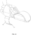
Fig. 10 shows a perspective view of the inventive endoscope head of the second embodiment, with a housing sheath part being placed on the endoscope head. -
Fig. 11 shows a perspective view of the inventive endoscope head of the second embodiment, with a hinge member of the housing sheath part being closed. -
Fig. 12 shows a perspective view of the inventive endoscope head of the second embodiment with the hinge member of the housing sheath part on the endoscope head being closed. -
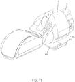
Fig. 13 shows a perspective view of the inventive endoscope head of the second embodiment, with a hinge member of the housing sheath part being closed. -
Fig. 14 shows a perspective view of an inventive housing sheath part of a third embodiment. - Below, the present invention is described in detail with reference to the drawings and based on the embodiments.
- The endoscope head of the present invention can be used in the field of endoscopic ultrasound.
- Endoscopic ultrasound (EUS) is a medical procedure in which endoscopy is combined with ultrasound to obtain images of the internal organs e.g. in the chest, abdomen and colon. EUS can be used to visualize the walls of these organs, or to look at adjacent structures. Combined with Doppler imaging, nearby blood vessels can also be evaluated.
- Endoscopic ultrasonography is most commonly used in the upper digestive tract and in the respiratory system. For the patient, the procedure feels almost identical to the endoscopic procedure without the ultrasound part, unless ultrasound-guided biopsy of deeper structures is performed.
- Ultrasound endoscopes are commonly used for diagnostic and therapeutic purposes in the upper gastroenterology area. The tools in use are penetrating the human tissue and are out of optical visibility, in that moment. In that case the ultrasound sensor still shows the way and location of the tools tip. Necessary tools can be controlled by the albarranlever of the respective endoscope. The physician observes e.g. either the stomach or the duodenum with the optical camera as well as taking pancreatic biopsy with support from the EUS sensors view.
- In particular, for endoscopic ultrasound of the upper digestive tract, a probe is inserted into the esophagus, stomach, and duodenum during a esophagogastroduodenoscopy. Among other uses, it allows for screening for pancreatic cancer, esophageal cancer, and gastric cancer, as well as benign tumors of the upper gastrointestinal tract. It also allows for characterization and biopsy of any focal lesions found in the upper gastrointestinal tract, such as esophageal tuberculosis. Further, this procedure can also be used to identify malformations and masses in the bile ducts and pancreatic ducts.
- Endoscopic ultrasound is performed with the patient sedated. The ultrasound endoscope is passed through the mouth and advanced through the esophagus to the suspicious area. From various positions between the esophagus and duodenum, organs within and outside the gastrointestinal tract can be imaged to see if they are abnormal, and they can be biopsied by a process called fine needle aspiration. Organs such as the liver, pancreas, and adrenal glands are easily biopsied, as are any abnormal lymph nodes. In addition, the gastrointestinal wall itself can be imaged to see if it is abnormally thick, suggesting inflammation or malignancy.
- The technique is highly sensitive for detection of pancreatic cancer. With respect to pancreatic cancer, by endoscopic ultrasound local metastases can be detected. However, in combination with a CT scan which provides information on regional metastases, endoscopic ultrasound provides an excellent imaging modality for diagnosis and staging of pancreatic carcinoma.
- Endoscopic ultrasound can also be used in conjunction with endoscopic retrograde cholangio pancreatography. The ultrasound probe is used to locate gall stones which may have migrated into the common bile duct.
- Endoscopic ultrasound can also be used for imaging of the rectum and colon, although these applications are lesser known. Endoscopic ultrasound can be used primarily to stage newly diagnosed rectal or anal cancer. EUS-guided fine needle aspiration may be used to sample lymph nodes during this procedure. Evaluation of the integrity of the anal sphincters may also be done during lower EUS procedures.
- An endoscopic ultrasound probe placed in the esophagus can also be used to visualize lymph nodes in the chest surrounding the airways (bronchi), which is important for the staging of lung cancer. Ultrasound can also be performed with an endoscopic probe inside the bronchi themselves, a technique known as endobronchial ultrasound.
- First of all, a first embodiment of the present invention is described with reference to
Figures 1 to 8 . -
Figures 1 and2 both show a perspective view of a first embodiment of anendoscope head 1 according to the invention. More precisely,Fig. 1 shows a disassembled state of theendoscope head 1 andFig. 2 shows the assembled state. - The
endoscope head 1 shown in the Figures forms part of an endoscope according to the invention. This endoscope may be formed as a flexible endoscope for the gastro-intestinal tract. The endoscope comprises an operation unit and an insertion portion. The operation unit is positioned on the proximal side and the insertion portion is positioned on the distal side of the endoscope. The operation unit (not shown in the drawings) comprises an actuating lever (such as a joystick or a simple lever arm, for example) for actuating an Albarran lever, a working channel inlet and an adjusting knob for bending a bending portion of the endoscope. The operation unit is connected to a video processor, a light source device, a display device and the like. - The insertion portion is a long tube-like element. The proximal end of the insertion portion is connected with the operation unit. The insertion portion comprises, in this order seen from the operation unit, a flexible portion, the bending portion and a cap. The flexible portion is elastic. The bending portion is bent as a reaction to an actuation of the adjusting knob. A rigid end piece portion is formed on the distal end of the bending portion. The rigid end piece portion forms the so-called endoscope head.
- The
inventive endoscope head 1 ofFigures 1 and2 comprises a longitudinalendoscope head body 11 and a subsequently further describedhousing sheath part 3 including a subsequently further describedAlbarran lever 20. - The
endoscope head body 11 is constructed in a cylinder-like manner and, on the distal side thereof, provided with anultrasonic head chamber 4 in which anultrasonic head 40 is installed. On its proximal side, theendoscope head body 11 is connected to an operation unit (not shown) via a cable (not shown) or without a cable. The operation unit is used to control theendoscope head 1. - The
endoscope head body 11 comprises a workingchannel 13 and a pulling wire channel 14 (seeFigure 7 ), both extending along the longitudinal direction of theendoscope head body 11 and parallel to each other. The pullingwire channel 14 contains a subsequently described pulling wire for actuating the subsequently describedAlbarran lever 20. The workingchannel 13 guides micro tools for examining e.g. the esophagus or the duodenum, the bile duct, the gall bladder, the pancreatic duct, the pancreas, etc. TheAlbarran lever 20 which is described below and able to change the lateral alignment of the micro tools in the known manner is arranged at the outlet of the workingchannel 13. In other words, theAlbarran lever 20 changes the alignment angle of the micro tools advanced through the workingchannel 13 in parallel to the axis of theendoscope head 1. The alignment of the micro tools is then changed to a lateral direction by means of theAlbarran lever 20, the micro tools then project laterally from the endoscope head so as to be advanced in a bile duct, for example. - The shape and the deflection angle of the Albarran lever are not restricted in the present invention.
- As shown in
Figures 1 ,2 and5 , theendoscope head body 11 comprises anAlbarran lever chamber 12 extending in the embodiment from a region near the longitudinal axis of theendoscope head body 11 in the radial direction. In other words, theAlbarran lever chamber 12 is open in the radial direction. Moreover, theAlbarran lever chamber 12 extends in the axial direction of theendoscope head body 11. On the proximal side of theAlbarran lever chamber 12, the workingchannel 13 enters into theAlbarran lever chamber 12. On the distal side of theAlbarran lever chamber 12, theultrasonic head chamber 4 is provided. - The
endoscope head body 11 comprises twolateral extension portions Albarran lever chamber 12. More precisely, as is shown inFigures 1 ,2 and6 to 8, theendoscope head body 11 includes afirst side portion 11A for a camera and an illumination means, and asecond side portion 11B for a pulling wire. - A
camera 17 and an illumination means 18, aligned laterally upwards inFigures 1 ,2 and6 to 8 , are installed in thefirst side portion 11A. The direction in which thecamera 17 and the illumination means 18 are aligned is defined as the viewing direction. In the embodiment, the illumination means 18 is positioned on the distal end of thefirst side portion 11A and thecamera 17 is provided proximally to the illumination means 18. Thus, the supply lines and signal lines for thecamera 17 and the illumination means 18 can be arranged inside thefirst side portion 11A. These supply lines and signal lines extend toward the operation unit. - As is described below in further detail, a pulling
wire channel 14 as a movement transmission channel, a pulling wire end and apivot lever 6 are accommodated in thesecond side portion 11B. - On the side directed to the viewing direction, the
first side portion 11A and thesecond side portion 11B are formed in a flat manner such that a flattening 19 of theendoscope head body 11 is provided. The flattening 19 of theendoscope head body 11 is a plane surface facing toward the viewing direction. In the embodiment, thecamera 17 and the illumination means 18 are arranged distally to the flattening 19. - Thus, the
Albarran lever chamber 12 is sandwiched between and laterally delimited by thefirst side portion 11A and thesecond side portion 11B. The limitation walls of thefirst side portion 11A and thesecond side portion 11B extend in an approximately radial direction in parallel to each other. Thus, theAlbarran lever chamber 12 in the embodiment has a cuboid shape. The limitation walls of thefirst side portion 11A and thesecond side portion 11B are perpendicular to the flattening 19. - An accommodation chamber 11B1 is formed in the
second side portion 11B. On the distal side, on the proximal side, on the side facing towards theAlbarran lever chamber 12, on the side facing towards the viewing direction and on the side opposed to the viewing direction, the accommodation chamber 11B1 is surrounded by thesecond side portion 11B and is open only on the side opposed to theAlbarran lever chamber 12. The pullingwire channel 14, in which a pulling wire (control wire, not shown) is guided, opens out on the proximal side of the accommodation chamber 11B1. The pulling wire (control wire) extends up to the operation unit and is actuated by the actuating lever for actuating an Albarran lever. - A
pivot lever 6 is rotatably supported in the accommodation chamber 11B1. More precisely, a bearing bore (passage bore) 11B2 extends through the wall of the accommodation chamber 11B1, which is provided on the side facing towards theAlbarran lever chamber 12. This bearing bore 11B2 connects the accommodation chamber 11B1 with theAlbarran lever chamber 12. The pivotlever rotating shaft 62 of thepivot lever 6 is rotatably supported in the bearing bore 11B2. The pivotlever rotating shaft 62 protrudes on both sides of the bearing bore 11B2, i.e. on the side of the accommodation chamber 11B1 and on the side of theAlbarran lever chamber 12. The pivotlever rotating shaft 62 is installed in a sealed manner in the bearing bore 11B2. Thus, the accommodation chamber is (watertightly) sealed against theAlbarran lever chamber 12. The pivotlever rotating shaft 62 is formed perpendicularly to thepivot lever 6 and integrally with thepivot lever 6 on an end portion of thepivot lever 6. The pivotlever rotating shaft 62 and thepivot lever 6 may be formed as one body or may be separate components which are connected with each other in a form-fitting or force-fitting manner. Thepivot lever 6 has a pullingwire nipple accommodation 63 on the end portion opposed to the pivotlever rotating shaft 62. The pullingwire nipple accommodation 63 may be molded to thepivot lever 6 or fixed to thepivot lever 6 as a separate body. The distal pulling wire end of the pulling wire is hooked in or fitted in the pullingwire nipple accommodation 63 or otherwise fixed thereto. - The open side of the accommodation chamber 11B1, i.e. the side of the accommodation chamber 11B1 opposed to the
Albarran lever chamber 12, is closed by acover member 5. Thecover member 5 is a flat plate member adapted to the outer contour of theendoscope head body 11 and has a suitable size completely covering the open side of the accommodation chamber 11B1. Thecover member 5 covers the open side of the accommodation chamber 11B1 in such a manner that the open side of the accommodation chamber 11B1 is (watertightly) sealed. For example, thecover member 5 is screwed to the outer circumference of theendoscope head body 11 by means of two screws so as to cover the accommodation chamber 11B1, as it is shown inFig. 1 . Thus, the accommodation chamber 11B1, except for the pulling wire channel, is completely sealed. In other words, the pulling wire channel is completely sealed against the environment (in a watertight manner). - On the end of the pivot
lever rotating shaft 62, arranged in theAlbarran lever chamber 12, thepin 16 formed as a round rod body is arranged as an operating element. Thepin 16 extends from the pivotlever rotating shaft 62 approximately in parallel to thepivot lever 6. However, thepin 16 may also extend from the pivotlever rotating shaft 62 at a predetermined angle offset with respect to thepivot lever 6 in the proximal or the distal direction. The relative extension direction of thepin 16 and thepivot lever 6 is not restricted in the invention and can be appropriately selected. - Thus, the
pin 16 can be actuated by means of the actuating lever of the operation unit by pulling the pulling wire via the actuating lever; this causes the pullingwire nipple accommodation 63 to be pivoted about the pivotlever rotating shaft 62 as rotation point and thepin 16 to be rotated about the same angular extent. - An Albarran lever described in the following can be placed on the
pin 16. - An
ultrasonic head chamber 4 is arranged on the distal side of theendoscope head body 11. Theultrasonic head chamber 4 may be constructed in any suitable manner and holds theultrasonic head 40 therein such that theultrasonic head 40 is at least aligned to the viewing direction. Theultrasonic head 40 is capable of transmitting and receiving ultrasonic signals in the viewing direction. Ideally, theultrasonic head 40 is configured such that it is capable of transmitting and receiving ultrasonic signals in and from directions which are not limited to the viewing direction alone. - The
ultrasonic head chamber 4 may be mounted on the distal side of theendoscope head body 11 or form an integral unit with theendoscope head body 11. Alternatively, theultrasonic head chamber 4 may be dismounted on the distal side of theendoscope head body 11. - As it is shown in
Figure 1 ,grooves 15 extending in the axial direction of theendoscope head body 11 are provided on theendoscope head body 11. More precisely, afirst groove 15 is formed on thefirst side portion 11A below the accommodation chamber 11B1 (i.e. on the side opposed to the flattening 19) on the outer circumferential surface of theendoscope head body 11. - A
second groove 15 is provided on thesecond side portion 11B on the same level as thefirst groove 15 and parallel to thefirst groove 15. Thesecond groove 15 is not visible in the drawings since it is positioned on the side of theendoscope head body 11, which faces away from the viewer. - The
first groove 15 and thesecond groove 15 are formed as longitudinal recesses or depressions. - The
housing sheath part 3 comprises asheath 31 having a hollow cylinder-like shape. The inner contour of thesheath 31 of thehousing sheath part 3 is adapted to the outer contour of theendoscope head body 11. More precisely, the hollow cylinder shape of thesheath 31 is open on one cylinder sheath side. Thus, thesheath 31 includes two lateral extensions which are elastic. The cylinder sheath side of thesheath 31 is open between the ends of the lateral extensions. Thesheath 31 is elastic and can be bent open on the lateral extensions thereof. Thus, anattachment opening 32 is provided between the ends of the lateral extensions. Since thehousing sheath part 3 is elastic, the attachment opening 32 can be expanded by bending open the sheath ends adjacent to theattachment opening 32. When the lateral extensions of thesheath 31 are bent open, thehousing sheath part 3 can be placed on theendoscope head body 11 by inserting theendoscope head body 11 quasi through the attachment opening 32 into thesheath 31, seeFigures 1 and2 . - On the circumferential side opposed to the attachment opening 32, the
housing sheath part 3 has atool opening 33 extending in the axial direction of thehousing sheath part 3. When thehousing sheath part 3 is placed on theendoscope head body 11, thetool opening 33 is arranged exactly above theAlbarran lever chamber 12. The size (in particular the width) of thetool opening 33 is adapted to theAlbarran lever chamber 12. - On the lateral extensions of the
sheath 31, on the end portion opposed to thetool opening 33,ribs 35 are formed adjacent to the attachment opening 32, as this is shown inFigures 3 to 5 . Eachrib 35 extends in the axial direction of thehousing sheath part 3. When thehousing sheath part 3 is placed on theendoscope head body 11, theribs 35 engage in thegrooves 15. The shape and size of theribs 35 is suitably adapted to the shape and size of thegrooves 15. - On the inner circumferential side, adjacent to the
tool opening 33, thehousing sheath part 3 has a housing sheath flattening adapted to the flattening 19. In this region adjacent to thetool opening 33, the housing sheath flattening is provided with a thicker wall thickness than the rest of thesheath 31. When thehousing sheath part 3 is placed on theendoscope head body 11, the housing sheath flattening abuts against the flattening 19. On an axial side of thetool opening 33, aprotrusion 34 is formed on the housing sheath flattening. Theprotrusion 34 extends radially inwards in thehousing sheath part 3, perpendicular to the housing sheath flattening. Theprotrusion 34 forms an Albarran lever holder. Theprotrusion 34 is formed to be flat and projects into theAlbarran lever chamber 12 when thehousing sheath part 3 is arranged on theendoscope head body 11. - On the end portion opposed to the housing sheath flattening, the
protrusion 34 has apassage bore 341 formed perpendicular to the extension direction of theprotrusion 34 and perpendicular to the axis of thehousing sheath part 3. AnAlbarran lever shaft 21 is rotatably supported in the passage bore 341. TheAlbarran lever shaft 21 protrudes laterally from theAlbarran lever 20, as it is shown inFigure 3 . Thus, theAlbarran lever 20 is rotatably supported on the radially inner end portion of theprotrusion 34. - The
Albarran lever 20 has an insertion bore which is not shown in the drawings and in which the previously describedpin 16 is inserted. The inner diameter of the insertion bore of theAlbarran lever 20 is adapted to the outer diameter of thepin 16, such that a smooth relative displacement between thepin 16 and the insertion bore of theAlbarran lever 20 is realized. - When the
housing sheath part 3 is placed on theendoscope head body 11, theAlbarran lever 20 is slid on thepin 16. In other words, in this position thepin 16 engages in theAlbarran lever 20 and can pivot the Albarran lever. Thus, theAlbarran lever 20 can be applied (inserted) on theendoscope head body 11 laterally to the axis of theendoscope head body 11 and, in turn, removed from theendoscope head body 11 laterally to the axis of theendoscope head body 11. - When the
housing sheath part 3 is placed on theendoscope head body 11, theAlbarran lever shaft 21 is arranged at a position which forms an imagined extension to the pivotlever rotating shaft 62. - The
Albarran lever 20 may have any suitable shape and includes atool pushing surface 22. By means of thetool pushing surface 22, tools guided through the workingchannel 13 can be pushed to the lateral side of theendoscope head body 11 in the known manner. In the installed state of theAlbarran lever 20, thetool pushing surface 22 is positioned opposite to the orifice of the workingchannel 13 into theAlbarran lever chamber 12. - The
Albarran lever 20 can be slid on thepin 16 such that it extends approximately parallel to thepivot lever 6, as it is shown inFigures 6 and7 . Thus, in a state when thehousing sheath part 3 is placed on theendoscope head body 11, there are two end positions for the position of theAlbarran lever 20.Fig. 6 shows theAlbarran lever 20 in a non-pivoted state with the pulling wire being released.Fig. 7 shows theAlbarran lever 20 in a pivoted state with the pulling wire being pulled. - The
housing sheath part 3 and theAlbarran lever 20 form a common assembly. Thehousing sheath part 3 and theAlbarran lever 20 are each made of plastic or any other cost-efficient material. They can be cost-efficiently manufactured by means of injection molding or a 3D-printer. Thus, the assembly consisting of thehousing sheath part 3 and theAlbarran lever 20 is suitable for single use. After the use, the assembly consisting of thehousing sheath part 3 and theAlbarran lever 20 can be disposed of. The endoscope itself comprising theendoscope head body 11 according to the invention includes hardly any undercuts and is therefore easy to clean. TheAlbarran lever 20, on the other hand, includes undercuts and is more difficult to clean. Germs and contaminations might remain stuck to locations of the Albarran lever that are difficult to access. In the present invention, this problem is solved by designing the assembly consisting of thehousing sheath part 3 and theAlbarran lever 20 such that it is replaceable. For the next application, the cleaned and sterilized endoscope is provided with a new assembly ofhousing sheath part 3 andAlbarran lever 20. In this way, the endoscope can be cost-effectively used again after an application, namely free of germs and contaminations. - The Albarran lever is completely separated from the pulling wire. Due to this construction, the pulling wire channel is sealed, with the pulling wire being completely sealed against the environment. The sealing of the pulling wire channel and the pulling wire is watertight.
- Preferably, the housing sheath part as an Albarran lever holding member and the Albarran lever are made of plastic by means of a 3D-printer or injection molding, for example. By the manufacturing by means of a 3D-printer or injection molding, the housing sheath part and the Albarran lever can be manufactured accurately, but still at low cost. Other appropriate manufacturing methods may be applied as long as they allow for an accurate and cost-efficient production. Preferably, the housing sheath part and the Albarran lever are manufactured separately and then put together as an assembly for the purpose of a single use. In a molding step, the housing sheath part as sheath element and the Albarran lever are separately manufactured and in an assembly step, the Albarran lever is installed in the housing sheath part.
- In the following, a second embodiment of the present invention is described with reference to
Figures 9 to 13 . - In the first embodiment, the
housing sheath part 3 is engaged at theendoscope head body 11 by theribs 35 engaging in thegrooves 15. Thus, in the first embodiment, theribs 35 and thegrooves 15 represent the fastening means by which thehousing sheath part 3 is attached to theendoscope head body 11. - In the second embodiment, the
endoscope head 1 of the first embodiment and ahousing sheath part 3 modified compared to thehousing sheath part 3 of the first embodiment, are applied. Therefore, only those aspects in which the second embodiment differs from the first embodiment are described in the following. - In the second embodiment, another (additional) fastening means in the shape of a
hinge member 310 is provided on thehousing sheath part 3. Thehinge member 310 bridges over theattachment opening 32. One side of thehinge member 310 is supported in a hinged manner on thehousing sheath part 3 in an edge region of theattachment opening 32. The opposite side of thehinge member 310 includes a closing means, such as anose 311, capable of engaging in anengagement groove 315 on the opposite edge region of the attachment opening 32 at thehousing sheath part 3. - The hinge mechanism of the
hinge member 310 on thehousing sheath part 3 may be formed as a film hinge. More precisely, thehinge member 310 is integrally provided on thehousing sheath part 3 as a thin-walled connection (e.g. in the shape of a fold). Due to its flexibility, the thin-walled connection enables a rotational movement of thehinge member 310 on thehousing sheath part 3. Manufacturing the film hinge is extremely cost-effective. - Apart from that, the
housing sheath part 3 corresponds to thehousing sheath part 3 of the first embodiment. -
Fig. 14 shows a perspective view of an inventive housing sheath part of a third embodiment. - In the third embodiment, the
endoscope head 1 of the first embodiment and ahousing sheath part 3 modified compared to thehousing sheath part 3 of the first embodiment are applied. In the first embodiment, thehousing sheath part 3, in the region of the housing sheath flattening adjacent to thetool opening 33, has a thicker wall thickness than the rest of thesheath 31. - In the third embodiment, a
housing sheath part 3 also includes the region of the housing sheath flattening, which is adjacent to thetool opening 33, as it is shown inFig. 14 . However, thehousing sheath part 3 does not include the two lateral extensions of the first embodiment which comprise theribs 35 and the ends of which define theattachment opening 32. As opposed to the first embodiment, thehousing sheath part 3 in the third embodiment includes only that portion of the housing sheath flattening which is adjacent to thetool opening 33. On each of the lateral sides of the portion of the housing sheath flattening, thehousing sheath part 3 is provided with a fastening means in the shape of ahinge member 320. One side of thehinge member 320 is, on an edge region of the portion of the housing sheath flattening, supported on thehousing sheath part 3 via ahinge mechanism 322. The opposite side of thehinge member 320 includes a closing means such as anose 321 which can engage at the endoscope head body in an engagement groove provided for this purpose. - The hinge mechanism of the two
hinge members 320 on thehousing sheath part 3 may be designed as afilm hinge 322. More precisely, each of thehinge members 320 is integrally provided on thehousing sheath part 3 in the shape of a thin-walled connection as a film hinge 322 (e.g. as a fold). Due to its flexibility, the thin-walled connection of thefilm hinge 322 enables a rotational movement of thehinge member 320 on thehousing sheath part 3. The manufacture of thefilm hinge 322 is extremely cost-effective. - In
embodiment 1, therib 35 is provided as a fastening means which is formed at thehousing sheath part 3 and engages with thegroove 15 of theendoscope head body 11. Adjacent to the attachment opening 32, a right and aleft rib 35 is provided, each being parallel to the extension direction of theendoscope head body 11. The invention is not restricted thereto. Instead of therib 35, one or more pin-like protrusions may be formed on thehousing sheath part 3, which respectively engage in one or more hole-like recesses on theendoscope head body 11 instead of thegroove 15. Any type of fastening means is possible, as long as the same ensures that thehousing sheath part 3 is securely held in place at theendoscope head body 11. Thus, as a matter of fact, therib 35 may also be formed on theendoscope head body 11 and thegroove 15 acting together with therib 35 may be formed on thehousing sheath part 3. Further, screws by which the housing sheath part is screwed to the endoscope head body may be used as fastening means. "Fastening means" thus refers to any releasable fastening means. - In
embodiment 1, the region of the housing sheath flattening on thehousing sheath part 3 is formed such that the wall thickness of thehousing sheath part 3 is reinforced (see the drawings). Thereby, thehousing sheath part 3 becomes more rigid and more stable. The invention is not restricted thereto. The wall thickness of thehousing sheath part 3 may also be uniform. - In
embodiment 1, aprotrusion 34 is shown as Albarran lever holder. Theprotrusion 34 extends approximately radially inward in thehousing sheath part 3, in a manner perpendicular to the housing sheath flattening. In other words, theprotrusion 34 projects downward from thehousing sheath part 3. In the drawings, theprotrusion 34 projects from thehousing sheath part 3 downward into theAlbarran lever chamber 12 on the right-hand side of theAlbarran lever chamber 12, seen from the distal side. In an alternative, twoflat protrusions 34 may protrude downward from thehousing sheath part 3 into theAlbarran lever chamber 12 on the right-hand and left-hand side of theAlbarran lever chamber 12, seen from the distal side. On the end portion opposite to the housing sheath flattening, each of these twoprotrusions 34 has apassage bore 341 in each of which a shaft end of theAlbarran lever shaft 21 is rotatably supported. Then, the Albarran lever is supported in thehousing sheath part 3 in a more stable manner. - In
embodiment 1, thecover member 5 is screwed to the outer circumference of theendoscope head body 11 by means of two screws, so as to cover the accommodation chamber 11B1. Here, it is also possible to use one screw or more than two screws. Moreover, thecover member 5 may be glued to the outer circumference of theendoscope head body 11, so as to cover the accommodation chamber 11B1. As a further alternative, thecover member 5 may be releasably attached to the outer circumference of theendoscope head body 11 by locking-engagement, so as to cover the accommodation chamber 11B1. - In the second embodiment, the
ribs 35 and thegrooves 15 may be omitted. Thehousing sheath part 3 can then be kept closed by thehinge member 310 only and tightly abuts against theendoscope head body 11. Thehousing sheath part 3 is aligned towards theendoscope head body 11 via the connection between theAlbarran lever 20 and thepin 16. In this way, the relative position between thehousing sheath part 3 and theendoscope head body 11 is sufficiently specified. - In the first embodiment, the ends of the
sheath 31 which are opposed to the flattening 19 and form the edge regions of the attachment opening 32 are formed to be thin on thehousing sheath part 3, as it is shown inFig. 4 , for example. In an alternative not shown in the drawings, the ends of thesheath 31 which are opposed to the flattening 19 have a thicker wall thickness and are provided with round U-depressions extending in parallel to the axial direction of thehousing sheath part 3. The U-depressions are open towards theattachment opening 32. Round rod elements of an appropriate size can be inserted into the U-depressions. The round rod elements constitute the respective side edges of a plate member (not shown) inserted into the above-mentioned U-depressions from the distal or the proximal side. The round rod elements are formed in one piece with the plate member. The U-depressions have a smaller opening dimension on the open side so as to safely hold the round rods. Thus, the round rod elements can be snap-fitted into the U-depressions and are rotatably supported in the U-depressions. The plate member bridges over and closes theattachment opening 32. - In a similar alternative, one of the two round rod elements of the plate member is fixedly seated in its U-depression of the housing sheath part, is rotatably supported thereon and cannot be pulled out. The other one of the two round rod elements is snap-fitted in its U-depression. Then, the plate member functions in much the same way as the
hinge member 310 of the second embodiment. This means, one of the two round rod elements of the plate member is used as pivot bearing of the plate member on thehousing sheath part 3 and the other one of the two round rod elements of the plate member is used as a closing member of the plate member on thehousing sheath part 3. - Fastening means fastening the
housing sheath part 3 to theendoscope head body 11 are described in the embodiments. Therib 35, thegroove 15 and thehinge member housing sheath part 3 to theendoscope head body 11. The fastening means may be attached to thehousing sheath part 3 or to theendoscope head body 11 or to both of them. It is also possible to use one (or more) external fastening means attached neither to thehousing sheath part 3 nor to theendoscope head body 11, such as, for example, an external annular member which is slid on or clamped on the outer circumference of thehousing sheath part 3 and theendoscope head body 11 inFig. 2 ofembodiment 1. In case an external fastening means is applied, fastening means attached to thehousing sheath part 3 or the endoscope head body 11 (therib 35, thegroove 15 and thehinge member 310, 320) may be omitted. - In the embodiments, the ultrasonic head is arranged on the distal end of the endoscope head, and the endoscope head includes an Albarran lever arranged proximally from the ultrasonic head. The invention may also be applied to an endoscope head including an Albarran lever arranged distally from the ultrasonic head. In this alternative, a working channel and a movement transmission channel are guided past the ultrasonic head. This can be easily accomplished by arranging, with reference to
Fig. 1 , an ultrasonic head chamber similar to theultrasonic head chamber 4 between the proximal portion of theendoscope 1 and theendoscope head body 11. Theendoscope head body 11 is then arranged on the distal end of the endoscope. Theultrasonic head chamber 4 is arranged proximally of theendoscope head body 11, the bottom region of theultrasonic head chamber 4 including a working channel portion and a movement transmission channel portion, extending below theultrasonic head 40 in the bottom region of theultrasonic head chamber 4 towards theendoscope head body 11. - The described alternatives may be combined and may be applied to all embodiments.
- The present invention may preferably be applied to a duodenoscope, a gastroscope, a colonoscope or a similar endoscope. However, the principle of the invention may as well be applied to any other type of endoscope.
-
- 1
- endoscope head
- 3
- housing sheath part
- 4
- ultrasonic head chamber
- 5
- cover member
- 6
- pivot lever
- 11
- endoscope head body
- 11A
- side portion for camera and illumination means
- 11B
- side portion for pulling wire
- 11B1
- accommodation chamber
- 11B2
- bearing bore
- 12
- Albarran lever chamber
- 13
- working channel
- 14
- pulling wire channel
- 15
- groove (fastening means)
- 16
- pin (operating element)
- 17
- camera
- 18
- illumination means
- 19
- flattening
- 20
- Albarran lever
- 21
- Albarran lever shaft
- 22
- Albarran lever tool pushing surface
- 31
- sheath
- 32
- attachment opening
- 33
- tool opening
- 34
- Albarran lever holder (protrusion)
- 35
- rib (fastening means)
- 40
- ultrasonic head
- 62
- pivot lever rotating shaft
- 63
- pulling wire nipple accommodation
- 310
- hinge member (fastening means)
- 311
- nose
- 315
- engagement groove
- 320
- hinge member (fastening means)
- 321
- nose
- 322
- film hinge
- 341
- bore for Albarran lever shaft
Claims (19)
- An Albarran lever holding member for an endoscope comprising an endoscope head in which at least one working channel (13) is formed, wherein an Albarran lever (20) capable of being pivoted is provided at the distal working channel end portion of the endoscope; the Albarran lever holding member including:a sheath element (3) in which the Albarran lever (20) is pivotally supported and which can be attached to the endoscope head,wherein a housing sheath part (3) inside of which the Albarran lever (20) is disposed, forms a common assembly with the Albarran lever (20), wherein the common assembly of the housing sheath part (3) and the Albarran lever (20) can be attached at and removed from the endoscope head body (11) as one single unit,characterized in thatthe housing sheath part (3) is formed as a laterally open cylinder whose open side (32) can be attached to the endoscope head, the open side (32) being an attachment opening (32) extending in the cylinder extension direction and along the entire hollow cylinder, andthe hollow cylinder can be elastically spread apart at the attachment opening (32) thereof and placed on the outer circumferential portion of the endoscope head body (11).
- The Albarran lever holding member according to claim 1, wherein
the Albarran lever (20) pivotally supported in the sheath element (3) has an opening adapted to be able to engage in an operating element (16) supported on the endoscope head. - An endoscope head comprising an endoscope head body (11), in which at least one working channel (13) is formed, and
the Albarran lever holding member according to claim 1 or 2. - The endoscope head according to claim 3, wherein
the Albarran lever holding member can be attached at and removed from the endoscope head body (11) laterally to the axis of the endoscope head body (11). - The endoscope head according to claim 3, whereinthe housing sheath part (3) is formed as elastic housing sheath part (3) which can be spread apart and can be completely separated from the endoscope head body (11); andthe endoscope head includes fastening means (35, 310) which fasten the housing sheath part (3) to the outer circumferential portion of the endoscope head body (11).
- The endoscope head according to claim 5, wherein
the fastening means (35) is formed as engagement means. - The endoscope head according to claim 6, wherein,at the housing sheath part (3), protrusions are formed as engagement means (35), which engage in recesses (15) formed at the outer circumferential portion of the endoscope head body (11), or,at the housing sheath part (3), recesses are formed in which protrusions formed at the outer circumferential portion of the endoscope head body (11) engage.
- The endoscope head according to claim 3, wherein
at the hollow cylinder on the side opposite to the attachment opening (32) a tool opening (33) is formed, through which a tool can project laterally from the endoscope head body (11) when the housing sheath part (3) is attached to the endoscope head body (11). - The endoscope head according to one of claims 3 to 8, wherein
the housing sheath part (3) comprises a hinge member (310) as fastening means, which is hinged on the housing sheath part (3) and is able to close the attachment opening (32). - The endoscope head according to claim 9, wherein,
when the hinge member (310) is closed, the housing sheath part (3) abuts against the endoscope head body (11) along the entire outer circumferential portion of the endoscope head body (11). - The endoscope head according to one of claims 3 to 10, wherein
the housing sheath part (3) comprises a protrusion (34) extending radially inward, on which the pivot axis of the Albarran lever (20) is rotatably supported. - The endoscope head according to one of claims 3 to 9, wherein
the housing sheath part (3) and the Albarran lever (20) are designed as a unit which is a single-use product. - The endoscope head according to one of claims 3 to 9, wherein
the endoscope head body (11) includes a pivotable operating element (16) which can be operated from the proximal side and with which the Albarran lever (20) releasably engages when the housing sheath part (3) is attached to the endoscope head body (11). - The endoscope head according to one of claims 3 to 13, whereinthe endoscope head includes an ultrasonic head (40) on the distal end of the endoscope head body (11), andthe portion of the endoscope head body (11) on which the Albarran lever (20) can be applied and removed, is situated proximally from the ultrasonic head (40).
- The endoscope head according to one of claims 3 to 14, whereinthe Albarran lever (20) can be operated via a movement transmission mechanism,the movement transmission mechanism acts in the endoscope head via a movement transmission channel (14, 11B1), andthe movement transmission channel (14, 11B1) is sealed against the environment.
- The endoscope head according to one of claims 3 to 15, wherein
the endoscope head comprises a detachable cap at the distal side thereof. - An endoscope comprising an endoscope head according to one of claims 3 to 16.
- The endoscope according to claim 17, wherein
the endoscope is a duodenoscope. - The endoscope according to claim 17 or 18, wherein
the endoscope is an ultrasonic endoscope.
Priority Applications (3)
| Application Number | Priority Date | Filing Date | Title |
|---|---|---|---|
| EP21210455.8A EP3977911B1 (en) | 2016-08-11 | 2017-08-04 | Endoscope head, endoscope and albarran lever holding member |
| EP21210456.6A EP3998012B1 (en) | 2016-08-11 | 2017-08-04 | Endoscope head, endoscope and albarran lever holding member |
| EP21210457.4A EP3998013B1 (en) | 2016-08-11 | 2017-08-04 | Endoscope head, endoscope and albarran lever holding member |
Applications Claiming Priority (2)
| Application Number | Priority Date | Filing Date | Title |
|---|---|---|---|
| DE102016114881.4A DE102016114881A1 (en) | 2016-08-11 | 2016-08-11 | Endoscope head, endoscope and albarrane lever holding element |
| PCT/EP2017/069800 WO2018029103A1 (en) | 2016-08-11 | 2017-08-04 | Endoscope head, endoscope and albarran lever holding member |
Related Child Applications (6)
| Application Number | Title | Priority Date | Filing Date |
|---|---|---|---|
| EP21210455.8A Division-Into EP3977911B1 (en) | 2016-08-11 | 2017-08-04 | Endoscope head, endoscope and albarran lever holding member |
| EP21210455.8A Division EP3977911B1 (en) | 2016-08-11 | 2017-08-04 | Endoscope head, endoscope and albarran lever holding member |
| EP21210456.6A Division EP3998012B1 (en) | 2016-08-11 | 2017-08-04 | Endoscope head, endoscope and albarran lever holding member |
| EP21210456.6A Division-Into EP3998012B1 (en) | 2016-08-11 | 2017-08-04 | Endoscope head, endoscope and albarran lever holding member |
| EP21210457.4A Division EP3998013B1 (en) | 2016-08-11 | 2017-08-04 | Endoscope head, endoscope and albarran lever holding member |
| EP21210457.4A Division-Into EP3998013B1 (en) | 2016-08-11 | 2017-08-04 | Endoscope head, endoscope and albarran lever holding member |
Publications (2)
| Publication Number | Publication Date |
|---|---|
| EP3496588A1 EP3496588A1 (en) | 2019-06-19 |
| EP3496588B1 true EP3496588B1 (en) | 2022-01-05 |
Family
ID=59686916
Family Applications (4)
| Application Number | Title | Priority Date | Filing Date |
|---|---|---|---|
| EP21210457.4A Active EP3998013B1 (en) | 2016-08-11 | 2017-08-04 | Endoscope head, endoscope and albarran lever holding member |
| EP17755441.7A Active EP3496588B1 (en) | 2016-08-11 | 2017-08-04 | Endoscope head, endoscope and albarran lever holding member |
| EP21210456.6A Active EP3998012B1 (en) | 2016-08-11 | 2017-08-04 | Endoscope head, endoscope and albarran lever holding member |
| EP21210455.8A Active EP3977911B1 (en) | 2016-08-11 | 2017-08-04 | Endoscope head, endoscope and albarran lever holding member |
Family Applications Before (1)
| Application Number | Title | Priority Date | Filing Date |
|---|---|---|---|
| EP21210457.4A Active EP3998013B1 (en) | 2016-08-11 | 2017-08-04 | Endoscope head, endoscope and albarran lever holding member |
Family Applications After (2)
| Application Number | Title | Priority Date | Filing Date |
|---|---|---|---|
| EP21210456.6A Active EP3998012B1 (en) | 2016-08-11 | 2017-08-04 | Endoscope head, endoscope and albarran lever holding member |
| EP21210455.8A Active EP3977911B1 (en) | 2016-08-11 | 2017-08-04 | Endoscope head, endoscope and albarran lever holding member |
Country Status (7)
| Country | Link |
|---|---|
| US (4) | US11058284B2 (en) |
| EP (4) | EP3998013B1 (en) |
| JP (5) | JP6655197B2 (en) |
| CN (4) | CN109068944B (en) |
| DE (1) | DE102016114881A1 (en) |
| ES (4) | ES2905655T3 (en) |
| WO (1) | WO2018029103A1 (en) |
Families Citing this family (13)
| Publication number | Priority date | Publication date | Assignee | Title |
|---|---|---|---|---|
| JP6467061B2 (en) * | 2016-07-11 | 2019-02-06 | Hoya株式会社 | Endoscope |
| DE102016114881A1 (en) * | 2016-08-11 | 2018-02-15 | Digital Endoscopy Gmbh | Endoscope head, endoscope and albarrane lever holding element |
| US10363014B1 (en) * | 2018-04-12 | 2019-07-30 | Endosound, Llc | Steerable ultrasound attachment for endoscope |
| CN112672674B (en) | 2018-09-10 | 2023-11-14 | 富士胶片株式会社 | endoscope |
| CN112672672B (en) * | 2018-09-10 | 2024-02-13 | 富士胶片株式会社 | endoscope |
| EP3632363A1 (en) * | 2018-10-04 | 2020-04-08 | Koninklijke Philips N.V. | Apparatus for designing or configuring a trans-bronchial needle guide |
| DE202019001469U1 (en) | 2019-03-29 | 2019-04-15 | Werner Schwarz | Endoscope with an endoscope shaft |
| KR102745236B1 (en) * | 2019-10-07 | 2024-12-19 | 보스톤 싸이엔티픽 싸이메드 인코포레이티드 | Medical device comprising an articulating joint between a first transducer and a second transducer, and a device and storage device for realizing the same |
| WO2021100123A1 (en) * | 2019-11-19 | 2021-05-27 | オリンパス株式会社 | Endoscope |
| CN113116389A (en) * | 2020-09-23 | 2021-07-16 | 苏州法兰克曼医疗器械有限公司 | Diagnosis gastroscope with ultrasonic examination function |
| CN114305662B (en) * | 2022-01-04 | 2023-08-22 | 常州唯精医疗机器人有限公司 | An electrocoagulation shearing mechanism, equipment and surgical robot for surgery |
| EP4292511A1 (en) * | 2022-06-17 | 2023-12-20 | Ambu A/S | An endoscope |
| CN120643166A (en) * | 2025-06-30 | 2025-09-16 | 杭州鑫泽源医疗科技有限公司 | Accessory for endoscope and ultrasonic endoscope |
Family Cites Families (55)
| Publication number | Priority date | Publication date | Assignee | Title |
|---|---|---|---|---|
| US1568732A (en) * | 1923-08-28 | 1926-01-05 | Haslinger Franz | Automatically-supported device for the direct examination of the larynx |
| US4436087A (en) * | 1977-12-11 | 1984-03-13 | Kabushiki Kaisha Medos Kenkyusho | Bioptic instrument |
| US4436097A (en) * | 1982-06-07 | 1984-03-13 | Cunningham Patrick J | Cardiovascular exercise apparatus |
| JPS6139501U (en) * | 1984-08-13 | 1986-03-12 | 富士写真光機株式会社 | Endoscope |
| JP3159464B2 (en) * | 1991-04-12 | 2001-04-23 | オリンパス光学工業株式会社 | Endoscope |
| JP2558845Y2 (en) * | 1991-09-20 | 1998-01-14 | 富士写真光機株式会社 | Treatment instrument insertion type endoscope |
| US5402768A (en) * | 1992-09-01 | 1995-04-04 | Adair; Edwin L. | Endoscope with reusable core and disposable sheath with passageways |
| US5569157A (en) * | 1993-05-07 | 1996-10-29 | Olympus Optical Co., Ltd. | Endoscope |
| JP3302096B2 (en) | 1993-05-07 | 2002-07-15 | オリンパス光学工業株式会社 | Endoscope |
| JP3348907B2 (en) * | 1993-05-07 | 2002-11-20 | オリンパス光学工業株式会社 | Endoscope |
| JPH08126644A (en) * | 1994-11-01 | 1996-05-21 | Olympus Optical Co Ltd | Ultrasonic endoscope |
| DE19627016C1 (en) * | 1996-07-04 | 1998-02-12 | Etm Endotech Gmbh Medizintechn | Flexible endoscope |
| JP3771724B2 (en) * | 1998-08-18 | 2006-04-26 | ペンタックス株式会社 | Treatment ultrasound endoscope |
| US6338717B1 (en) | 1998-12-22 | 2002-01-15 | Asahi Kogaku Kogyo Kabushiki Kaisha | Tip of ultrasonic endoscope |
| US6461304B1 (en) * | 1999-03-30 | 2002-10-08 | Fuji Photo Optical Co., Ltd. | Ultrasound inspection apparatus detachably connected to endoscope |
| US6582357B2 (en) * | 2000-05-24 | 2003-06-24 | Pentax Corporation | Treating instrument erecting device for use in endoscope |
| JP2002017655A (en) * | 2000-07-07 | 2002-01-22 | Asahi Optical Co Ltd | Endoscope tip |
| DE10055294C2 (en) * | 2000-11-03 | 2002-10-31 | Storz Karl Gmbh & Co Kg | Simulator device with at least two degrees of freedom of movement for use with a real instrument |
| US20020101788A1 (en) * | 2001-02-01 | 2002-08-01 | Kevin Petsch | Watch having an improved articulating mechanism |
| US20030153926A1 (en) * | 2002-02-08 | 2003-08-14 | Reinhold Schmieding | Distracting cannula for sheathless arthroscope |
| JP3894092B2 (en) * | 2002-10-18 | 2007-03-14 | フジノン株式会社 | Ultrasound endoscope |
| AU2006335685B9 (en) * | 2003-07-31 | 2012-05-03 | Cook Medical Technologies Llc | Wire guide holder with wire guide deflector |
| JP4395603B2 (en) * | 2004-03-31 | 2010-01-13 | 富士フイルム株式会社 | Ultrasound endoscope |
| JP2005296412A (en) * | 2004-04-13 | 2005-10-27 | Olympus Corp | Endoscopic treatment apparatus |
| JP4923231B2 (en) * | 2004-04-15 | 2012-04-25 | クック メディカル テクノロジーズ エルエルシー | Endoscopic surgical access instrument and method for articulating an external accessory channel |
| US6981945B1 (en) * | 2004-11-12 | 2006-01-03 | Artann Laboratories, Inc. | Colonoscope handgrip with force and torque monitor |
| US20070038089A1 (en) | 2005-06-29 | 2007-02-15 | Olympus Medical Systems Corp. | Transurethral diagnostic method and treatment method using ultrasonic endoscope |
| JP4812457B2 (en) * | 2006-02-15 | 2011-11-09 | 富士フイルム株式会社 | Body cavity inspection device |
| US7976458B2 (en) * | 2006-12-05 | 2011-07-12 | Ethicon Endo-Surgery, Inc. | Independent articulating accessory channel |
| US8231658B2 (en) * | 2007-11-14 | 2012-07-31 | Boston Scientific Scimed, Inc. | Introducer device with locking adaptor |
| JP5153476B2 (en) * | 2008-06-24 | 2013-02-27 | オリンパスメディカルシステムズ株式会社 | Endoscope device |
| US9833126B2 (en) * | 2011-04-05 | 2017-12-05 | Visualization Balloons, Llc | Balloon access device with features for engaging an endoscope |
| EP2878272A4 (en) * | 2012-09-05 | 2016-04-20 | Olympus Corp | Ultrasonic endoscope |
| US20140228875A1 (en) * | 2013-02-08 | 2014-08-14 | Nidus Medical, Llc | Surgical device with integrated visualization and cauterization |
| WO2014186775A1 (en) * | 2013-05-17 | 2014-11-20 | Avantis Medical Systems, Inc. | Secondary imaging endoscopic device |
| EP3137009B1 (en) * | 2014-04-28 | 2022-01-12 | Covidien LP | Surgical assemblies for housing force transmitting members |
| WO2016021234A1 (en) * | 2014-08-07 | 2016-02-11 | オリンパス株式会社 | Tip structure for endoscope |
| JP6357115B2 (en) * | 2015-01-15 | 2018-07-11 | Hoya株式会社 | Endoscope |
| JP6266557B2 (en) * | 2015-03-20 | 2018-01-24 | 富士フイルム株式会社 | Endoscope |
| JP6263494B2 (en) * | 2015-03-20 | 2018-01-17 | 富士フイルム株式会社 | Endoscope |
| WO2017006705A1 (en) * | 2015-07-06 | 2017-01-12 | オリンパス株式会社 | Cover removal jig for endoscopes |
| WO2017010132A1 (en) * | 2015-07-15 | 2017-01-19 | オリンパス株式会社 | Distal end cover for endoscope |
| KR102717618B1 (en) * | 2015-07-21 | 2024-10-16 | 지아이 사이언티픽, 엘엘씨 | Endoscopic accessory with angle-adjustable discharge portal |
| DE102015113016B4 (en) * | 2015-08-07 | 2018-03-29 | Digital Endoscopy Gmbh | ENDOSCOPE HEAD |
| EP3410919B1 (en) * | 2016-02-01 | 2023-12-06 | Martin, Marco | Dental imager and method for recording photographic impressions |
| EP3442396B1 (en) * | 2016-07-01 | 2020-03-11 | Boston Scientific Scimed Inc. | Device for engaging of medical tools |
| CN107847115B (en) * | 2016-07-19 | 2020-10-16 | Hoya株式会社 | Cap for endoscope, and cap manufacturing method for endoscope |
| DE102016114881A1 (en) | 2016-08-11 | 2018-02-15 | Digital Endoscopy Gmbh | Endoscope head, endoscope and albarrane lever holding element |
| JP2018047030A (en) * | 2016-09-21 | 2018-03-29 | 富士フイルム株式会社 | Endoscope |
| DE102017100865B4 (en) * | 2017-01-18 | 2019-07-11 | Hoya Corporation | Protective cap and endoscope with such a protective cap |
| DE102017100868A1 (en) * | 2017-01-18 | 2018-07-19 | Hoya Corporation | Endoscope with an endoscope and an albarran lever attachable to the endoscope head |
| JP6723942B2 (en) * | 2017-02-24 | 2020-07-15 | 富士フイルム株式会社 | Endoscope |
| JP6731560B2 (en) * | 2018-01-31 | 2020-07-29 | オリンパス株式会社 | Endoscope cleaning tool |
| JP7535727B2 (en) * | 2018-06-15 | 2024-08-19 | 株式会社トライテック | Rigid endoscope cover and endoscope unit |
| FR3106268B1 (en) * | 2020-01-17 | 2022-04-22 | Axess Vision Tech | Distal endoscope head with enlarged working channel |
-
2016
- 2016-08-11 DE DE102016114881.4A patent/DE102016114881A1/en not_active Withdrawn
-
2017
- 2017-08-04 EP EP21210457.4A patent/EP3998013B1/en active Active
- 2017-08-04 WO PCT/EP2017/069800 patent/WO2018029103A1/en not_active Ceased
- 2017-08-04 EP EP17755441.7A patent/EP3496588B1/en active Active
- 2017-08-04 ES ES17755441T patent/ES2905655T3/en active Active
- 2017-08-04 JP JP2018550737A patent/JP6655197B2/en active Active
- 2017-08-04 CN CN201780019744.XA patent/CN109068944B/en active Active
- 2017-08-04 CN CN202110191217.5A patent/CN112842232B/en active Active
- 2017-08-04 ES ES21210455T patent/ES2984419T3/en active Active
- 2017-08-04 ES ES21210456T patent/ES2970702T3/en active Active
- 2017-08-04 EP EP21210456.6A patent/EP3998012B1/en active Active
- 2017-08-04 CN CN202110195345.7A patent/CN112957000B/en active Active
- 2017-08-04 US US16/087,903 patent/US11058284B2/en active Active
- 2017-08-04 EP EP21210455.8A patent/EP3977911B1/en active Active
- 2017-08-04 ES ES21210457T patent/ES2973407T3/en active Active
- 2017-08-04 CN CN202110191210.3A patent/CN112842231B/en active Active
-
2020
- 2020-01-31 JP JP2020015483A patent/JP6876165B2/en active Active
- 2020-01-31 JP JP2020015482A patent/JP6919002B2/en active Active
- 2020-01-31 JP JP2020015484A patent/JP6876166B2/en active Active
-
2021
- 2021-05-13 US US17/319,556 patent/US11889983B2/en active Active
- 2021-05-13 US US17/319,550 patent/US20210259524A1/en not_active Abandoned
- 2021-05-13 US US17/319,551 patent/US12089812B2/en active Active
- 2021-07-21 JP JP2021120763A patent/JP7162707B2/en active Active
Non-Patent Citations (1)
| Title |
|---|
| None * |
Also Published As
Similar Documents
| Publication | Publication Date | Title |
|---|---|---|
| US12089812B2 (en) | Endoscope head, endoscope and albarran lever holding member | |
| JP5618835B2 (en) | Adapter system comprising an adapter for directing an elongated medical device relative to an endoscope | |
| KR100630624B1 (en) | Video rectal endoscope | |
| JP2013526348A (en) | Method and apparatus for imaging the internal surface of a body cavity | |
| JP2026026125A (en) | Endoscopic combination device having a locking element | |
| CN113413115B (en) | Knob assembly, operation part and electronic endoscope | |
| CN222899086U (en) | Compact hard tube endoscope | |
| CN113413116A (en) | Protective cover, distal end portion, and electronic endoscope | |
| US20260000278A1 (en) | Ultrasonic attachment assembly for an endoscope | |
| CN218606533U (en) | Upper shell of shell, operation part and electronic endoscope | |
| JPWO2020152791A1 (en) | Endoscopic ultrasound and endoscopy system |
Legal Events
| Date | Code | Title | Description |
|---|---|---|---|
| STAA | Information on the status of an ep patent application or granted ep patent |
Free format text: STATUS: UNKNOWN |
|
| STAA | Information on the status of an ep patent application or granted ep patent |
Free format text: STATUS: THE INTERNATIONAL PUBLICATION HAS BEEN MADE |
|
| PUAI | Public reference made under article 153(3) epc to a published international application that has entered the european phase |
Free format text: ORIGINAL CODE: 0009012 |
|
| STAA | Information on the status of an ep patent application or granted ep patent |
Free format text: STATUS: REQUEST FOR EXAMINATION WAS MADE |
|
| 17P | Request for examination filed |
Effective date: 20180924 |
|
| AK | Designated contracting states |
Kind code of ref document: A1 Designated state(s): AL AT BE BG CH CY CZ DE DK EE ES FI FR GB GR HR HU IE IS IT LI LT LU LV MC MK MT NL NO PL PT RO RS SE SI SK SM TR |
|
| AX | Request for extension of the european patent |
Extension state: BA ME |
|
| DAV | Request for validation of the european patent (deleted) | ||
| DAX | Request for extension of the european patent (deleted) | ||
| STAA | Information on the status of an ep patent application or granted ep patent |
Free format text: STATUS: EXAMINATION IS IN PROGRESS |
|
| 17Q | First examination report despatched |
Effective date: 20200110 |
|
| GRAP | Despatch of communication of intention to grant a patent |
Free format text: ORIGINAL CODE: EPIDOSNIGR1 |
|
| STAA | Information on the status of an ep patent application or granted ep patent |
Free format text: STATUS: GRANT OF PATENT IS INTENDED |
|
| INTG | Intention to grant announced |
Effective date: 20210723 |
|
| GRAS | Grant fee paid |
Free format text: ORIGINAL CODE: EPIDOSNIGR3 |
|
| GRAA | (expected) grant |
Free format text: ORIGINAL CODE: 0009210 |
|
| STAA | Information on the status of an ep patent application or granted ep patent |
Free format text: STATUS: THE PATENT HAS BEEN GRANTED |
|
| AK | Designated contracting states |
Kind code of ref document: B1 Designated state(s): AL AT BE BG CH CY CZ DE DK EE ES FI FR GB GR HR HU IE IS IT LI LT LU LV MC MK MT NL NO PL PT RO RS SE SI SK SM TR |
|
| REG | Reference to a national code |
Ref country code: GB Ref legal event code: FG4D |
|
| REG | Reference to a national code |
Ref country code: CH Ref legal event code: EP |
|
| REG | Reference to a national code |
Ref country code: AT Ref legal event code: REF Ref document number: 1459786 Country of ref document: AT Kind code of ref document: T Effective date: 20220115 |
|
| REG | Reference to a national code |
Ref country code: DE Ref legal event code: R096 Ref document number: 602017051901 Country of ref document: DE |
|
| REG | Reference to a national code |
Ref country code: IE Ref legal event code: FG4D |
|
| REG | Reference to a national code |
Ref country code: ES Ref legal event code: FG2A Ref document number: 2905655 Country of ref document: ES Kind code of ref document: T3 Effective date: 20220411 |
|
| REG | Reference to a national code |
Ref country code: LT Ref legal event code: MG9D |
|
| REG | Reference to a national code |
Ref country code: NL Ref legal event code: MP Effective date: 20220105 |
|
| REG | Reference to a national code |
Ref country code: AT Ref legal event code: MK05 Ref document number: 1459786 Country of ref document: AT Kind code of ref document: T Effective date: 20220105 |
|
| PG25 | Lapsed in a contracting state [announced via postgrant information from national office to epo] |
Ref country code: NL Free format text: LAPSE BECAUSE OF FAILURE TO SUBMIT A TRANSLATION OF THE DESCRIPTION OR TO PAY THE FEE WITHIN THE PRESCRIBED TIME-LIMIT Effective date: 20220105 |
|
| PG25 | Lapsed in a contracting state [announced via postgrant information from national office to epo] |
Ref country code: SE Free format text: LAPSE BECAUSE OF FAILURE TO SUBMIT A TRANSLATION OF THE DESCRIPTION OR TO PAY THE FEE WITHIN THE PRESCRIBED TIME-LIMIT Effective date: 20220105 Ref country code: RS Free format text: LAPSE BECAUSE OF FAILURE TO SUBMIT A TRANSLATION OF THE DESCRIPTION OR TO PAY THE FEE WITHIN THE PRESCRIBED TIME-LIMIT Effective date: 20220105 Ref country code: PT Free format text: LAPSE BECAUSE OF FAILURE TO SUBMIT A TRANSLATION OF THE DESCRIPTION OR TO PAY THE FEE WITHIN THE PRESCRIBED TIME-LIMIT Effective date: 20220505 Ref country code: NO Free format text: LAPSE BECAUSE OF FAILURE TO SUBMIT A TRANSLATION OF THE DESCRIPTION OR TO PAY THE FEE WITHIN THE PRESCRIBED TIME-LIMIT Effective date: 20220405 Ref country code: LT Free format text: LAPSE BECAUSE OF FAILURE TO SUBMIT A TRANSLATION OF THE DESCRIPTION OR TO PAY THE FEE WITHIN THE PRESCRIBED TIME-LIMIT Effective date: 20220105 Ref country code: HR Free format text: LAPSE BECAUSE OF FAILURE TO SUBMIT A TRANSLATION OF THE DESCRIPTION OR TO PAY THE FEE WITHIN THE PRESCRIBED TIME-LIMIT Effective date: 20220105 Ref country code: BG Free format text: LAPSE BECAUSE OF FAILURE TO SUBMIT A TRANSLATION OF THE DESCRIPTION OR TO PAY THE FEE WITHIN THE PRESCRIBED TIME-LIMIT Effective date: 20220405 |
|
| PG25 | Lapsed in a contracting state [announced via postgrant information from national office to epo] |
Ref country code: PL Free format text: LAPSE BECAUSE OF FAILURE TO SUBMIT A TRANSLATION OF THE DESCRIPTION OR TO PAY THE FEE WITHIN THE PRESCRIBED TIME-LIMIT Effective date: 20220105 Ref country code: LV Free format text: LAPSE BECAUSE OF FAILURE TO SUBMIT A TRANSLATION OF THE DESCRIPTION OR TO PAY THE FEE WITHIN THE PRESCRIBED TIME-LIMIT Effective date: 20220105 Ref country code: GR Free format text: LAPSE BECAUSE OF FAILURE TO SUBMIT A TRANSLATION OF THE DESCRIPTION OR TO PAY THE FEE WITHIN THE PRESCRIBED TIME-LIMIT Effective date: 20220406 Ref country code: FI Free format text: LAPSE BECAUSE OF FAILURE TO SUBMIT A TRANSLATION OF THE DESCRIPTION OR TO PAY THE FEE WITHIN THE PRESCRIBED TIME-LIMIT Effective date: 20220105 Ref country code: AT Free format text: LAPSE BECAUSE OF FAILURE TO SUBMIT A TRANSLATION OF THE DESCRIPTION OR TO PAY THE FEE WITHIN THE PRESCRIBED TIME-LIMIT Effective date: 20220105 |
|
| PG25 | Lapsed in a contracting state [announced via postgrant information from national office to epo] |
Ref country code: IS Free format text: LAPSE BECAUSE OF FAILURE TO SUBMIT A TRANSLATION OF THE DESCRIPTION OR TO PAY THE FEE WITHIN THE PRESCRIBED TIME-LIMIT Effective date: 20220505 |
|
| REG | Reference to a national code |
Ref country code: DE Ref legal event code: R097 Ref document number: 602017051901 Country of ref document: DE |
|
| PG25 | Lapsed in a contracting state [announced via postgrant information from national office to epo] |
Ref country code: SM Free format text: LAPSE BECAUSE OF FAILURE TO SUBMIT A TRANSLATION OF THE DESCRIPTION OR TO PAY THE FEE WITHIN THE PRESCRIBED TIME-LIMIT Effective date: 20220105 Ref country code: SK Free format text: LAPSE BECAUSE OF FAILURE TO SUBMIT A TRANSLATION OF THE DESCRIPTION OR TO PAY THE FEE WITHIN THE PRESCRIBED TIME-LIMIT Effective date: 20220105 Ref country code: RO Free format text: LAPSE BECAUSE OF FAILURE TO SUBMIT A TRANSLATION OF THE DESCRIPTION OR TO PAY THE FEE WITHIN THE PRESCRIBED TIME-LIMIT Effective date: 20220105 Ref country code: EE Free format text: LAPSE BECAUSE OF FAILURE TO SUBMIT A TRANSLATION OF THE DESCRIPTION OR TO PAY THE FEE WITHIN THE PRESCRIBED TIME-LIMIT Effective date: 20220105 Ref country code: DK Free format text: LAPSE BECAUSE OF FAILURE TO SUBMIT A TRANSLATION OF THE DESCRIPTION OR TO PAY THE FEE WITHIN THE PRESCRIBED TIME-LIMIT Effective date: 20220105 Ref country code: CZ Free format text: LAPSE BECAUSE OF FAILURE TO SUBMIT A TRANSLATION OF THE DESCRIPTION OR TO PAY THE FEE WITHIN THE PRESCRIBED TIME-LIMIT Effective date: 20220105 |
|
| PLBE | No opposition filed within time limit |
Free format text: ORIGINAL CODE: 0009261 |
|
| STAA | Information on the status of an ep patent application or granted ep patent |
Free format text: STATUS: NO OPPOSITION FILED WITHIN TIME LIMIT |
|
| PG25 | Lapsed in a contracting state [announced via postgrant information from national office to epo] |
Ref country code: AL Free format text: LAPSE BECAUSE OF FAILURE TO SUBMIT A TRANSLATION OF THE DESCRIPTION OR TO PAY THE FEE WITHIN THE PRESCRIBED TIME-LIMIT Effective date: 20220105 |
|
| 26N | No opposition filed |
Effective date: 20221006 |
|
| PG25 | Lapsed in a contracting state [announced via postgrant information from national office to epo] |
Ref country code: SI Free format text: LAPSE BECAUSE OF FAILURE TO SUBMIT A TRANSLATION OF THE DESCRIPTION OR TO PAY THE FEE WITHIN THE PRESCRIBED TIME-LIMIT Effective date: 20220105 |
|
| PG25 | Lapsed in a contracting state [announced via postgrant information from national office to epo] |
Ref country code: MC Free format text: LAPSE BECAUSE OF FAILURE TO SUBMIT A TRANSLATION OF THE DESCRIPTION OR TO PAY THE FEE WITHIN THE PRESCRIBED TIME-LIMIT Effective date: 20220105 |
|
| REG | Reference to a national code |
Ref country code: CH Ref legal event code: PL |
|
| PG25 | Lapsed in a contracting state [announced via postgrant information from national office to epo] |
Ref country code: LU Free format text: LAPSE BECAUSE OF NON-PAYMENT OF DUE FEES Effective date: 20220804 Ref country code: LI Free format text: LAPSE BECAUSE OF NON-PAYMENT OF DUE FEES Effective date: 20220831 Ref country code: CH Free format text: LAPSE BECAUSE OF NON-PAYMENT OF DUE FEES Effective date: 20220831 |
|
| REG | Reference to a national code |
Ref country code: BE Ref legal event code: MM Effective date: 20220831 |
|
| PG25 | Lapsed in a contracting state [announced via postgrant information from national office to epo] |
Ref country code: IT Free format text: LAPSE BECAUSE OF FAILURE TO SUBMIT A TRANSLATION OF THE DESCRIPTION OR TO PAY THE FEE WITHIN THE PRESCRIBED TIME-LIMIT Effective date: 20220105 Ref country code: IE Free format text: LAPSE BECAUSE OF NON-PAYMENT OF DUE FEES Effective date: 20220804 |
|
| PG25 | Lapsed in a contracting state [announced via postgrant information from national office to epo] |
Ref country code: BE Free format text: LAPSE BECAUSE OF NON-PAYMENT OF DUE FEES Effective date: 20220831 |
|
| PG25 | Lapsed in a contracting state [announced via postgrant information from national office to epo] |
Ref country code: HU Free format text: LAPSE BECAUSE OF FAILURE TO SUBMIT A TRANSLATION OF THE DESCRIPTION OR TO PAY THE FEE WITHIN THE PRESCRIBED TIME-LIMIT; INVALID AB INITIO Effective date: 20170804 |
|
| PG25 | Lapsed in a contracting state [announced via postgrant information from national office to epo] |
Ref country code: MK Free format text: LAPSE BECAUSE OF FAILURE TO SUBMIT A TRANSLATION OF THE DESCRIPTION OR TO PAY THE FEE WITHIN THE PRESCRIBED TIME-LIMIT Effective date: 20220105 Ref country code: CY Free format text: LAPSE BECAUSE OF FAILURE TO SUBMIT A TRANSLATION OF THE DESCRIPTION OR TO PAY THE FEE WITHIN THE PRESCRIBED TIME-LIMIT Effective date: 20220105 |
|
| PG25 | Lapsed in a contracting state [announced via postgrant information from national office to epo] |
Ref country code: MT Free format text: LAPSE BECAUSE OF FAILURE TO SUBMIT A TRANSLATION OF THE DESCRIPTION OR TO PAY THE FEE WITHIN THE PRESCRIBED TIME-LIMIT Effective date: 20220105 |
|
| PGFP | Annual fee paid to national office [announced via postgrant information from national office to epo] |
Ref country code: ES Payment date: 20250901 Year of fee payment: 9 |
|
| PGFP | Annual fee paid to national office [announced via postgrant information from national office to epo] |
Ref country code: DE Payment date: 20250702 Year of fee payment: 9 |
|
| PGFP | Annual fee paid to national office [announced via postgrant information from national office to epo] |
Ref country code: GB Payment date: 20250703 Year of fee payment: 9 |
|
| PGFP | Annual fee paid to national office [announced via postgrant information from national office to epo] |
Ref country code: FR Payment date: 20250703 Year of fee payment: 9 |
|
| PG25 | Lapsed in a contracting state [announced via postgrant information from national office to epo] |
Ref country code: TR Free format text: LAPSE BECAUSE OF FAILURE TO SUBMIT A TRANSLATION OF THE DESCRIPTION OR TO PAY THE FEE WITHIN THE PRESCRIBED TIME-LIMIT Effective date: 20220105 |