EP3496514B1 - Electric fence energizer system and method - Google Patents
Electric fence energizer system and method Download PDFInfo
- Publication number
- EP3496514B1 EP3496514B1 EP17205700.2A EP17205700A EP3496514B1 EP 3496514 B1 EP3496514 B1 EP 3496514B1 EP 17205700 A EP17205700 A EP 17205700A EP 3496514 B1 EP3496514 B1 EP 3496514B1
- Authority
- EP
- European Patent Office
- Prior art keywords
- battery
- electric fence
- cell
- charging
- fence energizer
- Prior art date
- Legal status (The legal status is an assumption and is not a legal conclusion. Google has not performed a legal analysis and makes no representation as to the accuracy of the status listed.)
- Active
Links
Images
Classifications
-
- H—ELECTRICITY
- H05—ELECTRIC TECHNIQUES NOT OTHERWISE PROVIDED FOR
- H05C—ELECTRIC CIRCUITS OR APPARATUS SPECIALLY DESIGNED FOR USE IN EQUIPMENT FOR KILLING, STUNNING, OR GUIDING LIVING BEINGS
- H05C1/00—Circuits or apparatus for generating electric shock effects
-
- H—ELECTRICITY
- H02—GENERATION; CONVERSION OR DISTRIBUTION OF ELECTRIC POWER
- H02J—ELECTRIC POWER NETWORKS; CIRCUIT ARRANGEMENTS OR SYSTEMS FOR SUPPLYING OR DISTRIBUTING ELECTRIC POWER; SYSTEMS FOR STORING ELECTRIC ENERGY
- H02J7/00—Circuit arrangements for charging or discharging batteries or for supplying loads from batteries
- H02J7/34—Parallel operation in networks using both storage and other DC sources, e.g. providing buffering
- H02J7/35—Parallel operation in networks using both storage and other DC sources, e.g. providing buffering with light sensitive cells
-
- H—ELECTRICITY
- H05—ELECTRIC TECHNIQUES NOT OTHERWISE PROVIDED FOR
- H05C—ELECTRIC CIRCUITS OR APPARATUS SPECIALLY DESIGNED FOR USE IN EQUIPMENT FOR KILLING, STUNNING, OR GUIDING LIVING BEINGS
- H05C1/00—Circuits or apparatus for generating electric shock effects
- H05C1/04—Circuits or apparatus for generating electric shock effects providing pulse voltages
Definitions
- the invention is directed to an electric fence energizer system, a method for this and the use of an electric fence energizer system.
- Protective fences are known for preventing animals to enter or leave a separated area. According to the state of the art, different areas which are separated by protective fences are known. For example, areas like agricultural land are separated with protective fences in order to protect the livestock grazing on the land from wild animals existing in the region. Also, protective fences are used to keep the livestock together. In particular, in the dairy industry, protective fences are utilized in order to prevent milk cows from leaving a predefined fenced area.
- Protective fences are often electrified to increase their efficiency. Further, electrification of protective fences is preferably used in agricultural areas, as construction of protective fences which are electrified can be much cheaper and faster than conventional fences because it uses plain wire and much lighter construction, as the fence does not need to physically restrain animals. The risk of injury to livestock is lower compared to fences made of barbed wire.
- Electric fences are designed to create a closed electrical circuit when touched by an animal.
- a component called energizer system converts power into brief high voltage pulses.
- One terminal of the energizer system releases one electrical pulse along a connected bare wire, for example with a minimum from one pulse per second.
- Another terminal is connected to a metal rod implanted in the earth, called a ground or earth rod.
- a stationary energizer system comprises a plug which can be connected with a socket of a domestic voltage supply to receive energy for providing the pulses.
- mobile energizer systems are known. Mobile energizer systems are connectable to a battery or an accumulator to receive energy for providing the pulses from the energy of the battery or the accumulator. In general, it is not preferred to use accumulators instead of batteries because their voltage suddenly breaks down after a certain discharge of the accumulator.
- a mobile energizer system can be used in areas where a domestic voltage supply is not available.
- the capacity of a battery is not sufficient to supply the energizer systems with energy over an entire summerseason in which animals graze. Therefore, the operator must regularly check the charging status of the battery or the accumulator and replace the battery or accumulator, if necessary.
- the invention comprises an electric fence energizer system for energizing an electric fence.
- the fence energizer system comprises an energizer unit which is connectable with a fence.
- the energizer unit preferably has an input to receive energy from an energy source and an output which is connectable to a fence to provide pulses for energizing the fence.
- the electric fence energizer system comprises connecting means for connecting the energizer unit with a battery.
- the electric fence energizer system comprises a solar module for converting sunlight into electrical energy.
- the energizer system comprises a charging circuit.
- the charging circuit is adapted for receiving energy from the solar module and for providing charging energy to a battery which is connectable by the connecting means. Further, the charging circuit is adapted to provide a charging energy adapted to charge batteries comprising at least one primary cell.
- the energizer system can use a battery with a primary cell which is also called non-chargeable. Consequently, the battery is of the type which would be destroyed when connected to a solar module, directly.
- the energizer system comprises a charging circuit for proving an adapted current and/or voltage to charge such a kind of normally non-chargeable battery.
- the battery is charged very slowly by the solar module which is no issue.
- the invention is based on the finding that in general, the charge of a battery is sufficient for the predominant portion of a season to provide energy for an electric fence. Thus, a low support by the solar module is sufficient for increasing the amount of charge of the battery to supply an energizer during the whole season.
- there is no need for an expensive accumulator which in any case has further disadvantages compared to batteries.
- the charging circuit comprises a current and/or voltage limiting circuit to limit the current and/or voltage of the charging energy provided by the solar module for charging the battery.
- the energizer system is adapted for providing a charging energy adapted to charge batteries comprising at least one primary cell. Limiting the current and/or voltage of the charging energy ensures that the battery is not destroyed during charging.
- the current is limited by the charging circuit to a value below 0.5 Ampere during charging.
- the current average is about or below 0.25 Ampere during charging.
- the solar module provides energy up to 5 watts.
- a solar module which provides energy below or up to 5 watts is very cheap on the one hand.
- such a solar module with a low power output does only provide an amount of energy which can be limited with respect to its current and/or voltage by the charging circuit using cheap components in the charging circuit.
- the charging circuit comprises at least one Zener diode.
- the at least one Zener diode is connected in parallel to the positive and negative terminals of the solar module in blocking direction.
- the system is adapted to charge batteries with different voltages by selectable values of current and/or voltage limits of the limiting circuit.
- the charging circuit comprises at least one Zener diode and at least one further Zener diode connected in series, wherein the further Zener diode can be bypassed by closing a switch.
- a user can select the limiting value for limiting the current and/or voltage of the charging circuit in order to connect at least two different types of batteries which allow different maximum charging currents and/or voltages.
- the system comprises a container for housing the battery, wherein the container is battery-acid proof.
- the container is battery-acid proof. This serves for the case that a user accidentally uses the same battery in the energizer system for several years. It is known that charging a battery is only possible a few times. If a certain number of charging processes, which depends on the manufacturer, is exceeded, the battery may leak out.
- the container prevents the system from being damaged by acid in case of leakage.
- the electric fence energizer system comprises a battery which is connected with the connecting means, wherein the battery is a 9-volt or 12-volt battery.
- the battery is part of the system.
- At least one primary cell of the battery is of the type of at least one of Alkaline-Cell, Aluminum-Air-Cell, Chromic-Acid-Cell, Lithium-Cell, Mercury-Cell, Nickel-Oxyhydroxide-Cell, Silicon-Air-Cell, Silver-Oxide-Cell, Zinc-Air-Cell and Zinc-Carbon-Cell.
- Alkaline-Cell Aluminum-Air-Cell
- Chromic-Acid-Cell Lithium-Cell
- Mercury-Cell Nickel-Oxyhydroxide-Cell
- Silicon-Air-Cell Silicon-Air-Cell
- Silver-Oxide-Cell Zinc-Air-Cell
- Zinc-Air-Cell Zinc-Carbon-Cell
- a battery which is connected with the connecting means has a capacity of about or more than 50 ampere hours, preferably more than 70 ampere hours.
- the system is configured to be connected to a battery with the connecting means which has a capacity of about or more than 50 ampere hours, preferably more than 70 ampere hours.
- Such large batteries provide sufficient energy when charged with the small charge through the solar module and the charge circuit to supply and support an electric fence over the whole season.
- the invention is directed to a method for charging a battery comprising at least one primary cell with an electric fence energizer system according to any of the above-mentioned embodiments of the electric fence energizer system.
- the invention is directed to a use of an electric fence energizer system according to any of the above-mentioned embodiments to charge and support a battery comprising at least one primary cell.
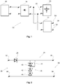
- Fig. 1 shows a schematic circuit diagram of an embodiment of the electric fence energizer system 10.
- the system 10 comprises an energizer unit 12 which can be connected with a fence by a fist terminal 14 and the ground by a second terminal 16.
- the first terminal 14 and the second terminal 16 form an output 18 of the electric fence energizer system 10.
- the energizer unit 12 generates voltage pulses which are put out through the output 18.
- the voltage pulses are generated with the energy which the electric fence energizer system 10 receives through connecting means 20 which are connected with a battery 22.
- the battery 22 comprises at least one primary cell.
- the battery 22 is connected through a charging circuit 24 with a solar module 26. With the incidence of sunlight, the solar module 26 provides electrical energy which is received by the charging circuit 24.
- the charging circuit 24 provides energy to the battery 22 which is adapted to charge the battery 22 which comprises at least one primary cell.
- Fig. 2 shows a schematic circuit diagram of the charging circuit 24 according to an embodiment of the invention.
- the charging circuit 24 comprises an input 28 and an output 30.
- the input 28 comprises a first terminal 32 to be connected with a positive pole of the solar module 26. Further, the input 28 comprises a second terminal 34 to be connected with a negative pole of the solar module 26.
- the output 30 comprises a first terminal 36 to be connected with a positive pole of the battery 22 and a second terminal 38 to be connected with a negative pole of the battery 22.
- the second terminal 34 of the input 28 and the second terminal 38 of the output 30 are connected to each other directly.
- the first terminal 32 of the input 28 and the first terminal 36 of the output 30 are connect indirectly over a diode 29 which prevents a current flowing from the battery 22 into the solar module 26.
- Three Zener diodes 40, 42, 44 which are connected serially are arranged in parallel to the terminals 36, 38 of the output 30.
- the Zener diodes 40, 42, 44 are connected in blocking direction.
- the Zener diodes 40, 42, 44 form a limiting circuit 46.
- the charging circuit 24 comprises a switch 48 for bypassing one of the Zener diodes, namely Zener diode 40.
Landscapes
- Life Sciences & Earth Sciences (AREA)
- Insects & Arthropods (AREA)
- Engineering & Computer Science (AREA)
- Power Engineering (AREA)
- Charge And Discharge Circuits For Batteries Or The Like (AREA)
- Catching Or Destruction (AREA)
Description
- The invention is directed to an electric fence energizer system, a method for this and the use of an electric fence energizer system.
- Protective fences are known for preventing animals to enter or leave a separated area. According to the state of the art, different areas which are separated by protective fences are known. For example, areas like agricultural land are separated with protective fences in order to protect the livestock grazing on the land from wild animals existing in the region. Also, protective fences are used to keep the livestock together. In particular, in the dairy industry, protective fences are utilized in order to prevent milk cows from leaving a predefined fenced area.
- Protective fences are often electrified to increase their efficiency. Further, electrification of protective fences is preferably used in agricultural areas, as construction of protective fences which are electrified can be much cheaper and faster than conventional fences because it uses plain wire and much lighter construction, as the fence does not need to physically restrain animals. The risk of injury to livestock is lower compared to fences made of barbed wire.
- It is common to refer to electrified protective fences as electric fences. Electric fences are designed to create a closed electrical circuit when touched by an animal. A component called energizer system converts power into brief high voltage pulses. One terminal of the energizer system releases one electrical pulse along a connected bare wire, for example with a minimum from one pulse per second. Another terminal is connected to a metal rod implanted in the earth, called a ground or earth rod.
- An animal touching the wire while having contact with the earth during a pulse will close an electrical circuit and will conduct the pulse, causing an electric shock. The effects of the shock depend upon the voltage and the energy of the pulse. Further, the degree of contact between the animal with the fence and the ground effects the shock. Consequently, a shock can range from barely noticeable to uncomfortable or even painful.
- Different energizer systems are known. A stationary energizer system comprises a plug which can be connected with a socket of a domestic voltage supply to receive energy for providing the pulses. Depending on the area to be fenced and remoteness of its location, mobile energizer systems are known. Mobile energizer systems are connectable to a battery or an accumulator to receive energy for providing the pulses from the energy of the battery or the accumulator. In general, it is not preferred to use accumulators instead of batteries because their voltage suddenly breaks down after a certain discharge of the accumulator.
- Thus, a mobile energizer system can be used in areas where a domestic voltage supply is not available.
- However, the capacity of a battery is not sufficient to supply the energizer systems with energy over an entire summerseason in which animals graze. Therefore, the operator must regularly check the charging status of the battery or the accumulator and replace the battery or accumulator, if necessary.
- Checking and replacing the battery or accumulator is challenging because on the one hand, a replacement of a battery which is still not unloaded causes unnecessary costs and work. On the other hand, replacement of a battery after the battery is unloaded leads to a period in which the fenced area is not electrified. Therefore, it is known from
GB 1,008,992 A FR 2 604 324 A1 - For this purpose, the invention comprises an electric fence energizer system for energizing an electric fence. The fence energizer system comprises an energizer unit which is connectable with a fence. The energizer unit preferably has an input to receive energy from an energy source and an output which is connectable to a fence to provide pulses for energizing the fence.
- Moreover, the electric fence energizer system comprises connecting means for connecting the energizer unit with a battery. In addition, the electric fence energizer system comprises a solar module for converting sunlight into electrical energy.
- Furthermore, the energizer system comprises a charging circuit. The charging circuit is adapted for receiving energy from the solar module and for providing charging energy to a battery which is connectable by the connecting means. Further, the charging circuit is adapted to provide a charging energy adapted to charge batteries comprising at least one primary cell.
- Thus, the energizer system can use a battery with a primary cell which is also called non-chargeable. Consequently, the battery is of the type which would be destroyed when connected to a solar module, directly. According to the invention, the energizer system comprises a charging circuit for proving an adapted current and/or voltage to charge such a kind of normally non-chargeable battery.
- Consequently, the battery is charged very slowly by the solar module which is no issue. In particular, the invention is based on the finding that in general, the charge of a battery is sufficient for the predominant portion of a season to provide energy for an electric fence. Thus, a low support by the solar module is sufficient for increasing the amount of charge of the battery to supply an energizer during the whole season. In addition, there is no need for an expensive accumulator which in any case has further disadvantages compared to batteries.
- According to a first embodiment, the charging circuit comprises a current and/or voltage limiting circuit to limit the current and/or voltage of the charging energy provided by the solar module for charging the battery. Thereby, the energizer system is adapted for providing a charging energy adapted to charge batteries comprising at least one primary cell. Limiting the current and/or voltage of the charging energy ensures that the battery is not destroyed during charging.
- According to a further embodiment, the current is limited by the charging circuit to a value below 0.5 Ampere during charging. Preferably, the current average is about or below 0.25 Ampere during charging. Thus, it is taken into account that the charging process is very slow, whereby this ensures that the battery is not destroyed and does not leak out.
- According to a further embodiment, the solar module provides energy up to 5 watts. A solar module which provides energy below or up to 5 watts is very cheap on the one hand. On the other hand, such a solar module with a low power output does only provide an amount of energy which can be limited with respect to its current and/or voltage by the charging circuit using cheap components in the charging circuit.
- According to a further embodiment, the charging circuit comprises at least one Zener diode. The at least one Zener diode is connected in parallel to the positive and negative terminals of the solar module in blocking direction. As a result, if the voltage of the solar module exceeds the Zener voltage, which is also called the break down voltage, current flows through the Zener diode and thus limits the current provided for charging the battery.
- According to a further embodiment, the system is adapted to charge batteries with different voltages by selectable values of current and/or voltage limits of the limiting circuit. According to a special embodiment, the charging circuit comprises at least one Zener diode and at least one further Zener diode connected in series, wherein the further Zener diode can be bypassed by closing a switch.
- Hence, by opening or closing the switch, a user can select the limiting value for limiting the current and/or voltage of the charging circuit in order to connect at least two different types of batteries which allow different maximum charging currents and/or voltages.
- According to a further embodiment, the system comprises a container for housing the battery, wherein the container is battery-acid proof. This serves for the case that a user accidentally uses the same battery in the energizer system for several years. It is known that charging a battery is only possible a few times. If a certain number of charging processes, which depends on the manufacturer, is exceeded, the battery may leak out. The container prevents the system from being damaged by acid in case of leakage.
- According to a further embodiment, the electric fence energizer system comprises a battery which is connected with the connecting means, wherein the battery is a 9-volt or 12-volt battery. Thus, the battery is part of the system.
- According to a further embodiment, at least one primary cell of the battery is of the type of at least one of Alkaline-Cell, Aluminum-Air-Cell, Chromic-Acid-Cell, Lithium-Cell, Mercury-Cell, Nickel-Oxyhydroxide-Cell, Silicon-Air-Cell, Silver-Oxide-Cell, Zinc-Air-Cell and Zinc-Carbon-Cell. The above mentioned types of batteries are available as standard components and therefore, are cheap and available in large quantity.
- According to a further embodiment, a battery which is connected with the connecting means has a capacity of about or more than 50 ampere hours, preferably more than 70 ampere hours. As an alternative of the embodiment, the system is configured to be connected to a battery with the connecting means which has a capacity of about or more than 50 ampere hours, preferably more than 70 ampere hours. Such large batteries provide sufficient energy when charged with the small charge through the solar module and the charge circuit to supply and support an electric fence over the whole season.
- Further, the invention is directed to a method for charging a battery comprising at least one primary cell with an electric fence energizer system according to any of the above-mentioned embodiments of the electric fence energizer system.
- Moreover, the invention is directed to a use of an electric fence energizer system according to any of the above-mentioned embodiments to charge and support a battery comprising at least one primary cell.
- Further features and advantages of the invention arise from the following description of preferred embodiments, wherein reference is made to the drawings:
- Fig. 1
- shows a schematic circuit diagram of the electric fence energizer system and
- Fig. 2
- shows a schematic circuit diagram of the charging circuit.
-
Fig. 1 shows a schematic circuit diagram of an embodiment of the electricfence energizer system 10. Thesystem 10 comprises anenergizer unit 12 which can be connected with a fence by afist terminal 14 and the ground by asecond terminal 16. Thefirst terminal 14 and thesecond terminal 16 form anoutput 18 of the electricfence energizer system 10. - The
energizer unit 12 generates voltage pulses which are put out through theoutput 18. The voltage pulses are generated with the energy which the electricfence energizer system 10 receives through connectingmeans 20 which are connected with abattery 22. Thebattery 22 comprises at least one primary cell. - Moreover, the
battery 22 is connected through a chargingcircuit 24 with asolar module 26. With the incidence of sunlight, thesolar module 26 provides electrical energy which is received by the chargingcircuit 24. The chargingcircuit 24 provides energy to thebattery 22 which is adapted to charge thebattery 22 which comprises at least one primary cell. -
Fig. 2 shows a schematic circuit diagram of the chargingcircuit 24 according to an embodiment of the invention. The chargingcircuit 24 comprises aninput 28 and anoutput 30. - The
input 28 comprises afirst terminal 32 to be connected with a positive pole of thesolar module 26. Further, theinput 28 comprises asecond terminal 34 to be connected with a negative pole of thesolar module 26. Theoutput 30 comprises afirst terminal 36 to be connected with a positive pole of thebattery 22 and asecond terminal 38 to be connected with a negative pole of thebattery 22. - The
second terminal 34 of theinput 28 and thesecond terminal 38 of theoutput 30 are connected to each other directly. Thefirst terminal 32 of theinput 28 and thefirst terminal 36 of theoutput 30 are connect indirectly over adiode 29 which prevents a current flowing from thebattery 22 into thesolar module 26. ThreeZener diodes terminals output 30. TheZener diodes Zener diodes circuit 46. - Further, the charging
circuit 24 comprises aswitch 48 for bypassing one of the Zener diodes, namelyZener diode 40. - Thus, if the
switch 48 is open and if the voltage of thesolar module 26 exceeds the Zener voltage of the threediodes Zener diodes battery 22. - In case the
switch 48 is closed, current flows through theZener diodes battery 22 if the voltage of thesolar module 26 exceeds the Zener voltage of the twodiodes switch 48, a user can select the limiting value for limiting the current and/or voltage of the chargingcircuit 24 in order to connect at least two different types of batteries which allow different maximum charging currents or voltages. -
- 10
- electric fence energizer system
- 12
- energizer unit
- 14
- first terminal
- 16
- second terminal
- 18
- output of the system
- 20
- connecting means
- 22
- battery
- 24
- charging circuit
- 26
- solar module
- 28
- input of the charging circuit
- 29
- diode
- 30
- output of the charging circuit
- 32
- first terminal of input of the charging circuit
- 34
- second terminal of input of the charging circuit
- 36
- first terminal of output of the charging circuit
- 38
- second terminal of output of the charging circuit
- 40
- Zener diode
- 42
- Zener diode
- 44
- Zener diode
- 46
- limiting circuit
- 48
- switch
Claims (13)
- Electric fence energizer system (10) for energizing an electric fence comprising:- an energizer unit (12) connectable with a fence,- connecting means (20) for connecting the energizer (12) unit with a battery (22),- a solar module (26) for converting sunlight into electrical energy and- a charging circuit (24) for receiving energy from the solar module (26) and for providing charging energy to a battery (22) which is connectable by the connecting means (20), characterized in that the charging circuit (24) is adapted to provide a charging energy adapted to charge batteries (22) comprising at least one primary cell.
- Electric fence energizer system according to claim 1, wherein for providing a charging energy adapted to charge batteries (22) comprising at least one primary cell, the charging circuit (24) comprises a current and/or voltage limiting circuit (46) to limit the current of the charging energy provided by the solar module (26).
- Electric fence energizer system according to claim 1 or 2, wherein the charging circuit (24) is adapted to limit the current which is received from the solar module (26) to a value below 0.5 Ampere, preferable the current average is about or below 0.25 Ampere.
- Electric fence energizer system according to any of the preceding claims, wherein the solar module (26) provides energy up to 5 watts.
- Electric fence energizer system according to any of the preceding claims, wherein the charging circuit (24) comprises at least one Zener diode (42, 44).
- Electric fence energizer system according to any of the preceding claims, wherein the charging circuit (24) comprises at least one Zener diode (42, 44) and at least one further Zener diode (40) connected in series, wherein the further Zener (40) diode can be bypassed by closing a switch (48).
- Electric fence energizer system according to any of the preceding claims, wherein the system (10) comprises a container for housing the battery (22), wherein the container is battery acid proof.
- Electric fence energizer system according to any of the preceding claims, wherein the system (10) is adapted to charge batteries (22) with different voltages by selectable values of current and/or voltage limits of the limiting circuit.
- Electric fence energizer system according to any of the preceding claims, wherein the system (10) comprises a battery (22) which is connected with the connecting means (20), wherein the battery is a 9-volt or 12-volt battery.
- Electric fence energizer system according to claim 9, wherein the at least one primary cell of the battery (22) is of the type of at least one of Alkaline-Cell, Aluminum-Air-Cell, Chromic-Acid-Cell, Lithium-Cell, Mercury-Cell, Nickel-Oxyhydroxide-Cell, Silicon-Air-Cell, Silver-Oxide-Cell, Zinc-Air-Cell and Zinc-Carbon-Cell.
- Electric fence energizer system according to any of the preceding claims, wherein a battery (22) which is connected with the connecting means (20) has a capacity of about or more than 50 ampere hours, preferably more than 70 ampere hours, or
wherein the system (10) is configured to be connected to a battery (22) with the connecting means (20) which has a capacity of about or more than 50 ampere hours, preferably more than 70 ampere hours. - Method for charging a battery (22) comprising at least one primary cell with an electric fence energizer system (10) according to any of the preceding claims.
- Use of an electric fence energizer system (10) according to any of the claims 1 to 11 to charge a battery (22) comprising at least one primary cell.
Priority Applications (1)
| Application Number | Priority Date | Filing Date | Title |
|---|---|---|---|
| EP17205700.2A EP3496514B1 (en) | 2017-12-06 | 2017-12-06 | Electric fence energizer system and method |
Applications Claiming Priority (1)
| Application Number | Priority Date | Filing Date | Title |
|---|---|---|---|
| EP17205700.2A EP3496514B1 (en) | 2017-12-06 | 2017-12-06 | Electric fence energizer system and method |
Publications (2)
| Publication Number | Publication Date |
|---|---|
| EP3496514A1 EP3496514A1 (en) | 2019-06-12 |
| EP3496514B1 true EP3496514B1 (en) | 2021-02-03 |
Family
ID=60629477
Family Applications (1)
| Application Number | Title | Priority Date | Filing Date |
|---|---|---|---|
| EP17205700.2A Active EP3496514B1 (en) | 2017-12-06 | 2017-12-06 | Electric fence energizer system and method |
Country Status (1)
| Country | Link |
|---|---|
| EP (1) | EP3496514B1 (en) |
Families Citing this family (2)
| Publication number | Priority date | Publication date | Assignee | Title |
|---|---|---|---|---|
| DE102023123106A1 (en) | 2023-08-28 | 2025-03-06 | Bernd Achgelis | agri-photovoltaic system |
| DE202023104894U1 (en) | 2023-08-28 | 2023-09-30 | Bernd Achgelis | Agri-photovoltaic system |
Family Cites Families (4)
| Publication number | Priority date | Publication date | Assignee | Title |
|---|---|---|---|---|
| GB1008992A (en) * | 1962-07-24 | 1965-11-03 | British Telecomm Res Ltd | Improvements in or relating to electric fences |
| JPS5778238U (en) * | 1981-10-19 | 1982-05-14 | ||
| FR2604324A1 (en) * | 1986-09-22 | 1988-03-25 | Egea Remy | Sensitive electric fence |
| JPH07130400A (en) * | 1993-11-02 | 1995-05-19 | Fuji Photo Film Co Ltd | Non-aqueous electrolyte battery charging method and charging device |
-
2017
- 2017-12-06 EP EP17205700.2A patent/EP3496514B1/en active Active
Also Published As
| Publication number | Publication date |
|---|---|
| EP3496514A1 (en) | 2019-06-12 |
Similar Documents
| Publication | Publication Date | Title |
|---|---|---|
| Osaretin et al. | Design and implementation of a solar charge controller with variable output | |
| US10825937B2 (en) | Protective circuit for a photovoltaic (PV) module, method for operating the protective circuit, and photovoltaic (PV) system having such a protective circuit | |
| EP2441113B1 (en) | System for preventing deep battery discharge | |
| US20140293491A1 (en) | Active Bypass Diode Circuit and Solar Power Module with Arc Flash Mitigation Feature | |
| JP2009033892A (en) | Independent power system | |
| US6020658A (en) | Electric fence energizer | |
| EP3496514A1 (en) | Electric fence energizer system and method | |
| CA2710758A1 (en) | Method and system for float charging a battery | |
| KR20120074214A (en) | Protective circuit and charging device | |
| WO2016149440A1 (en) | Buck pre-charger for series-connected battery modules | |
| US4311952A (en) | Battery charging system | |
| SE439405B (en) | METHOD OF CHARGING AN ELECTRIC ACCUMULATOR BATTERY BY SOLAR PANELS CONTAINING SOLAR CELLS, AND DEVICE FOR CHARGING ACCORDING TO THE METHOD | |
| CN101764395B (en) | Lead-acid battery under-voltage protection method and power management system | |
| US10018678B2 (en) | Method and device for measuring a battery cell current | |
| RU2374734C2 (en) | Guard circuit for sparkproof electromagnetic actuators and guard circuit for sparkproof electric power systems | |
| KR101057631B1 (en) | Electric fence using solar cell and its driving method | |
| US7944669B2 (en) | Electric fence energizer lightning protection | |
| US9385541B2 (en) | Universal fast charger for any rechargeable electrolytic element, alkaline batteries and accumulators | |
| JP4012073B2 (en) | Power supply | |
| CN106972574B (en) | Vehicle-mounted charging and discharging circuit with protection function for lithium battery | |
| Yunus et al. | IoT-based intelligent system for farm electric fence | |
| Kumar et al. | Design and implementation of solar charge controller for photovoltaic systems | |
| CN103944232A (en) | Lithium battery pack overdischarge protective circuit of underwater robot | |
| AU2002255146A1 (en) | Power supply | |
| US6803742B1 (en) | Solar rechargeable battery |
Legal Events
| Date | Code | Title | Description |
|---|---|---|---|
| PUAI | Public reference made under article 153(3) epc to a published international application that has entered the european phase |
Free format text: ORIGINAL CODE: 0009012 |
|
| STAA | Information on the status of an ep patent application or granted ep patent |
Free format text: STATUS: THE APPLICATION HAS BEEN PUBLISHED |
|
| AK | Designated contracting states |
Kind code of ref document: A1 Designated state(s): AL AT BE BG CH CY CZ DE DK EE ES FI FR GB GR HR HU IE IS IT LI LT LU LV MC MK MT NL NO PL PT RO RS SE SI SK SM TR |
|
| AX | Request for extension of the european patent |
Extension state: BA ME |
|
| STAA | Information on the status of an ep patent application or granted ep patent |
Free format text: STATUS: REQUEST FOR EXAMINATION WAS MADE |
|
| 17P | Request for examination filed |
Effective date: 20191212 |
|
| RBV | Designated contracting states (corrected) |
Designated state(s): AL AT BE BG CH CY CZ DE DK EE ES FI FR GB GR HR HU IE IS IT LI LT LU LV MC MK MT NL NO PL PT RO RS SE SI SK SM TR |
|
| GRAP | Despatch of communication of intention to grant a patent |
Free format text: ORIGINAL CODE: EPIDOSNIGR1 |
|
| STAA | Information on the status of an ep patent application or granted ep patent |
Free format text: STATUS: GRANT OF PATENT IS INTENDED |
|
| RIC1 | Information provided on ipc code assigned before grant |
Ipc: H05C 1/04 20060101ALI20200824BHEP Ipc: H05C 1/00 20060101AFI20200824BHEP Ipc: H02J 7/35 20060101ALI20200824BHEP |
|
| INTG | Intention to grant announced |
Effective date: 20200917 |
|
| GRAS | Grant fee paid |
Free format text: ORIGINAL CODE: EPIDOSNIGR3 |
|
| GRAA | (expected) grant |
Free format text: ORIGINAL CODE: 0009210 |
|
| STAA | Information on the status of an ep patent application or granted ep patent |
Free format text: STATUS: THE PATENT HAS BEEN GRANTED |
|
| AK | Designated contracting states |
Kind code of ref document: B1 Designated state(s): AL AT BE BG CH CY CZ DE DK EE ES FI FR GB GR HR HU IE IS IT LI LT LU LV MC MK MT NL NO PL PT RO RS SE SI SK SM TR |
|
| REG | Reference to a national code |
Ref country code: GB Ref legal event code: FG4D |
|
| REG | Reference to a national code |
Ref country code: AT Ref legal event code: REF Ref document number: 1360015 Country of ref document: AT Kind code of ref document: T Effective date: 20210215 Ref country code: CH Ref legal event code: NV Representative=s name: E. BLUM AND CO. AG PATENT- UND MARKENANWAELTE , CH Ref country code: CH Ref legal event code: EP |
|
| REG | Reference to a national code |
Ref country code: DE Ref legal event code: R096 Ref document number: 602017032332 Country of ref document: DE |
|
| REG | Reference to a national code |
Ref country code: IE Ref legal event code: FG4D |
|
| REG | Reference to a national code |
Ref country code: NL Ref legal event code: FP |
|
| REG | Reference to a national code |
Ref country code: LT Ref legal event code: MG9D |
|
| REG | Reference to a national code |
Ref country code: AT Ref legal event code: MK05 Ref document number: 1360015 Country of ref document: AT Kind code of ref document: T Effective date: 20210203 |
|
| PG25 | Lapsed in a contracting state [announced via postgrant information from national office to epo] |
Ref country code: FI Free format text: LAPSE BECAUSE OF FAILURE TO SUBMIT A TRANSLATION OF THE DESCRIPTION OR TO PAY THE FEE WITHIN THE PRESCRIBED TIME-LIMIT Effective date: 20210203 Ref country code: HR Free format text: LAPSE BECAUSE OF FAILURE TO SUBMIT A TRANSLATION OF THE DESCRIPTION OR TO PAY THE FEE WITHIN THE PRESCRIBED TIME-LIMIT Effective date: 20210203 Ref country code: GR Free format text: LAPSE BECAUSE OF FAILURE TO SUBMIT A TRANSLATION OF THE DESCRIPTION OR TO PAY THE FEE WITHIN THE PRESCRIBED TIME-LIMIT Effective date: 20210504 Ref country code: PT Free format text: LAPSE BECAUSE OF FAILURE TO SUBMIT A TRANSLATION OF THE DESCRIPTION OR TO PAY THE FEE WITHIN THE PRESCRIBED TIME-LIMIT Effective date: 20210604 Ref country code: NO Free format text: LAPSE BECAUSE OF FAILURE TO SUBMIT A TRANSLATION OF THE DESCRIPTION OR TO PAY THE FEE WITHIN THE PRESCRIBED TIME-LIMIT Effective date: 20210503 Ref country code: BG Free format text: LAPSE BECAUSE OF FAILURE TO SUBMIT A TRANSLATION OF THE DESCRIPTION OR TO PAY THE FEE WITHIN THE PRESCRIBED TIME-LIMIT Effective date: 20210503 Ref country code: LT Free format text: LAPSE BECAUSE OF FAILURE TO SUBMIT A TRANSLATION OF THE DESCRIPTION OR TO PAY THE FEE WITHIN THE PRESCRIBED TIME-LIMIT Effective date: 20210203 |
|
| PG25 | Lapsed in a contracting state [announced via postgrant information from national office to epo] |
Ref country code: SE Free format text: LAPSE BECAUSE OF FAILURE TO SUBMIT A TRANSLATION OF THE DESCRIPTION OR TO PAY THE FEE WITHIN THE PRESCRIBED TIME-LIMIT Effective date: 20210203 Ref country code: AT Free format text: LAPSE BECAUSE OF FAILURE TO SUBMIT A TRANSLATION OF THE DESCRIPTION OR TO PAY THE FEE WITHIN THE PRESCRIBED TIME-LIMIT Effective date: 20210203 Ref country code: LV Free format text: LAPSE BECAUSE OF FAILURE TO SUBMIT A TRANSLATION OF THE DESCRIPTION OR TO PAY THE FEE WITHIN THE PRESCRIBED TIME-LIMIT Effective date: 20210203 Ref country code: PL Free format text: LAPSE BECAUSE OF FAILURE TO SUBMIT A TRANSLATION OF THE DESCRIPTION OR TO PAY THE FEE WITHIN THE PRESCRIBED TIME-LIMIT Effective date: 20210203 Ref country code: RS Free format text: LAPSE BECAUSE OF FAILURE TO SUBMIT A TRANSLATION OF THE DESCRIPTION OR TO PAY THE FEE WITHIN THE PRESCRIBED TIME-LIMIT Effective date: 20210203 |
|
| PG25 | Lapsed in a contracting state [announced via postgrant information from national office to epo] |
Ref country code: IS Free format text: LAPSE BECAUSE OF FAILURE TO SUBMIT A TRANSLATION OF THE DESCRIPTION OR TO PAY THE FEE WITHIN THE PRESCRIBED TIME-LIMIT Effective date: 20210603 |
|
| PG25 | Lapsed in a contracting state [announced via postgrant information from national office to epo] |
Ref country code: SM Free format text: LAPSE BECAUSE OF FAILURE TO SUBMIT A TRANSLATION OF THE DESCRIPTION OR TO PAY THE FEE WITHIN THE PRESCRIBED TIME-LIMIT Effective date: 20210203 Ref country code: EE Free format text: LAPSE BECAUSE OF FAILURE TO SUBMIT A TRANSLATION OF THE DESCRIPTION OR TO PAY THE FEE WITHIN THE PRESCRIBED TIME-LIMIT Effective date: 20210203 Ref country code: CZ Free format text: LAPSE BECAUSE OF FAILURE TO SUBMIT A TRANSLATION OF THE DESCRIPTION OR TO PAY THE FEE WITHIN THE PRESCRIBED TIME-LIMIT Effective date: 20210203 |
|
| REG | Reference to a national code |
Ref country code: DE Ref legal event code: R097 Ref document number: 602017032332 Country of ref document: DE |
|
| PG25 | Lapsed in a contracting state [announced via postgrant information from national office to epo] |
Ref country code: SK Free format text: LAPSE BECAUSE OF FAILURE TO SUBMIT A TRANSLATION OF THE DESCRIPTION OR TO PAY THE FEE WITHIN THE PRESCRIBED TIME-LIMIT Effective date: 20210203 Ref country code: RO Free format text: LAPSE BECAUSE OF FAILURE TO SUBMIT A TRANSLATION OF THE DESCRIPTION OR TO PAY THE FEE WITHIN THE PRESCRIBED TIME-LIMIT Effective date: 20210203 Ref country code: DK Free format text: LAPSE BECAUSE OF FAILURE TO SUBMIT A TRANSLATION OF THE DESCRIPTION OR TO PAY THE FEE WITHIN THE PRESCRIBED TIME-LIMIT Effective date: 20210203 |
|
| PLBE | No opposition filed within time limit |
Free format text: ORIGINAL CODE: 0009261 |
|
| STAA | Information on the status of an ep patent application or granted ep patent |
Free format text: STATUS: NO OPPOSITION FILED WITHIN TIME LIMIT |
|
| 26N | No opposition filed |
Effective date: 20211104 |
|
| PG25 | Lapsed in a contracting state [announced via postgrant information from national office to epo] |
Ref country code: AL Free format text: LAPSE BECAUSE OF FAILURE TO SUBMIT A TRANSLATION OF THE DESCRIPTION OR TO PAY THE FEE WITHIN THE PRESCRIBED TIME-LIMIT Effective date: 20210203 Ref country code: ES Free format text: LAPSE BECAUSE OF FAILURE TO SUBMIT A TRANSLATION OF THE DESCRIPTION OR TO PAY THE FEE WITHIN THE PRESCRIBED TIME-LIMIT Effective date: 20210203 |
|
| PG25 | Lapsed in a contracting state [announced via postgrant information from national office to epo] |
Ref country code: SI Free format text: LAPSE BECAUSE OF FAILURE TO SUBMIT A TRANSLATION OF THE DESCRIPTION OR TO PAY THE FEE WITHIN THE PRESCRIBED TIME-LIMIT Effective date: 20210203 |
|
| PG25 | Lapsed in a contracting state [announced via postgrant information from national office to epo] |
Ref country code: IT Free format text: LAPSE BECAUSE OF FAILURE TO SUBMIT A TRANSLATION OF THE DESCRIPTION OR TO PAY THE FEE WITHIN THE PRESCRIBED TIME-LIMIT Effective date: 20210203 |
|
| PG25 | Lapsed in a contracting state [announced via postgrant information from national office to epo] |
Ref country code: IS Free format text: LAPSE BECAUSE OF FAILURE TO SUBMIT A TRANSLATION OF THE DESCRIPTION OR TO PAY THE FEE WITHIN THE PRESCRIBED TIME-LIMIT Effective date: 20210603 |
|
| PG25 | Lapsed in a contracting state [announced via postgrant information from national office to epo] |
Ref country code: MC Free format text: LAPSE BECAUSE OF FAILURE TO SUBMIT A TRANSLATION OF THE DESCRIPTION OR TO PAY THE FEE WITHIN THE PRESCRIBED TIME-LIMIT Effective date: 20210203 |
|
| REG | Reference to a national code |
Ref country code: BE Ref legal event code: MM Effective date: 20211231 |
|
| PG25 | Lapsed in a contracting state [announced via postgrant information from national office to epo] |
Ref country code: LU Free format text: LAPSE BECAUSE OF NON-PAYMENT OF DUE FEES Effective date: 20211206 Ref country code: IE Free format text: LAPSE BECAUSE OF NON-PAYMENT OF DUE FEES Effective date: 20211206 |
|
| PG25 | Lapsed in a contracting state [announced via postgrant information from national office to epo] |
Ref country code: BE Free format text: LAPSE BECAUSE OF NON-PAYMENT OF DUE FEES Effective date: 20211231 |
|
| PG25 | Lapsed in a contracting state [announced via postgrant information from national office to epo] |
Ref country code: CY Free format text: LAPSE BECAUSE OF FAILURE TO SUBMIT A TRANSLATION OF THE DESCRIPTION OR TO PAY THE FEE WITHIN THE PRESCRIBED TIME-LIMIT Effective date: 20210203 |
|
| PG25 | Lapsed in a contracting state [announced via postgrant information from national office to epo] |
Ref country code: HU Free format text: LAPSE BECAUSE OF FAILURE TO SUBMIT A TRANSLATION OF THE DESCRIPTION OR TO PAY THE FEE WITHIN THE PRESCRIBED TIME-LIMIT; INVALID AB INITIO Effective date: 20171206 |
|
| PG25 | Lapsed in a contracting state [announced via postgrant information from national office to epo] |
Ref country code: MK Free format text: LAPSE BECAUSE OF FAILURE TO SUBMIT A TRANSLATION OF THE DESCRIPTION OR TO PAY THE FEE WITHIN THE PRESCRIBED TIME-LIMIT Effective date: 20210203 |
|
| PG25 | Lapsed in a contracting state [announced via postgrant information from national office to epo] |
Ref country code: MT Free format text: LAPSE BECAUSE OF FAILURE TO SUBMIT A TRANSLATION OF THE DESCRIPTION OR TO PAY THE FEE WITHIN THE PRESCRIBED TIME-LIMIT Effective date: 20210203 |
|
| PGFP | Annual fee paid to national office [announced via postgrant information from national office to epo] |
Ref country code: NL Payment date: 20241217 Year of fee payment: 8 |
|
| PGFP | Annual fee paid to national office [announced via postgrant information from national office to epo] |
Ref country code: GB Payment date: 20241218 Year of fee payment: 8 |
|
| PGFP | Annual fee paid to national office [announced via postgrant information from national office to epo] |
Ref country code: FR Payment date: 20241217 Year of fee payment: 8 |
|
| PGFP | Annual fee paid to national office [announced via postgrant information from national office to epo] |
Ref country code: DE Payment date: 20250120 Year of fee payment: 8 |
|
| PGFP | Annual fee paid to national office [announced via postgrant information from national office to epo] |
Ref country code: CH Payment date: 20250101 Year of fee payment: 8 |
|
| PG25 | Lapsed in a contracting state [announced via postgrant information from national office to epo] |
Ref country code: TR Free format text: LAPSE BECAUSE OF FAILURE TO SUBMIT A TRANSLATION OF THE DESCRIPTION OR TO PAY THE FEE WITHIN THE PRESCRIBED TIME-LIMIT Effective date: 20210203 |