EP3496247A1 - Stator core and motor - Google Patents
Stator core and motor Download PDFInfo
- Publication number
- EP3496247A1 EP3496247A1 EP17837089.6A EP17837089A EP3496247A1 EP 3496247 A1 EP3496247 A1 EP 3496247A1 EP 17837089 A EP17837089 A EP 17837089A EP 3496247 A1 EP3496247 A1 EP 3496247A1
- Authority
- EP
- European Patent Office
- Prior art keywords
- ratio
- magnet
- rotor
- motor
- teeth
- Prior art date
- Legal status (The legal status is an assumption and is not a legal conclusion. Google has not performed a legal analysis and makes no representation as to the accuracy of the status listed.)
- Withdrawn
Links
- 230000002093 peripheral effect Effects 0.000 claims abstract description 40
- 238000004088 simulation Methods 0.000 description 8
- 238000010586 diagram Methods 0.000 description 7
- 230000003247 decreasing effect Effects 0.000 description 6
- 239000012212 insulator Substances 0.000 description 4
- 229910052751 metal Inorganic materials 0.000 description 3
- 239000002184 metal Substances 0.000 description 3
- 238000004804 winding Methods 0.000 description 3
- 230000000052 comparative effect Effects 0.000 description 2
- 230000000694 effects Effects 0.000 description 2
- 229910000838 Al alloy Inorganic materials 0.000 description 1
- 238000001816 cooling Methods 0.000 description 1
- 230000005484 gravity Effects 0.000 description 1
- 238000000034 method Methods 0.000 description 1
- 238000012986 modification Methods 0.000 description 1
- 230000004048 modification Effects 0.000 description 1
- 238000000465 moulding Methods 0.000 description 1
- 230000005405 multipole Effects 0.000 description 1
- 239000011347 resin Substances 0.000 description 1
- 229920005989 resin Polymers 0.000 description 1
Images




Classifications
-
- H—ELECTRICITY
- H02—GENERATION; CONVERSION OR DISTRIBUTION OF ELECTRIC POWER
- H02K—DYNAMO-ELECTRIC MACHINES
- H02K7/00—Arrangements for handling mechanical energy structurally associated with dynamo-electric machines, e.g. structural association with mechanical driving motors or auxiliary dynamo-electric machines
- H02K7/14—Structural association with mechanical loads, e.g. with hand-held machine tools or fans
-
- H—ELECTRICITY
- H02—GENERATION; CONVERSION OR DISTRIBUTION OF ELECTRIC POWER
- H02K—DYNAMO-ELECTRIC MACHINES
- H02K1/00—Details of the magnetic circuit
- H02K1/06—Details of the magnetic circuit characterised by the shape, form or construction
- H02K1/12—Stationary parts of the magnetic circuit
- H02K1/14—Stator cores with salient poles
-
- H—ELECTRICITY
- H02—GENERATION; CONVERSION OR DISTRIBUTION OF ELECTRIC POWER
- H02K—DYNAMO-ELECTRIC MACHINES
- H02K1/00—Details of the magnetic circuit
- H02K1/06—Details of the magnetic circuit characterised by the shape, form or construction
- H02K1/12—Stationary parts of the magnetic circuit
- H02K1/14—Stator cores with salient poles
- H02K1/146—Stator cores with salient poles consisting of a generally annular yoke with salient poles
-
- H—ELECTRICITY
- H02—GENERATION; CONVERSION OR DISTRIBUTION OF ELECTRIC POWER
- H02K—DYNAMO-ELECTRIC MACHINES
- H02K1/00—Details of the magnetic circuit
- H02K1/06—Details of the magnetic circuit characterised by the shape, form or construction
- H02K1/12—Stationary parts of the magnetic circuit
- H02K1/16—Stator cores with slots for windings
- H02K1/165—Shape, form or location of the slots
-
- H—ELECTRICITY
- H02—GENERATION; CONVERSION OR DISTRIBUTION OF ELECTRIC POWER
- H02K—DYNAMO-ELECTRIC MACHINES
- H02K1/00—Details of the magnetic circuit
- H02K1/06—Details of the magnetic circuit characterised by the shape, form or construction
- H02K1/22—Rotating parts of the magnetic circuit
- H02K1/27—Rotor cores with permanent magnets
- H02K1/2706—Inner rotors
- H02K1/272—Inner rotors the magnetisation axis of the magnets being perpendicular to the rotor axis
- H02K1/274—Inner rotors the magnetisation axis of the magnets being perpendicular to the rotor axis the rotor consisting of two or more circumferentially positioned magnets
- H02K1/2753—Inner rotors the magnetisation axis of the magnets being perpendicular to the rotor axis the rotor consisting of two or more circumferentially positioned magnets the rotor consisting of magnets or groups of magnets arranged with alternating polarity
- H02K1/278—Surface mounted magnets; Inset magnets
-
- H—ELECTRICITY
- H02—GENERATION; CONVERSION OR DISTRIBUTION OF ELECTRIC POWER
- H02K—DYNAMO-ELECTRIC MACHINES
- H02K1/00—Details of the magnetic circuit
- H02K1/06—Details of the magnetic circuit characterised by the shape, form or construction
- H02K1/22—Rotating parts of the magnetic circuit
- H02K1/27—Rotor cores with permanent magnets
- H02K1/2786—Outer rotors
- H02K1/2787—Outer rotors the magnetisation axis of the magnets being perpendicular to the rotor axis
- H02K1/2789—Outer rotors the magnetisation axis of the magnets being perpendicular to the rotor axis the rotor consisting of two or more circumferentially positioned magnets
- H02K1/2791—Surface mounted magnets; Inset magnets
-
- H—ELECTRICITY
- H02—GENERATION; CONVERSION OR DISTRIBUTION OF ELECTRIC POWER
- H02K—DYNAMO-ELECTRIC MACHINES
- H02K21/00—Synchronous motors having permanent magnets; Synchronous generators having permanent magnets
- H02K21/12—Synchronous motors having permanent magnets; Synchronous generators having permanent magnets with stationary armatures and rotating magnets
- H02K21/14—Synchronous motors having permanent magnets; Synchronous generators having permanent magnets with stationary armatures and rotating magnets with magnets rotating within the armatures
- H02K21/16—Synchronous motors having permanent magnets; Synchronous generators having permanent magnets with stationary armatures and rotating magnets with magnets rotating within the armatures having annular armature cores with salient poles
-
- H—ELECTRICITY
- H02—GENERATION; CONVERSION OR DISTRIBUTION OF ELECTRIC POWER
- H02K—DYNAMO-ELECTRIC MACHINES
- H02K21/00—Synchronous motors having permanent magnets; Synchronous generators having permanent magnets
- H02K21/12—Synchronous motors having permanent magnets; Synchronous generators having permanent magnets with stationary armatures and rotating magnets
- H02K21/22—Synchronous motors having permanent magnets; Synchronous generators having permanent magnets with stationary armatures and rotating magnets with magnets rotating around the armatures, e.g. flywheel magnetos
-
- H—ELECTRICITY
- H02—GENERATION; CONVERSION OR DISTRIBUTION OF ELECTRIC POWER
- H02K—DYNAMO-ELECTRIC MACHINES
- H02K21/00—Synchronous motors having permanent magnets; Synchronous generators having permanent magnets
- H02K21/12—Synchronous motors having permanent magnets; Synchronous generators having permanent magnets with stationary armatures and rotating magnets
- H02K21/22—Synchronous motors having permanent magnets; Synchronous generators having permanent magnets with stationary armatures and rotating magnets with magnets rotating around the armatures, e.g. flywheel magnetos
- H02K21/227—Synchronous motors having permanent magnets; Synchronous generators having permanent magnets with stationary armatures and rotating magnets with magnets rotating around the armatures, e.g. flywheel magnetos having an annular armature coil
-
- H—ELECTRICITY
- H02—GENERATION; CONVERSION OR DISTRIBUTION OF ELECTRIC POWER
- H02K—DYNAMO-ELECTRIC MACHINES
- H02K29/00—Motors or generators having non-mechanical commutating devices, e.g. discharge tubes or semiconductor devices
- H02K29/03—Motors or generators having non-mechanical commutating devices, e.g. discharge tubes or semiconductor devices with a magnetic circuit specially adapted for avoiding torque ripples or self-starting problems
-
- H—ELECTRICITY
- H02—GENERATION; CONVERSION OR DISTRIBUTION OF ELECTRIC POWER
- H02K—DYNAMO-ELECTRIC MACHINES
- H02K2213/00—Specific aspects, not otherwise provided for and not covered by codes H02K2201/00 - H02K2211/00
- H02K2213/03—Machines characterised by numerical values, ranges, mathematical expressions or similar information
Definitions
- the present invention relates to a stator core, and a motor including the stator core.
- a technique for reducing cogging torque has been proposed for a brushless motor.
- a brushless motor 1 disclosed in Japanese Unexamined Patent Application Publication No. 2014-230444 a protrusion portion 12 is provided at a center of a pole tooth portion 9 of each salient pole 8 of a stator core 6, and a pair of notch portions 13 is provided on both sides of the protrusion portion 12. Accordingly, the cogging torque of the brushless motor 1 is reduced.
- a motor having a large number of poles and slots is used for increasing an output torque of the motor. Even in such a multi-pole and multi-slot motor, it is required to reduce a cogging torque while suppressing reduction in the output torque of the motor.
- the present invention is made to reduce a cogging torque with consideration of the challenges stated above.
- An exemplified stator core includes an annular core back portion; and a plurality of teeth extending radially from the core back portion to a rotor magnet having a plurality of magnets.
- a ratio of the number of slots which is the number of the plurality of teeth to the number of poles which is the number of the plurality of magnets of the rotor magnet is 3:4.
- a slot open ratio which is a ratio of a slot open angle between two adjacent teeth in a peripheral direction to an angle between center lines of the two teeth is 0.5 or more.
- Fig. 1 is a perspective view showing an appearance of a motor 1 according to one exemplary embodiment of the present invention.
- the motor 1 is an external rotor brushless motor.
- the motor 1 is used to, for example, rotate an impeller in an axial flow fan.
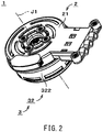
- Fig. 2 is a perspective view of the motor 1 as viewed from a direction different from that of Fig. 1 .
- Fig. 3 is a longitudinal cross-sectional view of the motor 1. Parallel slanting lines in the detailed cross-section are omitted in Fig. 3 .
- a configuration on a far side from the cross-section and a partial outer surface of the motor are also drawn in Fig. 3 .
- an upper side and a lower side in a direction of a center axis J1 of the motor 1 in Fig. 3 are simply referred to as an "upper side” and a “lower side”, respectively.
- the upper and lower sides in this specification do not indicate upper and lower sides in a gravity direction when installed into the actual equipment.
- a peripheral direction around the center axis J1 is simply referred to as a "peripheral direction”
- a radial direction around the center axis J1 is simply referred to as a “radial direction.”
- a direction parallel to the center axis J1 is referred to as a "vertical direction” or an "axial direction.”
- the motor 1 includes a stationary portion 2, a rotating portion 3, and a bearing mechanism 4.
- the bearing mechanism 4 rotatably supports the rotating portion 3 with respect to the stationary portion 2.
- the stationary portion 2 includes a bracket 21, an armature 22, and a bus bar unit 26.
- the rotating portion 3 includes a shaft 31 and a rotor 32.
- the bearing mechanism 4 includes a lower ball bearing 41 and an upper ball bearing 42.
- the bracket 21 includes the cylindrical portion 212.
- the cylindrical portion 212 is a substantially cylindrical portion centered on the center axis J1 oriented in the vertical direction.
- the bearing mechanism 4 is fixed to an inner peripheral surface of the cylindrical portion 212 of the bracket 21.
- the lower ball bearing 41 of the bearing mechanism 4 is fixed to an inner peripheral surface of a lower portion of the cylindrical portion 212.
- the upper ball bearing 42 is fixed to an inner peripheral surface of an upper portion of the cylindrical portion 212.
- the armature 22 is fixed to an outer peripheral surface of the cylindrical portion 212 of the bracket 21.
- the armature 22 is disposed radially outward of the bearing mechanism 4.
- the armature 22 is electrically connected to the bus bar unit 26.
- the armature 22 is electrically connected to an external power supply (not shown) via the bus bar unit 26.
- the armature 22 includes a stator core 220, an insulator 223, and a plurality of coils 224.
- the stator core 220 includes a core back portion 221 and a plurality of teeth 222.
- the insulator 223 is an insulator covering surfaces of the plurality of teeth 222.
- the plurality of coils 224 are formed by winding a conductive wire from above the insulator 223 to the plurality of teeth 222. In this embodiment, the plurality of coil 224 are three-phase coils.
- Fig. 4 is a plan view of the stator core 220.
- the core back portion 221 is an annular portion centered on the center axis J1.
- the core back portion 221 is fixed to the outer peripheral surface of the cylindrical portion 212 of the bracket 21.
- the plurality of teeth 222 eradiate radially outward from the core back portion 221.
- the plurality of teeth 222 are arranged at substantially equal angular intervals in the peripheral direction.
- Each tooth 222 includes a tooth body portion 226 and a tooth tip portion 227.
- the tooth body portion 226 extends substantially linearly and radially outward from the core back portion 221.
- the tooth tip portion 227 extends to both peripheral sides from a radial outer end portion of the tooth body portion 226.
- the core back portion 221 and the plurality of teeth 222 are, for example, a single member made of metal.
- the number of slots which is the number of the plurality of teeth 222, is 18.
- An angle ⁇ 1 in the peripheral direction between center lines of two adjacent teeth 222 in the peripheral direction is 20 degrees.
- the center line of the tooth 222 is a straight line passing through the center axis J1 and a center in the peripheral direction of the tooth 222 in a plan view.
- the angle ⁇ 1 is referred to as an "inter-teeth angle ⁇ 1.”
- the angle ⁇ 2 in the peripheral direction of a slot open between the two adjacent teeth 222 in the peripheral direction is simply referred to as a "slot open angle ⁇ 2.”
- the slot open is a space between tip portions of the two adjacent teeth 222 in the peripheral direction.
- the slot open angle ⁇ 2 is an angle between a straight line passing through the center axis J1 and contacting a peripheral end portion of the tooth tip portion 227 of one tooth 222, and a straight line passing through the center axis J1 and contacting a peripheral end portion of the tooth tip portion 227 of the other tooth 222, in a plan view.
- a ratio of the slot open angle ⁇ 2 to the inter-teeth angle ⁇ 1 is referred to as a "slot open ratio.”
- the slot open ratio is 0.5 or more.
- the shaft 31 exemplified in Fig. 3 is a substantially columnar or cylindrical member, which is centered on the center axis J1.
- the shaft 31 is made of, for example, metal.
- the shaft 31 is formed by, for example, an aluminum alloy.
- the shaft 31 is rotatably supported together with the rotor 32 by the bearing mechanism 4.
- the lower ball bearing 41 of the bearing mechanism 4 supports a lower portion of the shaft 31.
- the upper ball bearing 42 is disposed higher than the lower ball bearing 41 and supports the shaft 31.
- the impeller of the axial flow fan for example, is attached to an upper end portion of the shaft 31.
- Fig. 5 shows longitudinal cross-sectional views of the shaft 31 and the rotor 32.
- the rotor 32 is connected to the shaft 31.
- the rotor 32 is a substantially cylindrical covered member centered on the center axis J1.
- the rotor 32 opens downward.
- the rotor 32 includes a rotor lid portion 321, a rotor side wall portion 322, a rotor magnet 341, and a rotor yoke 342.
- the rotor lid portion 321 is connected to the shaft 31.
- the rotor lid portion 321 is a substantially disk-like portion centered on the center axis J1.
- the rotor side wall portion 322 extends downward from an outer edge portion of the rotor lid portion 321.
- the rotor side wall portion 322 is a substantially cylindrical portion centered on the center axis J1.
- the rotor lid portion 321 and the rotor side wall portion 322 are a single member made of resin.
- the rotor lid portion 321 and the rotor side wall portion 322 are integrally formed with the shaft 31 by the insert molding.
- the rotor magnet 341 is fixed to an inner peripheral surface of the rotor side wall portion 322.
- the rotor magnet 341 includes a plurality of magnets 343 arranged in the peripheral direction.
- the rotor magnet 341 is radially opposed to the armature 22 radially outward of the armature 22.
- the rotor yoke 342 is disposed between a magnet 343 of the rotor magnet 341 and the rotor side wall portion 322.
- the rotor magnet 341 is indirectly fixed to the inner peripheral surface of the rotor side wall portion 322 via the rotor yoke 342.
- the rotor yoke 342 is made of metal.
- the rotor yoke 342 may be excluded and the rotor magnet 341 may be directly fixed to the inner peripheral surface of the rotor side wall portion 322, in the motor 1.
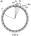
- Fig. 6 is a diagram illustrating an arrangement of a plurality of magnets 343 of the rotor magnet 341.
- the rotor magnet 341 includes the plurality of magnets 343.
- the plurality of magnets 343 are disposed at substantially equal angular intervals in the peripheral direction around the center axis J1.
- the number of poles which is the number of the plurality of magnets 343, is 24. Therefore, a ratio of the number of slots to the number of poles is 3:4.
- an angle ⁇ 3 in the peripheral direction between center positions of two adjacent magnets 343 in the peripheral direction is 15 degrees.
- the center position of the magnet 343 is a position of a center of the magnet 343 in the peripheral direction in a plan view.
- the angle ⁇ 3 is referred to as an "inter-magnet angle ⁇ 3.”
- an angle ⁇ 4 of one magnet 343 in the peripheral direction is referred to as a "magnet angle ⁇ 4.”
- the magnet angle ⁇ 4 is an angle between a straight line passing through the center axis J1 and contacting one peripheral end portion of the magnet 343, and a straight line passing through the center axis J1 and contacting the other peripheral end portion of the magnet 343, in a plan view.
- a ratio of the inter-magnet angle ⁇ 3 and the magnet angle ⁇ 4 is referred to as a "magnet width ratio.”
- a ratio of the slot open ratio to the magnet width ratio is 0.6 to 0.7.
- the magnet width ratio is 0.75 to 0.90.
- the rotating portion 3 (that is, the shaft 31 and the rotor 32) rotates around the center axis J1.
- the rotating portion 3 is rotatable in both a clockwise direction and a counterclockwise direction in a plan view.
- Fig. 7 is a cross-sectional view illustrating the axial flow fan 10 using the motor 1 described above.
- the axial flow fan 10 includes the motor 1 and an impeller 11.
- the impeller 11 is attached to an upper end portion of the shaft 31 above the rotor 32.
- the impeller 11, for example, sends wind downward from an upper side of the rotor 32.
- Fig. 8 is a diagram illustrating, when the slot open ratio of the stator core 220 and the magnet width ratio of the rotor magnet 341 are variously tailored, the magnet width ratio in which a cogging torque is minimized for the respective slot open ratio, which is obtained by the simulation with the motor 1 having 18 slots and 24 poles. Additionally, Fig. 8 also illustrates a ratio of the slot open ratio to the magnet width ratio in which the cogging torque is minimized.
- Examples 1 to 5 illustrated in Fig. 8 show results of the simulations in a case where the slot open ratio is 0.6, 0.575, 0.55, 0.525 and 0.5, respectively.
- Comparative Examples 1 and 2 show results of the simulations in a case where the slot open ratio is 0.45 and 0.4, respectively.
- the motor 1 may have different numbers of slots and poles as long as the ratio of the number of slot to the number of poles is 3:4.
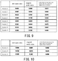
- Fig. 9 is a diagram illustrating, when the slot open ratio of the stator core 220 and the magnet width ratio of the rotor magnet 341 are variously tailored, the magnet width ratio in which a cogging torque is minimized for the respective slot open ratio, which is obtained by the simulation with the motor 1 having 12 or 24 slots. Additionally, Fig. 9 also illustrates a ratio of the slot open ratio to the magnet width ratio in which the cogging torque is minimized.
- Examples 6 to 9 illustrated in Fig. 9 show results of the simulations in a case where the number of slots is 12 while the slot open ratio is 0.6, 0.567, 0.533, and 0.5, respectively.
- Examples 10 to 13 show results of the simulations in a case where the number of slots is 24 while the slot open ratio is 0.6, 0.567, 0.533, and 0.5, respectively.
- the slot open ratio is 0.5 or more, and the ratio of the slot open ratio to the magnet width ratio is 0.6 to 0.7, as in Examples 1 to 5. Therefore, the output torque of the motor 1 can be increased while decreasing the cogging torque. Moreover, in Examples 6 to 13, the magnet width ratio is 0.75 to 0.90.
- the stator core 220 includes the annular core back portion 221 and the plurality of teeth 222.
- the plurality of teeth 222 extend radially from the core back portion 221 to the rotor magnet 341 having the plurality of magnets 343.
- the ratio of the number of slots to the number of poles is 3:4.
- the number of slots is the number of the plurality of teeth 222, and the number of poles is the number of magnets 343 of the rotor magnet 341.
- the slot open ratio is a ratio of the slot open angle ⁇ 2 between the two adjacent teeth 222 in the peripheral direction to the angle ⁇ 1 between center lines of the two teeth 222, which is 0.5 or more.
- the ratio of the peripheral angle ⁇ 4 of one magnet 343 to the angle ⁇ 3 between center positions of two adjacent magnets 243 in the peripheral direction is set as the magnet ratio
- the ratio of the slot open ratio to the magnet ratio is 0.6 to 0.7. Therefore, as described above, the output torque of the motor 1 can be increased while decreasing the cogging torque.
- the magnet width ratio is 0.75 to the 0.90. Consequently, the cogging torque can be further decreased.
- the motor 1 includes the armature 22 including the stator core 220, the rotor 32 including the rotor magnet 341, and the bearing mechanism 4 rotatably supporting the rotor 32.
- the rotor magnet 341 is disposed radially outward of the plurality of teeth 222 of the armature 22.
- the number of slots in the motor 1 is, for example, 12, 18 or 24. Therefore, it is possible to provide the external rotor motor 1 with the increased output torque and the reduced cogging torque.
- the motor 1 is an external rotor motor, but the simulation was also carried out for an internal rotor motor.
- Examples 14 to 16 illustrated in Fig. 10 show results of the simulations for the internal rotor motor in a case where the number of slots is 18 while the slot open ratio is 0.6, 0.55, and 0.5, respectively. Additionally, Fig. 10 also illustrates a ratio of the slot open ratio to the magnet width ratio in which the cogging torque is minimized.
- the ratio of the number of slots to the number of poles is 3:4, the slot open ratio is 0.5 or more, and the ratio of the slot open ratio to the magnet width ratio is 0.6 to 0.7, similar to other examples. Therefore, the output torque of the motor can be increased while decreasing the cogging torque. Moreover, the magnet width ratio is 0.75 to 0.90, thus the cogging torque can be further decreased.
- the internal rotor motor includes an armature including a stator core, a rotor including a rotor magnet, and a bearing mechanism rotatably supporting the rotor.
- the rotor magnet is disposed radially inward of a plurality of teeth of the armature.
- the number of slots in the internal rotor motor is, for example, 18. Therefore, it is possible to provide the internal rotor motor with the increased output torque and the reduced cogging torque.
- stator core 220, the external rotor motor 1 and the internal rotor motor can be modified in various ways.
- the magnet width ratio may be less than 0.75, or alternatively may exceed 0.90.
- the number of slots is not limited to 12, 18 or 24. The numbers of slots and poles may be appropriately altered.
- the shape and structure of the external rotor motor 1 can be appropriately altered from the examples described above, and it is the same for the internal rotor motor.
- the stator core according to the present invention can be used for a motor with various structures and for various purposes. Furthermore, the motor according to the prevent invention can be used as a motor for various purposes. Reference Signs List
Landscapes
- Engineering & Computer Science (AREA)
- Power Engineering (AREA)
- Iron Core Of Rotating Electric Machines (AREA)
- Permanent Field Magnets Of Synchronous Machinery (AREA)
- Permanent Magnet Type Synchronous Machine (AREA)
Abstract
Description
- The present invention relates to a stator core, and a motor including the stator core.
- Conventionally, a technique for reducing cogging torque has been proposed for a brushless motor. For example, in a
brushless motor 1 disclosed in Japanese Unexamined Patent Application Publication No.2014-230444 protrusion portion 12 is provided at a center of apole tooth portion 9 of eachsalient pole 8 of astator core 6, and a pair ofnotch portions 13 is provided on both sides of theprotrusion portion 12. Accordingly, the cogging torque of thebrushless motor 1 is reduced. - PTL 1: Japanese Unexamined Patent Application Publication No.
2014-230444 - However, in an engine cooling fan or the like, a motor having a large number of poles and slots is used for increasing an output torque of the motor. Even in such a multi-pole and multi-slot motor, it is required to reduce a cogging torque while suppressing reduction in the output torque of the motor.
- The present invention is made to reduce a cogging torque with consideration of the challenges stated above. Solution to Problem
- An exemplified stator core according to one embodiment of the present invention includes an annular core back portion; and a plurality of teeth extending radially from the core back portion to a rotor magnet having a plurality of magnets. A ratio of the number of slots which is the number of the plurality of teeth to the number of poles which is the number of the plurality of magnets of the rotor magnet is 3:4. A slot open ratio which is a ratio of a slot open angle between two adjacent teeth in a peripheral direction to an angle between center lines of the two teeth is 0.5 or more. When, in the rotor magnet, a ratio of a peripheral angle of one magnet to an angle between center positions of two adjacent magnets in the peripheral direction is set as a magnet ratio, a ratio of the slot open ratio to the magnet ratio is 0.6 to 0.7.
- According to the present invention, it is possible to reduce a cogging torque.
-
- [
Fig. 1] Fig. 1 is a perspective view of a motor according to one embodiment. - [
Fig. 2] Fig. 2 is a perspective view of the motor. - [
Fig. 3] Fig. 3 is a longitudinal cross-sectional view of the motor. - [
Fig. 4] Fig. 4 is a plan view of a stator core. - [
Fig. 5] Fig. 5 is a longitudinal cross-sectional view of a shaft and a rotor. - [
Fig. 6] Fig. 6 is a diagram illustrating an arrangement of a plurality of magnets. - [
Fig. 7] Fig. 7 is a longitudinal cross-sectional view of an axial flow fan. - [
Fig. 8] Fig. 8 is a diagram illustrating a slot open ratio and a magnet width ratio at which a cogging torque is minimized. - [
Fig. 9] Fig. 9 is a diagram illustrating a slot open ratio and a magnet width ratio at which a cogging torque is minimized. - [
Fig. 10] Fig. 10 is a diagram illustrating a slot open ratio and a magnet width ratio at which a cogging torque is minimized. -
Fig. 1 is a perspective view showing an appearance of amotor 1 according to one exemplary embodiment of the present invention. Themotor 1 is an external rotor brushless motor. Themotor 1 is used to, for example, rotate an impeller in an axial flow fan.Fig. 2 is a perspective view of themotor 1 as viewed from a direction different from that ofFig. 1 .Fig. 3 is a longitudinal cross-sectional view of themotor 1. Parallel slanting lines in the detailed cross-section are omitted inFig. 3 . Moreover, a configuration on a far side from the cross-section and a partial outer surface of the motor are also drawn inFig. 3 . - In this specification, an upper side and a lower side in a direction of a center axis J1 of the
motor 1 inFig. 3 are simply referred to as an "upper side" and a "lower side", respectively. The upper and lower sides in this specification do not indicate upper and lower sides in a gravity direction when installed into the actual equipment. Hereinafter, a peripheral direction around the center axis J1 is simply referred to as a "peripheral direction", and a radial direction around the center axis J1 is simply referred to as a "radial direction." Moreover, a direction parallel to the center axis J1 is referred to as a "vertical direction" or an "axial direction." - The
motor 1 includes astationary portion 2, a rotatingportion 3, and abearing mechanism 4. Thebearing mechanism 4 rotatably supports the rotatingportion 3 with respect to thestationary portion 2. Thestationary portion 2 includes abracket 21, anarmature 22, and abus bar unit 26. The rotatingportion 3 includes ashaft 31 and arotor 32. Thebearing mechanism 4 includes a lower ball bearing 41 and an upper ball bearing 42. - The
bracket 21 includes thecylindrical portion 212. Thecylindrical portion 212 is a substantially cylindrical portion centered on the center axis J1 oriented in the vertical direction. Thebearing mechanism 4 is fixed to an inner peripheral surface of thecylindrical portion 212 of thebracket 21. In particular, the lower ball bearing 41 of thebearing mechanism 4 is fixed to an inner peripheral surface of a lower portion of thecylindrical portion 212. Moreover, the upper ball bearing 42 is fixed to an inner peripheral surface of an upper portion of thecylindrical portion 212. - The
armature 22 is fixed to an outer peripheral surface of thecylindrical portion 212 of thebracket 21. Thearmature 22 is disposed radially outward of thebearing mechanism 4. Thearmature 22 is electrically connected to thebus bar unit 26. Thearmature 22 is electrically connected to an external power supply (not shown) via thebus bar unit 26. - The
armature 22 includes astator core 220, aninsulator 223, and a plurality ofcoils 224. Thestator core 220 includes acore back portion 221 and a plurality ofteeth 222. Theinsulator 223 is an insulator covering surfaces of the plurality ofteeth 222. The plurality ofcoils 224 are formed by winding a conductive wire from above theinsulator 223 to the plurality ofteeth 222. In this embodiment, the plurality ofcoil 224 are three-phase coils. -
Fig. 4 is a plan view of thestator core 220. Thecore back portion 221 is an annular portion centered on the center axis J1. Thecore back portion 221 is fixed to the outer peripheral surface of thecylindrical portion 212 of thebracket 21. The plurality ofteeth 222 eradiate radially outward from thecore back portion 221. The plurality ofteeth 222 are arranged at substantially equal angular intervals in the peripheral direction. Eachtooth 222 includes atooth body portion 226 and atooth tip portion 227. Thetooth body portion 226 extends substantially linearly and radially outward from the core backportion 221. Thetooth tip portion 227 extends to both peripheral sides from a radial outer end portion of thetooth body portion 226. The core backportion 221 and the plurality ofteeth 222 are, for example, a single member made of metal. - In the example illustrated in
Fig. 4 , the number of slots, which is the number of the plurality ofteeth 222, is 18. An angle θ1 in the peripheral direction between center lines of twoadjacent teeth 222 in the peripheral direction is 20 degrees. The center line of thetooth 222 is a straight line passing through the center axis J1 and a center in the peripheral direction of thetooth 222 in a plan view. Hereinafter, the angle θ1 is referred to as an "inter-teeth angle θ1." Furthermore, the angle θ2 in the peripheral direction of a slot open between the twoadjacent teeth 222 in the peripheral direction is simply referred to as a "slot open angle θ2." The slot open is a space between tip portions of the twoadjacent teeth 222 in the peripheral direction. In the example illustrated inFig. 4 , the slot open angle θ2 is an angle between a straight line passing through the center axis J1 and contacting a peripheral end portion of thetooth tip portion 227 of onetooth 222, and a straight line passing through the center axis J1 and contacting a peripheral end portion of thetooth tip portion 227 of theother tooth 222, in a plan view. - Hereinafter, a ratio of the slot open angle θ2 to the inter-teeth angle θ1 is referred to as a "slot open ratio." In the
stator core 220 of themotor 1, the slot open ratio is 0.5 or more. - The
shaft 31 exemplified inFig. 3 is a substantially columnar or cylindrical member, which is centered on the center axis J1. Theshaft 31 is made of, for example, metal. Theshaft 31 is formed by, for example, an aluminum alloy. As shown inFig. 3 , theshaft 31 is rotatably supported together with therotor 32 by thebearing mechanism 4. In particular, thelower ball bearing 41 of thebearing mechanism 4 supports a lower portion of theshaft 31. Theupper ball bearing 42 is disposed higher than thelower ball bearing 41 and supports theshaft 31. The impeller of the axial flow fan, for example, is attached to an upper end portion of theshaft 31. -
Fig. 5 shows longitudinal cross-sectional views of theshaft 31 and therotor 32. Therotor 32 is connected to theshaft 31. Therotor 32 is a substantially cylindrical covered member centered on the center axis J1. Therotor 32 opens downward. Therotor 32 includes arotor lid portion 321, a rotorside wall portion 322, arotor magnet 341, and arotor yoke 342. - The
rotor lid portion 321 is connected to theshaft 31. Therotor lid portion 321 is a substantially disk-like portion centered on the center axis J1. The rotorside wall portion 322 extends downward from an outer edge portion of therotor lid portion 321. The rotorside wall portion 322 is a substantially cylindrical portion centered on the center axis J1. In the example illustrated inFig. 5 , therotor lid portion 321 and the rotorside wall portion 322 are a single member made of resin. Moreover, therotor lid portion 321 and the rotorside wall portion 322 are integrally formed with theshaft 31 by the insert molding. - The
rotor magnet 341 is fixed to an inner peripheral surface of the rotorside wall portion 322. Therotor magnet 341 includes a plurality ofmagnets 343 arranged in the peripheral direction. Therotor magnet 341 is radially opposed to thearmature 22 radially outward of thearmature 22. In the example illustrated inFig. 5 , therotor yoke 342 is disposed between amagnet 343 of therotor magnet 341 and the rotorside wall portion 322. In other words, therotor magnet 341 is indirectly fixed to the inner peripheral surface of the rotorside wall portion 322 via therotor yoke 342. Therotor yoke 342 is made of metal. Alternatively, therotor yoke 342 may be excluded and therotor magnet 341 may be directly fixed to the inner peripheral surface of the rotorside wall portion 322, in themotor 1. -
Fig. 6 is a diagram illustrating an arrangement of a plurality ofmagnets 343 of therotor magnet 341. Therotor magnet 341 includes the plurality ofmagnets 343. The plurality ofmagnets 343 are disposed at substantially equal angular intervals in the peripheral direction around the center axis J1. In the example illustrated inFig. 6 , the number of poles, which is the number of the plurality ofmagnets 343, is 24. Therefore, a ratio of the number of slots to the number of poles is 3:4. In therotor magnet 341, an angle θ3 in the peripheral direction between center positions of twoadjacent magnets 343 in the peripheral direction is 15 degrees. The center position of themagnet 343 is a position of a center of themagnet 343 in the peripheral direction in a plan view. Hereinafter, the angle θ3 is referred to as an "inter-magnet angle θ3." Moreover, an angle θ4 of onemagnet 343 in the peripheral direction is referred to as a "magnet angle θ4." The magnet angle θ4 is an angle between a straight line passing through the center axis J1 and contacting one peripheral end portion of themagnet 343, and a straight line passing through the center axis J1 and contacting the other peripheral end portion of themagnet 343, in a plan view. - Hereinafter, a ratio of the inter-magnet angle θ3 and the magnet angle θ4 is referred to as a "magnet width ratio." In the
magnet 341 of themotor 1, a ratio of the slot open ratio to the magnet width ratio is 0.6 to 0.7. In themotor 1, it is preferable the magnet width ratio is 0.75 to 0.90. - In the
motor 1, a current is supplied to thecoil 224 via thebus bar unit 26, whereby a torque is generated between thecoil 224 and therotor magnet 341. Therefore, the rotating portion 3 (that is, theshaft 31 and the rotor 32) rotates around the center axis J1. The rotatingportion 3 is rotatable in both a clockwise direction and a counterclockwise direction in a plan view. -
Fig. 7 is a cross-sectional view illustrating theaxial flow fan 10 using themotor 1 described above. Theaxial flow fan 10 includes themotor 1 and animpeller 11. Theimpeller 11 is attached to an upper end portion of theshaft 31 above therotor 32. Theimpeller 11, for example, sends wind downward from an upper side of therotor 32. -
Fig. 8 is a diagram illustrating, when the slot open ratio of thestator core 220 and the magnet width ratio of therotor magnet 341 are variously tailored, the magnet width ratio in which a cogging torque is minimized for the respective slot open ratio, which is obtained by the simulation with themotor 1 having 18 slots and 24 poles. Additionally,Fig. 8 also illustrates a ratio of the slot open ratio to the magnet width ratio in which the cogging torque is minimized. - Examples 1 to 5 illustrated in
Fig. 8 show results of the simulations in a case where the slot open ratio is 0.6, 0.575, 0.55, 0.525 and 0.5, respectively. Comparative Examples 1 and 2 show results of the simulations in a case where the slot open ratio is 0.45 and 0.4, respectively. - In Comparative Examples 1 and 2, a size of a winding wound around the
teeth 222 is limited since the slot open ratio is relatively small. Meanwhile, in Examples 1 to 5, the slot open is relatively large since the slot open ratio is 0.5 or more, thus the winding can be quite largely around theteeth 222. Consequently, it is possible to increase an output torque of themotor 1. Moreover, the ratio of the slot open ratio to the magnet width ratio is 0.6 to 0.7 as shown inFig. 8 , thus another advantageous effect of decreasing the cogging torque can also be obtained. In Examples 1 to 5, the magnet width ratio is 0.75 to 0.90. - The
motor 1 may have different numbers of slots and poles as long as the ratio of the number of slot to the number of poles is 3:4.Fig. 9 is a diagram illustrating, when the slot open ratio of thestator core 220 and the magnet width ratio of therotor magnet 341 are variously tailored, the magnet width ratio in which a cogging torque is minimized for the respective slot open ratio, which is obtained by the simulation with themotor 1 having 12 or 24 slots. Additionally,Fig. 9 also illustrates a ratio of the slot open ratio to the magnet width ratio in which the cogging torque is minimized. - Examples 6 to 9 illustrated in
Fig. 9 show results of the simulations in a case where the number of slots is 12 while the slot open ratio is 0.6, 0.567, 0.533, and 0.5, respectively. Examples 10 to 13 show results of the simulations in a case where the number of slots is 24 while the slot open ratio is 0.6, 0.567, 0.533, and 0.5, respectively. - In Examples 6 to 13, the slot open ratio is 0.5 or more, and the ratio of the slot open ratio to the magnet width ratio is 0.6 to 0.7, as in Examples 1 to 5. Therefore, the output torque of the
motor 1 can be increased while decreasing the cogging torque. Moreover, in Examples 6 to 13, the magnet width ratio is 0.75 to 0.90. - As described above, the
stator core 220 includes the annular core backportion 221 and the plurality ofteeth 222. The plurality ofteeth 222 extend radially from the core backportion 221 to therotor magnet 341 having the plurality ofmagnets 343. The ratio of the number of slots to the number of poles is 3:4. The number of slots is the number of the plurality ofteeth 222, and the number of poles is the number ofmagnets 343 of therotor magnet 341. In thestator core 220, the slot open ratio is a ratio of the slot open angle θ2 between the twoadjacent teeth 222 in the peripheral direction to the angle θ1 between center lines of the twoteeth 222, which is 0.5 or more. Moreover, in therotor magnet 341, when the ratio of the peripheral angle θ4 of onemagnet 343 to the angle θ3 between center positions of two adjacent magnets 243 in the peripheral direction is set as the magnet ratio, the ratio of the slot open ratio to the magnet ratio is 0.6 to 0.7. Therefore, as described above, the output torque of themotor 1 can be increased while decreasing the cogging torque. - In the
stator core 220, the magnet width ratio is 0.75 to the 0.90. Consequently, the cogging torque can be further decreased. - The
motor 1 includes thearmature 22 including thestator core 220, therotor 32 including therotor magnet 341, and thebearing mechanism 4 rotatably supporting therotor 32. Therotor magnet 341 is disposed radially outward of the plurality ofteeth 222 of thearmature 22. The number of slots in themotor 1 is, for example, 12, 18 or 24. Therefore, it is possible to provide theexternal rotor motor 1 with the increased output torque and the reduced cogging torque. - In the example as described above, the
motor 1 is an external rotor motor, but the simulation was also carried out for an internal rotor motor. Examples 14 to 16 illustrated inFig. 10 show results of the simulations for the internal rotor motor in a case where the number of slots is 18 while the slot open ratio is 0.6, 0.55, and 0.5, respectively. Additionally,Fig. 10 also illustrates a ratio of the slot open ratio to the magnet width ratio in which the cogging torque is minimized. - In the internal rotor motor, the ratio of the number of slots to the number of poles is 3:4, the slot open ratio is 0.5 or more, and the ratio of the slot open ratio to the magnet width ratio is 0.6 to 0.7, similar to other examples. Therefore, the output torque of the motor can be increased while decreasing the cogging torque. Moreover, the magnet width ratio is 0.75 to 0.90, thus the cogging torque can be further decreased.
- The internal rotor motor includes an armature including a stator core, a rotor including a rotor magnet, and a bearing mechanism rotatably supporting the rotor. The rotor magnet is disposed radially inward of a plurality of teeth of the armature. The number of slots in the internal rotor motor is, for example, 18. Therefore, it is possible to provide the internal rotor motor with the increased output torque and the reduced cogging torque.
- The
stator core 220, theexternal rotor motor 1 and the internal rotor motor can be modified in various ways. - In the
stator core 220, the magnet width ratio may be less than 0.75, or alternatively may exceed 0.90. Furthermore, in thestator core 220, the number of slots is not limited to 12, 18 or 24. The numbers of slots and poles may be appropriately altered. - The shape and structure of the
external rotor motor 1 can be appropriately altered from the examples described above, and it is the same for the internal rotor motor. - The configurations in the embodiment stated above and the modifications may be appropriately combined as long as they do not conflict to each other.
- The stator core according to the present invention can be used for a motor with various structures and for various purposes. Furthermore, the motor according to the prevent invention can be used as a motor for various purposes. Reference Signs List
-
- 1
- motor
- 4
- bearing mechanism
- 22
- armature
- 32
- rotor
- 220
- stator core
- 221
- core back portion
- 222
- teeth
- 341
- rotor magnet
- 343
- magnet
- J1
- center axis
- θ1
- inter-teeth angle
- θ2
- slot open angle
- θ3
- inter-magnet angle
- θ4
- magnet angle
Claims (4)
- A stator core comprising:an annular core back portion; anda plurality of teeth extending radially from the core back portion to a rotor magnet having a plurality of magnets,wherein a ratio of the number of slots which is the number of the plurality of teeth to the number of poles which is the number of the plurality of magnets of the rotor magnet is 3:4,a slot open ratio which is a ratio of a slot open angle between two adjacent teeth in a peripheral direction to an angle between center lines of the two teeth is 0.5 or more, andwhen, in the rotor magnet, a ratio of a peripheral angle of one magnet to an angle between center positions of two adjacent magnets in the peripheral direction is set as a magnet ratio, a ratio of the slot open ratio to the magnet ratio is 0.6 to 0.7.
- The stator core according to Claim 1,
wherein the magnet width ratio is 0.75 to 0.90. - A motor comprising:an armature having the stator core according to Claim 1 or 2;a rotor having the rotor magnet; anda bearing mechanism rotatably supporting the rotor,wherein the rotor magnet is disposed radially outward of the plurality of teeth, andthe number of slots is 12, 18 or 24.
- A motor comprising:an armature having the stator core according to Claim 1 or 2;a rotor having the rotor magnet; anda bearing mechanism rotatably supporting the rotor,wherein the rotor magnet is disposed radially inward of the plurality of teeth, andthe number of slots is 18.
Applications Claiming Priority (3)
| Application Number | Priority Date | Filing Date | Title |
|---|---|---|---|
| US201662371342P | 2016-08-05 | 2016-08-05 | |
| JP2017041574 | 2017-03-06 | ||
| PCT/JP2017/028373 WO2018025988A1 (en) | 2016-08-05 | 2017-08-04 | Stator core and motor |
Publications (2)
| Publication Number | Publication Date |
|---|---|
| EP3496247A1 true EP3496247A1 (en) | 2019-06-12 |
| EP3496247A4 EP3496247A4 (en) | 2020-04-08 |
Family
ID=65864348
Family Applications (1)
| Application Number | Title | Priority Date | Filing Date |
|---|---|---|---|
| EP17837089.6A Withdrawn EP3496247A4 (en) | 2016-08-05 | 2017-08-04 | Stator core and motor |
Country Status (4)
| Country | Link |
|---|---|
| US (1) | US20190173366A1 (en) |
| EP (1) | EP3496247A4 (en) |
| JP (1) | JPWO2018025988A1 (en) |
| CN (1) | CN109565231A (en) |
Families Citing this family (1)
| Publication number | Priority date | Publication date | Assignee | Title |
|---|---|---|---|---|
| TWI723493B (en) | 2019-08-14 | 2021-04-01 | 財團法人工業技術研究院 | Combined motor stator |
Family Cites Families (11)
| Publication number | Priority date | Publication date | Assignee | Title |
|---|---|---|---|---|
| DE4310226A1 (en) * | 1993-03-31 | 1994-10-06 | Philips Patentverwaltung | Electric motor excited by permanent magnets |
| JPH08322167A (en) * | 1995-05-26 | 1996-12-03 | Matsushita Electric Ind Co Ltd | Motor with core |
| JPH09182325A (en) * | 1995-12-22 | 1997-07-11 | Toshiba Corp | Permanent magnet type motor |
| JP3804343B2 (en) * | 1999-06-29 | 2006-08-02 | 松下電器産業株式会社 | Motor core and motor using the same |
| JP3995450B2 (en) * | 2000-12-20 | 2007-10-24 | ヤマハモーターエレクトロニクス株式会社 | Permanent magnet type rotating electric machine |
| WO2005091467A1 (en) * | 2004-03-19 | 2005-09-29 | Matsushita Electric Industrial Co., Ltd. | Brushless motor |
| TWI343689B (en) * | 2006-12-28 | 2011-06-11 | Delta Electronics Inc | Permanent magnet rotary structure of electric machinery |
| JP5221219B2 (en) * | 2008-06-20 | 2013-06-26 | 株式会社日立産機システム | Permanent magnet synchronous motor |
| JP2010246197A (en) * | 2009-04-02 | 2010-10-28 | Mabuchi Motor Co Ltd | Magnetic pole core and dc motor using the same |
| JP6095267B2 (en) * | 2012-02-24 | 2017-03-15 | 株式会社クリーンクラフト | Three-phase permanent magnet synchronous motor |
| CN103427510B (en) * | 2012-05-17 | 2016-01-06 | 深圳市配天电机技术有限公司 | A kind of concentratred winding motor, generator and motor |
-
2017
- 2017-08-04 EP EP17837089.6A patent/EP3496247A4/en not_active Withdrawn
- 2017-08-04 JP JP2018532000A patent/JPWO2018025988A1/en active Pending
- 2017-08-04 US US16/321,516 patent/US20190173366A1/en not_active Abandoned
- 2017-08-04 CN CN201780049040.7A patent/CN109565231A/en active Pending
Also Published As
| Publication number | Publication date |
|---|---|
| EP3496247A4 (en) | 2020-04-08 |
| CN109565231A (en) | 2019-04-02 |
| US20190173366A1 (en) | 2019-06-06 |
| JPWO2018025988A1 (en) | 2019-06-06 |
Similar Documents
| Publication | Publication Date | Title |
|---|---|---|
| US8890387B2 (en) | Stator and motor | |
| JP7021472B2 (en) | motor | |
| US10153673B2 (en) | Production method for rotating electrical machine | |
| US20150022044A1 (en) | System and method for reducing torque ripple in an interior permanent magnet motor | |
| CN105474512A (en) | Synchronous electric motor | |
| US10340758B2 (en) | Permanent magnet motor | |
| JP2012147615A (en) | Motor and low-speed rotation structure of blower fan | |
| JP2000295805A (en) | Permanent magnet rotating electric machine | |
| JP2012210105A (en) | Three-phase brushless motor | |
| US20130320798A1 (en) | System and method for reducing cogging torque in an interior permanent magnet motor | |
| JP2010161832A (en) | Permanent magnet rotating electrical machine | |
| US20210135518A1 (en) | Rotor and motor | |
| US20190173366A1 (en) | Stator core and motor | |
| US10361613B2 (en) | Single phase motor and rotor, having plurality of permanent magnets, of the same | |
| TW201926856A (en) | Slotless electric motor, and electric blower or electric vacuum cleaner using same including a hollow cylindrical core, a stator, a permanent magnet rotor and a frame body | |
| KR20190074467A (en) | A Motor having split stator | |
| WO2018025988A1 (en) | Stator core and motor | |
| CN109842258B (en) | Brushless motor and blower | |
| JP2009033925A (en) | Synchronous reluctance motor | |
| JP2014192997A (en) | Electric motor | |
| JP2019162005A (en) | Brushless motor, and blower | |
| JP6226794B2 (en) | Squirrel-cage induction motor | |
| KR100672538B1 (en) | Fastening structure of bracket and housing of motor | |
| JP2019062649A (en) | Stator and motor | |
| JP2013135548A (en) | Brushless motor |
Legal Events
| Date | Code | Title | Description |
|---|---|---|---|
| PUAI | Public reference made under article 153(3) epc to a published international application that has entered the european phase |
Free format text: ORIGINAL CODE: 0009012 |
|
| STAA | Information on the status of an ep patent application or granted ep patent |
Free format text: STATUS: REQUEST FOR EXAMINATION WAS MADE |
|
| 17P | Request for examination filed |
Effective date: 20190304 |
|
| AK | Designated contracting states |
Kind code of ref document: A1 Designated state(s): AL AT BE BG CH CY CZ DE DK EE ES FI FR GB GR HR HU IE IS IT LI LT LU LV MC MK MT NL NO PL PT RO RS SE SI SK SM TR |
|
| AX | Request for extension of the european patent |
Extension state: BA ME |
|
| DAV | Request for validation of the european patent (deleted) | ||
| DAX | Request for extension of the european patent (deleted) | ||
| A4 | Supplementary search report drawn up and despatched |
Effective date: 20200309 |
|
| RIC1 | Information provided on ipc code assigned before grant |
Ipc: H02K 1/27 20060101ALI20200303BHEP Ipc: H02K 1/14 20060101ALI20200303BHEP Ipc: H02K 21/22 20060101AFI20200303BHEP Ipc: H02K 7/14 20060101ALI20200303BHEP Ipc: H02K 21/16 20060101ALI20200303BHEP Ipc: H02K 29/03 20060101ALI20200303BHEP |
|
| STAA | Information on the status of an ep patent application or granted ep patent |
Free format text: STATUS: THE APPLICATION IS DEEMED TO BE WITHDRAWN |
|
| 18D | Application deemed to be withdrawn |
Effective date: 20201006 |