EP3496236A1 - Rotor of an electric machine - Google Patents
Rotor of an electric machine Download PDFInfo
- Publication number
- EP3496236A1 EP3496236A1 EP18205715.8A EP18205715A EP3496236A1 EP 3496236 A1 EP3496236 A1 EP 3496236A1 EP 18205715 A EP18205715 A EP 18205715A EP 3496236 A1 EP3496236 A1 EP 3496236A1
- Authority
- EP
- European Patent Office
- Prior art keywords
- rotor
- magnets
- shaft
- region
- respect
- Prior art date
- Legal status (The legal status is an assumption and is not a legal conclusion. Google has not performed a legal analysis and makes no representation as to the accuracy of the status listed.)
- Withdrawn
Links
Images


Classifications
-
- H—ELECTRICITY
- H02—GENERATION; CONVERSION OR DISTRIBUTION OF ELECTRIC POWER
- H02K—DYNAMO-ELECTRIC MACHINES
- H02K1/00—Details of the magnetic circuit
- H02K1/06—Details of the magnetic circuit characterised by the shape, form or construction
- H02K1/22—Rotating parts of the magnetic circuit
- H02K1/27—Rotor cores with permanent magnets
- H02K1/2706—Inner rotors
- H02K1/272—Inner rotors the magnetisation axis of the magnets being perpendicular to the rotor axis
- H02K1/274—Inner rotors the magnetisation axis of the magnets being perpendicular to the rotor axis the rotor consisting of two or more circumferentially positioned magnets
- H02K1/2753—Inner rotors the magnetisation axis of the magnets being perpendicular to the rotor axis the rotor consisting of two or more circumferentially positioned magnets the rotor consisting of magnets or groups of magnets arranged with alternating polarity
- H02K1/276—Magnets embedded in the magnetic core, e.g. interior permanent magnets [IPM]
- H02K1/2766—Magnets embedded in the magnetic core, e.g. interior permanent magnets [IPM] having a flux concentration effect
- H02K1/2773—Magnets embedded in the magnetic core, e.g. interior permanent magnets [IPM] having a flux concentration effect consisting of tangentially magnetized radial magnets
-
- H—ELECTRICITY
- H02—GENERATION; CONVERSION OR DISTRIBUTION OF ELECTRIC POWER
- H02K—DYNAMO-ELECTRIC MACHINES
- H02K1/00—Details of the magnetic circuit
- H02K1/06—Details of the magnetic circuit characterised by the shape, form or construction
- H02K1/22—Rotating parts of the magnetic circuit
- H02K1/28—Means for mounting or fastening rotating magnetic parts on to, or to, the rotor structures
- H02K1/30—Means for mounting or fastening rotating magnetic parts on to, or to, the rotor structures using intermediate parts, e.g. spiders
-
- H—ELECTRICITY
- H02—GENERATION; CONVERSION OR DISTRIBUTION OF ELECTRIC POWER
- H02K—DYNAMO-ELECTRIC MACHINES
- H02K2213/00—Specific aspects, not otherwise provided for and not covered by codes H02K2201/00 - H02K2211/00
- H02K2213/03—Machines characterised by numerical values, ranges, mathematical expressions or similar information
Definitions
- the electric machine is for example a component of an industrial plant, such as a servo press. In other words, in particular a press is driven by means of the electric machine.
- the electric machine is preferably used in plastics processing and / or plastic manufacturing.
- an extruder or other component of a plastic injection molding machine, such as a stamp is driven by the electric machine.
- the electric machine is a component of a marine propulsion, which is in particular provided and arranged to be mounted within a nacelle on a hull of a ship.
- the electric machine is part of a bicycle, such as a pedelec, and serves to propel the bicycle.
- the support elements 60 are made of a para or diamagnetic material, in particular of a plastic material.
- the support elements 60 By means of the support elements 60 in this case is a bending of the first Areas 42 due to the comparatively delicate connection to the shaft 26 avoided by means of the second regions 50, so that the stability of the rotor 28 is increased.
- the support elements 60 are made of the para or diamagnetic material, in this case the magnetic fields provided by the magnets 36 spread comparatively small in them, so that a magnetic short circuit can take place only by means of the second regions 50 and the shaft 26. Consequently, most of the magnetic field lines of the magnets 36 are forced into the air gap 34 and thus to the stator 10, which increases efficiency.
Abstract
Die Erfindung betrifft einen Rotor (28) einer elektrischen Maschine, mit einer Welle (26) und einem die Welle (26) zumindest abschnittsweise umgebenden Abschnitt (30). Der Abschnitt (30) weist eine Anzahl an zueinander beabstandeten und in einer axialen Richtung angeordneten Magneten (36) und eine Anzahl an zueinander beabstandeten und in der axialen Richtung angeordneten Polschuhen (44) auf. Jeder Polschuh (44) umfasst einen in einer radialen Richtung (38) außenliegenden ersten Bereich (42), der zwischen in einer tangentialen Richtung (40) benachbarten Magneten (36) angeordnet und symmetrisch bezüglich einer zugeordneten ersten radialen Geraden (48) ist, und einen in der radialen Richtung (38) innenliegenden zweiten Bereich (50), der asymmetrisch bezüglich der jeweils zugeordneten ersten radialen Geraden (48) ist, und der an der Welle (26) angebunden ist. Die Erfindung betrifft ferner eine elektrische Maschine.The invention relates to a rotor (28) of an electrical machine, having a shaft (26) and a section (30) surrounding the shaft (26) at least in sections. The section (30) has a number of magnets (36) spaced apart and arranged in an axial direction and a number of pole pieces (44) spaced apart and arranged in the axial direction. Each pole piece (44) comprises a first region (42) which is external in a radial direction (38) and which is arranged between magnets (36) adjacent in a tangential direction (40) and is symmetrical with respect to an associated first radial straight line (48), and a second region (50) lying inside in the radial direction (38), which is asymmetrical with respect to the respectively assigned first radial straight line (48) and which is connected to the shaft (26). The invention further relates to an electrical machine.
Description
Die Erfindung betrifft einen Rotor einer elektrischen Maschine, mit einer Welle und einem die Welle zumindest abschnittsweise umgebenden Abschnitt. Die elektrische Maschine ist jeweils insbesondere ein Elektromotor.The invention relates to a rotor of an electric machine, with a shaft and a shaft at least partially surrounding section. The electric machine is in each case in particular an electric motor.
Industrieanlagen weisen üblicherweise Aktoren auf, die mittels eines Elektromotors angetrieben sind. So werden beispielsweise bei der Kunststoffverarbeitung und der Kunststoffherstellung etwaige Förderschnecken oder Pressstempel üblicherweise mittels eines Elektromotors angetrieben. Hierbei wird beispielsweise ein Stempel oder eine Schnecke eines Kunststoffspritzgeräts mittels des Elektromotors bewegt. Eine weitere Verwendung von Elektromotoren findet sich zum Beispiel im maritimen Bereich, wobei der Elektromotor beispielsweise in einer Gondel an einem Rumpf eines Schiffs angebracht ist.Industrial plants usually have actuators that are driven by an electric motor. For example, in plastics processing and plastics production, any screw conveyors or press punches are usually driven by means of an electric motor. In this case, for example, a punch or a screw of a plastic injection device is moved by means of the electric motor. Another use of electric motors is found, for example, in the maritime area, wherein the electric motor is mounted, for example in a nacelle on a hull of a ship.
Die Elektromotoren sind üblicherweise bürstenlos ausgestaltet und weisen einen Stator mit einer Anzahl an Elektromagneten auf, mittels derer bei Betrieb ein rotierendes Magnetfeld erstellt wird. Der Rotor hingegen ist permanenterregt und weist somit eine Anzahl an Permanentmagneten auf. Zur Befestigung der Permanentmagneten und Formung der mittels dieser bereitgestellten Magnetfelder sind die Permanentmagneten in ein Blechpaket eingebettet oder an diesem befestigt, das auf eine Welle des Rotors aufgesetzt ist. Hierbei ist es möglich, dass sich in dem Blechpaket zwischen den Permanentmagneten magnetische Kurzschlüsse ausbilden, die den Wirkungsgrad des Elektromotors verringern. Aus
Der Erfindung liegt die Aufgabe zugrunde, einen besonders geeigneten Rotor einer elektrischen Maschine sowie eine besonders geeignete elektrische Maschine anzugeben, wobei vorteilhafterweise eine Herstellung vereinfacht ist.The invention has for its object to provide a particularly suitable rotor of an electric machine and a particularly suitable electric machine, wherein advantageously a production is simplified.
Hinsichtlich des Rotors wird diese Aufgabe durch die Merkmale des Anspruchs 1 und hinsichtlich der elektrischen Maschine durch die Merkmale des Anspruchs 10 und durch die Merkmale des Anspruchs 11 erfindungsgemäß gelöst. Vorteilhafte Weiterbildungen und Ausgestaltungen sind Gegenstand der jeweiligen Unteransprüche.With regard to the rotor, this object is achieved by the features of
Der Rotor ist ein Bestandteil einer elektrischen Maschine. Die elektrische Maschine ist beispielsweise bürstenbehaftet. Besonders bevorzugt jedoch ist die elektrische Maschine bürstenlos ausgestaltet. Beispielsweise ist die elektrische Maschine ein Generator. Besonders bevorzugt jedoch ist die elektrische Maschine ein Elektromotor, insbesondere ein bürstenloser Elektromotor. Die elektrische Maschine ist insbesondere eine Synchronmaschine, wie ein Synchronmotor. Vorzugsweise ist bei Betrieb die elektrische Maschine mit einem Umrichter elektrisch verbunden und wird mittels dessen betrieben oder umfasst den Umrichter. Die elektrische Maschine weist beispielsweise eine Leistung zwischen 30 kW und 150 kW, zwischen 40 kW und 140 kW oder zwischen 60 kW und 100 kW und insbesondere gleich 80 kW auf, wobei jeweils zum Beispiel eine Abweichung von 10 kW, 5 kW, 2 kW oder 0 kW vorhanden ist.The rotor is part of an electrical machine. The electric machine is brushed, for example. Particularly preferably, however, the electric machine is designed brushless. For example, the electric machine is a generator. However, the electrical machine is particularly preferably an electric motor, in particular a brushless electric motor. The electric machine is in particular a synchronous machine, such as a synchronous motor. In operation, the electrical machine is preferably electrically connected to a converter and is operated by means of this or comprises the converter. The electric machine has, for example, a power between 30 kW and 150 kW, between 40 kW and 140 kW, or between 60 kW and 100 kW and in particular equal to 80 kW, wherein, for example, a deviation of 10 kW, 5 kW, 2 kW or 0 kW is present.
Geeigneterweise weist die elektrische Maschine eine Drehzahl, beispielsweise eine Nenndrehzahl oder maximale Drehzahl, zwischen 200 U/min. und 8.000 U/min., zwischen 300 U/min. und 6.000 U/min., zwischen 500 U/min. und 5.000 U/min. oder zwischen 1.000 U/min. und 4.000 U/min. auf, wobei insbesondere eine Abweichung von 100 U/min., 50 U/min., 20 U/min. oder 0 U/min. vorhanden ist. Besonders bevorzugt weist die elektrische Maschine ein Drehmoment, beispielsweise ein Maximal- und/oder Nenndrehmoment zwischen 100 Nm und 20.000 Nm, zwischen 165 Nm und 17.500 Nm, zwischen 200 Nm und 15.000 Nm, zwischen 500 Nm und 10.000 Nm oder zwischen 5.000 Nm und 8.000 Nm auf, wobei insbesondere jeweils eine Abweichung von 50 Nm, 20 Nm, 10 Nm oder 0 Nm vorhanden ist.Suitably, the electric machine has a speed, such as a rated speed or maximum speed, between 200 rpm. and 8,000 rpm, between 300 rpm. and 6,000 rpm, between 500 rpm. and 5,000 rpm. or between 1,000 rpm. and 4,000 rpm. in particular, a deviation of 100 U / min., 50 U / min., 20 U / min. or 0 rpm. is available. The electric machine particularly preferably has a torque, for example a maximum and / or rated torque between 100 Nm and 20,000 Nm, between 165 Nm and 17,500 Nm, between 200 Nm and 15,000 Nm, between 500 Nm and 10,000 Nm or between 5,000 Nm and 8,000 Nm up, in particular, in each case a deviation of 50 Nm, 20 Nm, 10 Nm or 0 Nm is present.
Die elektrische Maschine ist beispielsweise ein Bestandteil einer Industrieanlage, wie einer Servopresse. Mit anderen Worten wird mittels der elektrischen Maschine insbesondere eine Presse angetrieben. Alternativ hierzu wird die elektrische Maschine bevorzugt bei der Kunststoffverarbeitung und/oder der Kunststoffherstellung verwendet. Beispielsweise wird ein Extruder oder ein sonstiger Bestandteil einer Kunststoffspritzgussmaschine, wie ein Stempel mittels der elektrischen Maschine angetrieben. Alternativ hierzu ist die elektrische Maschine ein Bestandteil eines Schiffsantriebs, welcher insbesondere vorgesehen und eingerichtet ist, innerhalb einer Gondel an einem Rumpf eines Schiffs montiert zu werden. In einer weiteren Alternative ist die elektrische Maschine ein Bestandteil eines Fahrrads, wie eines Pedelecs, und dient dem Vortrieb des Fahrrads.The electric machine is for example a component of an industrial plant, such as a servo press. In other words, in particular a press is driven by means of the electric machine. Alternatively, the electric machine is preferably used in plastics processing and / or plastic manufacturing. For example, an extruder or other component of a plastic injection molding machine, such as a stamp is driven by the electric machine. Alternatively, the electric machine is a component of a marine propulsion, which is in particular provided and arranged to be mounted within a nacelle on a hull of a ship. In another alternative, the electric machine is part of a bicycle, such as a pedelec, and serves to propel the bicycle.
Der Rotor weist eine Welle auf, die beispielsweise aus einem Stahl, insbesondere aus einem Edelstahl erstellt ist. Geeigneterweise erstreckt sich die Welle in einer axialen Richtung (Axialrichtung). Die Welle ist insbesondere vorgesehen und eingerichtet, drehbar bezüglich einer Rotationsachse gelagert zu werden, die vorzugsweise parallel zur axialen Richtung verläuft. Die Welle ist beispielsweise im Wesentlichen zylinderförmig oder hohlzylinderförmig ausgestaltet, wobei die Zylinderachse geeigneterweise gleich der Rotationsachse ist. Ferner weist der Rotor einen Abschnitt auf, der die Welle zumindest abschnittsweise umgibt. Zweckmäßigerweise wird die Welle in einer radialen Richtung von dem Abschnitt umgeben, also insbesondere senkrecht zu einer etwaigen Zylinderachse der Welle. Der Abschnitt ist vorzugsweise im Wesentlichen hohlzylindrisch ausgestaltet.The rotor has a shaft, which is made for example of a steel, in particular of a stainless steel. Suitably, the shaft extends in an axial direction (axial direction). In particular, the shaft is provided and adapted to be rotatably supported with respect to an axis of rotation which is preferably parallel to the axial direction. By way of example, the shaft is substantially cylindrical or hollow-cylindrical, with the cylinder axis suitably being equal to the axis of rotation. Furthermore, the rotor has a portion which surrounds the shaft at least in sections. Expediently, the shaft is surrounded by the section in a radial direction, that is to say in particular perpendicular to a possible cylinder axis of the shaft. The section is preferably made substantially hollow cylindrical.
Der Abschnitt weist eine Anzahl an Magneten auf, die entlang der axialen Richtung angeordnet sind, also insbesondere parallel zur Zylinderachse und/oder der Rotationsachse der Welle. Mit anderen Worten verlaufen die Magnete in der axialen Richtung. Die Magnete sind vorzugsweise zueinander beabstandet und somit nicht in direktem mechanischem Kontakt. Beispielsweise ist zumindest eienr der Maggneten aus mehreren Teilmagneten zusammengesetzt. Die Anzahl der Magnete ist vorzugsweise gerade und/oder insbesondere zwischen zwei Magneten und zwanzig Magneten oder zwischen vier Magneten und zwölf Magneten. Die Magneten sind beispielsweise Elektromagneten. Besonders bevorzugt jedoch sind die Magnete Permanentmagnete und insbesondere aus einem Ferrit oder NdFeB gefertigt. Vorzugsweise sind die Magnete baugleich und beispielsweise im Wesentlichen quaderförmig ausgestaltet.The section has a number of magnets which are arranged along the axial direction, that is to say in particular parallel to the cylinder axis and / or the axis of rotation of the shaft. In other words, the magnets are in the axial direction. The magnets are preferably spaced apart from each other and thus not in direct mechanical contact. For example, at least one of the maggnets is composed of a plurality of partial magnets. The number of magnets is preferably straight and / or in particular between two magnets and twenty magnets or between four magnets and twelve magnets. The magnets are for example electromagnets. Particularly preferably, however, the magnets are permanent magnets and in particular made of a ferrite or NdFeB. Preferably, the magnets are identical and configured, for example, substantially cuboid.
Ferner weist der Abschnitt eine Anzahl an zueinander beabstandeten Polschuhen auf. Die Anzahl der Polschuhe ist zweckmäßigerweise gleich der Anzahl der Magnete, und/oder die Polschuhe sind vorzugsweise zueinander baugleich. Die Polschuhe sind in der axialen Richtung angeordnet. Mit anderen Worten verlaufen die Polschuhe im Wesentlichen in axialer Richtung. Jeder Polschuh weist einen ersten Bereich und einen zweiten Bereich auf, wobei der erste Bereich in einer radialen Richtung außenliegend und der zweite Bereich in der radialen Richtung innenliegend angeordnet ist. Somit weist jeder erste Bereich bezüglich des zweiten Bereichs des gleichen Polschuhs jeweils einen größeren Abstand zu der Welle auf. Die ersten Bereiche sind jeweils in einer tangentialen Richtung zwischen den jeweils benachbarten Magneten angeordnet. Somit sind die Magnete mittels der ersten Bereiche in der tangentialen Richtung zueinander beabstandet. Insbesondere sind die Magnete und die ersten Bereiche in der tangentialen Richtung abwechselnd angeordnet. Vorzugsweise weisen die ersten Bereiche im Wesentlichen den gleichen Abstand zu der Welle wie die Magnete auf.Further, the portion has a number of spaced-apart pole pieces. The number of pole shoes is expediently equal to the number of magnets, and / or the pole shoes are preferably identical to one another. The pole pieces are arranged in the axial direction. In other words, the pole shoes extend substantially in the axial direction. Each pole piece has a first area and a second area, wherein the first area is outboard in a radial direction and the second area is arranged inboard in the radial direction. Thus, each first region has a greater distance from the shaft with respect to the second region of the same pole shoe. The first regions are each arranged in a tangential direction between the respectively adjacent magnets. Thus, the magnets are spaced apart from each other by means of the first regions in the tangential direction. In particular, the magnets and the first regions are alternately arranged in the tangential direction. Preferably, the first regions are substantially the same distance from the shaft as the magnets.
Jeder erste Bereich ist symmetrisch bezüglich einer zugeordneten ersten radialen Geraden. Insbesondere ist hierbei jeder erste Bereich achsensymmetrisch bezüglich der jeweils zugeordneten ersten radialen Geraden, und es sind somit genauso viele erste radiale Geraden vorhanden wie Polschuhe. Mit anderen Worten ist jedem der Polschuhe eine der ersten radialen Geraden zugeordnet. Der zweite Bereich jedes Polschuhs ist asymmetrisch bezüglich der jeweils zugeordneten ersten radialen Geraden. Mit anderen Worten ist der zweite Bereich nicht symmetrisch bezüglich der ersten Geraden, zu der der erste Bereich des gleichen Polschuhs symmetrisch ist. Jeder zweite Bereich ist an der Welle angebunden, beispielsweise befestigt. Somit erfolgt auch die Befestigung des jeweiligen ersten Bereichs mittels des zweiten Bereichs an der Welle. Vorzugsweise ist jeder der ersten Bereiche von der Welle beabstandet.Each first region is symmetrical with respect to an associated first radial straight line. In particular, in this case each first region is axisymmetric with respect to the respectively associated first radial straight line, and thus there are just as many first radial straight lines as pole shoes. In other words, each of the pole shoes is assigned one of the first radial straight lines. The second region of each pole piece is asymmetrical with respect to the respectively associated first radial straight line. In other words, the second region is not symmetrical with respect to the first straight line to which the first region of the same pole piece is symmetrical. Every second area is connected to the shaft, for example fixed. Thus, the attachment of the respective first area is carried out by means of the second region on the shaft. Preferably, each of the first regions is spaced from the shaft.
Da die Polschuhe zueinander beabstandet sind, ist es ermöglicht, die Polschuhe einzeln zu fertigen, was eine Handhabung erleichtert. Auch ist bei vergleichsweise groß bauenden Rotoren das Material zur Erstellung der Polschuhe vergleichsweise kleinvolumig, was eine Herstellung vereinfacht. Zudem ist es ermöglicht, vergleichsweise klein bauende und somit kostengünstige Werkzeuge heranzuziehen. Aufgrund der Beabstandung ist ein magnetischer Kurzschluss der Polschuhe untereinander ausgeschlossen. Aufgrund der Asymmetrie der zweiten Bereiche wird mittels der Positionierung jedes zweiten Bereiches der jeweilige erste Bereich hinsichtlich der Welle ausgerichtet. Folglich ist es ermöglicht, mit einem Polschuh unterschiedliche Konfigurationen des Abschnitts zu realisieren. Aufgrund der Symmetrie des ersten Bereichs ist hierbei eine Anpassung der Magnete nicht erforderlich. Zudem ist aufgrund der asymmetrischen Ausgestaltung der zweiten Bereiche eine Beeinflussung von Magnetfeldlinien der Magnete ermöglicht, sodass ein Wirkungsgrad erhöht werden kann.Since the pole pieces are spaced from each other, it is possible to manufacture the pole pieces individually, which facilitates handling. Even with comparatively large rotors, the material for creating the pole pieces is comparatively small in volume, which simplifies production. In addition, it is possible to use comparatively small-sized and therefore cost-effective tools. Due to the spacing, a magnetic short circuit of the pole shoes is excluded. Due to the asymmetry of the second regions, the positioning of each second region aligns the respective first region with respect to the shaft. Consequently, it is possible to realize with a pole piece different configurations of the section. Due to the symmetry of the first area in this case an adaptation of the magnets is not required. In addition, due to the asymmetrical configuration of the second regions, an influence of magnetic field lines of the magnets is made possible, so that an efficiency can be increased.
Vorzugsweise sind die Polschuhe zueinander baugleich, was eine Herstellung weiter vereinfacht. Geeigneterweise ist der erste Bereich jedes Polschuhs an dem jeweiligen zweiten Bereich des gleichen Polschuhs angebunden, insbesondere angeformt. Zum Beispiel ist jeder Polschuh einstückig ausgestaltet. Besonders bevorzugt weist jeder Polschuh ein Blechpaket auf, und ist insbesondere mittels dessen gebildet. Das Blechpaket weist zweckmäßigerweise eine Anzahl an Blechen auf, die in der axialen Richtung übereinander gestapelt und aneinander befestigt sind, beispielsweise mittels Kleben oder Stanzpaketierens. Hierbei weist jedes Blech zweckmäßigerweise sowohl einen Teil des ersten Bereichs und des jeweiligen zweiten Bereichs auf. Geeigneterweise ist jeder Polschuh aus einem ferromagnetischen Material erstellt, insbesondere Trafoblech, sofern der Polschuh aus dem Blechpaket besteht. Geeigneterweise sind die Magnete sogenannte vergrabene Magnete und stehen vorzugsweise in der radialen Richtung bezüglich der Polschuhe nicht über. Mit anderen Worten ist der maximale Abstand der Magnete zu der Welle kleiner als der maximale Abstand der Polschuhe zu der Welle. Geeigneterweise sind die Magnete drehsymmetrisch bezüglich einer etwaigen Rotationsachse der Welle angeordnet, wobei der Symmetriewinkel dem Bruch aus 360° und der Anzahl der Magnete entspricht. Vorzugsweise sind die Magnete in tangentialer Richtung magnetisiert, wobei jeweils gleiche Magnetpole aufeinander zu gerichtet sind. Mit anderen Worten unterscheidet sich die Magnetisierungsrichtung jeweils benachbarter Magnete. Somit erfolgt ein Austritt der Magnetlinien aus dem Rotor im Bereich der Polschuhe, insbesondere aus den jeweiligen ersten Bereichen.Preferably, the pole pieces are identical to each other, which further simplifies production. Suitably, the first region of each pole piece is connected to the respective second region of the same pole piece, in particular integrally formed. For example, each pole piece is designed in one piece. Particularly preferably, each pole piece has a laminated core, and is formed in particular by means of it. The laminated core expediently has a number of sheets which are stacked one above the other in the axial direction and fastened to one another, for example by means of gluing or stamping packetizing. In this case, each sheet expediently has both a part of the first region and of the respective second region. Suitably, each pole piece is made of a ferromagnetic material, in particular transformer plate, if the pole piece consists of the laminated core. Suitably, the magnets are so-called buried magnets and are preferably not over in the radial direction with respect to the pole pieces. In other words, the maximum distance between the magnets and the shaft is smaller than the maximum distance between the pole shoes and the shaft. Suitably, the magnets are arranged rotationally symmetric with respect to a possible axis of rotation of the shaft, wherein the symmetry angle corresponds to the break of 360 ° and the number of magnets. Preferably, the magnets are magnetized in the tangential direction, with identical magnetic poles facing each other. In other words, the magnetization direction of each adjacent magnets differs. Thus, an exit of the magnetic lines from the rotor takes place in the region of the pole shoes, in particular from the respective first regions.
In einer besonders bevorzugten Ausführungsform der Erfindung weist der Rotor einen weiteren Abschnitt auf, der bezüglich des Abschnitts in der axialen Richtung versetzt ist. Vorzugsweise sind die beiden Abschnitte in direktem mechanischem Kontakt. Der weitere Abschnitt und der Abschnitt sind zueinander baugleich, sodass eine Herstellung vereinfacht und insbesondere Herstellungskosten reduziert sind. Geeigneterweise sind der Abschnitt und der weitere Abschnitt konzentrisch zueinander angeordnet, insbesondere zu der Rotationsachse des Rotors. Der weitere Abschnitt umgibt die Welle zweckmäßigerweise ebenfalls zumindest abschnittsweise, und die Welle ragt besonders bevorzugt sowohl durch den Abschnitt als auch den weiteren Abschnitt hindurch. Der weitere Abschnitt ist bezüglich des Abschnitts um eine radiale Achse gedreht, insbesondere um 180°. Mit anderen Worten ist der Abschnitt in den weiteren Abschnitt mittels einer Drehung um 180° um die radiale Achse und gegebenenfalls einem Versatz in der axialen Richtung überführbar. Zweckmäßigerweise liegen die beiden Abschnitte an den jeweils zueinander zugewandten Stirnflächen aneinander an, vorzugsweise mechanisch direkt.In a particularly preferred embodiment of the invention, the rotor has a further section, which is offset relative to the section in the axial direction. Preferably, the two sections are in direct mechanical contact. The further section and the section are identical to one another, so that production is simplified and in particular production costs are reduced. Suitably, the portion and the further portion are concentric with each other, in particular to the axis of rotation of the rotor. The further section expediently likewise surrounds the shaft at least in sections, and the shaft particularly preferably projects through both the section and the further section. The further section is rotated relative to the section about a radial axis, in particular by 180 °. In other words, the section can be converted into the further section by means of a rotation through 180 ° about the radial axis and optionally an offset in the axial direction. Conveniently, the two sections abut against each other at the end faces facing each other, preferably mechanically directly.
Geeigneterweise sind die ersten Bereiche des Abschnitts und die ersten Bereiche des weiteren Abschnitts in der tangentialen Richtung zueinander versetzt. Mit anderen Worten fluchten die ersten Bereiche des Abschnitts und des weiteren Abschnitts nicht. Somit sind auch zweckmäßigerweise die Magnete in der tangentialen Richtung zueinander versetzt. Folglich weist der Rotor eine Schrägung auf, sodass ein Rastmoment der elektrischen Maschine reduziert ist. Geeigneterweise fluchtet jeder der zweiten Bereiche des Abschnitts mit jeweils einem der zweiten Bereiche des weiteren Abschnitts. Mit anderen Worten ist jedem zweiten Bereich des Abschnitts einer der zweiten Bereiche des weiteren Abschnitts zugeordnet, und diese fluchten miteinander, insbesondere in der axialen Richtung. Geeigneterweise liegen die einander zugeordneten zweiten Bereiche deckungsgleich stirnseitig aneinander an. Infolgedessen ist eine Anbindung des Abschnitts und des weiteren Abschnitts an der Welle vereinfacht, da diese jeweils an der gleichen Stelle in tangentialer Richtung mit der Welle angebunden, insbesondere in mechanischem Kontakt, sind. Auch ist eine Fertigung der Welle vereinfacht. Dahingegen sind aufgrund der asymmetrischen Ausgestaltung der zweiten Bereiche und der symmetrischen Ausgestaltung der ersten Bereiche ohne vergleichsweise aufwendigen Montage die ersten Bereiche des Abschnitts bezüglich der ersten Bereiche des weiteren Abschnitts und somit auch die Magnete des Abschnitts bezüglich der Magnete des weiteren Abschnitts in der tangentialen Richtung versetzt.Suitably, the first portions of the portion and the first portions of the further portion are offset from each other in the tangential direction. In other words, the first areas of the section and the further section are not aligned. Thus, the magnets are also expediently offset from one another in the tangential direction. Consequently, the rotor has a skew so that a cogging torque of the electric machine is reduced. Suitably, each of the second portions of the portion is aligned with each one of the second portions of the further portion. In other words, each second area of the section is assigned one of the second areas of the further section, and these are aligned with one another, in particular in the axial direction. Suitably, the mutually associated second regions are congruent to each other at the front end. As a result, a connection of the section and the further section is simplified on the shaft, since they are connected in each case at the same point in the tangential direction with the shaft, in particular in mechanical contact. Also, a production of the shaft is simplified. On the other hand, due to the asymmetrical configuration of the second regions and the symmetrical design of the first regions without comparatively complicated assembly, the first regions of the section are offset in the tangential direction with respect to the first regions of the further segment and thus also the magnets of the segment with respect to the magnets of the further segment ,
Vorzugsweise weist der Querschnitt, insbesondere senkrecht zur axialen Richtung, jedes der ersten Bereiche ein Ringsegment auf. Beispielsweise ist der Querschnitt jedes der ersten Bereiche mit einem derartigen Ringsegment gebildet. Somit ist eine Herstellung vereinfacht, und ein Materialbedarf ist im Vergleich zu beispielsweise einem vollständigen Ring verringert. Auch ist es ermöglicht, vergleichsweise schmale Bleche zur Erstellung der Polschuhe zu verwenden, sofern dieses ein Blechpaket aufweist. Vorzugsweise ist an jedem Ringsegment ein in der tangentialen Richtung verlaufender Vorsprung angebunden, beispielsweise angeformt. Der Vorsprung ist bezüglich jeweils eines der benachbarten Magneten in der radialen Richtung versetzt. Geeigneterweise überdeckt der Vorsprung den Magneten zumindest teilweise in tangentialer Richtung. Somit ist eine Bewegung des Magneten in der radialen Richtung mittels des Vorsprungs begrenzt, weswegen eine ungewollte Positionsänderung des Magneten vermieden ist.Preferably, the cross section, in particular perpendicular to the axial direction, each of the first regions on a ring segment. For example, the cross section of each of the first regions is formed with such a ring segment. Thus, manufacturing is simplified, and material requirements are reduced compared to, for example, a complete ring. It is also possible to use comparatively narrow sheets for producing the pole pieces, provided that this has a laminated core. Preferably, a projection extending in the tangential direction is connected to each ring segment, for example integrally formed. The projection is offset with respect to each one of the adjacent magnets in the radial direction. Suitably, the projection at least partially covers the magnet in the tangential direction. Thus, a movement of the magnet in the radial direction is limited by means of the projection, which is why an unwanted position change of the magnet is avoided.
Beispielsweise ist der Vorsprung bezüglich des Magneten in der radialen Richtung nach innen versetzt. Somit ist eine Bewegung des zugeordneten Magneten in der Richtung der Welle unterbunden, was eine Beschädigung der Welle vermeidet. Alternativ hierzu ist der Vorsprung bezüglich des Magneten in der radialen Richtung nach außen versetzt. Somit wird mittels des Vorsprungs ein Ablösen des jeweiligen Magneten in radialer Richtung nach außen unterbunden, beispielsweise aufgrund von Fliehkräften bei Betrieb der elektrischen Maschine und insbesondere einer Rotationsbewegung des Rotors. Geeigneterweise liegt der Vorsprung mechanisch direkt an dem jeweils zugeordneten Magneten an, was eine Bewegung des Magneten zuverlässig verhindert.For example, the projection is offset inwardly in the radial direction with respect to the magnet. Thus, a movement of the associated magnet in the Direction of the shaft prevented, which avoids damage to the shaft. Alternatively, the projection is offset outward with respect to the magnet in the radial direction. Thus, by means of the projection, a detachment of the respective magnet in the radial direction is prevented to the outside, for example due to centrifugal forces during operation of the electric machine and in particular a rotational movement of the rotor. Suitably, the projection is mechanically directly to the respective associated magnet, which reliably prevents movement of the magnet.
Vorzugsweise weist jeder erste Bereich mehrere derartige Vorsprünge auf. Beispielsweise ist hierbei der jeweils zugeordnete Magnet zwischen zweien der Vorsprünge in der radialen Richtung angeordnet. Vorzugsweise weist jeder erste Bereich vier derartige Vorsprünge auf, wobei jedem der beiden benachbarten Magneten jeweils zwei der Vorsprünge zugeordnet sind, und wobei jeder der Magnete in der radialen Richtung zwischen den beiden zugeordneten Vorsprüngen angeordnet ist, die insbesondere an dem jeweiligen zugeordneten Magneten mechanisch direkt anliegen. Somit wird jeder der Magnete des Abschnitts mittels insgesamt vierer derartiger Vorsprünge stabilisiert, von denen jeweils zwei unterschiedlichen ersten Bereichen zugeordnet sind. Somit ist ein Ablösen der Magnete von dem Abschnitt bei Betrieb unterbunden, was eine Sicherheit erhöht.Preferably, each first region has a plurality of such projections. For example, in this case the respectively associated magnet is arranged between two of the projections in the radial direction. Preferably, each first region has four such projections, wherein each of the two adjacent magnets are each associated with two of the projections, and wherein each of the magnets is arranged in the radial direction between the two associated projections, which bear mechanically directly, in particular directly on the respective associated magnet , Thus, each of the magnets of the section is stabilized by means of a total of four such projections, of which two different first zones are respectively assigned. Thus, detachment of the magnets from the section during operation is inhibited, which increases safety.
Zweckmäßigerweise liegt jeder erste Bereich mechanisch direkt an zumindest einem der beiden benachbarten Magneten an, insbesondere an beiden. Auf diese Weise werden die Magnete stabilisiert und eine Bewegung der Magnete ist verhindert. Beispielsweise ist zumindest teilweise ein Form- und/oder Kraftschluss zwischen jedem erste Bereich und einem der beiden benachbarten Magneten gebildet, sodass die Position der Magneten weiter stabilisiert ist.Expediently, each first region is located mechanically directly on at least one of the two adjacent magnets, in particular on both. In this way, the magnets are stabilized and movement of the magnets is prevented. For example, at least partially a positive and / or frictional connection between each first region and one of the two adjacent magnets is formed, so that the position of the magnet is further stabilized.
Insbesondere weist jeder zweite Bereich einen in der radialen Richtung verlaufenden Steg auf. Zweckmäßigerweise besteht der zweite Bereich hierbei aus dem Steg. Der Steg ist beispielsweise quaderförmig ausgestaltet und weist somit senkrecht zur axialen Richtung einen im Wesentlichen rechteckförmigen Querschnitt auf. Auf der dem ersten Bereich gegenüberliegenden Seite ist das Ende des Stegs an der Welle befestigt. Somit ist der erste Bereich mittels des Stegs von der Welle beabstandet und an dieser befestigt. Vorzugsweise ist die Ausdehnung des Stegs in der tangentialen Richtung geringer als die Ausdehnung des jeweiligen ersten Bereichs in der tangentialen Richtung, vorzugsweise kleiner als die Hälfte, ein Viertel oder ein Zehntel der Ausdehnung. Somit ist ein Ausbreiten von Magnetfeldlinien über den Polschuh in Teile des Abschnitts, die radial innenliegend sind, mittels des Polschuhs verringert. Vorzugsweise befindet sich der Steg in der tangentialen Richtung auf einer der Seiten der jeweils zugeordneten ersten radialen Geraden. Geeigneterweise ist der Steg von einem etwaigen Ende des zugeordneten ersten Bereichs in der tangentialen Richtung beabstandet, was eine Stabilität des zweiten Bereichs erhöht.In particular, every second area has a web extending in the radial direction. Conveniently, the second area consists here of the web. The web is configured, for example, parallelepiped and thus has a substantially rectangular cross-section perpendicular to the axial direction. On the opposite side of the first area is the end of the Bridge attached to the shaft. Thus, the first region is spaced from and secured to the shaft by means of the web. Preferably, the extension of the web in the tangential direction is less than the extension of the respective first region in the tangential direction, preferably less than half, one quarter or one tenth of the extension. Thus, spreading of magnetic field lines across the pole piece into portions of the portion that are radially inward is reduced by means of the pole piece. Preferably, the web is in the tangential direction on one of the sides of the respectively associated first radial straight line. Suitably, the land is spaced from any end of the associated first area in the tangential direction, which increases stability of the second area.
Vorzugsweise ist das Ende des Stegs schwalbenschwanzförmig ausgestaltet. Mit anderen Worten weist das Ende des Stegs einen schwalbenschwanzförmigen Querschnitt senkrecht zu der axialen Richtung auf. Insbesondere ist das Ende form- und/oder kraftschlüssig in der Welle gehalten. Aufgrund der schwalbenschwanzförmigen Kontur ist ein Ablösen des zweiten Bereichs und somit des vollständigen Polschuhs von der Welle verhindert. Geeigneterweise weist die Welle eine zu der Anzahl der Polschuhe korrespondierende Anzahl von in der axialen Richtung verlaufender Nuten auf. Vorzugsweise ist die Anzahl der Nuten gleich der Anzahl der Polschuhe und somit gleich der Anzahl der zweiten Bereiche. Geeigneterweise ist jeder der Polschuhe mittels einer der Nuten befestigt. Hierbei liegt vorzugsweise das Ende des jeweiligen zweiten Bereichs in der jeweiligen Nut ein, vorzugsweise der etwaig vorhandene Steg, insbesondere das schwalbenschwanzförmigen Ende. Zur Montage wird vorzugsweise jeder Polschuh in der axialen Richtung in die jeweilige Nut zumindest teilweise eingeschoben. Auf diese Weise ist eine Montage vereinfacht, und es sind keine weiteren Befestigungsmittel erforderlich.Preferably, the end of the web is designed dovetail-shaped. In other words, the end of the web has a dovetailed cross section perpendicular to the axial direction. In particular, the end is held positively and / or non-positively in the shaft. Due to the dovetail-shaped contour, detachment of the second region and thus of the complete pole shoe from the shaft is prevented. Suitably, the shaft has a number of grooves extending in the axial direction corresponding to the number of pole pieces. Preferably, the number of grooves is equal to the number of pole shoes and thus equal to the number of second regions. Suitably, each of the pole pieces is fastened by means of one of the grooves. In this case, preferably the end of the respective second region is located in the respective groove, preferably the any existing web, in particular the dovetail-shaped end. For mounting each pole piece is preferably at least partially inserted in the axial direction in the respective groove. In this way, a mounting is simplified, and there are no further fasteners required.
Besonders bevorzugt ist die Welle drehsymmetrisch ausgestaltet. Der Winkel der Drehsymmetrie ist zweckmäßigerweise gleich dem Bruch aus 360° und der Anzahl der Nuten. Mit anderen Worten ist der Winkel zwischen benachbarten Nuten gleich und konstant. Auf diese Weise ist eine Fertigung der Welle vereinfacht. Geeigneterweise ist hierbei der weitere Abschnitt vorhanden und der zweite Bereich des Abschnitts und des weiteren Abschnitts sind mit den Nuten an der Welle befestigt. Hierbei liegt ein Ende jedes zweiten Bereichs des Abschnitts vorzugsweise in jeweils einer der Nuten ein, und jede der Nuten ist somit einem der zweiten Bereiche zugeordnet. Ferner liegt in jeder der Nuten jeweils ein Enden jedes zweiten Bereiches des weiteren Abschnitts ein, sodass jeder Nut sowohl einer der zweiten Bereiche des Abschnitts und einer der zweiten Bereiche des weiteren Abschnitts zugeordnet ist. Somit fluchten die zweiten Bereiche des Abschnitts und des weiteren Abschnitts, und die ersten Bereiche des Abschnitts und des weiteren Abschnitts sind zueinander in der tangentialen Richtung versetzt, und insbesondere somit auch die jeweiligen Magneten. Folglich ist ein Rastmoment reduziert.Particularly preferably, the shaft is rotationally symmetrical. The angle of rotational symmetry is expediently equal to the break of 360 ° and the number of grooves. In other words, the angle between adjacent grooves is the same and constant. In this way, a production of the shaft is simplified. Conveniently, the further portion is present and the second portion of the portion and the further portion are secured with the grooves on the shaft. In this case, one end of each second region of the section preferably lies in each case one of the grooves, and each of the grooves is thus assigned to one of the second regions. Furthermore, in each of the grooves, in each case one ends of each second region of the further section, so that each groove is associated with both one of the second regions of the section and one of the second regions of the further section. Thus, the second portions of the portion and the other portion are aligned, and the first portions of the portion and the other portion are offset from each other in the tangential direction, and thus, in particular, the respective magnets. Consequently, a cogging torque is reduced.
Jeder zweite Bereich ist insbesondere symmetrisch bezüglich einer jeweiligen zweiten radialen Geraden, die bezüglich der jeweils zugeordneten ersten radialen Geraden um einen Winkel verschwenkt ist. Mit anderen Worten weist jeder der zweiten Bereiche jeweils eine der zweiten radialen Geraden auf, wobei der erste Bereich des gleichen Polschuhs asymmetrisch bezüglich der zweiten radialen Geraden ist. Zwischen der ersten radialen Geraden und der zweiten radialen Geraden jedes Polschuhs ist hierbei der Winkel gebildet, dessen Scheitelpunkt insbesondere auf der Rotationsachse der Welle liegt. Die Winkel sämtlicher Polschuhe sind zweckmäßigerweise gleich. Sofern der weitere Abschnitt vorhanden ist und die zweiten Bereiche des Abschnitts und des weiteren Abschnitts miteinander fluchten, sind die ersten Bereiche des Abschnitts und des weiteren Abschnitts um das Doppelte des Winkels in tangentialer Richtung zueinander versetzt. Somit ist mittels Wahl der zweiten radialen Geraden der tangentiale Versatz einstellbar.Each second region is in particular symmetrical with respect to a respective second radial straight line, which is pivoted with respect to the respectively associated first radial straight line by an angle. In other words, each of the second regions each has one of the second radial straight lines, wherein the first region of the same pole shoe is asymmetrical with respect to the second radial straight line. Between the first radial straight line and the second radial straight line of each pole piece in this case the angle is formed, the apex of which lies in particular on the axis of rotation of the shaft. The angles of all pole shoes are expediently the same. If the further section is present and the second areas of the section and of the further section are aligned with one another, the first areas of the section and of the further section are offset by twice the angle in the tangential direction to one another. Thus, by means of the selection of the second radial straight line, the tangential offset can be adjusted.
Besonders bevorzugt weist der Rotor eine Anzahl an Stützelementen auf, die aus einem para- oder diamagnetischen Material gefertigt sind. Mit anderen Worten ist die magnetische Permeabilität der Stützelemente größer als 1 und insbesondere kleiner als 10 oder zwischen 0 und 1. Beispielsweise sind die Stützelemente aus Aluminium, Kupfer oder einem Kunststoff, beispielsweise Polyethylen (PE) erstellt. Die Stützelemente sind vorzugsweise zwischen den ersten Bereichen und der Welle in der radialen Richtung angeordnet und dienen geeigneterweise der Stabilisation der ersten Bereiche bezüglich der Welle. Beispielsweise ist ein zwischen den ersten Bereichen und der Welle gebildeter Freiraum, der nicht mittels des zweiten Bereichs befüllt ist, mittels der Stützelemente ausgefüllt, insbesondere formschlüssig. Beispielsweise sind die Stützelemente mittels eines Vergusses erstellt. Aufgrund der Stützelemente werden die ersten Bereiche stabilisiert, was zu einem vergleichsweise robusten Rotor führt. Aufgrund des para- oder diamagnetischen Materials ist eine übermäßige Ausbildung von Magnetfeldlinien der Magnete in den Stützelementen im Wesentlichen unterbunden, weswegen ein magnetischer Kurzschluss zwischen benachbarten zweiten Bereichen unterbunden ist. Somit ist ein Wirkungsgrad der elektrischen Maschine erhöht.Particularly preferably, the rotor has a number of support elements, which are made of a para or diamagnetic material. In other words, the magnetic permeability of the support elements is greater than 1 and in particular less than 10 or between 0 and 1. For example, the support elements made of aluminum, copper or a plastic, for example polyethylene (PE) created. The support elements are preferably arranged between the first regions and the shaft in the radial direction and suitably serve for stabilization the first areas with respect to the shaft. For example, a free space formed between the first regions and the shaft, which is not filled by means of the second region, is filled, in particular form-fitting, by means of the support elements. For example, the support elements are created by means of a potting. Due to the support elements, the first areas are stabilized, resulting in a relatively robust rotor. Due to the para or diamagnetic material, an excessive formation of magnetic field lines of the magnets in the support elements is substantially prevented, which is why a magnetic short circuit between adjacent second areas is prevented. Thus, an efficiency of the electric machine is increased.
Die elektrische Maschine ist beispielsweise ein Generator, bevorzugt jedoch ein Elektromotor, wie ein Synchronmotor, der insbesondere permanenterregt ist. Zweckmäßigerweise ist der Elektromotor bürstenlos. Der Elektromotor weist beispielsweise eine Nennleistung zwischen 3kW und 500kW auf, insbesondere zwischen 3kW und 200kW, oder aber zwischen 20kW und 350kW. Beispielsweise ist die Nenndrehzahl des Elektromotors zwischen 100 U/min und 4.000 U/min, zweckmäßigerweise zwischen 100 U/min und 200 U/min oder zwischen 350 U/min und 1.500 U/min. Insbesondere ist der Elektromotor ein Bestandteil einer Industrieanlage. Zweckmäßigerweise ist der Elektromotor ein Bestandteil eines Antriebs, mittels dessen bei Betrieb ein zu erstellendes oder zu bearbeitendes Werkstück zumindest teilweise bearbeitet wird.The electric machine is for example a generator, but preferably an electric motor, such as a synchronous motor, which is in particular permanently excited. Conveniently, the electric motor is brushless. The electric motor has, for example, a rated power between 3kW and 500kW, in particular between 3kW and 200kW, or between 20kW and 350kW. For example, the rated speed of the electric motor is between 100 rpm and 4,000 rpm, suitably between 100 rpm and 200 rpm or between 350 rpm and 1,500 rpm. In particular, the electric motor is a component of an industrial plant. Conveniently, the electric motor is a component of a drive, by means of which, during operation, a workpiece to be created or machined is at least partially processed.
Die elektrische Maschine weist einen Rotor mit einer Welle und einem die Welle zumindest abschnittsweise umgebenden Abschnitt auf. Der Abschnitt umfasst eine Anzahl an zueinander beabstandeten und in einer axialen Richtung angeordneten Magneten sowie eine Anzahl an zueinander beabstandeten und in der axialen Richtung angeordneten Polschuhen. Jeder Polschuh weist ein in einer radialen Richtung außenliegenden ersten Bereich, der zwischen in einer tangentialen Richtung benachbarten Magneten angeordnet und symmetrisch bezüglich einer zugeordneten ersten radialen Geraden ist, und einen in der radialen Richtung innenliegenden zweiten Bereich auf, der asymmetrisch bezüglich der jeweils zugeordneten ersten radialen Geraden ist, und der an der Welle angebunden ist. Insbesondere ist der Rotor drehbar gelagert, beispielsweise mittels einer Anzahl an Lagern, wobei sich der Abschnitt zweckmäßigerweise in der Axialrichtung zwischen zumindest zweien der Lagern befindet. Beispielsweise sind die Lager Reiblager oder besonders bevorzugt Wälzlager, wie Rollen- oder Kugellager. Zweckmäßigerweise ist die Welle drehbar um die Rotationsachse der Welle gelagert. Die elektrische Maschine weist ferner einen Stator auf, der beispielsweise mit einem Umrichter bestromt ist. Der Stator umgibt zweckmäßigerweise den Rotor umfangsseitig. Hierbei umgibt der Stator den Rotor beispielsweise in der vollständigen axialen Richtung oder zumindest einen Teil hiervon. Mit anderen Worten ist die elektrische Maschine ein Innenläufer.The electric machine has a rotor with a shaft and a section surrounding the shaft at least in sections. The section comprises a number of magnets spaced from each other and arranged in an axial direction and a number of pole pieces spaced apart from each other and arranged in the axial direction. Each pole piece has a first region lying in a radial direction outside, which is arranged between magnets which are adjacent in a tangential direction and symmetrical with respect to an associated first radial straight line, and a second region lying in the radial direction, which is asymmetrical with respect to the respectively associated first radial line Is straight, and is tied to the shaft. In particular, the rotor is rotatably mounted, for example by means of a number of bearings, wherein the section is expediently located in the axial direction between at least two of the bearings. For example, the bearings friction bearings or particularly preferred rolling bearings, such as roller or ball bearings. Conveniently, the shaft is rotatably mounted about the axis of rotation of the shaft. The electric machine also has a stator, which is energized, for example, with an inverter. The stator expediently surrounds the rotor on the circumference. In this case, the stator surrounds the rotor, for example in the complete axial direction or at least a part thereof. In other words, the electric machine is an internal rotor.
Der Stator weist zweckmäßigerweise eine Anzahl an Magneten auf, die beispielsweise Elektromagneten mit jeweils einer elektrischen Spule sind. Insbesondere sind die elektrischen Spulen zu Phasen zusammengeschaltet, beispielsweise zu drei oder sechs Phasen. Zum Beispiel sind die Phasen miteinander in einer Dreiecks- oder Sternschaltung miteinander kontaktiert. Die Anzahl der Magneten des Stators ist gleich einer zweiten Anzahl, und die Anzahl der Magneten des Rotors ist gleich einer ersten Anzahl, wobei die Magneten des Rotors zweckmäßigerweise Permanentmagneten sind. Vorzugsweise ist der zweite Bereich jedes der Polschuhe bezüglich der zweiten radialen Geraden symmetrisch, die bezüglich der jeweils zugeordneten ersten radialen Geraden des gleichen Polschuhs um den Winkel verschwenkt ist. Der Winkel ist gleich dem Bruch aus 90° und dem kleinsten gemeinsamen Vielfachen der ersten Anzahl und der zweiten Anzahl. Mit anderen Worten wird zunächst das kleinste gemeinsame Vielfache der Magneten und des Rotors und des Stators bestimmt. Im Anschluss hieran wird 90° durch das kleinste gemeinsame Vielfache geteilt und das Ergebnis als der Winkel herangezogen. Somit ist ein vergleichsweise effizientes Rastmoment realisiert, wobei aufgrund des tangentialen Versatzes der Magneten des Rotors, sofern der Abschnitt und der weitere Abschnitt vorhanden ist, ein Wirkungsgrad vergleichsweise gering beeinflusst ist. Insbesondere entsprechen die erste Anzahl der Polzahl und die zweite Anzahl der Nutzahl, also der Anzahl der Nuten, die insbesondere gleich dem Produkt aus der Lochzahl, der Polzahl und den Strängen der elektrischen Maschine ist.The stator expediently has a number of magnets, which are, for example, electromagnets each with an electric coil. In particular, the electric coils are connected together in phases, for example, three or six phases. For example, the phases are contacted with each other in a triangle or star connection. The number of magnets of the stator is equal to a second number, and the number of magnets of the rotor is equal to a first number, wherein the magnets of the rotor are expediently permanent magnets. Preferably, the second region of each of the pole shoes is symmetrical with respect to the second radial straight line, which is pivoted by the angle with respect to the respectively associated first radial straight line of the same pole shoe. The angle is equal to the fraction of 90 ° and the least common multiple of the first number and the second number. In other words, first the smallest common multiple of the magnets and the rotor and the stator is determined. Following this, 90 ° is divided by the least common multiple and the result used as the angle. Thus, a comparatively efficient cogging torque is realized, due to the tangential offset of the magnets of the rotor, if the section and the further section is present, an efficiency is influenced comparatively small. In particular, the first number of the number of poles and the second number of the number of slots, ie the number of slots, in particular equal the product of the number of holes, the number of poles and the strands of the electric machine.
Die im Zusammenhang mit dem Rotor ausgeführten Weiterbildungen und Vorteile sind sinngemäß auch auf die jeweilige elektrische Maschine zu übertragen und umgekehrt.The refinements and advantages embodied in connection with the rotor are analogously also to be transferred to the respective electrical machine and vice versa.
Nachfolgend wird ein Ausführungsbeispiel der Erfindung anhand einer Zeichnung näher erläutert. Darin zeigen:
- Fig. 1
- schematisch in einer Schnittdarstellung entlang einer axialen Richtung einen Elektromotor mit einem Rotor,
- Fig. 2
- in einer Schnittdarstellung senkrecht zur axialen Richtung einen Abschnitt des Rotors,
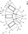
- Fig. 3
- in einer Schnittdarstellung senkrecht zur axialen Richtung einen weiteren Abschnitt des Rotors, und
- Fig. 4
- schematisch den Rotor in einer Draufsicht.
- Fig. 1
- schematically in a sectional view along an axial direction an electric motor with a rotor,
- Fig. 2
- in a sectional view perpendicular to the axial direction of a portion of the rotor,
- Fig. 3
- in a sectional view perpendicular to the axial direction another portion of the rotor, and
- Fig. 4
- schematically the rotor in a plan view.
Einander entsprechende Teile sind in allen Figuren mit den gleichen Bezugszeichen versehen.Corresponding parts are provided in all figures with the same reference numerals.
In
Die Magneten 14 sind mittels einer Elektronik 16 bestromt, die innerhalb eines Elektronikgehäuses 18 angeordnet ist, das an einer Stirnseite des hohlzylindrisch ausgestalteten Gehäuses 8 angeordnet ist. Das Elektronikgehäuse 18 ist hierbei mittels eines B-seitigen Lagerschilds 20 von dem Gehäuse 8 getrennt oder auf das Gehäuse 8 aufgesetzt. Die dem B-seitigen Lager 20 gegenüberliegende Seite des Gehäuses 8 ist mittels eines A-seitigen Lagerschilds 22 verschlossen. An dem A-seitigen Lagerschild 22 und dem B-seitigen Lagerschild 20 ist jeweils ein Lager 24 in Form eines Kugellagers angebunden, mittels dessen eine Welle 26 eines Rotors 28 drehbar um die Rotationsachse 4 gelagert ist. Die Welle 26 ist aus einem Stahl erstellt und befindet sich auf der Rotationsachse 4.The
Der Rotor 28 weist ferner einen Abschnitt 30 und einen zweiten Abschnitt 32 auf, wobei der Abschnitt 30 in
Der Abschnitt 30 weist eine erste Anzahl an Magneten 36 auf. Die erste Anzahl ist zehn und die Magnete 36 des Abschnitts 30 sind Permanentmagneten, die aus einem Ferrit gefertigt und quaderförmig ausgestaltet sind. Die Magnete 36 sind hierbei zueinander baugleich und weisen in der axialen Richtung 6 die Ausdehnung des Abschnitts 30 auf. Ferner sind die Magneten 36 drehsymmetrisch bezüglich der Rotationsachse 4 und in der axialen Richtung 6 angeordnet sowie zueinander beabstandet. Die Magnete 36 des Abschnitts 30 sind somit zueinander bezüglich der Rotationsachse 4 um einen Winkel von 36° versetzt. Die Magneten 36 verlaufen in einer radialen Richtung 38. Mit anderen Worten weist der Abschnitt 30 ein sogenanntes "Speichen"-Design ("Spoke"-Design) auf.The
In einer tangentialen Richtung 40 ist zwischen jeweils benachbarten Magneten 36 jeweils ein erster Bereich 42 eines Polschuhs 44 des Abschnitts 30 angeordnet. Somit weist der Abschnitt 30 ebenfalls insgesamt zehn derartige Polschuhe 44 auf, die zueinander beabstandet und in der axialen Richtung 6 angeordnet sind. Der Querschnitt jedes ersten Bereichs 42 ist ein Ringsegment, an dessen Enden in der radialen Richtung ein jeweils in der tangentialen Richtung 40 verlaufender Vorsprung 46 angebunden ist. Der erste Bereich 42 jedes Polschuhs 44 liegt in der tangentialen Richtung 40 mechanisch direkt an den benachbarten Magneten 36 an, und die Vorsprünge 46 sind bezüglich der benachbarten Magneten 36 in der radialen Richtung 38 versetzt und liegen ebenfalls an den jeweils benachbarten Magneten 36 an. Somit werden die Magneten 36 mittels der jeweils benachbarten Polschuhe 44 stabilisiert und gehalten. Jeder erste Bereich 42 ist bezüglich einer ersten radialen Geraden 48, also einer Geraden, die die Rotationsachse 4 schneidet, achsensymmetrisch, wobei auch die Vorsprünge 46 bezüglich der ersten radialen Geraden 48 symmetrisch sind. Die Magneten 36 des Rotors 28 sind in der tangentialen Richtung 40 magnetisiert, wobei jeweils gleiche Magnetpole aufeinander zu gerichtet sind. Somit treten die mittels der Magneten 36 des Rotors 28 bereitgestellten Magnetfeldlinien bei den ersten Bereichen 42, und hierbei hauptsächlich im Umfeld der ersten radialen Geraden 48m senkrecht aus diesen aus.In a
Jeder Polschuh 44 weist ferner einen zweiten Bereich 50 auf, der bezüglich des jeweiligen ersten Bereichs 42 in der radialen Richtung 38 nach innen versetzt und an diesem angebunden ist. Der zweite Bereich 50 besteht aus einem in der radialen Richtung 38 verlaufenden Steg, dessen eines Ende an dem jeweiligen ersten Bereich 42 angebunden ist, und dessen weiteres Ende 52, also das dem ersten Bereich 42 gegenüberliegende Ende, schwalbenschwanzförmig ausgestaltet ist und somit einen im Wesentliche trapezförmigen Querschnitt aufweist. Die Aufweitung ist hierbei von dem jeweiligen ersten Bereich 42 weg gerichtet. Das Ende 52 liegt formschlüssig in jeweils einer zugeordneten Nut 54 der Welle 26 ein, die in der axialen Richtung 6 verläuft. Somit ist jeder zweite Bereich 50 mit jeweils einer zugeordneten Nut 54 an der Welle 26 angebunden, und auch jeder Polschuh 44 ist somit mittels der jeweiligen Nut 54 an der Welle 26 befestigt. Der Steg 50 jedes Polschuhs 44 ist symmetrisch bezüglich einer jeweiligen zweiten radialen Geraden 56, die bezüglich der ersten radialen Geraden 48 des gleichen Polschuhs 44 um einen Winkel 58 verschwenkt ist. Folglich ist jedem Polschuh 44 eine der ersten Geraden 48 und eine der zweiten Geraden 56 zugeordnet, die sich jeweils auf der Rotationsachse 4 schneiden, und zwischen denen der Winkel 58 gebildet ist.Each
Hierbei ist der erste Bereich 42 jedes Polschuhs 44 symmetrisch bezüglich der jeweiligen ersten Geraden 48 und asymmetrisch bezüglich der jeweiligen zweiten Geraden 56, und der zweite Bereich 50 ist symmetrisch bezüglich der jeweiligen zweiten Geraden 56 und asymmetrisch bezüglich der jeweiligen ersten Geraden 48. Folglich ist der Steg bezüglich des Ringsegments seitlich versetzt, wobei die Versetzung in der tangentialen Richtung 40 bei allen Polschuhen 44 in die gleiche Richtung, in diesem Beispiel im Uhrzeigersinn, ist. Der Winkel 58 ist gleich dem Bruch aus 90° und dem kleinsten gemeinsamen Vielfachen der ersten Anzahl und der zweiten Anzahl, also der Anzahl der Magneten 36 des Rotors 28 und der Anzahl der Magneten 14 des Stators 10. Somit ist der Winkel 58 gleich 90°/60 und folglich gleich 1,5°.Here, the
Jeder Polschuh 44 ist mittels eines Blechpakets gebildet, dessen Bleche in der axialen Richtung 6 aufeinander gestapelt sind. Hierbei weist jedes Blech die Form des Querschnitts des Polschuhs 44 auf, der in
Zwischen der Welle 26 und den ersten Bereichen 42 ist eine Anzahl an Stützelementen 60 des Abschnitts 30 angeordnet, die den zwischen der Welle 26 und den Polschuhen 44 gebildeten Raum vollständig ausfüllen. Die Stützelemente 60 sind aus einem para- oder diamagnetischen Material gefertigt, insbesondere aus einem Kunststoff. Mittels der Stützelemente 60 wird hierbei ein Abknicken der ersten Bereiche 42 aufgrund der vergleichsweise filigranen Anbindung an der Welle 26 mittels der zweiten Bereiche 50 vermieden, sodass die Stabilität des Rotors 28 erhöht ist. Da die Stützelemente 60 aus dem para- oder diamagnetischen Material gefertigt sind, breiten sich hierbei die mittels der Magneten 36 bereitgestellten Magnetfelder vergleichsweise gering in diesen aus, sodass ein magnetischer Kurzschluss lediglich mittels der zweiten Bereiche 50 und der Welle 26 erfolgen kann. Folglich wird der Großteil der Magnetfeldlinien der Magneten 36 in den Luftspalt 34 und somit zu dem Stator 10 gedrängt, was einen Wirkungsgrad erhöht.Between the
Der Abschnitt 30 und der weitere Abschnitt 32 sind zueinander baugleich, wobei der weitere Abschnitt 32 bezüglich des Abschnitts 30 um eine radiale Achse um 180° gedreht ist. Somit sind bei den Polschuhen 44 des weiteren Abschnitt 32 die zweiten Bereiche 50 bezüglich der jeweiligen ersten radialen Geraden 38 entgegen des Uhrzeigersinns versetzt.The
In
Zusammenfassend ist mittels der Stützelemente 60 ein magnetischer Kurzschluss unterbunden, und die Stützelemente 60 sind beispielsweise aus einem Kunststoff erstellt. Somit ist es ermöglicht, die Breite des Stegs der zweiten Bereiche 50 verbreitert auszugestalten, weswegen eine mechanische Belastung verringert ist, wobei die elektrische Leistung der elektrischen Maschine 2 unverändert bleibt oder steigt. Aufgrund des Versatzes jedes zweiten Bereichs 50 bezüglich des jeweils zugeordneten ersten Bereichs 42 um den Winkel 58 ist der Rotor 28 schräg aufgebaut, weswegen ein Rastmoment reduziert ist. Hierbei werden die Abschnitte 30, 32 um 180° gedreht montiert. Aufgrund der Stützelemente 60 ist eine mechanische Beanspruchung verbessert und eine Leistung der elektrischen Maschine 2 erhöht. Aufgrund des Versatzes der zweiten Bereiche 50 werden Rastmomente reduziert, sodass der Rotor 28 geschrägt ist, und wobei eine Montage vereinfacht ist.In summary, a magnetic short circuit is prevented by means of the
Folglich ist jeder Abschnitt 30, 32 im Wesentlichen segmentiert, weswegen ein Werkzeug zur Herstellung der Polschuhe 44 vergleichsweise klein ausgestaltet sein kann, auch wenn die elektrische Maschine 2, insbesondere der Rotor 28, einen vergleichsweise großen Durchmesser aufweist. Ferner ist aufgrund des zweiten Bereiches 50 eine Leistungssteigerung möglich. Die Polschuhe 44 werden auf die Welle 26 gesteckt, wobei je nach Anzahl der Pole die Anzahl der Polschuhe 44 und somit der ersten und zweiten Bereiche 42, 50 variiert. Zwischen den ersten Bereichen 42 wird in tangentialer Richtung 40 bei Montage die bereits magnetisierten Magnete 36 positioniert. Die zweiten Bereiche 50 sind bezüglich der jeweiligen ersten Geraden 48 um den Winkel 58 versetzt. Aufgrund der Drehung des zweiten Abschnitts 32 bezüglich des Abschnitts 30 um 180° ist eine Schrägung des Rotors 28 realisiert, weswegen Rastmomente reduziert werden. Der Winkel 58 ist hierbei abhängig von der Anzahl der Magneten 14 (elektrischen Spulen) des Stators 10 und der Anzahl der Magneten 36 des Rotors 28 und somit von der Polpaarzahl und der Nutpaarzahl. Der Winkel 58 ist hierbei der Bruch aus 90° und dem kleinsten gemeinsamen Vielfachen aus der Nutpaarzahl und dem Doppelten der Polpaarzahl, also der Polzahl. Vorzugsweise sind im Rotor 28 eine geradzahlige Anzahl von Magneten 36 gesteckt. Zur Realisierung von geschrägten Rotoren 28 sind pro Pol ebenfalls eine gradzahlige Anzahl an Magnete 36 pro Pol vorhanden.Consequently, each
Die Erfindung ist nicht auf das vorstehend beschriebene Ausführungsbeispiel beschränkt. Vielmehr können auch andere Varianten der Erfindung von dem Fachmann hieraus abgeleitet werden, ohne den Gegenstand der Erfindung zu verlassen. Insbesondere sind ferner alle im Zusammenhang mit dem Ausführungsbeispiel beschriebene Einzelmerkmale auch auf andere Weise miteinander kombinierbar, ohne den Gegenstand der Erfindung zu verlassen.The invention is not limited to the embodiment described above. Rather, other variants of the invention can be derived therefrom by the person skilled in the art without departing from the subject matter of the invention. In particular, all the individual features described in connection with the exemplary embodiment can also be combined with one another in other ways, without departing from the subject matter of the invention.
- 22
- elektrische Maschineelectric machine
- 44
- Rotationsachseaxis of rotation
- 66
- axiale Richtungaxial direction
- 88th
- Gehäusecasing
- 1010
- Statorstator
- 1212
- Blechpaketlaminated core
- 1414
- Magnet des StatorsMagnet of the stator
- 1616
- Elektronikelectronics
- 1818
- Elektronikgehäuseelectronics housing
- 2020
- B-seitiges LagerschildB-side end shield
- 2222
- A-seitiges LagerschildA-side end shield
- 2424
- Lagerwarehouse
- 2626
- Wellewave
- 2828
- Rotorrotor
- 3030
- Abschnittsection
- 3232
- weiterer Abschnittanother section
- 3434
- Luftspaltair gap
- 3636
- Magnet des RotorsMagnet of the rotor
- 3838
- radiale Richtungradial direction
- 4040
- tangentiale Richtungtangential direction
- 4242
- erster Bereichfirst area
- 4444
- Polschuhpole
- 4646
- Vorsprunghead Start
- 4848
- erste radiale Geradefirst radial line
- 5050
- zweiter Bereichsecond area
- 5252
- EndeThe End
- 5454
- Nutgroove
- 5656
- zweite radiale Geradesecond radial line
- 5858
- Winkelcorner
- 6060
- Stützelementsupport element
Claims (11)
gekennzeichnet durch
einen weiteren Abschnitt (32), der bezüglich des Abschnitts (30) in der axialen Richtung (6) versetzt ist, und der baugleich zu dem Abschnitt (30) und bezüglich des Abschnitts (30) um eine radialen Achse um 180 ° gedreht ist, wobei die ersten Bereiche (42) des Abschnitts (30) und die ersten Bereiche (42) des weiteren Abschnitts (32) in der tangentialer Richtung (40) zueinander versetzt sind.Rotor (28) according to claim 1,
marked by
another portion (32) which is offset with respect to the portion (30) in the axial direction (6) and which is identical in construction to the portion (30) and rotated by 180 ° about a radial axis with respect to the portion (30), wherein the first portions (42) of the portion (30) and the first portions (42) of the further portion (32) are offset from one another in the tangential direction (40).
dadurch gekennzeichnet,
dass jeder der zweiten Bereiche (50) des Abschnitts (30) mit jeweils einem der zweiten Bereiche (50) des weiteren Abschnitts (32) fluchtet.Rotor (28) according to claim 2,
characterized,
in that each of the second regions (50) of the section (30) is aligned with one of the second regions (50) of the further section (32).
dadurch gekennzeichnet,
dass der Querschnitt jedes ersten Bereichs (42) ein Ringsegment aufweist, an dem ein in der tangentialen Richtung (40) verlaufender Vorsprung (46) angebunden ist, der bezüglich eines der benachbarten Magneten (36) in der radialen Richtung (38) versetzt ist.Rotor (28) according to one of claims 1 to 3,
characterized,
in that the cross-section of each first region (42) has a ring segment on which a projection (46) running in the tangential direction (40) is connected, which is offset with respect to one of the adjacent magnets (36) in the radial direction (38).
dadurch gekennzeichnet,
dass jeder erste Bereich (42) mechanisch direkt an den beiden zugordneten Magneten (36) anliegt.Rotor (28) according to one of claims 1 to 4,
characterized,
that each first portion (42) mechanically directly at the two zugordneten magnet (36) is applied.
dadurch gekennzeichnet,
dass jeder zweite Bereich (50) einen in der radialen Richtung (38) verlaufenden Steg aufweist, der auf der dem zugeordneten ersten Bereich (42) gegenüberliegenden Ende (52) an der Welle befestigt ist.Rotor (28) according to one of claims 1 to 5,
characterized,
in that each second region (50) has a web extending in the radial direction (38), which is fastened to the shaft on the end (52) opposite the associated first region (42).
dadurch gekennzeichnet,
dass das Ende (52) schalbenschwanzförmig ausgestaltet ist.Rotor (28) according to claim 6,
characterized,
that the end (52) is designed like a dovetail.
dadurch gekennzeichnet,
dass jeder zweite Bereich (50) symmetrisch bezüglich einer jeweiligen zweiten radialen Geraden (56) ist, die bezüglich der jeweils zugeordneten ersten radialen Geraden (48) um einen Winkel (58) verschwenkt ist.Rotor (28) according to one of claims 1 to 7,
characterized,
in that each second region (50) is symmetrical with respect to a respective second radial straight line (56) which is pivoted about an angle (58) with respect to the respectively associated first radial straight line (48).
dadurch gekennzeichnet,
dass zwischen der Welle (26) und den ersten Bereichen (42) eine Anzahl an Stützelementen (60) aus einem para- oder diamagnetischen Material angeordnet ist.Rotor (28) according to one of claims 1 to 8,
characterized,
that a number of supporting elements (60) made of a para- or diamagnetic material between the shaft (26) and the first regions (42).
Applications Claiming Priority (1)
| Application Number | Priority Date | Filing Date | Title |
|---|---|---|---|
| DE102017222099.6A DE102017222099A1 (en) | 2017-12-06 | 2017-12-06 | Rotor of an electric machine |
Publications (1)
| Publication Number | Publication Date |
|---|---|
| EP3496236A1 true EP3496236A1 (en) | 2019-06-12 |
Family
ID=64277597
Family Applications (1)
| Application Number | Title | Priority Date | Filing Date |
|---|---|---|---|
| EP18205715.8A Withdrawn EP3496236A1 (en) | 2017-12-06 | 2018-11-12 | Rotor of an electric machine |
Country Status (3)
| Country | Link |
|---|---|
| EP (1) | EP3496236A1 (en) |
| CN (1) | CN109888948A (en) |
| DE (1) | DE102017222099A1 (en) |
Cited By (1)
| Publication number | Priority date | Publication date | Assignee | Title |
|---|---|---|---|---|
| WO2023217693A1 (en) * | 2022-05-09 | 2023-11-16 | eMoSys GmbH | Fluid-cooled, multi-phase permanently excited synchronous machine |
Citations (4)
| Publication number | Priority date | Publication date | Assignee | Title |
|---|---|---|---|---|
| WO2011012133A2 (en) * | 2009-07-29 | 2011-02-03 | Joachim Sabinski | Permanent magnet rotors having permanent magnets that are oriented radially and arranged in a protected and sunken manner, the magnetic poles being oriented tangentially, as an internal rotor embodiment or external rotor embodiment of rotating electric machines and method for assembling said permanent magnet rotors |
| DE102010061778A1 (en) * | 2010-11-23 | 2012-05-24 | Robert Bosch Gmbh | Spokes rotor for e.g. electric machine, has body fixed at shaft with sleeve, where shaft and/or sleeve is made of diamagnetic material and/or paramagnetic material with permeability number smaller than twelve |
| US20140084734A1 (en) * | 2012-09-26 | 2014-03-27 | Hitachi Automotive Systems, Ltd. | Rotating Electrical Machine, Method for Manufacturing Magnetic Pole Piece |
| DE102014226047A1 (en) * | 2014-12-16 | 2016-06-16 | Robert Bosch Gmbh | Spoke rotor with encapsulation |
Family Cites Families (4)
| Publication number | Priority date | Publication date | Assignee | Title |
|---|---|---|---|---|
| DE3016540A1 (en) * | 1980-04-29 | 1981-11-05 | Institut po Elektropromišlenost, Sofija | Rotary inductor for electrical machine - has permanent magnet rotors with magnets arranged radially with intermediate tapered pole pieces |
| JP4070674B2 (en) * | 2003-07-31 | 2008-04-02 | 株式会社東芝 | Reluctance rotor |
| CN104518584B (en) * | 2013-09-27 | 2017-01-04 | 安徽明腾永磁机电设备有限公司 | Permanent magnetic electric machine rotor iron core |
| DE102014001243A1 (en) | 2014-02-03 | 2015-08-06 | Baumüller Directmotion Gmbh | Electric machine |
-
2017
- 2017-12-06 DE DE102017222099.6A patent/DE102017222099A1/en not_active Withdrawn
-
2018
- 2018-11-12 EP EP18205715.8A patent/EP3496236A1/en not_active Withdrawn
- 2018-12-04 CN CN201811471906.6A patent/CN109888948A/en active Pending
Patent Citations (4)
| Publication number | Priority date | Publication date | Assignee | Title |
|---|---|---|---|---|
| WO2011012133A2 (en) * | 2009-07-29 | 2011-02-03 | Joachim Sabinski | Permanent magnet rotors having permanent magnets that are oriented radially and arranged in a protected and sunken manner, the magnetic poles being oriented tangentially, as an internal rotor embodiment or external rotor embodiment of rotating electric machines and method for assembling said permanent magnet rotors |
| DE102010061778A1 (en) * | 2010-11-23 | 2012-05-24 | Robert Bosch Gmbh | Spokes rotor for e.g. electric machine, has body fixed at shaft with sleeve, where shaft and/or sleeve is made of diamagnetic material and/or paramagnetic material with permeability number smaller than twelve |
| US20140084734A1 (en) * | 2012-09-26 | 2014-03-27 | Hitachi Automotive Systems, Ltd. | Rotating Electrical Machine, Method for Manufacturing Magnetic Pole Piece |
| DE102014226047A1 (en) * | 2014-12-16 | 2016-06-16 | Robert Bosch Gmbh | Spoke rotor with encapsulation |
Cited By (1)
| Publication number | Priority date | Publication date | Assignee | Title |
|---|---|---|---|---|
| WO2023217693A1 (en) * | 2022-05-09 | 2023-11-16 | eMoSys GmbH | Fluid-cooled, multi-phase permanently excited synchronous machine |
Also Published As
| Publication number | Publication date |
|---|---|
| CN109888948A (en) | 2019-06-14 |
| DE102017222099A1 (en) | 2019-06-06 |
Similar Documents
| Publication | Publication Date | Title |
|---|---|---|
| EP0286905B1 (en) | Electronically commutated brushless dc motor | |
| EP2619883B1 (en) | Machine component for an electrical machine | |
| DE10309776A1 (en) | Permanent magnet rotor designed to minimize cogging effect, includes magnets in pockets with air gaps and laminated rotor pack with thinned sections | |
| EP3499687B1 (en) | Rotor of an electric machine | |
| EP3659240B1 (en) | Rotor of an electric machine | |
| EP3522336A1 (en) | Rotor | |
| DE102008019734A1 (en) | Electric machine and rotor for the same | |
| DE60201937T2 (en) | Electric machine with external rotor | |
| EP3309934A1 (en) | Electric machine | |
| EP2319164B1 (en) | Rotor for an electric machine with a reduced cogging torque | |
| EP3669440B1 (en) | Rotor of an electric machine | |
| EP3496236A1 (en) | Rotor of an electric machine | |
| DE102015110652B4 (en) | ROTOR STATOR ARRANGEMENT FOR A HYBRID ROTATED SYNCHRONOUS MACHINE AND A ROTOR THEREFOR | |
| EP2652862B1 (en) | Machine component for an electrical machine | |
| EP3667871A1 (en) | Electric machine | |
| WO2018019487A1 (en) | Rotor for an electric rotating machine | |
| EP2296253A2 (en) | Electric motor with permanent magnet excitation with reduced load torque | |
| DE102019005465A1 (en) | ELECTRIC ROTATION MACHINE, EQUIPPED WITH A ROTOR REDUCED DIMENSION | |
| EP3679641B1 (en) | Rotating electric machine | |
| EP3579383B1 (en) | Torque-optimised multipolar rotor for an electric motor | |
| DE112016005481T5 (en) | Claw rotor of a rotary electric machine with claws having an arcuate chamfer | |
| DE102016111645B9 (en) | Powerful brushless micro drive | |
| EP2871752A1 (en) | Rotor of a rotational permanently excited synchronous motor | |
| DE102019005464A1 (en) | ELECTRIC ROTATION MACHINE, EQUIPPED WITH A ROTOR REDUCED INERTIA | |
| DE102022106874A1 (en) | Reluctance machine |
Legal Events
| Date | Code | Title | Description |
|---|---|---|---|
| PUAI | Public reference made under article 153(3) epc to a published international application that has entered the european phase |
Free format text: ORIGINAL CODE: 0009012 |
|
| AK | Designated contracting states |
Kind code of ref document: A1 Designated state(s): AL AT BE BG CH CY CZ DE DK EE ES FI FR GB GR HR HU IE IS IT LI LT LU LV MC MK MT NL NO PL PT RO RS SE SI SK SM TR |
|
| AX | Request for extension of the european patent |
Extension state: BA ME |
|
| 17P | Request for examination filed |
Effective date: 20191205 |
|
| RBV | Designated contracting states (corrected) |
Designated state(s): AL AT BE BG CH CY CZ DE DK EE ES FI FR GB GR HR HU IE IS IT LI LT LU LV MC MK MT NL NO PL PT RO RS SE SI SK SM TR |
|
| 17Q | First examination report despatched |
Effective date: 20200421 |
|
| STAA | Information on the status of an ep patent application or granted ep patent |
Free format text: STATUS: THE APPLICATION HAS BEEN WITHDRAWN |
|
| 18W | Application withdrawn |
Effective date: 20200615 |