EP3496114A1 - Method for producing soft magnetic material - Google Patents
Method for producing soft magnetic material Download PDFInfo
- Publication number
- EP3496114A1 EP3496114A1 EP17837033.4A EP17837033A EP3496114A1 EP 3496114 A1 EP3496114 A1 EP 3496114A1 EP 17837033 A EP17837033 A EP 17837033A EP 3496114 A1 EP3496114 A1 EP 3496114A1
- Authority
- EP
- European Patent Office
- Prior art keywords
- temperature
- amorphous alloy
- alloy
- amorphous
- sec
- Prior art date
- Legal status (The legal status is an assumption and is not a legal conclusion. Google has not performed a legal analysis and makes no representation as to the accuracy of the status listed.)
- Granted
Links
Images



Classifications
-
- C—CHEMISTRY; METALLURGY
- C21—METALLURGY OF IRON
- C21D—MODIFYING THE PHYSICAL STRUCTURE OF FERROUS METALS; GENERAL DEVICES FOR HEAT TREATMENT OF FERROUS OR NON-FERROUS METALS OR ALLOYS; MAKING METAL MALLEABLE, e.g. BY DECARBURISATION OR TEMPERING
- C21D6/00—Heat treatment of ferrous alloys
-
- C—CHEMISTRY; METALLURGY
- C22—METALLURGY; FERROUS OR NON-FERROUS ALLOYS; TREATMENT OF ALLOYS OR NON-FERROUS METALS
- C22C—ALLOYS
- C22C33/00—Making ferrous alloys
- C22C33/003—Making ferrous alloys making amorphous alloys
-
- C—CHEMISTRY; METALLURGY
- C22—METALLURGY; FERROUS OR NON-FERROUS ALLOYS; TREATMENT OF ALLOYS OR NON-FERROUS METALS
- C22C—ALLOYS
- C22C38/00—Ferrous alloys, e.g. steel alloys
- C22C38/002—Ferrous alloys, e.g. steel alloys containing In, Mg, or other elements not provided for in one single group C22C38/001 - C22C38/60
-
- C—CHEMISTRY; METALLURGY
- C22—METALLURGY; FERROUS OR NON-FERROUS ALLOYS; TREATMENT OF ALLOYS OR NON-FERROUS METALS
- C22C—ALLOYS
- C22C38/00—Ferrous alloys, e.g. steel alloys
- C22C38/08—Ferrous alloys, e.g. steel alloys containing nickel
-
- C—CHEMISTRY; METALLURGY
- C22—METALLURGY; FERROUS OR NON-FERROUS ALLOYS; TREATMENT OF ALLOYS OR NON-FERROUS METALS
- C22C—ALLOYS
- C22C38/00—Ferrous alloys, e.g. steel alloys
- C22C38/10—Ferrous alloys, e.g. steel alloys containing cobalt
-
- C—CHEMISTRY; METALLURGY
- C22—METALLURGY; FERROUS OR NON-FERROUS ALLOYS; TREATMENT OF ALLOYS OR NON-FERROUS METALS
- C22C—ALLOYS
- C22C38/00—Ferrous alloys, e.g. steel alloys
- C22C38/12—Ferrous alloys, e.g. steel alloys containing tungsten, tantalum, molybdenum, vanadium, or niobium
-
- C—CHEMISTRY; METALLURGY
- C22—METALLURGY; FERROUS OR NON-FERROUS ALLOYS; TREATMENT OF ALLOYS OR NON-FERROUS METALS
- C22C—ALLOYS
- C22C38/00—Ferrous alloys, e.g. steel alloys
- C22C38/16—Ferrous alloys, e.g. steel alloys containing copper
-
- C—CHEMISTRY; METALLURGY
- C22—METALLURGY; FERROUS OR NON-FERROUS ALLOYS; TREATMENT OF ALLOYS OR NON-FERROUS METALS
- C22C—ALLOYS
- C22C45/00—Amorphous alloys
- C22C45/02—Amorphous alloys with iron as the major constituent
-
- H—ELECTRICITY
- H01—ELECTRIC ELEMENTS
- H01F—MAGNETS; INDUCTANCES; TRANSFORMERS; SELECTION OF MATERIALS FOR THEIR MAGNETIC PROPERTIES
- H01F1/00—Magnets or magnetic bodies characterised by the magnetic materials therefor; Selection of materials for their magnetic properties
- H01F1/01—Magnets or magnetic bodies characterised by the magnetic materials therefor; Selection of materials for their magnetic properties of inorganic materials
- H01F1/03—Magnets or magnetic bodies characterised by the magnetic materials therefor; Selection of materials for their magnetic properties of inorganic materials characterised by their coercivity
- H01F1/12—Magnets or magnetic bodies characterised by the magnetic materials therefor; Selection of materials for their magnetic properties of inorganic materials characterised by their coercivity of soft-magnetic materials
- H01F1/14—Magnets or magnetic bodies characterised by the magnetic materials therefor; Selection of materials for their magnetic properties of inorganic materials characterised by their coercivity of soft-magnetic materials metals or alloys
- H01F1/147—Alloys characterised by their composition
- H01F1/153—Amorphous metallic alloys, e.g. glassy metals
- H01F1/15341—Preparation processes therefor
- H01F1/1535—Preparation processes therefor by powder metallurgy, e.g. spark erosion
-
- C—CHEMISTRY; METALLURGY
- C22—METALLURGY; FERROUS OR NON-FERROUS ALLOYS; TREATMENT OF ALLOYS OR NON-FERROUS METALS
- C22C—ALLOYS
- C22C2200/00—Crystalline structure
- C22C2200/02—Amorphous
-
- C—CHEMISTRY; METALLURGY
- C22—METALLURGY; FERROUS OR NON-FERROUS ALLOYS; TREATMENT OF ALLOYS OR NON-FERROUS METALS
- C22C—ALLOYS
- C22C2202/00—Physical properties
- C22C2202/02—Magnetic
Definitions
- the present invention relates to a method for producing a soft magnetic material. More particularly, the present invention relates to a method for producing a soft magnetic material having both high saturation magnetization and low coercive force.
- Soft magnetic materials used in the cores of components such as motors or reactors are required to demonstrate both high saturation magnetization and low coercive force in order to enhance the performance of these components.
- Soft magnetic materials having high saturation magnetization includes Fe-based nanocrystalline soft magnetic materials.
- Fe-based nanocrystalline soft magnetic materials refer to soft magnetic materials composed mainly of Fe in which nanocrystals are dispersed in the material at 30% by volume or more.
- Patent Document 1 discloses an Fe-based nanocrystalline soft magnetic material represented by the compositional formula Fe 100-p-q-r-s Cu p B q Si r Sn s (wherein, p, q, r and s are in atomic percent (at%) and satisfy the relational expressions of 0.6 ⁇ p ⁇ 1.6, 6 ⁇ q ⁇ 20, 0 ⁇ r ⁇ 17 and 0.005 ⁇ s ⁇ 24).
- Patent Document 1 discloses that an Fe-based nanocrystalline soft magnetic material is obtained by heat-treating a thin ribbon having a composition represented by Fe 100-p-q-r-s Cu p B q Si r Sn s and amorphous phase.
- Patent Document 1 Japanese Unexamined Patent Publication No. 2014-240516
- Fe-based nanocrystalline soft magnetic materials have high saturation magnetization since they have Fe as a main component thereof.
- Fe-based nanocrystalline soft magnetic materials are obtained by heat-treating (it is also referred to "annealing"; the same shall apply hereinafter) a ribbon having an amorphous phase. If the Fe content in the amorphous ribbon is high, a crystalline phase ( ⁇ -Fe) is easily formed from the amorphous phase and the crystalline phase easily becomes coarse as a result of undergoing grain growth. Therefore, the addition of an element that inhibits grain growth in the material reduces the Fe content in the material corresponding to the amount of that element added, thereby lowering saturation magnetization.
- the inventors of the present invention found the problem in which, although high saturation magnetization is obtained when the main component of a soft magnetic material is Fe, since a crystalline phase forms from the amorphous phase during heat treatment and that crystalline phase becomes coarse as a result of grain growth, it is difficult to obtain low coercive force.
- an object of the present invention is to provide a method for producing a soft magnetic material having both high saturation magnetization and low coercive force.
- the inventors of the present invention make extensive studies to solve the aforementioned problem, thereby leading to completion of the present invention.
- the gist thereof is as indicated below.
- the present invention even if the main component of a alloy having an amorphous phase is Fe in order to obtain high saturation magnetization, by rapidly raising the temperature of that alloy to a temperature equal to or higher than the crystallization starting temperature and lower than the temperature at which Fe-B compounds start to form and then cooling immediately, or holding for a short period of time at that temperature, the crystalline phase becomes increasingly fine allowing the obtaining of low coercive force.
- a method can be provided for producing a soft magnetic material having both high saturation magnetization and low coercive force.
- a alloy having Fe as the main component thereof and an amorphous phase is rapidly raised to a temperature equal to or higher than the crystallization starting temperature and lower than the temperature at which Fe-B compounds start to form, and then holding at that temperature for a short period of time.
- alloy having Fe as the main component thereof refers to the content of Fe in the material being 50 at% or more.
- a “alloy having an amorphous phase” refers to a alloy containing 50% by volume or more of an amorphous phase in that alloy, and this may also be simply referred to as an "amorphous alloy”.
- the “alloy” has such forms as ribbon, flake, granules, and bulk and the like.
- the following phenomenon is thought to occur in the amorphous alloy when the amorphous alloy is subjected to heat treatment at a temperature equal to or higher than the crystallization starting temperature and lower than the temperature at which Fe-B compounds start to form.
- a crystalline phase is formed from the amorphous phase when the amorphous alloy is raise in temperature to a temperature equal to or higher than the crystallization starting temperature.
- the phenomenon that occurs during the process thereof is explained by dividing into the case in which elements serving as heterogeneous nucleation sites are present in the amorphous alloy, and the case in which such elements are not present in the amorphous alloy.
- elements that serve as heterogeneous nucleation sites are elements that do not readily form a solid solution with Fe.
- An example of an element that serves as a heterogeneous nucleation site and that is not soluble in Fe is Cu.
- Cu becomes a nucleation site, heterogeneous nucleation occurs at these Cu clusters as a starting point, and the crystalline phase is refined.
- the amorphous alloy contains Cu, adequate nucleation occurs even in the case of raising the temperature of the amorphous alloy at a low rate (about 1.7°C/sec), and a fine crystalline phase is thought to be obtained.
- the coarsening of the microstructure is thought to be avoided and a fine crystalline phase is thought to be obtained by rapidly raising the temperature of the amorphous alloy (10°C/sec or more) and cooling immediately or holding at that temperature for a short period of time (0 seconds to 80 seconds).
- the details thereof are as indicated below.
- the holding time being 0 second means immediately cooling or stopping holding after rapidly raising the temperature.
- the homogeneous nucleation rate is governed by the atomic transport and the critical nucleus size.
- a high atomic transport and a small critical nucleus size result in a high homogeneous nucleation rate, leading to a finer microstructure.
- it is effective to induce a supercooled liquid region in the amorphous solid. This is because the viscous flow in supercooled liquid is massive and the strain energy due to nucleation in a supercooled liquid is considerably smaller than that in amorphous solids. Hence, a higher number of embryos becomes nuclei when supercooled liquid regions are realized.
- the conventional annealing results in crystallization of the amorphous solid in relatively low temperatures where the transition from solid to supercooled liquid is limited.
- the homogeneous nucleation under conventional heating rates is very limited. Contrarily, the crystallization onset temperature is raised by rapid heating. Hence, a high homogeneous nucleation rate is realized because the amorphous phase is retained at higher temperatures where the transition of the amorphous solid to a supercooled liquid takes place vigorously. As a result, nucleation frequency becomes higher.
- the temperature of an amorphous alloy is rapidly raised (10°C/ sec or more) to the crystallization starting temperature or higher in order to allow atomic transport to occur resulting in vigorous nucleation in a region formed in a supercooled state as mentioned above. Since the rate of grain growth also increases when the temperature of the amorphous alloy is raised rapidly, the duration of grain growth is shortened by shorting holding time (0 seconds to 80 seconds). From the viewpoint of atomic transport, the temperature of the amorphous alloy is preferably raised to a temperature that is as high as possible beyond the crystallization starting temperature thereof. However, if the temperature of the amorphous alloy reaches the temperature at which Fe-B compounds start to form, those Fe-B compounds are formed.
- the temperature of the amorphous alloy is preferably rapidly raised to a temperature that is equal to or higher than the crystallization starting temperature and lower than the temperature at which Fe-B compounds start to form.
- the temperature of the amorphous alloy is required to be rapidly raised to a temperature range that is equal to or higher than the crystallization starting temperature and lower than the temperature at which Fe-B compounds start to form.
- a temperature range that is equal to or higher than the crystallization starting temperature and lower than the temperature at which Fe-B compounds start to form.
- there are no particular problems with rapidly raising the temperature of the amorphous alloy in a temperature range lower than the crystallization starting temperature may be increased rapidly starting from when the temperature of the amorphous alloy is lower than the crystallization starting temperature, and the temperature may be continued to be raised rapidly after the amorphous alloy has reached the crystallization starting temperature.
- Rapidly raising the temperature as previously described is effective when an element serving as a heterogeneous nucleation site is not present in the amorphous alloy.
- an element, such as Cu, serving as a heterogeneous nucleation site is present in the amorphous alloy, it becomes possible to cumulatively obtain the effect of refining crystal grain sizes as a result of Cu serving as a nucleation site, and the effect of refining crystal grains due to remarkable increase of nucleation frequency by rising temperature rapidly.
- an amorphous alloy should be subjected to heat treatment comprising rapidly raising the temperature thereof to a temperature equal to or higher than the crystallization starting temperature and lower than the temperature at which Fe-B compounds start to form followed by immediate cooling or holding at that attained temperature for a short period of time.
- This heat treatment was found to be effective regardless of whether or not an element serving as a heterogeneous nucleation site, such as Cu, is present in the amorphous alloy.
- a alloy having an amorphous phase (amorphous alloy) is prepared.
- the amorphous phase accounts for 50% by volume or more of the amorphous alloy.
- the content of the amorphous phase in the amorphous alloy is preferably 60% by volume or more, 70% by volume or more or 90% by volume or more.
- the amorphous alloy has a composition represented by Compositional Formula 1 or Compositional Formula 2.
- An amorphous alloy having a composition represented by Compositional Formula 1 does not contain an element that serves as a heterogeneous nucleation site.
- An amorphous alloy having a composition represented by Compositional Formula 2 (hereinafter, referred to "amorphous alloy of Compositional Formula 2") contains an element that serves as a heterogeneous nucleation site.
- Compositional Formula 1 is Fe 100-x-y B x M y .
- M represents at least one element selected from Nb, Mo, Ta, W, Ni, Co and Sn, and x and y satisfy the relational expressions of 10 ⁇ x ⁇ 16 and 0 ⁇ y ⁇ 8.
- x and y are in atomic percent (at%), x represents the content of B, and y represents the content of M.
- the amorphous alloy of Compositional Formula 1 has Fe for the main component thereof, and the Fe content thereof is 50 at% or more.
- the content of Fe is represented as the remainder of B and M. From the viewpoint of a soft magnetic material, obtained by rapidly raising the temperature of an amorphous alloy and holding at that temperature, having high saturation magnetization, Fe content is preferably 80 at% or more, 84 at% or more or 88 at% or more.
- the amorphous alloy is obtained by quenching a melt having Fe as the main component thereof.
- B (Boron) promotes the formation of an amorphous phase when the melt is quenched.
- the main phase of the amorphous alloy becomes an amorphous phase if the content of B in an amorphous alloy obtained by quenching the melt is 10 at% or more.
- the main phase of the alloy being an amorphous phase means that the content of the amorphous phase in the alloy is 50% by volume or more.
- the content of B in the amorphous alloy is preferably 11 at% or more and more preferably 12 at% or more.
- Fe-B compound formation upon crystallization of the amorphous phase can be avoided when the content of B in the amorphous alloy is 16 at% or less.
- the content of B in the amorphous alloy is preferably 15 at% or less and more preferably 14 at% or less.
- the amorphous alloy of Compositional Formula 1 may also contain M as necessary.
- M is at least one element selected from Nb, Mo, Ta, W, Ni, Co and Sn.
- the inhibitory effect on the crystalline phase as a result of containing these elements is smaller in comparison with the effect of inhibiting grain growth of the crystalline phase due to the high nucleation frequency.
- the content of Fe in the amorphous alloy decreases resulting in a decrease saturation magnetization.
- the contents of these elements in the amorphous alloy are preferably the minimum required contents.
- the magnitude of induced magnetic anisotropy can be controlled when selecting at least one of Ni and Co among M and the amorphous alloy contains these elements.
- saturation magnetization can also be increased when the amorphous alloy contains Co.
- the aforementioned action is provided corresponding to the content of M.
- Nb, Mo, Ta, W, Sn and P provide an action that inhibits grain growth of the crystalline phase and stabilizes the amorphous phase
- Ni and Co provide the action of controlling the magnitude of induced magnetic anisotropy and increasing saturation magnetization.
- the content of M is preferably 0.2 at% or more and more preferably 0.5 at% or more.
- the content of M is 8 at% or less, the amounts of essential elements of Fe and B in the amorphous alloy do not become excessively low, and as a result, a soft magnetic material obtained by rapidly raising the temperature of the amorphous alloy and holding at that temperature is able to have both high saturation magnetization and low coercive force. Furthermore, in the case of having selected two or more elements for M, the content of M is the total content of these elements.
- the amorphous alloy of Compositional Formula 1 may also contain unavoidable impurities such as S, O or N in addition to Fe, B and M.
- An unavoidable impurity refers to an impurity contained in the raw materials for which the containing thereof cannot be avoided, or an impurity that leads to a remarkable increase in production costs when attempted to be avoided. If such an avoidable impurity is contained, the purity of an alloy of Compositional Formula 1 is preferably 97% by mass or more, more preferably 98% by mass or more and even more preferably 99% by mass or more.
- Compositional Formula 2 is Fe 100-a-b-c B a Cu b M' c .
- M' represents at least one element selected from Nb, Mo, Ta, W, Ni and Co, and a, b and c respectively satisfy the relational expressions 10 ⁇ a ⁇ 16, 0 ⁇ b ⁇ 2 and 0 ⁇ c ⁇ 8.
- a, b and c are in in atomic percent (at%), a represents the content of B, b represents the content of Cu, and c represents the content of M'.
- the amorphous alloy of Compositional Formula 2 has Cu for an essential component thereof in addition to Fe and B.
- the amorphous alloy of Compositional Formula 2 may also contain M' as necessary.
- M' is at least one element selected from Nb, Mo, Ta, W, Ni and Co.
- the amorphous alloy contains Cu
- the Cu becomes a nucleation site during the temperature of amorphous alloy being raised rapidly and held at that temperature, heterogeneous nucleation occurs with its starting point in Cu clusters, and the crystalline phase grains becomes fine.
- the content of Cu in the amorphous alloy is preferably 0.2 at% or more and more preferably 0.5 at% or more.
- the Cu content in the amorphous alloy is 2 at% or less an amorphous alloy can be produced by rapid quenching of the melt without the formation of a crystalline phase.
- the Cu content in the amorphous alloy is preferably 1 at% or less and more preferably 0.7 at% or less.
- the amorphous alloy of Compositional Formula 2 may also contain unavoidable impurities such as S, O and N in addition to Fe, B, Cu and M'.
- An unavoidable impurity refers to an impurity contained in the raw materials for which the containing thereof cannot be avoided, or an impurity that leads to a remarkable increase in production costs when attempted to be avoided.
- the purity of the amorphous alloy of Compositional Formula 2 when such an avoidable impurity is contained is preferably 97% by mass or more, more preferably 98% by mass or more and even more preferably 99% by mass or more.
- the amorphous alloy is heated at a rate of temperature rise of 10°C/sec or more and is held for 0 to 80 seconds at a temperature equal to or higher than the crystallization starting temperature and lower than the temperature at which Fe-B compounds start to form.
- the crystalline phase does not become coarse when the rate of temperature rise is 10°C/sec or more. Since a higher rate of temperature rise is preferable from the viewpoint of avoiding increased coarseness of the crystalline phase, the rate of temperature rise may be 45°C/sec or more, 125°C/sec or more, or 150°C/sec or more, 415°C/sec or more. On the other hand, when the rate of temperature rise is extremely rapid, the heat source for heating becomes excessively large, thereby impairing economic feasibility. From the viewpoint of the heat source, the rate of temperature rise is preferably 415°C/sec or less.
- the rate of temperature rise may be an average rate from heating start to holding start. When the holding time is 0 sec, it may be an average rate from heating start to cooling start. Alternatively, it may be an average rate between certain temperature range, for example, the temperature range from 100°C to 400°C.
- the holding time When the holding time is 0 seconds or more, a fine crystalline phase can be obtained from the amorphous phase. Furthermore, the holding time being 0 second means immediately cooling or stopping holding after rapidly raising the temperature. On the other hand, when the holding time is 80 seconds or less, increased coarseness of the crystalline phase can be avoided. From the viewpoint of avoiding increased coarseness of the crystalline phase, the holding time is 60 seconds or less, 40 seconds or less, 20 seconds or less, or 14 seconds.
- the amorphous phase can be converted to a crystalline phase when the holding temperature is equal to or higher than the crystallization starting temperature.
- Holding temperature can be raised since the duration of holding is short. Holding temperature is suitably determined in consideration of the balance with holding time.
- strong magnetocrystalline anisotropy occurs due to the formation Fe-B compounds when the holding temperature exceeds the temperature at which Fe-B compounds start to form, and coercive force increases as a result thereof.
- the crystalline phase can be refined without forming Fe-B compounds.
- the temperature of the amorphous alloy may be held at a temperature that is just lower than the temperature at which Fe-B compounds start to form in order to refine crystalline phase in this manner.
- a temperature just lower than the temperature at which Fe-B compounds start to form refers to a temperature that is 5°C or less lower than the temperature at which Fe-B compounds start to form, a temperature that is 10°C or less lower than the temperature at which Fe-B compounds start to form, or a temperature that is 20°C or less lower than the temperature at which Fe-B compounds start to form.
- the amorphous alloy can be heated at the previously explained rate of temperature rise.
- the amorphous alloy When the amorphous alloy is heated using an ordinary atmosphere furnace, it is effective to make the rate of temperature rise of the oven atmosphere higher than the desired rate of temperature rise of the amorphous alloy. Similarly, it is effective to make the atmospheric temperature in the furnace to be higher than the desired holding temperature of the amorphous alloy. For example, when raising the temperature of the amorphous alloy at the rate of 150°C/sec and holding the amorphous alloy at 500°C, it is effective to raise the temperature of the atmosphere in the furnace at 170°C/sec and hold the temperature the atmosphere in the furnace at 520°C.
- a time-lag between the amount of heat supplied from an infrared heater and amount of heat received to the amorphous alloy can be reduced by using an infrared furnace.
- an infrared furnace refers to a furnace that rapidly heats a heated object by reflecting light emitted from an infrared lamp with a concave surface.
- FIG. 1 is a perspective view showing an overview of an apparatus that rapidly raises the temperature of an amorphous alloy and holds the alloy at that temperature by clamping the amorphous alloy between blocks which have already been heated to the required holding temperature.
- An amorphous alloy is positioned so that it can be clamped by the blocks 2.
- the blocks 2 are provided with a heating element (not shown). Temperature controllers 3 are coupled to the heating element.
- the amorphous alloy 1 can be heated by clamping the preheated blocks onto the alloy so that heat transfer between solids can take place, in other words, between the amorphous alloy 1 and the blocks 2.
- the amorphous alloy per se When the temperature of the amorphous alloy is raised at a rate of 100°C or more, the amorphous alloy per se generates heat due to heat released during crystallization of the amorphous phase.
- the temperature of the amorphous alloy is rapidly raised using an atmosphere furnace or infrared furnace and the like, it is difficult to control temperature in consideration of generation of heat by the amorphous alloy per se. Consequently, in the case of using an atmosphere furnace or infrared furnace and the like, the temperature of the amorphous alloy is often higher than the target temperature, thereby resulting in increased coarseness of the crystalline phase. In contrast, as shown in FIG.
- the amorphous alloy when the temperature of the amorphous alloy is raised rapidly as shown in FIG. 1 , since the temperature of the amorphous alloy can be precisely controlled, the amorphous alloy can be held at a temperature just below the temperature which Fe-B compounds start to form, and the crystalline phase can be made to be fine without forming Fe-B compounds.
- the method for producing the amorphous alloy There are no particular limitations on the method used to produce the amorphous alloy provided an amorphous alloy having a composition represented by the aforementioned Compositional Formula 1 or Compositional Formula 2 is obtained. As mentioned above, the alloy has such forms as ribbon, flake, granules, and bulk and the like.
- the method for producing amorphous alloy can be suitably selected in order to obtain desired forms.
- a method for producing the amorphous alloy includes a method comprising preparing in advance an ingot in which the amorphous alloy is provided so as to have a composition represented by Compositional Formula 1 or Compositional Formula 2, and quenching a melt obtained by melting this ingot to obtain an amorphous alloy.
- an ingot is prepared having a composition that anticipates that wastage.
- the ingot is preferably subjected to homogenization heat treatment prior to crushing.
- the method of quenching the melt may be an ordinary method, and an example thereof includes a single roll method that uses a cooling roll made of copper or a copper alloy and the like.
- the peripheral velocity of the cooling roll in a single roll method may be the standard peripheral velocity when producing an amorphous alloy including Fe as the main component thereof.
- the peripheral velocity of the cooling roll is, for example, 15 m/sec or more, 30 m/sec or more or 40 m/sec or more and 55 m/sec or less, 70 m/sec or less or 80 m/sec or less.
- the temperature of the melt when discharging the melt to the single roll is preferably 50°C to 300°C higher than the melting point of the ingot.
- the atmosphere when discharging the melt is preferably that of an inert gas and the like from the viewpoint of reducing contamination of the amorphous alloy by oxides and the like.
- Raw materials were weighed out so as to have the prescribed composition, and after arc melting the raw materials, the melt was cast in a mold to prepare an ingot. High purity Fe powder, Fe-B alloy and pure Cu powder were used for the raw materials.
- the crushed ingot is charged into the nozzle of a liquid rapid cooling apparatus (single roll method) and then melted by high-frequency induction heating to obtain a melt.
- the melt is then discharged onto a copper roll having a peripheral velocity of 40 m/s to 70 m/s to obtain an amorphous alloy having a width of 1 mm or more.
- the amorphous alloy was subjected to X-ray diffraction (XRD) analysis prior to the heat treatment to be subsequently described.
- XRD X-ray diffraction
- the crystallization starting temperature, the temperature at which Fe-B compounds start to form and the curie temperature of the amorphous phase were measured. Differential thermal analysis (DTA) and thermo-magneto-gravimetric analysis (TMGA) were used for these measurements.
- DTA Differential thermal analysis
- TMGA thermo-magneto-gravimetric analysis
- the amorphous alloy was clamped between heated blocks followed by heating the amorphous alloy for a certain amount of time. As a result of this heating, the amorphous phase in the amorphous alloy was crystallized for use as a sample of a soft magnetic material. Furthermore, the rate of temperature rise was based off the temperature range between 100°C to 400°C as shown in FIG. 2 .
- Table 1 indicates the compositions of the amorphous alloys, heating conditions, crystallization starting temperatures, temperatures at which Fe-B compounds start to form, and curie temperatures of the amorphous phase.
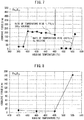
- FIG. 3 is a graph indicating the relationship between holding temperature and coercive force when an amorphous alloy having the composition B 86 B 13 Cu 1 was subjected to heat treatment.
- FIG. 4 is a graph indicating the relationship between holding temperature and coercive force when an amorphous alloy having the composition Fe 85 B 13 Nb 1 Cu 1 was subjected to heat treatment (rate of temperature rise: 415°C/sec, holding time: 0 sec).
- FIG. 5 is a graph indicating the relationship between holding time and coercive force when an amorphous alloy having the composition Fe 85 B 13 Nb 1 Cu 1 was subjected to heat treatment (rate of temperature rise: _415°C/sec, holding temperature: 500_°C).
- FIG. 4 is a graph indicating the relationship between holding temperature and coercive force when an amorphous alloy having the composition Fe 85 B 13 Nb 1 Cu 1 was subjected to heat treatment (rate of temperature rise: _415°C/sec, holding temperature: 500_°C
- FIG. 6 is a graph indicating the relationship between rate of temperature rise and coercive force when an amorphous alloy having the composition Fe 85 B 13 Nb 1 Cu 1 was subjected to heat treatment (holding temperature: 500°C, holding time: Varied 0 to 80_sec).
- FIG. 7 is a graph indicating the relationship between holding temperature and coercive force when an amorphous alloy having the composition Fe 87 B 13 was subjected to heat treatment.
- FIG. 8 is a graph indicating the relationship between holding temperature and coercive force when an amorphous alloy having the composition Fe 87 B 13 was subjected to heat treatment (rate of temperature rise: 485C/sec, holding time: varied 0 to 30 sec).
- FIG. 9 is a graph indicating the relationship between rate of temperature rise and coercive strength when an amorphous alloy having the composition Fe 87 B 13 was subjected to heat treatment (holding temperature: 485 °C, holding time: varied 0 to 30 sec).
- FIG. 10 is a graph showing the results of X-ray analysis of soft magnetic materials after having rapidly raised the temperature of amorphous alloys and held at that temperature for a short period of time (rate of temperature rise: 415 °C/sec, holding temperature: varied 485 to 570 °C, holding time: 0 to 30 sec).
- the average grain diameter was able to be confirmed to be 30 nm or less.
Landscapes
- Chemical & Material Sciences (AREA)
- Engineering & Computer Science (AREA)
- Organic Chemistry (AREA)
- Materials Engineering (AREA)
- Mechanical Engineering (AREA)
- Metallurgy (AREA)
- Physics & Mathematics (AREA)
- Dispersion Chemistry (AREA)
- Electromagnetism (AREA)
- Power Engineering (AREA)
- Thermal Sciences (AREA)
- Crystallography & Structural Chemistry (AREA)
- Soft Magnetic Materials (AREA)
Description
- The present invention relates to a method for producing a soft magnetic material. More particularly, the present invention relates to a method for producing a soft magnetic material having both high saturation magnetization and low coercive force.
- Soft magnetic materials used in the cores of components such as motors or reactors are required to demonstrate both high saturation magnetization and low coercive force in order to enhance the performance of these components.
- Soft magnetic materials having high saturation magnetization includes Fe-based nanocrystalline soft magnetic materials. Fe-based nanocrystalline soft magnetic materials refer to soft magnetic materials composed mainly of Fe in which nanocrystals are dispersed in the material at 30% by volume or more.
- For example,
Patent Document 1 discloses an Fe-based nanocrystalline soft magnetic material represented by the compositional formula Fe100-p-q-r-sCupBqSirSns (wherein, p, q, r and s are in atomic percent (at%) and satisfy the relational expressions of 0.6≤p≤1.6, 6≤q≤20, 0<r≤17 and 0.005≤s≤24). - In addition,
Patent Document 1 discloses that an Fe-based nanocrystalline soft magnetic material is obtained by heat-treating a thin ribbon having a composition represented by Fe100-p-q-r-sCupBqSirSns and amorphous phase. - [Patent Document 1] Japanese Unexamined Patent Publication No.
2014-240516 - Fe-based nanocrystalline soft magnetic materials have high saturation magnetization since they have Fe as a main component thereof. Fe-based nanocrystalline soft magnetic materials are obtained by heat-treating (it is also referred to "annealing"; the same shall apply hereinafter) a ribbon having an amorphous phase. If the Fe content in the amorphous ribbon is high, a crystalline phase (α-Fe) is easily formed from the amorphous phase and the crystalline phase easily becomes coarse as a result of undergoing grain growth. Therefore, the addition of an element that inhibits grain growth in the material reduces the Fe content in the material corresponding to the amount of that element added, thereby lowering saturation magnetization.
- On the basis of the above, the inventors of the present invention found the problem in which, although high saturation magnetization is obtained when the main component of a soft magnetic material is Fe, since a crystalline phase forms from the amorphous phase during heat treatment and that crystalline phase becomes coarse as a result of grain growth, it is difficult to obtain low coercive force.
- In order to solve the aforementioned problem, an object of the present invention is to provide a method for producing a soft magnetic material having both high saturation magnetization and low coercive force.
- The inventors of the present invention make extensive studies to solve the aforementioned problem, thereby leading to completion of the present invention. The gist thereof is as indicated below.
- (1) A method for producing a soft magnetic material, comprising:
- preparing a alloy having a composition represented by the following
Compositional Formula 1 orCompositional Formula 2 and having an amorphous phase, and - heating the alloy at a rate of temperature rise of 10°C/sec or more, and holding for 0 to 80 seconds at a temperature equal to or higher than the crystallization starting temperature and lower than the temperature at which Fe-B compounds start to form; wherein,
- the
Compositional Formula 1 is Fe100-x-yBxMy, M represents at least one element selected from Nb, Mo, Ta, W, Ni, Co and Sn, and x and y are in atomic percent (at%) and satisfy the relational expressions of 10≤x≤16 and 0≤y≤8, and - the
Compositional Formula 2 is Fe100-a-b-cBaCubM'c, M' represents at least one element selected from Nb, Mo, Ta, W, Ni and Co, and a, b and c are in atomic percent (at%) and satisfy therelational expressions 10≤a≤16, 0<b≤2 and 0≤c≤8.
- preparing a alloy having a composition represented by the following
- (2) The method described in (1), wherein the alloy is obtained by quenching a melt.
- (3) The method described in (1) or (2), wherein the rate of temperature rise is 125°C/sec or more.
- (4) The method described in (1) or (2), wherein the rate of temperature rise is 415°C/sec or more
- (5) The method described in any one of (1) to (4), wherein the alloy is held for 0 seconds to 17 seconds at the temperature equal to or higher than the crystallization starting temperature and lower than the temperature at which Fe-B compounds start to form.
- (6) The method described in any one of (1) to (5), comprising:
clamping the alloy between heated blocks and heating the alloy. - According to the present invention, even if the main component of a alloy having an amorphous phase is Fe in order to obtain high saturation magnetization, by rapidly raising the temperature of that alloy to a temperature equal to or higher than the crystallization starting temperature and lower than the temperature at which Fe-B compounds start to form and then cooling immediately, or holding for a short period of time at that temperature, the crystalline phase becomes increasingly fine allowing the obtaining of low coercive force. In other words, according to the present invention, a method can be provided for producing a soft magnetic material having both high saturation magnetization and low coercive force.
-
-
FIG. 1 is a perspective view showing an overview of an apparatus of clamping the alloy between heated blocks in order to heat the alloy. -
FIG. 2 is a graph indicating the relationship between heating time and temperature of an amorphous alloy when heating the amorphous alloy. -
FIG. 3 is a graph indicating the relationship between holding temperature and coercive force when an amorphous alloy having the composition B86B13Cu1 was subjected to heat treatment. -
FIG. 4 is a graph indicating the relationship between holding temperature and coercive force when an amorphous alloy having the composition Fe85B13Nb1Cu1 was subjected to heat treatment (rate of temperature rise: 415 °C/sec, holding time: 0 sec). -
FIG. 5 is a graph indicating the relationship between holding time and coercive force when an amorphous alloy having the composition Fe85B13Nb1Cu1 was subjected to heat treatment (rate of temperature rise: 415 °C/sec, holding temperature: 500 °C). -
FIG. 6 is a graph indicating the relationship between rate of temperature rise and coercive force when an amorphous alloy having the composition Fe85B13Nb1Cu1 was subjected to heat treatment (holding temperature: 500 °C, holding time: varied from 0 to 80 sec). -
FIG. 7 is a graph indicating the relationship between holding temperature and coercive force when an amorphous alloy having the composition Fe87B13 was subjected to heat treatment. -
FIG. 8 is a graph indicating the relationship between holding temperature and coercive force when an amorphous alloy having the composition Fe87B13 was subjected to heat treatment (rate of temperature rise: 415 °C/sec, holding time: 0 sec). -
FIG. 9 is a graph indicating the relationship between rate of temperature rise and coercive strength when an amorphous alloy having the composition Fe87B13 was subjected to heat treatment (holding temperature: 485 °C, holding time: Varied from 0 to 30 sec). -
FIG. 10 is a graph showing the results of X-ray analysis of soft magnetic materials after having rapidly raised the temperature of amorphous alloys and held at that temperature for a short period of time (rate of temperature rise: 415 °C/sec, holding temperature: varied between 485°C and 570 °C, holding time: 0 sec). - The following provides a detailed explanation of embodiments of the method for producing a soft magnetic material according to the present invention. Furthermore, the present invention is not limited to the embodiments indicated below.
- In order to obtain both high saturation magnetization and low coercive force, a alloy having Fe as the main component thereof and an amorphous phase is rapidly raised to a temperature equal to or higher than the crystallization starting temperature and lower than the temperature at which Fe-B compounds start to form, and then holding at that temperature for a short period of time.
- In the present description, "having Fe as the main component thereof" refers to the content of Fe in the material being 50 at% or more. A "alloy having an amorphous phase" refers to a alloy containing 50% by volume or more of an amorphous phase in that alloy, and this may also be simply referred to as an "amorphous alloy". The "alloy" has such forms as ribbon, flake, granules, and bulk and the like.
- Although not bound by theory, the following phenomenon is thought to occur in the amorphous alloy when the amorphous alloy is subjected to heat treatment at a temperature equal to or higher than the crystallization starting temperature and lower than the temperature at which Fe-B compounds start to form.
- A crystalline phase is formed from the amorphous phase when the amorphous alloy is raise in temperature to a temperature equal to or higher than the crystallization starting temperature. The phenomenon that occurs during the process thereof is explained by dividing into the case in which elements serving as heterogeneous nucleation sites are present in the amorphous alloy, and the case in which such elements are not present in the amorphous alloy. Furthermore, in the present description, elements that serve as heterogeneous nucleation sites are elements that do not readily form a solid solution with Fe.
- An example of an element that serves as a heterogeneous nucleation site and that is not soluble in Fe is Cu. When the amorphous alloy contains Cu, Cu becomes a nucleation site, heterogeneous nucleation occurs at these Cu clusters as a starting point, and the crystalline phase is refined. When the amorphous alloy contains Cu, adequate nucleation occurs even in the case of raising the temperature of the amorphous alloy at a low rate (about 1.7°C/sec), and a fine crystalline phase is thought to be obtained.
- On the other hand, when an element serving as a heterogeneous nucleation site, such as Cu, is not present in the amorphous alloy, the coarsening of the microstructure is thought to be avoided and a fine crystalline phase is thought to be obtained by rapidly raising the temperature of the amorphous alloy (10°C/sec or more) and cooling immediately or holding at that temperature for a short period of time (0 seconds to 80 seconds). The details thereof are as indicated below. Furthermore, the holding time being 0 second means immediately cooling or stopping holding after rapidly raising the temperature.
- The homogeneous nucleation rate is governed by the atomic transport and the critical nucleus size. A high atomic transport and a small critical nucleus size result in a high homogeneous nucleation rate, leading to a finer microstructure. To realize these two conditions, it is effective to induce a supercooled liquid region in the amorphous solid. This is because the viscous flow in supercooled liquid is massive and the strain energy due to nucleation in a supercooled liquid is considerably smaller than that in amorphous solids. Hence, a higher number of embryos becomes nuclei when supercooled liquid regions are realized. However, the conventional annealing results in crystallization of the amorphous solid in relatively low temperatures where the transition from solid to supercooled liquid is limited. Thus, the homogeneous nucleation under conventional heating rates is very limited. Contrarily, the crystallization onset temperature is raised by rapid heating. Hence, a high homogeneous nucleation rate is realized because the amorphous phase is retained at higher temperatures where the transition of the amorphous solid to a supercooled liquid takes place vigorously. As a result, nucleation frequency becomes higher.
- The temperature of an amorphous alloy is rapidly raised (10°C/ sec or more) to the crystallization starting temperature or higher in order to allow atomic transport to occur resulting in vigorous nucleation in a region formed in a supercooled state as mentioned above. Since the rate of grain growth also increases when the temperature of the amorphous alloy is raised rapidly, the duration of grain growth is shortened by shorting holding time (0 seconds to 80 seconds). From the viewpoint of atomic transport, the temperature of the amorphous alloy is preferably raised to a temperature that is as high as possible beyond the crystallization starting temperature thereof. However, if the temperature of the amorphous alloy reaches the temperature at which Fe-B compounds start to form, those Fe-B compounds are formed. Fe-B compounds increase coercive force due to their large magnetocrystalline anisotropy. Thus, the temperature of the amorphous alloy is preferably rapidly raised to a temperature that is equal to or higher than the crystallization starting temperature and lower than the temperature at which Fe-B compounds start to form.
- The temperature of the amorphous alloy is required to be rapidly raised to a temperature range that is equal to or higher than the crystallization starting temperature and lower than the temperature at which Fe-B compounds start to form. However, in the case of slowly raising the temperature of the amorphous alloy to a temperature range lower than the crystallization starting temperature, it is difficult to immediately switch over to rapidly raising the temperature when the temperature of the amorphous alloy has reached the crystallization starting temperature. In addition, there are no particular problems with rapidly raising the temperature of the amorphous alloy in a temperature range lower than the crystallization starting temperature. Thus, the temperature may be increased rapidly starting from when the temperature of the amorphous alloy is lower than the crystallization starting temperature, and the temperature may be continued to be raised rapidly after the amorphous alloy has reached the crystallization starting temperature.
- Rapidly raising the temperature as previously described is effective when an element serving as a heterogeneous nucleation site is not present in the amorphous alloy. When an element, such as Cu, serving as a heterogeneous nucleation site is present in the amorphous alloy, it becomes possible to cumulatively obtain the effect of refining crystal grain sizes as a result of Cu serving as a nucleation site, and the effect of refining crystal grains due to remarkable increase of nucleation frequency by rising temperature rapidly.
- On the basis of the phenomena explained so far, the inventors of the present invention found that, in order to obtain both high saturation magnetization and low coercive force, an amorphous alloy should be subjected to heat treatment comprising rapidly raising the temperature thereof to a temperature equal to or higher than the crystallization starting temperature and lower than the temperature at which Fe-B compounds start to form followed by immediate cooling or holding at that attained temperature for a short period of time. This heat treatment was found to be effective regardless of whether or not an element serving as a heterogeneous nucleation site, such as Cu, is present in the amorphous alloy.
- The following provides an explanation of the configuration of the method for producing a soft magnetic material according to the present invention based on these findings.
- A alloy having an amorphous phase (amorphous alloy) is prepared. As previously described, the amorphous phase accounts for 50% by volume or more of the amorphous alloy. From the viewpoint of rapidly raising the temperature of the amorphous alloy and holding at that temperature to obtain more of a fine crystalline phase, the content of the amorphous phase in the amorphous alloy is preferably 60% by volume or more, 70% by volume or more or 90% by volume or more.
- The amorphous alloy has a composition represented by
Compositional Formula 1 orCompositional Formula 2. An amorphous alloy having a composition represented by Compositional Formula 1 (hereinafter, referred to "amorphous alloy ofCompositional Formula 1") does not contain an element that serves as a heterogeneous nucleation site. An amorphous alloy having a composition represented by Compositional Formula 2 (hereinafter, referred to "amorphous alloy ofCompositional Formula 2") contains an element that serves as a heterogeneous nucleation site. -
Compositional Formula 1 is Fe100-x-yBxMy.In Compositional Formula 1, M represents at least one element selected from Nb, Mo, Ta, W, Ni, Co and Sn, and x and y satisfy the relational expressions of 10≤x≤16 and 0≤y≤8. x and y are in atomic percent (at%), x represents the content of B, and y represents the content of M. - The amorphous alloy of
Compositional Formula 1 has Fe for the main component thereof, and the Fe content thereof is 50 at% or more. The content of Fe is represented as the remainder of B and M. From the viewpoint of a soft magnetic material, obtained by rapidly raising the temperature of an amorphous alloy and holding at that temperature, having high saturation magnetization, Fe content is preferably 80 at% or more, 84 at% or more or 88 at% or more. - The amorphous alloy is obtained by quenching a melt having Fe as the main component thereof. B (Boron) promotes the formation of an amorphous phase when the melt is quenched. The main phase of the amorphous alloy becomes an amorphous phase if the content of B in an amorphous alloy obtained by quenching the melt is 10 at% or more. As previously described, the main phase of the alloy being an amorphous phase means that the content of the amorphous phase in the alloy is 50% by volume or more. In order to make the main phase of the alloy to be an amorphous phase, the content of B in the amorphous alloy is preferably 11 at% or more and more preferably 12 at% or more. On the other hand, Fe-B compound formation upon crystallization of the amorphous phase can be avoided when the content of B in the amorphous alloy is 16 at% or less. From the view point of avoiding compound formation, the content of B in the amorphous alloy is preferably 15 at% or less and more preferably 14 at% or less.
- In addition to Fe and B, the amorphous alloy of
Compositional Formula 1 may also contain M as necessary. M is at least one element selected from Nb, Mo, Ta, W, Ni, Co and Sn. - In the case of selecting at least one element from Nb, Mo, Ta, W and Sn among M and an amorphous alloy contain the selected elements, when the temperature of the amorphous alloy is raised rapidly and held at that temperature, grain growth of the crystalline phase is inhibited and increases in coercive force are inhibited. In addition, the amorphous phase remaining in the alloy is stabilized even after having rapidly raised the temperature of the amorphous alloy and holding at that temperature. As a result of the occurrence of atomic transport in a region transitioned to a supercooled state when the temperature of the amorphous alloy is raised rapidly and held at that temperature, the inhibitory effect on the crystalline phase as a result of containing these elements is smaller in comparison with the effect of inhibiting grain growth of the crystalline phase due to the high nucleation frequency. As a result of the amorphous alloy containing these elements, the content of Fe in the amorphous alloy decreases resulting in a decrease saturation magnetization. Thus, the contents of these elements in the amorphous alloy are preferably the minimum required contents.
- The magnitude of induced magnetic anisotropy can be controlled when selecting at least one of Ni and Co among M and the amorphous alloy contains these elements. In addition, saturation magnetization can also be increased when the amorphous alloy contains Co.
- When the amorphous alloy contains M, the aforementioned action is provided corresponding to the content of M. In other words, Nb, Mo, Ta, W, Sn and P provide an action that inhibits grain growth of the crystalline phase and stabilizes the amorphous phase, while Ni and Co provide the action of controlling the magnitude of induced magnetic anisotropy and increasing saturation magnetization. From the viewpoint of enabling these actions to be provided clearly, the content of M is preferably 0.2 at% or more and more preferably 0.5 at% or more. On the other hand, when the content of M is 8 at% or less, the amounts of essential elements of Fe and B in the amorphous alloy do not become excessively low, and as a result, a soft magnetic material obtained by rapidly raising the temperature of the amorphous alloy and holding at that temperature is able to have both high saturation magnetization and low coercive force. Furthermore, in the case of having selected two or more elements for M, the content of M is the total content of these elements.
- The amorphous alloy of
Compositional Formula 1 may also contain unavoidable impurities such as S, O or N in addition to Fe, B and M. An unavoidable impurity refers to an impurity contained in the raw materials for which the containing thereof cannot be avoided, or an impurity that leads to a remarkable increase in production costs when attempted to be avoided. If such an avoidable impurity is contained, the purity of an alloy ofCompositional Formula 1 is preferably 97% by mass or more, more preferably 98% by mass or more and even more preferably 99% by mass or more. - Relating to
Compositional Formula 2, the following provides an explanation of those matters that differ from the case ofCompositional Formula 1. -
Compositional Formula 2 is Fe100-a-b-cBaCubM'c. InCompositional Formula 2, M' represents at least one element selected from Nb, Mo, Ta, W, Ni and Co, and a, b and c respectively satisfy therelational expressions 10≤a≤16, 0<b≤2 and 0≤c≤8. a, b and c are in in atomic percent (at%), a represents the content of B, b represents the content of Cu, and c represents the content of M'. - The amorphous alloy of
Compositional Formula 2 has Cu for an essential component thereof in addition to Fe and B. In addition to Fe, B and Cu, the amorphous alloy ofCompositional Formula 2 may also contain M' as necessary. M' is at least one element selected from Nb, Mo, Ta, W, Ni and Co. - When the amorphous alloy contains Cu, the Cu becomes a nucleation site during the temperature of amorphous alloy being raised rapidly and held at that temperature, heterogeneous nucleation occurs with its starting point in Cu clusters, and the crystalline phase grains becomes fine. Even if the content of Cu in the amorphous alloy is extremely low, the effect of grain refinement of the crystalline phase is comparatively large. In order to make this effect clearer, the content of Cu in the amorphous alloy is preferably 0.2 at% or more and more preferably 0.5 at% or more. On the other hand, when the Cu content in the amorphous alloy is 2 at% or less an amorphous alloy can be produced by rapid quenching of the melt without the formation of a crystalline phase. From the viewpoint of embrittlement of the amorphous alloy, the Cu content in the amorphous alloy is preferably 1 at% or less and more preferably 0.7 at% or less.
- The amorphous alloy of
Compositional Formula 2 may also contain unavoidable impurities such as S, O and N in addition to Fe, B, Cu and M'. An unavoidable impurity refers to an impurity contained in the raw materials for which the containing thereof cannot be avoided, or an impurity that leads to a remarkable increase in production costs when attempted to be avoided. The purity of the amorphous alloy ofCompositional Formula 2 when such an avoidable impurity is contained is preferably 97% by mass or more, more preferably 98% by mass or more and even more preferably 99% by mass or more. - The amorphous alloy is heated at a rate of temperature rise of 10°C/sec or more and is held for 0 to 80 seconds at a temperature equal to or higher than the crystallization starting temperature and lower than the temperature at which Fe-B compounds start to form.
- The crystalline phase does not become coarse when the rate of temperature rise is 10°C/sec or more. Since a higher rate of temperature rise is preferable from the viewpoint of avoiding increased coarseness of the crystalline phase, the rate of temperature rise may be 45°C/sec or more, 125°C/sec or more, or 150°C/sec or more, 415°C/sec or more. On the other hand, when the rate of temperature rise is extremely rapid, the heat source for heating becomes excessively large, thereby impairing economic feasibility. From the viewpoint of the heat source, the rate of temperature rise is preferably 415°C/sec or less. The rate of temperature rise may be an average rate from heating start to holding start. When the holding time is 0 sec, it may be an average rate from heating start to cooling start. Alternatively, it may be an average rate between certain temperature range, for example, the temperature range from 100°C to 400°C.
- When the holding time is 0 seconds or more, a fine crystalline phase can be obtained from the amorphous phase. Furthermore, the holding time being 0 second means immediately cooling or stopping holding after rapidly raising the temperature. On the other hand, when the holding time is 80 seconds or less, increased coarseness of the crystalline phase can be avoided. From the viewpoint of avoiding increased coarseness of the crystalline phase, the holding time is 60 seconds or less, 40 seconds or less, 20 seconds or less, or 14 seconds.
- The amorphous phase can be converted to a crystalline phase when the holding temperature is equal to or higher than the crystallization starting temperature. Holding temperature can be raised since the duration of holding is short. Holding temperature is suitably determined in consideration of the balance with holding time. On the other hand, strong magnetocrystalline anisotropy occurs due to the formation Fe-B compounds when the holding temperature exceeds the temperature at which Fe-B compounds start to form, and coercive force increases as a result thereof. Thus, by holding at the highest temperature that does not reach the temperature at which Fe-B compounds start to form, the crystalline phase can be refined without forming Fe-B compounds. The temperature of the amorphous alloy may be held at a temperature that is just lower than the temperature at which Fe-B compounds start to form in order to refine crystalline phase in this manner. A temperature just lower than the temperature at which Fe-B compounds start to form refers to a temperature that is 5°C or less lower than the temperature at which Fe-B compounds start to form, a temperature that is 10°C or less lower than the temperature at which Fe-B compounds start to form, or a temperature that is 20°C or less lower than the temperature at which Fe-B compounds start to form.
- There are no particular limitations on the heating method provided the amorphous alloy can be heated at the previously explained rate of temperature rise.
- When the amorphous alloy is heated using an ordinary atmosphere furnace, it is effective to make the rate of temperature rise of the oven atmosphere higher than the desired rate of temperature rise of the amorphous alloy. Similarly, it is effective to make the atmospheric temperature in the furnace to be higher than the desired holding temperature of the amorphous alloy. For example, when raising the temperature of the amorphous alloy at the rate of 150°C/sec and holding the amorphous alloy at 500°C, it is effective to raise the temperature of the atmosphere in the furnace at 170°C/sec and hold the temperature the atmosphere in the furnace at 520°C.
- A time-lag between the amount of heat supplied from an infrared heater and amount of heat received to the amorphous alloy can be reduced by using an infrared furnace. Furthermore, an infrared furnace refers to a furnace that rapidly heats a heated object by reflecting light emitted from an infrared lamp with a concave surface.
- Moreover, the temperature of the amorphous alloy may be rapidly raised and held using heat transfer between solids.
FIG. 1 is a perspective view showing an overview of an apparatus that rapidly raises the temperature of an amorphous alloy and holds the alloy at that temperature by clamping the amorphous alloy between blocks which have already been heated to the required holding temperature. - An amorphous alloy is positioned so that it can be clamped by the
blocks 2. Theblocks 2 are provided with a heating element (not shown).Temperature controllers 3 are coupled to the heating element. Theamorphous alloy 1 can be heated by clamping the preheated blocks onto the alloy so that heat transfer between solids can take place, in other words, between theamorphous alloy 1 and theblocks 2. There are no particular limitations on the material and so forth of theblocks 2 provided heat is efficiently transferred between theamorphous alloy 1 and theblocks 2. Examples of materials of theblocks 2 include metal, alloy and ceramics and the like. - When the temperature of the amorphous alloy is raised at a rate of 100°C or more, the amorphous alloy per se generates heat due to heat released during crystallization of the amorphous phase. When the temperature of the amorphous alloy is rapidly raised using an atmosphere furnace or infrared furnace and the like, it is difficult to control temperature in consideration of generation of heat by the amorphous alloy per se. Consequently, in the case of using an atmosphere furnace or infrared furnace and the like, the temperature of the amorphous alloy is often higher than the target temperature, thereby resulting in increased coarseness of the crystalline phase. In contrast, as shown in
FIG. 1 , as a result of clamping theamorphous alloy 1 between theheated blocks 2, it becomes easy to control temperature in consideration of generation of heat by the amorphous alloy per se when theamorphous alloy 1 is heated. Consequently, when the amorphous alloy is rapidly raised in temperature as shown inFIG. 1 , the temperature of the amorphous alloy does not exceed the target temperature and increased coarseness of the crystalline phase can be avoided. - In addition, when the temperature of the amorphous alloy is raised rapidly as shown in
FIG. 1 , since the temperature of the amorphous alloy can be precisely controlled, the amorphous alloy can be held at a temperature just below the temperature which Fe-B compounds start to form, and the crystalline phase can be made to be fine without forming Fe-B compounds. - Next, an explanation is provided of the method for producing the amorphous alloy. There are no particular limitations on the method used to produce the amorphous alloy provided an amorphous alloy having a composition represented by the
aforementioned Compositional Formula 1 orCompositional Formula 2 is obtained. As mentioned above, the alloy has such forms as ribbon, flake, granules, and bulk and the like. The method for producing amorphous alloy can be suitably selected in order to obtain desired forms. - A method for producing the amorphous alloy includes a method comprising preparing in advance an ingot in which the amorphous alloy is provided so as to have a composition represented by
Compositional Formula 1 orCompositional Formula 2, and quenching a melt obtained by melting this ingot to obtain an amorphous alloy. When there is wastage of elements when melting the ingot, an ingot is prepared having a composition that anticipates that wastage. In addition, when melting the ingot after crushing, the ingot is preferably subjected to homogenization heat treatment prior to crushing. - The method of quenching the melt may be an ordinary method, and an example thereof includes a single roll method that uses a cooling roll made of copper or a copper alloy and the like. The peripheral velocity of the cooling roll in a single roll method may be the standard peripheral velocity when producing an amorphous alloy including Fe as the main component thereof. The peripheral velocity of the cooling roll is, for example, 15 m/sec or more, 30 m/sec or more or 40 m/sec or more and 55 m/sec or less, 70 m/sec or less or 80 m/sec or less.
- The temperature of the melt when discharging the melt to the single roll is preferably 50°C to 300°C higher than the melting point of the ingot. Although there are no particular limitations on the atmosphere when discharging the melt, the atmosphere is preferably that of an inert gas and the like from the viewpoint of reducing contamination of the amorphous alloy by oxides and the like.
- The following provides a more detailed explanation of the present invention through examples thereof. Furthermore, the present invention is not limited to these examples.
- Raw materials were weighed out so as to have the prescribed composition, and after arc melting the raw materials, the melt was cast in a mold to prepare an ingot. High purity Fe powder, Fe-B alloy and pure Cu powder were used for the raw materials.
- The crushed ingot is charged into the nozzle of a liquid rapid cooling apparatus (single roll method) and then melted by high-frequency induction heating to obtain a melt. The melt is then discharged onto a copper roll having a peripheral velocity of 40 m/s to 70 m/s to obtain an amorphous alloy having a width of 1 mm or more. Furthermore, the amorphous alloy was subjected to X-ray diffraction (XRD) analysis prior to the heat treatment to be subsequently described. In addition, the crystallization starting temperature, the temperature at which Fe-B compounds start to form and the curie temperature of the amorphous phase were measured. Differential thermal analysis (DTA) and thermo-magneto-gravimetric analysis (TMGA) were used for these measurements.
- As shown in
FIG. 1 , the amorphous alloy was clamped between heated blocks followed by heating the amorphous alloy for a certain amount of time. As a result of this heating, the amorphous phase in the amorphous alloy was crystallized for use as a sample of a soft magnetic material. Furthermore, the rate of temperature rise was based off the temperature range between 100°C to 400°C as shown inFIG. 2 . - Heat-treated samples were evaluated in the manner described below. Saturation magnetization was measured using a vibrating sample magnetometer (VSM) (maximum applied magnetic field: 10 kOe). Coercive force was measured using a direct current BH analyzer. The crystalline phase was identified by XRD analysis.
- Evaluation results are shown in Table 1. Table 1 indicates the compositions of the amorphous alloys, heating conditions, crystallization starting temperatures, temperatures at which Fe-B compounds start to form, and curie temperatures of the amorphous phase.
-
Table 1 (Part 1) Composition Holding temperature Tc Rate of temperature rise Holding time Atmosphere Coercive' force Hc Saturation magnetization Js Crystallization starting temperature Tx1 Starting temperature of Fe-B compound formation Tx2 Tx2-Tx1 Amorphous phase curie temperature Tc °C °C/sec sec A/m T °C °C °C °C Example 1 Fe83B12Nb4Cu1 552 415 17 Air 5.0 1.63 414 647 233 142 Example 2 Fe83B13Nb3Cu1 552 415 17 Air 7.0 1.68 409 583 174 187 Example 3 Fe84B12Nb3Cu1 552 415 17 Air 5.0 1.69 395 586 191 165 Example 4 Fe83B14Nb2Cu1 533 415 17 Air 6.0 1.71 404 549 145 234 Example 5 Fe84B13Nb2Cu1 524 415 17 Air 7.0 1.74 390 546 156 213 Example 6 Fe85B12Nb2Cu1 533 415 17 Air 13.0 1.80 356 548 192 186 Example 7 Fe84B14Nb1Cu1 495 415 17 Air 6.8 1.75 393 516 123 261 Example 8 Fe85B13Nb1Cu1 484 415 17 Air 4.4 1.81 378 517 139 238 Example 9 Fe86B12Nb1Cu1 486 415 17 Air 19.0 1.87 346 516 170 214 Example 10 Fe86B13Cu1 467 415 17 Air 10.2 1.88 365 483 118 269 Example 11 Fe87B12Cu1 472 415 0 Ar 12.1 1.89 342 486 144 247 Example 12 Fe87B13 472 415 0 Ar 8.8 1.87 382 488 106 247 Example 13 Fe86.8B13Cu0.2 472 415 0 Ar 6.9 1.89 380 489 109 260 Example 14 Fe86.5B13Cu0.5 472 415 0 Ar 6.1 1.89 375 484 109 262 Example 15 Fe86B13Cu1 472 415 0 Ar 5.1 1.88 365 482 117 265 -
Table 1 (Part 2) Composition Holding temperature Tc Rate of temperature rise Holding time Atmosphere' Coercive force Hc Saturation magnetization Js Crystallization starting temperature Tx1 Starting temperature of Fe-B compound formation Tx2 Tx2-Tx1 Amorphous phase curie temperature Tc °C °C/sec sec A/m T °C °C °C °C Example 16 Fe85.5B13Cu1.5 472 415 0 Ar 3.3 1.88 356 481 125 282 Example 17 Fe85B14Cu1 472 415 0 Ar 5.5 1.88 387 489 102 273 Example 18 Fe84B15Cu1 472 415 0 Ar 5.7 1.88 397 489 92 302 Example 19 Fe83B12Nb4Cu1 552 415 0 Ar 1.5 1.63 414 647 233 142 Example 20 Fe83B13Nb3Cu1 552 415 0 Ar 1.7 1.69 409 583 174 187 Example 21 Fe84B12Nb3Cu1 552 415 0 Ar 2.0 1.70 395 586 191 165 Example 22 Fe83B14Nb2Cu1 533 415 0 Ar 1.4 1.70 404 549 145 234 Example 23 Fe84B13Nb2Cu1 524 415 0 Ar 2.4 1.75 390 546 156 213 Example 24 Fe85B12Nb2Cu1 533 415 0 Ar 10.5 1.79 356 548 192 186 Example 25 Fe84B14Nb2Cu1 495 415 0 Ar 2.8 1.75 393 516 123 261 Example 26 Fe85B13Nb1Cu1 486 415 0 Ar 2.5 1.80 378 517 139 238 Example 27 Fe86B12Nb1Cu1 486 415 0 Ar 17.0 1.73 346 516 170 214 Example 28 Fe85.8B13Nb0.2Cu1 467 415 0 Ar 4.0 1.82 362 489 127 248 Example 29 Fe85.5B12Nb0.5Cu1 477 415 0 Ar 4.0 1.83 365 499 134 244 Example 30 Fe85.3B13Nb0.7Cu1 477 415 0 Ar 5.2 1.81 399 506 107 240 -
Table 1 (Part 3) Composition Holding temperature Tc Rate of temperature rise Holding time Atmosphere Coercive force Hc Saturation magnetization Js Crystallization starting temperature Tx1 Starting temperature of Fe-B compound formation Tx2 Tx2-Tx1 Amorphous phase curie temperature Tc °C °C/sec sec A/m T °C °C °C °C Example 31 Fe86B13Nb1 495 415 0 Ar 5.7 1.89 379 526 147 211 Example 32 Fe84B13Nb3 533 415 0 Ar 7.2 1.75 420 569 149 166 Example 33 Fe86B13Nb1 495 415 0 Ar 6.8 1.80 381 509 128 207 Example 34 Fe86.5B13Mo0.5Cu1 495 415 0 Ar 10.8 1.83 368 492 124 240 Example 35 Fe85B13Mo1Cu1 495 415 0 Ar 9.8 1.85 374 495 121 242 Example 36 Fe84B13Mo2Cu1 495 415 0 Ar 2.9 1.70 386 425 138 189 Example 37 Fe86B13Ta1 514 415 0 Ar 6.4 1.83 391 532 141 210 Example 38 Fe85B13Ta1Cu1 505 415 0 Ar 5.2 1.75 377 529 152 224 Example 39 Fe84B 13Ta2Cu1 505 415 0 Ar 5.5 1.77 387 553 166 208 Example 40 Fe86B13W1 486 415 0 Ar 8.5 1.89 382 508 126 207 Example 41 Fe85B13W1Cu1 486 415 0 Ar 2.1 1.85 380 506 126 225 Example 42 Fe86.5B12Ni1Cu0.5 472 415 0 Ar 5.5 1.90 379 489 110 279 Example 43 Fe86B13Ni1 467 415 0 Ar 8.7 1.94 355 489 134 252 Example 44 Fe84B13Ni3 467 415 0 Ar 5.9 1.93 356 485 129 295 Example 45 Fe80B13Ni7 467 415 0 Ar 4.1 1.85 352 484 132 353 -
Table 1 (Part 4) Composition Holding temperature Tc Rate of temperature rise Holding time Atmosphere Coercive force Hc Saturation magnetization Js Crystallization starting temperature Tx1 Starting temperature of Fe-B compound formation Tx2 Tx2-Tx1 Amorphous phase curie temperature Tc °C °C/sec sec A/m T °C °C °C °C Example 46 Fe85.5B13Ni1Cu0.5 472 415 0 Ar 5.1 1.89 369 483 114 284 Example 47 Fe85B13Ni1Cu1 472 415 0 Ar 2.5 1.91 369 483 114 287 Example 48 Fe83.5B13Ni3Cu0.5 472 415 0 Ar 2.6 1.90 375 482 107 313 Example 49 Fe84.5B14Ni3Cu0.5 472 415 0 Ar 9.6 1.89 380 489 109 285 Example 50 Fe83.5B15Ni3Cu0.5 472 415 0 Ar 12.1 1.85 403 488 85 311 Example 51 Fe85.5Co1B13Cu0.5 477 415 0 Ar 4.9 1.91 371 487 116 285 Example 52 Fe85Co1B13Cu1 477 415 0 Ar 4.3 1.90 374 487 113 295 Example 53 Fe87B12Nb1 514 415 0 Ar 11.5 1.89 360 526 166 148 Example 54 Fe86B12Nb2 552 415 0 Ar 7.8 1.83 382 560 178 164 Example 55 Fe85B12Nb3 561 415 0 Ar 5.8 1.75 400 574 174 139 Example 56 Fe84B12Nb4 580 415 0 Ar 6.5 1.68 428 593 165 122 Example 57 Fe85B13Nb2 533 415 0 Ar 6.2 1.75 401 559 158 184 Example 58 Fe83B13Nb4 590 415 0 Ar 9.8 1.68 439 591 152 138 Example 59 Fe82B13Nb5 609 415 0 Ar 10.7 1.56 474 604 130 111 Example 60 Fe85B14Nb1 514 415 0 Ar 5.8 1.84 403 522 130 239 -
Table 1 (Part 5) Composition Holding temperature Tc Rate of temperature rise Holding time Atmosphere Coercive force Hc Saturation magnetization Js Crystallization starting temperature Tx1 Starting temperature of Fe-B compound formation Tx2 Tx2-Tx1 Amorphous phase curie temperature Tc °C °C/sec sec A/m T °C °C °C °C Example 61 Fe84B14Nb2 524 415 0 Ar 5.4 1.77 415 550 130 210 Example 62 Fe85B15 439 415 0 Ar 16.2 1.85 416 464 48 285 Example 63 Fe84B15Sn1 467 415 0 Ar 30.1 1.83 421 493 72 305 Example 64 Fe82B15Sn3 467 415 0 Ar 17.1 1.83 431 498 67 352 Comp. Ex. 1 Fe86B13Cu1 460 1.7 300 Vacuum 79.3 1.88 365 483 118 269 - The evaluation results were summarized indicated below in
FIGS. 3 to 9 . -
FIG. 3 is a graph indicating the relationship between holding temperature and coercive force when an amorphous alloy having the composition B86B13Cu1 was subjected to heat treatment.FIG. 4 is a graph indicating the relationship between holding temperature and coercive force when an amorphous alloy having the composition Fe85B13Nb1Cu1 was subjected to heat treatment (rate of temperature rise: 415°C/sec, holding time: 0 sec).FIG. 5 is a graph indicating the relationship between holding time and coercive force when an amorphous alloy having the composition Fe85B13Nb1Cu1 was subjected to heat treatment (rate of temperature rise: _415°C/sec, holding temperature: 500_°C).FIG. 6 is a graph indicating the relationship between rate of temperature rise and coercive force when an amorphous alloy having the composition Fe85B13Nb1Cu1 was subjected to heat treatment (holding temperature: 500°C, holding time: Varied 0 to 80_sec). -
FIG. 7 is a graph indicating the relationship between holding temperature and coercive force when an amorphous alloy having the composition Fe87B13 was subjected to heat treatment.FIG. 8 is a graph indicating the relationship between holding temperature and coercive force when an amorphous alloy having the composition Fe87B13 was subjected to heat treatment (rate of temperature rise: 485C/sec, holding time: varied 0 to 30 sec).FIG. 9 is a graph indicating the relationship between rate of temperature rise and coercive strength when an amorphous alloy having the composition Fe87B13 was subjected to heat treatment (holding temperature: 485 °C, holding time: varied 0 to 30 sec). -
FIG. 10 is a graph showing the results of X-ray analysis of soft magnetic materials after having rapidly raised the temperature of amorphous alloys and held at that temperature for a short period of time (rate of temperature rise: 415 °C/sec, holding temperature: varied 485 to 570 °C, holding time: 0 to 30 sec). - As can be understood from
FIG. 3 , coercive force was able to be confirmed to decrease when a temperature of an amorphous alloy having the composition Fe86B13Cu1 was rapidly raised in and held at that temperature for a short period of time. - As can be understood from
FIG. 4 , coercive force was able to be confirmed to increase if holding temperature exceeds the temperature at which Fe-B compounds start to form (517°C) when a temperature of an amorphous alloy having the composition Fe85B13Nb1Cu1 was rapidly raised and held at that temperature for a short period of time. - As can be understood from
FIG. 5 , although coercive force increased gradually as a result of increasing holding time, coercive force was able to be confirmed to be maintained at 10 A/m or less if holding time is 80 seconds or less when a temperature of an amorphous alloy having the composition Fe85B13Nb1Cu1 was rapidly raised and held at that temperature for a short period of time. - As can be understood from
FIG. 6 , coercive force was able to be confirmed to decrease due to an increase in rate of temperature rise when a temperature of an amorphous alloy having the composition Fe85B13Nb1Cu1 was rapidly raised and held at that temperature for a short period of time. - As can be understood from
FIG. 7 , coercive force was able to be confirmed to decrease when a temperature of an amorphous alloy having the composition Fe87B13 was rapidly raised and held at that temperature for a short period of time. In addition, at a holding temperature of less than 400°C, the amorphous phase did not crystallize and desired saturation magnetization is thought to be unable to be obtained even if held at that temperature for 300 seconds. - As can be understood from
FIG. 8 , coercive force was able to be confirmed to increase if holding temperature exceeds the temperature at which Fe-B compounds start to form (488°C) when a temperature of an amorphous alloy having the composition Fe87B13 was rapidly raised and held at that temperature for a short period of time. - As can be understood from
FIG. 9 , coercive force was able to be confirmed to decrease due to an increase in the rate of temperature rise when a temperature of an amorphous alloy having the composition Fe85B13Nb1Cu1 was rapidly raised and held at that temperature for a short period of time. - In addition, as can be understood from Table 1, when rapidly raised the temperature of an amorphous alloy and held at that temperature for a short period of time (Examples 1 to 65), low coercive force was able to be confirmed to be obtained while maintaining high saturation magnetization. On the other hand, when slowly raising the temperature of an amorphous alloy and holding at that temperature for a long period of time (Comparative Example 1), although high saturation magnetization was obtained, coercive force was able to be confirmed to increase.
- Furthermore, the reason for the existence of examples in which coercive force does not increase despite the holding temperature being higher than the temperature at which Fe-B compounds start to form is thought to be as indicated below. The temperatures at which Fe-B compounds start to form indicated in Table 1 were measured by differential thermal analysis. The rate at which the temperature of samples is raised in differential thermal analysis is extremely slow. In general, the temperature at which a compound starts to form is affected by the rate at which temperature is raised. Thus, the temperature at which Fe-B compounds start to form as measured by differential thermal analysis is thought to be lower than the temperature at which Fe-B compounds start to form when the temperature of the amorphous alloy is raised rapidly. This is also supported by the finding that peaks corresponding to Fe-B compounds are not observed in X-ray diffraction analysis for the samples of all of the examples as shown in
FIG. 10 . - In addition, when average grain diameter is calculated from half width based on the X-ray diffraction chart of
FIG. 10 , the average grain diameter was able to be confirmed to be 30 nm or less. - The effects of the present invention were able to be confirmed on the basis of the above results.
-
- 1 Amorphous alloy
- 2 Block
- 3 Temperature controller
Claims (6)
- A method for producing a soft magnetic material, comprising:preparing a alloy having a composition represented by the following Compositional Formula 1 or Compositional Formula 2 and having an amorphous phase, andheating the alloy at a rate of temperature rise of 10°C/sec or more and holding for 0 to 80 seconds at a temperature equal to or higher than the crystallization starting temperature and lower than the temperature at which Fe-B compounds start to form; wherein,the Compositional Formula 1 is Fe100-x-yBxMy, M represents at least one element selected from Nb, Mo, Ta, W, Ni, Co and Sn, and x and y are in atomic percent (at%) and satisfy the relational expressions of 10≤x≤16 and 0≤y≤8, andthe Compositional Formula 2 is Fe100-a-b-cBaCubM'c, M' represents at least one element selected from Nb, Mo, Ta, W, Ni and Co, and a, b and c are in atomic percent (at%) and satisfy the relational expressions 10≤a≤16, 0<b≤2 and 0≤c≤8.
- The method according to claim 1, wherein the alloy is obtained by quenching a melt.
- The method according to claim 1 or 2, wherein the rate of temperature rise is 125°C/sec or more.
- The method according to claim 1 or 2, wherein the rate of temperature rise is 325°C/sec or more.
- The method according to any one of claims 1 to 4, wherein the alloy is held for 0 seconds to 17 seconds at the temperature equal to or higher than the crystallization starting temperature and lower than the temperature at which Fe-B compounds start to form.
- The method according to any one of claims 1 to 5, comprising:
clamping the alloy between heated blocks and heating the alloy.
Applications Claiming Priority (2)
| Application Number | Priority Date | Filing Date | Title |
|---|---|---|---|
| JP2016153914A JP6862711B2 (en) | 2016-08-04 | 2016-08-04 | Manufacturing method of soft magnetic material |
| PCT/JP2017/028128 WO2018025931A1 (en) | 2016-08-04 | 2017-08-02 | Method for producing soft magnetic material |
Publications (4)
| Publication Number | Publication Date |
|---|---|
| EP3496114A1 true EP3496114A1 (en) | 2019-06-12 |
| EP3496114A8 EP3496114A8 (en) | 2019-08-28 |
| EP3496114A4 EP3496114A4 (en) | 2020-01-08 |
| EP3496114B1 EP3496114B1 (en) | 2021-04-21 |
Family
ID=61073738
Family Applications (1)
| Application Number | Title | Priority Date | Filing Date |
|---|---|---|---|
| EP17837033.4A Active EP3496114B1 (en) | 2016-08-04 | 2017-08-02 | Method for producing soft magnetic material |
Country Status (6)
| Country | Link |
|---|---|
| US (1) | US11352677B2 (en) |
| EP (1) | EP3496114B1 (en) |
| JP (1) | JP6862711B2 (en) |
| CN (1) | CN109844873B (en) |
| AU (1) | AU2017305032A1 (en) |
| WO (1) | WO2018025931A1 (en) |
Families Citing this family (14)
| Publication number | Priority date | Publication date | Assignee | Title |
|---|---|---|---|---|
| JP6881269B2 (en) * | 2017-12-06 | 2021-06-02 | トヨタ自動車株式会社 | Manufacturing method of soft magnetic material |
| JP6501005B1 (en) * | 2018-01-30 | 2019-04-17 | Tdk株式会社 | Soft magnetic alloys and magnetic parts |
| JP7143635B2 (en) * | 2018-05-30 | 2022-09-29 | トヨタ自動車株式会社 | Soft magnetic material and its manufacturing method |
| JP7192511B2 (en) * | 2019-01-10 | 2022-12-20 | トヨタ自動車株式会社 | Manufacturing method of alloy ribbon |
| AU2020207135B2 (en) * | 2019-01-11 | 2025-11-13 | Kite Magnetics PTY LTD | Iron based alloy |
| JP7234809B2 (en) * | 2019-06-06 | 2023-03-08 | トヨタ自動車株式会社 | Method for manufacturing alloy strip |
| EP3842555B1 (en) | 2019-12-26 | 2024-02-14 | Proterial, Ltd. | Soft magnetic alloy and magnetic core |
| CN111809125A (en) * | 2020-07-22 | 2020-10-23 | 郑州大学 | A kind of high saturation magnetic induction intensity iron-cobalt-based soft magnetic amorphous alloy with good bending toughness and preparation method thereof |
| CN114823030A (en) | 2021-01-22 | 2022-07-29 | 日立金属株式会社 | Soft magnetic alloy, soft magnetic alloy ribbon, method for producing same, magnetic core, and component |
| CN113667797B (en) * | 2021-07-23 | 2023-06-13 | 中国科学院宁波材料技术与工程研究所 | A high saturation magnetic induction amorphous nanocrystalline material and its heat treatment device and method |
| JPWO2023032913A1 (en) * | 2021-08-30 | 2023-03-09 | ||
| US20250129447A1 (en) | 2022-03-30 | 2025-04-24 | Proterial, Ltd. | Methodfor manufacturing nanocrystal alloy ribbon, and method for manufacturing magnetic sheet |
| DE102024200486A1 (en) | 2024-01-19 | 2025-07-24 | Fraunhofer-Gesellschaft zur Förderung der angewandten Forschung eingetragener Verein | Method for producing a soft magnetic core |
| DE102024205035A1 (en) * | 2024-05-30 | 2025-12-04 | Fraunhofer-Gesellschaft zur Förderung der angewandten Forschung eingetragener Verein | Method and apparatus for the heat treatment of amorphous ribbons |
Family Cites Families (8)
| Publication number | Priority date | Publication date | Assignee | Title |
|---|---|---|---|---|
| JPS5934780B2 (en) * | 1977-12-16 | 1984-08-24 | 松下電器産業株式会社 | Heat treatment method for amorphous magnetic alloy thin plate |
| US6648994B2 (en) * | 2000-01-06 | 2003-11-18 | Hitachi Metals, Ltd. | Methods for producing iron-based amorphous alloy ribbon and nanocrystalline material |
| JP4433900B2 (en) | 2004-06-29 | 2010-03-17 | 日立金属株式会社 | Method for producing iron-based rare earth isotropic nanocomposite magnet |
| JP5316921B2 (en) * | 2007-03-16 | 2013-10-16 | 日立金属株式会社 | Fe-based soft magnetic alloy and magnetic component using the same |
| JP6191908B2 (en) | 2013-06-12 | 2017-09-06 | 日立金属株式会社 | Nanocrystalline soft magnetic alloy and magnetic component using the same |
| JP6283417B2 (en) * | 2014-07-03 | 2018-02-21 | 株式会社東北マグネットインスティテュート | Magnetic core manufacturing method |
| US11264156B2 (en) * | 2015-01-07 | 2022-03-01 | Metglas, Inc. | Magnetic core based on a nanocrystalline magnetic alloy |
| US11232901B2 (en) | 2015-07-03 | 2022-01-25 | Tohoku Magnet Institute Co., Ltd. | Method for producing laminated magnetic core |
-
2016
- 2016-08-04 JP JP2016153914A patent/JP6862711B2/en active Active
-
2017
- 2017-08-02 WO PCT/JP2017/028128 patent/WO2018025931A1/en not_active Ceased
- 2017-08-02 EP EP17837033.4A patent/EP3496114B1/en active Active
- 2017-08-02 US US16/323,228 patent/US11352677B2/en active Active
- 2017-08-02 AU AU2017305032A patent/AU2017305032A1/en not_active Abandoned
- 2017-08-02 CN CN201780048622.3A patent/CN109844873B/en active Active
Also Published As
| Publication number | Publication date |
|---|---|
| EP3496114A4 (en) | 2020-01-08 |
| CN109844873B (en) | 2021-11-30 |
| EP3496114B1 (en) | 2021-04-21 |
| US20190185950A1 (en) | 2019-06-20 |
| AU2017305032A1 (en) | 2019-03-14 |
| WO2018025931A1 (en) | 2018-02-08 |
| US11352677B2 (en) | 2022-06-07 |
| JP6862711B2 (en) | 2021-04-21 |
| JP2018022797A (en) | 2018-02-08 |
| CN109844873A (en) | 2019-06-04 |
| EP3496114A8 (en) | 2019-08-28 |
Similar Documents
| Publication | Publication Date | Title |
|---|---|---|
| EP3496114B1 (en) | Method for producing soft magnetic material | |
| EP2149616B1 (en) | Soft magnetic thin strip, process for production of the same, magnetic parts, and amorphous thin strip | |
| EP4036269B1 (en) | Fe-based amorphous alloy containing subnanometer-scale ordered clusters, preparation method therefor, and nanocrystalline alloy derivatives thereof | |
| EP3511957A2 (en) | Soft magnetic alloy and magnetic device | |
| JP6842824B2 (en) | Manufacturing method of metal soft magnetic alloy and magnetic core | |
| KR100673046B1 (en) | Nano composite magnet powder and manufacturing method of magnet | |
| CN110556224B (en) | Soft magnetic material and method for producing same | |
| JP2016094651A (en) | Soft magnetic alloy and magnetic part | |
| CN109880985B (en) | Manufacturing method of soft magnetic material | |
| TWI639706B (en) | Method of forming magnetic core | |
| CN116397128B (en) | Rare earth copper chromium alloy material and preparation method thereof | |
| CN112514009A (en) | Alloy, magnetic material, bonded magnet and method for producing same | |
| KR20170082468A (en) | Method for manufacturing Fe based soft magnetic alloy | |
| JP2012023190A (en) | Manufacturing method of anisotropic rare earth magnet | |
| KR101475133B1 (en) | Sb-Te ALLOY POWDER FOR SINTERING, PROCESS FOR PRODUCTION OF THE POWDER, AND SINTERED TARGET | |
| JP7861754B2 (en) | Soft magnetic material and method for manufacturing the same | |
| JP3723016B2 (en) | Fe-based soft magnetic alloy | |
| JP2006291234A (en) | Microcrystalline alloy ribbon | |
| JP2000144349A (en) | Iron base soft magnetic alloy | |
| JP2002057021A (en) | Soft magnetic material and magnetic core | |
| JP7819497B2 (en) | alloy | |
| US20250118470A1 (en) | Soft magnetic material and method for producing the same | |
| JP2007211301A (en) | Microcrystal alloy thin strip and magnetic core | |
| KR20260003350A (en) | Soft magnetic amorphous Fe-Co alloy with high saturation magnetization | |
| JP2003041353A (en) | Fe-BASED SOFT MAGNETIC ALLOY |
Legal Events
| Date | Code | Title | Description |
|---|---|---|---|
| STAA | Information on the status of an ep patent application or granted ep patent |
Free format text: STATUS: THE INTERNATIONAL PUBLICATION HAS BEEN MADE |
|
| PUAI | Public reference made under article 153(3) epc to a published international application that has entered the european phase |
Free format text: ORIGINAL CODE: 0009012 |
|
| STAA | Information on the status of an ep patent application or granted ep patent |
Free format text: STATUS: REQUEST FOR EXAMINATION WAS MADE |
|
| 17P | Request for examination filed |
Effective date: 20190207 |
|
| AK | Designated contracting states |
Kind code of ref document: A1 Designated state(s): AL AT BE BG CH CY CZ DE DK EE ES FI FR GB GR HR HU IE IS IT LI LT LU LV MC MK MT NL NO PL PT RO RS SE SI SK SM TR |
|
| AX | Request for extension of the european patent |
Extension state: BA ME |
|
| RAP1 | Party data changed (applicant data changed or rights of an application transferred) |
Owner name: MONASH UNIVERSITY Owner name: TOYOTA JIDOSHA KABUSHIKI KAISHA |
|
| RIN1 | Information on inventor provided before grant (corrected) |
Inventor name: PARSONS, RICHARD Inventor name: ONODERA, KIYOTAKA Inventor name: ZANG, BOWEN Inventor name: SUZUKI, KIYONORI |
|
| RAP1 | Party data changed (applicant data changed or rights of an application transferred) |
Owner name: TOYOTA JIDOSHA KABUSHIKI KAISHA Owner name: MONASH UNIVERSITY |
|
| DAV | Request for validation of the european patent (deleted) | ||
| DAX | Request for extension of the european patent (deleted) | ||
| A4 | Supplementary search report drawn up and despatched |
Effective date: 20191211 |
|
| RIC1 | Information provided on ipc code assigned before grant |
Ipc: C22C 38/16 20060101ALI20191205BHEP Ipc: C22C 38/12 20060101ALI20191205BHEP Ipc: C21D 6/00 20060101ALI20191205BHEP Ipc: C22C 38/00 20060101ALI20191205BHEP Ipc: C22C 38/10 20060101ALI20191205BHEP Ipc: C22C 38/08 20060101ALI20191205BHEP Ipc: C22C 33/00 20060101ALI20191205BHEP Ipc: H01F 1/153 20060101AFI20191205BHEP Ipc: C22C 45/02 20060101ALI20191205BHEP |
|
| GRAP | Despatch of communication of intention to grant a patent |
Free format text: ORIGINAL CODE: EPIDOSNIGR1 |
|
| STAA | Information on the status of an ep patent application or granted ep patent |
Free format text: STATUS: GRANT OF PATENT IS INTENDED |
|
| RIC1 | Information provided on ipc code assigned before grant |
Ipc: C22C 38/12 20060101ALI20201007BHEP Ipc: C22C 38/10 20060101ALI20201007BHEP Ipc: C21D 6/00 20060101ALI20201007BHEP Ipc: C22C 38/08 20060101ALI20201007BHEP Ipc: C22C 33/00 20060101ALI20201007BHEP Ipc: C22C 45/02 20060101ALI20201007BHEP Ipc: C22C 38/00 20060101ALI20201007BHEP Ipc: C22C 38/16 20060101ALI20201007BHEP Ipc: H01F 1/153 20060101AFI20201007BHEP |
|
| INTG | Intention to grant announced |
Effective date: 20201104 |
|
| GRAJ | Information related to disapproval of communication of intention to grant by the applicant or resumption of examination proceedings by the epo deleted |
Free format text: ORIGINAL CODE: EPIDOSDIGR1 |
|
| STAA | Information on the status of an ep patent application or granted ep patent |
Free format text: STATUS: REQUEST FOR EXAMINATION WAS MADE |
|
| INTC | Intention to grant announced (deleted) | ||
| GRAP | Despatch of communication of intention to grant a patent |
Free format text: ORIGINAL CODE: EPIDOSNIGR1 |
|
| STAA | Information on the status of an ep patent application or granted ep patent |
Free format text: STATUS: GRANT OF PATENT IS INTENDED |
|
| GRAS | Grant fee paid |
Free format text: ORIGINAL CODE: EPIDOSNIGR3 |
|
| INTG | Intention to grant announced |
Effective date: 20210219 |
|
| GRAA | (expected) grant |
Free format text: ORIGINAL CODE: 0009210 |
|
| STAA | Information on the status of an ep patent application or granted ep patent |
Free format text: STATUS: THE PATENT HAS BEEN GRANTED |
|
| RAP1 | Party data changed (applicant data changed or rights of an application transferred) |
Owner name: TOYOTA JIDOSHA KABUSHIKI KAISHA |
|
| AK | Designated contracting states |
Kind code of ref document: B1 Designated state(s): AL AT BE BG CH CY CZ DE DK EE ES FI FR GB GR HR HU IE IS IT LI LT LU LV MC MK MT NL NO PL PT RO RS SE SI SK SM TR |
|
| REG | Reference to a national code |
Ref country code: GB Ref legal event code: FG4D |
|
| REG | Reference to a national code |
Ref country code: CH Ref legal event code: EP |
|
| REG | Reference to a national code |
Ref country code: DE Ref legal event code: R096 Ref document number: 602017037310 Country of ref document: DE Ref country code: IE Ref legal event code: FG4D |
|
| REG | Reference to a national code |
Ref country code: AT Ref legal event code: REF Ref document number: 1385502 Country of ref document: AT Kind code of ref document: T Effective date: 20210515 |
|
| REG | Reference to a national code |
Ref country code: LT Ref legal event code: MG9D |
|
| REG | Reference to a national code |
Ref country code: AT Ref legal event code: MK05 Ref document number: 1385502 Country of ref document: AT Kind code of ref document: T Effective date: 20210421 |
|
| REG | Reference to a national code |
Ref country code: NL Ref legal event code: MP Effective date: 20210421 |
|
| PG25 | Lapsed in a contracting state [announced via postgrant information from national office to epo] |
Ref country code: LT Free format text: LAPSE BECAUSE OF FAILURE TO SUBMIT A TRANSLATION OF THE DESCRIPTION OR TO PAY THE FEE WITHIN THE PRESCRIBED TIME-LIMIT Effective date: 20210421 Ref country code: FI Free format text: LAPSE BECAUSE OF FAILURE TO SUBMIT A TRANSLATION OF THE DESCRIPTION OR TO PAY THE FEE WITHIN THE PRESCRIBED TIME-LIMIT Effective date: 20210421 Ref country code: BG Free format text: LAPSE BECAUSE OF FAILURE TO SUBMIT A TRANSLATION OF THE DESCRIPTION OR TO PAY THE FEE WITHIN THE PRESCRIBED TIME-LIMIT Effective date: 20210721 Ref country code: AT Free format text: LAPSE BECAUSE OF FAILURE TO SUBMIT A TRANSLATION OF THE DESCRIPTION OR TO PAY THE FEE WITHIN THE PRESCRIBED TIME-LIMIT Effective date: 20210421 Ref country code: HR Free format text: LAPSE BECAUSE OF FAILURE TO SUBMIT A TRANSLATION OF THE DESCRIPTION OR TO PAY THE FEE WITHIN THE PRESCRIBED TIME-LIMIT Effective date: 20210421 Ref country code: NL Free format text: LAPSE BECAUSE OF FAILURE TO SUBMIT A TRANSLATION OF THE DESCRIPTION OR TO PAY THE FEE WITHIN THE PRESCRIBED TIME-LIMIT Effective date: 20210421 |
|
| PG25 | Lapsed in a contracting state [announced via postgrant information from national office to epo] |
Ref country code: RS Free format text: LAPSE BECAUSE OF FAILURE TO SUBMIT A TRANSLATION OF THE DESCRIPTION OR TO PAY THE FEE WITHIN THE PRESCRIBED TIME-LIMIT Effective date: 20210421 Ref country code: SE Free format text: LAPSE BECAUSE OF FAILURE TO SUBMIT A TRANSLATION OF THE DESCRIPTION OR TO PAY THE FEE WITHIN THE PRESCRIBED TIME-LIMIT Effective date: 20210421 Ref country code: NO Free format text: LAPSE BECAUSE OF FAILURE TO SUBMIT A TRANSLATION OF THE DESCRIPTION OR TO PAY THE FEE WITHIN THE PRESCRIBED TIME-LIMIT Effective date: 20210721 Ref country code: LV Free format text: LAPSE BECAUSE OF FAILURE TO SUBMIT A TRANSLATION OF THE DESCRIPTION OR TO PAY THE FEE WITHIN THE PRESCRIBED TIME-LIMIT Effective date: 20210421 Ref country code: PL Free format text: LAPSE BECAUSE OF FAILURE TO SUBMIT A TRANSLATION OF THE DESCRIPTION OR TO PAY THE FEE WITHIN THE PRESCRIBED TIME-LIMIT Effective date: 20210421 Ref country code: PT Free format text: LAPSE BECAUSE OF FAILURE TO SUBMIT A TRANSLATION OF THE DESCRIPTION OR TO PAY THE FEE WITHIN THE PRESCRIBED TIME-LIMIT Effective date: 20210823 Ref country code: GR Free format text: LAPSE BECAUSE OF FAILURE TO SUBMIT A TRANSLATION OF THE DESCRIPTION OR TO PAY THE FEE WITHIN THE PRESCRIBED TIME-LIMIT Effective date: 20210722 Ref country code: IS Free format text: LAPSE BECAUSE OF FAILURE TO SUBMIT A TRANSLATION OF THE DESCRIPTION OR TO PAY THE FEE WITHIN THE PRESCRIBED TIME-LIMIT Effective date: 20210821 |
|
| REG | Reference to a national code |
Ref country code: DE Ref legal event code: R097 Ref document number: 602017037310 Country of ref document: DE |
|
| PG25 | Lapsed in a contracting state [announced via postgrant information from national office to epo] |
Ref country code: SK Free format text: LAPSE BECAUSE OF FAILURE TO SUBMIT A TRANSLATION OF THE DESCRIPTION OR TO PAY THE FEE WITHIN THE PRESCRIBED TIME-LIMIT Effective date: 20210421 Ref country code: SM Free format text: LAPSE BECAUSE OF FAILURE TO SUBMIT A TRANSLATION OF THE DESCRIPTION OR TO PAY THE FEE WITHIN THE PRESCRIBED TIME-LIMIT Effective date: 20210421 Ref country code: ES Free format text: LAPSE BECAUSE OF FAILURE TO SUBMIT A TRANSLATION OF THE DESCRIPTION OR TO PAY THE FEE WITHIN THE PRESCRIBED TIME-LIMIT Effective date: 20210421 Ref country code: RO Free format text: LAPSE BECAUSE OF FAILURE TO SUBMIT A TRANSLATION OF THE DESCRIPTION OR TO PAY THE FEE WITHIN THE PRESCRIBED TIME-LIMIT Effective date: 20210421 Ref country code: CZ Free format text: LAPSE BECAUSE OF FAILURE TO SUBMIT A TRANSLATION OF THE DESCRIPTION OR TO PAY THE FEE WITHIN THE PRESCRIBED TIME-LIMIT Effective date: 20210421 Ref country code: DK Free format text: LAPSE BECAUSE OF FAILURE TO SUBMIT A TRANSLATION OF THE DESCRIPTION OR TO PAY THE FEE WITHIN THE PRESCRIBED TIME-LIMIT Effective date: 20210421 Ref country code: EE Free format text: LAPSE BECAUSE OF FAILURE TO SUBMIT A TRANSLATION OF THE DESCRIPTION OR TO PAY THE FEE WITHIN THE PRESCRIBED TIME-LIMIT Effective date: 20210421 |
|
| PLBE | No opposition filed within time limit |
Free format text: ORIGINAL CODE: 0009261 |
|
| STAA | Information on the status of an ep patent application or granted ep patent |
Free format text: STATUS: NO OPPOSITION FILED WITHIN TIME LIMIT |
|
| 26N | No opposition filed |
Effective date: 20220124 |
|
| REG | Reference to a national code |
Ref country code: CH Ref legal event code: PL |
|
| PG25 | Lapsed in a contracting state [announced via postgrant information from national office to epo] |
Ref country code: MC Free format text: LAPSE BECAUSE OF FAILURE TO SUBMIT A TRANSLATION OF THE DESCRIPTION OR TO PAY THE FEE WITHIN THE PRESCRIBED TIME-LIMIT Effective date: 20210421 |
|
| REG | Reference to a national code |
Ref country code: BE Ref legal event code: MM Effective date: 20210831 |
|
| PG25 | Lapsed in a contracting state [announced via postgrant information from national office to epo] |
Ref country code: LI Free format text: LAPSE BECAUSE OF NON-PAYMENT OF DUE FEES Effective date: 20210831 Ref country code: CH Free format text: LAPSE BECAUSE OF NON-PAYMENT OF DUE FEES Effective date: 20210831 |
|
| PG25 | Lapsed in a contracting state [announced via postgrant information from national office to epo] |
Ref country code: IS Free format text: LAPSE BECAUSE OF FAILURE TO SUBMIT A TRANSLATION OF THE DESCRIPTION OR TO PAY THE FEE WITHIN THE PRESCRIBED TIME-LIMIT Effective date: 20210821 Ref country code: LU Free format text: LAPSE BECAUSE OF NON-PAYMENT OF DUE FEES Effective date: 20210802 Ref country code: AL Free format text: LAPSE BECAUSE OF FAILURE TO SUBMIT A TRANSLATION OF THE DESCRIPTION OR TO PAY THE FEE WITHIN THE PRESCRIBED TIME-LIMIT Effective date: 20210421 |
|
| PG25 | Lapsed in a contracting state [announced via postgrant information from national office to epo] |
Ref country code: IT Free format text: LAPSE BECAUSE OF FAILURE TO SUBMIT A TRANSLATION OF THE DESCRIPTION OR TO PAY THE FEE WITHIN THE PRESCRIBED TIME-LIMIT Effective date: 20210421 Ref country code: IE Free format text: LAPSE BECAUSE OF NON-PAYMENT OF DUE FEES Effective date: 20210802 Ref country code: BE Free format text: LAPSE BECAUSE OF NON-PAYMENT OF DUE FEES Effective date: 20210831 |
|
| P01 | Opt-out of the competence of the unified patent court (upc) registered |
Effective date: 20230427 |
|
| REG | Reference to a national code |
Ref country code: DE Ref legal event code: R084 Ref document number: 602017037310 Country of ref document: DE |
|
| PG25 | Lapsed in a contracting state [announced via postgrant information from national office to epo] |
Ref country code: CY Free format text: LAPSE BECAUSE OF FAILURE TO SUBMIT A TRANSLATION OF THE DESCRIPTION OR TO PAY THE FEE WITHIN THE PRESCRIBED TIME-LIMIT Effective date: 20210421 |
|
| PG25 | Lapsed in a contracting state [announced via postgrant information from national office to epo] |
Ref country code: HU Free format text: LAPSE BECAUSE OF FAILURE TO SUBMIT A TRANSLATION OF THE DESCRIPTION OR TO PAY THE FEE WITHIN THE PRESCRIBED TIME-LIMIT; INVALID AB INITIO Effective date: 20170802 |
|
| REG | Reference to a national code |
Ref country code: GB Ref legal event code: 746 Effective date: 20230821 |
|
| PG25 | Lapsed in a contracting state [announced via postgrant information from national office to epo] |
Ref country code: MK Free format text: LAPSE BECAUSE OF FAILURE TO SUBMIT A TRANSLATION OF THE DESCRIPTION OR TO PAY THE FEE WITHIN THE PRESCRIBED TIME-LIMIT Effective date: 20210421 |
|
| PG25 | Lapsed in a contracting state [announced via postgrant information from national office to epo] |
Ref country code: TR Free format text: LAPSE BECAUSE OF FAILURE TO SUBMIT A TRANSLATION OF THE DESCRIPTION OR TO PAY THE FEE WITHIN THE PRESCRIBED TIME-LIMIT Effective date: 20210421 |
|
| PG25 | Lapsed in a contracting state [announced via postgrant information from national office to epo] |
Ref country code: MT Free format text: LAPSE BECAUSE OF FAILURE TO SUBMIT A TRANSLATION OF THE DESCRIPTION OR TO PAY THE FEE WITHIN THE PRESCRIBED TIME-LIMIT Effective date: 20210421 |
|
| PGFP | Annual fee paid to national office [announced via postgrant information from national office to epo] |
Ref country code: GB Payment date: 20250612 Year of fee payment: 9 |
|
| PGFP | Annual fee paid to national office [announced via postgrant information from national office to epo] |
Ref country code: FR Payment date: 20250610 Year of fee payment: 9 |
|
| PGFP | Annual fee paid to national office [announced via postgrant information from national office to epo] |
Ref country code: DE Payment date: 20250611 Year of fee payment: 9 |