EP3495899A1 - System and method for an automatic safety protocol in electrical tools - Google Patents
System and method for an automatic safety protocol in electrical tools Download PDFInfo
- Publication number
- EP3495899A1 EP3495899A1 EP17205622.8A EP17205622A EP3495899A1 EP 3495899 A1 EP3495899 A1 EP 3495899A1 EP 17205622 A EP17205622 A EP 17205622A EP 3495899 A1 EP3495899 A1 EP 3495899A1
- Authority
- EP
- European Patent Office
- Prior art keywords
- power tool
- sensors
- main detector
- safety
- unlock
- Prior art date
- Legal status (The legal status is an assumption and is not a legal conclusion. Google has not performed a legal analysis and makes no representation as to the accuracy of the status listed.)
- Withdrawn
Links
Images


Classifications
-
- G—PHYSICS
- G05—CONTROLLING; REGULATING
- G05B—CONTROL OR REGULATING SYSTEMS IN GENERAL; FUNCTIONAL ELEMENTS OF SUCH SYSTEMS; MONITORING OR TESTING ARRANGEMENTS FOR SUCH SYSTEMS OR ELEMENTS
- G05B9/00—Safety arrangements
- G05B9/02—Safety arrangements electric
- G05B9/03—Safety arrangements electric with multiple-channel loop, i.e. redundant control systems
-
- B—PERFORMING OPERATIONS; TRANSPORTING
- B25—HAND TOOLS; PORTABLE POWER-DRIVEN TOOLS; MANIPULATORS
- B25F—COMBINATION OR MULTI-PURPOSE TOOLS NOT OTHERWISE PROVIDED FOR; DETAILS OR COMPONENTS OF PORTABLE POWER-DRIVEN TOOLS NOT PARTICULARLY RELATED TO THE OPERATIONS PERFORMED AND NOT OTHERWISE PROVIDED FOR
- B25F5/00—Details or components of portable power-driven tools not particularly related to the operations performed and not otherwise provided for
- B25F5/02—Construction of casings, bodies or handles
- B25F5/025—Construction of casings, bodies or handles with torque reaction bars for rotary tools
- B25F5/026—Construction of casings, bodies or handles with torque reaction bars for rotary tools in the form of an auxiliary handle
-
- G—PHYSICS
- G05—CONTROLLING; REGULATING
- G05B—CONTROL OR REGULATING SYSTEMS IN GENERAL; FUNCTIONAL ELEMENTS OF SUCH SYSTEMS; MONITORING OR TESTING ARRANGEMENTS FOR SUCH SYSTEMS OR ELEMENTS
- G05B19/00—Programme-control systems
- G05B19/02—Programme-control systems electric
- G05B19/04—Programme control other than numerical control, i.e. in sequence controllers or logic controllers
- G05B19/042—Programme control other than numerical control, i.e. in sequence controllers or logic controllers using digital processors
- G05B19/0428—Safety, monitoring
Definitions
- the present disclosure relates generally to the field of electrical tools, and more particularly to a system comprising a power tool and an automatic safety system communicatively coupled to the power tool.
- the present disclosure also relates to a method for controlling a power tool.
- Power tools such as angle grinders (e.g., side grinder or disc grinder), may be utilized on construction sites.
- angle grinders e.g., side grinder or disc grinder
- power tools may need additional features to help improve operator safety and efficiency. Indeed, it may be beneficial to have safety features built into the operating function of a power tool, in order to help an operator maintain control over the device even in critical or possible health threatening situations. For example, it may be beneficial to include safety protocols into an angle grinder, that are executed automatically before the angle grinder is engaged for its intended purpose. In particular, such automatic safety features may help an operator of the angle grinder maintain control of the device, thereby improving safety and efficiency during operation.
- a system comprising a power tool; and an automatic safety system communicatively coupled to the power tool.
- one or more sensors are disposed about the power tool, wherein the one or more sensors are configured to gather data about a safety parameter related to an operation of the power tool; and a main detector is configured to receive the data gathered by the one or more sensors, wherein the main detector is configured to analyze the received data to determine whether to unlock the power tool for operation.
- the power toll can only be unlocked and ready to be operated if all the safety parameters related to an operation of the power tool indicate a safe usage.
- the main detector comprises a wireless module configured to transmit information to a master control unit of the power tool.
- wiring within the power tool can be reduced, in order to make the power tool less complicated and less expensive to manufacture.
- the main detector is configured to transmit an activation signal to the master control unit of the power tool to unlock the power tool for operation. This serves as a safety feature that the power tool will only be functional after master control receives an activation signal send by the main detector.
- the automatic safety system comprises interface circuitry configured to transmit information from the one or more sensors to the main detector. This ensures that the power tool can only be activated after at least one sensor has sent a signal.
- the one or more sensors comprises a safety handle sensor, and wherein the main detector is configured to receive data from the safety handle sensor to determine if a side handle of the power tool is properly installed.
- the power tool can only activated in a safe way if a side handle has be installed properly.
- the power tool is embodied as an angle grinder.
- the one or more sensors comprises a guard detection sensor, and wherein the main detector is configured to receive data from the guard detection sensor to determine if a protection guard of the power tool is properly installed.
- the power tool can only activated in a safe way if a guard has be installed properly.
- the power tool is embodied as an angle grinder.
- the one or more sensors comprises a tool detection sensor, and wherein the main detector is configured to receive data from the tool detection sensor to determine if a tool of the power tool is properly installed.
- the power tool can only activated in a safe way if a tool has be installed properly.
- the power tool is embodied as an angle grinder.
- the one or more sensors comprises a dust hood detection sensor, and wherein the main detector is configured to receive data from the dust hoot detection sensor to determine if a dust hood of the power tool is properly installed.
- the power tool can only activated in a safe way if a dust hood has be installed properly.
- the power tool is embodied as an angle grinder.
- the one or more sensors comprises a touch sensor, a position/orientation sensor, a force sensor, or a combination thereof.
- the power tool can only activated in a safe way if the power tool is held in a correct manner, i.e. the operator of the power tool is applying a firm hand grip to the designated sections (e.g. handle) of the power tool.
- the method comprises the steps
- the power toll can only be unlocked and ready to be operated if all the safety parameters related to an operation of the power tool indicate a safe usage.
- the power tool is an angle grinder utilized on a construction site.
- determining whether to unlock the power tool comprises determining if a safety handle of the power tool is properly installed.
- the power tool can only activated in a safe way if a safety handle has be installed properly.
- the power tool is embodied as an angle grinder.
- determining whether to unlock the power tool comprises determining if a protection guard of the power tool is properly installed.
- the power tool can only activated in a safe way if a protection guard has be installed properly.
- the power tool is embodied as an angle grinder.
- determining whether to unlock the power tool comprises determining if the power tool is properly held and oriented by an operator.
- determining whether to unlock the power tool comprises determining if a tool of the power tool is properly installed or if a dust hood of the power tool is properly installed.
- the power tool can only activated in a safe way if a tool or dust hood has be installed properly.
- the power tool is embodied as an angle grinder.
- a system in a first embodiment, includes an angle grinder and an automatic safety system communicatively coupled to the angle grinder.
- the automatic safety system includes one or more sensors disposed about the angle grinder, where the one or more sensors are configured to gather data about a safety parameter related to an operation of the angle grinder.
- the automatic safety system also includes a main detector configured to receive the data gathered by the one or more sensors. The main detector is configured to analyze the received data to determine whether to unlock the angle grinder for operation.
- a method in another embodiment, includes receiving, via a main detector, one or more signals from one or more sensors disposed about the angle grinder, where the one or more sensors are configured to gather data about a safety parameter related to an operation of a power tool. The method also includes determining, via the main detector, whether to unlock the power tool for operation based on the data received from the one or more sensors. The method also includes sending an activation signal to a control unit of the power tool, via the main detector, to unlock the power tool for operation.
- Present embodiments are directed to safety features that are built into the operating features of a power tool, such as an angle grinder.
- the present embodiments generally relate to a safety protocol that is automatically executed by the angle grinder prior to use.
- the safety protocol may be beneficial in improving operator safety and in helping an operator maintain control over the angle grinder. For example, in certain situations, if a side handle of the angle grinder is improperly installed, an operator may lose control of the angle grinder during a kickback situation. As a further example, if a protection guard is improperly installed, the operator may be injured by hot sparks during operation of the angle grinder. In certain situations, an operator may unintentionally forget to manually perform safety checks prior to operating the angle grinder.
- the safety protocol may be a series of safety checks that detect the status of one or more operating or safety parameters of the angle grinder. Once the angle grinder executes and passes each safety check of the protocol, the angle grinder may be configured for operation.
- the safety checks include determining whether the safety side handle is properly installed and held, whether the protection guard is properly installed, and whether the angle grinder is properly positioned and oriented (e.g., held properly by the operator). In certain embodiments, the safety checks include determining whether a proper disc accessory is selected and installed and/or whether a dust hood is properly installed. It should be noted that while one or more safety features are described with respect to the safety protocol of the present embodiments, the listed safety features are not limiting or cumulative.
- FIGS. 1 and 2 are perspective views of an embodiment a system 100 comprising a power tool 101 and an automatic safety system 102 communicatively coupled to the power tool.
- the power tool 101 is embodied as an angle grinder.
- the angle grinder 101 includes an automatic safety system 102 communicatively coupled to the angle grinder 101.
- the automatic safety system 102 includes a main detector 104, a side handle 106, and a body sleeve 108.
- the automatic safety system 102 is configured to execute an automated safety protocol with one or more safety checks.
- the automatic safety system 102 may be configured to send an activation signal to the control unit of the angle grinder 101.
- the activation signal provided to the control unit of the angle grinder 101 allows the angle grinder 101 to be engaged for operation.
- the angle grinder 101 includes a gear housing, a disc holder, a disc accessory configured to couple to the disc holder.
- the gear housing and the disc accessory are not shown in the figures.
- the gear housing includes a control unit configured to receive one or more activation signals from the automatic safety system 102, as further explained with respect to FIG. 5 .
- the control unit is not shown in the figures.
- the control unit may be configured to unlock the angle grinder 101, so that the operator is allowed to engage the angle grinder 101 by pushing the "START" or "ON” button.
- the control unit may not receive any activation signals from the automatic safety system 102, and the angle grinder 101 will remain in a safety lock position. In the safety lock position, the angle grinder 101 may be inoperable when the operator pushes the "START" or "ON” button. Accordingly, in this manner, the angle grinder 101 may be configured to reduce the likelihood of an accidental start and/or operation of the angle grinder 101 prior to a safety check of one or more components.
- the automatic safety system 102 may be coupled to the body 110 of the angle grinder 101.
- the automatic safety system 102 includes a body sleeve 108 that is configured to conform to the external shape of the body 110.
- the body sleeve 108 may be configured to wrap around a portion of the body 110, thereby securing the automatic safety system 102 to the angle grinder 101.
- the side handle 106 may be coupled to the main detector 102 of the automatic safety system 102, as further described with respect to FIG. 3 .
- the main detector 102 may include an extension 112 that is configured to couple two sides of the main detector 102. Further, each side of the main detector 102 may include an attachment 114 (shown in FIG.
- the extension 112 may be conformed to fit the external surfaces of the body 110 and/or may be configured to fit into a groove of the external surface of the body 100.
- the attachment 114 may additionally couple the side handle 106 to the main detector 102.
- a user interface 115 may be disposed on the main detector 104, and include one or more visual indicia configured to provide information to an operator regarding the status of one or more safety or operating parameters.
- the user interface 115 may include one or more LEDs indicators of one or more different colors, such that each color identifies a status of a different feature or component. For example, in certain embodiments, an LED light and color may be utilized to indicate whether a protection guard is installed properly. Likewise, in certain embodiments, an LED light may be utilized to indicate whether the side handle 106 is installed properly.
- a graphics display may be utilized to display safety and/or operating features derived from the safety protocol executed by the automatic safety system 100.
- additional information such as status of wireless communication, may be displayed and/or communicated to an operator via the user interface 115.
- FIG. 3 is a perspective view of an embodiment of the automatic safety system 100 of FIG. 1 , having the main detector 104, the safety handle 106, and the body sleeve 108, in accordance with aspects of the present embodiments. Further, the illustrated embodiment depicts one or more sensors 116 (or sensing devices 116) disposed on the automatic safety system 100 and configured to gather safety and operating information related to the angle grinder 101.
- sensors 116 or sensing devices 116
- the one or more sensing devices 116 or sensors 116 may be configured throughout the angle grinder 101.
- the sensors 116 may be configured for a specific function and may be located in a specific location.
- a side handle detection sensor (or switch) may be located proximate to the connection between the side handle 106 and the main detector 104, and may be configured to provide a status signal regarding the position and depth of the side handle 106.
- the sensor 116 may be positioned proximate to the attachments 114, and the sensor 116 may be configured to determine the depth or position to which the side handle 106 is installed with respect to the attachment 114.
- the signal information related to the position and depth of the side handle 106 may be utilized to determine whether the side handle 106 is properly installed.
- a guard detection sensor (or switch) may be located proximate to the protection guard, and may be configured to provide a status signal regarding whether the protection guard was properly installed.
- the sensors 116 may be configured to gather other types of information, such as information related to the dust hood and/or the disc selection.
- the sensor 116 may be a touch sensor (e.g., membrane switch or other kind of thin layer sensor) that is attached near the installation interface to detect the dust hood.
- the sensor 116 may be turned on by physical contact, and a signal may be sent to the controller of the main detector to indicate that the dust hood is installed.
- the sensor 116 may be a touch sensor (e.g., membrane switch or other kind of thin layer sensor) that is attached near the gear housing to detect the disc.
- the protection guard is installed, the sensor 116 may be turned on by physical contact, and a signal may be sent to the controller 122 of the main detector 104 indicating the disc is installed.
- the sensors may be position/orientation sensors, and may be disposed in locations where an orientation or position of the angle grinder 101 is needed.
- one or more sensors may be disposed on the side handle 106, and maybe configured to determine whether the side handle 106 is properly held or positioned by an operator.
- position/orientation sensors may be disposed on the body 110 or the body sleeve 108 to determine the same.
- the sensors 116 may be pressure sensors that detect whether an operator is in physical contact with the angle grinder 101 in appropriate locations.
- any type of sensor e.g., accelerometers, temperature sensors, proximity and displacement sensors, image sensors, touch sensors, level sensors, gyroscopes, force, or speed sensors, etc.
- the sensors may be triggered based on an automatic safety protocol executed by the main detector 104 of the automatic safety system 100.
- the automatic safety system 100 may be configured to send an activation signal to the control unit of the angle grinder 101.
- interface circuity 120 may be provided through the automatic safety system 100 to communicatively couple the sensors 116 with the main detector 104.
- one or more wires may extend between the body sleeve 108 and the main detector 104, between the side handle 106 and the main detector 104, as well as through the extension 112 of the main detector 104.
- FIG. 4 is a schematic view of an embodiment of the automatic safety system 100 of FIG. 1 , illustrating the main detector 104 having a controller 122 configured to interface (via the interface circuity 120) with one or more sensing devices 116 of the angle grinder 101.
- the main detector 104 may include communications circuitry 124 having a wireless module 126 and a transceiver 128.
- the user interface 115 may include (optionally) a display 130 and one or more LEDS 132.
- the controller 122 may be communicatively coupled to a processor 134 and a memory 136.
- the processor 134 may be configured to execute instructions stored on the memory 136 to carry out the automatic safety protocol operations of the automatic safety system 100.
- the memory 136 may be configured to store instructions that are loadable and executable on the processor 134.
- the memory 136 may be volatile (such as random access memory (RAM)) and/or non-volatile (such as read-only memory (ROM), flash memory, etc.).
- the controller 122 may also include additional removable storage and/or non-removable storage including, but not limited to, magnetic storage, optical disks, and/or tape storage.
- the memory 136 may include multiple different types of memory, such as static random access memory (SRAM), dynamic random access memory (DRAM), or ROM.
- the controller 122 may be configured to execute instructions that carry out the automatic safety protocol operations, and may be configured to receive data/information from the one or more sensors 116.
- the automatic safety protocol may conduct a series of safety checks throughout the angle grinder 101, as further described with respect to FIG. 5 .
- Each safety check may be an executable instruction that is configured to check the safety or operability status of a component or a feature of the angle grinder 101.
- the sensors 116 may be configured to automatically provide data or information to the controller 122.
- an operator can initiate the safety protocol by pressing a button or indicating a command through the user interface 115 of the angle grinder 101.
- a sensor 116 may be configured to provide a detection signal regarding a status (information/data) of the component or feature to the controller 122. Based on the received information, the controller 122 may be configured to determine whether the angle grinder 101 passed the safety check or failed the safety check. Once all of the safety checks (or a desired number or a desired type of safety checks) are positively passed, the controller 122 may be configured to send an activation signal to the control unit of the angle grinder 101.
- the main detector 104 may include a power source 138.
- the power source 138 may be a replaceable and/or rechargeable power source (e.g., battery powered) disposed within the main detector 104.
- the main detector 104 may be powered by a power source disposed within the side handle 106, or may be powered via an external power source.
- the main detector 104 may include communications circuitry 124 having a wireless module 126 and/or a transceiver 128.
- the main detector 104 may be configured to transmit the information gathered by the sensors 116 to the control unit of the angle grinder 101.
- the main detector 104 may or may not include a controller 122, processor 134, and/or a memory 136 to execute and/or process information.
- the main detector 104 may be configured to receive and analyze the information received from the sensors 116 to determine whether the angle grinder 101 is ready to be operated.
- the wireless module may be utilized to transmit data and/or the activation signal to the main control of the angle grinder 101.
- the wireless module 126 and/or the transceiver 128 may be incorporated in the control unit of the angle grinder 101.
- FIG. 5 is an embodiment of a process 140 for executing an automatic safety protocol for the angle grinder 101 of FIG. 1 , where the automatic safety protocol is executed prior to activating the angle grinder 101 for operation.
- one or more steps of the process 140 may be executable by the controller 122 of the main detector 104 and/or by a master control unit of the angle grinder 101. Master control unit is not shown in the figures.
- the process 140 includes receiving one or more signals from the sensor 116 (block 142) and performing a series of safety checks on the angle grinder 101 (block 144).
- the process 140 includes determining if the safety handle is properly installed (block 146), determining if the guard is properly installed (block 148), and/or determining if the device is properly oriented (block 150) (e.g., determining if the side handle 106 and/or the body sleeve 108 and/or the body 110 is properly held and/or positioned).
- the process 140 includes determining if the proper disc is selected and/or installed (block 152), and/or determining if dust hood is properly installed (block 154). If the signals received from the sensors 116 indicate that the safety features are in alignment with the desired status, the process 140 is configured to send an activation signal to the master control unit of the angle grinder 101. In certain embodiments, the activation signal is configured to unlock the angle grinder 101, so that the operator may engage the angle grinder 101 for use.
Abstract
A system includes a power tool and an automatic safety system communicatively coupled to the power tool. The automatic safety system includes one or more sensors disposed about the power tool, where the one or more sensors are configured to gather data about a safety parameter related to an operation of the power tool. The automatic safety system also includes a main detector configured to receive the data gathered by the one or more sensors. The main detector is configured to analyze the received data to determine whether to unlock the power tool for operation.
Description
- The present disclosure relates generally to the field of electrical tools, and more particularly to a system comprising a power tool and an automatic safety system communicatively coupled to the power tool.
- Besides that, the present disclosure also relates to a method for controlling a power tool.
- Power tools, such as angle grinders (e.g., side grinder or disc grinder), may be utilized on construction sites.
- In certain situations, power tools may need additional features to help improve operator safety and efficiency. Indeed, it may be beneficial to have safety features built into the operating function of a power tool, in order to help an operator maintain control over the device even in critical or possible health threatening situations. For example, it may be beneficial to include safety protocols into an angle grinder, that are executed automatically before the angle grinder is engaged for its intended purpose. In particular, such automatic safety features may help an operator of the angle grinder maintain control of the device, thereby improving safety and efficiency during operation.
- Additional or safety features on power tools which are to help improving the operator safety and efficiency are widely known by the prior art. Unfortunately, these prior art safety features on power tools are usually complicated to use or insufficient to guarantee a safe usage of the power tool. Most often it is somehow even possible to bypass or avoid these prior art safety features to operate the power tool. Without the proper employment of all the necessary safety features the usage power tool can be potentially dangerous for the user.
- It is therefore the task of the present invention to solve the above described problem and to provide a system comprising a power tool and an automatic safety system communicatively coupled to the power tool with which a safe and uncomplicated usage of a power tool is possible.
- In particular, the problem is solved by a system comprising a power tool; and an automatic safety system communicatively coupled to the power tool.
- According to the invention one or more sensors are disposed about the power tool, wherein the one or more sensors are configured to gather data about a safety parameter related to an operation of the power tool; and a main detector is configured to receive the data gathered by the one or more sensors, wherein the main detector is configured to analyze the received data to determine whether to unlock the power tool for operation. By doing so, the power toll can only be unlocked and ready to be operated if all the safety parameters related to an operation of the power tool indicate a safe usage.
- According to an advantageous embodiment of the present invention it is possible that the main detector comprises a wireless module configured to transmit information to a master control unit of the power tool. Thereby, wiring within the power tool can be reduced, in order to make the power tool less complicated and less expensive to manufacture.
- According to another advantageous embodiment of the present invention it is possible that the main detector is configured to transmit an activation signal to the master control unit of the power tool to unlock the power tool for operation. This serves as a safety feature that the power tool will only be functional after master control receives an activation signal send by the main detector.
- According to another advantageous embodiment of the present invention it is possible that the automatic safety system comprises interface circuitry configured to transmit information from the one or more sensors to the main detector. This ensures that the power tool can only be activated after at least one sensor has sent a signal.
- According to another advantageous embodiment of the present invention it is possible that the one or more sensors comprises a safety handle sensor, and wherein the main detector is configured to receive data from the safety handle sensor to determine if a side handle of the power tool is properly installed. Hereby, the power tool can only activated in a safe way if a side handle has be installed properly. It is possible that the power tool is embodied as an angle grinder.
- According to another advantageous embodiment of the present invention it is possible that the one or more sensors comprises a guard detection sensor, and wherein the main detector is configured to receive data from the guard detection sensor to determine if a protection guard of the power tool is properly installed. Hereby, the power tool can only activated in a safe way if a guard has be installed properly. It is possible that the power tool is embodied as an angle grinder.
- According to another advantageous embodiment of the present invention it is possible that the one or more sensors comprises a tool detection sensor, and wherein the main detector is configured to receive data from the tool detection sensor to determine if a tool of the power tool is properly installed. Hereby, the power tool can only activated in a safe way if a tool has be installed properly. It is possible that the power tool is embodied as an angle grinder.
- According to another advantageous embodiment of the present invention it is possible that the one or more sensors comprises a dust hood detection sensor, and wherein the main detector is configured to receive data from the dust hoot detection sensor to determine if a dust hood of the power tool is properly installed. Hereby, the power tool can only activated in a safe way if a dust hood has be installed properly. It is possible that the power tool is embodied as an angle grinder.
- According to another advantageous embodiment of the present invention it is possible that the one or more sensors comprises a touch sensor, a position/orientation sensor, a force sensor, or a combination thereof. Hereby, the power tool can only activated in a safe way if the power tool is held in a correct manner, i.e. the operator of the power tool is applying a firm hand grip to the designated sections (e.g. handle) of the power tool.
- Beyond that, the above described problem is also solved by a method for controlling a power tool.
- According to the invention, the method comprises the steps
- receiving, via a main detector, one or more signals from one or more sensors disposed about the power tool, wherein the one or more sensors are configured to gather data about a safety parameter related to an operation of a power tool;
- determining, via the main detector, whether to unlock the power tool for operation based on the data received from the one or more sensors; and
- sending an activation signal to a control unit of the power tool, via the main detector, to unlock the power tool for operation.
- By doing so, the power toll can only be unlocked and ready to be operated if all the safety parameters related to an operation of the power tool indicate a safe usage.
- According to an advantageous embodiment of the present invention it is possible that the power tool is an angle grinder utilized on a construction site.
- According to another advantageous embodiment of the present invention it is possible that determining whether to unlock the power tool comprises determining if a safety handle of the power tool is properly installed. Hereby, the power tool can only activated in a safe way if a safety handle has be installed properly. It is possible that the power tool is embodied as an angle grinder.
- According to another advantageous embodiment of the present invention it is possible that determining whether to unlock the power tool comprises determining if a protection guard of the power tool is properly installed. Hereby, the power tool can only activated in a safe way if a protection guard has be installed properly. It is possible that the power tool is embodied as an angle grinder.
- According to another advantageous embodiment of the present invention it is possible that determining whether to unlock the power tool comprises determining if the power tool is properly held and oriented by an operator.
- According to another advantageous embodiment of the present invention it is possible that determining whether to unlock the power tool comprises determining if a tool of the power tool is properly installed or if a dust hood of the power tool is properly installed. Hereby, the power tool can only activated in a safe way if a tool or dust hood has be installed properly. It is possible that the power tool is embodied as an angle grinder.
- Certain embodiments commensurate in scope with the originally claimed subject matter are summarized below. These embodiments are not intended to limit the scope of the claimed subject matter, but rather these embodiments are intended only to provide a brief summary of possible forms of the subject matter. Indeed, the subject matter may encompass a variety of forms that may be similar to or different from the embodiments set forth below.
- In a first embodiment of the present invention, a system includes an angle grinder and an automatic safety system communicatively coupled to the angle grinder. The automatic safety system includes one or more sensors disposed about the angle grinder, where the one or more sensors are configured to gather data about a safety parameter related to an operation of the angle grinder. The automatic safety system also includes a main detector configured to receive the data gathered by the one or more sensors. The main detector is configured to analyze the received data to determine whether to unlock the angle grinder for operation.
- In another embodiment of the present invention, a method is provided. The method includes receiving, via a main detector, one or more signals from one or more sensors disposed about the angle grinder, where the one or more sensors are configured to gather data about a safety parameter related to an operation of a power tool. The method also includes determining, via the main detector, whether to unlock the power tool for operation based on the data received from the one or more sensors. The method also includes sending an activation signal to a control unit of the power tool, via the main detector, to unlock the power tool for operation.
- These and other features, aspects, and advantages of the present disclosure will become better understood when the following detailed description is read with reference to the accompanying drawings in which like characters represent like parts throughout the drawings, wherein:
-
FIG. 1 is a perspective view of an embodiment of an angle grinder, having an automatic safety system communicatively coupled to the angle grinder, in accordance with aspects of the present embodiments; -
FIG. 2 is a perspective view of the embodiment of the angle grinder ofFIG. 1 , in accordance with aspects of the present embodiments; -
FIG. 3 is a perspective view of an embodiment of the automatic safety system ofFIG. 1 , having a main detector, a safety handle, and a body sleeve, in accordance with aspects of the present embodiments; -
FIG. 4 is a schematic view of an embodiment of the automatic safety system ofFIG. 1 , illustrating a controller configured to interface with one or more sensing devices of the angle grinder, in accordance with aspects of the present embodiments; and -
FIG. 5 is an embodiment of a process for executing a safety protocol for the angle grinder ofFIG. 1 , where the safety protocol is executed prior to activating the angle grinder for operation, in accordance with aspects of the present embodiments. - One or more specific embodiments of the present disclosure will be described below. In an effort to provide a concise description of these embodiments, all features of an actual implementation may not be described in the specification. It should be appreciated that in the development of any such actual implementation, as in any engineering or design project, numerous implementation-specific decisions must be made to achieve the developers' specific goals, such as compliance with system-related and business-related constraints, which may vary from one implementation to another. Moreover, it should be appreciated that such a development effort might be complex and time consuming, but would nevertheless be a routine undertaking of design, fabrication, and manufacture for those of ordinary skill having the benefit of this disclosure.
- When introducing elements of various embodiments of the present disclosure, the articles "a," "an," "the," and "said" are intended to mean that there are one or more of the elements. The terms "comprising," "including," and "having" are intended to be inclusive and mean that there may be additional elements other than the listed elements.
- Present embodiments are directed to safety features that are built into the operating features of a power tool, such as an angle grinder. Specifically, the present embodiments generally relate to a safety protocol that is automatically executed by the angle grinder prior to use. In particular, as noted above, the safety protocol may be beneficial in improving operator safety and in helping an operator maintain control over the angle grinder. For example, in certain situations, if a side handle of the angle grinder is improperly installed, an operator may lose control of the angle grinder during a kickback situation. As a further example, if a protection guard is improperly installed, the operator may be injured by hot sparks during operation of the angle grinder. In certain situations, an operator may unintentionally forget to manually perform safety checks prior to operating the angle grinder. In other situations, it may be inefficient and cumbersome for an operator to perform safety checks prior to each use of the angle grinder. Accordingly, there is a need for an automatic safety protocol that will determine whether certain accessories of the angle grinder are properly installed and/or whether the angle grinder is generally safe to operate.
- In certain embodiments, the safety protocol may be a series of safety checks that detect the status of one or more operating or safety parameters of the angle grinder. Once the angle grinder executes and passes each safety check of the protocol, the angle grinder may be configured for operation. In certain embodiments, the safety checks include determining whether the safety side handle is properly installed and held, whether the protection guard is properly installed, and whether the angle grinder is properly positioned and oriented (e.g., held properly by the operator). In certain embodiments, the safety checks include determining whether a proper disc accessory is selected and installed and/or whether a dust hood is properly installed. It should be noted that while one or more safety features are described with respect to the safety protocol of the present embodiments, the listed safety features are not limiting or cumulative. Indeed, in other embodiments of the safety protocol, other safety features that are of interest to operation of an angle grinder may be incorporated into the safety protocol. In this manner, the safety protocol may be automatically executed to perform one or more series of desired safety checks for a power tool, such as an angle grinder.
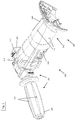
With the foregoing in mind,FIGS. 1 and2 are perspective views of an embodiment asystem 100 comprising apower tool 101 and anautomatic safety system 102 communicatively coupled to the power tool. Thepower tool 101 is embodied as an angle grinder. In the illustrated embodiment, theangle grinder 101 includes anautomatic safety system 102 communicatively coupled to theangle grinder 101. In certain embodiments, theautomatic safety system 102 includes amain detector 104, aside handle 106, and abody sleeve 108. As further described with respect toFIGS. 3-5 , theautomatic safety system 102 is configured to execute an automated safety protocol with one or more safety checks. In particular, after successful completion of the automated safety protocol, theautomatic safety system 102 may be configured to send an activation signal to the control unit of theangle grinder 101. The activation signal provided to the control unit of theangle grinder 101 allows theangle grinder 101 to be engaged for operation. - In certain embodiments, the
angle grinder 101 includes a gear housing, a disc holder, a disc accessory configured to couple to the disc holder. The gear housing and the disc accessory are not shown in the figures. - In particular, the gear housing includes a control unit configured to receive one or more activation signals from the
automatic safety system 102, as further explained with respect toFIG. 5 . The control unit is not shown in the figures. The control unit may be configured to unlock theangle grinder 101, so that the operator is allowed to engage theangle grinder 101 by pushing the "START" or "ON" button. In certain embodiments, such as when theangle grinder 101 fails to successfully pass each safety check of the automatic safety protocol, the control unit may not receive any activation signals from theautomatic safety system 102, and theangle grinder 101 will remain in a safety lock position. In the safety lock position, theangle grinder 101 may be inoperable when the operator pushes the "START" or "ON" button. Accordingly, in this manner, theangle grinder 101 may be configured to reduce the likelihood of an accidental start and/or operation of theangle grinder 101 prior to a safety check of one or more components. - In certain embodiments, the
automatic safety system 102 may be coupled to thebody 110 of theangle grinder 101. In particular, theautomatic safety system 102 includes abody sleeve 108 that is configured to conform to the external shape of thebody 110. For example, thebody sleeve 108 may be configured to wrap around a portion of thebody 110, thereby securing theautomatic safety system 102 to theangle grinder 101. In certain embodiments, the side handle 106 may be coupled to themain detector 102 of theautomatic safety system 102, as further described with respect toFIG. 3 . In certain embodiments, themain detector 102 may include anextension 112 that is configured to couple two sides of themain detector 102. Further, each side of themain detector 102 may include an attachment 114 (shown inFIG. 3 ) that secure themain detector 102 around thebody 110 of theangle grinder 101. In certain embodiments, theextension 112 may be conformed to fit the external surfaces of thebody 110 and/or may be configured to fit into a groove of the external surface of thebody 100. In certain embodiments, theattachment 114 may additionally couple the side handle 106 to themain detector 102. - In certain embodiments, a
user interface 115 may be disposed on themain detector 104, and include one or more visual indicia configured to provide information to an operator regarding the status of one or more safety or operating parameters. In certain embodiments, theuser interface 115 may include one or more LEDs indicators of one or more different colors, such that each color identifies a status of a different feature or component. For example, in certain embodiments, an LED light and color may be utilized to indicate whether a protection guard is installed properly. Likewise, in certain embodiments, an LED light may be utilized to indicate whether the side handle 106 is installed properly. Similarly, in other embodiments, other types of visual indicia, (e.g., text, pictures, patterns of light, alerts, etc.) may be utilized to indicate information to the operator. In certain embodiments, a graphics display may be utilized to display safety and/or operating features derived from the safety protocol executed by theautomatic safety system 100. In certain embodiments, additional information, such as status of wireless communication, may be displayed and/or communicated to an operator via theuser interface 115. -
FIG. 3 is a perspective view of an embodiment of theautomatic safety system 100 ofFIG. 1 , having themain detector 104, thesafety handle 106, and thebody sleeve 108, in accordance with aspects of the present embodiments. Further, the illustrated embodiment depicts one or more sensors 116 (or sensing devices 116) disposed on theautomatic safety system 100 and configured to gather safety and operating information related to theangle grinder 101. - In certain embodiments, the one or
more sensing devices 116 orsensors 116 may be configured throughout theangle grinder 101. In certain embodiments, thesensors 116 may be configured for a specific function and may be located in a specific location. For example, a side handle detection sensor (or switch) may be located proximate to the connection between the side handle 106 and themain detector 104, and may be configured to provide a status signal regarding the position and depth of theside handle 106. Specifically, thesensor 116 may be positioned proximate to theattachments 114, and thesensor 116 may be configured to determine the depth or position to which the side handle 106 is installed with respect to theattachment 114. The signal information related to the position and depth of the side handle 106 may be utilized to determine whether the side handle 106 is properly installed. As a further example, a guard detection sensor (or switch) may be located proximate to the protection guard, and may be configured to provide a status signal regarding whether the protection guard was properly installed. - In certain embodiments, the
sensors 116 may be configured to gather other types of information, such as information related to the dust hood and/or the disc selection. For example, thesensor 116 may be a touch sensor (e.g., membrane switch or other kind of thin layer sensor) that is attached near the installation interface to detect the dust hood. When the dust hood is installed, thesensor 116 may be turned on by physical contact, and a signal may be sent to the controller of the main detector to indicate that the dust hood is installed. Similarly, thesensor 116 may be a touch sensor (e.g., membrane switch or other kind of thin layer sensor) that is attached near the gear housing to detect the disc. When the protection guard is installed, thesensor 116 may be turned on by physical contact, and a signal may be sent to thecontroller 122 of themain detector 104 indicating the disc is installed. - In certain embodiments, the sensors may be position/orientation sensors, and may be disposed in locations where an orientation or position of the
angle grinder 101 is needed. For example, in certain embodiments, one or more sensors may be disposed on theside handle 106, and maybe configured to determine whether the side handle 106 is properly held or positioned by an operator. Similarly, position/orientation sensors may be disposed on thebody 110 or thebody sleeve 108 to determine the same. In certain embodiments, thesensors 116 may be pressure sensors that detect whether an operator is in physical contact with theangle grinder 101 in appropriate locations. Indeed, any type of sensor (e.g., accelerometers, temperature sensors, proximity and displacement sensors, image sensors, touch sensors, level sensors, gyroscopes, force, or speed sensors, etc.) may be utilized to gather safety and/or operating parameter information related to theangle grinder 101. Specifically, as further discussed with respect toFIGS. 4 and5 , the sensors may be triggered based on an automatic safety protocol executed by themain detector 104 of theautomatic safety system 100. Further, as described with respect toFIGS. 4 and5 , based on the information received, theautomatic safety system 100 may be configured to send an activation signal to the control unit of theangle grinder 101. - In certain embodiments, interface circuity 120 (e.g., wires) may be provided through the
automatic safety system 100 to communicatively couple thesensors 116 with themain detector 104. For example, one or more wires may extend between thebody sleeve 108 and themain detector 104, between the side handle 106 and themain detector 104, as well as through theextension 112 of themain detector 104. -
FIG. 4 is a schematic view of an embodiment of theautomatic safety system 100 ofFIG. 1 , illustrating themain detector 104 having acontroller 122 configured to interface (via the interface circuity 120) with one ormore sensing devices 116 of theangle grinder 101. In certain embodiments, themain detector 104 may includecommunications circuitry 124 having awireless module 126 and atransceiver 128. As noted above, theuser interface 115 may include (optionally) adisplay 130 and one ormore LEDS 132. - In certain embodiments, the
controller 122 may be communicatively coupled to aprocessor 134 and amemory 136. Theprocessor 134 may be configured to execute instructions stored on thememory 136 to carry out the automatic safety protocol operations of theautomatic safety system 100. Thememory 136 may be configured to store instructions that are loadable and executable on theprocessor 134. In certain embodiments, thememory 136 may be volatile (such as random access memory (RAM)) and/or non-volatile (such as read-only memory (ROM), flash memory, etc.). Thecontroller 122 may also include additional removable storage and/or non-removable storage including, but not limited to, magnetic storage, optical disks, and/or tape storage. In some implementations, thememory 136 may include multiple different types of memory, such as static random access memory (SRAM), dynamic random access memory (DRAM), or ROM. - In particular, the
controller 122 may be configured to execute instructions that carry out the automatic safety protocol operations, and may be configured to receive data/information from the one ormore sensors 116. For example, when triggered, the automatic safety protocol may conduct a series of safety checks throughout theangle grinder 101, as further described with respect toFIG. 5 . Each safety check may be an executable instruction that is configured to check the safety or operability status of a component or a feature of theangle grinder 101. In certain embodiments, thesensors 116 may be configured to automatically provide data or information to thecontroller 122. In certain embodiments, an operator can initiate the safety protocol by pressing a button or indicating a command through theuser interface 115 of theangle grinder 101. In response to each safety check, asensor 116 may be configured to provide a detection signal regarding a status (information/data) of the component or feature to thecontroller 122. Based on the received information, thecontroller 122 may be configured to determine whether theangle grinder 101 passed the safety check or failed the safety check. Once all of the safety checks (or a desired number or a desired type of safety checks) are positively passed, thecontroller 122 may be configured to send an activation signal to the control unit of theangle grinder 101. - In certain embodiments, the
main detector 104 may include apower source 138. Thepower source 138 may be a replaceable and/or rechargeable power source (e.g., battery powered) disposed within themain detector 104. In certain embodiments, themain detector 104 may be powered by a power source disposed within theside handle 106, or may be powered via an external power source. - In certain embodiments, the
main detector 104 may includecommunications circuitry 124 having awireless module 126 and/or atransceiver 128. In certain embodiments, themain detector 104 may be configured to transmit the information gathered by thesensors 116 to the control unit of theangle grinder 101. In such embodiments, themain detector 104 may or may not include acontroller 122,processor 134, and/or amemory 136 to execute and/or process information. In other embodiments, themain detector 104 may be configured to receive and analyze the information received from thesensors 116 to determine whether theangle grinder 101 is ready to be operated. In either embodiment, the wireless module may be utilized to transmit data and/or the activation signal to the main control of theangle grinder 101. In certain embodiments, thewireless module 126 and/or thetransceiver 128 may be incorporated in the control unit of theangle grinder 101. -
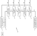
FIG. 5 is an embodiment of aprocess 140 for executing an automatic safety protocol for theangle grinder 101 ofFIG. 1 , where the automatic safety protocol is executed prior to activating theangle grinder 101 for operation. In the illustrated embodiment, one or more steps of theprocess 140 may be executable by thecontroller 122 of themain detector 104 and/or by a master control unit of theangle grinder 101. Master control unit is not shown in the figures. In certain embodiments, theprocess 140 includes receiving one or more signals from the sensor 116 (block 142) and performing a series of safety checks on the angle grinder 101 (block 144). Specifically, in certain embodiments, theprocess 140 includes determining if the safety handle is properly installed (block 146), determining if the guard is properly installed (block 148), and/or determining if the device is properly oriented (block 150) (e.g., determining if the side handle 106 and/or thebody sleeve 108 and/or thebody 110 is properly held and/or positioned). In certain embodiments, theprocess 140 includes determining if the proper disc is selected and/or installed (block 152), and/or determining if dust hood is properly installed (block 154). If the signals received from thesensors 116 indicate that the safety features are in alignment with the desired status, theprocess 140 is configured to send an activation signal to the master control unit of theangle grinder 101. In certain embodiments, the activation signal is configured to unlock theangle grinder 101, so that the operator may engage theangle grinder 101 for use. - This written description uses examples to disclose the invention, including the best mode, and also to enable any person skilled in the art to practice the invention, including making and using any devices or systems and performing any incorporated methods. The patentable scope of the invention is defined by the claims, and may include other examples that occur to those skilled in the art. Such other examples are intended to be within the scope of the claims if they have structural elements that do not differ from the literal language of the claims, or if they include equivalent structural elements with insubstantial differences from the literal language of the claims.
Claims (15)
- A system (100), comprising:a power tool (102); andan automatic safety system (102) communicatively coupled to the power tool (101),characterized in that one or more sensors (116) disposed about the power tool (101), wherein the one or more sensors (116) are configured to gather data about a safety parameter related to an operation of the power tool (101); and a main detector (104) configured to receive the data gathered by the one or more sensors (116), wherein the main detector (104) is configured to analyze the received data to determine whether to unlock the power tool (101) for operation.
- The system (100) of claim 1,
characterized in that the main detector (104) comprises a wireless module configured to transmit information to a master control unit of the power tool (101). - The system (100) of claim 2,
characterized in that the main detector (104) is configured to transmit an activation signal to the master control unit of the power tool (101) to unlock the power tool (101) for operation. - The system (100) of claim 1,
characterized in that the automatic safety system (102) comprises interface circuitry configured to transmit information from the one or more sensors (116) to the main detector (104). - The system (100) of claim 1,
characterized in that the one or more sensors (116) comprises a safety handle sensor, and wherein the main detector (104) is configured to receive data from the safety handle sensor to determine if a side handle (106) of the power tool (101) is properly installed. - The system (100) of claim 1,
characterized in that the one or more sensors (116) comprises a guard detection sensor, and wherein the main detector (104) is configured to receive data from the guard detection sensor to determine if a protection guard of the power tool (101) is properly installed. - The system (100) of claim 1,
characterized in that the one or more sensors (116) comprises a tool detection sensor, and wherein the main detector (104) is configured to receive data from the tool detection sensor to determine if a tool of the power tool (101) is properly installed. - The system (100) of claim 1,
characterized in that the one or more sensors (116) comprises a dust hood detection sensor, and wherein the main detector (104) is configured to receive data from the dust hoot detection sensor to determine if a dust hood of the power tool (101) is properly installed. - The system (100) of claim 1,
characterized in that the one or more sensors (116) comprises a touch sensor, a position/orientation sensor, a force sensor, or a combination thereof. - A method for controlling a power tool
characterized by the steps- receiving, via a main detector (104), one or more signals from one or more sensors (116) disposed about the power tool (101), wherein the one or more sensors (116) are configured to gather data about a safety parameter related to an operation of a power tool (101);- determining, via the main detector (104), whether to unlock the power tool (101) for operation based on the data received from the one or more sensors (116); and- sending an activation signal to a control unit of the power tool (101), via the main detector (104), to unlock the power tool (101) for operation. - The method of claim 10,
characterized in that the power tool (101) is an angle grinder utilized on a construction site. - The method of claim 10,
characterized in that determining whether to unlock the power tool (101) comprises determining if a safety handle of the power tool (101) is properly installed. - The method of claim 10,
characterized in that determining whether to unlock the power tool (101) comprises determining if a protection guard of the power tool (101) is properly installed. - The method of claim 10,
characterized in that determining whether to unlock the power tool (101) comprises determining if the power tool (101) is properly held and oriented by an operator. - The method of claim 10,
characterized in that determining whether to unlock the power tool (101) comprises determining if a tool of the power tool (101) is properly installed or if a dust hood of the power tool (101) is properly installed.
Priority Applications (5)
| Application Number | Priority Date | Filing Date | Title |
|---|---|---|---|
| EP17205622.8A EP3495899A1 (en) | 2017-12-06 | 2017-12-06 | System and method for an automatic safety protocol in electrical tools |
| US16/756,375 US20210187697A1 (en) | 2017-12-06 | 2018-11-21 | Systems and methods for an automatic safety protocol in electrical tools |
| EP18801005.2A EP3721299A1 (en) | 2017-12-06 | 2018-11-21 | System and method for an automatic safety protocol in electrical tools |
| PCT/EP2018/082066 WO2019110303A1 (en) | 2017-12-06 | 2018-11-21 | System and method for an automatic safety protocol in electrical tools |
| CN201880077171.0A CN111542788A (en) | 2017-12-06 | 2018-11-21 | System and method for automatic safety protocol in power tool |
Applications Claiming Priority (1)
| Application Number | Priority Date | Filing Date | Title |
|---|---|---|---|
| EP17205622.8A EP3495899A1 (en) | 2017-12-06 | 2017-12-06 | System and method for an automatic safety protocol in electrical tools |
Publications (1)
| Publication Number | Publication Date |
|---|---|
| EP3495899A1 true EP3495899A1 (en) | 2019-06-12 |
Family
ID=60654695
Family Applications (2)
| Application Number | Title | Priority Date | Filing Date |
|---|---|---|---|
| EP17205622.8A Withdrawn EP3495899A1 (en) | 2017-12-06 | 2017-12-06 | System and method for an automatic safety protocol in electrical tools |
| EP18801005.2A Withdrawn EP3721299A1 (en) | 2017-12-06 | 2018-11-21 | System and method for an automatic safety protocol in electrical tools |
Family Applications After (1)
| Application Number | Title | Priority Date | Filing Date |
|---|---|---|---|
| EP18801005.2A Withdrawn EP3721299A1 (en) | 2017-12-06 | 2018-11-21 | System and method for an automatic safety protocol in electrical tools |
Country Status (4)
| Country | Link |
|---|---|
| US (1) | US20210187697A1 (en) |
| EP (2) | EP3495899A1 (en) |
| CN (1) | CN111542788A (en) |
| WO (1) | WO2019110303A1 (en) |
Cited By (6)
| Publication number | Priority date | Publication date | Assignee | Title |
|---|---|---|---|---|
| JP2021024051A (en) * | 2019-08-07 | 2021-02-22 | 株式会社マキタ | Impact tool |
| WO2021073791A1 (en) * | 2019-10-17 | 2021-04-22 | Festool Gmbh | Assistance device, tool apparatus and method for operating a tool apparatus |
| CN113040923A (en) * | 2019-12-27 | 2021-06-29 | 重庆海扶医疗科技股份有限公司 | Operation controller and hovering control method thereof |
| DE102021104618A1 (en) | 2021-02-26 | 2022-09-01 | Robert Bosch Gesellschaft mit beschränkter Haftung | Adapter device for a hand tool machine |
| DE102022203429A1 (en) | 2022-04-06 | 2023-10-12 | Robert Bosch Gesellschaft mit beschränkter Haftung | Energy storage, method for adapting an additional parameter of an energy storage, electrical device and electrical device system |
| EP4327985A1 (en) * | 2022-08-24 | 2024-02-28 | Milwaukee Electric Tool Corporation | Power tool including a touch sensor |
Families Citing this family (1)
| Publication number | Priority date | Publication date | Assignee | Title |
|---|---|---|---|---|
| US20230158658A1 (en) * | 2021-11-24 | 2023-05-25 | Milwaukee Electric Tool Corporation | Grinder including enhanced sensing and component detection |
Citations (2)
| Publication number | Priority date | Publication date | Assignee | Title |
|---|---|---|---|---|
| US5666010A (en) * | 1995-08-30 | 1997-09-09 | Stratiotis; Gus | Safety system for machine tools |
| US20170008159A1 (en) * | 2014-01-27 | 2017-01-12 | Robert Bosch Gmbh | Machine Tool Device |
Family Cites Families (14)
| Publication number | Priority date | Publication date | Assignee | Title |
|---|---|---|---|---|
| US4959906A (en) * | 1989-08-28 | 1990-10-02 | Moore Jr Marvin J | Safety device for chain saws |
| US6418829B1 (en) * | 1994-05-06 | 2002-07-16 | Thomas Stanley Pilchowski | Power tool safety device |
| US7217069B2 (en) * | 2000-02-10 | 2007-05-15 | Eastway Fair Company Limited | Hand-held tool with a removable object sensor |
| DE60238424D1 (en) * | 2001-07-11 | 2011-01-05 | Black & Decker Inc | Safety mechanisms for a power tool |
| DE10141161A1 (en) * | 2001-08-16 | 2003-02-27 | C & E Fein Gmbh & Co Kg | Optical control device |
| DE10248924A1 (en) * | 2002-10-17 | 2004-04-29 | C. & E. Fein Gmbh & Co Kg | power tool |
| DE10360165A1 (en) * | 2003-12-20 | 2005-09-29 | C. & E. Fein Gmbh | power tool |
| JP4478697B2 (en) * | 2007-03-23 | 2010-06-09 | 株式会社村上開明堂 | Valve socket |
| US8919231B2 (en) * | 2008-11-19 | 2014-12-30 | Power Tool Institute | Safety mechanisms for power tools |
| US8517642B2 (en) * | 2009-02-11 | 2013-08-27 | Phil Borunda | Tool mounted stud finder |
| US8752301B2 (en) * | 2009-04-08 | 2014-06-17 | Rex George | Chainsaw incorporating a safety device system |
| DE102010027981A1 (en) * | 2010-04-20 | 2011-10-20 | Robert Bosch Gmbh | angle |
| WO2014164973A1 (en) * | 2013-03-12 | 2014-10-09 | Robert Bosch Gmbh | Guard detection system for a power tool |
| US9114498B1 (en) * | 2014-10-24 | 2015-08-25 | Velasa Sports, Inc. | Skate blade sharpening system with protective covers |
-
2017
- 2017-12-06 EP EP17205622.8A patent/EP3495899A1/en not_active Withdrawn
-
2018
- 2018-11-21 CN CN201880077171.0A patent/CN111542788A/en active Pending
- 2018-11-21 EP EP18801005.2A patent/EP3721299A1/en not_active Withdrawn
- 2018-11-21 US US16/756,375 patent/US20210187697A1/en active Pending
- 2018-11-21 WO PCT/EP2018/082066 patent/WO2019110303A1/en unknown
Patent Citations (2)
| Publication number | Priority date | Publication date | Assignee | Title |
|---|---|---|---|---|
| US5666010A (en) * | 1995-08-30 | 1997-09-09 | Stratiotis; Gus | Safety system for machine tools |
| US20170008159A1 (en) * | 2014-01-27 | 2017-01-12 | Robert Bosch Gmbh | Machine Tool Device |
Cited By (6)
| Publication number | Priority date | Publication date | Assignee | Title |
|---|---|---|---|---|
| JP2021024051A (en) * | 2019-08-07 | 2021-02-22 | 株式会社マキタ | Impact tool |
| WO2021073791A1 (en) * | 2019-10-17 | 2021-04-22 | Festool Gmbh | Assistance device, tool apparatus and method for operating a tool apparatus |
| CN113040923A (en) * | 2019-12-27 | 2021-06-29 | 重庆海扶医疗科技股份有限公司 | Operation controller and hovering control method thereof |
| DE102021104618A1 (en) | 2021-02-26 | 2022-09-01 | Robert Bosch Gesellschaft mit beschränkter Haftung | Adapter device for a hand tool machine |
| DE102022203429A1 (en) | 2022-04-06 | 2023-10-12 | Robert Bosch Gesellschaft mit beschränkter Haftung | Energy storage, method for adapting an additional parameter of an energy storage, electrical device and electrical device system |
| EP4327985A1 (en) * | 2022-08-24 | 2024-02-28 | Milwaukee Electric Tool Corporation | Power tool including a touch sensor |
Also Published As
| Publication number | Publication date |
|---|---|
| EP3721299A1 (en) | 2020-10-14 |
| WO2019110303A1 (en) | 2019-06-13 |
| US20210187697A1 (en) | 2021-06-24 |
| CN111542788A (en) | 2020-08-14 |
Similar Documents
| Publication | Publication Date | Title |
|---|---|---|
| EP3495899A1 (en) | System and method for an automatic safety protocol in electrical tools | |
| US20110313625A1 (en) | Coupler with coupling status sensors | |
| EP3296064B1 (en) | Depth and angle sensor attachment for a power tool | |
| WO2013116303A1 (en) | Power tool | |
| JP4582503B2 (en) | Safety belt device for work | |
| EP2774502A1 (en) | Shoe comprising sensors | |
| WO2012035813A1 (en) | Power hand tool | |
| US10850377B2 (en) | Hand-held power tool, and method for operation | |
| CN106457552B (en) | Hand tool system and driving method | |
| EP2722201B1 (en) | Tire pressure sensor device setting method | |
| US20210394326A1 (en) | Machine Tool Device for Open-Loop and/or Closed-Loop Control of at least One Machine Tool Function of a Machine Tool | |
| JP4585572B2 (en) | Two-hand operation switch device | |
| CN105593771B (en) | Control system for a machine tool, operator control station and mobile data carrier | |
| KR20170129021A (en) | Smart phone touch remote control for bike | |
| EP3140092B1 (en) | Improved power tool | |
| KR101825351B1 (en) | Portable electric sawing devices | |
| KR101847511B1 (en) | Electric tool recognizing predetermined worker | |
| EP2381331B1 (en) | Joystick for the execution of controls on operating machines | |
| KR102426310B1 (en) | A Sensor Module for a Chin Strap of a Safety Cap and a Method for Checking a Wearing Condition of the Safety Cap | |
| JP2007086291A (en) | Optical connector locking implement | |
| KR20230050383A (en) | remote control unit | |
| EP3272466B1 (en) | Method for operating a hand-held machine tool | |
| KR101514182B1 (en) | Control method for setting teaching value of machine tool | |
| DE102019200323A1 (en) | Machine tool | |
| JP2006175838A (en) | Circular saw system |
Legal Events
| Date | Code | Title | Description |
|---|---|---|---|
| PUAI | Public reference made under article 153(3) epc to a published international application that has entered the european phase |
Free format text: ORIGINAL CODE: 0009012 |
|
| AK | Designated contracting states |
Kind code of ref document: A1 Designated state(s): AL AT BE BG CH CY CZ DE DK EE ES FI FR GB GR HR HU IE IS IT LI LT LU LV MC MK MT NL NO PL PT RO RS SE SI SK SM TR |
|
| AX | Request for extension of the european patent |
Extension state: BA ME |
|
| STAA | Information on the status of an ep patent application or granted ep patent |
Free format text: STATUS: THE APPLICATION IS DEEMED TO BE WITHDRAWN |
|
| 18D | Application deemed to be withdrawn |
Effective date: 20191213 |