EP3495785A1 - Ultrasonic fluid measurement probe with ultrasonically welded base cap - Google Patents
Ultrasonic fluid measurement probe with ultrasonically welded base cap Download PDFInfo
- Publication number
- EP3495785A1 EP3495785A1 EP18210595.7A EP18210595A EP3495785A1 EP 3495785 A1 EP3495785 A1 EP 3495785A1 EP 18210595 A EP18210595 A EP 18210595A EP 3495785 A1 EP3495785 A1 EP 3495785A1
- Authority
- EP
- European Patent Office
- Prior art keywords
- transducer
- ultrasonic
- transducer chamber
- wiring channel
- cap
- Prior art date
- Legal status (The legal status is an assumption and is not a legal conclusion. Google has not performed a legal analysis and makes no representation as to the accuracy of the status listed.)
- Granted
Links
Images


Classifications
-
- A—HUMAN NECESSITIES
- A61—MEDICAL OR VETERINARY SCIENCE; HYGIENE
- A61B—DIAGNOSIS; SURGERY; IDENTIFICATION
- A61B8/00—Diagnosis using ultrasonic, sonic or infrasonic waves
- A61B8/06—Measuring blood flow
-
- G—PHYSICS
- G01—MEASURING; TESTING
- G01F—MEASURING VOLUME, VOLUME FLOW, MASS FLOW OR LIQUID LEVEL; METERING BY VOLUME
- G01F23/00—Indicating or measuring liquid level or level of fluent solid material, e.g. indicating in terms of volume or indicating by means of an alarm
- G01F23/22—Indicating or measuring liquid level or level of fluent solid material, e.g. indicating in terms of volume or indicating by means of an alarm by measuring physical variables, other than linear dimensions, pressure or weight, dependent on the level to be measured, e.g. by difference of heat transfer of steam or water
- G01F23/28—Indicating or measuring liquid level or level of fluent solid material, e.g. indicating in terms of volume or indicating by means of an alarm by measuring physical variables, other than linear dimensions, pressure or weight, dependent on the level to be measured, e.g. by difference of heat transfer of steam or water by measuring the variations of parameters of electromagnetic or acoustic waves applied directly to the liquid or fluent solid material
- G01F23/296—Acoustic waves
- G01F23/2962—Measuring transit time of reflected waves
-
- G—PHYSICS
- G01—MEASURING; TESTING
- G01F—MEASURING VOLUME, VOLUME FLOW, MASS FLOW OR LIQUID LEVEL; METERING BY VOLUME
- G01F1/00—Measuring the volume flow or mass flow of fluid or fluent solid material wherein the fluid passes through a meter in a continuous flow
- G01F1/66—Measuring the volume flow or mass flow of fluid or fluent solid material wherein the fluid passes through a meter in a continuous flow by measuring frequency, phase shift or propagation time of electromagnetic or other waves, e.g. using ultrasonic flowmeters
-
- G—PHYSICS
- G01—MEASURING; TESTING
- G01F—MEASURING VOLUME, VOLUME FLOW, MASS FLOW OR LIQUID LEVEL; METERING BY VOLUME
- G01F23/00—Indicating or measuring liquid level or level of fluent solid material, e.g. indicating in terms of volume or indicating by means of an alarm
- G01F23/22—Indicating or measuring liquid level or level of fluent solid material, e.g. indicating in terms of volume or indicating by means of an alarm by measuring physical variables, other than linear dimensions, pressure or weight, dependent on the level to be measured, e.g. by difference of heat transfer of steam or water
- G01F23/28—Indicating or measuring liquid level or level of fluent solid material, e.g. indicating in terms of volume or indicating by means of an alarm by measuring physical variables, other than linear dimensions, pressure or weight, dependent on the level to be measured, e.g. by difference of heat transfer of steam or water by measuring the variations of parameters of electromagnetic or acoustic waves applied directly to the liquid or fluent solid material
- G01F23/296—Acoustic waves
-
- G—PHYSICS
- G01—MEASURING; TESTING
- G01F—MEASURING VOLUME, VOLUME FLOW, MASS FLOW OR LIQUID LEVEL; METERING BY VOLUME
- G01F15/00—Details of, or accessories for, apparatus of groups G01F1/00 - G01F13/00 insofar as such details or appliances are not adapted to particular types of such apparatus
- G01F15/14—Casings, e.g. of special material
Definitions
- the present disclosure relates generally to systems and methods for ultrasonic fluid measurement. More particularly, the present disclosure relates to an ultrasonic fluid measurement probe for measuring the level of fluid in a container, such as for measuring the level of fuel in a fuel tank on an aircraft or other vehicle.
- Ultrasonic sensing uses ultrasonic transducers to transmit ultrasonic waves and to receive those ultrasonic waves reflected by an object. The time delay between transmission and reception of the ultrasonic waves may be used to determine the distance of the object from an ultrasonic transducer. Ultrasonic transducers may be used to determine the height or level of fluid in a container by reflecting an ultrasonic signal from the surface of the fluid in the container. For example, without limitation, ultrasonic sensing may be used for fuel gauging, to measure the level of fuel in a fuel tank on an aircraft or other vehicle.
- a current fuel probe assembly is comprised of a piezoelectric transducer that is glued to a plastic base inside a cavity.
- the transducer has wires soldered to it.
- a foam pad is placed on top of the transducer to create an air space.
- the foam pad is covered by a polysulfide potting material to seal out fuel from the air space created by the foam pad.
- an apparatus comprises a base, an ultrasonic transducer, and a cap.
- the base comprises a transducer chamber, wherein the transducer chamber comprises a transducer chamber floor, a transducer chamber edge, and transducer chamber walls extending from the transducer chamber floor to the transducer chamber edge.
- the ultrasonic transducer is attached to the transducer chamber floor.
- the cap is welded to the transducer chamber edge such that the cap, along with the transducer chamber floor and the transducer chamber walls, encloses the transducer chamber to form an enclosed air space between the ultrasonic transducer and the cap.
- a method of enhancing reliability of an ultrasonic fluid measurement probe comprises generating an ultrasonic signal by an ultrasonic transducer in a base of the ultrasonic fluid measurement probe such that the ultrasonic signal is directed into a tube attached to the base of the ultrasonic fluid measurement probe and detecting a reflection of the ultrasonic signal by the ultrasonic transducer.
- the ultrasonic transducer is in a transducer chamber in the base of the ultrasonic fluid measurement probe.
- the transducer chamber comprises a transducer chamber floor, transducer chamber walls, and a cap welded to an edge of the transducer chamber walls such that the cap, along with the transducer chamber floor and the transducer chamber walls, encloses the transducer chamber to form an enclosed air space.
- a method of enhancing reliability of an ultrasonic fluid measurement probe comprises attaching an ultrasonic transducer to a transducer chamber floor of a transducer chamber in a base.
- the transducer chamber comprises the transducer chamber floor, a transducer chamber edge, and transducer chamber walls extending from the transducer chamber floor to the transducer chamber edge.
- a cap is welded to the transducer chamber edge such that the cap, along with the transducer chamber floor and the transducer chamber walls, encloses the transducer chamber to form an enclosed air space between the ultrasonic transducer and the cap.
- An embodiment comprises an apparatus that includes a base comprising a transducer chamber, wherein the transducer chamber comprises a transducer chamber floor, a transducer chamber edge, and transducer chamber walls extending from the transducer chamber floor to the transducer chamber edge; an ultrasonic transducer attached to the transducer chamber floor; and a cap welded to the transducer chamber edge and that, along with the transducer chamber floor and the transducer chamber walls, encloses the transducer chamber to form an enclosed air space between the ultrasonic transducer and the cap.
- the base may further include a flange portion, and a mounting hole in the flange portion.
- the base may also include a wiring channel in communication with the transducer chamber, wherein the wiring channel comprises a wiring channel floor, a wiring channel edge, and wiring channel walls extending from the wiring channel floor to the wiring channel edge; and wherein the cap is welded to the wiring channel edge.
- the apparatus may also include wires attached to the ultrasonic transducer and extending from the ultrasonic transducer, through the transducer chamber, through the wiring channel, and through the wiring channel floor. The wires may be soldered to the ultrasonic transducer.
- the ultrasonic transducer may be a piezoelectric transducer.
- the cap may be made of plastic. This will enhance the design as a result of a decrease in weight while not impacting performance or reliability.
- the cap may be fabricated from polyphenylene sulphide.
- the apparatus may also include a tube attached to the base such that an ultrasonic signal generated by the ultrasonic transducer is directed into the tube.
- the base may be attached to an inside surface of a fuel tank on an aircraft such that the tube extends from the base into the fuel tank.
- Another embodiment comprises a method of enhancing reliability of an ultrasonic fluid measurement probe that may include generating an ultrasonic signal by an ultrasonic transducer in a transducer chamber in a base of the ultrasonic fluid measurement probe such that the ultrasonic signal is directed into a tube attached to the base of the ultrasonic fluid measurement probe, wherein the transducer chamber comprises a transducer chamber floor, transducer chamber walls, and a cap welded to an edge of the transducer chamber walls such that the cap, along with the transducer chamber floor and the transducer chamber walls, encloses the transducer chamber to form an enclosed air space; and detecting a reflection of the ultrasonic signal by the ultrasonic transducer.
- the method may also include processing the detected reflection of the ultrasonic signal to determine a level of fluid in a container. This can enhance performance and reliability. Processing the detected reflection of the ultrasonic signal to determine the level of fluid in a container may include processing the detected reflection of the ultrasonic signal to determine a level of fuel in a fuel tank.
- Another embodiment comprises a method of enhancing reliability of an ultrasonic fluid measurement probe that includes attaching an ultrasonic transducer to a transducer chamber floor of a transducer chamber in a base, wherein the transducer chamber comprises the transducer chamber floor, a transducer chamber edge, and transducer chamber walls extending from the transducer chamber floor to the transducer chamber edge; and welding a cap to the transducer chamber edge such that the cap, along with the transducer chamber floor and the transducer chamber walls, encloses the transducer chamber to form an enclosed air space between the ultrasonic transducer and the cap.
- the base may also include a wiring channel in communication with the transducer chamber, wherein the wiring channel may also include a wiring channel floor, a wiring channel edge, and wiring channel walls extending from the wiring channel floor to the wiring channel edge, and may also include welding the cap to the wiring channel edge.
- the method may also include attaching wires to the ultrasonic transducer; and extending the wires from the ultrasonic transducer, through the transducer chamber, through the wiring channel, and through the wiring channel floor.
- the cap may be made of plastic.
- the cap may be made of polyphenylene sulphide. Welding the cap to the transducer chamber edge may include ultrasonically welding the cap to the transducer chamber edge.
- the method may also include attaching a tube to the base such that an ultrasonic signal generated by the ultrasonic transducer is directed into the tube.
- the illustrative embodiments recognize and take into account different considerations. For example, the illustrative embodiments recognize and take into account that ultrasonic fuel measuring probes in fuel tanks on aircraft may be subject to extreme environmental conditions which may cause them to need to be repaired or replaced prematurely. An aircraft may need to be removed from service and maintenance personnel may need to perform a fuel tank entry when an ultrasonic fuel probe in an aircraft fuel tank needs to be repaired or replaced. Fuel tank entry by maintenance personnel to repair or replace a fuel probe requires draining and purging of the fuel tank. In many cases, repair or replacement of an ultrasonic fuel probe in the fuel tank of an aircraft may require up to two days of down time in which the aircraft is out of service. Such down time may be very costly to an airline or other operator of the aircraft.
- ultrasonic fuel measurement probes there may be relatively very many ultrasonic fuel measurement probes on an aircraft.
- a Boeing 777-300ER passenger aircraft may use 76 ultrasonic fuel measurement probes in a fuel quantity indicating system.
- Illustrative embodiments recognize and take into account that reliability for commercial passenger aircraft and other aircraft may be improved and the cost of operating such aircraft reduced by reducing the need to repair or replace the ultrasonic fuel measurement probes that may be used for fuel gauging in such aircraft.
- Illustrative embodiments recognize and take into account that the polysulfide potting around the transducer in the base of a conventional ultrasonic fuel measurement probe may not perform as desired and thereby may allow fuel ingress into the foam pad area of the transducer. Fuel in the foam pad compromises the air space around the transducer and may result in the transducer being sensitive to reflections from the opposite direction it was intended to. This sensitivity to reflections from the opposite direction than intended may result in a reading from the ultrasonic transducer of a fuel height corresponding to the distance between the ultrasonic transducer and the bottom of the fuel tank on which the ultrasonic fuel measurement probe is placed.
- a conventional ultrasonic fuel measurement probe in which an inconsistency in the polysulfide potting material results in fuel in the foam pad area around the ultrasonic transducer may provide a reading that indicates a fuel height of one or two centimeters regardless of the actual height of fuel in the fuel tank.
- Illustrative embodiments recognize and take into account that the polysulfide potting material in the base of an ultrasonic fuel measurement probe that is used to measure fuel height in an aircraft fuel tank may flex as the aircraft changes altitude from ground level to cruise altitude. Air trapped in the air space between the polysulfide potting material and the ultrasonic transducer remains at ground level pressure, therefore, the polysulfide potting material must endure a pressure difference between the pressure at ground level and the pressure at cruise level.
- the polysulfide potting material may be required to endure a pressure difference between sea level pressure in the air space on one side of the polysulfide potting material and the pressure at a cruising altitude near 40,000 feet above sea level on the other side of the polysulfide potting material.
- a pressure differential may cause the polysulfide potting material to expand under internal pressure from the air in the air space as the aircraft climbs from the ground to cruising altitude and then contract again as the aircraft descends from cruising altitude to the ground for landing.
- This cyclic mechanical stress may eventually compromise the seal of the polysulfide potting material.
- This cyclic mechanical stress also may cause tension in the wires that are soldered to the ultrasonic transducer disk, which may cause inconsistencies in the solder joints.
- Illustrative embodiments also recognize and take into account that various manufacturing issues may be associated with the use of polysulfide potting material in the base of an ultrasonic fluid measurement probe. For example, without limitation, contamination of the polysulfide potting material, achieving the appropriate ratio of materials that may be mixed together to form the polysulfide potting material, and achieving an acceptable consistency in the thickness of the polysulfide potting material deposited on the base of the probe may be some of the issues associated with the use of a polysulfide potting material in the base of a known ultrasonic fluid measurement probe.
- Illustrative embodiments recognize and take into account that sealing the transducer chamber in the base of an ultrasonic fluid measurement probe with a polysulfide potting material may be relatively messy and difficult to accomplish.
- the surfaces of the base that are to be adjacent to the polysulfide potting material may have to be bead blasted and cleaned thoroughly to allow the polysulfide potting material to adhere completely.
- the polysulfide material used for the potting in an ultrasonic fluid measurement probe for fuel gauging may be made from a two part compound that may require mixing in precise ratios for curing and that must be contamination free.
- deposition of the polysulfide potting material on the base of an ultrasonic fluid measurement probe to seal the transducer chamber may require expert skilled labor.
- Illustrative embodiments eliminate the foam pad and polysulfide potting material used in the base of a conventional ultrasonic fuel probe.
- the cavity containing the ultrasonic transducer is sealed with a plastic cap that is ultrasonically welded to the base.
- the foam pad and polysulfide potting material used in conventional ultrasonic fuel probes are not required.
- Ultrasonic welding of a cap to seal the air space around the ultrasonic transducer of an ultrasonic fluid measurement probe may reduce or eliminate the various limitations of using polysulfide potting material in the base of an ultrasonic fluid measurement probe for such purpose.
- the strength and durability of the ultrasonically welded cap would not only eliminate the manufacturing issues associated with using a polysulfide potting material, but would also provide a significantly more robust design against environmental stresses. The result is a part that is more easily manufactured and more durable.
- An ultrasonic fuel measurement probe in accordance with an illustrative embodiment would not need to be repaired or replaced as often as a conventional ultrasonic fluid measurement probe using polysulfide potting material.
- ultrasonic fuel gauging system 100 may comprise part of a fuel quantity indicating system for indicating the amount of fuel in fuel tanks 102 on an aircraft.
- Ultrasonic fuel gauging system 100 may be configured to perform a variety of functions. For example, without limitation, ultrasonic fuel gauging system 100 may be configured to measure fuel quantity in fuel tanks 102, calculate the weight of fuel in fuel tanks 102, measure the temperature of the fuel in fuel tanks 102, control fueling operations, and show when there is water in fuel tanks 102.
- Components of fuel gauging system 100 may include ultrasonic sensor probes 104 for measuring fuel height, densitometers 106, temperature sensors 108, and water detectors 110. Each ultrasonic sensor probe 104 may comprise base 122 and tube 124. Base 122 of each ultrasonic sensor probe 104 may comprise an ultrasonic transducer.
- Densitometers 106 measure the fuel density in each fuel tank 102.
- Appropriate wiring may be used to connect the ultrasonic fuel sensor probes 104 to fuel quantity processor unit 112.
- Fuel quantity processor unit 112 may send a signal to each ultrasonic sensor probe 104 to find the fuel height.
- the ultrasonic sensor probe 104 sends a sound pulse from base 122 at the bottom of fuel tank 102 to the fuel surface in tube 124 attached to base 122.
- Fuel quantity processor unit 112 calculates the fuel height by measuring the time it takes for the pulse to give a reflection back to base 118.
- Fuel quantity processor unit 112 may use the fuel height to calculate the fuel volume. Fuel quantity processor unit 112 may then multiply fuel volume and density to calculate the fuel weight. Fuel quantity processor unit 112 may send fuel quantity data to integrated refuel panel 114 and to display 116 on the flight deck of the aircraft.
- the speed of the ultrasonic signal sent through the fuel in ultrasonic sensor probe 104 is dependent on fuel density and temperature.
- Densitometer 106 in each fuel tank 102 may be used to calculate fuel type during refueling.
- Some of ultrasonic sensor probes 104 may be calibration probes configured to calibrate the calculations of fuel height based on the information provided by other ultrasonic sensor probes 104 in fuel tanks 102.
- Probe 200 may be an ultrasonic fluid measurement probe that is used to determine the quantity of fuel 202 in fuel tank 204.
- probe 200 may be referred to as an ultrasonic fuel measurement probe or an ultrasonic fuel gauging probe.
- Probe 200 may be used to determine the quantity of fuel 202 in fuel tank 204 on aircraft 206.
- Aircraft 206 may comprise any appropriate type of vehicle that is configured to operate in the air.
- aircraft 206 may be a commercial passenger aircraft, a transportation aircraft, a military aircraft, a personal aviation aircraft, or any other type of aircraft configured to perform any appropriate operation or mission.
- probe 200 may be used to determine the quantity of fuel 202 in fuel tank 204 in a vehicle other than aircraft 206 or on any appropriate platform other than a vehicle.
- probe 200 may be used to measure fluids other than fuels in containers or environments other than fuel tanks.
- probe 200 in accordance with an illustrative embodiment may be used to measure water in a water tank, fluid waste in a waste tank, or any other appropriate fluid in any other appropriate container or environment.
- Probe 200 may comprise base assembly 208 and tube 210.
- Base assembly 208 may comprise base 212, ultrasonic transducer 214, and cap 216.
- Base 212 may comprise transducer chamber 218 and flange portion 220.
- Base 212 may be made of any appropriate material and by any appropriate method.
- base 212 may be molded of a single piece of plastic.
- Transducer chamber 218 may be defined by transducer chamber floor 222 and transducer chamber walls 224 that extend from transducer chamber floor 222. Transducer chamber walls 224 may terminate at transducer chamber edge 226.
- Ultrasonic transducer 214 may be attached to transducer chamber floor 222 inside transducer chamber 218.
- ultrasonic transducer 214 may comprise a piezoelectric transducer that is glued to transducer chamber floor 222 using any appropriate adhesive.
- ultrasonic transducer 214 may comprise any other appropriate transducer that may be attached to transducer chamber floor 222 using any other appropriate method, material, or structure.
- Base 212 may also comprise wiring channel 228.
- Wiring channel 228 may be in communication with transducer chamber 218 such that wires 230 may be run through wiring channel 228 in to transducer chamber 218.
- Wiring channel 228 may be defined by wiring channel floor 232 and wiring channel walls 234 that extend from wiring channel floor 232. Wiring channel walls 234 may terminate at wiring channel edge 236.
- Wires 230 may be run from processor 238 through wiring channel floor 232, through wiring channel 228, into transducer chamber 218, and be attached to ultrasonic transducer 214. Wires 230 may be attached to ultrasonic transducer 214 in any appropriate manner. For example, without limitation, wires 230 may be soldered to ultrasonic transducer 214.
- Cap 216 may be attached to transducer chamber edge 226 to thereby enclose transducer chamber 218 and form enclosed air space 240 between ultrasonic transducer 214 and cap 216. Cap 216 also may be attached to wiring channel edge 236 to enclose wiring channel 234.
- Cap 216 preferably may be ultrasonically welded to transducer chamber edge 226 and to wiring channel edge 236. Cap 216 thus may be attached to transducer chamber edge 226 and to wiring channel edge 236 by ultrasonic weld 242.
- Cap 216 may be made of any appropriate material and by any appropriate method.
- cap 216 may be made of any appropriate plastic 244 by molding, by cutting cap 216 from a piece of plastic 244, or in any other appropriate manner.
- cap 216 may be made of polyphenylene sulphide 246.
- Tube 210 is attached to base assembly 208 such that an ultrasonic signal generated by ultrasonic transducer 214 is directed into tube 210.
- Tube 210 may be attached to base assembly 208 in any appropriate manner.
- Fluid entry port 248 may be formed in tube 210 at or near where tube 210 is attached to base assembly 208. Fluid entry port 248 may be configured in any appropriate manner to allow a fluid, such as fuel 202, to enter tube 210 when probe 200 is placed in the fluid to measure the level of the fluid.
- Probe 200 may be used to measure the level of fuel 202 in fuel tank 204 by attaching base assembly 208 of probe 200 to bottom 250 of fuel tank 204 such that tube 210 extends upward from bottom 250 of fuel tank 204. Fuel 202 may then enter tube 210 through fluid entry port 248 and rise to a level corresponding to the level of fuel 202 in fuel tank 204.
- probe 200 may be attached to bottom 250 of fuel tank 204 by using any appropriate fasteners 252 extending through mounting holes 254 in flange portion 220 of base 212 and into bottom 250 of fuel tank 204.
- Processor 238 may comprise transducer controller 256 and signal processor 258.
- Transducer controller 256 may be configured to send a signal on wires 230 to ultrasonic transducer 214 to cause ultrasonic transducer 214 to generate ultrasonic signal 260.
- Ultrasonic signal 260 is directed through fuel 202 in tube 210 and is reflected off of surface 262 of fuel 202 in tube 210.
- Reflected ultrasonic signal 264 is directed from surface 262 of fuel 202 through tube 210 back to ultrasonic transducer 214.
- Ultrasonic transducer 214 sends a signal on wires 230 back to processor 238 in response to receiving reflected ultrasonic signal 264.
- Signal processor 258 in processor 238 may then process the signal received from ultrasonic transducer 214 in a known manner to provide fuel level information 266 from which the level of fuel 202 in fuel tank 204 may be determined.
- ultrasonic fluid measurement probe 200 in Figure 2 is not meant to imply physical or architectural limitations to the manner in which illustrative embodiments may be implemented.
- Other components in addition to or in place of the ones illustrated, may be used. Some components may be optional.
- the blocks are presented to illustrate some functional components. One or more of these blocks may be combined, divided, or combined and divided into different blocks when implemented in an illustrative embodiment.
- Base assembly 300 may be an example of one implementation of base assembly 208 for ultrasonic fluid measurement probe 200 in Figure 2 .
- Base assembly 300 comprises base 302 and cap 304.
- Base 302 comprises transducer chamber 306, wiring channel 308, and flange portion 310.
- Transducer chamber 306 is defined by transducer chamber floor 312 and transducer chamber walls 314.
- Transducer chamber walls 314 extend from transducer chamber floor 312 to transducer chamber edge 316.
- An ultrasonic transducer may be attached to transducer chamber floor 312 inside transducer chamber 306.
- Wiring channel 308 is in communication with transducer chamber 306 such that wires may be run through wiring channel 308 into transducer chamber 306.
- Wiring channel 308 is defined by wiring channel floor 318 and wiring channel walls 320.
- Wiring channel walls 320 extend from wiring channel floor 318 to wiring channel edge 322.
- Cap 304 may be placed over transducer chamber 306 and wiring channel 308, by moving cap 304 in the direction of arrow 324, such that edge 326 of cap 304 is aligned with transducer chamber edge 316 and wiring channel edge 322 to thereby enclose transducer chamber 306 and wiring channel 308.
- Cap 304 may be attached to transducer chamber edge 316 and wiring channel edge 322 by ultrasonically welding edge 326 of cap 304 to transducer chamber edge 316 and wiring channel edge 322.
- Flange portion 310 extends radially outward from transducer chamber 306.
- Mounting holes 328 are formed in flange portion 310 such that base assembly 300 may be attached to a surface by extending appropriate fasteners through mounting holes 328 into the surface.
- FIG 4 an illustration of a perspective view of the base assembly 300 for an ultrasonic fluid measurement probe of Figure 3 with cap 304 ultrasonically welded to base 302 is depicted in accordance with an illustrative embodiment.
- An ultrasonic weld is thus formed at joint 400 between cap 304 and base 302.
- Process 500 may be an example of one method for making and using ultrasonic fluid measurement probe 200 in Figure 2 .
- Process 500 may begin with mounting an ultrasonic transducer in a transducer chamber in a base (operation 502 ). Wires may be run through a wiring channel in the base and connected to the ultrasonic transducer (operation 504 ). A cap may then be placed over the transducer chamber and the wiring channel on the base to form an enclosed air space between the cap and the transducer (operation 506 ). The cap may then be ultrasonically welded to the base to form a base assembly (operation 508 ). A tube may then be attached to the base assembly to form the ultrasonic fluid measurement probe (operation 510 ).
- the ultrasonic fluid measurement probe may then be mounted in a fuel tank by attaching the base assembly to the fuel tank (operation 512 ).
- the wires from the ultrasonic transducer may then be connected to a processor (operation 514 ).
- the processor may then control the ultrasonic transducer to measure the level of fuel in the fuel tank (operation 516 ), with the process terminating thereafter.
Landscapes
- Physics & Mathematics (AREA)
- Electromagnetism (AREA)
- Fluid Mechanics (AREA)
- General Physics & Mathematics (AREA)
- Acoustics & Sound (AREA)
- Thermal Sciences (AREA)
- Health & Medical Sciences (AREA)
- Life Sciences & Earth Sciences (AREA)
- Radiology & Medical Imaging (AREA)
- Heart & Thoracic Surgery (AREA)
- Nuclear Medicine, Radiotherapy & Molecular Imaging (AREA)
- Pathology (AREA)
- Hematology (AREA)
- Engineering & Computer Science (AREA)
- Biomedical Technology (AREA)
- Biophysics (AREA)
- Medical Informatics (AREA)
- Molecular Biology (AREA)
- Surgery (AREA)
- Animal Behavior & Ethology (AREA)
- General Health & Medical Sciences (AREA)
- Public Health (AREA)
- Veterinary Medicine (AREA)
- Measurement Of Levels Of Liquids Or Fluent Solid Materials (AREA)
Abstract
Description
- The present disclosure relates generally to systems and methods for ultrasonic fluid measurement. More particularly, the present disclosure relates to an ultrasonic fluid measurement probe for measuring the level of fluid in a container, such as for measuring the level of fuel in a fuel tank on an aircraft or other vehicle.
- Ultrasonic sensing uses ultrasonic transducers to transmit ultrasonic waves and to receive those ultrasonic waves reflected by an object. The time delay between transmission and reception of the ultrasonic waves may be used to determine the distance of the object from an ultrasonic transducer. Ultrasonic transducers may be used to determine the height or level of fluid in a container by reflecting an ultrasonic signal from the surface of the fluid in the container. For example, without limitation, ultrasonic sensing may be used for fuel gauging, to measure the level of fuel in a fuel tank on an aircraft or other vehicle.
- A current fuel probe assembly is comprised of a piezoelectric transducer that is glued to a plastic base inside a cavity. The transducer has wires soldered to it. A foam pad is placed on top of the transducer to create an air space. The foam pad is covered by a polysulfide potting material to seal out fuel from the air space created by the foam pad.
- There may be a need for a method and apparatus that take into account at least some limitations of current fuel probes, as well as other possible issues.
- In one illustrative embodiment, an apparatus comprises a base, an ultrasonic transducer, and a cap. The base comprises a transducer chamber, wherein the
transducer chamber comprises a transducer chamber floor, a transducer chamber edge, and transducer chamber walls extending from the transducer chamber floor to the transducer chamber edge. The ultrasonic transducer is attached to the transducer chamber floor. The cap is welded to the transducer chamber edge such that the cap, along with the transducer chamber floor and the transducer chamber walls, encloses the transducer chamber to form an enclosed air space between the ultrasonic transducer and the cap. - In another illustrative embodiment, a method of enhancing reliability of an ultrasonic fluid measurement probe comprises generating an ultrasonic signal by an ultrasonic transducer in a base of the ultrasonic fluid measurement probe such that the ultrasonic signal is directed into a tube attached to the base of the ultrasonic fluid measurement probe and detecting a reflection of the ultrasonic signal by the ultrasonic transducer. The ultrasonic transducer is in a transducer chamber in the base of the ultrasonic fluid measurement probe. The transducer chamber comprises a transducer chamber floor, transducer chamber walls, and a cap welded to an edge of the transducer chamber walls such that the cap, along with the transducer chamber floor and the transducer chamber walls, encloses the transducer chamber to form an enclosed air space. In another illustrative embodiment, a method of enhancing reliability of an ultrasonic fluid measurement probe comprises attaching an ultrasonic transducer to a transducer chamber floor of a transducer chamber in a base. The transducer chamber comprises the transducer chamber floor, a transducer chamber edge, and transducer chamber walls extending from the transducer chamber floor to the transducer chamber edge. A cap is welded to the transducer chamber edge such that the cap, along with the transducer chamber floor and the transducer chamber walls, encloses the transducer chamber to form an enclosed air space between the ultrasonic transducer and the cap.
- An embodiment comprises an apparatus that includes a base comprising a transducer chamber, wherein the
transducer chamber comprises a transducer chamber floor, a transducer chamber edge, and transducer chamber walls extending from the transducer chamber floor to the transducer chamber edge; an ultrasonic transducer attached to the transducer chamber floor; and a cap welded to the transducer chamber edge and that, along with the transducer chamber floor and the transducer chamber walls, encloses the transducer chamber to form an enclosed air space between the ultrasonic transducer and the cap. The base may further include a flange portion, and a mounting hole in the flange portion. The base may also include a wiring channel in communication with the transducer chamber, wherein the wiring channel comprises a wiring channel floor, a wiring channel edge, and wiring channel walls extending from the wiring channel floor to the wiring channel edge; and wherein the cap is welded to the wiring channel edge. The apparatus may also include wires attached to the ultrasonic transducer and extending from the ultrasonic transducer, through the transducer chamber, through the wiring channel, and through the wiring channel floor. The wires may be soldered to the ultrasonic transducer. The ultrasonic transducer may be a piezoelectric transducer. The cap may be made of plastic. This will enhance the design as a result of a decrease in weight while not impacting performance or reliability. The cap may be fabricated from polyphenylene sulphide. The apparatus may also include a tube attached to the base such that an ultrasonic signal generated by the ultrasonic transducer is directed into the tube. The base may be attached to an inside surface of a fuel tank on an aircraft such that the tube extends from the base into the fuel tank. - Another embodiment comprises a method of enhancing reliability of an ultrasonic fluid measurement probe that may include generating an ultrasonic signal by an ultrasonic transducer in a transducer chamber in a base of the ultrasonic fluid measurement probe such that the ultrasonic signal is directed into a tube attached to the base of the ultrasonic fluid measurement probe, wherein the transducer chamber comprises a transducer chamber floor, transducer chamber walls, and a cap welded to an edge of the transducer chamber walls such that the cap, along with the transducer chamber floor and the transducer chamber walls, encloses the transducer chamber to form an enclosed air space; and detecting a reflection of the ultrasonic signal by the ultrasonic transducer. The method may also include processing the detected reflection of the ultrasonic signal to determine a level of fluid in a container. This can enhance performance and reliability. Processing the detected reflection of the ultrasonic signal to determine the level of fluid in a container may include processing the detected reflection of the ultrasonic signal to determine a level of fuel in a fuel tank.
- Another embodiment comprises a method of enhancing reliability of an ultrasonic fluid measurement probe that includes attaching an ultrasonic transducer to a transducer chamber floor of a transducer chamber in a base, wherein the transducer chamber comprises the transducer chamber floor, a transducer chamber edge, and transducer chamber walls extending from the transducer chamber floor to the transducer chamber edge; and welding a cap to the transducer chamber edge such that the cap, along with the transducer chamber floor and the transducer chamber walls, encloses the transducer chamber to form an enclosed air space between the ultrasonic transducer and the cap. The base may also include a wiring channel in communication with the transducer chamber, wherein the wiring channel may also include a wiring channel floor, a wiring channel edge, and wiring channel walls extending from the wiring channel floor to the wiring channel edge, and may also include welding the cap to the wiring channel edge. The method may also include attaching wires to the ultrasonic transducer; and extending the wires from the ultrasonic transducer, through the transducer chamber, through the wiring channel, and through the wiring channel floor. The cap may be made of plastic. The cap may be made of polyphenylene sulphide. Welding the cap to the transducer chamber edge may include ultrasonically welding the cap to the transducer chamber edge. The method may also include attaching a tube to the base such that an ultrasonic signal generated by the ultrasonic transducer is directed into the tube.
- The features and functions can be achieved independently in various embodiments of the present disclosure or may be combined in yet other embodiments in which further details can be seen with reference to the following description and drawings.
- The novel features believed characteristic of the illustrative embodiments are set forth in the appended claims. The illustrative embodiments, however, as well as a preferred mode of use, further objectives, and features thereof, will best be understood by reference to the following detailed description of an illustrative embodiment of the present disclosure when read in conjunction with the accompanying drawings, wherein:
-
Figure 1 is an illustration of a block diagram of an ultrasonic fuel gauging system in accordance with an illustrative embodiment; -
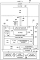
Figure 2 is an illustration of a block diagram of an ultrasonic fluid measurement probe with an ultrasonically welded base cap in accordance with an illustrative embodiment; -
Figure 3 is an illustration of an exploded perspective view of a base assembly for an ultrasonic fluid measurement probe in accordance with an illustrative embodiment; -
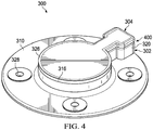
Figure 4 is an illustration of a perspective view of the base assembly for an ultrasonic fluid measurement probe ofFigure 3 with a cap ultrasonically welded to a base in accordance with an illustrative embodiment; and -
Figure 5 is an illustration of a flow chart of a method of making and using an ultrasonic fluid measurement probe in accordance with an illustrative embodiment. - The illustrative embodiments recognize and take into account different considerations. For example, the illustrative embodiments recognize and take into account that ultrasonic fuel measuring probes in fuel tanks on aircraft may be subject to extreme environmental conditions which may cause them to need to be repaired or replaced prematurely. An aircraft may need to be removed from service and maintenance personnel may need to perform a fuel tank entry when an ultrasonic fuel probe in an aircraft fuel tank needs to be repaired or replaced. Fuel tank entry by maintenance personnel to repair or replace a fuel probe requires draining and purging of the fuel tank. In many cases, repair or replacement of an ultrasonic fuel probe in the fuel tank of an aircraft may require up to two days of down time in which the aircraft is out of service. Such down time may be very costly to an airline or other operator of the aircraft.
- There may be relatively very many ultrasonic fuel measurement probes on an aircraft. For example, a Boeing 777-300ER passenger aircraft may use 76 ultrasonic fuel measurement probes in a fuel quantity indicating system. Illustrative embodiments recognize and take into account that reliability for commercial passenger aircraft and other aircraft may be improved and the cost of operating such aircraft reduced by reducing the need to repair or replace the ultrasonic fuel measurement probes that may be used for fuel gauging in such aircraft.
- Illustrative embodiments recognize and take into account that the polysulfide potting around the transducer in the base of a conventional ultrasonic fuel measurement probe may not perform as desired and thereby may allow fuel ingress into the foam pad area of the transducer. Fuel in the foam pad compromises the air space around the transducer and may result in the transducer being sensitive to reflections from the opposite direction it was intended to. This sensitivity to reflections from the opposite direction than intended may result in a reading from the ultrasonic transducer of a fuel height corresponding to the distance between the ultrasonic transducer and the bottom of the fuel tank on which the ultrasonic fuel measurement probe is placed. For example, a conventional ultrasonic fuel measurement probe in which an inconsistency in the polysulfide potting material results in fuel in the foam pad area around the ultrasonic transducer may provide a reading that indicates a fuel height of one or two centimeters regardless of the actual height of fuel in the fuel tank.
- Illustrative embodiments recognize and take into account that the polysulfide potting material in the base of an ultrasonic fuel measurement probe that is used to measure fuel height in an aircraft fuel tank may flex as the aircraft changes altitude from ground level to cruise altitude. Air trapped in the air space between the polysulfide potting material and the ultrasonic transducer remains at ground level pressure, therefore, the polysulfide potting material must endure a pressure difference between the pressure at ground level and the pressure at cruise level. For example, without limitation, the polysulfide potting material may be required to endure a pressure difference between sea level pressure in the air space on one side of the polysulfide potting material and the pressure at a cruising altitude near 40,000 feet above sea level on the other side of the polysulfide potting material. Such a pressure differential may cause the polysulfide potting material to expand under internal pressure from the air in the air space as the aircraft climbs from the ground to cruising altitude and then contract again as the aircraft descends from cruising altitude to the ground for landing. This cyclic mechanical stress may eventually compromise the seal of the polysulfide potting material. This cyclic mechanical stress also may cause tension in the wires that are soldered to the ultrasonic transducer disk, which may cause inconsistencies in the solder joints.
- Illustrative embodiments also recognize and take into account that various manufacturing issues may be associated with the use of polysulfide potting material in the base of an ultrasonic fluid measurement probe. For example, without limitation, contamination of the polysulfide potting material, achieving the appropriate ratio of materials that may be mixed together to form the polysulfide potting material, and achieving an acceptable consistency in the thickness of the polysulfide potting material deposited on the base of the probe may be some of the issues associated with the use of a polysulfide potting material in the base of a known ultrasonic fluid measurement probe.
- Illustrative embodiments recognize and take into account that sealing the transducer chamber in the base of an ultrasonic fluid measurement probe with a polysulfide potting material may be relatively messy and difficult to accomplish. For example, without limitation, the surfaces of the base that are to be adjacent to the polysulfide potting material may have to be bead blasted and cleaned thoroughly to allow the polysulfide potting material to adhere completely. The polysulfide material used for the potting in an ultrasonic fluid measurement probe for fuel gauging may be made from a two part compound that may require mixing in precise ratios for curing and that must be contamination free. Furthermore, deposition of the polysulfide potting material on the base of an ultrasonic fluid measurement probe to seal the transducer chamber may require expert skilled labor.
- Illustrative embodiments eliminate the foam pad and polysulfide potting material used in the base of a conventional ultrasonic fuel probe. In accordance with an illustrative embodiment, the cavity containing the ultrasonic transducer is sealed with a plastic cap that is ultrasonically welded to the base. The foam pad and polysulfide potting material used in conventional ultrasonic fuel probes are not required.
- Ultrasonic welding of a cap to seal the air space around the ultrasonic transducer of an ultrasonic fluid measurement probe may reduce or eliminate the various limitations of using polysulfide potting material in the base of an ultrasonic fluid measurement probe for such purpose. The strength and durability of the ultrasonically welded cap would not only eliminate the manufacturing issues associated with using a polysulfide potting material, but would also provide a significantly more robust design against environmental stresses. The result is a part that is more easily manufactured and more durable. An ultrasonic fuel measurement probe in accordance with an illustrative embodiment would not need to be repaired or replaced as often as a conventional ultrasonic fluid measurement probe using polysulfide potting material.
- Turning to
Figure 1 , an illustration of a block diagram of an ultrasonic fuel gauging system is depicted in accordance with an illustrative embodiment. For example, without limitation, ultrasonicfuel gauging system 100 may comprise part of a fuel quantity indicating system for indicating the amount of fuel infuel tanks 102 on an aircraft. - Ultrasonic
fuel gauging system 100 may be configured to perform a variety of functions. For example, without limitation, ultrasonicfuel gauging system 100 may be configured to measure fuel quantity infuel tanks 102, calculate the weight of fuel infuel tanks 102, measure the temperature of the fuel infuel tanks 102, control fueling operations, and show when there is water infuel tanks 102. Components offuel gauging system 100 may include ultrasonic sensor probes 104 for measuring fuel height,densitometers 106,temperature sensors 108, andwater detectors 110. Eachultrasonic sensor probe 104 may comprise base 122 andtube 124.Base 122 of eachultrasonic sensor probe 104 may comprise an ultrasonic transducer.Densitometers 106 measure the fuel density in eachfuel tank 102. - Appropriate wiring may be used to connect the ultrasonic fuel sensor probes 104 to fuel
quantity processor unit 112. Fuelquantity processor unit 112 may send a signal to eachultrasonic sensor probe 104 to find the fuel height. Theultrasonic sensor probe 104 sends a sound pulse frombase 122 at the bottom offuel tank 102 to the fuel surface intube 124 attached tobase 122. Fuelquantity processor unit 112 calculates the fuel height by measuring the time it takes for the pulse to give a reflection back to base 118. - Fuel
quantity processor unit 112 may use the fuel height to calculate the fuel volume. Fuelquantity processor unit 112 may then multiply fuel volume and density to calculate the fuel weight. Fuelquantity processor unit 112 may send fuel quantity data to integrated refuelpanel 114 and to display 116 on the flight deck of the aircraft. - The speed of the ultrasonic signal sent through the fuel in
ultrasonic sensor probe 104 is dependent on fuel density and temperature.Densitometer 106 in eachfuel tank 102 may be used to calculate fuel type during refueling. Some of ultrasonic sensor probes 104 may be calibration probes configured to calibrate the calculations of fuel height based on the information provided by other ultrasonic sensor probes 104 infuel tanks 102. - Turning to
Figure 2 , an illustration of a block diagram of an ultrasonic fluid measurement probe with an ultrasonically welded base cap is depicted in accordance with an illustrative embodiment.Probe 200 may be an ultrasonic fluid measurement probe that is used to determine the quantity offuel 202 infuel tank 204. In this case, probe 200 may be referred to as an ultrasonic fuel measurement probe or an ultrasonic fuel gauging probe. -
Probe 200 may be used to determine the quantity offuel 202 infuel tank 204 onaircraft 206.Aircraft 206 may comprise any appropriate type of vehicle that is configured to operate in the air. For example, without limitation,aircraft 206 may be a commercial passenger aircraft, a transportation aircraft, a military aircraft, a personal aviation aircraft, or any other type of aircraft configured to perform any appropriate operation or mission. - Alternatively, or in addition,
probe 200 may be used to determine the quantity offuel 202 infuel tank 204 in a vehicle other thanaircraft 206 or on any appropriate platform other than a vehicle. Alternatively, or in addition,probe 200 may be used to measure fluids other than fuels in containers or environments other than fuel tanks. For example, without limitation,probe 200 in accordance with an illustrative embodiment may be used to measure water in a water tank, fluid waste in a waste tank, or any other appropriate fluid in any other appropriate container or environment. -
Probe 200 may comprisebase assembly 208 andtube 210.Base assembly 208 may comprise base 212,ultrasonic transducer 214, andcap 216.Base 212 may comprisetransducer chamber 218 andflange portion 220.Base 212 may be made of any appropriate material and by any appropriate method. For example, without limitation,base 212 may be molded of a single piece of plastic. -
Transducer chamber 218 may be defined bytransducer chamber floor 222 andtransducer chamber walls 224 that extend fromtransducer chamber floor 222.Transducer chamber walls 224 may terminate attransducer chamber edge 226. -
Ultrasonic transducer 214 may be attached totransducer chamber floor 222 insidetransducer chamber 218. For example, without limitation,ultrasonic transducer 214 may comprise a piezoelectric transducer that is glued totransducer chamber floor 222 using any appropriate adhesive. Alternatively,ultrasonic transducer 214 may comprise any other appropriate transducer that may be attached totransducer chamber floor 222 using any other appropriate method, material, or structure. -
Base 212 may also comprisewiring channel 228.Wiring channel 228 may be in communication withtransducer chamber 218 such thatwires 230 may be run throughwiring channel 228 in totransducer chamber 218.Wiring channel 228 may be defined by wiringchannel floor 232 andwiring channel walls 234 that extend from wiringchannel floor 232.Wiring channel walls 234 may terminate at wiringchannel edge 236. -
Wires 230 may be run fromprocessor 238 throughwiring channel floor 232, throughwiring channel 228, intotransducer chamber 218, and be attached toultrasonic transducer 214.Wires 230 may be attached toultrasonic transducer 214 in any appropriate manner. For example, without limitation,wires 230 may be soldered toultrasonic transducer 214. -
Cap 216 may be attached totransducer chamber edge 226 to thereby enclosetransducer chamber 218 and formenclosed air space 240 betweenultrasonic transducer 214 andcap 216.Cap 216 also may be attached to wiringchannel edge 236 to enclosewiring channel 234. -
Cap 216 preferably may be ultrasonically welded totransducer chamber edge 226 and to wiringchannel edge 236.Cap 216 thus may be attached totransducer chamber edge 226 and to wiringchannel edge 236 byultrasonic weld 242. -
Cap 216 may be made of any appropriate material and by any appropriate method. For example,cap 216 may be made of anyappropriate plastic 244 by molding, by cuttingcap 216 from a piece ofplastic 244, or in any other appropriate manner. For example, without limitation,cap 216, may be made ofpolyphenylene sulphide 246. -
Tube 210 is attached tobase assembly 208 such that an ultrasonic signal generated byultrasonic transducer 214 is directed intotube 210.Tube 210 may be attached tobase assembly 208 in any appropriate manner.Fluid entry port 248 may be formed intube 210 at or near wheretube 210 is attached tobase assembly 208.Fluid entry port 248 may be configured in any appropriate manner to allow a fluid, such asfuel 202, to entertube 210 whenprobe 200 is placed in the fluid to measure the level of the fluid. -
Probe 200 may be used to measure the level offuel 202 infuel tank 204 by attachingbase assembly 208 ofprobe 200 tobottom 250 offuel tank 204 such thattube 210 extends upward frombottom 250 offuel tank 204.Fuel 202 may then entertube 210 throughfluid entry port 248 and rise to a level corresponding to the level offuel 202 infuel tank 204. For example, without limitation,probe 200 may be attached tobottom 250 offuel tank 204 by using anyappropriate fasteners 252 extending through mountingholes 254 inflange portion 220 ofbase 212 and intobottom 250 offuel tank 204. -
Processor 238 may comprisetransducer controller 256 andsignal processor 258.Transducer controller 256 may be configured to send a signal onwires 230 toultrasonic transducer 214 to causeultrasonic transducer 214 to generateultrasonic signal 260.Ultrasonic signal 260 is directed throughfuel 202 intube 210 and is reflected off ofsurface 262 offuel 202 intube 210. Reflectedultrasonic signal 264 is directed fromsurface 262 offuel 202 throughtube 210 back toultrasonic transducer 214.Ultrasonic transducer 214 sends a signal onwires 230 back toprocessor 238 in response to receiving reflectedultrasonic signal 264.Signal processor 258 inprocessor 238 may then process the signal received fromultrasonic transducer 214 in a known manner to providefuel level information 266 from which the level offuel 202 infuel tank 204 may be determined. - The illustration of ultrasonic
fluid measurement probe 200 inFigure 2 is not meant to imply physical or architectural limitations to the manner in which illustrative embodiments may be implemented. Other components, in addition to or in place of the ones illustrated, may be used. Some components may be optional. Also, the blocks are presented to illustrate some functional components. One or more of these blocks may be combined, divided, or combined and divided into different blocks when implemented in an illustrative embodiment. Turning toFigure 3 , an illustration of an exploded perspective view of a base assembly for an ultrasonic fluid measurement probe is depicted in accordance with an illustrative embodiment.Base assembly 300 may be an example of one implementation ofbase assembly 208 for ultrasonicfluid measurement probe 200 inFigure 2 . -
Base assembly 300 comprisesbase 302 andcap 304.Base 302 comprisestransducer chamber 306,wiring channel 308, andflange portion 310.Transducer chamber 306 is defined bytransducer chamber floor 312 andtransducer chamber walls 314.Transducer chamber walls 314 extend fromtransducer chamber floor 312 totransducer chamber edge 316. An ultrasonic transducer may be attached totransducer chamber floor 312 insidetransducer chamber 306. -
Wiring channel 308 is in communication withtransducer chamber 306 such that wires may be run throughwiring channel 308 intotransducer chamber 306.Wiring channel 308 is defined by wiringchannel floor 318 andwiring channel walls 320.Wiring channel walls 320 extend from wiringchannel floor 318 to wiringchannel edge 322. -
Cap 304 may be placed overtransducer chamber 306 andwiring channel 308, by movingcap 304 in the direction ofarrow 324, such thatedge 326 ofcap 304 is aligned withtransducer chamber edge 316 andwiring channel edge 322 to thereby enclosetransducer chamber 306 andwiring channel 308.Cap 304 may be attached totransducer chamber edge 316 andwiring channel edge 322 by ultrasonically weldingedge 326 ofcap 304 totransducer chamber edge 316 andwiring channel edge 322.Flange portion 310 extends radially outward fromtransducer chamber 306. Mountingholes 328 are formed inflange portion 310 such thatbase assembly 300 may be attached to a surface by extending appropriate fasteners through mountingholes 328 into the surface. - Turning to
Figure 4 , an illustration of a perspective view of thebase assembly 300 for an ultrasonic fluid measurement probe ofFigure 3 withcap 304 ultrasonically welded tobase 302 is depicted in accordance with an illustrative embodiment. An ultrasonic weld is thus formed at joint 400 betweencap 304 andbase 302. - Turning to
Figure 5 , an illustration of a flow chart of a method of making and using an ultrasonic fluid measurement probe is depicted in accordance with an illustrative embodiment.Process 500 may be an example of one method for making and using ultrasonicfluid measurement probe 200 inFigure 2 . -
Process 500 may begin with mounting an ultrasonic transducer in a transducer chamber in a base (operation 502). Wires may be run through a wiring channel in the base and connected to the ultrasonic transducer (operation 504). A cap may then be placed over the transducer chamber and the wiring channel on the base to form an enclosed air space between the cap and the transducer (operation 506). The cap may then be ultrasonically welded to the base to form a base assembly (operation 508). A tube may then be attached to the base assembly to form the ultrasonic fluid measurement probe (operation 510). - The ultrasonic fluid measurement probe may then be mounted in a fuel tank by attaching the base assembly to the fuel tank (operation 512). The wires from the ultrasonic transducer may then be connected to a processor (operation 514). The processor may then control the ultrasonic transducer to measure the level of fuel in the fuel tank (operation 516), with the process terminating thereafter.
- The flowcharts and block diagrams described herein illustrate the architecture, functionality, and operation of possible implementations of systems and methods according to various illustrative embodiments. In some alternative implementations, the operation noted in a block may occur out of the order noted in the figures. For example, the operations of two blocks shown in succession may be performed substantially concurrently, or the operations of the blocks may sometimes be performed in the reverse order, depending upon the functionality involved.
- The description of the different illustrative embodiments has been presented for purposes of illustration and description, and is not intended to be exhaustive or limited to the embodiments in the form disclosed. Many modifications and variations will be apparent to those of ordinary skill in the art. Further, different illustrative embodiments may provide different features as compared to other desirable embodiments. The embodiment or embodiments selected are chosen and described in order to best explain the principles of the embodiments, the practical application, and to enable others of ordinary skill in the art to understand the disclosure for various embodiments with various modifications as are suited to the particular use contemplated.
- The following numbered clauses are also disclosed:
- 1. An apparatus, comprising:
- a base comprising a transducer chamber, wherein the transducer chamber comprises a transducer chamber floor, a transducer chamber edge, and transducer chamber walls extending from the transducer chamber floor to the transducer chamber edge;
- an ultrasonic transducer attached to the transducer chamber floor; and
- a cap welded to the transducer chamber edge and that, along with the transducer chamber floor and the transducer chamber walls, encloses the transducer chamber to form an enclosed air space between the ultrasonic transducer and the cap.
- 2. The apparatus of clause 1, wherein the base further comprises:
- a flange portion, and
- a mounting hole in the flange portion.
- 3. The apparatus of clause 1 or 2, wherein the base further comprises:
- a wiring channel in communication with the transducer chamber, wherein the wiring channel comprises a wiring channel floor, a wiring channel edge, and wiring channel walls extending from the wiring channel floor to the wiring channel edge; and
- wherein the cap is welded to the wiring channel edge.
- 4. The apparatus of clause 3 further comprising wires attached to the ultrasonic transducer and extending from the ultrasonic transducer, through the transducer chamber, through the wiring channel, and through the wiring channel floor.
- 5. The apparatus of clause 4, wherein the wires are soldered to the ultrasonic transducer.
- 6. The apparatus of any preceding clause, wherein the ultrasonic transducer is a piezoelectric transducer.
- 7. The apparatus of any preceding clause, wherein the cap is made of plastic.
- 8. The apparatus of clause 7, wherein the cap is made of polyphenylene sulphide.
- 9. The apparatus of any preceding clause further comprising a tube attached to the base such that an ultrasonic signal generated by the ultrasonic transducer is directed into the tube.
- 10. The apparatus of clause 9, wherein the base is attached to an inside surface of a fuel tank on an aircraft such that the tube extends from the base into the fuel tank.
- 11. A method of enhancing reliability of an ultrasonic fluid measurement probe, comprising:
- generating an ultrasonic signal by an ultrasonic transducer in a transducer chamber in a base of the ultrasonic fluid measurement probe such that the ultrasonic signal is directed into a tube attached to the base of the ultrasonic fluid measurement probe, wherein the transducer chamber comprises a transducer chamber floor, transducer chamber walls, and a cap welded to an edge of the transducer chamber walls such that the cap, along with the transducer chamber floor and the transducer chamber walls, encloses the transducer chamber to form an enclosed air space; and
- detecting a reflection of the ultrasonic signal by the ultrasonic transducer.
- 12. The method of clause11 further comprising processing the detected reflection of the ultrasonic signal to determine a level of fluid in a container.
- 13. The method of clause 11 or 12 wherein processing the detected reflection of the ultrasonic signal to determine the level of fluid in a container comprises processing the detected reflection of the ultrasonic signal to determine a level of fuel in a fuel tank.
- 14. A method of enhancing reliability of an ultrasonic fluid measurement probe, comprising:
- attaching an ultrasonic transducer to a transducer chamber floor of a transducer chamber in a base, wherein the transducer chamber comprises the transducer chamber floor, a transducer chamber edge, and transducer chamber walls extending from the transducer chamber floor to the transducer chamber edge; and
- welding a cap to the transducer chamber edge such that the cap, along with the transducer chamber floor and the transducer chamber walls, encloses the transducer chamber to form an enclosed air space between the ultrasonic transducer and the cap.
- 15. The method of clause 14, wherein the base further comprises a wiring channel in communication with the transducer chamber, wherein the wiring channel comprises a wiring channel floor, a wiring channel edge, and wiring channel walls extending from the wiring channel floor to the wiring channel edge, and further comprising:
welding the cap to the wiring channel edge. - 16. The method of clause 15 further comprising:
- attaching wires to the ultrasonic transducer; and
- extending the wires from the ultrasonic transducer, through the transducer chamber, through the wiring channel, and through the wiring channel floor.
- 17. The method of any of clauses 14 to 16, wherein the cap is made of
plastic. - 18. The method of clause 17, wherein the cap is made of polyphenylene sulphide.
- 19. The method of clause 17, wherein welding the cap to the transducer chamber edge comprises ultrasonically welding the cap to the transducer chamber edge.
- 20. The method of any of clauses 14 to 19 further comprising attaching a
tube to the base such that an ultrasonic signal generated by the ultrasonic transducer is directed into the tube.
Claims (15)
- An apparatus, comprising:a base (212) comprising a transducer chamber (218),wherein
the transducer chamber (218) comprises a transducer chamber floor (222), a transducer chamber edge (226), and transducer chamber walls (224) extending from the transducer chamber floor (222) to the transducer chamber edge (226);an ultrasonic transducer (214) attached to the transducer chamber floor (222); anda cap (216) welded to the transducer chamber edge (226)and
that, along with the transducer chamber floor (222) and the transducer chamber walls (224), encloses the transducer chamber (218) to form an enclosed air space (240) between the ultrasonic transducer (214) and the cap (216). - The apparatus of claim 1, wherein the base (212) further comprises:a flange portion (220), anda mounting hole (254) in the flange portion (220).
- The apparatus of claim 1 or claim 2, wherein the base (212) further comprises:a wiring channel (228) in communication with the transducer chamber (218), wherein the wiring channel (228) comprises a wiring channel floor (232), a wiring channel edge (236), and wiring channel walls (234) extending from the wiring channel floor (232) to the wiring channel edge (236); andwherein the cap (216) is welded to the wiring channel edge (236).
- The apparatus of claim 3 further comprising wires (230) attached to the ultrasonic transducer (214) and extending from the ultrasonic transducer (214), through the transducer chamber (218), through the wiring channel (228), and through the wiring channel floor (232).
- The apparatus of claim 4, wherein the wires (230) are soldered to the ultrasonic transducer (214).
- The apparatus of any preceding claim wherein the ultrasonic transducer (214) is a piezoelectric transducer.
- The apparatus of any preceding claim wherein the cap (216) is made of plastic (244).
- The apparatus of claim 7, wherein the cap (216) is made of polyphenylene sulphide (246).
- The apparatus of any preceding claim further comprising a tube (210) attached to the base (212) such that an ultrasonic signal (260) generated by the ultrasonic transducer (214) is directed into the tube (210).
- The apparatus of claim 9, wherein the base (212) is attached to an inside surface of a fuel tank (204) on an aircraft (206) such that the tube (210) extends from the base (212) into the fuel tank (204).
- A method of enhancing reliability of an ultrasonic fluid measurement probe (202), comprising:attaching an ultrasonic transducer (214) to a transducer chamber floor (222) of a transducer chamber (218) in a base (212), wherein the transducer chamber (218) comprises the transducer chamber floor (222), a transducer chamber edge (226), and transducer chamber walls (224) extending from the transducer chamber floor (222) to the transducer chamber edge (226); andwelding a cap (216) to the transducer chamber edge (226) such that the cap (216), along with the transducer chamber floor (222) and the transducer chamber walls (224), encloses the transducer chamber (218) to form an enclosed air space (240) between the ultrasonic transducer (214) and the cap (216) .
- The method of claim 11, wherein the base (212) further comprises a wiring channel (228) in communication with the transducer chamber (218), wherein the wiring channel (228) comprises a wiring channel floor (232), a wiring channel edge (236), and wiring channel walls (234) extending from the wiring channel floor (232) to the wiring channel edge (236), and further comprising:welding the cap (216) to the wiring channel edge (236).
- The method of claim 12 further comprising:attaching wires (230) to the ultrasonic transducer (214); andextending the wires (230) from the ultrasonic transducer (214), through the transducer chamber (218), through the wiring channel (228), and through the wiring channel floor 232.
- The method of any of claims 11 to 13 wherein the cap (216) is made of
Plastic (244). - The method of any of claims 11 to 14 further comprising attaching a tube
(210) to the base (212) such that an ultrasonic signal (260) generated by the ultrasonic transducer (214) is directed into the tube (210).
Applications Claiming Priority (1)
| Application Number | Priority Date | Filing Date | Title |
|---|---|---|---|
| US15/833,129 US10955279B2 (en) | 2017-12-06 | 2017-12-06 | Ultrasonic fluid measurement probe with ultrasonically welded base cap |
Publications (2)
| Publication Number | Publication Date |
|---|---|
| EP3495785A1 true EP3495785A1 (en) | 2019-06-12 |
| EP3495785B1 EP3495785B1 (en) | 2022-02-02 |
Family
ID=64650172
Family Applications (1)
| Application Number | Title | Priority Date | Filing Date |
|---|---|---|---|
| EP18210595.7A Active EP3495785B1 (en) | 2017-12-06 | 2018-12-05 | Ultrasonic fluid measurement probe with ultrasonically welded base cap |
Country Status (4)
| Country | Link |
|---|---|
| US (1) | US10955279B2 (en) |
| EP (1) | EP3495785B1 (en) |
| CN (1) | CN109883492B (en) |
| CA (1) | CA3016214C (en) |
Families Citing this family (1)
| Publication number | Priority date | Publication date | Assignee | Title |
|---|---|---|---|---|
| US20240401996A1 (en) * | 2023-06-05 | 2024-12-05 | Tendo Technologies Inc. | Device, system, and method for fluid mass determination |
Citations (4)
| Publication number | Priority date | Publication date | Assignee | Title |
|---|---|---|---|---|
| US5410518A (en) * | 1993-11-12 | 1995-04-25 | Simmonds Precision Product, Inc. | Ultrasonic transducer assembly for measuring liquid level |
| US8893559B2 (en) * | 2010-04-12 | 2014-11-25 | Miitors Aps | Ultrasonic consumption meter with locking mechanism |
| US20160041024A1 (en) * | 2014-08-11 | 2016-02-11 | Ssi Technologies, Inc. | Through-wall tank ultrasonic transducer |
| US20160116324A1 (en) * | 2014-10-28 | 2016-04-28 | Schmitt Industries, Inc. | Mobile ultrasonic fuel detection system |
Family Cites Families (21)
| Publication number | Priority date | Publication date | Assignee | Title |
|---|---|---|---|---|
| US4637463A (en) * | 1984-08-02 | 1987-01-20 | Mccoy James N | Echo ranging gun |
| WO1992009749A1 (en) * | 1990-11-30 | 1992-06-11 | Tech-Scan Technologies Ltd. | Surface separator and dispersion apparatus |
| US5295120A (en) | 1990-12-26 | 1994-03-15 | Westinghouse Electric Corp. | Hermetically sealed ultrasonic transducer system |
| US5148700A (en) * | 1991-11-12 | 1992-09-22 | Entech Design, Inc. | Apparatus and method for locating sediment in a container |
| US6516661B1 (en) | 1999-01-28 | 2003-02-11 | Simmonds Precision Products, Inc. | Volume measurement system and method for volume element counting |
| US6799820B1 (en) * | 1999-05-20 | 2004-10-05 | Seiko Epson Corporation | Liquid container having a liquid detecting device |
| US7225670B2 (en) * | 2000-05-18 | 2007-06-05 | Seiko Epson Corporation | Mounting structure, module, and liquid container |
| DK1679196T3 (en) * | 2000-06-15 | 2008-08-25 | Seiko Epson Corp | Liquid filling process, liquid container and process for making it |
| US7900505B2 (en) * | 2000-09-25 | 2011-03-08 | Labcyte Inc. | Acoustic assessment of fluids in a plurality of reservoirs |
| DE20122896U1 (en) * | 2001-09-14 | 2009-07-16 | Sick Ag | Sensor and device for measuring the flow velocity and / or the flow of a fluid |
| US7717544B2 (en) * | 2004-10-01 | 2010-05-18 | Labcyte Inc. | Method for acoustically ejecting a droplet of fluid from a reservoir by an acoustic fluid ejection apparatus |
| US7036363B2 (en) * | 2003-07-03 | 2006-05-02 | Pathfinder Energy Services, Inc. | Acoustic sensor for downhole measurement tool |
| CN101648460B (en) * | 2004-11-15 | 2011-06-29 | 精工爱普生株式会社 | Liquid sensing device and liquid container equipped with the liquid sensing device |
| DE102005011049B4 (en) * | 2005-03-08 | 2010-09-23 | Eurocopter Deutschland Gmbh | Fuel level measuring device |
| EP1863644A1 (en) * | 2005-03-31 | 2007-12-12 | Seiko Epson Corporation | Container having liquid detecting function, and sensor unit |
| DE102009046147A1 (en) * | 2009-10-29 | 2011-05-05 | Robert Bosch Gmbh | Ultrasonic transducer for use in a fluid medium |
| DE102009046148A1 (en) * | 2009-10-29 | 2011-05-05 | Robert Bosch Gmbh | Ultrasonic transducer for use in a fluid medium |
| DE102010000967A1 (en) * | 2010-01-18 | 2011-07-21 | Robert Bosch GmbH, 70469 | Ultrasonic transducer for use in a fluid medium |
| EP2758753B1 (en) * | 2011-09-23 | 2016-02-24 | Kamstrup A/S | Flow meter with protruding transducers |
| TW201415057A (en) | 2012-10-08 | 2014-04-16 | Tung Thih Electronic Co Ltd | Embedded ultrasonic transducer device and assembling method thereof |
| WO2018013857A1 (en) * | 2016-07-13 | 2018-01-18 | Rain Bird Corporation | Flow sensor |
-
2017
- 2017-12-06 US US15/833,129 patent/US10955279B2/en active Active
-
2018
- 2018-08-30 CA CA3016214A patent/CA3016214C/en active Active
- 2018-10-22 CN CN201811227622.2A patent/CN109883492B/en active Active
- 2018-12-05 EP EP18210595.7A patent/EP3495785B1/en active Active
Patent Citations (4)
| Publication number | Priority date | Publication date | Assignee | Title |
|---|---|---|---|---|
| US5410518A (en) * | 1993-11-12 | 1995-04-25 | Simmonds Precision Product, Inc. | Ultrasonic transducer assembly for measuring liquid level |
| US8893559B2 (en) * | 2010-04-12 | 2014-11-25 | Miitors Aps | Ultrasonic consumption meter with locking mechanism |
| US20160041024A1 (en) * | 2014-08-11 | 2016-02-11 | Ssi Technologies, Inc. | Through-wall tank ultrasonic transducer |
| US20160116324A1 (en) * | 2014-10-28 | 2016-04-28 | Schmitt Industries, Inc. | Mobile ultrasonic fuel detection system |
Also Published As
| Publication number | Publication date |
|---|---|
| CA3016214A1 (en) | 2019-06-06 |
| EP3495785B1 (en) | 2022-02-02 |
| CN109883492A (en) | 2019-06-14 |
| CN109883492B (en) | 2023-07-04 |
| US10955279B2 (en) | 2021-03-23 |
| BR102018075096A2 (en) | 2019-06-25 |
| CA3016214C (en) | 2023-01-24 |
| US20190170559A1 (en) | 2019-06-06 |
Similar Documents
| Publication | Publication Date | Title |
|---|---|---|
| US10935408B2 (en) | System and method for acoustic container volume calibration | |
| JP3699138B2 (en) | Elastic wave detector | |
| US4815323A (en) | Ultrasonic fuel quantity gauging system | |
| US5309763A (en) | Liquid-level gauging | |
| US9395230B2 (en) | Fill level measurement system and method for determining a fill level | |
| CN102798435B (en) | For determining the Apparatus and method for of dielectric attribute and container feature | |
| US20100018309A1 (en) | Fluid level measuring method and system therefor | |
| US20010010171A1 (en) | Quantity Gauging | |
| EP3220175B1 (en) | Optically interfaced fluid density sensor | |
| US20090019929A1 (en) | Ultrasonic fluid measurement method | |
| WO2020180673A1 (en) | Universal liquid level sensing | |
| CA3016214C (en) | Ultrasonic fluid measurement probe with ultrasonically welded base cap | |
| CN109870216B (en) | Ultrasonic fluid measurement calibration probe | |
| US5922958A (en) | Acoustic channel for contaminant detection on a surface | |
| CN103620353A (en) | Device for measuring characteristics in a urea tank | |
| GB2412734A (en) | Measurement of fluid level and density with acoustic transducers | |
| BR102018075096B1 (en) | Ultrasonic Fluid Measurement Probe and Methods for Improving the Reliability of an Ultrasonic Fluid Measurement Probe | |
| RU2421692C1 (en) | Level gauge for liquid in tank | |
| CN119422331A (en) | Containers and level measurement systems for pressurized liquid gases | |
| WO2006134358A1 (en) | Acoustic wave sensor for sensing fluid level | |
| JPH01313720A (en) | Liquid level measuring method by ultrasonic echo and flow velocity measuring method and thickness measuring method for liquid layer, and ultrasonic transducer used for these methods | |
| RU2502957C2 (en) | Level-flow meter for liquid in tank |
Legal Events
| Date | Code | Title | Description |
|---|---|---|---|
| PUAI | Public reference made under article 153(3) epc to a published international application that has entered the european phase |
Free format text: ORIGINAL CODE: 0009012 |
|
| STAA | Information on the status of an ep patent application or granted ep patent |
Free format text: STATUS: REQUEST FOR EXAMINATION WAS MADE |
|
| 17P | Request for examination filed |
Effective date: 20181205 |
|
| AK | Designated contracting states |
Kind code of ref document: A1 Designated state(s): AL AT BE BG CH CY CZ DE DK EE ES FI FR GB GR HR HU IE IS IT LI LT LU LV MC MK MT NL NO PL PT RO RS SE SI SK SM TR |
|
| AX | Request for extension of the european patent |
Extension state: BA ME |
|
| STAA | Information on the status of an ep patent application or granted ep patent |
Free format text: STATUS: EXAMINATION IS IN PROGRESS |
|
| 17Q | First examination report despatched |
Effective date: 20200317 |
|
| GRAP | Despatch of communication of intention to grant a patent |
Free format text: ORIGINAL CODE: EPIDOSNIGR1 |
|
| STAA | Information on the status of an ep patent application or granted ep patent |
Free format text: STATUS: GRANT OF PATENT IS INTENDED |
|
| INTG | Intention to grant announced |
Effective date: 20210208 |
|
| GRAJ | Information related to disapproval of communication of intention to grant by the applicant or resumption of examination proceedings by the epo deleted |
Free format text: ORIGINAL CODE: EPIDOSDIGR1 |
|
| STAA | Information on the status of an ep patent application or granted ep patent |
Free format text: STATUS: EXAMINATION IS IN PROGRESS |
|
| INTC | Intention to grant announced (deleted) | ||
| GRAP | Despatch of communication of intention to grant a patent |
Free format text: ORIGINAL CODE: EPIDOSNIGR1 |
|
| STAA | Information on the status of an ep patent application or granted ep patent |
Free format text: STATUS: GRANT OF PATENT IS INTENDED |
|
| INTG | Intention to grant announced |
Effective date: 20210802 |
|
| GRAS | Grant fee paid |
Free format text: ORIGINAL CODE: EPIDOSNIGR3 |
|
| GRAA | (expected) grant |
Free format text: ORIGINAL CODE: 0009210 |
|
| STAA | Information on the status of an ep patent application or granted ep patent |
Free format text: STATUS: THE PATENT HAS BEEN GRANTED |
|
| AK | Designated contracting states |
Kind code of ref document: B1 Designated state(s): AL AT BE BG CH CY CZ DE DK EE ES FI FR GB GR HR HU IE IS IT LI LT LU LV MC MK MT NL NO PL PT RO RS SE SI SK SM TR |
|
| REG | Reference to a national code |
Ref country code: GB Ref legal event code: FG4D |
|
| REG | Reference to a national code |
Ref country code: CH Ref legal event code: EP Ref country code: AT Ref legal event code: REF Ref document number: 1466696 Country of ref document: AT Kind code of ref document: T Effective date: 20220215 |
|
| REG | Reference to a national code |
Ref country code: DE Ref legal event code: R096 Ref document number: 602018030350 Country of ref document: DE |
|
| REG | Reference to a national code |
Ref country code: IE Ref legal event code: FG4D |
|
| REG | Reference to a national code |
Ref country code: LT Ref legal event code: MG9D |
|
| REG | Reference to a national code |
Ref country code: NL Ref legal event code: MP Effective date: 20220202 |
|
| REG | Reference to a national code |
Ref country code: AT Ref legal event code: MK05 Ref document number: 1466696 Country of ref document: AT Kind code of ref document: T Effective date: 20220202 |
|
| PG25 | Lapsed in a contracting state [announced via postgrant information from national office to epo] |
Ref country code: SE Free format text: LAPSE BECAUSE OF FAILURE TO SUBMIT A TRANSLATION OF THE DESCRIPTION OR TO PAY THE FEE WITHIN THE PRESCRIBED TIME-LIMIT Effective date: 20220202 Ref country code: RS Free format text: LAPSE BECAUSE OF FAILURE TO SUBMIT A TRANSLATION OF THE DESCRIPTION OR TO PAY THE FEE WITHIN THE PRESCRIBED TIME-LIMIT Effective date: 20220202 Ref country code: PT Free format text: LAPSE BECAUSE OF FAILURE TO SUBMIT A TRANSLATION OF THE DESCRIPTION OR TO PAY THE FEE WITHIN THE PRESCRIBED TIME-LIMIT Effective date: 20220602 Ref country code: NO Free format text: LAPSE BECAUSE OF FAILURE TO SUBMIT A TRANSLATION OF THE DESCRIPTION OR TO PAY THE FEE WITHIN THE PRESCRIBED TIME-LIMIT Effective date: 20220502 Ref country code: NL Free format text: LAPSE BECAUSE OF FAILURE TO SUBMIT A TRANSLATION OF THE DESCRIPTION OR TO PAY THE FEE WITHIN THE PRESCRIBED TIME-LIMIT Effective date: 20220202 Ref country code: LT Free format text: LAPSE BECAUSE OF FAILURE TO SUBMIT A TRANSLATION OF THE DESCRIPTION OR TO PAY THE FEE WITHIN THE PRESCRIBED TIME-LIMIT Effective date: 20220202 Ref country code: HR Free format text: LAPSE BECAUSE OF FAILURE TO SUBMIT A TRANSLATION OF THE DESCRIPTION OR TO PAY THE FEE WITHIN THE PRESCRIBED TIME-LIMIT Effective date: 20220202 Ref country code: ES Free format text: LAPSE BECAUSE OF FAILURE TO SUBMIT A TRANSLATION OF THE DESCRIPTION OR TO PAY THE FEE WITHIN THE PRESCRIBED TIME-LIMIT Effective date: 20220202 Ref country code: BG Free format text: LAPSE BECAUSE OF FAILURE TO SUBMIT A TRANSLATION OF THE DESCRIPTION OR TO PAY THE FEE WITHIN THE PRESCRIBED TIME-LIMIT Effective date: 20220502 |
|
| PG25 | Lapsed in a contracting state [announced via postgrant information from national office to epo] |
Ref country code: PL Free format text: LAPSE BECAUSE OF FAILURE TO SUBMIT A TRANSLATION OF THE DESCRIPTION OR TO PAY THE FEE WITHIN THE PRESCRIBED TIME-LIMIT Effective date: 20220202 Ref country code: LV Free format text: LAPSE BECAUSE OF FAILURE TO SUBMIT A TRANSLATION OF THE DESCRIPTION OR TO PAY THE FEE WITHIN THE PRESCRIBED TIME-LIMIT Effective date: 20220202 Ref country code: GR Free format text: LAPSE BECAUSE OF FAILURE TO SUBMIT A TRANSLATION OF THE DESCRIPTION OR TO PAY THE FEE WITHIN THE PRESCRIBED TIME-LIMIT Effective date: 20220503 Ref country code: FI Free format text: LAPSE BECAUSE OF FAILURE TO SUBMIT A TRANSLATION OF THE DESCRIPTION OR TO PAY THE FEE WITHIN THE PRESCRIBED TIME-LIMIT Effective date: 20220202 Ref country code: AT Free format text: LAPSE BECAUSE OF FAILURE TO SUBMIT A TRANSLATION OF THE DESCRIPTION OR TO PAY THE FEE WITHIN THE PRESCRIBED TIME-LIMIT Effective date: 20220202 |
|
| PG25 | Lapsed in a contracting state [announced via postgrant information from national office to epo] |
Ref country code: IS Free format text: LAPSE BECAUSE OF FAILURE TO SUBMIT A TRANSLATION OF THE DESCRIPTION OR TO PAY THE FEE WITHIN THE PRESCRIBED TIME-LIMIT Effective date: 20220602 |
|
| PG25 | Lapsed in a contracting state [announced via postgrant information from national office to epo] |
Ref country code: SM Free format text: LAPSE BECAUSE OF FAILURE TO SUBMIT A TRANSLATION OF THE DESCRIPTION OR TO PAY THE FEE WITHIN THE PRESCRIBED TIME-LIMIT Effective date: 20220202 Ref country code: SK Free format text: LAPSE BECAUSE OF FAILURE TO SUBMIT A TRANSLATION OF THE DESCRIPTION OR TO PAY THE FEE WITHIN THE PRESCRIBED TIME-LIMIT Effective date: 20220202 Ref country code: RO Free format text: LAPSE BECAUSE OF FAILURE TO SUBMIT A TRANSLATION OF THE DESCRIPTION OR TO PAY THE FEE WITHIN THE PRESCRIBED TIME-LIMIT Effective date: 20220202 Ref country code: EE Free format text: LAPSE BECAUSE OF FAILURE TO SUBMIT A TRANSLATION OF THE DESCRIPTION OR TO PAY THE FEE WITHIN THE PRESCRIBED TIME-LIMIT Effective date: 20220202 Ref country code: DK Free format text: LAPSE BECAUSE OF FAILURE TO SUBMIT A TRANSLATION OF THE DESCRIPTION OR TO PAY THE FEE WITHIN THE PRESCRIBED TIME-LIMIT Effective date: 20220202 Ref country code: CZ Free format text: LAPSE BECAUSE OF FAILURE TO SUBMIT A TRANSLATION OF THE DESCRIPTION OR TO PAY THE FEE WITHIN THE PRESCRIBED TIME-LIMIT Effective date: 20220202 |
|
| REG | Reference to a national code |
Ref country code: DE Ref legal event code: R097 Ref document number: 602018030350 Country of ref document: DE |
|
| PG25 | Lapsed in a contracting state [announced via postgrant information from national office to epo] |
Ref country code: AL Free format text: LAPSE BECAUSE OF FAILURE TO SUBMIT A TRANSLATION OF THE DESCRIPTION OR TO PAY THE FEE WITHIN THE PRESCRIBED TIME-LIMIT Effective date: 20220202 |
|
| PLBE | No opposition filed within time limit |
Free format text: ORIGINAL CODE: 0009261 |
|
| STAA | Information on the status of an ep patent application or granted ep patent |
Free format text: STATUS: NO OPPOSITION FILED WITHIN TIME LIMIT |
|
| 26N | No opposition filed |
Effective date: 20221103 |
|
| PG25 | Lapsed in a contracting state [announced via postgrant information from national office to epo] |
Ref country code: SI Free format text: LAPSE BECAUSE OF FAILURE TO SUBMIT A TRANSLATION OF THE DESCRIPTION OR TO PAY THE FEE WITHIN THE PRESCRIBED TIME-LIMIT Effective date: 20220202 |
|
| P01 | Opt-out of the competence of the unified patent court (upc) registered |
Effective date: 20230516 |
|
| PG25 | Lapsed in a contracting state [announced via postgrant information from national office to epo] |
Ref country code: IT Free format text: LAPSE BECAUSE OF FAILURE TO SUBMIT A TRANSLATION OF THE DESCRIPTION OR TO PAY THE FEE WITHIN THE PRESCRIBED TIME-LIMIT Effective date: 20220202 |
|
| REG | Reference to a national code |
Ref country code: CH Ref legal event code: PL |
|
| REG | Reference to a national code |
Ref country code: BE Ref legal event code: MM Effective date: 20221231 |
|
| PG25 | Lapsed in a contracting state [announced via postgrant information from national office to epo] |
Ref country code: LU Free format text: LAPSE BECAUSE OF NON-PAYMENT OF DUE FEES Effective date: 20221205 |
|
| PG25 | Lapsed in a contracting state [announced via postgrant information from national office to epo] |
Ref country code: LI Free format text: LAPSE BECAUSE OF NON-PAYMENT OF DUE FEES Effective date: 20221231 Ref country code: IE Free format text: LAPSE BECAUSE OF NON-PAYMENT OF DUE FEES Effective date: 20221205 Ref country code: CH Free format text: LAPSE BECAUSE OF NON-PAYMENT OF DUE FEES Effective date: 20221231 |
|
| PG25 | Lapsed in a contracting state [announced via postgrant information from national office to epo] |
Ref country code: BE Free format text: LAPSE BECAUSE OF NON-PAYMENT OF DUE FEES Effective date: 20221231 |
|
| PG25 | Lapsed in a contracting state [announced via postgrant information from national office to epo] |
Ref country code: HU Free format text: LAPSE BECAUSE OF FAILURE TO SUBMIT A TRANSLATION OF THE DESCRIPTION OR TO PAY THE FEE WITHIN THE PRESCRIBED TIME-LIMIT; INVALID AB INITIO Effective date: 20181205 |
|
| PG25 | Lapsed in a contracting state [announced via postgrant information from national office to epo] |
Ref country code: CY Free format text: LAPSE BECAUSE OF FAILURE TO SUBMIT A TRANSLATION OF THE DESCRIPTION OR TO PAY THE FEE WITHIN THE PRESCRIBED TIME-LIMIT Effective date: 20220202 |
|
| PG25 | Lapsed in a contracting state [announced via postgrant information from national office to epo] |
Ref country code: MK Free format text: LAPSE BECAUSE OF FAILURE TO SUBMIT A TRANSLATION OF THE DESCRIPTION OR TO PAY THE FEE WITHIN THE PRESCRIBED TIME-LIMIT Effective date: 20220202 |
|
| PG25 | Lapsed in a contracting state [announced via postgrant information from national office to epo] |
Ref country code: MC Free format text: LAPSE BECAUSE OF FAILURE TO SUBMIT A TRANSLATION OF THE DESCRIPTION OR TO PAY THE FEE WITHIN THE PRESCRIBED TIME-LIMIT Effective date: 20220202 |
|
| PG25 | Lapsed in a contracting state [announced via postgrant information from national office to epo] |
Ref country code: TR Free format text: LAPSE BECAUSE OF FAILURE TO SUBMIT A TRANSLATION OF THE DESCRIPTION OR TO PAY THE FEE WITHIN THE PRESCRIBED TIME-LIMIT Effective date: 20220202 Ref country code: MC Free format text: LAPSE BECAUSE OF FAILURE TO SUBMIT A TRANSLATION OF THE DESCRIPTION OR TO PAY THE FEE WITHIN THE PRESCRIBED TIME-LIMIT Effective date: 20220202 |
|
| PG25 | Lapsed in a contracting state [announced via postgrant information from national office to epo] |
Ref country code: MT Free format text: LAPSE BECAUSE OF FAILURE TO SUBMIT A TRANSLATION OF THE DESCRIPTION OR TO PAY THE FEE WITHIN THE PRESCRIBED TIME-LIMIT Effective date: 20220202 |
|
| PGFP | Annual fee paid to national office [announced via postgrant information from national office to epo] |
Ref country code: GB Payment date: 20251229 Year of fee payment: 8 |
|
| PGFP | Annual fee paid to national office [announced via postgrant information from national office to epo] |
Ref country code: FR Payment date: 20251226 Year of fee payment: 8 |
|
| PGFP | Annual fee paid to national office [announced via postgrant information from national office to epo] |
Ref country code: DE Payment date: 20251229 Year of fee payment: 8 |