EP3495746A1 - Compressor unit and outdoor unit provided therewith - Google Patents
Compressor unit and outdoor unit provided therewith Download PDFInfo
- Publication number
- EP3495746A1 EP3495746A1 EP17880364.9A EP17880364A EP3495746A1 EP 3495746 A1 EP3495746 A1 EP 3495746A1 EP 17880364 A EP17880364 A EP 17880364A EP 3495746 A1 EP3495746 A1 EP 3495746A1
- Authority
- EP
- European Patent Office
- Prior art keywords
- compressor
- accumulator
- oil return
- refrigerant
- return pipe
- Prior art date
- Legal status (The legal status is an assumption and is not a legal conclusion. Google has not performed a legal analysis and makes no representation as to the accuracy of the status listed.)
- Withdrawn
Links
Images


Classifications
-
- F—MECHANICAL ENGINEERING; LIGHTING; HEATING; WEAPONS; BLASTING
- F25—REFRIGERATION OR COOLING; COMBINED HEATING AND REFRIGERATION SYSTEMS; HEAT PUMP SYSTEMS; MANUFACTURE OR STORAGE OF ICE; LIQUEFACTION SOLIDIFICATION OF GASES
- F25B—REFRIGERATION MACHINES, PLANTS OR SYSTEMS; COMBINED HEATING AND REFRIGERATION SYSTEMS; HEAT PUMP SYSTEMS
- F25B31/00—Compressor arrangements
- F25B31/002—Lubrication
- F25B31/004—Lubrication oil recirculating arrangements
-
- F—MECHANICAL ENGINEERING; LIGHTING; HEATING; WEAPONS; BLASTING
- F24—HEATING; RANGES; VENTILATING
- F24F—AIR-CONDITIONING; AIR-HUMIDIFICATION; VENTILATION; USE OF AIR CURRENTS FOR SCREENING
- F24F1/00—Room units for air-conditioning, e.g. separate or self-contained units or units receiving primary air from a central station
- F24F1/06—Separate outdoor units, e.g. outdoor unit to be linked to a separate room comprising a compressor and a heat exchanger
- F24F1/08—Compressors specially adapted for separate outdoor units
- F24F1/10—Arrangement or mounting thereof
-
- F—MECHANICAL ENGINEERING; LIGHTING; HEATING; WEAPONS; BLASTING
- F24—HEATING; RANGES; VENTILATING
- F24F—AIR-CONDITIONING; AIR-HUMIDIFICATION; VENTILATION; USE OF AIR CURRENTS FOR SCREENING
- F24F1/00—Room units for air-conditioning, e.g. separate or self-contained units or units receiving primary air from a central station
- F24F1/06—Separate outdoor units, e.g. outdoor unit to be linked to a separate room comprising a compressor and a heat exchanger
- F24F1/26—Refrigerant piping
- F24F1/30—Refrigerant piping for use inside the separate outdoor units
-
- F—MECHANICAL ENGINEERING; LIGHTING; HEATING; WEAPONS; BLASTING
- F25—REFRIGERATION OR COOLING; COMBINED HEATING AND REFRIGERATION SYSTEMS; HEAT PUMP SYSTEMS; MANUFACTURE OR STORAGE OF ICE; LIQUEFACTION SOLIDIFICATION OF GASES
- F25B—REFRIGERATION MACHINES, PLANTS OR SYSTEMS; COMBINED HEATING AND REFRIGERATION SYSTEMS; HEAT PUMP SYSTEMS
- F25B43/00—Arrangements for separating or purifying gases or liquids; Arrangements for vaporising the residuum of liquid refrigerant, e.g. by heat
- F25B43/006—Accumulators
-
- F—MECHANICAL ENGINEERING; LIGHTING; HEATING; WEAPONS; BLASTING
- F25—REFRIGERATION OR COOLING; COMBINED HEATING AND REFRIGERATION SYSTEMS; HEAT PUMP SYSTEMS; MANUFACTURE OR STORAGE OF ICE; LIQUEFACTION SOLIDIFICATION OF GASES
- F25B—REFRIGERATION MACHINES, PLANTS OR SYSTEMS; COMBINED HEATING AND REFRIGERATION SYSTEMS; HEAT PUMP SYSTEMS
- F25B43/00—Arrangements for separating or purifying gases or liquids; Arrangements for vaporising the residuum of liquid refrigerant, e.g. by heat
- F25B43/02—Arrangements for separating or purifying gases or liquids; Arrangements for vaporising the residuum of liquid refrigerant, e.g. by heat for separating lubricants from the refrigerant
-
- F—MECHANICAL ENGINEERING; LIGHTING; HEATING; WEAPONS; BLASTING
- F25—REFRIGERATION OR COOLING; COMBINED HEATING AND REFRIGERATION SYSTEMS; HEAT PUMP SYSTEMS; MANUFACTURE OR STORAGE OF ICE; LIQUEFACTION SOLIDIFICATION OF GASES
- F25B—REFRIGERATION MACHINES, PLANTS OR SYSTEMS; COMBINED HEATING AND REFRIGERATION SYSTEMS; HEAT PUMP SYSTEMS
- F25B2500/00—Problems to be solved
- F25B2500/13—Vibrations
-
- F—MECHANICAL ENGINEERING; LIGHTING; HEATING; WEAPONS; BLASTING
- F25—REFRIGERATION OR COOLING; COMBINED HEATING AND REFRIGERATION SYSTEMS; HEAT PUMP SYSTEMS; MANUFACTURE OR STORAGE OF ICE; LIQUEFACTION SOLIDIFICATION OF GASES
- F25B—REFRIGERATION MACHINES, PLANTS OR SYSTEMS; COMBINED HEATING AND REFRIGERATION SYSTEMS; HEAT PUMP SYSTEMS
- F25B2500/00—Problems to be solved
- F25B2500/16—Lubrication
-
- F—MECHANICAL ENGINEERING; LIGHTING; HEATING; WEAPONS; BLASTING
- F25—REFRIGERATION OR COOLING; COMBINED HEATING AND REFRIGERATION SYSTEMS; HEAT PUMP SYSTEMS; MANUFACTURE OR STORAGE OF ICE; LIQUEFACTION SOLIDIFICATION OF GASES
- F25B—REFRIGERATION MACHINES, PLANTS OR SYSTEMS; COMBINED HEATING AND REFRIGERATION SYSTEMS; HEAT PUMP SYSTEMS
- F25B2500/00—Problems to be solved
- F25B2500/28—Means for preventing liquid refrigerant entering into the compressor
Definitions
- the compressor is a vibration source since the electric motor is provided. Therefore, vibration from the compressor is transmitted to the oil return pipe connected between the accumulator and a compressor side.
- vibration from a compressor for example, a compressor having a high rotation speed which reaches over 130 rps to 200 rps, is not negligible.
- the present invention is devised in view of such circumstances, and an object thereof is to provide a compressor unit that reduces the stress of an oil return pipe connecting an accumulator to the compressor and an outdoor unit including the compressor unit.
- the compressor unit and the outdoor unit including the compressor unit of the present invention adopt the following means.
- the bent portion is formed in the oil return pipe below the capillary portion, stress concentrates on the bent portion.
- vibration to be caused in the bent portion is suppressed, and thus the stress of the pipe can be reduced.
Landscapes
- Engineering & Computer Science (AREA)
- Mechanical Engineering (AREA)
- General Engineering & Computer Science (AREA)
- Chemical & Material Sciences (AREA)
- Physics & Mathematics (AREA)
- Thermal Sciences (AREA)
- Analytical Chemistry (AREA)
- Power Engineering (AREA)
- Combustion & Propulsion (AREA)
- Other Air-Conditioning Systems (AREA)
Abstract
Description
- The present invention relates to a compressor unit including an accumulator and an outdoor unit including the compressor unit.
- An outdoor unit of an air conditioner is provided with a compressor that compresses a refrigerant. In the compressor, a compression portion such as a scroll part is driven by an electric motor, and a refrigerant sucked from a suction pipe is compressed.
- An accumulator for separating a refrigerant returning to the compressor into a gas refrigerant and a liquid refrigerant is connected to the suction pipe. The gas refrigerant separated out by the accumulator passes the suction pipe and is led to the compressor. An oil return pipe that returns a lubricant with the liquid refrigerant, which is separated out and is stored, to the compressor is provided on a bottom portion of the accumulator (refer to PTL 1).
- [PTL 1] Japanese Unexamined Utility Model Registration Application Publication No.
60-182678 Fig. 1 ) - The compressor is a vibration source since the electric motor is provided. Therefore, vibration from the compressor is transmitted to the oil return pipe connected between the accumulator and a compressor side. In particular, as a result of examination made by the present inventor or the like, it is found that vibration from a compressor, for example, a compressor having a high rotation speed which reaches over 130 rps to 200 rps, is not negligible.
- When vibration is transmitted to the oil return pipe, stress caused in the oil return pipe becomes great. In a case where the oil return pipe is provided with a capillary portion having a winding shape, the vibration of the oil return pipe further becomes great since the weight concentrates on the capillary portion. Thus, there is a problem of an increase in the stress of the pipe around the capillary portion.
- The present invention is devised in view of such circumstances, and an object thereof is to provide a compressor unit that reduces the stress of an oil return pipe connecting an accumulator to the compressor and an outdoor unit including the compressor unit.
- To solve the problems, the compressor unit and the outdoor unit including the compressor unit of the present invention adopt the following means.
- According to an aspect of the present invention, there is provided a compressor unit including a compressor that compresses a refrigerant, an accumulator that separates the refrigerant to be led to the compressor into a gas refrigerant and a liquid refrigerant, a suction pipe that is provided between the compressor and the accumulator and leads the gas refrigerant separated out by the accumulator to the compressor, an oil return pipe that is connected between a bottom portion of the accumulator and the suction pipe, a capillary portion that is provided at a position in a middle of the oil return pipe and has a winding shape, and a fixing bracket that fixes the oil return pipe below the capillary portion to the accumulator.
- The liquid refrigerant separated out by the accumulator passes the oil return pipe with a lubricant so as to be led to the suction pipe, and returns to the compressor.
- The vibration of the compressor is transmitted to the oil return pipe via the suction pipe. Since the oil return pipe is provided with the capillary portion having a winding shape, there is a possibility that the capillary portion, which is heavy, greatly vibrates and increases the stress of the pipe around the capillary portion.
- Thus, the fixing bracket that fixes the oil return pipe below the capillary portion to the accumulator is provided. Accordingly, the vibration of the capillary portion can be suppressed, and the stress of the oil return pipe can be reduced.
- In the compressor unit according to the aspect of the present invention, a bent portion is formed in the oil return pipe below the capillary portion, and the fixing bracket is provided below the bent portion.
- In a case where the bent portion is formed in the oil return pipe below the capillary portion, stress concentrates on the bent portion. By providing the fixing bracket below the bent portion, vibration to be caused in the bent portion is suppressed, and thus the stress of the pipe can be reduced.
- In the compressor unit according to the aspect of the present invention, the accumulator includes the bottom portion having a substantially hemispherical shape and a cylindrical portion connected to a portion above the bottom portion, and the fixing bracket is fixed to a lower end of the cylindrical portion.
- The accumulator includes the substantially hemispherical bottom portion and the cylindrical portion connected to the bottom portion. In a case where the fixing bracket is fixed to the accumulator by welding or the like, construction is difficult since the bottom portion has a substantially hemispherical shape. Thus, the fixing bracket is fixed to the cylindrical portion.
- In addition, the oil return pipe can be fixed at a position separated downwards from the capillary portion by fixing the fixing bracket to the lower end of the cylindrical portion. Accordingly, the stress of the pipe around the capillary portion can be reduced.
- In the compressor unit according to the aspect of the present invention, an oil return pipe side fixing position where one end of the fixing bracket is fixed to the oil return pipe is lower than an accumulator side fixing position where the other end of the fixing bracket is fixed to the accumulator.
- The oil return pipe side fixing position where one end of the fixing bracket is fixed to the oil return pipe is lower than the accumulator side fixing position where the other end of the fixing bracket is fixed to the accumulator. Accordingly, stress to be caused in the oil return pipe below the capillary portion can be further reduced by making a distance from the capillary portion to the oil return pipe side fixing position long.
- According to another aspect of the present invention, there is provided an outdoor unit including the compressor unit and a casing that accommodates the compressor unit. Advantageous Effects of Invention
- The stress of the pipe can be reduced by the fixing bracket suppressing the vibration of the oil return pipe that connects the accumulator to the compressor.
-
-
Fig. 1 is a diagram showing a refrigerant circuit of an air conditioner according to a first embodiment of the present invention. -
Fig. 2 is a side view of a compressor unit according to the first embodiment. -
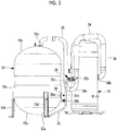
Fig. 3 is a side view of a compressor unit according to a second embodiment. - Hereinafter, embodiments according to the present invention will be described with reference to the drawings.
-
Fig. 1 is a refrigerant circuit diagram of a multi-split air conditioning system in which a plurality of indoor units are connected to one outdoor unit. There may be a plurality of outdoor units. - As shown in
Fig. 1 , in the multi-split air conditioning system 1, a plurality ofindoor units outdoor unit 2. The plurality ofindoor units liquid side pipe 5, which are connected to theoutdoor unit 2. - The
outdoor unit 2 includes an inverter-drivencompressor 10 that compresses a refrigerant, a four-way switching valve 12 that switches between refrigerant circulation directions, anoutdoor heat exchanger 13 that causes heat exchange between a refrigerant and outside air, asupercooling coil 14 that is integrally configured with theoutdoor heat exchanger 13, an outdoor expansion valve (EEVH) 15, areceiver 16 that stores a liquid refrigerant, asupercooling heat exchanger 17 that supercools a liquid refrigerant, an expansion valve for supercooling (EEVSC) 18 that controls a refrigerant amount to be divided for thesupercooling heat exchanger 17, anaccumulator 19 that separates a liquid out from a refrigerant gas to be sucked by thecompressor 10 and sucks only a gas into acompressor 10 side, a gasside operating valve 20, and a liquidside operating valve 21. - The
compressor 10 is rotatable at over 130 rps to 200 rps. Anoil separator 26 is connected to a discharge side of thecompressor 10 via adischarge pipe 25. In theoil separator 26, a mist-like lubricant (oil) in a compressed refrigerant is separated out from the refrigerant. The refrigerant from which the mist-like lubricant is separated out by theoil separator 26 is led to the four-way switching valve 12. - The
accumulator 19 is provided with anoil return pipe 35 that returns a liquid refrigerant separated by theaccumulator 19 to asuction pipe 34 with a lubricant. Theoil return pipe 35 is provided with acapillary portion 36. Thecapillary portion 36 is used as a fixed aperture, and reduces the pressures of the liquid refrigerant and the lubricant which pass therethrough. - The respective devices on an
outdoor unit 2 side are connected in turn via arefrigerant pipe 22, and configure a known outdoorside refrigerant circuit 23. In addition, theoutdoor unit 2 is provided with anoutdoor fan 24 that blows outside air with respect to theoutdoor heat exchanger 13. - The gas side pipe 4 and the
liquid side pipe 5 are refrigerant pipes which are respectively connected to the gasside operating valve 20 and the liquidside operating valve 21 of theoutdoor unit 2. At the time of mounting in the field, the lengths of the pipes are set as appropriate according to a distance between theoutdoor unit 2 and the plurality ofindoor units liquid side pipe 5, and an appropriate number ofindoor units - The
indoor units indoor heat exchanger 30 that cools or heats indoor air by causing heat exchange with a refrigerant and contributes to indoor air conditioning, an indoor expansion valve (EEVC) 31, anindoor fan 32 that circulates indoor air via theindoor heat exchanger 30, and anindoor controller 33. The indoor units are connected to the splitters 6 via gasside branch pipes side branch pipes 5A and 5B on an indoor side. - In the multi-split air conditioning system 1, heating operation is performed as follows.
- A high-temperature and high-pressure refrigerant gas, which is compressed and discharged by the
compressor 10, circulates to anoutdoor heat exchanger 13 side by means of the four-way switching valve 12, and exchanges heat with outside air blown to theoutdoor heat exchanger 13 by theoutdoor fan 24 so as to be condensed and liquefied. After being further cooled by the supercoolingcoil 14, the liquid refrigerant passes through theoutdoor expansion valve 15 and is temporarily stored inside thereceiver 16. - In the process of flowing to a liquid refrigerant pipe side via the
supercooling heat exchanger 17, the refrigerant of which a circulation amount is adjusted by thereceiver 16 is partially divided from a liquid refrigerant pipe, and exchanges heat with a refrigerant adiabatically expanded by the expansion valve for supercooling 18 to be given with a degree of supercooling. The liquid refrigerant is led from theoutdoor unit 2 to theliquid side pipe 5 via the liquidside operating valve 21, and is divided into the liquidside branch pipes 5A and 5B of theindoor units - The liquid refrigerant divided into the liquid
side branch pipes 5A and 5B flows into theindoor units indoor expansion valves 31, and forms a gas-liquid two-phase flow to flow into theindoor heat exchangers 30. Indoor air which is being circulated by theindoor fan 32 exchanges heat with a refrigerant in theindoor heat exchanger 30, and the indoor air is cooled and contributes to indoor cooling. Meanwhile, the refrigerant becomes a gas, reaches the splitters 6 via the gasside branch pipes - After the refrigerant gas which has joined in the gas side pipe 4 returns to the
outdoor unit 2 again and joins a refrigerant gas from the supercoolingheat exchanger 17 via the gasside operating valve 20 and the four-way switching valve 12, the refrigerant is introduced into theaccumulator 19. In theaccumulator 19, a liquid is separated out from the refrigerant gas, and only a gas is sucked into thecompressor 10. The refrigerant is again compressed by thecompressor 10, and cooling operation is performed by repeating such cycle. The liquid refrigerant separated out by theaccumulator 19 is stored in a bottom portion of theaccumulator 19, and is led to thesuction pipe 34 via theoil return pipe 35 with a lubricant. - On the other hand, heating operation is performed as follows.
- A high-temperature and high-pressure refrigerant gas which is compressed and discharged by the
compressor 10 circulates to a gasside operating valve 20 side via the four-way switching valve 12. The high-pressure gas refrigerant is led out from theoutdoor unit 2 via the gasside operating valve 20 and the gas side pipe 4, and is introduced into the plurality ofindoor units side branch pipes - The high-temperature and high-pressure refrigerant gas introduced in the
indoor units indoor heat exchangers 30 via theindoor fans 32, and accordingly the heated indoor air is blown out indoors and contributes to heating. On the other hand, a refrigerant which is condensed and liquefied by theindoor heat exchangers 30 reaches the splitters 6 via theindoor expansion valves 31 and the liquidside branch pipes 5A and 5B, joins a refrigerant from the other indoor unit, and returns to theoutdoor unit 2 via theliquid side pipe 5. At the time of heating, in theindoor units indoor expansion valves 31 is controlled via theindoor controller 33 such that a refrigerant outlet temperature or a degree of refrigerant supercooling of theindoor heat exchanger 30, which functions as a condenser, becomes a control target value. - After the refrigerant which has returned to the
outdoor unit 2 reaches thesupercooling heat exchanger 17 via the liquidside operating valve 21 and is supercooled as in the case of cooling, the refrigerant flows into thereceiver 16 and a circulation amount thereof is adjusted by being temporarily stored in the receiver. After being supplied to theoutdoor expansion valve 15 and being adiabatically expanded, the liquid refrigerant flows into theoutdoor heat exchanger 13 via the supercoolingcoil 14. - In the
outdoor heat exchanger 13, outside air blown from theoutdoor fan 24 exchanges heat with the refrigerant, and the refrigerant absorbs heat from the outside air to evaporate and become a gas. After joining a refrigerant gas from the supercoolingheat exchanger 17 via the four-way switching valve 12 from theoutdoor heat exchanger 13, the refrigerant is introduced into theaccumulator 19. In theaccumulator 19, a liquid is separated out from the refrigerant gas and only a gas is sucked into thecompressor 10. The gas is again compressed by thecompressor 10. Heating operation is performed by repeating such cycle. The liquid refrigerant separated out by theaccumulator 19 is stored in a bottom portion of theaccumulator 19, and is led to thesuction pipe 34 via theoil return pipe 35 with a lubricant. -
Fig. 2 illustrates a structure of the compressor unit including thecompressor 10 and theaccumulator 19 which are provided inside a casing of theoutdoor unit 2. - The
compressor 10 has a substantially cylindrical shape having an axis extending in a vertical direction. An electric motor (not illustrated) is accommodated in a lower portion of thecompressor 10, and a compression mechanism (not illustrated) such as a scroll part is accommodated in an upper portion of the compressor. - The
accumulator 19 having an axis in the vertical direction is erected, and has a cocoon shape formed with a substantiallyhemispherical bottom portion 19a, a substantially hemisphericalupper portion 19b, and acylindrical portion 19c sandwiched between thebottom portion 19a and theupper portion 19b. Theaccumulator 19 is fixed to a bottom plate (not illustrated) vialeg portions 19d. - An
upstream end 34a of thesuction pipe 34 is connected to a top portion of theaccumulator 19. Adownstream end 34b of thesuction pipe 34 is connected to thecompressor 10. After rising upwards from the top portion of theaccumulator 19, thesuction pipe 34 extends sideways and bends downwards. After being folded back in a U-shape at a folded-back portion 34c below, the suction pipe again rises upwards. Then, after rising upwards, thesuction pipe 34 extends sideways, again falls downwards, and is connected to a side portion of thecompressor 10 in the end. - The
oil return pipe 35 is provided between theaccumulator 19 and thesuction pipe 34, and is a pipe made of a metal such as stainless steel and a copper alloy. Anupstream end 35a of theoil return pipe 35 is connected to a lower end of thebottom portion 19a of theaccumulator 19. Adownstream end 35b of theoil return pipe 35 is connected at a vertically middle position of thecompressor 10 in the vicinity of the folded-back portion 34c at a lower portion of thesuction pipe 34. - The
capillary portion 36 is provided at a position in the middle of theoil return pipe 35, and has a winding shape which is obtained by winding a plurality of capillaries each having a diameter smaller than the diameter of theoil return pipe 35. Thecapillary portion 36 is provided in the vicinity of thedownstream end 35b of theoil return pipe 35 at a height position substantially the same as thedownstream end 35b. - The
oil return pipe 35 connected to an upstream side (the left inFig. 2 ) of thecapillary portion 36 has avertical portion 35d that extends downwards in the substantially vertical direction after being bent in a substantially L-shape at abent portion 35c. A fixingbracket 37 is fixed to thevertical portion 35d. - The fixing
bracket 37 is a sheet metal formed in a predetermined shape. An accumulatorside fixing position 37a of the fixingbracket 37 is provided by welding with respect to a side portion of a lower end of thecylindrical portion 19c of theaccumulator 19. The fixing bracket extends from the accumulatorside fixing position 37a in a horizontal direction. Therefore, an oil return pipeside fixing position 37b of the fixingbracket 37 is the same height position as the accumulatorside fixing position 37a, and is provided below thecapillary portion 36 and thebent portion 35c. - In the embodiment, the following operational effects are achieved.
- The vibration of the
compressor 10 is transmitted to theoil return pipe 35 via thesuction pipe 34. Since theoil return pipe 35 is provided with thecapillary portion 36 having a winding shape, there is a possibility that thecapillary portion 36, which is heavy, greatly vibrates and increases the stress of the pipe around thecapillary portion 36. On this respect, the fixingbracket 37 that fixes thevertical portion 35d of theoil return pipe 35 below thecapillary portion 36 to theaccumulator 19 is provided in the embodiment. Accordingly, the vibration of thecapillary portion 36 can be suppressed, and the stress of theoil return pipe 35 can be reduced. - Since the
bent portion 35c is formed in theoil return pipe 35 below thecapillary portion 36, stress concentrates on thebent portion 35c. By providing the fixingbracket 37 below thebent portion 35c, vibration to be caused in thebent portion 35c is suppressed, and thus the stress of the pipe can be reduced. - In a case where the fixing bracket is fixed to the
bottom portion 19a of theaccumulator 19 by welding or the like, construction is difficult since thebottom portion 19a has a substantially hemispherical shape. Thus, the fixingbracket 37 is fixed to thecylindrical portion 19c of theaccumulator 19 in the embodiment. - In addition, the
oil return pipe 35 can be fixed at the oil return pipeside fixing position 37b separated downwards from thecapillary portion 36 by fixing the fixingbracket 37 to the lower end of thecylindrical portion 19c. Accordingly, stress caused in the pipe around thecapillary portion 36 can be reduced. - Next, a second embodiment of the present invention will be described with reference to
Fig. 3 . The embodiment has a different fixing bracket configuration from that of the first embodiment, and other configurations are the same. Therefore, configurations that are the same as the first embodiment will be assigned with the same reference signs and description thereof will be omitted. Only differences will be described. - A fixing
bracket 38 has a shape that is curved in an up-and-down direction such that the heights of fixing positions of both ends are different from each other. That is, while an accumulatorside fixing position 38a of the fixingbracket 38 is provided on the lower end of thecylindrical portion 19c of theaccumulator 19 as in the first embodiment, an oil return pipeside fixing position 38b of the fixingbracket 38 is provided below the accumulatorside fixing position 38a. Accordingly, stress to be caused in theoil return pipe 35 below thecapillary portion 36 can be further reduced by making a distance from thecapillary portion 36 to the oil return pipeside fixing position 38b long. - Although the
compressor 10 is described as a compressor that is rotatable at over 130 rps to 200 rps in the respective embodiments described above, the present invention is not limited thereto. The compressor may be rotatable at a compressor rotation speed of 130 rps or lower, or at a compressor rotation speed of over 200 rps. -
- 1: multi-split air conditioning system
- 2: outdoor unit
- 3A, 3B: indoor unit
- 10: compressor
- 13: outdoor heat exchanger
- 19: accumulator
- 19a: bottom portion
- 19b: upper portion
- 19c: cylindrical portion
- 19d: leg portion
- 34: suction pipe
- 34a: upstream end
- 34b: downstream end
- 34c: folded-back portion
- 35: oil return pipe
- 35a: upstream end
- 35b: downstream end
- 35c: bent portion
- 35d: vertical portion
- 36: capillary portion
- 37: fixing bracket
- 37a: accumulator side fixing position
- 37b: oil return pipe side fixing position
- 38: fixing bracket
- 38a: accumulator side fixing position
- 38b: oil return pipe side fixing position
Claims (5)
- A compressor unit comprising:a compressor that compresses a refrigerant;an accumulator that separates the refrigerant to be led to the compressor into a gas refrigerant and a liquid refrigerant;a suction pipe that is provided between the compressor and the accumulator and leads the gas refrigerant separated out by the accumulator to the compressor;an oil return pipe that is connected between a bottom portion of the accumulator and the suction pipe;a capillary portion that is provided at a position in a middle of the oil return pipe and has a winding shape; anda fixing bracket that fixes the oil return pipe below the capillary portion to the accumulator.
- The compressor unit according to Claim 1,
wherein a bent portion is formed in the oil return pipe below the capillary portion, and
the fixing bracket is provided below the bent portion. - The compressor unit according to Claim 1 or 2,
wherein the accumulator includes the bottom portion having a substantially hemispherical shape and a cylindrical portion connected to a portion above the bottom portion, and
the fixing bracket is fixed to a lower end of the cylindrical portion. - The compressor unit according to any one of Claims 1 to 3, wherein an oil return pipe side fixing position where one end of the fixing bracket is fixed to the oil return pipe is lower than an accumulator side fixing position where the other end of the fixing bracket is fixed to the accumulator.
- An outdoor unit comprising:the compressor unit according to any one of Claims 1 to 4; anda casing that accommodates the compressor unit.
Applications Claiming Priority (2)
| Application Number | Priority Date | Filing Date | Title |
|---|---|---|---|
| JP2016241050A JP2018096608A (en) | 2016-12-13 | 2016-12-13 | Compressor unit and outdoor unit equipped with the same |
| PCT/JP2017/043384 WO2018110331A1 (en) | 2016-12-13 | 2017-12-04 | Compressor unit and outdoor unit provided therewith |
Publications (2)
| Publication Number | Publication Date |
|---|---|
| EP3495746A1 true EP3495746A1 (en) | 2019-06-12 |
| EP3495746A4 EP3495746A4 (en) | 2019-10-30 |
Family
ID=62558645
Family Applications (1)
| Application Number | Title | Priority Date | Filing Date |
|---|---|---|---|
| EP17880364.9A Withdrawn EP3495746A4 (en) | 2016-12-13 | 2017-12-04 | Compressor unit and outdoor unit provided therewith |
Country Status (3)
| Country | Link |
|---|---|
| EP (1) | EP3495746A4 (en) |
| JP (1) | JP2018096608A (en) |
| WO (1) | WO2018110331A1 (en) |
Families Citing this family (4)
| Publication number | Priority date | Publication date | Assignee | Title |
|---|---|---|---|---|
| JP7225001B2 (en) * | 2019-03-29 | 2023-02-20 | 三菱重工サーマルシステムズ株式会社 | air conditioner |
| JP7214533B2 (en) * | 2019-03-29 | 2023-01-30 | 三菱重工サーマルシステムズ株式会社 | air conditioner |
| JP2024011176A (en) * | 2022-07-14 | 2024-01-25 | 三菱重工業株式会社 | Compressor unit and refrigeration system |
| CN115540178B (en) * | 2022-08-18 | 2024-05-24 | 青岛海尔空调器有限总公司 | Air conditioning control method and air conditioner |
Family Cites Families (7)
| Publication number | Priority date | Publication date | Assignee | Title |
|---|---|---|---|---|
| JPH08189732A (en) * | 1995-01-09 | 1996-07-23 | Mitsubishi Heavy Ind Ltd | Refrigeration cycle |
| JP2008157504A (en) * | 2006-12-21 | 2008-07-10 | Itomic Kankyou System Co Ltd | Heat pump device and accumulator for heat pump |
| JP4814813B2 (en) * | 2007-02-21 | 2011-11-16 | ヤンマー株式会社 | Air conditioner |
| US20080314068A1 (en) * | 2007-06-21 | 2008-12-25 | Seok Hoon Jang | Outdoor unit of air conditioner |
| JP5520460B2 (en) * | 2008-08-25 | 2014-06-11 | 東芝キヤリア株式会社 | Method for manufacturing hermetic compressor and method for manufacturing refrigeration cycle apparatus |
| JP2011033211A (en) * | 2009-07-30 | 2011-02-17 | Sanyo Electric Co Ltd | Refrigerating device |
| JP2018100641A (en) * | 2016-12-21 | 2018-06-28 | 三菱重工サーマルシステムズ株式会社 | Compressor unit and outdoor unit including the same |
-
2016
- 2016-12-13 JP JP2016241050A patent/JP2018096608A/en active Pending
-
2017
- 2017-12-04 EP EP17880364.9A patent/EP3495746A4/en not_active Withdrawn
- 2017-12-04 WO PCT/JP2017/043384 patent/WO2018110331A1/en not_active Ceased
Also Published As
| Publication number | Publication date |
|---|---|
| EP3495746A4 (en) | 2019-10-30 |
| WO2018110331A1 (en) | 2018-06-21 |
| JP2018096608A (en) | 2018-06-21 |
Similar Documents
| Publication | Publication Date | Title |
|---|---|---|
| JP5398159B2 (en) | Oil return operation method for multi-type air conditioner and multi-type air conditioner | |
| EP1995536A1 (en) | Air conditioner and heat source unit | |
| EP2998656A1 (en) | Air conditioner | |
| JPWO2009040889A1 (en) | Air conditioner | |
| JP5354004B2 (en) | Air conditioner | |
| JP5452367B2 (en) | Gas-liquid separator and refrigeration cycle apparatus | |
| EP3502576A1 (en) | Compressor unit and outdoor unit provided therewith | |
| JP3864980B2 (en) | Air conditioner | |
| WO2018110331A1 (en) | Compressor unit and outdoor unit provided therewith | |
| EP3252401A1 (en) | Air-conditioning device | |
| EP3144606A1 (en) | Air conditioner | |
| EP2787314A1 (en) | Double-pipe heat exchanger and air conditioner using same | |
| EP3470674A1 (en) | Compressor unit and outdoor unit provided with same | |
| US11274863B2 (en) | Air conditioning system | |
| JP2015078777A (en) | Pipe assembly and refrigeration device | |
| JP2017141987A (en) | Refrigeration cycle equipment | |
| JP2006300371A (en) | Air conditioner | |
| EP3859230B1 (en) | Refrigeration cycle device | |
| EP4321820A1 (en) | Air conditioner | |
| EP4679002A1 (en) | Outdoor unit of air conditioning device, and air conditioning device | |
| JP2016121856A (en) | Refrigeration unit heat source unit | |
| US20250369671A1 (en) | Refrigeration cycle device | |
| WO2018110330A1 (en) | Compressor unit and outdoor unit provided therewith | |
| JP2018128226A (en) | Outdoor unit and its assembling method | |
| WO2018066025A1 (en) | Air conditioning device |
Legal Events
| Date | Code | Title | Description |
|---|---|---|---|
| PUAI | Public reference made under article 153(3) epc to a published international application that has entered the european phase |
Free format text: ORIGINAL CODE: 0009012 |
|
| 17P | Request for examination filed |
Effective date: 20190308 |
|
| AK | Designated contracting states |
Kind code of ref document: A1 Designated state(s): AL AT BE BG CH CY CZ DE DK EE ES FI FR GB GR HR HU IE IS IT LI LT LU LV MC MK MT NL NO PL PT RO RS SE SI SK SM TR |
|
| AX | Request for extension of the european patent |
Extension state: BA ME |
|
| STAA | Information on the status of an ep patent application or granted ep patent |
Free format text: STATUS: THE APPLICATION HAS BEEN WITHDRAWN |
|
| A4 | Supplementary search report drawn up and despatched |
Effective date: 20190930 |
|
| RIC1 | Information provided on ipc code assigned before grant |
Ipc: F24F 1/30 20110101AFI20190924BHEP Ipc: F25B 43/00 20060101ALI20190924BHEP Ipc: F25B 43/02 20060101ALI20190924BHEP Ipc: F25B 31/00 20060101ALI20190924BHEP |
|
| 18W | Application withdrawn |
Effective date: 20191010 |