EP3495687A1 - Worm gear reducer - Google Patents
Worm gear reducer Download PDFInfo
- Publication number
- EP3495687A1 EP3495687A1 EP17853066.3A EP17853066A EP3495687A1 EP 3495687 A1 EP3495687 A1 EP 3495687A1 EP 17853066 A EP17853066 A EP 17853066A EP 3495687 A1 EP3495687 A1 EP 3495687A1
- Authority
- EP
- European Patent Office
- Prior art keywords
- worm
- axial
- step surface
- teeth
- side step
- Prior art date
- Legal status (The legal status is an assumption and is not a legal conclusion. Google has not performed a legal analysis and makes no representation as to the accuracy of the status listed.)
- Granted
Links
Images




Classifications
-
- F—MECHANICAL ENGINEERING; LIGHTING; HEATING; WEAPONS; BLASTING
- F16—ENGINEERING ELEMENTS AND UNITS; GENERAL MEASURES FOR PRODUCING AND MAINTAINING EFFECTIVE FUNCTIONING OF MACHINES OR INSTALLATIONS; THERMAL INSULATION IN GENERAL
- F16H—GEARING
- F16H57/00—General details of gearing
- F16H57/02—Gearboxes; Mounting gearing therein
- F16H57/021—Shaft support structures, e.g. partition walls, bearing eyes, casing walls or covers with bearings
-
- B—PERFORMING OPERATIONS; TRANSPORTING
- B62—LAND VEHICLES FOR TRAVELLING OTHERWISE THAN ON RAILS
- B62D—MOTOR VEHICLES; TRAILERS
- B62D5/00—Power-assisted or power-driven steering
- B62D5/04—Power-assisted or power-driven steering electrical, e.g. using an electric servo-motor connected to, or forming part of, the steering gear
- B62D5/0403—Power-assisted or power-driven steering electrical, e.g. using an electric servo-motor connected to, or forming part of, the steering gear characterised by constructional features, e.g. common housing for motor and gear box
-
- B—PERFORMING OPERATIONS; TRANSPORTING
- B62—LAND VEHICLES FOR TRAVELLING OTHERWISE THAN ON RAILS
- B62D—MOTOR VEHICLES; TRAILERS
- B62D5/00—Power-assisted or power-driven steering
- B62D5/04—Power-assisted or power-driven steering electrical, e.g. using an electric servo-motor connected to, or forming part of, the steering gear
- B62D5/0409—Electric motor acting on the steering column
-
- F—MECHANICAL ENGINEERING; LIGHTING; HEATING; WEAPONS; BLASTING
- F16—ENGINEERING ELEMENTS AND UNITS; GENERAL MEASURES FOR PRODUCING AND MAINTAINING EFFECTIVE FUNCTIONING OF MACHINES OR INSTALLATIONS; THERMAL INSULATION IN GENERAL
- F16H—GEARING
- F16H1/00—Toothed gearings for conveying rotary motion
- F16H1/02—Toothed gearings for conveying rotary motion without gears having orbital motion
- F16H1/04—Toothed gearings for conveying rotary motion without gears having orbital motion involving only two intermeshing members
- F16H1/12—Toothed gearings for conveying rotary motion without gears having orbital motion involving only two intermeshing members with non-parallel axes
- F16H1/16—Toothed gearings for conveying rotary motion without gears having orbital motion involving only two intermeshing members with non-parallel axes comprising worm and worm-wheel
-
- F—MECHANICAL ENGINEERING; LIGHTING; HEATING; WEAPONS; BLASTING
- F16—ENGINEERING ELEMENTS AND UNITS; GENERAL MEASURES FOR PRODUCING AND MAINTAINING EFFECTIVE FUNCTIONING OF MACHINES OR INSTALLATIONS; THERMAL INSULATION IN GENERAL
- F16H—GEARING
- F16H57/00—General details of gearing
- F16H57/02—Gearboxes; Mounting gearing therein
- F16H57/031—Gearboxes; Mounting gearing therein characterised by covers or lids for gearboxes
-
- F—MECHANICAL ENGINEERING; LIGHTING; HEATING; WEAPONS; BLASTING
- F16—ENGINEERING ELEMENTS AND UNITS; GENERAL MEASURES FOR PRODUCING AND MAINTAINING EFFECTIVE FUNCTIONING OF MACHINES OR INSTALLATIONS; THERMAL INSULATION IN GENERAL
- F16H—GEARING
- F16H57/00—General details of gearing
- F16H57/02—Gearboxes; Mounting gearing therein
- F16H57/039—Gearboxes for accommodating worm gears
-
- F—MECHANICAL ENGINEERING; LIGHTING; HEATING; WEAPONS; BLASTING
- F16—ENGINEERING ELEMENTS AND UNITS; GENERAL MEASURES FOR PRODUCING AND MAINTAINING EFFECTIVE FUNCTIONING OF MACHINES OR INSTALLATIONS; THERMAL INSULATION IN GENERAL
- F16H—GEARING
- F16H57/00—General details of gearing
- F16H57/04—Features relating to lubrication or cooling or heating
- F16H57/0463—Grease lubrication; Drop-feed lubrication
- F16H57/0464—Grease lubrication
-
- F—MECHANICAL ENGINEERING; LIGHTING; HEATING; WEAPONS; BLASTING
- F16—ENGINEERING ELEMENTS AND UNITS; GENERAL MEASURES FOR PRODUCING AND MAINTAINING EFFECTIVE FUNCTIONING OF MACHINES OR INSTALLATIONS; THERMAL INSULATION IN GENERAL
- F16H—GEARING
- F16H57/00—General details of gearing
- F16H57/04—Features relating to lubrication or cooling or heating
- F16H57/048—Type of gearings to be lubricated, cooled or heated
- F16H57/0498—Worm gearings
-
- F—MECHANICAL ENGINEERING; LIGHTING; HEATING; WEAPONS; BLASTING
- F16—ENGINEERING ELEMENTS AND UNITS; GENERAL MEASURES FOR PRODUCING AND MAINTAINING EFFECTIVE FUNCTIONING OF MACHINES OR INSTALLATIONS; THERMAL INSULATION IN GENERAL
- F16H—GEARING
- F16H57/00—General details of gearing
- F16H57/02—Gearboxes; Mounting gearing therein
- F16H57/021—Shaft support structures, e.g. partition walls, bearing eyes, casing walls or covers with bearings
- F16H2057/0213—Support of worm gear shafts
-
- F—MECHANICAL ENGINEERING; LIGHTING; HEATING; WEAPONS; BLASTING
- F16—ENGINEERING ELEMENTS AND UNITS; GENERAL MEASURES FOR PRODUCING AND MAINTAINING EFFECTIVE FUNCTIONING OF MACHINES OR INSTALLATIONS; THERMAL INSULATION IN GENERAL
- F16H—GEARING
- F16H55/00—Elements with teeth or friction surfaces for conveying motion; Worms, pulleys or sheaves for gearing mechanisms
- F16H55/02—Toothed members; Worms
- F16H55/22—Toothed members; Worms for transmissions with crossing shafts, especially worms, worm-gears
- F16H55/24—Special devices for taking up backlash
Definitions
- the present invention relates to a worm reducer incorporated and used in, for example, an electric power steering device.
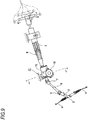
- Fig. 9 illustrates an example of a conventional structure of a steering device for an automobile.
- Rotation of a steering wheel 1 is transmitted to an input shaft 3 of a steering gear unit 2, and a pair of left and right tie rods 4 are pushed or pulled along with rotation of the input shaft 3 to apply a steering angle to front wheels.
- the steering wheel 1 is supported and fixed to a rear end portion of a steering shaft 5.
- the steering shaft 5 is rotatably supported to a cylindrical steering column 6 with being axially inserted in the steering column 6.
- a front end portion of the steering shaft 5 is connected to a rear end portion of an intermediate shaft 8 through a universal joint 7, and a front end portion of the intermediate shaft 8 is connected to the input shaft 3 through another universal joint 9.
- an electric power steering device for reducing a force required to operate the steering wheel 1 by using an electric motor 10 as an auxiliary power source.
- the electric power steering device includes a reducer.
- reducer there has been generally used a worm reducer having a large lead angle and reversibility in a transmission direction of power.
- Fig. 10 illustrates an example of a conventional structure of a worm reducer described in Japanese Patent No. 4381024 .
- the worm reducer 11 includes a housing 12, a worm wheel 13, and a worm 14.
- the housing 12 is supported and fixed to the electric motor 10 and includes a wheel accommodating portion 15 and a worm accommodating portion 16.
- a center axis of the worm accommodating portion 16 is arranged at a skew position with respect to a center axis of the wheel accommodating portion 15, and the worm accommodating portion 16 has an axially intermediate portion open to the wheel accommodating portion 15.
- the worm wheel 13 includes wheel teeth 17 on an outer circumferential surface.
- the worm wheel 13 is supported and fixed to a front side portion of the steering shaft 5 (see Fig. 9 ) coaxially with the steering shaft 5 which is rotatably supported inside the wheel accommodating portion 15.
- the worm 14 includes worm teeth 18 meshing with the wheel teeth 17 on the outer circumferential surface of the axial intermediate portion.
- worm 14 two positions in the axial direction interposing the worm teeth 18 are rotatably supported inside the worm accommodating portion 16 by a pair of rolling bearings 19a, 19b, such as a deep groove ball bearing.
- An output shaft of the electric motor 10 is connected to a proximal end portion (a left end portion in Fig. 10 ) of the worm 14. That is, the worm 14 can be rotationally driven by the electric motor 10.
- a distal end portion (a right end portion in Fig. 10 ) of the worm 14 is elastically pressed in the radial direction toward the worm wheel 13 (an upper side in Fig. 10 ). Accordingly, a backlash between the wheel teeth 17 and the worm teeth 18 is suppressed, and generation of harsh tooth rattling noise at a meshing portion between the wheel teeth 17 and the worm teeth 18 is prevented.
- the proximal end portion of the worm 14 is supported to allow slight swing with respect to the worm accommodating portion 16 via the rolling bearing 19a on the proximal end side among the pair of rolling bearings 19a, 19b.
- a pressing piece 20 is externally fitted to a distal end portion of the worm 14, and a coil spring 21 is provided between the pressing piece 20 and the worm accommodating portion 16.
- the distal end portion of the worm 14 is elastically pressed toward the worm wheel 13 (an upper side in Fig. 10 ) in a direction orthogonal to a center axis of the worm wheel 13 and a center axis of the worm 14 (an upper-lower direction in Fig. 10 ) via the pressing piece 20 by the coil spring 21.
- Patent Document 1 Japanese Patent No. 4381024
- the meshing portion between the wheel teeth 17 and the worm teeth 18 is lubricated with grease, but there is room of improvement in maintaining lubricity of the meshing portion for a long period of time. That is, when grease is pushed out from the meshing portion, the pushed grease moves in the axial direction of the worm 14 to escape from the meshing portion to enter the rolling bearings 19a, 19b. Accordingly, it is possible that the grease used for lubrication of the meshing portion may be reduced.
- an aspect of the present invention provides a structure of a worm reducer capable of maintaining lubricity of the meshing portion between wheel teeth and worm teeth for a long period of time.
- a worm reducer includes: a housing, worm wheel and a worm.
- the housing includes a wheel accommodating portion, and a worm accommodating portion which has a center axis arranged at a skew position with respect to a center axis of the wheel accommodating portion and which includes an axial intermediate portion open to the wheel accommodating portion.
- the worm wheel includes wheel teeth disposed on an outer circumferential surface and is rotatably supported inside the wheel accommodating portion.
- the worm includes worm teeth disposed on an outer circumferential surface to mesh with the wheel teeth and is rotatably supported inside the worm accommodating portion, wherein a proximal end portion of the worm is connected to a drive shaft such that torque can be transmitted.
- An inner circumferential surface of the worm accommodating portion includes a housing side step surface which faces a proximal end side in an axial direction of the worm, and
- An outer circumferential surface of the worm includes a worm side step surface which closely faces the housing side step surface in the axial direction at a portion axially deviated from a portion where the worm teeth are disposed.
- the housing side step surface and the worm side step surface may be parallel to each other.
- the housing side step surface may be provided around an entire circumference of the worm accommodating portion and the worm side step surface may be provided around an entire circumference of the worm.
- the worm side step surface may be provided on the outer circumferential surface of the worm at a portion on a proximal end side than the worm teeth in the axial direction of the worm and has an outer diameter larger than a tip diameter of the worm teeth.
- the worm side step surface may be provided on the outer circumferential surface of the worm at a portion on a distal end side than the worm teeth in the axial direction of the worm and has an outer diameter equal to or smaller than a tip diameter of the worm teeth.
- An axial interval between the worm side step surface and the housing side step surface may be shorter than a minimum value of an axial interval between a tooth bottom surface of a dummy tooth portion present at an end portion of the worm teeth on a proximal end side in the axial direction of the worm and a tooth tip surface of the wheel teeth.
- the worm is rotatably supported inside the worm accommodating portion by a bearing at least one position of two axial positions interposing the worm teeth.
- a bearing for example, a rolling bearing including an outer ring including an outer ring raceway on an inner circumferential surface, an inner ring including an inner ring raceway on an outer circumferential surface, and a plurality of rolling elements rotatably provided between the outer ring raceway and the inner ring raceway may be used.
- a radial ball bearing, a radial roller bearing, a radial taper roller bearing, or the like may be used.
- a sliding bearing may also be used as the bearing.
- the housing side step surface provided on the inner circumferential surface of the worm accommodating portion and the worm side step surface provided on the outer circumferential surface of the worm closely face each other. Therefore, due to a labyrinth effect occurring between the housing side step surface and the worm side step surface, grease pushed out from the meshing portion between the wheel teeth and the worm teeth can be prevented from moving in the axial direction of the worm and escaping from the meshing portion. Consequently, lubricity of the meshing portion can be maintained for a long period of time.
- FIGs. 1 to 4 illustrate a first example of an embodiment of the present invention.
- a worm reducer 11a of this embodiment includes a housing 12a, a worm wheel 13, and a worm 14, similarly to the worm reducer 11 having a conventional structure illustrated in Fig. 10 .
- the housing 12a is supported and fixed to an electric motor 10 (refer to Fig. 10 ) and includes a wheel accommodating portion 15 and a worm accommodating portion 16a.
- a center axis of the worm accommodating portion 16a is arranged at a skew position with respect to a center axis of the wheel accommodating portion 15, and an axial intermediate portion of the worm accommodating portion 16a opens to the wheel accommodating portion 15.
- a small-diameter portion 22 is provided on an inner circumferential surface of the axial intermediate portion of the worm accommodating portion 16a, and holding recesses 23a, 23b each having an inner diameter larger than that of the small-diameter portion 22 are provided on inner circumferential surfaces of both axial end portions of the worm accommodating portion 16a.
- a housing side step surface 24 which faces one axial side is provided over the entire circumference on another axial end portion (a left end portion in Fig. 1 ) of a connection portion between the holding recess 23a on the one axial side (right side in Fig. 1 ) and the small-diameter portion 22.
- a cylindrical surface portion 65 whose inner diameter does not change in the axial direction is provided at an intermediate portion of the connection portion between the holding recess 23a on the one axial side (right side in Fig. 1 ) and the small-diameter portion 22.
- the housing side step surface 24 is a partial conical surface inclined in a direction in which the inner diameter increases as proceeding toward the one axial side.
- the cylindrical surface portion 65 may be omitted.
- the housing 12a can be formed by casting iron-based metal having sufficient rigidity and durability, die cast molding a light alloy such as an aluminum-based alloy, injection molding a synthetic resin or the like.
- the one axial side refers to a side of the proximal end portion of the worm 14a rotatably supported on an inner side of the worm accommodating portion 16a, and the other axial side refers to the distal end side of the worm 14a.
- the worm wheel 13 includes wheel teeth 17 disposed on an outer circumferential surface thereof and is rotatably supported and fixed coaxially with a steering shaft 5 on a front side portion of the steering shaft 5 (see Fig. 9 ), which is a driven shaft rotatably supported on the inner side of the wheel accommodating portion 15.
- An axial intermediate portion of the worm 14a includes a medium-diameter portion 25 having an outer diameter larger than that of a portion adjacent to the other axial side, and worm teeth 18 are disposed on an outer circumferential surface of a portion ranging from one axial side portion to the other axial end edge of the medium-diameter portion 25.
- the outer circumferential surface of the worm 14a includes an outward flange portion 26 protruding radially outward over the entire circumference at a portion adjacent to one axial side of the medium-diameter portion 25, and a worm side step surface 27 is provided over the entire circumference on the other axial side surface of the outward flange portion 26. Therefore, the outer diameter of the worm side step surface 27 is larger than a tip diameter of the worm teeth 18.
- One axial end portion of the worm teeth 18 includes a dummy tooth portion 51 whose tooth height decreases as proceeding toward the one axial side and cannot properly mesh with the wheel teeth 17.
- the dummy tooth portion 51 is formed, for example, as follows when the worm 14a is formed. That is, in order to form the worm 14a, first, a stepped columnar member including the medium-diameter portion 25 at the axial intermediate portion, and the outward flange portion 26 at the portion adjacent to one axial side of the medium-diameter portion 25 is obtained by performing a cutting processing on a columnar metal material.
- a cutting edge of a milling cutter is pressed against the one axial side portion of the outer circumferential surface of the medium-diameter portion 25 of the stepped columnar member.
- the milling cutter and the stepped columnar member are rotated in the same direction and are relatively displaced in the axial direction, so that the worm teeth 18 are formed in a portion extending from the one axial side portion to the other axial end edge of the medium-diameter portion 25 to form the worm 14a.
- the one axial end portion of the worm teeth 18, which is a cutting start position by the milling cutter is formed with the dummy tooth portion 51 having a smaller tooth height as proceeding toward the one axial side.
- an outer diameter D 27 of the worm side step surface 27 is larger than an inner diameter of the housing side step surface 24, that is, an inner diameter d 22 of the small-diameter portion 22 of the worm accommodating portion 16a (D 27 > d 22 ).
- a labyrinth portion which is inclined in a direction toward a radially outer side as proceeding toward the one axial side is formed between the housing side step surface 24 and the worm side step surface 27.
- the other axial end of the labyrinth portion is connected to one end portion of a cylindrical space between the small-diameter portion 22 of the worm accommodating portion 16a and the outer circumferential surface of the worm teeth 18.
- the housing side step surface 24 and the worm side step surface 27 are parallel to each other. That is, the worm side step surface 27 is inclined in a direction in which the outer diameter increases as proceeding toward the one axial side to form a partial conical surface parallel to the housing side step surface 24.
- An axial interval L between the housing side step surface 24 and the worm side step surface 27 varies depending on an axial length, outer diameter, and the like of the worm 14a, and may be about 1 mm to 5 mm in a case of the worm reducer incorporated in an electric power steering device for a typical automobile.
- the axial interval L between the housing side step surface 24 and the worm side step surface 27 is shorter than a minimum value of an axial interval between a tooth bottom surface of the dummy tooth portion 51 and a tooth tip surface of the wheel teeth 17 and is shorter than an axial length of a fitting portion of a cover 42 (described later) to an opening portion of the holding recess 23b on the other axial side.
- the outer circumferential surface of the outward flange portion 26 is a cylindrical surface whose outer diameter does not change in the axial direction, and a radial gap is provided between the outer circumferential surface of the outward flange portion 26 and the cylindrical surface portion 65 of the worm accommodating portion 16a. That is, the inner diameter of the cylindrical surface portion 65 is larger than an outer diameter of the outer circumferential surface of the outward flange portion 26.
- the worm side step surface 27 may be formed on the outer circumferential surface of the outward flange portion 26 in the axial direction. That is, the outer circumferential surface of the outward flange portion 26 may be inclined along the axial direction in a direction in which the outer diameter increases as proceeding toward the one axial side and have a partial conical surface parallel to the housing side step surface 24.
- worm 14a two axial positions interposing the worm teeth 18 are rotatably supported inside the worm accommodating portion 16a by a pair of rolling bearings 19a, 19c, such as a deep-groove ball bearing in a state where the worm teeth 18 mesh with the wheel teeth 17.
- Grease is applied to the meshing portion between the wheel teeth 17 and the worm teeth 18.
- An inner ring of the rolling bearing 19a on the proximal end side (one axial side, right side in Fig. 1 ) is externally fitted and fixed by an interference fit to a bearing fitting portion 53a provided at a proximal end side portion of the worm 14a in a state where the other axial end surface of the inner ring abuts on the one axial side surface of the outward flange portion 26.
- the outer ring of the rolling bearing 19a on the proximal end side is internally fitted into the holding recess 23a on the one axial side.
- an inner ring of the rolling bearing 19c on a distal end side (the other axial side, left side in Fig. 1 ) is externally fitted to a bearing fitting portion 53b provided at a distal end portion of the worm 14a by an interference fit.
- An outer ring of the rolling bearing 19c on the distal end side is internally fitted and supported on the holding recess 23b on the other axial side via an elastic biasing mechanism 30.
- the elastic biasing mechanism 30 includes an outer holder 31, a bearing holder 32, a leaf spring 33, and a pair of wedge-shaped pieces 34.
- the outer holder 31 includes a holder main body 35 and a lid body 36 and is internally fitted and held in the holding recess 23b on the other axial side by clearance fit in a state where rotation is prohibited.
- the bearing holder 32 is internally fitted and held inside the outer holder 31 to be displaceable in a close/separate moving direction (an upper-lower direction in Fig. 1 to Fig. 2 ) A with respect to the worm wheel 13 which is a direction orthogonal to the center axis of the worm wheel 13 and the center axis of the worm 14a.
- a pair of notch portions 37 is provided at two positions of the other axial end edge of the bearing holder 32 which are substantially opposite in the radial direction.
- the leaf spring 33 is formed by bending a metal plate having elasticity into a partially cylindrical shape, and both end portions in the circumferential direction are engaged to the pair of notch portions 37.
- the rolling bearing 19c on the distal end side is biased in the radial direction by elasticity of the leaf spring 33 and is elastically pressed against the inner circumferential surface of the bearing holder 32.
- a pair of wedge-shaped pieces 34 is arranged to fill portions of an annular space existing between the inner circumferential surface of the holding recess 23b of the other axial side and the outer circumferential surface of the bearing holder 32 in two positions sandwiching an imaginary plane ⁇ including the center axis of the worm 14a and the meshing portion between the wheel teeth 17 and the worm teeth 18.
- the thickness of the pair of wedge-shaped pieces 34 in the radial direction increases in the circumferential direction from an end portion on a side farther from the meshing portion toward an end portion on a side closer to the meshing portion.
- a radius of curvature of the outer circumferential surface of the pair of wedge-shaped pieces 34 is the same as a radius of curvature of the inner circumferential surface of the holding recess 23b on the other axial side, and the radius of curvature of the inner circumferential surface of the pair of wedge-shaped pieces 34 is larger than the radius of curvature of the outer circumferential surface of the bearing holder 31.
- the pair of wedge-shaped pieces 34 are applied with elasticity in a direction away from the meshing portion in the circumferential direction by a torsion coil spring 38.
- the small-diameter cylindrical portion 39 of the bearing holder 31 is inserted into a coil portion 40 of a torsion coil spring 35, and a pair of arm portions 41 of the torsion coil spring 35 is pressed against an end surface on the side closer to the meshing portion among both end surfaces in the circumferential direction of the pair of wedge-shaped pieces 34.
- the distal end portion of the worm 14a is elastically biased to a side of the worm wheel 13 in a close/separate moving direction A with respect to the worm wheel 13, thereby suppressing backlash in the meshing portion.
- the cover 42 is press-fitted into the opening portion of the holding recess 23b, so that the opening portion is closed.
- the proximal end portion of the worm 14a is coupled to a distal end portion of an output shaft 52 of the electric motor 10 via a torque transmission joint 43 such that torque can be transmitted.
- the torque transmission joint 43 includes a driving-side transmission member 44, a driven-side transmission member 45, and a coupling 46.
- the driving-side transmission member 44 is configured into a substantially cylindrical shape and includes a driving-side concave-convex portion 47 in which concave portions and convex portions are alternately arranged over an entire outer circumferential surface between the other axial end portion to the intermediate portion.
- the driving-side transmission member 44 is externally fitted and fixed to the distal end portion of the output shaft 52 of the electric motor 10 by an interference fit.
- the driven-side transmission member 45 has a substantially cylindrical shape and includes a driven-side concave-convex portion 48 in which concave portions and convex portions are alternately arranged over an entire outer circumferential surface between one axial end portion to the intermediate portion.
- the driven-side transmission member 45 is externally fitted and fixed to a connecting shaft portion 49 provided on the proximal end portion of the worm 14a by an interference fit.
- the coupling 46 has a substantially cylindrical shape and includes a coupling-side concave-convex portion 50 in which the concave portions and the convex portions are alternately arranged over an entire inner circumferential surface.
- the height (height of each tooth) in the radial direction of the convex portions constituting the coupling-side concave-convex portion 50 is smaller at both axial end portions than the axial intermediate portion.
- a driving-side concave-convex portion 47 of the driving-side transmission member 44 is engaged to one axial half portion of the coupling-side concave-convex portion 50 such that torque can be transmitted.
- the distal end surface of the axial intermediate portion of each of the convex portions constituting the coupling-side concave-convex portion 50 is lightly pressed into a bottom surface of the other axial half portion of each of the concave portions constituting the driving-side concave-convex portion 47. That is, the distal end surface of the axial intermediate portion of each of the convex portions constituting the coupling-side concave-convex portion 50 and the bottom surface of the other axial half portion of each of the concave portions constituting the driving-side concave-convex portion 47 abut on each other with surface pressure to be slidable in the circumferential direction at the start of torque transmission between the output shaft 52 and the worm 14a.
- a radial gap is interposed between a distal end surface of one axial end portion of each of the convex portions constituting the coupling-side concave-convex portion 50 and a bottom surface of each of the concave portions of one axial half portion of each of the concave portions constituting the driving-side concave-convex portion 47, and between the bottom surface of each of the concave portions constituting the coupling-side concave-convex portion 50 and the distal end surface of each of the convex portions constituting the driving-side concave-convex portion 47, respectively.
- the driven-side concave-convex portion 48 of the driven-side transmission member 45 is engaged to the other axial half portion of the coupling-side concave-convex portion 50 such that torque can be transmitted.
- the distal end surface of the axial intermediate portion of each of the convex portions constituting the coupling-side concave-convex portion 50 is lightly pressed into the bottom surface of one axial half portion of each of the concave portions constituting the driven-side concave-convex portion 48.
- the distal end surface of the axial intermediate portion of the convex portion constituting the coupling-side concave-convex portion 50 and the bottom surface of one axial half portion of the concave portion constituting the driven-side concave-convex portion 48 abut on each other with surface pressure to be slidable in the circumferential direction at the start of torque transmission between the output shaft 52 and the worm 14a.
- a radial gap is interposed between a distal end surface of the other axial end portion of each of the convex portions constituting the coupling-side concave-convex portion 50 and a bottom surface of each of the concave portions of the other axial half portions of the concave portions constituting the driven-side concave-convex portion 48 and between the bottom surface of each of the concave portions constituting the coupling-side concave-convex portion 50 and the distal end surface of each of the convex portions constituting the driven-side concave-convex portion 48, respectively.
- the housing side step surface 24 provided on the inner circumferential surface of the worm accommodating portion 16a and the worm side step surface 27 provided on the outer circumferential surface of the worm 14a closely face each other. Therefore, due to a labyrinth effect occurring between the housing side step surface 24 and the worm side step surface 27, grease pushed out from the meshing portion between the wheel teeth 17 and the worm teeth 18 can be prevented from moving in the axial direction of the worm 14a and escaping from the meshing portion. Consequently, lubricity of the meshing portion can be maintained for a long period of time.
- the worm 14a may be displaced toward the other axial side.
- the worm side step surface 27 and the housing side step surface 24 collide with each other before the tooth bottom surface of the dummy tooth portion 51 interferes with the tooth tip surface of the wheel teeth 17 even if the worm 14a is displaced toward the other axial side.
- the interference between the tooth bottom surface of the dummy tooth portion 51 and the tooth tip surface of the wheel teeth 17 can be reliably prevented, and damage such as flaws on tooth surfaces of the worm teeth 18 and the wheel teeth 17 can be reliably prevented.
- the interval L is shorter than the axial length of the fitting portion of the cover 42 to the opening portion of the holding recess 23b on the other axial side, even when the worm 14a is displaced toward the other axial side, the cover 42 can be reliably prevented from falling off from the opening portion of the holding recess 23b on the other axial side. That is, even when the worm 14a is displaced toward the other axial side by the interval L, fitting of the cover 42 to the opening portion of the holding recess 23b is maintained.
- the worm side step surface 27 and the housing side step surface 24 are parallel to each other, the worm side step surface 27 and the housing side step surface 24 are brought into surface contact with each other when the worm side step surface 27 collides with the housing side step surface 24. Further, since the worm side step surface 27 is provided on a portion of the worm 14a which is adjacent to one axial side of the middle-diameter portion 25, the outer diameter of the worm side step surface 27 is relatively large. As a result, an abutment area between the worm side step surface 27 and the housing side step surface 24 can be made relatively large, and stress can be effectively prevented from being concentrated on an abutment portion between the worm side step surface 27 and the housing side step surface 24.
- the worm wheel 13 is rotatably supported in the wheel accommodating portion 15.
- the worm 14a is inserted into the inside of the worm accommodating portion 16a from one axial side opening portion of the worm accommodating portion 16a.
- the other axial end portion of the worm teeth 18 is brought to meshing with the wheel teeth 17.
- the worm wheel 13 is rotated in a state where the other axial end portion of the worm teeth 18 meshes with the wheel teeth 17, the worm 14a is further inserted (pushed) into the worm accommodating portion 16a.
- the elastic biasing mechanism 30 is inserted (installed) between the distal portion of the worm 14a and the holding recess 23b on the other axial side from the other axial side opening portion of the worm accommodating portion 16b. Thereafter, the cover 42 is press-fitted into the other axial side opening portion of the worm accommodating portion 16a.
- the elastic biasing mechanism 30 and the cover 42 may be installed inside the holding recess 23b on the other axial side.
- the interval L is shorter than the minimum value of the interval in the axial direction between the tooth bottom surface of the dummy tooth portion 51 and the tooth tip surface of the wheel teeth 17, and shorter than the axial length of the fitting portion of the cover 42 to the opening portion of the holding recess 23b on the other axial side, it is possible to reliably prevent an occurrence that the tooth bottom surface of the dummy tooth portion 51 interferes with the tooth tip surface of the wheel teeth 17 or that the cover 42 falls off, which may be caused by excessive pushing when the worm 14a is pushed to a predetermined position in the worm accommodating portion 16a.
- the rolling bearing 19a on the proximal end side is installed between the bearing fitting portion 53a of the worm 14a and the holding recess 23a on the one axial side.
- the output shaft 52 of the electric motor 10 is connected to the proximal end portion of the worm 14a via the torque transmission joint 43.
- a method of assembling the worm reducer 11a is not limited to the above-described method. That is, in a state where one or both of the pair of rolling bearings 19a, 19, and the elastic biasing mechanism 30 as necessary may be assembled to the worm 14a as a subassembly, the subassembly may be assembled inside the worm accommodating portion 16a.
- the elastic biasing mechanism 30 is provided between the holding recess 23b on the other axial side and the rolling bearing 19c on the distal end side, and the distal end portion of the worm 14a is elastically biased toward the side of the worm wheel 13 via the rolling bearing 19c on the distal end side.
- the pair of wedge-shaped pieces 34 constituting the elastic biasing mechanism 30 are provided to fill an annular space existing between the inner circumferential surface of the holding recess 23b on the other axial side and the outer circumferential surface of the bearing holder 32.
- the outer circumferential surface of the pair of wedge-shaped pieces 34 is in sliding contact with the inner circumferential surface of the holding recess 23b on the other axial side, and the inner circumferential surface of the pair of wedge-shaped pieces 34 is in sliding contact with the outer circumferential surface of the bearing holder 32.
- the output shaft 52 of the electric motor 10 and the worm 14a are coupled via the torque transmission joint 43 such that torque can be transmitted.
- occurrence of abnormal noise between the output shaft 52 and the worm 14a can be prevented, and torque transmission between the output shaft 52 and the worm 14a can be smoothly performed even if the center axes of the output shaft 52 and the worm 14a do not coincide with each other.
- the distal end surface of the axial intermediate portion having a large height in the radial direction of each of the convex portions constituting the coupling-side concave-convex portion 50 is lightly pressed into the bottom surface of the other axial half portion of each of the concave portions constituting the driving-side concave-convex portion 47 and the bottom surface of one axial half portion of each of the concave portions constituting the driven-side concave-convex portion 48.
- the distal end surface of the axial intermediate portion of each of the convex portions constituting the coupling-side concave-convex portion 50, the bottom surface of the other axial intermediate portion of each of the concave portions constituting the driving-side concave-convex portion 47, and the bottom surface of one axial half portion of each of the concave portions constituting the driven-side concave-convex portion 48 slide in the circumferential direction.
- the other axial half portion of the driving-side concave-convex portion 47 and one axial half portion of the driven-side concave-convex portion 48 are each engaged with both axial end portions of the coupling-side concave-convex portion 50 with a radial gap interposed therebetween, and a circumferential gap is interposed between the coupling-side concave-convex portion 50 and each of the driving-side concave-convex portion 47 and the driven-side concave-convex portion 48.
- the coupling 46 inclines with respect to at least one of shafts of the output shaft 52 and the worm 14a based on the presence of the radial gap and the circumferential gap. As a result, torque is smoothly transmitted between the output shaft 52 and the worm 14a.
- the housing side step surface and the worm side step surface which face each other are provided over the entire circumference.
- a discontinuous portion may be partially provided.
- the elastic biasing mechanism which elastically biases the distal end portion of the worm toward the worm wheel side and the torque transmission joint which couples the worm and the output shaft of the electric motor to enable torque transmission are not limited to the above embodiment, and various conventionally known structures may be employed.
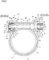
- Fig. 5 illustrates a second example of an embodiment of the present invention.
- a small-diameter portion 22a is provided at an axial intermediate portion of an inner circumferential surface of a worm accommodating portion 16b constituting a housing 12b, and the small-diameter portion 22a is provided with an inward flange portion 54 protruding radially inward on one axial end portion thereof.
- One axial side surface of the inward flange portion 54 is a partially-conical-surface-shaped housing side step surface 24a inclined in a direction in which an inner diameter increases as proceeding toward the one axial side, and the housing side step surface 24a closely faces a worm side step surface 27 provided on an outer circumferential surface of a worm 14a.
- a radial gap between a tooth tip surface of the worm teeth 18 of the worm 14a and the small-diameter portion 22a is easily obtained. Configuration and operation of other parts are similar to those of the above-described first embodiment.
- Fig. 6 illustrates a third example of an embodiment of the present invention.
- a small-diameter portion 22b is provided at an axial intermediate portion of an inner circumferential surface of a worm accommodating portion 16c constituting a housing 12c, and an inward flange portion 55 protruding radially inward is provided on the other axial end portion of the small-diameter portion 22b.
- One axial side surface of the inward flange portion 55 is a housing side step surface 24b.
- the housing side step surface 24b is a plane orthogonal to the axial direction of the worm accommodating portion 16b (a left-right direction in Fig. 6 ).
- the cylindrical surface portion 56 is provided with a worm side step surface 27a facing the other axial side at one axial end portion thereof.
- a step portion 66 having an outer diameter smaller than a tip diameter of the worm teeth 18 is provided at the other axial end portion of the medium-diameter portion 25a, and the cylindrical surface portion 56 and the step portion 66 are connected by the worm side step surface 27a.
- the step portion 66 may be omitted as long as the outer diameter of the worm side step surface 27a is equal to or smaller than the tip diameter of the worm teeth 18.
- the worm side step surface 27a and the housing side step surface 24b directly and closely face each other without any other member disposed therebetween.
- An axial interval between the housing side step surface 24b and the worm side step surface 27a is shorter than a minimum value of an axial interval between a tooth bottom surface of a dummy tooth portion 51 provided at one axial end portion of the worm teeth 18 and a tooth tip surface of the wheel teeth 17 and is shorter than an axial length of a fitting portion of a cover 42 to an opening portion of a holding recess 23b on the other axial side.
- a reduction in grease supplied for lubrication of the meshing portion can be prevented, which could occur in a case where grease pushed out from the meshing portion between the wheel teeth 17 and the worm teeth 18 largely moves in the axial direction of the worm 14b, escapes from the meshing portion and enters a rolling bearing 19c on a distal end side. Consequently, lubricity of the meshing portion can be maintained for a long period of time.
- the axial interval between the housing side step surface 24b and the worm side step surface 27a is shorter than a minimum value of the axial interval between the tooth bottom surface of the dummy tooth portion 51 and the tooth tip surface of the wheel teeth 17. Therefore, even when an impact load toward the other axial side is applied to the worm 14b such that the worm 14b is displaced toward the other axial side, the worm side step surface 27b and the housing side step surface 24b collide with each other before the tooth bottom surface of the dummy tooth portion 51 interferes with the tooth tip surface of the wheel teeth 17. As a result, interference between the tooth bottom surface of the dummy tooth portion 51 and the tooth tip surface of the wheel teeth 17 can be reliably prevented, and damage such as flaws on tooth surfaces of the worm teeth 18 and the wheel teeth 17 can be reliably prevented.
- the cover 42 can be reliably prevented from falling off the opening portion of the holding recess 23b on the other axial side even if the worm 14a is displaced toward the other axial side.
- Configuration and operation of other parts are similar to those of the above-described first and second embodiments.
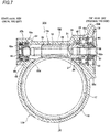
- Fig. 7 illustrates a fourth example of an embodiment of the present invention.
- a small-diameter portion 22 is provided on an inner circumferential surface of an axial intermediate portion of a worm accommodating portion 16d constituting a housing 12d, and holding recesses 23a, 23b having an inner diameter larger than that of a small-diameter portion 22 are provided on inner circumferential surfaces of both axial end portions of the worm accommodating portion 16d.
- a housing side step surface 24 which faces the one axial side is provided on the other axial end portion (left end portion in Fig. 7 ) of a connection portion between the holding recess 23a on the one axial side (right side in Fig. 7 ) and the small-diameter portion 22.
- the axial intermediate portion of the worm 14c includes a medium-diameter portion 25 having an outer diameter larger than that of a portion adjacent to the other axial side, and the worm teeth 18 are provided on an outer circumferential surface of a portion ranging from one axial side portion to the other axial end edge of the medium-diameter portion 25.
- the outward flange portion 26 protruding radially outward is provided on a portion adjacent to one axial side of the medium-diameter portion 25, and the worm side step surface 27 is provided on the other axial side surface of the outward flange portion 26.
- the worm side step surface 27 and the housing side step surface 24 directly and closely face each other without any other member interposed therebetween . Therefore, due to a labyrinth effect occurring between the housing side step surface 24 and the worm side step surface 27, grease pushed out from the meshing portion between the wheel teeth 17 and the worm teeth 18 can be prevented from moving in the axial direction of the worm 14c and escaping from the small-diameter portion 22 arranged around the meshing portion of the worm accommodating portion 16c to a side of the rolling bearing 19a on the proximal end side. Consequently, lubricity of the meshing portion can be maintained for a long period of time.
- the axial interval between the housing side step surface 24 and the worm side step surface 27 is shorter than a minimum value of the axial interval between a tooth bottom surface of the dummy tooth portion 51 and a tooth tip surface of the wheel teeth 17 and shorter than the axial length of a fitting portion of the cover 42 to an opening portion of the holding recess 23b on the other axial side.
- a male spline portion 57 provided on the outer circumferential surface of the distal end portion of the output shaft 52a of the electric motor 10 (see Fig. 10 ) and a female spline portion 58 provided on the inner circumferential surface of the proximal end portion of the worm 14c are spline-engaged with each other.
- the output shaft 52a of the electric motor 10 and the proximal end portion of the worm 14c are directly connected to each other such that torque can be transmitted.
- the inner ring constituting the rolling bearing 19d on the proximal end side is externally fitted to the bearing fitting portion 53c provided on the proximal end side portion of the worm 14c by a clearance fit.
- the outer ring constituting the rolling bearing 19d on the proximal end side is internally fitted and fixed to a bearing holding portion 23a on the one axial side provided at one end portion of the worm accommodating portion 16d by a clearance fit.
- An elastic member 60 having elasticity in the axial direction is installed between both axial end surfaces of the inner ring of the rolling bearing 19d on the proximal end side and a spacer 59 fixed by press fitting or crimping to one axial side surface of the outward flange portion 26 provided on the proximal end side portion of the worm 14c and one axial end portion of the worm 14c. That is, the inner ring constituting the rolling bearing 19d on the proximal end side is elastically clamped between one axial side surface of the outward flange portion 26 and the other axial side surface of the nut 59. The worm 14c can be thereby swung and displaced in the axial direction.
- the outer ring of the roller bearing 19d on the proximal end side is clamped by an abutting step surface 28 present at the other axial end portion of the holding recess 23a on the one axial side and a retaining ring 29 engaged to an axial intermediate portion of the holding recess 23a on the one axial side.
- the inner ring constituting the rolling bearing 19e on the distal end side is externally fitted to the bearing fitting portion 53d provided on the proximal end side portion of the worm 14c with a bush 61 formed of an elastic material disposed therebetween. That is, the bush 61 is externally fitted to the bearing fitting portion 53d by a clearance fit, and the inner ring configuring the rolling bearing 19e on the distal end side is externally fitted and fixed to the bush 61 by an interference fit.
- the outer ring constituting the rolling bearing 19e on the distal end side is internally fitted into the bearing holding portion 23b on the other axial side provided on the other axial end portion of the worm accommodating portion 16d via a holder 62. That is, the holder 62 is internally fitted and fixed to the bearing holding portion 23b on the other axial side by an interference fit, and the outer ring constituting the rolling bearing 19e on the distal end side is internally fitted into the holder 62 by a clearance fit. Further, a preload pad 63 formed of synthetic resin is externally fitted to the distal end portion of the worm 14c by a clearance fit, and a torsion coil spring 64 is provided between the preload pad 63 and the holder 62.
- the other axial end portion of the worm 14c is elastically pressed toward the worm wheel 13 in a close/separate moving direction with respect to the worm wheel 13 by the torsion coil spring 64.
- backlash at the meshing portion between the worm teeth 18 and the wheel teeth 17 is suppressed, and generation of tooth rattling noise at the meshing portion is suppressed.
- the cover 42a is press-fitted or fixed by bolt fastening to the opening portion of the holding recess 23b on the other axial side. Configuration and operation of other parts are similar to those of the first example.
- Fig. 8 illustrates a fifth example of an embodiment of the present invention.
- the worm reducer 11e of this example has a structure of a combination of the structure of the third example illustrated in Fig. 6 and the structure of the fourth example illustrated in Fig. 7 . That is, a small-diameter portion 22b is provided at an axial intermediate portion of a worm accommodating portion 16e constituting a housing 12e, and an inward flange portion 55 protruding radially inward is provided on the other axial end portion of the small-diameter portion 22b. An axial side surface of the inward flange portion 55 is the housing side step surface 24b.
- a bearing fitting portion 53d is provided at a front end side portion of a worm 14d, and a worm side step surface 27a facing the other axial side is provided at one axial end portion of the bearing fitting portion 53d.
- a step portion 66a having an outer diameter smaller than a tip diameter of the worm teeth 18 is provided at the other axial end portion of the medium-diameter portion 25a, and the bearing fitting portion 53d and the step portion 66a are connected by the worm side step surface 27a.
- the step portion 66a may be omitted similarly to the case of the third example as long as the outer diameter of the worm side step surface 27a is equal to or smaller than the tip diameter of the worm teeth 18.
- the housing side step surface 24b and the worm side step surface 27a directly and closely face each other without any other member disposed therebetween.
- a male spline portion 57 provided on the outer circumferential surface of the distal end portion of the output shaft 52a of the electric motor 10 (see Fig. 10 ) and a female spline portion 58 provided on the inner circumferential surface of the proximal end portion of the worm 14d are spline-engaged with each other.
- the output shaft 52a of the electric motor 10 and the proximal end portion of the worm 14d are thereby connected to each other such that torque can be transmitted.
- the proximal end side portion of the worm 14d is rotatably supported by a rolling bearing 19d on a proximal end side to the holding recess 23a on one axial side of the worm accommodating portion 16e, and the inner ring of the rolling bearing 19d on the proximal end side is elastically clamped by a pair of elastic members 60 having elasticity in an axial direction.
Landscapes
- Engineering & Computer Science (AREA)
- General Engineering & Computer Science (AREA)
- Mechanical Engineering (AREA)
- Chemical & Material Sciences (AREA)
- Combustion & Propulsion (AREA)
- Transportation (AREA)
- Gear Transmission (AREA)
- Power Steering Mechanism (AREA)
- Gears, Cams (AREA)
- General Details Of Gearings (AREA)
Abstract
Description
- The present invention relates to a worm reducer incorporated and used in, for example, an electric power steering device.
-
Fig. 9 illustrates an example of a conventional structure of a steering device for an automobile. Rotation of a steering wheel 1 is transmitted to an input shaft 3 of a steering gear unit 2, and a pair of left and right tie rods 4 are pushed or pulled along with rotation of the input shaft 3 to apply a steering angle to front wheels. The steering wheel 1 is supported and fixed to a rear end portion of asteering shaft 5. Thesteering shaft 5 is rotatably supported to acylindrical steering column 6 with being axially inserted in thesteering column 6. A front end portion of thesteering shaft 5 is connected to a rear end portion of an intermediate shaft 8 through a universal joint 7, and a front end portion of the intermediate shaft 8 is connected to the input shaft 3 through anotheruniversal joint 9. - In the example illustrated in
Fig. 9 , there is provided an electric power steering device for reducing a force required to operate the steering wheel 1 by using anelectric motor 10 as an auxiliary power source. The electric power steering device includes a reducer. As such reducer, there has been generally used a worm reducer having a large lead angle and reversibility in a transmission direction of power.Fig. 10 illustrates an example of a conventional structure of a worm reducer described in Japanese Patent No.4381024 worm reducer 11 includes ahousing 12, aworm wheel 13, and aworm 14. - The
housing 12 is supported and fixed to theelectric motor 10 and includes awheel accommodating portion 15 and aworm accommodating portion 16. A center axis of theworm accommodating portion 16 is arranged at a skew position with respect to a center axis of thewheel accommodating portion 15, and theworm accommodating portion 16 has an axially intermediate portion open to thewheel accommodating portion 15. Theworm wheel 13 includeswheel teeth 17 on an outer circumferential surface. Theworm wheel 13 is supported and fixed to a front side portion of the steering shaft 5 (seeFig. 9 ) coaxially with thesteering shaft 5 which is rotatably supported inside thewheel accommodating portion 15. Theworm 14 includesworm teeth 18 meshing with thewheel teeth 17 on the outer circumferential surface of the axial intermediate portion. In theworm 14, two positions in the axial direction interposing theworm teeth 18 are rotatably supported inside theworm accommodating portion 16 by a pair ofrolling bearings electric motor 10 is connected to a proximal end portion (a left end portion inFig. 10 ) of theworm 14. That is, theworm 14 can be rotationally driven by theelectric motor 10. - In the worm reducer 11, a distal end portion (a right end portion in
Fig. 10 ) of theworm 14 is elastically pressed in the radial direction toward the worm wheel 13 (an upper side inFig. 10 ). Accordingly, a backlash between thewheel teeth 17 and theworm teeth 18 is suppressed, and generation of harsh tooth rattling noise at a meshing portion between thewheel teeth 17 and theworm teeth 18 is prevented. Specifically, the proximal end portion of theworm 14 is supported to allow slight swing with respect to theworm accommodating portion 16 via the rolling bearing 19a on the proximal end side among the pair ofrolling bearings worm 14 is small, such swing can be easily absorbed by using a bearing having small moment rigidity, such as a single-row deep-groove ball bearing, as the rolling bearing 19a on the proximal end side. Apressing piece 20 is externally fitted to a distal end portion of theworm 14, and acoil spring 21 is provided between thepressing piece 20 and theworm accommodating portion 16. The distal end portion of theworm 14 is elastically pressed toward the worm wheel 13 (an upper side inFig. 10 ) in a direction orthogonal to a center axis of theworm wheel 13 and a center axis of the worm 14 (an upper-lower direction inFig. 10 ) via thepressing piece 20 by thecoil spring 21. - Patent Document 1: Japanese Patent No.
4381024 - In the conventional worm reducer 11, the meshing portion between the
wheel teeth 17 and theworm teeth 18 is lubricated with grease, but there is room of improvement in maintaining lubricity of the meshing portion for a long period of time. That is, when grease is pushed out from the meshing portion, the pushed grease moves in the axial direction of theworm 14 to escape from the meshing portion to enter therolling bearings - In view of the above circumstances, an aspect of the present invention provides a structure of a worm reducer capable of maintaining lubricity of the meshing portion between wheel teeth and worm teeth for a long period of time.
- A worm reducer according to an embodiment of the present invention includes: a housing, worm wheel and a worm.
- The housing includes a wheel accommodating portion, and a worm accommodating portion which has a center axis arranged at a skew position with respect to a center axis of the wheel accommodating portion and which includes an axial intermediate portion open to the wheel accommodating portion.
- The worm wheel includes wheel teeth disposed on an outer circumferential surface and is rotatably supported inside the wheel accommodating portion.
- The worm includes worm teeth disposed on an outer circumferential surface to mesh with the wheel teeth and is rotatably supported inside the worm accommodating portion, wherein a proximal end portion of the worm is connected to a drive shaft such that torque can be transmitted.
- An inner circumferential surface of the worm accommodating portion includes a housing side step surface which faces a proximal end side in an axial direction of the worm, and
An outer circumferential surface of the worm includes a worm side step surface which closely faces the housing side step surface in the axial direction at a portion axially deviated from a portion where the worm teeth are disposed. - The housing side step surface and the worm side step surface may be parallel to each other.
- The housing side step surface may be provided around an entire circumference of the worm accommodating portion and the worm side step surface may be provided around an entire circumference of the worm.
- The worm side step surface may be provided on the outer circumferential surface of the worm at a portion on a proximal end side than the worm teeth in the axial direction of the worm and has an outer diameter larger than a tip diameter of the worm teeth.
- Alternatively, the worm side step surface may be provided on the outer circumferential surface of the worm at a portion on a distal end side than the worm teeth in the axial direction of the worm and has an outer diameter equal to or smaller than a tip diameter of the worm teeth.
- An axial interval between the worm side step surface and the housing side step surface may be shorter than a minimum value of an axial interval between a tooth bottom surface of a dummy tooth portion present at an end portion of the worm teeth on a proximal end side in the axial direction of the worm and a tooth tip surface of the wheel teeth.
- Specifically, the worm is rotatably supported inside the worm accommodating portion by a bearing at least one position of two axial positions interposing the worm teeth. As such a bearing, for example, a rolling bearing including an outer ring including an outer ring raceway on an inner circumferential surface, an inner ring including an inner ring raceway on an outer circumferential surface, and a plurality of rolling elements rotatably provided between the outer ring raceway and the inner ring raceway may be used. In a case where the rolling bearing is used as the bearing, a radial ball bearing, a radial roller bearing, a radial taper roller bearing, or the like may be used. Alternatively, a sliding bearing may also be used as the bearing.
- In the worm reducer having the above configuration, the housing side step surface provided on the inner circumferential surface of the worm accommodating portion and the worm side step surface provided on the outer circumferential surface of the worm closely face each other. Therefore, due to a labyrinth effect occurring between the housing side step surface and the worm side step surface, grease pushed out from the meshing portion between the wheel teeth and the worm teeth can be prevented from moving in the axial direction of the worm and escaping from the meshing portion. Consequently, lubricity of the meshing portion can be maintained for a long period of time.
-
-
Fig. 1 is a cross-sectional view illustrating a first example of an embodiment of the present invention. -
Fig. 2 is a cross-sectional view taken along a-a line inFig. 1 . -
Fig. 3 is a perspective view illustrating respective members constituting an elastic biasing mechanism in a disassembled state according to the first example of the embodiment of the present invention. -
Fig. 4 is a cross-sectional view taken along b-b line inFig. 1 . -
Fig. 5 is a cross-sectional view illustrating a second example of an embodiment of the present invention. -
Fig. 6 is a cross-sectional view illustrating a third example of an embodiment of the present invention. -
Fig. 7 is a cross-sectional view illustrating a forth example of an embodiment of the present invention. -
Fig. 8 is a cross-sectional view illustrating a fifth example of an embodiment of the present invention. -
Fig. 9 is a partially cut side view illustrating an example of a conventional structure of a steering device. -
Fig. 10 is an enlarged cross-sectional view along c-c line inFig. 9 . -
Figs. 1 to 4 illustrate a first example of an embodiment of the present invention. Aworm reducer 11a of this embodiment includes a housing 12a, aworm wheel 13, and aworm 14, similarly to theworm reducer 11 having a conventional structure illustrated inFig. 10 . - The housing 12a is supported and fixed to an electric motor 10 (refer to
Fig. 10 ) and includes awheel accommodating portion 15 and aworm accommodating portion 16a. A center axis of theworm accommodating portion 16a is arranged at a skew position with respect to a center axis of thewheel accommodating portion 15, and an axial intermediate portion of theworm accommodating portion 16a opens to thewheel accommodating portion 15. A small-diameter portion 22 is provided on an inner circumferential surface of the axial intermediate portion of theworm accommodating portion 16a, and holdingrecesses diameter portion 22 are provided on inner circumferential surfaces of both axial end portions of theworm accommodating portion 16a. A housingside step surface 24 which faces one axial side is provided over the entire circumference on another axial end portion (a left end portion inFig. 1 ) of a connection portion between the holdingrecess 23a on the one axial side (right side inFig. 1 ) and the small-diameter portion 22. Acylindrical surface portion 65 whose inner diameter does not change in the axial direction is provided at an intermediate portion of the connection portion between the holdingrecess 23a on the one axial side (right side inFig. 1 ) and the small-diameter portion 22. In this example, the housingside step surface 24 is a partial conical surface inclined in a direction in which the inner diameter increases as proceeding toward the one axial side. Incidentally, thecylindrical surface portion 65 may be omitted. The housing 12a can be formed by casting iron-based metal having sufficient rigidity and durability, die cast molding a light alloy such as an aluminum-based alloy, injection molding a synthetic resin or the like. - The one axial side refers to a side of the proximal end portion of the
worm 14a rotatably supported on an inner side of theworm accommodating portion 16a, and the other axial side refers to the distal end side of theworm 14a. - The
worm wheel 13 includeswheel teeth 17 disposed on an outer circumferential surface thereof and is rotatably supported and fixed coaxially with asteering shaft 5 on a front side portion of the steering shaft 5 (seeFig. 9 ), which is a driven shaft rotatably supported on the inner side of thewheel accommodating portion 15. - An axial intermediate portion of the
worm 14a includes a medium-diameter portion 25 having an outer diameter larger than that of a portion adjacent to the other axial side, andworm teeth 18 are disposed on an outer circumferential surface of a portion ranging from one axial side portion to the other axial end edge of the medium-diameter portion 25. The outer circumferential surface of theworm 14a includes anoutward flange portion 26 protruding radially outward over the entire circumference at a portion adjacent to one axial side of the medium-diameter portion 25, and a wormside step surface 27 is provided over the entire circumference on the other axial side surface of theoutward flange portion 26. Therefore, the outer diameter of the wormside step surface 27 is larger than a tip diameter of theworm teeth 18. - One axial end portion of the
worm teeth 18 includes adummy tooth portion 51 whose tooth height decreases as proceeding toward the one axial side and cannot properly mesh with thewheel teeth 17. Thedummy tooth portion 51 is formed, for example, as follows when theworm 14a is formed. That is, in order to form theworm 14a, first, a stepped columnar member including the medium-diameter portion 25 at the axial intermediate portion, and theoutward flange portion 26 at the portion adjacent to one axial side of the medium-diameter portion 25 is obtained by performing a cutting processing on a columnar metal material. Next, a cutting edge of a milling cutter is pressed against the one axial side portion of the outer circumferential surface of the medium-diameter portion 25 of the stepped columnar member. In this state, the milling cutter and the stepped columnar member are rotated in the same direction and are relatively displaced in the axial direction, so that theworm teeth 18 are formed in a portion extending from the one axial side portion to the other axial end edge of the medium-diameter portion 25 to form theworm 14a. Accordingly, the one axial end portion of theworm teeth 18, which is a cutting start position by the milling cutter, is formed with thedummy tooth portion 51 having a smaller tooth height as proceeding toward the one axial side. - In a state where the
worm 14a is rotatably supported inside theworm accommodating portion 16a, a radially inner half portion of the housingside step surface 24 and a radially outer half portion of the wormside step surface 27 directly and closely face each other without any other member interposed therebetween. Therefore, an outer diameter D27 of the wormside step surface 27 is larger than an inner diameter of the housingside step surface 24, that is, an inner diameter d22 of the small-diameter portion 22 of theworm accommodating portion 16a (D27 > d22). With this configuration, a labyrinth portion which is inclined in a direction toward a radially outer side as proceeding toward the one axial side is formed between the housingside step surface 24 and the wormside step surface 27. The other axial end of the labyrinth portion is connected to one end portion of a cylindrical space between the small-diameter portion 22 of theworm accommodating portion 16a and the outer circumferential surface of theworm teeth 18. - In this embodiment, the housing
side step surface 24 and the wormside step surface 27 are parallel to each other. That is, the wormside step surface 27 is inclined in a direction in which the outer diameter increases as proceeding toward the one axial side to form a partial conical surface parallel to the housingside step surface 24. An axial interval L between the housingside step surface 24 and the wormside step surface 27 varies depending on an axial length, outer diameter, and the like of theworm 14a, and may be about 1 mm to 5 mm in a case of the worm reducer incorporated in an electric power steering device for a typical automobile. - Further, in this example, the axial interval L between the housing
side step surface 24 and the wormside step surface 27 is shorter than a minimum value of an axial interval between a tooth bottom surface of thedummy tooth portion 51 and a tooth tip surface of thewheel teeth 17 and is shorter than an axial length of a fitting portion of a cover 42 (described later) to an opening portion of the holdingrecess 23b on the other axial side. - The outer circumferential surface of the
outward flange portion 26 is a cylindrical surface whose outer diameter does not change in the axial direction, and a radial gap is provided between the outer circumferential surface of theoutward flange portion 26 and thecylindrical surface portion 65 of theworm accommodating portion 16a. That is, the inner diameter of thecylindrical surface portion 65 is larger than an outer diameter of the outer circumferential surface of theoutward flange portion 26. The wormside step surface 27 may be formed on the outer circumferential surface of theoutward flange portion 26 in the axial direction. That is, the outer circumferential surface of theoutward flange portion 26 may be inclined along the axial direction in a direction in which the outer diameter increases as proceeding toward the one axial side and have a partial conical surface parallel to the housingside step surface 24. - In the
worm 14a, two axial positions interposing theworm teeth 18 are rotatably supported inside theworm accommodating portion 16a by a pair of rollingbearings worm teeth 18 mesh with thewheel teeth 17. Grease is applied to the meshing portion between thewheel teeth 17 and theworm teeth 18. - An inner ring of the rolling
bearing 19a on the proximal end side (one axial side, right side inFig. 1 ) is externally fitted and fixed by an interference fit to a bearingfitting portion 53a provided at a proximal end side portion of theworm 14a in a state where the other axial end surface of the inner ring abuts on the one axial side surface of theoutward flange portion 26. The outer ring of the rollingbearing 19a on the proximal end side is internally fitted into the holdingrecess 23a on the one axial side. In this state, the outer ring of theroller bearing 19a on the proximal end side is clamped by an abuttingstep surface 28 provided at the other axial end portion of the holdingrecess 23a on the one axial side and a retainingring 29 engaged to an axial intermediate portion of the holdingrecess 23a on the one axial side. - Among the pair of rolling
bearings bearing 19c on a distal end side (the other axial side, left side inFig. 1 ) is externally fitted to a bearingfitting portion 53b provided at a distal end portion of theworm 14a by an interference fit. An outer ring of the rollingbearing 19c on the distal end side is internally fitted and supported on the holdingrecess 23b on the other axial side via anelastic biasing mechanism 30. - The
elastic biasing mechanism 30 includes anouter holder 31, a bearingholder 32, aleaf spring 33, and a pair of wedge-shapedpieces 34. Theouter holder 31 includes a holdermain body 35 and alid body 36 and is internally fitted and held in the holdingrecess 23b on the other axial side by clearance fit in a state where rotation is prohibited. - The bearing
holder 32 is internally fitted and held inside theouter holder 31 to be displaceable in a close/separate moving direction (an upper-lower direction inFig. 1 to Fig. 2 ) A with respect to theworm wheel 13 which is a direction orthogonal to the center axis of theworm wheel 13 and the center axis of theworm 14a. A pair ofnotch portions 37 is provided at two positions of the other axial end edge of the bearingholder 32 which are substantially opposite in the radial direction. Theleaf spring 33 is formed by bending a metal plate having elasticity into a partially cylindrical shape, and both end portions in the circumferential direction are engaged to the pair ofnotch portions 37. Therefore, in a state where the rollingbearing 19b on the distal end side is internally fitted and held inside the bearingholder 32, the rollingbearing 19c on the distal end side is biased in the radial direction by elasticity of theleaf spring 33 and is elastically pressed against the inner circumferential surface of the bearingholder 32. - A pair of wedge-shaped
pieces 34 is arranged to fill portions of an annular space existing between the inner circumferential surface of the holdingrecess 23b of the other axial side and the outer circumferential surface of the bearingholder 32 in two positions sandwiching an imaginary plane α including the center axis of theworm 14a and the meshing portion between thewheel teeth 17 and theworm teeth 18. The thickness of the pair of wedge-shapedpieces 34 in the radial direction increases in the circumferential direction from an end portion on a side farther from the meshing portion toward an end portion on a side closer to the meshing portion. Accordingly, a radius of curvature of the outer circumferential surface of the pair of wedge-shapedpieces 34 is the same as a radius of curvature of the inner circumferential surface of the holdingrecess 23b on the other axial side, and the radius of curvature of the inner circumferential surface of the pair of wedge-shapedpieces 34 is larger than the radius of curvature of the outer circumferential surface of the bearingholder 31. The pair of wedge-shapedpieces 34 are applied with elasticity in a direction away from the meshing portion in the circumferential direction by atorsion coil spring 38. That is, the small-diametercylindrical portion 39 of the bearingholder 31 is inserted into acoil portion 40 of atorsion coil spring 35, and a pair ofarm portions 41 of thetorsion coil spring 35 is pressed against an end surface on the side closer to the meshing portion among both end surfaces in the circumferential direction of the pair of wedge-shapedpieces 34. With such a configuration, the distal end portion of theworm 14a is elastically biased to a side of theworm wheel 13 in a close/separate moving direction A with respect to theworm wheel 13, thereby suppressing backlash in the meshing portion. In this example, thecover 42 is press-fitted into the opening portion of the holdingrecess 23b, so that the opening portion is closed. - The proximal end portion of the
worm 14a is coupled to a distal end portion of anoutput shaft 52 of theelectric motor 10 via a torque transmission joint 43 such that torque can be transmitted. The torque transmission joint 43 includes a driving-side transmission member 44, a driven-side transmission member 45, and acoupling 46. The driving-side transmission member 44 is configured into a substantially cylindrical shape and includes a driving-side concave-convex portion 47 in which concave portions and convex portions are alternately arranged over an entire outer circumferential surface between the other axial end portion to the intermediate portion. The driving-side transmission member 44 is externally fitted and fixed to the distal end portion of theoutput shaft 52 of theelectric motor 10 by an interference fit. The driven-side transmission member 45 has a substantially cylindrical shape and includes a driven-side concave-convex portion 48 in which concave portions and convex portions are alternately arranged over an entire outer circumferential surface between one axial end portion to the intermediate portion. The driven-side transmission member 45 is externally fitted and fixed to a connectingshaft portion 49 provided on the proximal end portion of theworm 14a by an interference fit. - The
coupling 46 has a substantially cylindrical shape and includes a coupling-side concave-convex portion 50 in which the concave portions and the convex portions are alternately arranged over an entire inner circumferential surface. The height (height of each tooth) in the radial direction of the convex portions constituting the coupling-side concave-convex portion 50 is smaller at both axial end portions than the axial intermediate portion. A driving-side concave-convex portion 47 of the driving-side transmission member 44 is engaged to one axial half portion of the coupling-side concave-convex portion 50 such that torque can be transmitted. Specifically, the distal end surface of the axial intermediate portion of each of the convex portions constituting the coupling-side concave-convex portion 50 is lightly pressed into a bottom surface of the other axial half portion of each of the concave portions constituting the driving-side concave-convex portion 47. That is, the distal end surface of the axial intermediate portion of each of the convex portions constituting the coupling-side concave-convex portion 50 and the bottom surface of the other axial half portion of each of the concave portions constituting the driving-side concave-convex portion 47 abut on each other with surface pressure to be slidable in the circumferential direction at the start of torque transmission between theoutput shaft 52 and theworm 14a. In contrast, a radial gap is interposed between a distal end surface of one axial end portion of each of the convex portions constituting the coupling-side concave-convex portion 50 and a bottom surface of each of the concave portions of one axial half portion of each of the concave portions constituting the driving-side concave-convex portion 47, and between the bottom surface of each of the concave portions constituting the coupling-side concave-convex portion 50 and the distal end surface of each of the convex portions constituting the driving-side concave-convex portion 47, respectively. - On the other hand, the driven-side concave-
convex portion 48 of the driven-side transmission member 45 is engaged to the other axial half portion of the coupling-side concave-convex portion 50 such that torque can be transmitted. Specifically, the distal end surface of the axial intermediate portion of each of the convex portions constituting the coupling-side concave-convex portion 50 is lightly pressed into the bottom surface of one axial half portion of each of the concave portions constituting the driven-side concave-convex portion 48. That is, the distal end surface of the axial intermediate portion of the convex portion constituting the coupling-side concave-convex portion 50 and the bottom surface of one axial half portion of the concave portion constituting the driven-side concave-convex portion 48 abut on each other with surface pressure to be slidable in the circumferential direction at the start of torque transmission between theoutput shaft 52 and theworm 14a. In contrast, a radial gap is interposed between a distal end surface of the other axial end portion of each of the convex portions constituting the coupling-side concave-convex portion 50 and a bottom surface of each of the concave portions of the other axial half portions of the concave portions constituting the driven-side concave-convex portion 48 and between the bottom surface of each of the concave portions constituting the coupling-side concave-convex portion 50 and the distal end surface of each of the convex portions constituting the driven-side concave-convex portion 48, respectively. - In the
worm reducer 11a of this example, the housingside step surface 24 provided on the inner circumferential surface of theworm accommodating portion 16a and the wormside step surface 27 provided on the outer circumferential surface of theworm 14a closely face each other. Therefore, due to a labyrinth effect occurring between the housingside step surface 24 and the wormside step surface 27, grease pushed out from the meshing portion between thewheel teeth 17 and theworm teeth 18 can be prevented from moving in the axial direction of theworm 14a and escaping from the meshing portion. Consequently, lubricity of the meshing portion can be maintained for a long period of time. - When an incident occurs where a steered wheel of an automobile equipped with an electric power steering device including the
worm reducer 11a of this example rides on a curbstone and an impact load is applied in the direction toward the other axial side to theworm 14a via theworm wheel 13 from a side of the steering gear unit 2 (refer toFig. 9 ), theworm 14a may be displaced toward the other axial side. - In this example, since the axial interval L between the housing
side step surface 24 and the wormside step surface 27 is shorter than the minimum value of the axial interval between the tooth bottom surface of thedummy tooth portion 51 and the tooth tip surface of thewheel teeth 17, the wormside step surface 27 and the housingside step surface 24 collide with each other before the tooth bottom surface of thedummy tooth portion 51 interferes with the tooth tip surface of thewheel teeth 17 even if theworm 14a is displaced toward the other axial side. As a result, the interference between the tooth bottom surface of thedummy tooth portion 51 and the tooth tip surface of thewheel teeth 17 can be reliably prevented, and damage such as flaws on tooth surfaces of theworm teeth 18 and thewheel teeth 17 can be reliably prevented. Further, since the interval L is shorter than the axial length of the fitting portion of thecover 42 to the opening portion of the holdingrecess 23b on the other axial side, even when theworm 14a is displaced toward the other axial side, thecover 42 can be reliably prevented from falling off from the opening portion of the holdingrecess 23b on the other axial side. That is, even when theworm 14a is displaced toward the other axial side by the interval L, fitting of thecover 42 to the opening portion of the holdingrecess 23b is maintained. - In this example, since the worm
side step surface 27 and the housingside step surface 24 are parallel to each other, the wormside step surface 27 and the housingside step surface 24 are brought into surface contact with each other when the wormside step surface 27 collides with the housingside step surface 24. Further, since the wormside step surface 27 is provided on a portion of theworm 14a which is adjacent to one axial side of the middle-diameter portion 25, the outer diameter of the wormside step surface 27 is relatively large. As a result, an abutment area between the wormside step surface 27 and the housingside step surface 24 can be made relatively large, and stress can be effectively prevented from being concentrated on an abutment portion between the wormside step surface 27 and the housingside step surface 24. - The effect of preventing the interference between the tooth bottom surface of the
dummy tooth portion 51 and the tooth tip surface of thewheel teeth 17 due to that the interval L is shorter than the minimum value of the axial interval between the tooth bottom surface of thedummy tooth portion 51 and the tooth tip surface of thewheel teeth 17 and the effect of preventing thecover 42 from falling off due to that the interval L is shorter than the axial length of the fitting portion of thecover 42 to the opening of the holdingrecess 23b on the other side in the axial direction can be obtained when theworm reducer 11a of this example is assembled as follows. - First, the
worm wheel 13 is rotatably supported in thewheel accommodating portion 15. Next, theworm 14a is inserted into the inside of theworm accommodating portion 16a from one axial side opening portion of theworm accommodating portion 16a. Next, the other axial end portion of theworm teeth 18 is brought to meshing with thewheel teeth 17. Further, while theworm wheel 13 is rotated in a state where the other axial end portion of theworm teeth 18 meshes with thewheel teeth 17, theworm 14a is further inserted (pushed) into theworm accommodating portion 16a. After theworm 14a is pushed to a predetermined position in theworm accommodating portion 16a, theelastic biasing mechanism 30 is inserted (installed) between the distal portion of theworm 14a and the holdingrecess 23b on the other axial side from the other axial side opening portion of theworm accommodating portion 16b. Thereafter, thecover 42 is press-fitted into the other axial side opening portion of theworm accommodating portion 16a. Incidentally, before theworm 14a is inserted into the inside of theworm accommodating portion 16a, theelastic biasing mechanism 30 and thecover 42 may be installed inside the holdingrecess 23b on the other axial side. - In any case, in this example, since the interval L is shorter than the minimum value of the interval in the axial direction between the tooth bottom surface of the
dummy tooth portion 51 and the tooth tip surface of thewheel teeth 17, and shorter than the axial length of the fitting portion of thecover 42 to the opening portion of the holdingrecess 23b on the other axial side, it is possible to reliably prevent an occurrence that the tooth bottom surface of thedummy tooth portion 51 interferes with the tooth tip surface of thewheel teeth 17 or that thecover 42 falls off, which may be caused by excessive pushing when theworm 14a is pushed to a predetermined position in theworm accommodating portion 16a. - After the
worm 14a is pushed into the predetermined position in theworm accommodating portion 16a, the rollingbearing 19a on the proximal end side is installed between the bearingfitting portion 53a of theworm 14a and the holdingrecess 23a on the one axial side. Theoutput shaft 52 of theelectric motor 10 is connected to the proximal end portion of theworm 14a via thetorque transmission joint 43. - It is noted that, a method of assembling the
worm reducer 11a is not limited to the above-described method. That is, in a state where one or both of the pair of rollingbearings 19a, 19, and theelastic biasing mechanism 30 as necessary may be assembled to theworm 14a as a subassembly, the subassembly may be assembled inside theworm accommodating portion 16a. - In the
worm reducer 11a of this example, theelastic biasing mechanism 30 is provided between the holdingrecess 23b on the other axial side and the rollingbearing 19c on the distal end side, and the distal end portion of theworm 14a is elastically biased toward the side of theworm wheel 13 via the rollingbearing 19c on the distal end side. As a result, occurrence of backlash at the meshing portion between theworm teeth 18 and thewheel teeth 17 is suppressed. - The pair of wedge-shaped
pieces 34 constituting theelastic biasing mechanism 30 are provided to fill an annular space existing between the inner circumferential surface of the holdingrecess 23b on the other axial side and the outer circumferential surface of the bearingholder 32. The outer circumferential surface of the pair of wedge-shapedpieces 34 is in sliding contact with the inner circumferential surface of the holdingrecess 23b on the other axial side, and the inner circumferential surface of the pair of wedge-shapedpieces 34 is in sliding contact with the outer circumferential surface of the bearingholder 32. As a result, when a rotation direction of thesteering shaft 5 is changed, the distal end portion of theworm 14a can be prevented from being displaced in the close/separate moving direction A of theworm wheel 13. Further, elasticity in a direction away from the meshing portion in the circumferential direction is applied to each of the pair of wedge-shapedpieces 34. As a result, regardless of wear between theworm teeth 18 and thewheel teeth 17, the distal end portion of theworm 14a can be prevented from being displaced in a direction of the center axis of theworm wheel 13 for a long period of time. - In this example, the
output shaft 52 of theelectric motor 10 and theworm 14a are coupled via the torque transmission joint 43 such that torque can be transmitted. As a result, occurrence of abnormal noise between theoutput shaft 52 and theworm 14a can be prevented, and torque transmission between theoutput shaft 52 and theworm 14a can be smoothly performed even if the center axes of theoutput shaft 52 and theworm 14a do not coincide with each other. - That is, in this example, the distal end surface of the axial intermediate portion having a large height in the radial direction of each of the convex portions constituting the coupling-side concave-
convex portion 50 is lightly pressed into the bottom surface of the other axial half portion of each of the concave portions constituting the driving-side concave-convex portion 47 and the bottom surface of one axial half portion of each of the concave portions constituting the driven-side concave-convex portion 48. Therefore, at the start of torque transmission between theoutput shaft 52 and theworm 14a, the distal end surface of the axial intermediate portion of each of the convex portions constituting the coupling-side concave-convex portion 50, the bottom surface of the other axial intermediate portion of each of the concave portions constituting the driving-side concave-convex portion 47, and the bottom surface of one axial half portion of each of the concave portions constituting the driven-side concave-convex portion 48 slide in the circumferential direction. Therefore, relative rotation speed between thecoupling 46 and the driving-side transmission member 44 and the driven-side transmission member 45 decreases, and force of butting of the circumferential side surface of the coupling-side concave-convex portion 50 and the circumferential side surface of each of the driving-side concave-convex portion 47 and the driven-side concave-convex portion 48 is weakened. As a result, it is possible to prevent generation of abnormal noise such as harsh tooth rattling noise at the meshing portion between the coupling-side concave-convex portion 50, and the driving-side concave-convex portion 47 and the driven-side concave-convex portion 48. - The other axial half portion of the driving-side concave-
convex portion 47 and one axial half portion of the driven-side concave-convex portion 48 are each engaged with both axial end portions of the coupling-side concave-convex portion 50 with a radial gap interposed therebetween, and a circumferential gap is interposed between the coupling-side concave-convex portion 50 and each of the driving-side concave-convex portion 47 and the driven-side concave-convex portion 48. Therefore, even when the center axes of theoutput shaft 52 and theworm 14a do not coincide with each other, thecoupling 46 inclines with respect to at least one of shafts of theoutput shaft 52 and theworm 14a based on the presence of the radial gap and the circumferential gap. As a result, torque is smoothly transmitted between theoutput shaft 52 and theworm 14a. - When the worm reducer of the present invention is implemented, it is preferable that the housing side step surface and the worm side step surface which face each other are provided over the entire circumference. However, a discontinuous portion may be partially provided.
- Further, the elastic biasing mechanism which elastically biases the distal end portion of the worm toward the worm wheel side and the torque transmission joint which couples the worm and the output shaft of the electric motor to enable torque transmission are not limited to the above embodiment, and various conventionally known structures may be employed.
-
Fig. 5 illustrates a second example of an embodiment of the present invention. In aworm reducer 11b of this example, a small-diameter portion 22a is provided at an axial intermediate portion of an inner circumferential surface of aworm accommodating portion 16b constituting ahousing 12b, and the small-diameter portion 22a is provided with aninward flange portion 54 protruding radially inward on one axial end portion thereof. One axial side surface of theinward flange portion 54 is a partially-conical-surface-shaped housingside step surface 24a inclined in a direction in which an inner diameter increases as proceeding toward the one axial side, and the housingside step surface 24a closely faces a wormside step surface 27 provided on an outer circumferential surface of aworm 14a. In this example, a radial gap between a tooth tip surface of theworm teeth 18 of theworm 14a and the small-diameter portion 22a is easily obtained. Configuration and operation of other parts are similar to those of the above-described first embodiment. -
Fig. 6 illustrates a third example of an embodiment of the present invention. In aworm reducer 11c of this example, a small-diameter portion 22b is provided at an axial intermediate portion of an inner circumferential surface of aworm accommodating portion 16c constituting ahousing 12c, and aninward flange portion 55 protruding radially inward is provided on the other axial end portion of the small-diameter portion 22b. One axial side surface of theinward flange portion 55 is a housingside step surface 24b. In this example, the housingside step surface 24b is a plane orthogonal to the axial direction of theworm accommodating portion 16b (a left-right direction inFig. 6 ). - A
cylindrical surface portion 56 having an outer diameter smaller than a medium-diameter portion 25a adjacent to one axial side of an outer circumferential surface of aworm 14b and larger than a bearingfitting portion 53b provided at a distal end portion of aworm 14b is provided on the other axial side of the outer circumferential surface of theworm 14b. Thecylindrical surface portion 56 is provided with a wormside step surface 27a facing the other axial side at one axial end portion thereof. In other words, in this example, astep portion 66 having an outer diameter smaller than a tip diameter of theworm teeth 18 is provided at the other axial end portion of the medium-diameter portion 25a, and thecylindrical surface portion 56 and thestep portion 66 are connected by the wormside step surface 27a. Incidentally, thestep portion 66 may be omitted as long as the outer diameter of the wormside step surface 27a is equal to or smaller than the tip diameter of theworm teeth 18. In this example, the wormside step surface 27a and the housingside step surface 24b directly and closely face each other without any other member disposed therebetween. An axial interval between the housingside step surface 24b and the wormside step surface 27a is shorter than a minimum value of an axial interval between a tooth bottom surface of adummy tooth portion 51 provided at one axial end portion of theworm teeth 18 and a tooth tip surface of thewheel teeth 17 and is shorter than an axial length of a fitting portion of acover 42 to an opening portion of a holdingrecess 23b on the other axial side. - In the
worm reducer 11c of this example, due to a labyrinth effect produced between the housingside step surface 24b and the wormside step surface 27a, a reduction in grease supplied for lubrication of the meshing portion can be prevented, which could occur in a case where grease pushed out from the meshing portion between thewheel teeth 17 and theworm teeth 18 largely moves in the axial direction of theworm 14b, escapes from the meshing portion and enters a rollingbearing 19c on a distal end side. Consequently, lubricity of the meshing portion can be maintained for a long period of time. - In addition, in this example, the axial interval between the housing
side step surface 24b and the wormside step surface 27a is shorter than a minimum value of the axial interval between the tooth bottom surface of thedummy tooth portion 51 and the tooth tip surface of thewheel teeth 17. Therefore, even when an impact load toward the other axial side is applied to theworm 14b such that theworm 14b is displaced toward the other axial side, the worm side step surface 27b and the housingside step surface 24b collide with each other before the tooth bottom surface of thedummy tooth portion 51 interferes with the tooth tip surface of thewheel teeth 17. As a result, interference between the tooth bottom surface of thedummy tooth portion 51 and the tooth tip surface of thewheel teeth 17 can be reliably prevented, and damage such as flaws on tooth surfaces of theworm teeth 18 and thewheel teeth 17 can be reliably prevented. - Further, since the axial interval between the housing
side step surface 24b and the wormside step surface 27a is smaller than the axial length of the fitting portion of thecover 42 to the opening portion of the holdingrecess 23b on the other axial side, thecover 42 can be reliably prevented from falling off the opening portion of the holdingrecess 23b on the other axial side even if theworm 14a is displaced toward the other axial side. Configuration and operation of other parts are similar to those of the above-described first and second embodiments. -
Fig. 7 illustrates a fourth example of an embodiment of the present invention. In aworm reducer 11d of this example, similarly to the first example illustrated inFig. 1 , a small-diameter portion 22 is provided on an inner circumferential surface of an axial intermediate portion of aworm accommodating portion 16d constituting ahousing 12d, and holdingrecesses diameter portion 22 are provided on inner circumferential surfaces of both axial end portions of theworm accommodating portion 16d. A housingside step surface 24 which faces the one axial side is provided on the other axial end portion (left end portion inFig. 7 ) of a connection portion between the holdingrecess 23a on the one axial side (right side inFig. 7 ) and the small-diameter portion 22. - The axial intermediate portion of the
worm 14c includes a medium-diameter portion 25 having an outer diameter larger than that of a portion adjacent to the other axial side, and theworm teeth 18 are provided on an outer circumferential surface of a portion ranging from one axial side portion to the other axial end edge of the medium-diameter portion 25. In the outer circumferential surface of theworm 14c, theoutward flange portion 26 protruding radially outward is provided on a portion adjacent to one axial side of the medium-diameter portion 25, and the wormside step surface 27 is provided on the other axial side surface of theoutward flange portion 26. - In this example, the worm
side step surface 27 and the housingside step surface 24 directly and closely face each other without any other member interposed therebetween . Therefore, due to a labyrinth effect occurring between the housingside step surface 24 and the wormside step surface 27, grease pushed out from the meshing portion between thewheel teeth 17 and theworm teeth 18 can be prevented from moving in the axial direction of theworm 14c and escaping from the small-diameter portion 22 arranged around the meshing portion of theworm accommodating portion 16c to a side of the rollingbearing 19a on the proximal end side. Consequently, lubricity of the meshing portion can be maintained for a long period of time. - Further, in this example, the axial interval between the housing
side step surface 24 and the wormside step surface 27 is shorter than a minimum value of the axial interval between a tooth bottom surface of thedummy tooth portion 51 and a tooth tip surface of thewheel teeth 17 and shorter than the axial length of a fitting portion of thecover 42 to an opening portion of the holdingrecess 23b on the other axial side. Therefore, even when an impact load toward the other axial side is applied to theworm 14b such that theworm 14b is displaced toward the other axial side, interference between the tooth bottom surface of thedummy tooth portion 51 and the tooth tip surface of thewheel teeth 17 can be reliably prevented, and thecover 42 is reliably prevented from falling off from the opening portion of the holdingrecess 23b on the other axial side. - In this example, a
male spline portion 57 provided on the outer circumferential surface of the distal end portion of theoutput shaft 52a of the electric motor 10 (seeFig. 10 ) and afemale spline portion 58 provided on the inner circumferential surface of the proximal end portion of theworm 14c are spline-engaged with each other. With such a configuration, theoutput shaft 52a of theelectric motor 10 and the proximal end portion of theworm 14c are directly connected to each other such that torque can be transmitted. - Among the pair of rolling
bearings bearing 19d on the proximal end side is externally fitted to the bearingfitting portion 53c provided on the proximal end side portion of theworm 14c by a clearance fit. The outer ring constituting the rollingbearing 19d on the proximal end side is internally fitted and fixed to abearing holding portion 23a on the one axial side provided at one end portion of theworm accommodating portion 16d by a clearance fit. Anelastic member 60 having elasticity in the axial direction is installed between both axial end surfaces of the inner ring of the rollingbearing 19d on the proximal end side and aspacer 59 fixed by press fitting or crimping to one axial side surface of theoutward flange portion 26 provided on the proximal end side portion of theworm 14c and one axial end portion of theworm 14c. That is, the inner ring constituting the rollingbearing 19d on the proximal end side is elastically clamped between one axial side surface of theoutward flange portion 26 and the other axial side surface of thenut 59. Theworm 14c can be thereby swung and displaced in the axial direction. - The outer ring of the
roller bearing 19d on the proximal end side is clamped by an abuttingstep surface 28 present at the other axial end portion of the holdingrecess 23a on the one axial side and a retainingring 29 engaged to an axial intermediate portion of the holdingrecess 23a on the one axial side. - On the other hand, among the pair of rolling
bearings bearing 19e on the distal end side is externally fitted to the bearingfitting portion 53d provided on the proximal end side portion of theworm 14c with abush 61 formed of an elastic material disposed therebetween. That is, thebush 61 is externally fitted to the bearingfitting portion 53d by a clearance fit, and the inner ring configuring the rollingbearing 19e on the distal end side is externally fitted and fixed to thebush 61 by an interference fit. - The outer ring constituting the rolling
bearing 19e on the distal end side is internally fitted into thebearing holding portion 23b on the other axial side provided on the other axial end portion of theworm accommodating portion 16d via aholder 62. That is, theholder 62 is internally fitted and fixed to thebearing holding portion 23b on the other axial side by an interference fit, and the outer ring constituting the rollingbearing 19e on the distal end side is internally fitted into theholder 62 by a clearance fit. Further, apreload pad 63 formed of synthetic resin is externally fitted to the distal end portion of theworm 14c by a clearance fit, and atorsion coil spring 64 is provided between thepreload pad 63 and theholder 62. The other axial end portion of theworm 14c is elastically pressed toward theworm wheel 13 in a close/separate moving direction with respect to theworm wheel 13 by thetorsion coil spring 64. As a result, backlash at the meshing portion between theworm teeth 18 and thewheel teeth 17 is suppressed, and generation of tooth rattling noise at the meshing portion is suppressed. - In this example, the
cover 42a is press-fitted or fixed by bolt fastening to the opening portion of the holdingrecess 23b on the other axial side. Configuration and operation of other parts are similar to those of the first example. -
Fig. 8 illustrates a fifth example of an embodiment of the present invention. Theworm reducer 11e of this example has a structure of a combination of the structure of the third example illustrated inFig. 6 and the structure of the fourth example illustrated inFig. 7 . That is, a small-diameter portion 22b is provided at an axial intermediate portion of aworm accommodating portion 16e constituting ahousing 12e, and aninward flange portion 55 protruding radially inward is provided on the other axial end portion of the small-diameter portion 22b. An axial side surface of theinward flange portion 55 is the housingside step surface 24b. - A bearing
fitting portion 53d is provided at a front end side portion of aworm 14d, and a wormside step surface 27a facing the other axial side is provided at one axial end portion of the bearingfitting portion 53d. In other words, astep portion 66a having an outer diameter smaller than a tip diameter of theworm teeth 18 is provided at the other axial end portion of the medium-diameter portion 25a, and the bearingfitting portion 53d and thestep portion 66a are connected by the wormside step surface 27a. Incidentally, thestep portion 66a may be omitted similarly to the case of the third example as long as the outer diameter of the wormside step surface 27a is equal to or smaller than the tip diameter of theworm teeth 18. The housingside step surface 24b and the wormside step surface 27a directly and closely face each other without any other member disposed therebetween. - A
male spline portion 57 provided on the outer circumferential surface of the distal end portion of theoutput shaft 52a of the electric motor 10 (seeFig. 10 ) and afemale spline portion 58 provided on the inner circumferential surface of the proximal end portion of theworm 14d are spline-engaged with each other. Theoutput shaft 52a of theelectric motor 10 and the proximal end portion of theworm 14d are thereby connected to each other such that torque can be transmitted. - The proximal end side portion of the
worm 14d is rotatably supported by a rollingbearing 19d on a proximal end side to the holdingrecess 23a on one axial side of theworm accommodating portion 16e, and the inner ring of the rollingbearing 19d on the proximal end side is elastically clamped by a pair ofelastic members 60 having elasticity in an axial direction. - An outer ring of a rolling
bearing 19e on a distal end side is held in theholder 62, and thetorsion coil spring 64 is provided between theholder 62 and thepreload pad 63 press-fitted into the distal end portion of theworm 14d. The distal end portion of theworm 14d is elastically pressed toward theworm wheel 13 in a close/separate moving direction with respect to theworm wheel 13 by thetorsion coil spring 64. Configuration and operation of other parts are similar to those of the first, third, and fourth examples. - The present application is based on Japanese Patent Application No.
2016-184172 filed on September 21, 2016 2017-114833 filed on June 12, 2017 -
- 1
- steering wheel
- 2
- steering gear unit
- 3
- input shaft
- 4
- tie rod
- 5
- steering shaft
- 6
- steering column
- 7
- universal joint
- 8
- intermediate shaft
- 9
- universal joint
- 10
- electric motor
- 11, 11a to 11e
- worm reducer
- 12, 12a to 12e
- housing
- 13
- worm wheel
- 14, 14a to 14d
- worm
- 15
- wheel accommodating portion
- 16, 16a to 16e
- worm accommodating portion
- 17
- wheel teeth
- 18
- worm teeth
- 19a to 19d
- rolling bearing
- 20
- pressing piece
- 21
- coil spring
- 22
- small-diameter portion
- 23a, 23b
- holding recess
- 24, 24a, 24b
- housing side step surface
- 25, 25a
- medium-diameter portion
- 26
- outward flange portion
- 27, 27a
- worm side step surface
- 28
- abutting surface
- 29
- retaining ring
- 30
- elastic biasing mechanism
- 31
- outer holder
- 32
- bearing holder
- 33
- leaf spring
- 34
- wedge-shaped piece
- 35
- holder main body
- 36
- lid body
- 37
- notch portion
- 38
- torsion coil spring
- 39
- small-diameter cylindrical portion
- 40
- coil portion
- 41
- arm portion
- 42, 42a
- cover
- 43
- torque transmission joint
- 44
- driving-side transmission member
- 45
- driven-side transmission member
- 46
- coupling
- 47
- driving-side concave-convex portion
- 48
- driven-side concave-convex portion
- 49
- connecting shaft portion
- 50
- coupling-side concave-convex portion
- 51
- dummy tooth portion
- 52, 52a
- output shaft
- 53a to 53d
- bearing fitting portion
- 54
- inward flange portion
- 55
- inward flange portion
- 56
- cylindrical surface portion
- 57
- male spline portion
- 58
- female spline portion
- 59
- spacer
- 60
- elastic member
- 61
- bush
- 62
- holder
- 63
- preload pad
- 64
- torsion coil spring
- 65
- cylindrical surface portion
- 66, 66a
- step portion
Claims (8)
- A worm reducer comprising:a housing including a wheel accommodating portion, and a worm accommodating portion which has a center axis arranged at a skew position with respect to a center axis of the wheel accommodating portion and which includes an axial intermediate portion open to the wheel accommodating portion;a worm wheel including wheel teeth disposed on an outer circumferential surface, the worm wheel being rotatably supported inside the wheel accommodating portion; anda worm including worm teeth disposed on an outer circumferential surface to mesh with the wheel teeth, the worm being rotatably supported inside the worm accommodating portion, wherein a proximal end portion of the worm is connected to a drive shaft such that torque can be transmitted,wherein an inner circumferential surface of the worm accommodating portion includes a housing side step surface which faces a proximal end side in an axial direction of the worm, andwherein an outer circumferential surface of the worm includes a worm side step surface which closely faces the housing side step surface in the axial direction at a portion axially deviated from a portion where the worm teeth are disposed.
- The worm reducer according to claim 1,
wherein the housing side step surface and the worm side step surface are parallel to each other. - The worm reducer according to claim 1 or 2,
wherein the housing side step surface is provided around an entire circumference of the worm accommodating portion, and the worm side step surface is provided around an entire circumference of the worm. - The worm reducer according to any one of claims 1 to 3,
wherein the worm side step surface is provided on the outer circumferential surface of the worm at a portion on a proximal end side than the worm teeth in the axial direction of the worm and has an outer diameter larger than a tip diameter of the worm teeth. - The worm reducer according to any one of claims 1 to 3,
wherein the worm side step surface is provided on the outer circumferential surface of the worm at a portion on a distal end side than the worm teeth in the axial direction of the worm and has an outer diameter equal to or smaller than a tip diameter of the worm teeth. - The worm reducer according to any one of claims 1 to 5,
wherein an axial interval between the worm side step surface and the housing side step surface is shorter than a minimum value of an axial interval between a tooth bottom surface of a dummy tooth portion present at an end portion of the worm teeth on a proximal end side in the axial direction of the worm and a tooth tip surface of the wheel teeth. - The worm reducer according to any one of claims 1 to 6,
wherein the housing side step surface is inclined such that an inner diameter increases as proceeding toward the proximal end side, and
wherein the worm side step surface is inclined such that an outer diameter increases as proceeding toward the proximal end side. - The worm reducer according to any one of claims 1 to 7,
wherein a distal end portion of the worm is supported by a bearing,
wherein the housing includes a holding recess having an opening portion which internally fits and holds the bearing,
wherein a cover is provided to fit into the holding recess to close the opening portion, and
wherein an axial interval between the worm side step surface and the housing side step surface is shorter than an axial length of a fitting portion of the cover to the opening portion of the holding recess.
Applications Claiming Priority (3)
| Application Number | Priority Date | Filing Date | Title |
|---|---|---|---|
| JP2016184172 | 2016-09-21 | ||
| JP2017114833 | 2017-06-12 | ||
| PCT/JP2017/033862 WO2018056296A1 (en) | 2016-09-21 | 2017-09-20 | Worm gear reducer |
Publications (3)
| Publication Number | Publication Date |
|---|---|
| EP3495687A1 true EP3495687A1 (en) | 2019-06-12 |
| EP3495687A4 EP3495687A4 (en) | 2019-09-04 |
| EP3495687B1 EP3495687B1 (en) | 2022-09-14 |
Family
ID=61690984
Family Applications (1)
| Application Number | Title | Priority Date | Filing Date |
|---|---|---|---|
| EP17853066.3A Active EP3495687B1 (en) | 2016-09-21 | 2017-09-20 | Worm gear reducer |
Country Status (5)
| Country | Link |
|---|---|
| US (1) | US11466767B2 (en) |
| EP (1) | EP3495687B1 (en) |
| JP (1) | JP6414347B2 (en) |
| CN (1) | CN109690131B (en) |
| WO (1) | WO2018056296A1 (en) |
Families Citing this family (9)
| Publication number | Priority date | Publication date | Assignee | Title |
|---|---|---|---|---|
| KR101853543B1 (en) * | 2016-05-19 | 2018-04-30 | 주식회사 만도 | Reducer for vehicle |
| FR3067084B1 (en) * | 2017-05-31 | 2019-07-19 | Jtekt Europe | SEAL PLUG FOR REDUCER HOUSING CARRYING A GEAR SET COMPENSATION TROLLEY |
| JP6975379B2 (en) * | 2017-08-07 | 2021-12-01 | 株式会社ジェイテクト | Warm reducer |
| KR101993295B1 (en) * | 2017-12-19 | 2019-06-26 | 주식회사 만도 | Reducer of Electric Power Steering Apparatus |
| KR102033558B1 (en) * | 2018-05-18 | 2019-10-17 | 주식회사 만도 | Reducer of Electric power steering apparatus |
| DE102018114267A1 (en) * | 2018-06-14 | 2019-12-19 | Thyssenkrupp Ag | Electromechanical power steering with a helical gear and a gear housing |
| JP7280763B2 (en) * | 2019-06-27 | 2023-05-24 | Kyb株式会社 | Worm shaft, worm reduction gear, and method for manufacturing worm shaft |
| JP7097395B2 (en) * | 2020-01-17 | 2022-07-07 | 日本トムソン株式会社 | Rotating table |
| JP6933737B2 (en) * | 2020-01-17 | 2021-09-08 | 日本トムソン株式会社 | Rotating table |
Family Cites Families (23)
| Publication number | Priority date | Publication date | Assignee | Title |
|---|---|---|---|---|
| US3126753A (en) * | 1964-03-31 | means for effecting rotation of a worm wheel | ||
| GB688559A (en) * | 1950-08-23 | 1953-03-11 | Cav Ltd | Electric motor-driven worm gearing |
| JPH1120724A (en) | 1997-07-01 | 1999-01-26 | Showa:Kk | Worm gear structure and method for adjusting backlash of worm gear in electric power steering device |
| US6269709B1 (en) * | 1999-11-02 | 2001-08-07 | Trw Inc. | Apparatus for automatic control of the clearance between gears |
| JP3653611B2 (en) * | 2000-05-18 | 2005-06-02 | 光洋精工株式会社 | Electric steering device |
| JP4671383B2 (en) * | 2001-04-23 | 2011-04-13 | 住友重機械工業株式会社 | Worm reducer and worm geared motor |
| JP4051986B2 (en) * | 2002-04-04 | 2008-02-27 | 株式会社ジェイテクト | Electric power steering device |
| JP2005312086A (en) | 2002-10-31 | 2005-11-04 | Nsk Ltd | Electric power steering device |
| WO2004040734A1 (en) | 2002-10-31 | 2004-05-13 | Nsk Ltd. | Electric power steering device |
| JP4381024B2 (en) | 2003-04-10 | 2009-12-09 | 日本精工株式会社 | Assist device for electric power steering device and electric power steering device |
| CN100476241C (en) | 2003-06-25 | 2009-04-08 | 日本精工株式会社 | Worm gear reducer and electric power steering device |
| JP4716679B2 (en) | 2003-06-25 | 2011-07-06 | 日本精工株式会社 | Worm speed reducer and electric power steering device |
| CN100427800C (en) * | 2007-06-04 | 2008-10-22 | 刘继清 | A worm gear with dynamic and static pressure lubrication in the meshing area |
| DE102010022476A1 (en) * | 2010-06-02 | 2011-12-08 | Imo Holding Gmbh | Slew drive |
| US20150300479A1 (en) | 2012-11-21 | 2015-10-22 | Imo Holding Gmbh | Worm gear mechanism |
| JP6052988B2 (en) | 2012-12-26 | 2016-12-27 | Kyb株式会社 | Power steering device |
| CN203239909U (en) * | 2013-05-08 | 2013-10-16 | 台州市行星变速机械厂 | High-precision worm gear and worm reducer |
| JP2016003760A (en) * | 2014-06-19 | 2016-01-12 | 株式会社ジェイテクト | Worm speed reducer and electric power steering apparatus having the same |
| CN105299199B (en) * | 2014-08-01 | 2019-08-06 | 德昌电机(深圳)有限公司 | Gear-box |
| JP6278124B2 (en) * | 2014-09-10 | 2018-02-14 | 日本精工株式会社 | Torque transmission joint and electric power steering device |
| JP2016094159A (en) * | 2014-11-17 | 2016-05-26 | 株式会社ジェイテクト | Reduction gear and electric power steering device |
| GB201504958D0 (en) * | 2015-03-24 | 2015-05-06 | Trw Ltd | A gearbox assembly for an electric power steering assembly |
| CN204610703U (en) * | 2015-05-07 | 2015-09-02 | 晶傑精机有限公司 | Two helical pitch worm gear reducer device |
-
2017
- 2017-09-20 JP JP2017565334A patent/JP6414347B2/en active Active
- 2017-09-20 US US16/331,199 patent/US11466767B2/en active Active
- 2017-09-20 WO PCT/JP2017/033862 patent/WO2018056296A1/en not_active Ceased
- 2017-09-20 CN CN201780056106.5A patent/CN109690131B/en active Active
- 2017-09-20 EP EP17853066.3A patent/EP3495687B1/en active Active
Also Published As
| Publication number | Publication date |
|---|---|
| EP3495687B1 (en) | 2022-09-14 |
| WO2018056296A1 (en) | 2018-03-29 |
| JPWO2018056296A1 (en) | 2018-09-20 |
| US11466767B2 (en) | 2022-10-11 |
| CN109690131A (en) | 2019-04-26 |
| CN109690131B (en) | 2022-04-05 |
| JP6414347B2 (en) | 2018-10-31 |
| EP3495687A4 (en) | 2019-09-04 |
| US20190234505A1 (en) | 2019-08-01 |
Similar Documents
| Publication | Publication Date | Title |
|---|---|---|
| EP3495687B1 (en) | Worm gear reducer | |
| EP2042755B1 (en) | Wheel supporting device | |
| JP4442421B2 (en) | Electric power steering device | |
| JP6547899B2 (en) | Torque transmission joint and electric power steering apparatus | |
| EP3263937B1 (en) | Joint for torque transmission and worm reduction gear | |
| EP3176454A1 (en) | Torque transmission joint and electric power steering device | |
| EP3453906B1 (en) | Joint for torque transmission and electric power steering device | |
| EP3173646B1 (en) | Torque-transmitting joint and electric power steering device | |
| EP3208480B1 (en) | Torque transmission coupling and electric power steering device | |
| CN107614928A (en) | Worm type of reduction gearing | |
| US10408271B2 (en) | Torque transmission joint and worm reduction gear | |
| CN104271358A (en) | Bearing device for wheel | |
| CN104755276B (en) | Wheel bearing and bearing arrangement | |
| JP5176548B2 (en) | Electric power steering device | |
| JP4986116B2 (en) | Wheel bearing device | |
| KR101403537B1 (en) | Gear device and manufacturing method of shaft member | |
| EP3214340B1 (en) | Worm reducer and electrically driven assist device | |
| JP4284985B2 (en) | Worm shaft support device and power assist unit | |
| JP2007085372A (en) | Bearing device for drive wheel | |
| JP7802202B2 (en) | Axle unit, manufacturing method thereof, and electric assist device | |
| JP2021063577A (en) | Worm wheel with shaft, worm speed reducer, and electric power steering device | |
| WO2011132706A1 (en) | Bearing device for wheel |
Legal Events
| Date | Code | Title | Description |
|---|---|---|---|
| STAA | Information on the status of an ep patent application or granted ep patent |
Free format text: STATUS: THE INTERNATIONAL PUBLICATION HAS BEEN MADE |
|
| PUAI | Public reference made under article 153(3) epc to a published international application that has entered the european phase |
Free format text: ORIGINAL CODE: 0009012 |
|
| STAA | Information on the status of an ep patent application or granted ep patent |
Free format text: STATUS: REQUEST FOR EXAMINATION WAS MADE |
|
| 17P | Request for examination filed |
Effective date: 20190308 |
|
| AK | Designated contracting states |
Kind code of ref document: A1 Designated state(s): AL AT BE BG CH CY CZ DE DK EE ES FI FR GB GR HR HU IE IS IT LI LT LU LV MC MK MT NL NO PL PT RO RS SE SI SK SM TR |
|
| AX | Request for extension of the european patent |
Extension state: BA ME |
|
| A4 | Supplementary search report drawn up and despatched |
Effective date: 20190801 |
|
| RIC1 | Information provided on ipc code assigned before grant |
Ipc: F16H 57/04 20100101ALI20190726BHEP Ipc: F16H 57/039 20120101ALI20190726BHEP Ipc: F16H 1/16 20060101AFI20190726BHEP Ipc: F16H 55/24 20060101ALN20190726BHEP Ipc: F16H 57/021 20120101ALN20190726BHEP |
|
| DAV | Request for validation of the european patent (deleted) | ||
| DAX | Request for extension of the european patent (deleted) | ||
| STAA | Information on the status of an ep patent application or granted ep patent |
Free format text: STATUS: EXAMINATION IS IN PROGRESS |
|
| 17Q | First examination report despatched |
Effective date: 20200319 |
|
| RIC1 | Information provided on ipc code assigned before grant |
Ipc: F16H 55/24 20060101ALN20220408BHEP Ipc: F16H 57/021 20120101ALN20220408BHEP Ipc: B62D 5/04 20060101ALI20220408BHEP Ipc: F16H 57/04 20100101ALI20220408BHEP Ipc: F16H 57/039 20120101ALI20220408BHEP Ipc: F16H 1/16 20060101AFI20220408BHEP |
|
| GRAP | Despatch of communication of intention to grant a patent |
Free format text: ORIGINAL CODE: EPIDOSNIGR1 |
|
| STAA | Information on the status of an ep patent application or granted ep patent |
Free format text: STATUS: GRANT OF PATENT IS INTENDED |
|
| INTG | Intention to grant announced |
Effective date: 20220520 |
|
| GRAS | Grant fee paid |
Free format text: ORIGINAL CODE: EPIDOSNIGR3 |
|
| GRAA | (expected) grant |
Free format text: ORIGINAL CODE: 0009210 |
|
| STAA | Information on the status of an ep patent application or granted ep patent |
Free format text: STATUS: THE PATENT HAS BEEN GRANTED |
|
| AK | Designated contracting states |
Kind code of ref document: B1 Designated state(s): AL AT BE BG CH CY CZ DE DK EE ES FI FR GB GR HR HU IE IS IT LI LT LU LV MC MK MT NL NO PL PT RO RS SE SI SK SM TR |
|
| REG | Reference to a national code |
Ref country code: GB Ref legal event code: FG4D |
|
| REG | Reference to a national code |
Ref country code: CH Ref legal event code: EP |
|
| REG | Reference to a national code |
Ref country code: DE Ref legal event code: R096 Ref document number: 602017061865 Country of ref document: DE |
|
| REG | Reference to a national code |
Ref country code: IE Ref legal event code: FG4D |
|
| REG | Reference to a national code |
Ref country code: AT Ref legal event code: REF Ref document number: 1518870 Country of ref document: AT Kind code of ref document: T Effective date: 20221015 |
|
| REG | Reference to a national code |
Ref country code: LT Ref legal event code: MG9D |
|
| REG | Reference to a national code |
Ref country code: NL Ref legal event code: MP Effective date: 20220914 |
|
| PG25 | Lapsed in a contracting state [announced via postgrant information from national office to epo] |
Ref country code: SE Free format text: LAPSE BECAUSE OF FAILURE TO SUBMIT A TRANSLATION OF THE DESCRIPTION OR TO PAY THE FEE WITHIN THE PRESCRIBED TIME-LIMIT Effective date: 20220914 Ref country code: RS Free format text: LAPSE BECAUSE OF FAILURE TO SUBMIT A TRANSLATION OF THE DESCRIPTION OR TO PAY THE FEE WITHIN THE PRESCRIBED TIME-LIMIT Effective date: 20220914 Ref country code: NO Free format text: LAPSE BECAUSE OF FAILURE TO SUBMIT A TRANSLATION OF THE DESCRIPTION OR TO PAY THE FEE WITHIN THE PRESCRIBED TIME-LIMIT Effective date: 20221214 Ref country code: LV Free format text: LAPSE BECAUSE OF FAILURE TO SUBMIT A TRANSLATION OF THE DESCRIPTION OR TO PAY THE FEE WITHIN THE PRESCRIBED TIME-LIMIT Effective date: 20220914 Ref country code: LT Free format text: LAPSE BECAUSE OF FAILURE TO SUBMIT A TRANSLATION OF THE DESCRIPTION OR TO PAY THE FEE WITHIN THE PRESCRIBED TIME-LIMIT Effective date: 20220914 Ref country code: FI Free format text: LAPSE BECAUSE OF FAILURE TO SUBMIT A TRANSLATION OF THE DESCRIPTION OR TO PAY THE FEE WITHIN THE PRESCRIBED TIME-LIMIT Effective date: 20220914 |
|
| REG | Reference to a national code |
Ref country code: AT Ref legal event code: MK05 Ref document number: 1518870 Country of ref document: AT Kind code of ref document: T Effective date: 20220914 |
|
| PG25 | Lapsed in a contracting state [announced via postgrant information from national office to epo] |
Ref country code: HR Free format text: LAPSE BECAUSE OF FAILURE TO SUBMIT A TRANSLATION OF THE DESCRIPTION OR TO PAY THE FEE WITHIN THE PRESCRIBED TIME-LIMIT Effective date: 20220914 Ref country code: GR Free format text: LAPSE BECAUSE OF FAILURE TO SUBMIT A TRANSLATION OF THE DESCRIPTION OR TO PAY THE FEE WITHIN THE PRESCRIBED TIME-LIMIT Effective date: 20221215 |
|
| PG25 | Lapsed in a contracting state [announced via postgrant information from national office to epo] |
Ref country code: SM Free format text: LAPSE BECAUSE OF FAILURE TO SUBMIT A TRANSLATION OF THE DESCRIPTION OR TO PAY THE FEE WITHIN THE PRESCRIBED TIME-LIMIT Effective date: 20220914 Ref country code: RO Free format text: LAPSE BECAUSE OF FAILURE TO SUBMIT A TRANSLATION OF THE DESCRIPTION OR TO PAY THE FEE WITHIN THE PRESCRIBED TIME-LIMIT Effective date: 20220914 Ref country code: PT Free format text: LAPSE BECAUSE OF FAILURE TO SUBMIT A TRANSLATION OF THE DESCRIPTION OR TO PAY THE FEE WITHIN THE PRESCRIBED TIME-LIMIT Effective date: 20230116 Ref country code: ES Free format text: LAPSE BECAUSE OF FAILURE TO SUBMIT A TRANSLATION OF THE DESCRIPTION OR TO PAY THE FEE WITHIN THE PRESCRIBED TIME-LIMIT Effective date: 20220914 Ref country code: CZ Free format text: LAPSE BECAUSE OF FAILURE TO SUBMIT A TRANSLATION OF THE DESCRIPTION OR TO PAY THE FEE WITHIN THE PRESCRIBED TIME-LIMIT Effective date: 20220914 Ref country code: AT Free format text: LAPSE BECAUSE OF FAILURE TO SUBMIT A TRANSLATION OF THE DESCRIPTION OR TO PAY THE FEE WITHIN THE PRESCRIBED TIME-LIMIT Effective date: 20220914 |
|
| REG | Reference to a national code |
Ref country code: CH Ref legal event code: PL |
|
| REG | Reference to a national code |
Ref country code: BE Ref legal event code: MM Effective date: 20220930 |
|
| PG25 | Lapsed in a contracting state [announced via postgrant information from national office to epo] |
Ref country code: SK Free format text: LAPSE BECAUSE OF FAILURE TO SUBMIT A TRANSLATION OF THE DESCRIPTION OR TO PAY THE FEE WITHIN THE PRESCRIBED TIME-LIMIT Effective date: 20220914 Ref country code: PL Free format text: LAPSE BECAUSE OF FAILURE TO SUBMIT A TRANSLATION OF THE DESCRIPTION OR TO PAY THE FEE WITHIN THE PRESCRIBED TIME-LIMIT Effective date: 20220914 Ref country code: IS Free format text: LAPSE BECAUSE OF FAILURE TO SUBMIT A TRANSLATION OF THE DESCRIPTION OR TO PAY THE FEE WITHIN THE PRESCRIBED TIME-LIMIT Effective date: 20230114 Ref country code: EE Free format text: LAPSE BECAUSE OF FAILURE TO SUBMIT A TRANSLATION OF THE DESCRIPTION OR TO PAY THE FEE WITHIN THE PRESCRIBED TIME-LIMIT Effective date: 20220914 |
|
| REG | Reference to a national code |
Ref country code: DE Ref legal event code: R097 Ref document number: 602017061865 Country of ref document: DE |
|
| PG25 | Lapsed in a contracting state [announced via postgrant information from national office to epo] |
Ref country code: NL Free format text: LAPSE BECAUSE OF FAILURE TO SUBMIT A TRANSLATION OF THE DESCRIPTION OR TO PAY THE FEE WITHIN THE PRESCRIBED TIME-LIMIT Effective date: 20220914 Ref country code: MC Free format text: LAPSE BECAUSE OF FAILURE TO SUBMIT A TRANSLATION OF THE DESCRIPTION OR TO PAY THE FEE WITHIN THE PRESCRIBED TIME-LIMIT Effective date: 20220914 Ref country code: LU Free format text: LAPSE BECAUSE OF NON-PAYMENT OF DUE FEES Effective date: 20220920 Ref country code: AL Free format text: LAPSE BECAUSE OF FAILURE TO SUBMIT A TRANSLATION OF THE DESCRIPTION OR TO PAY THE FEE WITHIN THE PRESCRIBED TIME-LIMIT Effective date: 20220914 |
|
| PLBE | No opposition filed within time limit |
Free format text: ORIGINAL CODE: 0009261 |
|
| STAA | Information on the status of an ep patent application or granted ep patent |
Free format text: STATUS: NO OPPOSITION FILED WITHIN TIME LIMIT |
|
| PG25 | Lapsed in a contracting state [announced via postgrant information from national office to epo] |
Ref country code: LI Free format text: LAPSE BECAUSE OF NON-PAYMENT OF DUE FEES Effective date: 20220930 Ref country code: IE Free format text: LAPSE BECAUSE OF NON-PAYMENT OF DUE FEES Effective date: 20220920 Ref country code: DK Free format text: LAPSE BECAUSE OF FAILURE TO SUBMIT A TRANSLATION OF THE DESCRIPTION OR TO PAY THE FEE WITHIN THE PRESCRIBED TIME-LIMIT Effective date: 20220914 Ref country code: CH Free format text: LAPSE BECAUSE OF NON-PAYMENT OF DUE FEES Effective date: 20220930 |
|
| 26N | No opposition filed |
Effective date: 20230615 |
|
| GBPC | Gb: european patent ceased through non-payment of renewal fee |
Effective date: 20221214 |
|
| PG25 | Lapsed in a contracting state [announced via postgrant information from national office to epo] |
Ref country code: SI Free format text: LAPSE BECAUSE OF FAILURE TO SUBMIT A TRANSLATION OF THE DESCRIPTION OR TO PAY THE FEE WITHIN THE PRESCRIBED TIME-LIMIT Effective date: 20220914 |
|
| PG25 | Lapsed in a contracting state [announced via postgrant information from national office to epo] |
Ref country code: BE Free format text: LAPSE BECAUSE OF NON-PAYMENT OF DUE FEES Effective date: 20220930 |
|
| PG25 | Lapsed in a contracting state [announced via postgrant information from national office to epo] |
Ref country code: GB Free format text: LAPSE BECAUSE OF NON-PAYMENT OF DUE FEES Effective date: 20221214 |
|
| PG25 | Lapsed in a contracting state [announced via postgrant information from national office to epo] |
Ref country code: FR Free format text: LAPSE BECAUSE OF NON-PAYMENT OF DUE FEES Effective date: 20221114 |
|
| PG25 | Lapsed in a contracting state [announced via postgrant information from national office to epo] |
Ref country code: HU Free format text: LAPSE BECAUSE OF FAILURE TO SUBMIT A TRANSLATION OF THE DESCRIPTION OR TO PAY THE FEE WITHIN THE PRESCRIBED TIME-LIMIT; INVALID AB INITIO Effective date: 20170920 |
|
| PG25 | Lapsed in a contracting state [announced via postgrant information from national office to epo] |
Ref country code: CY Free format text: LAPSE BECAUSE OF FAILURE TO SUBMIT A TRANSLATION OF THE DESCRIPTION OR TO PAY THE FEE WITHIN THE PRESCRIBED TIME-LIMIT Effective date: 20220914 |
|
| PG25 | Lapsed in a contracting state [announced via postgrant information from national office to epo] |
Ref country code: MK Free format text: LAPSE BECAUSE OF FAILURE TO SUBMIT A TRANSLATION OF THE DESCRIPTION OR TO PAY THE FEE WITHIN THE PRESCRIBED TIME-LIMIT Effective date: 20220914 Ref country code: IT Free format text: LAPSE BECAUSE OF FAILURE TO SUBMIT A TRANSLATION OF THE DESCRIPTION OR TO PAY THE FEE WITHIN THE PRESCRIBED TIME-LIMIT Effective date: 20220914 |
|
| PG25 | Lapsed in a contracting state [announced via postgrant information from national office to epo] |
Ref country code: BG Free format text: LAPSE BECAUSE OF FAILURE TO SUBMIT A TRANSLATION OF THE DESCRIPTION OR TO PAY THE FEE WITHIN THE PRESCRIBED TIME-LIMIT Effective date: 20220914 |
|
| PG25 | Lapsed in a contracting state [announced via postgrant information from national office to epo] |
Ref country code: MT Free format text: LAPSE BECAUSE OF FAILURE TO SUBMIT A TRANSLATION OF THE DESCRIPTION OR TO PAY THE FEE WITHIN THE PRESCRIBED TIME-LIMIT Effective date: 20220914 |
|
| PGFP | Annual fee paid to national office [announced via postgrant information from national office to epo] |
Ref country code: DE Payment date: 20250730 Year of fee payment: 9 |
|
| PG25 | Lapsed in a contracting state [announced via postgrant information from national office to epo] |
Ref country code: TR Free format text: LAPSE BECAUSE OF FAILURE TO SUBMIT A TRANSLATION OF THE DESCRIPTION OR TO PAY THE FEE WITHIN THE PRESCRIBED TIME-LIMIT Effective date: 20220914 |