EP3495315A1 - Fork movement control device - Google Patents
Fork movement control device Download PDFInfo
- Publication number
- EP3495315A1 EP3495315A1 EP17837235.5A EP17837235A EP3495315A1 EP 3495315 A1 EP3495315 A1 EP 3495315A1 EP 17837235 A EP17837235 A EP 17837235A EP 3495315 A1 EP3495315 A1 EP 3495315A1
- Authority
- EP
- European Patent Office
- Prior art keywords
- cylinder
- control valve
- working fluid
- flow path
- valve unit
- Prior art date
- Legal status (The legal status is an assumption and is not a legal conclusion. Google has not performed a legal analysis and makes no representation as to the accuracy of the status listed.)
- Pending
Links
Images






Classifications
-
- B—PERFORMING OPERATIONS; TRANSPORTING
- B66—HOISTING; LIFTING; HAULING
- B66F—HOISTING, LIFTING, HAULING OR PUSHING, NOT OTHERWISE PROVIDED FOR, e.g. DEVICES WHICH APPLY A LIFTING OR PUSHING FORCE DIRECTLY TO THE SURFACE OF A LOAD
- B66F9/00—Devices for lifting or lowering bulky or heavy goods for loading or unloading purposes
- B66F9/06—Devices for lifting or lowering bulky or heavy goods for loading or unloading purposes movable, with their loads, on wheels or the like, e.g. fork-lift trucks
- B66F9/075—Constructional features or details
- B66F9/20—Means for actuating or controlling masts, platforms, or forks
- B66F9/22—Hydraulic devices or systems
-
- B—PERFORMING OPERATIONS; TRANSPORTING
- B66—HOISTING; LIFTING; HAULING
- B66F—HOISTING, LIFTING, HAULING OR PUSHING, NOT OTHERWISE PROVIDED FOR, e.g. DEVICES WHICH APPLY A LIFTING OR PUSHING FORCE DIRECTLY TO THE SURFACE OF A LOAD
- B66F17/00—Safety devices, e.g. for limiting or indicating lifting force
- B66F17/003—Safety devices, e.g. for limiting or indicating lifting force for fork-lift trucks
-
- B—PERFORMING OPERATIONS; TRANSPORTING
- B66—HOISTING; LIFTING; HAULING
- B66F—HOISTING, LIFTING, HAULING OR PUSHING, NOT OTHERWISE PROVIDED FOR, e.g. DEVICES WHICH APPLY A LIFTING OR PUSHING FORCE DIRECTLY TO THE SURFACE OF A LOAD
- B66F9/00—Devices for lifting or lowering bulky or heavy goods for loading or unloading purposes
- B66F9/06—Devices for lifting or lowering bulky or heavy goods for loading or unloading purposes movable, with their loads, on wheels or the like, e.g. fork-lift trucks
- B66F9/075—Constructional features or details
- B66F9/12—Platforms; Forks; Other load supporting or gripping members
- B66F9/14—Platforms; Forks; Other load supporting or gripping members laterally movable, e.g. swingable, for slewing or transverse movements
- B66F9/142—Movements of forks either individually or relative to each other
-
- F—MECHANICAL ENGINEERING; LIGHTING; HEATING; WEAPONS; BLASTING
- F15—FLUID-PRESSURE ACTUATORS; HYDRAULICS OR PNEUMATICS IN GENERAL
- F15B—SYSTEMS ACTING BY MEANS OF FLUIDS IN GENERAL; FLUID-PRESSURE ACTUATORS, e.g. SERVOMOTORS; DETAILS OF FLUID-PRESSURE SYSTEMS, NOT OTHERWISE PROVIDED FOR
- F15B13/00—Details of servomotor systems ; Valves for servomotor systems
- F15B13/02—Fluid distribution or supply devices characterised by their adaptation to the control of servomotors
-
- F—MECHANICAL ENGINEERING; LIGHTING; HEATING; WEAPONS; BLASTING
- F15—FLUID-PRESSURE ACTUATORS; HYDRAULICS OR PNEUMATICS IN GENERAL
- F15B—SYSTEMS ACTING BY MEANS OF FLUIDS IN GENERAL; FLUID-PRESSURE ACTUATORS, e.g. SERVOMOTORS; DETAILS OF FLUID-PRESSURE SYSTEMS, NOT OTHERWISE PROVIDED FOR
- F15B2211/00—Circuits for servomotor systems
- F15B2211/30—Directional control
- F15B2211/305—Directional control characterised by the type of valves
-
- F—MECHANICAL ENGINEERING; LIGHTING; HEATING; WEAPONS; BLASTING
- F15—FLUID-PRESSURE ACTUATORS; HYDRAULICS OR PNEUMATICS IN GENERAL
- F15B—SYSTEMS ACTING BY MEANS OF FLUIDS IN GENERAL; FLUID-PRESSURE ACTUATORS, e.g. SERVOMOTORS; DETAILS OF FLUID-PRESSURE SYSTEMS, NOT OTHERWISE PROVIDED FOR
- F15B2211/00—Circuits for servomotor systems
- F15B2211/40—Flow control
- F15B2211/405—Flow control characterised by the type of flow control means or valve
-
- F—MECHANICAL ENGINEERING; LIGHTING; HEATING; WEAPONS; BLASTING
- F15—FLUID-PRESSURE ACTUATORS; HYDRAULICS OR PNEUMATICS IN GENERAL
- F15B—SYSTEMS ACTING BY MEANS OF FLUIDS IN GENERAL; FLUID-PRESSURE ACTUATORS, e.g. SERVOMOTORS; DETAILS OF FLUID-PRESSURE SYSTEMS, NOT OTHERWISE PROVIDED FOR
- F15B2211/00—Circuits for servomotor systems
- F15B2211/70—Output members, e.g. hydraulic motors or cylinders or control therefor
- F15B2211/705—Output members, e.g. hydraulic motors or cylinders or control therefor characterised by the type of output members or actuators
- F15B2211/7051—Linear output members
Definitions
- the present disclosure relates to a fork movement control device capable of controlling a pair of forks provided on a forklift so that the pair of forks simultaneously moves in any one of the left and right directions.
- a forklift may have a pair of forks at a front side thereof.
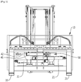
- An example in which the pair of forks is provided will be described with reference to the attached FIGS. 1 to 3 .
- FIGS. 1 to 3 are views for explaining a configuration in which a pair of forks is mounted on a forklift according to a comparative example.
- a carriage frame 10 has first and second cylinders 21 and 31 and a single shift cylinder 41.
- the carriage frame 10 has a side shift frame 50, and the single shift cylinder 41 may be installed on the side shift frame 50.
- a rod 42 of the single shift cylinder 41 is connected to the carriage frame 10.
- a first fork 23 may be moved by the first cylinder 21, and a second fork 33 may be moved by the second cylinder 31.
- carriage frame 10 may be moved in a left or right direction relative to the side shift frame 50 by the single shift cylinder 41.
- the pair of forks is positioned at a position at which a center of gravity of an article is positioned when carrying the article by using the forklift.
- the forklift may repeatedly travel forward and backward to set the positions of the forks with respect to the article.
- the positions of the forks may be sometimes adjusted to the accurate positions only by moving the forks by several centimeters, for example.
- the forklift may lift up the article by adjusting the positions of the forks without traveling.
- the forklift according to the comparative example may move the two forks in a desired direction by operating the single shift cylinder 41.
- the forklift according to the comparative example needs to necessarily operate the single shift cylinder 41 and necessarily have the side shift frame 50 in order to simultaneously move the two forks.
- the forklift according to the comparative example has the side shift frame 50, an operator's visual field is obstructed by the side shift frame 50, which causes a disadvantage in terms of ensuring the visual field.
- a technical object of the present disclosure is to provide a fork movement control device which excludes the single shift cylinder and the side shift frame provided in the comparative example but may simultaneously move two forks by manipulating a single lever, thereby contributing to a reduction in costs incurred to manufacture a forklift by excluding the single shift cylinder and the side shift frame.
- Another object of the present disclosure is to provide a fork movement control device which excludes the side shift frame, thereby contributing to ensuring an operator's visual field.
- a fork movement control device includes: a first control valve unit 110 which is connected to a first head port 25 of a first cylinder 21 through a first flow path line L1 and connected to a first tail port 26 of the first cylinder 21 through a second flow path line L2; a second control valve unit 120 which is connected to a second head port 35 of a second cylinder 31 through a third flow path line L3 and connected to a second tail port 36 of the second cylinder 31 through a fourth flow path line L4; a third control valve unit 130 which is connected to the first flow path line L1 through a fifth flow path line L5 and connected to the third flow path line L3 through a sixth flow path line L6; and a seventh flow path line L7 which connects the second flow path line L2 and the fourth flow path line L4 so that the first tail port 26 and the second tail port 36 are connected.
- first, second, and third control valve units 110, 120, and 130 of the fork movement control device may include: first, second, and third neutral positions 113a, 123a, and 133a at which a flow of a working fluid is stopped; first, second, and third forward direction positions 113b, 123b, and 133b at which the flow of the working fluid is controlled so that the working fluid flows in a forward direction; and first, second, and third reverse direction positions 113c, 123c, and 133c at which the flow of the working fluid is controlled so that the working fluid flows in a reverse direction, respectively.
- the first neutral position 113a of the first control valve unit 110 may be selected or the second neutral position 123a of the second control valve unit 120 may be selected.
- the fork movement control device may control and simultaneously move the two forks by manipulating the single lever even though the single shift cylinder and the side shift frame in the related art are excluded.
- the fork movement control device excludes the side shift frame in the related art, thereby reducing the number of obstacles that obstruct the operator's visual field and enabling the operator to have a wider visual field.
- first and second may be used to describe various constituent elements, but the constituent elements should not be limited by the terms. These terms are used only to distinguish one constituent element from another constituent element.
- a first component may be named a second component, and similarly, the second component may also be named the first component, without departing from the scope of the present disclosure.
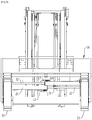
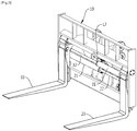
- FIGS. 4 and 5 are views for explaining the configuration in which the pair of forks is mounted on the forklift according to the exemplary embodiment of the present disclosure.
- the forklift according to the exemplary embodiment of the present disclosure has a pair of forks 23 and 33 provided on a carriage frame 10.
- first and second cylinders 21 and 31 may be provided on the carriage frame 10.
- the first fork 23 is connected to a first rod 22 of the first cylinder 21.
- the first fork 23 is moved outward when the first cylinder 21 is extended, and the first fork 23 is moved inward when the first cylinder 21 is retracted.
- the second fork 33 is connected to a second rod 22 of the second cylinder 31.
- the second fork 33 is moved outward when the second cylinder 31 is extended, and the second fork 33 is moved inward when the second cylinder 31 is retracted.
- a direction in which the first cylinder 21 is disposed and a direction in which the second cylinder 31 is disposed are opposite to each other. That is, a width between the two forks is increased when the first cylinder 21 and the second cylinder 31 are simultaneously extended. On the contrary, the width between the two forks is decreased when the first cylinder 21 and the second cylinder 31 are simultaneously retracted.
- FIG. 6 is a view illustrating an example of a main control valve applied to the fork movement control device according to the exemplary embodiment of the present disclosure.
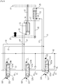
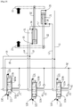
- FIG. 7 is a view for explaining the fork movement control device according to the exemplary embodiment of the present disclosure.
- the main control valve may be configured by a combination of multiple control valves.
- FIG. 6 only the control valve, among the multiple control valves, and only the hydraulic lines, which are involved in operating the forks, are denoted by reference numerals.
- the fork movement control device includes a first control valve unit 110, a second control valve unit 120, and a third control valve unit 130.
- the first control valve unit 110 is connected to a first head port 25 of the first cylinder 21 through a first flow path line L1 and connected to a first tail port 26 of the first cylinder 21 and a second tail port 36 of the second cylinder 31 through a second flow path line L2.
- the first control valve unit 110 may include a first neutral position 113a at which a flow of a working fluid is stopped, a first forward direction position 113b at which the flow of the working fluid is controlled so that the working fluid flows in a forward direction, and a first reverse direction position 113c at which the flow of the working fluid is controlled so that the working fluid flows in a reverse direction.
- the first control valve unit 110 includes an eleventh pressure receiving part 111 which allows the first forward direction position 113b to be selected, and a twelfth pressure receiving part 112 which allows the first reverse direction position 113c to be selected.
- the first neutral position 113a is selected when no pilot pressure is applied to the eleventh and twelfth pressure receiving parts 111 and 112.
- the second control valve unit 120 is connected to a second head port 35 of the second cylinder 31 through a third flow path line L3 and connected to a second tail port 36 of the second cylinder 31 through a fourth flow path line L4.
- the second control valve unit 120 may include a second neutral position 123a at which the flow of the working fluid is stopped, a second forward direction position 123b at which the flow of the working fluid is controlled so that the working fluid flows in the forward direction, and a second reverse direction position 123c at which the flow of the working fluid is controlled so that the working fluid flows in the reverse direction.
- the second control valve unit 120 includes a twenty-first pressure receiving part 121 which allows the second forward direction position 123b to be selected, and a twenty-second pressure receiving part 122 which allows the second reverse direction position 123c to be selected.
- the second neutral position 123a is selected when no pilot pressure is applied to the twenty-first and twenty-second pressure receiving parts 121 and 122.
- the third control valve unit 130 is connected to the first head port 25 of the first cylinder 21 through a fifth flow path line L5 and connected to the second head port 35 of the second cylinder 31 through a sixth flow path line L6.
- the third control valve unit 130 may include a third neutral position 133a at which the flow of the working fluid is stopped, a third forward direction position 133b at which the flow of the working fluid is controlled so that the working fluid flows in the forward direction, and a third reverse direction position 133c at which the flow of the working fluid is controlled so that the working fluid flows in the reverse direction.
- the third control valve unit 130 includes a thirty-first pressure receiving part 131 which allows the third forward direction position 133b to be selected, and a thirty-second pressure receiving part 132 which allows the third reverse direction position 133c to be selected.
- the third neutral position 133a is selected when no pilot pressure is applied to the thirty-first and thirty-second pressure receiving parts 131 and 132.
- first tail port 26 of the first cylinder 21 and the second tail port 36 of the second cylinder 31 are connected to each other through a seventh hydraulic line L7.
- the fork movement control device includes a center bypass line 91 which allows the high-pressure working fluid to pass therethrough when the first, second, and third control valve units 110, 120, and 130 are at the neutral positions, and a parallel line 92 which allows the high-pressure working fluid to be provided to another of the first, second, and third control valve units 110, 120, and 130 while one of the first, second, and third control valve units 110, 120, and 130 operates.
- the fork movement control device according to the exemplary embodiment of the present disclosure has drain lines 93 which allow the working fluid discharged from the first, second, and third control valve units 110, 120, and 130 to flow into a tank.
- first tail port 26 of the first cylinder 21 and the second tail port 36 of the second cylinder 31 are connected to each other, but the second and third control valve units 120 and 130 remain at the neutral positions 123a and 133a, and as a result, the working fluid cannot be discharged via the second and third control valve units 120 and 130. That is, the working fluid cannot be discharged from the second cylinder 31, and as a result, the second cylinder 31 does not operate.
- first tail port 26 of the first cylinder 21 and the second tail port 36 of the second cylinder 31 are connected to each other, but the second and third control valve units 120 and 130 remain at the neutral positions 123a and 133a, and as a result, the working fluid cannot be discharged via the second and third control valve units 120 and 130. That is, the working fluid cannot be discharged from the second cylinder 31, and as a result, the second cylinder 31 does not operate.
- first tail port 26 of the first cylinder 21 and the second tail port 36 of the second cylinder 31 are connected to each other, but the first and third control valve units 110 and 130 remain at the neutral positions 113a and 133a, and as a result, the working fluid cannot be discharged via the first and third control valve units 110 and 130. That is, the working fluid cannot be discharged from the first cylinder 21, and as a result, the first cylinder 21 does not operate.
- the working fluid is provided to the second tail port 36, such that the second cylinder 31 is retracted, and the second fork 33 is moved inward.
- the working fluid discharged from the second head port 35 is discharged through the third flow path line L3.
- first tail port 26 of the first cylinder 21 and the second tail port 36 of the second cylinder 31 are connected to each other, but the first and third control valve units 110 and 130 remain at the neutral positions 113a and 133a, and as a result, the working fluid cannot be discharged via the first and third control valve units 110 and 130. That is, the working fluid cannot be discharged from the first cylinder 21, and as a result, the first cylinder 21 does not operate.
- the working fluid is provided to the first head port 25 via the fifth flow path line L5 and the first flow path line L1, such that the first cylinder 21 is extended, and the first fork 23 is moved outward.
- the working fluid which is discharged through the first tail port 26 of the first cylinder 21, cannot be discharged via the first control valve unit 110.
- the first neutral position 113a of the first control valve unit 110 may be selected.
- the working fluid, which is discharged from the first tail port 26, is provided to the second tail port 36 of the second cylinder 31 through the seventh flow path line L7, such that the second cylinder 31 is retracted, and the second fork 33 is moved inward.
- the working fluid which is discharged through the second head port 35 of the second cylinder 31, is discharged to the drain line 93 via the sixth flow path line L6 through the third control valve unit 130.
- the first and second forks 23 and 33 may be simultaneously moved to the left, as illustrated in FIG. 12 .
- the pilot pressure is applied to the thirty-first pressure receiving part 131 of the third control vavle unit 130, such that the third forward direction position 133b of the third control valve unit 130 may be selected.
- the pilot pressure is applied to the thirty-second pressure receiving part 132 of the third control valve unit 130, the working fluid is provided to the second tail port 35 via the sixth flow path line L6 and the third flow path line L3, such that the second cylinder 31 is extended, and the second fork 33 is moved outward.
- the pilot pressure is applied to the thirty-second pressure receiving part 132, such that the third reverse direction position 133c of the third control valve unit 130 may be selected.
- the working fluid which is discharged through the second tail port 36 of the second cylinder 31, cannot be discharged via the second control valve unit 120.
- the second neutral position 123a of the second control valve unit 120 may be selected.
- the working fluid, which is discharged from the second tail port 36 is provided to the first tail port 26 of the first cylinder 21 through the seventh flow path line L7, such that the first cylinder 21 is retracted, and the first fork 23 is moved inward.
- the working fluid which is discharged through the first head port 25 of the first cylinder 21, is discharged to the drain line 93 via the first flow path line L1 and the fifth hydraulic line L5 through the third control valve unit 130.
- the first and second forks 23 and 33 may be simultaneously moved to the right, as illustrated in FIG. 12 .
- the fork movement control device may simultaneously operate the first and second forks 23 and 33 by controlling the third control valve unit 130 even though the single shift cylinder 41 according to the comparative example is not provided.
- the fork movement control device according to the exemplary embodiment of the present disclosure, it is possible to ensure a wider visual field of the operator in comparison with the comparative example because the side shift frame 50 according to the comparative example is excluded.
- the fork movement control device according to the exemplary embodiment of the present disclosure is applied to the forklift, it is possible to reduce costs incurred to manufacture the forklift because the single shift cylinder 41 and the side shift frame 50 according to the comparative example are excluded.
- the fork movement control device according to the exemplary embodiment of the present disclosure is applied to the forklift, it is possible to simplify the hydraulic lines because the single shift cylinder 41 and the side shift frame 50 are excluded, and it is possible to improve maintainability because associated accessories are excluded.
- the fork movement control device may be used to control and simultaneously move the pair of forks.
Landscapes
- Engineering & Computer Science (AREA)
- Structural Engineering (AREA)
- Mechanical Engineering (AREA)
- Transportation (AREA)
- Life Sciences & Earth Sciences (AREA)
- Geology (AREA)
- Civil Engineering (AREA)
- Chemical & Material Sciences (AREA)
- Combustion & Propulsion (AREA)
- Physics & Mathematics (AREA)
- Fluid Mechanics (AREA)
- General Engineering & Computer Science (AREA)
- Forklifts And Lifting Vehicles (AREA)
Abstract
Description
- The present disclosure relates to a fork movement control device capable of controlling a pair of forks provided on a forklift so that the pair of forks simultaneously moves in any one of the left and right directions.
- In general, a forklift may have a pair of forks at a front side thereof. An example in which the pair of forks is provided will be described with reference to the attached
FIGS. 1 to 3 . - The attached
FIGS. 1 to 3 are views for explaining a configuration in which a pair of forks is mounted on a forklift according to a comparative example. - A
carriage frame 10 has first andsecond cylinders single shift cylinder 41. - In addition, the
carriage frame 10 has aside shift frame 50, and thesingle shift cylinder 41 may be installed on theside shift frame 50. Arod 42 of thesingle shift cylinder 41 is connected to thecarriage frame 10. - A
first fork 23 may be moved by thefirst cylinder 21, and asecond fork 33 may be moved by thesecond cylinder 31. - Further, the
carriage frame 10 may be moved in a left or right direction relative to theside shift frame 50 by thesingle shift cylinder 41. - Ideally, the pair of forks is positioned at a position at which a center of gravity of an article is positioned when carrying the article by using the forklift.
- That is, the forklift may repeatedly travel forward and backward to set the positions of the forks with respect to the article. However, when the positions of the forks slightly deviate from the accurate positions, the positions of the forks may be sometimes adjusted to the accurate positions only by moving the forks by several centimeters, for example. In this case, the forklift may lift up the article by adjusting the positions of the forks without traveling.
- The forklift according to the comparative example may move the two forks in a desired direction by operating the
single shift cylinder 41. - As described above, the forklift according to the comparative example needs to necessarily operate the
single shift cylinder 41 and necessarily have theside shift frame 50 in order to simultaneously move the two forks. - On the other hand, since the forklift according to the comparative example has the
side shift frame 50, an operator's visual field is obstructed by theside shift frame 50, which causes a disadvantage in terms of ensuring the visual field. - Accordingly, a technical object of the present disclosure is to provide a fork movement control device which excludes the single shift cylinder and the side shift frame provided in the comparative example but may simultaneously move two forks by manipulating a single lever, thereby contributing to a reduction in costs incurred to manufacture a forklift by excluding the single shift cylinder and the side shift frame.
- In addition, another object of the present disclosure is to provide a fork movement control device which excludes the side shift frame, thereby contributing to ensuring an operator's visual field.
- To achieve the technical objects, a fork movement control device according to an exemplary embodiment of the present disclosure includes: a first
control valve unit 110 which is connected to afirst head port 25 of afirst cylinder 21 through a first flow path line L1 and connected to afirst tail port 26 of thefirst cylinder 21 through a second flow path line L2; a secondcontrol valve unit 120 which is connected to asecond head port 35 of asecond cylinder 31 through a third flow path line L3 and connected to asecond tail port 36 of thesecond cylinder 31 through a fourth flow path line L4; a thirdcontrol valve unit 130 which is connected to the first flow path line L1 through a fifth flow path line L5 and connected to the third flow path line L3 through a sixth flow path line L6; and a seventh flow path line L7 which connects the second flow path line L2 and the fourth flow path line L4 so that thefirst tail port 26 and thesecond tail port 36 are connected. - In addition, the first, second, and third
control valve units neutral positions forward direction positions reverse direction positions - In addition, when the third
forward direction position 133b or the thirdreverse direction position 133c of the thirdcontrol valve unit 130 is selected, the firstneutral position 113a of the firstcontrol valve unit 110 may be selected or the secondneutral position 123a of the secondcontrol valve unit 120 may be selected. - Other detailed matters of the exemplary embodiment are included in the detailed description and the drawings.
- The fork movement control device according to the exemplary embodiment of the present disclosure, which is configured as described above, may control and simultaneously move the two forks by manipulating the single lever even though the single shift cylinder and the side shift frame in the related art are excluded.
- In addition, the fork movement control device according to the exemplary embodiment of the present disclosure excludes the side shift frame in the related art, thereby reducing the number of obstacles that obstruct the operator's visual field and enabling the operator to have a wider visual field.
-
-
FIGS. 1 to 3 are views for explaining a configuration in which a pair of forks is mounted on a forklift according to a comparative example. -
FIGS. 4 and5 are views for explaining a configuration in which a pair of forks is mounted on a forklift according to an exemplary embodiment of the present disclosure. -
FIG. 6 is a view illustrating an example of a main control valve applied to a fork movement control device according to the exemplary embodiment of the present disclosure. -
FIG. 7 is a view for explaining the fork movement control device according to the exemplary embodiment of the present disclosure. -
FIGS. 8 and9 are views for explaining an example in which the fork movement control device according to the exemplary embodiment of the present disclosure operates only a left fork. -
FIGS. 10 and11 are views for explaining an example in which the fork movement control device according to the exemplary embodiment of the present disclosure operates only a right fork. -
FIGS. 12 and13 are views for explaining an example in which the fork movement control device according to the exemplary embodiment of the present disclosure simultaneously operates both of the left fork and the right fork. -
- 10: Carriage frame
- 21, 31: First and second cylinders
- 22, 32: First and second rods
- 23, 33: First and second forks
- 25, 35: First and second head ports
- 26, 36: First and second tail ports
- 41: Single shift cylinder
- 42: Rod
- 50: Side shift frame
- 91: Center bypass line
- 92: Parallel line
- 93: Drain line
- 110, 120, 130: First, second, and third control valve units
- 111, 112, 121, 122, 131, 132: Eleventh, twelfth, twenty-first, twenty-second, thirty-first, and thirty-second pressure receiving parts
- 113a, 123a, 133a: First, second, and third neutral positions
- 113b, 123b, 133b: First, second, and third forward direction positions
- 113c, 123c, 133c: First, second, and third reverse direction positions
- L1 to L7: First to seventh flow path lines
- Advantages and features of the present disclosure and methods of achieving the advantages and features will be clear with reference to exemplary embodiments described in detail below together with the accompanying drawings.
- Hereinafter, exemplary embodiments of the present disclosure will be described in detail with reference to the accompanying drawings. The exemplary embodiments to be described below are illustrative for helping understand the present disclosure, and it should be understood that the present disclosure may be carried out by being modified in various ways different from the exemplary embodiments described herein. However, in the description of the present disclosure, the specific descriptions and illustrations of publicly known functions or constituent elements will be omitted when it is determined that the specific descriptions may unnecessarily obscure the subject matter of the present disclosure. In addition, to help understand the present disclosure, the accompanying drawings are not illustrated based on actual scales, but some constituent elements may be exaggerated in size.
- Meanwhile, the terms such as "first" and "second" may be used to describe various constituent elements, but the constituent elements should not be limited by the terms. These terms are used only to distinguish one constituent element from another constituent element. For example, a first component may be named a second component, and similarly, the second component may also be named the first component, without departing from the scope of the present disclosure.
- Meanwhile, the terms used in the description are defined considering the functions of the present disclosure and may vary depending on the intention or usual practice of a manufacturer. Therefore, the definitions should be made based on the entire contents of the present specification.
- Like reference numerals indicate like constituent elements throughout the specification.
- First, the configuration in which a pair of forks is mounted on a forklift according to an exemplary embodiment of the present disclosure will be described with reference to
FIGS. 4 and5 .FIGS. 4 and5 are views for explaining the configuration in which the pair of forks is mounted on the forklift according to the exemplary embodiment of the present disclosure. - The forklift according to the exemplary embodiment of the present disclosure has a pair of
forks carriage frame 10. In addition, first andsecond cylinders carriage frame 10. - The
first fork 23 is connected to afirst rod 22 of thefirst cylinder 21. Thefirst fork 23 is moved outward when thefirst cylinder 21 is extended, and thefirst fork 23 is moved inward when thefirst cylinder 21 is retracted. - Likewise, the
second fork 33 is connected to asecond rod 22 of thesecond cylinder 31. Thesecond fork 33 is moved outward when thesecond cylinder 31 is extended, and thesecond fork 33 is moved inward when thesecond cylinder 31 is retracted. - Meanwhile, a direction in which the
first cylinder 21 is disposed and a direction in which thesecond cylinder 31 is disposed are opposite to each other. That is, a width between the two forks is increased when thefirst cylinder 21 and thesecond cylinder 31 are simultaneously extended. On the contrary, the width between the two forks is decreased when thefirst cylinder 21 and thesecond cylinder 31 are simultaneously retracted. - Hereinafter, a fork movement control device according to the exemplary embodiment of the present disclosure will be described with reference to
FIGS. 6 and7 .FIG. 6 is a view illustrating an example of a main control valve applied to the fork movement control device according to the exemplary embodiment of the present disclosure.FIG. 7 is a view for explaining the fork movement control device according to the exemplary embodiment of the present disclosure. - The main control valve may be configured by a combination of multiple control valves. In
FIG. 6 , only the control valve, among the multiple control valves, and only the hydraulic lines, which are involved in operating the forks, are denoted by reference numerals. - The fork movement control device according to the exemplary embodiment of the present disclosure includes a first
control valve unit 110, a secondcontrol valve unit 120, and a thirdcontrol valve unit 130. - The first
control valve unit 110 is connected to afirst head port 25 of thefirst cylinder 21 through a first flow path line L1 and connected to afirst tail port 26 of thefirst cylinder 21 and asecond tail port 36 of thesecond cylinder 31 through a second flow path line L2. - The first
control valve unit 110 may include a firstneutral position 113a at which a flow of a working fluid is stopped, a firstforward direction position 113b at which the flow of the working fluid is controlled so that the working fluid flows in a forward direction, and a firstreverse direction position 113c at which the flow of the working fluid is controlled so that the working fluid flows in a reverse direction. - In addition, the first
control valve unit 110 includes an eleventhpressure receiving part 111 which allows the firstforward direction position 113b to be selected, and a twelfthpressure receiving part 112 which allows the firstreverse direction position 113c to be selected. In the firstcontrol valve unit 110, the firstneutral position 113a is selected when no pilot pressure is applied to the eleventh and twelfthpressure receiving parts - The second
control valve unit 120 is connected to asecond head port 35 of thesecond cylinder 31 through a third flow path line L3 and connected to asecond tail port 36 of thesecond cylinder 31 through a fourth flow path line L4. - The second
control valve unit 120 may include a secondneutral position 123a at which the flow of the working fluid is stopped, a secondforward direction position 123b at which the flow of the working fluid is controlled so that the working fluid flows in the forward direction, and a secondreverse direction position 123c at which the flow of the working fluid is controlled so that the working fluid flows in the reverse direction. - In addition, the second
control valve unit 120 includes a twenty-firstpressure receiving part 121 which allows the secondforward direction position 123b to be selected, and a twenty-secondpressure receiving part 122 which allows the secondreverse direction position 123c to be selected. In the secondcontrol valve unit 120, the secondneutral position 123a is selected when no pilot pressure is applied to the twenty-first and twenty-secondpressure receiving parts - The third
control valve unit 130 is connected to thefirst head port 25 of thefirst cylinder 21 through a fifth flow path line L5 and connected to thesecond head port 35 of thesecond cylinder 31 through a sixth flow path line L6. The thirdcontrol valve unit 130 may include a thirdneutral position 133a at which the flow of the working fluid is stopped, a thirdforward direction position 133b at which the flow of the working fluid is controlled so that the working fluid flows in the forward direction, and a thirdreverse direction position 133c at which the flow of the working fluid is controlled so that the working fluid flows in the reverse direction. - In addition, the third
control valve unit 130 includes a thirty-firstpressure receiving part 131 which allows the thirdforward direction position 133b to be selected, and a thirty-secondpressure receiving part 132 which allows the thirdreverse direction position 133c to be selected. In the thirdcontrol valve unit 130, the thirdneutral position 133a is selected when no pilot pressure is applied to the thirty-first and thirty-secondpressure receiving parts - Meanwhile, the
first tail port 26 of thefirst cylinder 21 and thesecond tail port 36 of thesecond cylinder 31 are connected to each other through a seventh hydraulic line L7. - Meanwhile, the fork movement control device according to the exemplary embodiment of the present disclosure includes a
center bypass line 91 which allows the high-pressure working fluid to pass therethrough when the first, second, and thirdcontrol valve units parallel line 92 which allows the high-pressure working fluid to be provided to another of the first, second, and thirdcontrol valve units control valve units drain lines 93 which allow the working fluid discharged from the first, second, and thirdcontrol valve units - Hereinafter, an operation of the fork movement control device according to the exemplary embodiment of the present disclosure, which is configured as described above, will be described with reference to the attached
FIGS. 8 to 13 . - As illustrated in
FIG. 8 , when the pilot pressure is applied to the eleventhpressure receiving part 111 of the firstcontrol valve unit 110, the working fluid is provided to thefirst head port 25, such that thefirst cylinder 21 is extended, and thefirst fork 23 is moved outward. The working fluid discharged from thefirst tail port 26 is discharged through the second flow path line L2. - Further, the
first tail port 26 of thefirst cylinder 21 and thesecond tail port 36 of thesecond cylinder 31 are connected to each other, but the second and thirdcontrol valve units neutral positions control valve units second cylinder 31, and as a result, thesecond cylinder 31 does not operate. - As illustrated in
FIG. 9 , when the pilot pressure is applied to the twelfthpressure receiving part 112 of the firstcontrol valve unit 110, the working fluid is provided to thefirst tail port 26, such that thefirst cylinder 21 is retracted, and thefirst fork 23 is moved inward. The working fluid discharged from thefirst head port 25 is discharged through the first flow path line L1. - Further, the
first tail port 26 of thefirst cylinder 21 and thesecond tail port 36 of thesecond cylinder 31 are connected to each other, but the second and thirdcontrol valve units neutral positions control valve units second cylinder 31, and as a result, thesecond cylinder 31 does not operate. - Therefore, when a lever for controlling the first
control valve unit 110 is manipulated, only thefirst cylinder 21 operates, and thesecond cylinder 31 does not operate. - As illustrated in
FIG. 10 , when the pilot pressure is applied to the twenty-firstpressure receiving part 121 of the secondcontrol valve unit 120, the working fluid is provided to thesecond head port 35, such that thesecond cylinder 31 is extended, and thesecond fork 33 is moved outward. The working fluid discharged from thesecond tail port 36 is discharged through the fourth flow path line L4. - Further, the
first tail port 26 of thefirst cylinder 21 and thesecond tail port 36 of thesecond cylinder 31 are connected to each other, but the first and thirdcontrol valve units neutral positions control valve units first cylinder 21, and as a result, thefirst cylinder 21 does not operate. - As illustrated in
FIG. 11 , when the pilot pressure is applied to the twenty-secondpressure receiving part 122 of the secondcontrol valve unit 120, the working fluid is provided to thesecond tail port 36, such that thesecond cylinder 31 is retracted, and thesecond fork 33 is moved inward. The working fluid discharged from thesecond head port 35 is discharged through the third flow path line L3. - Further, the
first tail port 26 of thefirst cylinder 21 and thesecond tail port 36 of thesecond cylinder 31 are connected to each other, but the first and thirdcontrol valve units neutral positions control valve units first cylinder 21, and as a result, thefirst cylinder 21 does not operate. - Therefore, when a lever for controlling the second
control valve unit 120 is manipulated, only thesecond cylinder 31 operates, and thefirst cylinder 21 does not operate. - As illustrated in
FIG. 12 , when the pilot pressure is applied to the thirty-firstpressure receiving part 131 of the thirdcontrol valve unit 130, the working fluid is provided to thefirst head port 25 via the fifth flow path line L5 and the first flow path line L1, such that thefirst cylinder 21 is extended, and thefirst fork 23 is moved outward. - Meanwhile, because the first
control valve unit 110 remains at the neutral position, the working fluid, which is discharged through thefirst tail port 26 of thefirst cylinder 21, cannot be discharged via the firstcontrol valve unit 110. Specifically, the firstneutral position 113a of the firstcontrol valve unit 110 may be selected. Further, the working fluid, which is discharged from thefirst tail port 26, is provided to thesecond tail port 36 of thesecond cylinder 31 through the seventh flow path line L7, such that thesecond cylinder 31 is retracted, and thesecond fork 33 is moved inward. - The working fluid, which is discharged through the
second head port 35 of thesecond cylinder 31, is discharged to thedrain line 93 via the sixth flow path line L6 through the thirdcontrol valve unit 130. - That is, when the pilot pressure is applied to the thirty-first
pressure receiving part 131 of the thirdcontrol valve unit 130, the first andsecond forks FIG. 12 . Specifically, the pilot pressure is applied to the thirty-firstpressure receiving part 131 of the thirdcontrol vavle unit 130, such that the thirdforward direction position 133b of the thirdcontrol valve unit 130 may be selected. - As illustrated in
FIG. 13 , when the pilot pressure is applied to the thirty-secondpressure receiving part 132 of the thirdcontrol valve unit 130, the working fluid is provided to thesecond tail port 35 via the sixth flow path line L6 and the third flow path line L3, such that thesecond cylinder 31 is extended, and thesecond fork 33 is moved outward. Specifically, the pilot pressure is applied to the thirty-secondpressure receiving part 132, such that the thirdreverse direction position 133c of the thirdcontrol valve unit 130 may be selected. - Meanwhile, because the second
control valve unit 120 remains at the neutral position, the working fluid, which is discharged through thesecond tail port 36 of thesecond cylinder 31, cannot be discharged via the secondcontrol valve unit 120. Specifically, the secondneutral position 123a of the secondcontrol valve unit 120 may be selected. Further, the working fluid, which is discharged from thesecond tail port 36, is provided to thefirst tail port 26 of thefirst cylinder 21 through the seventh flow path line L7, such that thefirst cylinder 21 is retracted, and thefirst fork 23 is moved inward. - The working fluid, which is discharged through the
first head port 25 of thefirst cylinder 21, is discharged to thedrain line 93 via the first flow path line L1 and the fifth hydraulic line L5 through the thirdcontrol valve unit 130. - That is, when the pilot pressure is applied to the thirty-second
pressure receiving part 132 of the thirdcontrol valve unit 130, the first andsecond forks FIG. 12 . - That is, the fork movement control device according to the exemplary embodiment of the present disclosure may simultaneously operate the first and
second forks control valve unit 130 even though thesingle shift cylinder 41 according to the comparative example is not provided. - In addition, according to the fork movement control device according to the exemplary embodiment of the present disclosure, , it is possible to ensure a wider visual field of the operator in comparison with the comparative example because the
side shift frame 50 according to the comparative example is excluded. - In addition, in the case in which the fork movement control device according to the exemplary embodiment of the present disclosure is applied to the forklift, it is possible to reduce costs incurred to manufacture the forklift because the
single shift cylinder 41 and theside shift frame 50 according to the comparative example are excluded. - In addition, in the case in which the fork movement control device according to the exemplary embodiment of the present disclosure is applied to the forklift, it is possible to simplify the arrangement of the hydraulic lines because the hydraulic lines for operating the
single shift cylinder 41 according to the comparative example may be excluded. - In addition, in the case in which the fork movement control device according to the exemplary embodiment of the present disclosure is applied to the forklift, it is possible to simplify the hydraulic lines because the
single shift cylinder 41 and theside shift frame 50 are excluded, and it is possible to improve maintainability because associated accessories are excluded. - While the exemplary embodiments of the present disclosure have been described with reference to the accompanying drawings, those skilled in the art will understand that the present disclosure may be carried out in any other specific form without changing the technical spirit or an essential feature thereof.
- Accordingly, it should be understood that the aforementioned exemplary embodiments are described for illustration in all aspects and is not limited, and the scope of the present disclosure shall be represented by the claims to be described below, and it should be construed that all of the changes or modified forms induced from the meaning and the scope of the claims, and an equivalent concept thereto are included in the scope of the present disclosure.
- The fork movement control device according to the exemplary embodiment of the present disclosure may be used to control and simultaneously move the pair of forks.
Claims (3)
- A fork movement control device comprising:a first control valve unit which is connected to a first head port of a first cylinder through a first flow path line and connected to a first tail port of the first cylinder through a second flow path line;a second control valve unit which is connected to a second head port of a second cylinder through a third flow path line and connected to a second tail port of the second cylinder through a fourth flow path line;a third control valve unit which is connected to the first flow path line through a fifth flow path line and connected to the third flow path line through a sixth flow path line; anda seventh flow path line which connects the second flow path line and the fourth flow path line so that the first tail port and the second tail port are connected.
- The fork movement control device of claim 1, wherein the first, second, and third control valve units include:first, second, and third neutral positions at which a flow of a working fluid is stopped;first, second, and third forward direction positions at which the flow of the working fluid is controlled so that the working fluid flows in a forward direction; andfirst, second, and third reverse direction positions at which the flow of the working fluid is controlled so that the working fluid flows in a reverse direction, respectively.
- The fork movement control device of claim 2, wherein when the third forward direction position or the third reverse direction position of the third control valve unit is selected, the first neutral position of the first control valve unit is selected or the second neutral position of the second control valve unit is selected.
Applications Claiming Priority (2)
| Application Number | Priority Date | Filing Date | Title |
|---|---|---|---|
| KR1020160098385A KR102044059B1 (en) | 2016-08-02 | 2016-08-02 | Control device for shifting of the fork |
| PCT/KR2017/008326 WO2018026184A1 (en) | 2016-08-02 | 2017-08-02 | Fork movement control device |
Publications (2)
| Publication Number | Publication Date |
|---|---|
| EP3495315A1 true EP3495315A1 (en) | 2019-06-12 |
| EP3495315A4 EP3495315A4 (en) | 2020-03-18 |
Family
ID=61073472
Family Applications (1)
| Application Number | Title | Priority Date | Filing Date |
|---|---|---|---|
| EP17837235.5A Pending EP3495315A4 (en) | 2016-08-02 | 2017-08-02 | DEVICE FOR CONTROLLING THE MOVEMENT OF A FORK |
Country Status (5)
| Country | Link |
|---|---|
| US (1) | US11401144B2 (en) |
| EP (1) | EP3495315A4 (en) |
| KR (1) | KR102044059B1 (en) |
| CN (1) | CN109562923B (en) |
| WO (1) | WO2018026184A1 (en) |
Families Citing this family (2)
| Publication number | Priority date | Publication date | Assignee | Title |
|---|---|---|---|---|
| IT201900000607A1 (en) * | 2019-01-15 | 2020-07-15 | Manitou Italia Srl | Improved Equipment. |
| EP4238927A1 (en) * | 2022-03-04 | 2023-09-06 | J.C. Bamford Excavators Limited | A side-shift fork carriage for a material handling machine |
Family Cites Families (12)
| Publication number | Priority date | Publication date | Assignee | Title |
|---|---|---|---|---|
| US2795346A (en) * | 1953-07-16 | 1957-06-11 | Hyster Co | Load grip side shift for lift trucks |
| US3184088A (en) * | 1961-09-11 | 1965-05-18 | Clark Equipment Co | Hydraulic control system for moving clamping members on a lift truck laterally, independently of each other, and simultaneously in the same and opposite directions |
| US3692198A (en) * | 1970-12-28 | 1972-09-19 | Clark Equipment Co | Hydraulic lift truck with small number of fluid lines |
| US4335992A (en) * | 1980-01-07 | 1982-06-22 | Towmotor Corporation | Side shift fork adjustable carriage |
| US5088880A (en) * | 1990-12-03 | 1992-02-18 | Caterpillar Industrial Inc. | Fluid operated fork positioning control system |
| JP3793705B2 (en) * | 2001-09-28 | 2006-07-05 | 株式会社アイチコーポレーション | Car body lifting support device |
| KR101127797B1 (en) * | 2004-12-20 | 2012-03-27 | 두산산업차량 주식회사 | Device for controlling distance fork in forklift truck |
| KR100605010B1 (en) * | 2004-12-27 | 2006-07-28 | 두산인프라코어 주식회사 | Hydraulic system for attachment adjustment of forklift |
| JP5038702B2 (en) | 2006-12-19 | 2012-10-03 | Tcm株式会社 | Fork shift device |
| KR101529330B1 (en) * | 2009-12-23 | 2015-06-29 | 주식회사 두산 | Fork-operated hydraulic device for forklift |
| JP5352663B2 (en) * | 2011-12-26 | 2013-11-27 | 株式会社豊田自動織機 | Hydraulic control device for forklift |
| US10494241B2 (en) * | 2016-09-16 | 2019-12-03 | Cascade Corporation | Hydraulic clamping systems having load side-shifting variably responsive to load weight |
-
2016
- 2016-08-02 KR KR1020160098385A patent/KR102044059B1/en active Active
-
2017
- 2017-08-02 WO PCT/KR2017/008326 patent/WO2018026184A1/en not_active Ceased
- 2017-08-02 CN CN201780048864.2A patent/CN109562923B/en active Active
- 2017-08-02 EP EP17837235.5A patent/EP3495315A4/en active Pending
- 2017-08-02 US US16/322,532 patent/US11401144B2/en active Active
Also Published As
| Publication number | Publication date |
|---|---|
| CN109562923B (en) | 2021-11-26 |
| US20190202676A1 (en) | 2019-07-04 |
| WO2018026184A1 (en) | 2018-02-08 |
| CN109562923A (en) | 2019-04-02 |
| KR102044059B1 (en) | 2019-11-12 |
| KR20180014939A (en) | 2018-02-12 |
| EP3495315A4 (en) | 2020-03-18 |
| US11401144B2 (en) | 2022-08-02 |
Similar Documents
| Publication | Publication Date | Title |
|---|---|---|
| US10473125B2 (en) | Hydraulic actuator control circuit | |
| CN111033056B (en) | Hydraulic circuit | |
| EP3315386B1 (en) | Steering device for construction/transport/farm machine | |
| EP2774827A1 (en) | Steering device of wheel loader | |
| EP3037676B1 (en) | Multidirectional switching valve for construction machine | |
| US9003951B2 (en) | Hydraulic system with bi-directional regeneration | |
| JP6656913B2 (en) | Working machine hydraulic system | |
| US9551361B2 (en) | Travel control valve | |
| KR20150122695A (en) | Merging circuit of hydraulic apparatus | |
| CN113302403B (en) | Hydraulic control circuits for construction machinery | |
| US11401144B2 (en) | Fork movement control device | |
| JP6282528B2 (en) | Construction machinery | |
| JP6196567B2 (en) | Hydraulic drive system for construction machinery | |
| KR101529330B1 (en) | Fork-operated hydraulic device for forklift | |
| KR102448755B1 (en) | Construction machine control system and construction machine control method using the same | |
| EP3093214A1 (en) | Hydraulic steering system | |
| CN102888875B (en) | Travelling control loop, hydraulic crawler excavator | |
| CN105402177B (en) | A kind of executing agency's adjusting means and engineering machinery | |
| KR101980417B1 (en) | Control device for shifting of the fork | |
| CN106460880B (en) | Fluid pressure control device for construction machine | |
| US12497760B2 (en) | Hydraulic drive apparatus | |
| CN106795899A (en) | Especially as three cylinders of speed-changer executing mechanism | |
| US20160130787A1 (en) | Flow rate control valve for construction machine | |
| WO2014073551A1 (en) | Fluid pressure control device for power shovel | |
| KR102038728B1 (en) | Control device for shifting of the fork |
Legal Events
| Date | Code | Title | Description |
|---|---|---|---|
| STAA | Information on the status of an ep patent application or granted ep patent |
Free format text: STATUS: THE INTERNATIONAL PUBLICATION HAS BEEN MADE |
|
| PUAI | Public reference made under article 153(3) epc to a published international application that has entered the european phase |
Free format text: ORIGINAL CODE: 0009012 |
|
| STAA | Information on the status of an ep patent application or granted ep patent |
Free format text: STATUS: REQUEST FOR EXAMINATION WAS MADE |
|
| 17P | Request for examination filed |
Effective date: 20190228 |
|
| AK | Designated contracting states |
Kind code of ref document: A1 Designated state(s): AL AT BE BG CH CY CZ DE DK EE ES FI FR GB GR HR HU IE IS IT LI LT LU LV MC MK MT NL NO PL PT RO RS SE SI SK SM TR |
|
| AX | Request for extension of the european patent |
Extension state: BA ME |
|
| DAV | Request for validation of the european patent (deleted) | ||
| DAX | Request for extension of the european patent (deleted) | ||
| A4 | Supplementary search report drawn up and despatched |
Effective date: 20200214 |
|
| RIC1 | Information provided on ipc code assigned before grant |
Ipc: F15B 13/02 20060101ALI20200210BHEP Ipc: B66F 17/00 20060101ALI20200210BHEP Ipc: B66F 9/14 20060101ALI20200210BHEP Ipc: B66F 9/22 20060101AFI20200210BHEP |
|
| RAP1 | Party data changed (applicant data changed or rights of an application transferred) |
Owner name: DOOSAN INDUSTRIAL VEHICLE CO., LTD. |
|
| RAP1 | Party data changed (applicant data changed or rights of an application transferred) |
Owner name: DOOSAN INDUSTRIAL VEHICLE CO., LTD. |
|
| STAA | Information on the status of an ep patent application or granted ep patent |
Free format text: STATUS: EXAMINATION IS IN PROGRESS |
|
| 17Q | First examination report despatched |
Effective date: 20231002 |
|
| RAP3 | Party data changed (applicant data changed or rights of an application transferred) |
Owner name: DOOSAN BOBCAT KOREA CO., LTD. |