EP3495212A1 - Interior member for vehicle - Google Patents
Interior member for vehicle Download PDFInfo
- Publication number
- EP3495212A1 EP3495212A1 EP18210540.3A EP18210540A EP3495212A1 EP 3495212 A1 EP3495212 A1 EP 3495212A1 EP 18210540 A EP18210540 A EP 18210540A EP 3495212 A1 EP3495212 A1 EP 3495212A1
- Authority
- EP
- European Patent Office
- Prior art keywords
- base material
- vehicle
- design surface
- conductive portion
- interior member
- Prior art date
- Legal status (The legal status is an assumption and is not a legal conclusion. Google has not performed a legal analysis and makes no representation as to the accuracy of the status listed.)
- Granted
Links
Images



Classifications
-
- B—PERFORMING OPERATIONS; TRANSPORTING
- B60—VEHICLES IN GENERAL
- B60R—VEHICLES, VEHICLE FITTINGS, OR VEHICLE PARTS, NOT OTHERWISE PROVIDED FOR
- B60R13/00—Elements for body-finishing, identifying, or decorating; Arrangements or adaptations for advertising purposes
- B60R13/02—Internal Trim mouldings ; Internal Ledges; Wall liners for passenger compartments; Roof liners
- B60R13/0256—Dashboard liners
-
- B—PERFORMING OPERATIONS; TRANSPORTING
- B60—VEHICLES IN GENERAL
- B60R—VEHICLES, VEHICLE FITTINGS, OR VEHICLE PARTS, NOT OTHERWISE PROVIDED FOR
- B60R13/00—Elements for body-finishing, identifying, or decorating; Arrangements or adaptations for advertising purposes
- B60R13/02—Internal Trim mouldings ; Internal Ledges; Wall liners for passenger compartments; Roof liners
-
- B—PERFORMING OPERATIONS; TRANSPORTING
- B32—LAYERED PRODUCTS
- B32B—LAYERED PRODUCTS, i.e. PRODUCTS BUILT-UP OF STRATA OF FLAT OR NON-FLAT, e.g. CELLULAR OR HONEYCOMB, FORM
- B32B27/00—Layered products comprising a layer of synthetic resin
- B32B27/06—Layered products comprising a layer of synthetic resin as the main or only constituent of a layer, which is next to another layer of the same or of a different material
- B32B27/065—Layered products comprising a layer of synthetic resin as the main or only constituent of a layer, which is next to another layer of the same or of a different material of foam
-
- B—PERFORMING OPERATIONS; TRANSPORTING
- B32—LAYERED PRODUCTS
- B32B—LAYERED PRODUCTS, i.e. PRODUCTS BUILT-UP OF STRATA OF FLAT OR NON-FLAT, e.g. CELLULAR OR HONEYCOMB, FORM
- B32B27/00—Layered products comprising a layer of synthetic resin
- B32B27/28—Layered products comprising a layer of synthetic resin comprising synthetic resins not wholly covered by any one of the sub-groups B32B27/30 - B32B27/42
- B32B27/281—Layered products comprising a layer of synthetic resin comprising synthetic resins not wholly covered by any one of the sub-groups B32B27/30 - B32B27/42 comprising polyimides
-
- B—PERFORMING OPERATIONS; TRANSPORTING
- B32—LAYERED PRODUCTS
- B32B—LAYERED PRODUCTS, i.e. PRODUCTS BUILT-UP OF STRATA OF FLAT OR NON-FLAT, e.g. CELLULAR OR HONEYCOMB, FORM
- B32B5/00—Layered products characterised by the non- homogeneity or physical structure, i.e. comprising a fibrous, filamentary, particulate or foam layer; Layered products characterised by having a layer differing constitutionally or physically in different parts
- B32B5/02—Layered products characterised by the non- homogeneity or physical structure, i.e. comprising a fibrous, filamentary, particulate or foam layer; Layered products characterised by having a layer differing constitutionally or physically in different parts characterised by structural features of a fibrous or filamentary layer
- B32B5/08—Layered products characterised by the non- homogeneity or physical structure, i.e. comprising a fibrous, filamentary, particulate or foam layer; Layered products characterised by having a layer differing constitutionally or physically in different parts characterised by structural features of a fibrous or filamentary layer the fibres or filaments of a layer being of different substances, e.g. conjugate fibres, mixture of different fibres
-
- B—PERFORMING OPERATIONS; TRANSPORTING
- B32—LAYERED PRODUCTS
- B32B—LAYERED PRODUCTS, i.e. PRODUCTS BUILT-UP OF STRATA OF FLAT OR NON-FLAT, e.g. CELLULAR OR HONEYCOMB, FORM
- B32B9/00—Layered products comprising a layer of a particular substance not covered by groups B32B11/00 - B32B29/00
- B32B9/02—Layered products comprising a layer of a particular substance not covered by groups B32B11/00 - B32B29/00 comprising animal or vegetable substances, e.g. cork, bamboo, starch
- B32B9/025—Layered products comprising a layer of a particular substance not covered by groups B32B11/00 - B32B29/00 comprising animal or vegetable substances, e.g. cork, bamboo, starch comprising leather
-
- B—PERFORMING OPERATIONS; TRANSPORTING
- B32—LAYERED PRODUCTS
- B32B—LAYERED PRODUCTS, i.e. PRODUCTS BUILT-UP OF STRATA OF FLAT OR NON-FLAT, e.g. CELLULAR OR HONEYCOMB, FORM
- B32B9/00—Layered products comprising a layer of a particular substance not covered by groups B32B11/00 - B32B29/00
- B32B9/04—Layered products comprising a layer of a particular substance not covered by groups B32B11/00 - B32B29/00 comprising such particular substance as the main or only constituent of a layer, which is next to another layer of the same or of a different material
- B32B9/046—Layered products comprising a layer of a particular substance not covered by groups B32B11/00 - B32B29/00 comprising such particular substance as the main or only constituent of a layer, which is next to another layer of the same or of a different material of foam
-
- B—PERFORMING OPERATIONS; TRANSPORTING
- B60—VEHICLES IN GENERAL
- B60K—ARRANGEMENT OR MOUNTING OF PROPULSION UNITS OR OF TRANSMISSIONS IN VEHICLES; ARRANGEMENT OR MOUNTING OF PLURAL DIVERSE PRIME-MOVERS IN VEHICLES; AUXILIARY DRIVES FOR VEHICLES; INSTRUMENTATION OR DASHBOARDS FOR VEHICLES; ARRANGEMENTS IN CONNECTION WITH COOLING, AIR INTAKE, GAS EXHAUST OR FUEL SUPPLY OF PROPULSION UNITS IN VEHICLES
- B60K37/00—Dashboards
- B60K37/20—Dashboard panels
-
- B—PERFORMING OPERATIONS; TRANSPORTING
- B60—VEHICLES IN GENERAL
- B60R—VEHICLES, VEHICLE FITTINGS, OR VEHICLE PARTS, NOT OTHERWISE PROVIDED FOR
- B60R16/00—Electric or fluid circuits specially adapted for vehicles and not otherwise provided for; Arrangement of elements of electric or fluid circuits specially adapted for vehicles and not otherwise provided for
- B60R16/02—Electric or fluid circuits specially adapted for vehicles and not otherwise provided for; Arrangement of elements of electric or fluid circuits specially adapted for vehicles and not otherwise provided for electric constitutive elements
-
- B—PERFORMING OPERATIONS; TRANSPORTING
- B60—VEHICLES IN GENERAL
- B60R—VEHICLES, VEHICLE FITTINGS, OR VEHICLE PARTS, NOT OTHERWISE PROVIDED FOR
- B60R16/00—Electric or fluid circuits specially adapted for vehicles and not otherwise provided for; Arrangement of elements of electric or fluid circuits specially adapted for vehicles and not otherwise provided for
- B60R16/02—Electric or fluid circuits specially adapted for vehicles and not otherwise provided for; Arrangement of elements of electric or fluid circuits specially adapted for vehicles and not otherwise provided for electric constitutive elements
- B60R16/03—Electric or fluid circuits specially adapted for vehicles and not otherwise provided for; Arrangement of elements of electric or fluid circuits specially adapted for vehicles and not otherwise provided for electric constitutive elements for supply of electrical power to vehicle subsystems or for
-
- H—ELECTRICITY
- H05—ELECTRIC TECHNIQUES NOT OTHERWISE PROVIDED FOR
- H05K—PRINTED CIRCUITS; CASINGS OR CONSTRUCTIONAL DETAILS OF ELECTRIC APPARATUS; MANUFACTURE OF ASSEMBLAGES OF ELECTRICAL COMPONENTS
- H05K3/00—Apparatus or processes for manufacturing printed circuits
- H05K3/0011—Working of insulating substrates or insulating layers
- H05K3/0014—Shaping of the substrate, e.g. by moulding
-
- H—ELECTRICITY
- H05—ELECTRIC TECHNIQUES NOT OTHERWISE PROVIDED FOR
- H05K—PRINTED CIRCUITS; CASINGS OR CONSTRUCTIONAL DETAILS OF ELECTRIC APPARATUS; MANUFACTURE OF ASSEMBLAGES OF ELECTRICAL COMPONENTS
- H05K3/00—Apparatus or processes for manufacturing printed circuits
- H05K3/10—Apparatus or processes for manufacturing printed circuits in which conductive material is applied to the insulating support in such a manner as to form the desired conductive pattern
- H05K3/101—Apparatus or processes for manufacturing printed circuits in which conductive material is applied to the insulating support in such a manner as to form the desired conductive pattern by casting or moulding of conductive material
-
- B—PERFORMING OPERATIONS; TRANSPORTING
- B32—LAYERED PRODUCTS
- B32B—LAYERED PRODUCTS, i.e. PRODUCTS BUILT-UP OF STRATA OF FLAT OR NON-FLAT, e.g. CELLULAR OR HONEYCOMB, FORM
- B32B2266/00—Composition of foam
- B32B2266/02—Organic
- B32B2266/0214—Materials belonging to B32B27/00
- B32B2266/0278—Polyurethane
-
- B—PERFORMING OPERATIONS; TRANSPORTING
- B32—LAYERED PRODUCTS
- B32B—LAYERED PRODUCTS, i.e. PRODUCTS BUILT-UP OF STRATA OF FLAT OR NON-FLAT, e.g. CELLULAR OR HONEYCOMB, FORM
- B32B2305/00—Condition, form or state of the layers or laminate
- B32B2305/34—Inserts
-
- B—PERFORMING OPERATIONS; TRANSPORTING
- B32—LAYERED PRODUCTS
- B32B—LAYERED PRODUCTS, i.e. PRODUCTS BUILT-UP OF STRATA OF FLAT OR NON-FLAT, e.g. CELLULAR OR HONEYCOMB, FORM
- B32B2605/00—Vehicles
-
- B—PERFORMING OPERATIONS; TRANSPORTING
- B32—LAYERED PRODUCTS
- B32B—LAYERED PRODUCTS, i.e. PRODUCTS BUILT-UP OF STRATA OF FLAT OR NON-FLAT, e.g. CELLULAR OR HONEYCOMB, FORM
- B32B2605/00—Vehicles
- B32B2605/003—Interior finishings
-
- B—PERFORMING OPERATIONS; TRANSPORTING
- B60—VEHICLES IN GENERAL
- B60K—ARRANGEMENT OR MOUNTING OF PROPULSION UNITS OR OF TRANSMISSIONS IN VEHICLES; ARRANGEMENT OR MOUNTING OF PLURAL DIVERSE PRIME-MOVERS IN VEHICLES; AUXILIARY DRIVES FOR VEHICLES; INSTRUMENTATION OR DASHBOARDS FOR VEHICLES; ARRANGEMENTS IN CONNECTION WITH COOLING, AIR INTAKE, GAS EXHAUST OR FUEL SUPPLY OF PROPULSION UNITS IN VEHICLES
- B60K2360/00—Indexing scheme associated with groups B60K35/00 or B60K37/00 relating to details of instruments or dashboards
- B60K2360/40—Hardware adaptations for dashboards or instruments
- B60K2360/46—Electrical connections
-
- B—PERFORMING OPERATIONS; TRANSPORTING
- B60—VEHICLES IN GENERAL
- B60R—VEHICLES, VEHICLE FITTINGS, OR VEHICLE PARTS, NOT OTHERWISE PROVIDED FOR
- B60R13/00—Elements for body-finishing, identifying, or decorating; Arrangements or adaptations for advertising purposes
- B60R13/02—Internal Trim mouldings ; Internal Ledges; Wall liners for passenger compartments; Roof liners
- B60R2013/0287—Internal Trim mouldings ; Internal Ledges; Wall liners for passenger compartments; Roof liners integrating other functions or accessories
Definitions
- the invention relates to an interior member for a vehicle.
- JP 8-216733 A discloses an invention related to an electrical component mounted body.
- a rear surface (surface opposite to design surface) of an insert base material constituting a portion of an instrument panel is provided with a film-shaped wiring body, the film-shaped wiring body being integrated with the insert base material.
- An insulation film is removed from a portion of the film-shaped wiring body that comes into contact with an electrical component such that a conductive portion printed on a front surface of the film-shaped wiring body is exposed.
- a conductive portion of the electrical component and the conductive portion of the wiring body are in contact with each other and thus it is possible to electrically connect the electrical component and the wiring body to each other without routing a wire harness or the like close to a rear surface of the instrument panel.
- the insert base material and the electrical component need to be in direct contact with each other. Therefore, there is room for improvement in a point that there is a limit on the degree of freedom in designing a portion of the electrical component that is opposite to the design surface of the instrument panel and the vicinity thereof.
- the invention provides an interior member for a vehicle with which it is possible to supply power to an electrical component without routing a wire harness or the like and to secure the degree of freedom in designing a portion opposite to a design surface and the vicinity thereof.
- a first aspect of the invention relates to an interior member for a vehicle.
- the interior member includes a base material formed of a resin, a front surface portion, and a conductive portion.
- the front surface portion is configured to constitute a portion of a design surface in a vehicle cabin and cover a surface of the base material that is on the design surface side.
- the conductive portion is integrally provided with the base material in a state where a portion of the conductive portion that is opposite to the design surface is in close contact with the base material and a portion of the conductive portion that is on the design surface side faces the front surface portion such that power is supplied to an electrical component installed in the vehicle through the conductive portion, the conductive portion being formed of a metal.
- the base material formed of a resin and the front surface portion constituting a portion of the design surface in the vehicle cabin are provided and the front surface portion covers the surface of the base material that is on the design surface side.
- the conductive portion formed of a metal is integrally provided with the base material and it is possible to supply power to the electrical component installed in the vehicle through the conductive portion without routing the wire harness or the like in the vicinity of the base material.
- the conductive portion is provided in the base material in a state where a portion of the conductive portion that is opposite to the design surface in the vehicle cabin is in close contact with the base material and a portion of the conductive portion that is on the design surface side faces the front surface portion, and the conductive portion and the base material can be formed through or insert molding or two-color molding. Therefore, even when the base material is provided with the conductive portion, the influence of the conductive portion on the configuration of a portion of the base material that is opposite to the design surface in the vehicle cabin can be further suppressed.
- the base material and the conductive portion may be formed through two-color molding and may constitute an integrated molded product.
- the base material and the conductive portion are formed through two-color molding and constitute an integrated molded product. Therefore, it is possible to simplify an operation of mounting the interior member for a vehicle and to improve the degree of freedom in designing the interior member for a vehicle in comparison with a case where the base material and the conductive are configured separately from each other.
- a second aspect of the invention relates to an interior member for a vehicle.
- the interior member includes a base material formed of a resin, a front surface portion, and a conductive portion.
- the front surface portion constitutes a portion of a design surface in a vehicle cabin and covers a surface of the base material that is on the design surface side.
- the conductive portion is built into the base material such that power is supplied to an electrical component installed in the vehicle through the conductive portion, the conductive portion being formed of a metal.
- the interior member according to the second aspect of the invention has basically the same configuration as the interior member according to the first aspect of the invention, and exhibits the same operation as that of the interior member according to the first aspect of the invention.
- the conductive portion is built into the base material and the influence of the conductive portion on the configuration of a portion of the base material that is close to the design surface in the vehicle cabin and a portion of the base material that is opposite to design surface can be further suppressed.
- the base material may be provided with a rib portion that protrudes from a surface of the base material that is opposite to the design surface.
- the base material is provided with the rib portion and the rib portion protrudes from the surface of the base material that is opposite to the design surface in the vehicle cabin. Therefore, it is possible to reinforce the base material with the rib portion without an influence on the design surface of the interior member for a vehicle.
- a portion of the conductive portion may be exposed at a surface of the base material that is opposite to the design surface.
- a portion of the conductive portion is exposed at the surface of the base material that is opposite to the design surface in the vehicle cabin and the electrical component disposed in the vehicle cabin can be connected to the conductive portion at a portion of the base material that is opposite to the design surface.
- the base material may constitute a portion of an instrument panel and the front surface portion may include a foam layer that is in close contact with the base material while being disposed on a portion of the base material that is on the design surface side and a cover material that constitutes the design surface and is in close contact with the foam layer.
- the base material constitutes a portion of the instrument panel and the foam layer is disposed on a portion of the base material that is close to the design surface in the vehicle cabin in a state of being in close contact with the base material.
- the cover material constituting the design surface in the vehicle cabin is in close contact with the foam layer. Therefore, it is possible to further improve the design and texture of the instrument panel and it is possible to use the conductive portion when supplying power to the electrical component disposed in the vicinity of the instrument panel.
- the interior member according to the first aspect of the invention has an excellent effect that it is possible to supply power to an electrical component without routing a wire harness or the like and to secure the degree of freedom in designing a portion opposite to a design surface and the vicinity thereof.
- the interior member according to the first aspect of the invention further has an excellent effect that it is possible to improve the degree of freedom in designing a design surface in a vehicle cabin while reducing the number of processes for assembling the vehicle cabin.
- the interior member according to the second aspect of the invention has the same effects as those of the interior member according to the first aspect of the invention.
- the interior member according to the first and second aspects of the invention further has an excellent effect that it is possible to secure the design of the design surface of the interior member for a vehicle and to stably support a load that is applied to the design surface from the inside of the vehicle cabin.
- the interior member according to the first and second aspects of the invention further has an excellent effect that it is possible to effectively use a space in the vicinity of the interior member for a vehicle since connection point of the electrical component is set in the vicinity of the interior member for a vehicle.
- the interior member according to the first and second aspects of the invention further has an excellent effect that it is possible to make the instrument panel look luxurious and it is possible to simplify an operation of attaching the electrical component in the vicinity of the instrument panel.
- FIGS. 1 to 4 An arrow FR appropriately shown in the drawings represents a vehicle front side, an arrow UP represents a vehicle upper side, and an arrow OUT represents an outer side in a vehicle width direction.
- an instrument panel 14 as the interior member for a vehicle is disposed on the vehicle front side in a "vehicle cabin 12" of a "vehicle 10".
- the instrument panel 14 is configured to include an instrument panel upper portion 14A that constitutes a vehicle upper side portion of the instrument panel 14 and extends in the vehicle width direction and a vehicle front-rear direction, an instrument panel lower portion 14B that is provided to face a driver's seat (not shown), and an instrument panel lower portion 14C that is provided to face a passenger seat (not shown).
- the instrument panel 14 is configured to include a "base material 16" formed of a resin, a "foam layer 18" configured with foamed resin such as polyurethane, and a "cover material 20" configured with synthetic leather or the like.
- the major portion of the base material 16 is configured with a main body portion 16A formed in a plate-like shape and a "front surface 16A1" of the main body portion 16A is covered with the foam layer 18 and the cover material 20, the front surface 16A1 being positioned close to a design surface 22 in the vehicle cabin 12.
- a rear surface 16A2 of the main body portion 16A is provided with a plurality of "rib portions 16B" that protrudes in a thickness direction of the main body portion 16A from the rear surface 16A2 that is opposite to the front surface 16A1.
- Each rib portion 16B illustrated in FIG. 1 has a plate-like shape extending in the vehicle front-rear direction, for example.
- each rib portion 16B may have a plate-like shape extending in a direction other than the vehicle front-rear direction and may be formed to have a grid shape as seen from the thickness direction of the main body portion 16A.
- the foam layer 18 is provided along the front surface 16A1 of the main body portion 16A of the base material 16 in a state where the thickness thereof is constant and is in close contact with the base material 16. A portion of the foam layer 18 that is on the design surface 22 side is covered by the sheet-shaped cover material 20 constituting a portion of the design surface 22 and is in close contact with the cover material 20.
- a plurality of electrical components is disposed on an upper surface 14A1 (portion of design surface 22) of the instrument panel upper portion 14A that is on the vehicle upper side.
- a "head-up display 26" is disposed on a portion of the upper surface 14A1 of the instrument panel upper portion 14A that is positioned behind the central portion of the upper surface 14A1 in the vehicle front-rear direction.
- a "beacon sensor 28" and an “auto-light sensor 30" are disposed on a portion of the upper surface 14A1 of that is positioned ahead of the central portion of the upper surface 14A1 in the vehicle front-rear direction.
- a “speaker 32" is disposed on a portion the upper surface 14A1 that is positioned on an outer side in the vehicle width direction.
- the first embodiment has a feature that a portion (hereinafter, referred to as "base material upper portion 16A3") of the main body portion 16A of the base material 16 that constitutes the instrument panel upper portion 14A is integrated with a "conductive portion 34" through which power is supplied to the electrical components disposed on the upper surface 14A1 of the instrument panel upper portion 14A as illustrated in FIG. 1 .
- base material upper portion 16A3 a portion of the main body portion 16A of the base material 16 that constitutes the instrument panel upper portion 14A
- conductive portion 34 through which power is supplied to the electrical components disposed on the upper surface 14A1 of the instrument panel upper portion 14A as illustrated in FIG. 1 .
- the conductive portion 34 is formed of a metal. More specifically, the conductive portion 34 is formed of an alloy of tin and zinc or copper.
- the conductive portion 34 and the base material 16 are formed into an integrated molded product through two-color molding. That is, as resin constituting the base material 16, resin of which the melting point is approximately the same as that of metal constituting the conductive portion 34 is used and examples of the resin constituting the base material 16 include super engineering plastic such as polyimide.
- the conductive portion 34 is provided with a linear portion 36, a linear portion 38, a linear portion 40, and a linear portion 42 and the linear portion 36, the linear portion 38, the linear portion 40, and the linear portion 42 are formed to be linear as seen in a vehicle height direction.
- a portion of each of the linear portion 36, the linear portion 38, the linear portion 40, and the linear portion 42 that is opposite to the design surface 22 is in close contact with the base material upper portion 16A3 and a portion of each of the linear portion 36, the linear portion 38, the linear portion 40, and the linear portion 42 that is on the design surface 22 side faces the foam layer 18.
- a portion of each of the linear portion 36, the linear portion 38, the linear portion 40, and the linear portion 42 that is on the design surface 22 side is in close contact with the foam layer 18.
- a gap may be present between the above-described portion and the foam layer 18.
- the conductive portion 34 can be visually recognized as seen from the vehicle upper side.
- the linear portion 36, the linear portion 38, the linear portion 40, and the linear portion 42 extend to corresponding electrical components starting from the central portion of the base material upper portion 16A3 as seen from the vehicle upper side.
- Power can be supplied to the speaker 32 through the linear portion 36, can be supplied to the beacon sensor 28 through the linear portion 38, can be supplied to the auto-light sensor 30 through the linear portion 40, and can be supplied to the head-up display 26 through the linear portion 42.
- the thickness (sectional shape as seen in direction in which linear portions extend) of each of the linear portion 36, the linear portion 38, the linear portion 40, and the linear portion 42 may be appropriately changed according to power needed for the corresponding electrical component.
- connection points between the conductive portion 34 and the electrical components will be described by using the linear portion 36 as an example.
- the linear portion 36 extends toward a vehicle lower side while passing through the base material upper portion 16A3 at the vicinity of the speaker 32 and a portion thereof is exposed as seen from the vehicle lower side at a position close to a lower surface 14A2 of the instrument panel upper portion 14A that is opposite to the upper surface 14A1 (hereinafter, above-described portion will be described as "exposed portion 36A").
- the lower surface 14A2 of the instrument panel upper portion 14A is provided with a connector 44 and a terminal portion 46 of the connector 44 and the exposed portion 36A are bonded to each other such that the linear portion 36 and the connector 44 are electrically connected to each other.
- a connector 48 of the speaker 32 can be connected to the connector 44 and power from an in-vehicle power source such as a battery (not shown) can be supplied to the speaker 32 through the linear portion 36.
- the starting point (not shown) of each of the linear portion 36, the linear portion 38, the linear portion 40, and the linear portion 42 extends to the vehicle lower side while passing through the base material upper portion 16A3 at the central portion of the base material upper portion 16A3 and a portion thereof is exposed as seen from the vehicle lower side at a position close to the lower surface 14A2 of the instrument panel upper portion 14A.
- the central portion of the lower surface 14A2 is provided with a connector (not shown) and the connector is electrically connected to the portion of the starting point of each of the linear portion 36, the linear portion 38, the linear portion 40, and the linear portion 42 that is exposed as seen from the vehicle lower side.
- a connector (not shown) of a wire harness electrically connected to the in-vehicle power source is connected to the connector and power from the in-vehicle power source can be supplied to the linear portion 36, the linear portion 38, the linear portion 40, and the linear portion 42 through the connector.
- a portion of the conductive portion 34 that is not covered with the front surface portion 24 and is not used for connection to the connector is covered with an insulation film.
- the base material 16 formed of a resin and the front surface portion 24 constituting a portion of the design surface 22 in the vehicle cabin 12 are provided and the front surface portion 24 covers the front surface 16A1 of the base material 16 that is on the design surface 22 side.
- the conductive portion 34 formed of a metal is integrally provided with the base material 16 and it is possible to supply power to the electrical components installed in the vehicle 10 through the conductive portion 34 without routing the wire harness or the like in the vicinity of the base material 16.
- the conductive portion 34 is provided in the base material 16 in a state where a portion of the conductive portion 34 that is opposite to the design surface 22 is in close contact with the base material 16 and a portion of the conductive portion 34 that is on the design surface 22 side faces the front surface portion 24 and the conductive portion 34 and the base material 16 can be formed through two-color molding. Therefore, even when the base material 16 is provided with the conductive portion 34, the influence of the conductive portion 34 on the configuration of a portion of the base material 16 that is opposite to the design surface 22 can be further suppressed.
- the first embodiment it is possible to supply power to the electrical components without routing the wire harness or the like along the rear surface 16A2 of the base material 16 and it is possible to secure the degree of freedom in designing a portion of the instrument panel 14 that is opposite to the design surface 22 and the vicinity thereof. Specifically, it is possible to provide the rib portions 16B or the like on the portion of the instrument panel 14 that is opposite to the design surface 22 and it is possible to secure a space in which various electrical components are disposed on a side of the instrument panel 14 that is opposite to the design surface 22.
- the base material 16 and the conductive portion 34 are formed through two-color molding and constitute an integrated molded product. Therefore, it is possible to simplify an operation of mounting the instrument panel 14 and to improve the degree of freedom in designing the instrument panel 14 in comparison with a case where the base material 16 and the conductive portion 34 are configured separately from each other. Therefore, in the case of the first embodiment, it is possible to improve the degree of freedom in designing the design surface 22 in the vehicle cabin 12 while reducing the number of processes for assembling the vehicle cabin 12.
- the base material 16 is provided with the rib portions 16B and the rib portions 16B protrude from the rear surface 16A2 of the base material 16 that is opposite to the design surface 22. Therefore, it is possible to reinforce the base material 16 with the rib portions 16B without an influence on the design surface of the instrument panel 14. Accordingly, in the case of the first embodiment, it is possible to secure the design of the design surface of the instrument panel 14 and to stably support a load that is applied to the design surface from the inside of the vehicle cabin 12 when the design surface is pressed by an occupant.
- a portion of the conductive portion 34 is exposed at a surface of the base material 16 that is opposite to the design surface 22 and the electrical components disposed in the vehicle cabin 12 can be connected to the conductive portion 34 at a portion of the base material 16 that is opposite to the design surface 22. Therefore, in the case of the first embodiment, it is possible to effectively use a space in the vicinity of the instrument panel 14 since connection points of the electrical components are set in the vicinity of the instrument panel 14.
- the base material 16 provided with the conductive portion 34 constitutes a portion of the instrument panel 14 and the front surface portion 24 is configured to include the foam layer 18 that is in close contact with the base material 16 while being disposed on a portion of the base material 16 that is on the design surface 22 side and the cover material 20 that constitutes the design surface 22 and is in close contact with the foam layer 18. Therefore, it is possible to further improve the design and texture of the instrument panel 14 and it is possible to use the conductive portion 34 when supplying power to the electrical components disposed in the vicinity of the instrument panel 14. Therefore, in the case of the first embodiment, it is possible to make the instrument panel 14 look luxurious and it is possible to simplify an operation of attaching the electrical components in the vicinity of the instrument panel 14.
- FIG. 5 An interior member for a vehicle according to a second embodiment of the invention will be described by using FIG. 5 .
- the same components as those in the first embodiment will be given the same reference numerals and description thereof will be omitted.
- an instrument panel 50 as the interior member for a vehicle according to the second embodiment is configured in the same manner as the instrument panel 14.
- the instrument panel 50 has a feature in a point that a "conductive portion 54" formed of a metal is built into a main body portion 52A of a "base material 52".
- the conductive portion 54 is configured to include linear portions respectively corresponding to the linear portion 36, the linear portion 38, the linear portion 40, and the linear portion 42 and the conductive portion 54 is integrally molded with the base material 52 through insert molding.
- metal constituting the conductive portion 54 metal of which the melting point is higher than the melting point of resin constituting the base material 52 is used.
- a linear portion 56 that corresponds to the linear portion 36 is illustrated in FIG. 5 .
- the conductive portion 54 may be configured by pouring molten metal into the base material 52 formed with a cavity portion.
- metal of which the melting point is lower than the melting point of resin constituting the base material 52 is used as metal constituting the conductive portion 54.
- the base material 52 is provided with a plurality of "rib portions 52B".
- the conductive portion 54 is built into the base material 52 and the influence of the conductive portion 54 on the configuration of a portion of the base material 52 that is close to the design surface 22 in the vehicle cabin 12 and a portion of the base material 52 that is opposite to the design surface 22 can be further suppressed.
- the instrument panel 14 and the instrument panel 50 have been used examples of the interior member for a vehicle.
- a door trim or the like may have the same configuration as the instrument panel 14 and the instrument panel 50 such that the door trim or the like is provided with the conductive portion 34 or the conductive portion 54.
- the front surface portion 24 is configured to include the foam layer 18 and the cover material 20.
- the front surface portion 24 may be configured with the cover material 20 alone corresponding to the disposition position or the like of the interior member for a vehicle.
- the interior member for a vehicle is provided with the conductive portion 34 or the conductive portion 54.
- the interior member for a vehicle may be provided with the conductive portion 34 and the conductive portion 54 corresponding to the disposition positions or the like of the electrical components.
- the conductive portion 34 and the base material 16 are provided through two-color molding.
- various manufacturing methods can be utilized corresponding to the configuration or the like of the instrument panel 14.
- the conductive portion 34 and the base material 16 may be formed through insert molding and a configuration in which the conductive portion 34 and the base material 16 are configured separately from each other and the conductive portion 34 is fitted into a groove portion provided in the base material 16 may also be adopted.
Landscapes
- Engineering & Computer Science (AREA)
- Mechanical Engineering (AREA)
- Manufacturing & Machinery (AREA)
- Microelectronics & Electronic Packaging (AREA)
- Chemical & Material Sciences (AREA)
- Combustion & Propulsion (AREA)
- Transportation (AREA)
- Ceramic Engineering (AREA)
- Instrument Panels (AREA)
- Vehicle Interior And Exterior Ornaments, Soundproofing, And Insulation (AREA)
Abstract
Description
- The invention relates to an interior member for a vehicle.
- Examples of an interior member for a vehicle include various members such as an instrument panel or a door trim. For example, Japanese Unexamined Patent Application Publication No.
8-216733 JP 8-216733 A - In the related art, the insert base material and the electrical component need to be in direct contact with each other. Therefore, there is room for improvement in a point that there is a limit on the degree of freedom in designing a portion of the electrical component that is opposite to the design surface of the instrument panel and the vicinity thereof.
- The invention provides an interior member for a vehicle with which it is possible to supply power to an electrical component without routing a wire harness or the like and to secure the degree of freedom in designing a portion opposite to a design surface and the vicinity thereof.
- A first aspect of the invention relates to an interior member for a vehicle. The interior member includes a base material formed of a resin, a front surface portion, and a conductive portion. The front surface portion is configured to constitute a portion of a design surface in a vehicle cabin and cover a surface of the base material that is on the design surface side. The conductive portion is integrally provided with the base material in a state where a portion of the conductive portion that is opposite to the design surface is in close contact with the base material and a portion of the conductive portion that is on the design surface side faces the front surface portion such that power is supplied to an electrical component installed in the vehicle through the conductive portion, the conductive portion being formed of a metal.
- According to the first aspect of the invention, the base material formed of a resin and the front surface portion constituting a portion of the design surface in the vehicle cabin are provided and the front surface portion covers the surface of the base material that is on the design surface side.
- It is conceivable to route a wire harness or the like connected to the electrical component along the surface of the base material that is opposite to the design surface of the interior member for a vehicle in order to secure the design of the inside of the vehicle cabin when disposing the electrical component in the vehicle cabin. When the configuration as described above is adopted, it may be difficult to secure the degree of freedom in designing a portion of the base material that is opposite to the design surface of the interior member for a vehicle and the vicinity thereof.
- According to the first aspect of the invention, the conductive portion formed of a metal is integrally provided with the base material and it is possible to supply power to the electrical component installed in the vehicle through the conductive portion without routing the wire harness or the like in the vicinity of the base material. The conductive portion is provided in the base material in a state where a portion of the conductive portion that is opposite to the design surface in the vehicle cabin is in close contact with the base material and a portion of the conductive portion that is on the design surface side faces the front surface portion, and the conductive portion and the base material can be formed through or insert molding or two-color molding. Therefore, even when the base material is provided with the conductive portion, the influence of the conductive portion on the configuration of a portion of the base material that is opposite to the design surface in the vehicle cabin can be further suppressed.
- In the interior member according to the first aspect of the invention, the base material and the conductive portion may be formed through two-color molding and may constitute an integrated molded product.
- According to the first aspect of the invention, the base material and the conductive portion are formed through two-color molding and constitute an integrated molded product. Therefore, it is possible to simplify an operation of mounting the interior member for a vehicle and to improve the degree of freedom in designing the interior member for a vehicle in comparison with a case where the base material and the conductive are configured separately from each other.
- A second aspect of the invention relates to an interior member for a vehicle. The interior member includes a base material formed of a resin, a front surface portion, and a conductive portion. The front surface portion constitutes a portion of a design surface in a vehicle cabin and covers a surface of the base material that is on the design surface side. The conductive portion is built into the base material such that power is supplied to an electrical component installed in the vehicle through the conductive portion, the conductive portion being formed of a metal.
- The interior member according to the second aspect of the invention has basically the same configuration as the interior member according to the first aspect of the invention, and exhibits the same operation as that of the interior member according to the first aspect of the invention. According to the second aspect of the invention, the conductive portion is built into the base material and the influence of the conductive portion on the configuration of a portion of the base material that is close to the design surface in the vehicle cabin and a portion of the base material that is opposite to design surface can be further suppressed.
- In the interior member according to the first and second aspects of the invention, the base material may be provided with a rib portion that protrudes from a surface of the base material that is opposite to the design surface.
- According to the first and second aspects of the invention, the base material is provided with the rib portion and the rib portion protrudes from the surface of the base material that is opposite to the design surface in the vehicle cabin. Therefore, it is possible to reinforce the base material with the rib portion without an influence on the design surface of the interior member for a vehicle.
- In the interior member according to the first and second aspects of the invention, a portion of the conductive portion may be exposed at a surface of the base material that is opposite to the design surface.
- According to the first and second aspects of the invention, a portion of the conductive portion is exposed at the surface of the base material that is opposite to the design surface in the vehicle cabin and the electrical component disposed in the vehicle cabin can be connected to the conductive portion at a portion of the base material that is opposite to the design surface.
- In the interior member according to the first and second aspects of the invention, the base material may constitute a portion of an instrument panel and the front surface portion may include a foam layer that is in close contact with the base material while being disposed on a portion of the base material that is on the design surface side and a cover material that constitutes the design surface and is in close contact with the foam layer.
- According to the first and second aspects of the invention, the base material constitutes a portion of the instrument panel and the foam layer is disposed on a portion of the base material that is close to the design surface in the vehicle cabin in a state of being in close contact with the base material. The cover material constituting the design surface in the vehicle cabin is in close contact with the foam layer. Therefore, it is possible to further improve the design and texture of the instrument panel and it is possible to use the conductive portion when supplying power to the electrical component disposed in the vicinity of the instrument panel.
- As described above, the interior member according to the first aspect of the invention has an excellent effect that it is possible to supply power to an electrical component without routing a wire harness or the like and to secure the degree of freedom in designing a portion opposite to a design surface and the vicinity thereof.
- The interior member according to the first aspect of the invention further has an excellent effect that it is possible to improve the degree of freedom in designing a design surface in a vehicle cabin while reducing the number of processes for assembling the vehicle cabin.
- The interior member according to the second aspect of the invention has the same effects as those of the interior member according to the first aspect of the invention.
- The interior member according to the first and second aspects of the invention further has an excellent effect that it is possible to secure the design of the design surface of the interior member for a vehicle and to stably support a load that is applied to the design surface from the inside of the vehicle cabin.
- The interior member according to the first and second aspects of the invention further has an excellent effect that it is possible to effectively use a space in the vicinity of the interior member for a vehicle since connection point of the electrical component is set in the vicinity of the interior member for a vehicle.
- The interior member according to the first and second aspects of the invention further has an excellent effect that it is possible to make the instrument panel look luxurious and it is possible to simplify an operation of attaching the electrical component in the vicinity of the instrument panel.
- Features, advantages, and technical and industrial significance of exemplary embodiments of the invention will be described below with reference to the accompanying drawings, in which like numerals denote like elements, and wherein:
-
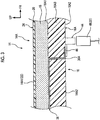
FIG. 1 is an enlarged sectional view (sectional view taken along line I-I inFIG. 4 ) illustrating a configuration of a main part of an instrument panel according to a first embodiment as seen in a vehicle front-rear direction; -
FIG. 2 is a plan view illustrating a configuration of the instrument panel according to the first embodiment; -
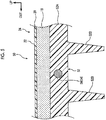
FIG. 3 is an enlarged sectional view (sectional view taken along line III-III inFIG. 4 ) illustrating a configuration of the main part of the instrument panel according to the first embodiment as seen in a vehicle width direction; -
FIG. 4 is a perspective view illustrating a configuration inside a vehicle cabin of a vehicle according to the first embodiment; and -
FIG. 5 is an enlarged sectional view illustrating a configuration of a main part of an instrument panel according to a second embodiment as seen in the vehicle front-rear direction. - Hereinafter, an interior member for a vehicle according to a first embodiment of the invention will be described by using
FIGS. 1 to 4 . An arrow FR appropriately shown in the drawings represents a vehicle front side, an arrow UP represents a vehicle upper side, and an arrow OUT represents an outer side in a vehicle width direction. - As illustrated in
FIG. 4 , aninstrument panel 14 as the interior member for a vehicle is disposed on the vehicle front side in a "vehicle cabin 12" of a "vehicle 10". Theinstrument panel 14 is configured to include an instrument panelupper portion 14A that constitutes a vehicle upper side portion of theinstrument panel 14 and extends in the vehicle width direction and a vehicle front-rear direction, an instrument panellower portion 14B that is provided to face a driver's seat (not shown), and an instrument panellower portion 14C that is provided to face a passenger seat (not shown). - Hereinafter, the configuration of the
instrument panel 14 will be described in more detail by using the configuration of the instrument panelupper portion 14A as an example. As illustrated inFIG. 1 , theinstrument panel 14 is configured to include a "base material 16" formed of a resin, a "foam layer 18" configured with foamed resin such as polyurethane, and a "cover material 20" configured with synthetic leather or the like. Regarding thebase material 16, the major portion of thebase material 16 is configured with amain body portion 16A formed in a plate-like shape and a "front surface 16A1" of themain body portion 16A is covered with thefoam layer 18 and thecover material 20, the front surface 16A1 being positioned close to adesign surface 22 in thevehicle cabin 12. Hereinafter, a portion configured with thecover material 20 and thefoam layer 18 will be referred to as a "front surface portion 24". A rear surface 16A2 of themain body portion 16A is provided with a plurality of "rib portions 16B" that protrudes in a thickness direction of themain body portion 16A from the rear surface 16A2 that is opposite to the front surface 16A1. - Each
rib portion 16B illustrated inFIG. 1 has a plate-like shape extending in the vehicle front-rear direction, for example. However, eachrib portion 16B may have a plate-like shape extending in a direction other than the vehicle front-rear direction and may be formed to have a grid shape as seen from the thickness direction of themain body portion 16A. - The
foam layer 18 is provided along the front surface 16A1 of themain body portion 16A of thebase material 16 in a state where the thickness thereof is constant and is in close contact with thebase material 16. A portion of thefoam layer 18 that is on thedesign surface 22 side is covered by the sheet-shapedcover material 20 constituting a portion of thedesign surface 22 and is in close contact with thecover material 20. - Referring again to
FIG. 4 , a plurality of electrical components is disposed on an upper surface 14A1 (portion of design surface 22) of the instrument panelupper portion 14A that is on the vehicle upper side. Specifically, a "head-updisplay 26" is disposed on a portion of the upper surface 14A1 of the instrument panelupper portion 14A that is positioned behind the central portion of the upper surface 14A1 in the vehicle front-rear direction. A "beacon sensor 28" and an "auto-light sensor 30" are disposed on a portion of the upper surface 14A1 of that is positioned ahead of the central portion of the upper surface 14A1 in the vehicle front-rear direction. A "speaker 32" is disposed on a portion the upper surface 14A1 that is positioned on an outer side in the vehicle width direction. - The first embodiment has a feature that a portion (hereinafter, referred to as "base material upper portion 16A3") of the
main body portion 16A of thebase material 16 that constitutes the instrument panelupper portion 14A is integrated with a "conductive portion 34" through which power is supplied to the electrical components disposed on the upper surface 14A1 of the instrument panelupper portion 14A as illustrated inFIG. 1 . Hereinafter, the configuration of theconductive portion 34 which is a main part of the first embodiment will be described in detail. - The
conductive portion 34 is formed of a metal. More specifically, theconductive portion 34 is formed of an alloy of tin and zinc or copper. Theconductive portion 34 and thebase material 16 are formed into an integrated molded product through two-color molding. That is, as resin constituting thebase material 16, resin of which the melting point is approximately the same as that of metal constituting theconductive portion 34 is used and examples of the resin constituting thebase material 16 include super engineering plastic such as polyimide. - As illustrated in
FIG. 2 , theconductive portion 34 is provided with alinear portion 36, alinear portion 38, alinear portion 40, and alinear portion 42 and thelinear portion 36, thelinear portion 38, thelinear portion 40, and thelinear portion 42 are formed to be linear as seen in a vehicle height direction. A portion of each of thelinear portion 36, thelinear portion 38, thelinear portion 40, and thelinear portion 42 that is opposite to thedesign surface 22 is in close contact with the base material upper portion 16A3 and a portion of each of thelinear portion 36, thelinear portion 38, thelinear portion 40, and thelinear portion 42 that is on thedesign surface 22 side faces thefoam layer 18. In the first embodiment, a portion of each of thelinear portion 36, thelinear portion 38, thelinear portion 40, and thelinear portion 42 that is on thedesign surface 22 side is in close contact with thefoam layer 18. However, a gap may be present between the above-described portion and thefoam layer 18. In a state where thecover material 20 and thefoam layer 18 are not attached to thebase material 16, theconductive portion 34 can be visually recognized as seen from the vehicle upper side. - More specifically, the
linear portion 36, thelinear portion 38, thelinear portion 40, and thelinear portion 42 extend to corresponding electrical components starting from the central portion of the base material upper portion 16A3 as seen from the vehicle upper side. Power can be supplied to thespeaker 32 through thelinear portion 36, can be supplied to thebeacon sensor 28 through thelinear portion 38, can be supplied to the auto-light sensor 30 through thelinear portion 40, and can be supplied to the head-updisplay 26 through thelinear portion 42. The thickness (sectional shape as seen in direction in which linear portions extend) of each of thelinear portion 36, thelinear portion 38, thelinear portion 40, and thelinear portion 42 may be appropriately changed according to power needed for the corresponding electrical component. - The configuration of connection points between the
conductive portion 34 and the electrical components will be described by using thelinear portion 36 as an example. As illustrated inFIG. 3 , thelinear portion 36 extends toward a vehicle lower side while passing through the base material upper portion 16A3 at the vicinity of thespeaker 32 and a portion thereof is exposed as seen from the vehicle lower side at a position close to a lower surface 14A2 of the instrument panelupper portion 14A that is opposite to the upper surface 14A1 (hereinafter, above-described portion will be described as "exposedportion 36A"). The lower surface 14A2 of the instrument panelupper portion 14A is provided with aconnector 44 and aterminal portion 46 of theconnector 44 and the exposedportion 36A are bonded to each other such that thelinear portion 36 and theconnector 44 are electrically connected to each other. Aconnector 48 of thespeaker 32 can be connected to theconnector 44 and power from an in-vehicle power source such as a battery (not shown) can be supplied to thespeaker 32 through thelinear portion 36. - The starting point (not shown) of each of the
linear portion 36, thelinear portion 38, thelinear portion 40, and thelinear portion 42 extends to the vehicle lower side while passing through the base material upper portion 16A3 at the central portion of the base material upper portion 16A3 and a portion thereof is exposed as seen from the vehicle lower side at a position close to the lower surface 14A2 of the instrument panelupper portion 14A. The central portion of the lower surface 14A2 is provided with a connector (not shown) and the connector is electrically connected to the portion of the starting point of each of thelinear portion 36, thelinear portion 38, thelinear portion 40, and thelinear portion 42 that is exposed as seen from the vehicle lower side. A connector (not shown) of a wire harness electrically connected to the in-vehicle power source is connected to the connector and power from the in-vehicle power source can be supplied to thelinear portion 36, thelinear portion 38, thelinear portion 40, and thelinear portion 42 through the connector. A portion of theconductive portion 34 that is not covered with thefront surface portion 24 and is not used for connection to the connector is covered with an insulation film. - The operation and the effect of the first embodiment will be described.
- In the case of the first embodiment, the
base material 16 formed of a resin and thefront surface portion 24 constituting a portion of thedesign surface 22 in thevehicle cabin 12 are provided and thefront surface portion 24 covers the front surface 16A1 of thebase material 16 that is on thedesign surface 22 side. - It is conceivable to route the wire harness or the like connected to the electrical components along the rear surface 16A2 of the
base material 16 that is opposite to the design surface of theinstrument panel 14 in order to secure the design of the inside of thevehicle cabin 12 when disposing the electrical components in thevehicle cabin 12. When the configuration as described above is adopted, it may be difficult to secure the degree of freedom in designing a portion of thebase material 16 that is opposite to the design surface of theinstrument panel 14 and the vicinity thereof. - In the case of the first embodiment, the
conductive portion 34 formed of a metal is integrally provided with thebase material 16 and it is possible to supply power to the electrical components installed in thevehicle 10 through theconductive portion 34 without routing the wire harness or the like in the vicinity of thebase material 16. Theconductive portion 34 is provided in thebase material 16 in a state where a portion of theconductive portion 34 that is opposite to thedesign surface 22 is in close contact with thebase material 16 and a portion of theconductive portion 34 that is on thedesign surface 22 side faces thefront surface portion 24 and theconductive portion 34 and thebase material 16 can be formed through two-color molding. Therefore, even when thebase material 16 is provided with theconductive portion 34, the influence of theconductive portion 34 on the configuration of a portion of thebase material 16 that is opposite to thedesign surface 22 can be further suppressed. - In the case of the first embodiment, it is possible to supply power to the electrical components without routing the wire harness or the like along the rear surface 16A2 of the
base material 16 and it is possible to secure the degree of freedom in designing a portion of theinstrument panel 14 that is opposite to thedesign surface 22 and the vicinity thereof. Specifically, it is possible to provide therib portions 16B or the like on the portion of theinstrument panel 14 that is opposite to thedesign surface 22 and it is possible to secure a space in which various electrical components are disposed on a side of theinstrument panel 14 that is opposite to thedesign surface 22. - In the case of the first embodiment, the
base material 16 and theconductive portion 34 are formed through two-color molding and constitute an integrated molded product. Therefore, it is possible to simplify an operation of mounting theinstrument panel 14 and to improve the degree of freedom in designing theinstrument panel 14 in comparison with a case where thebase material 16 and theconductive portion 34 are configured separately from each other. Therefore, in the case of the first embodiment, it is possible to improve the degree of freedom in designing thedesign surface 22 in thevehicle cabin 12 while reducing the number of processes for assembling thevehicle cabin 12. - In the case of the first embodiment, the
base material 16 is provided with therib portions 16B and therib portions 16B protrude from the rear surface 16A2 of thebase material 16 that is opposite to thedesign surface 22. Therefore, it is possible to reinforce thebase material 16 with therib portions 16B without an influence on the design surface of theinstrument panel 14. Accordingly, in the case of the first embodiment, it is possible to secure the design of the design surface of theinstrument panel 14 and to stably support a load that is applied to the design surface from the inside of thevehicle cabin 12 when the design surface is pressed by an occupant. - In the case of the first embodiment, a portion of the
conductive portion 34 is exposed at a surface of thebase material 16 that is opposite to thedesign surface 22 and the electrical components disposed in thevehicle cabin 12 can be connected to theconductive portion 34 at a portion of thebase material 16 that is opposite to thedesign surface 22. Therefore, in the case of the first embodiment, it is possible to effectively use a space in the vicinity of theinstrument panel 14 since connection points of the electrical components are set in the vicinity of theinstrument panel 14. - In the case of the first embodiment, the
base material 16 provided with theconductive portion 34 constitutes a portion of theinstrument panel 14 and thefront surface portion 24 is configured to include thefoam layer 18 that is in close contact with thebase material 16 while being disposed on a portion of thebase material 16 that is on thedesign surface 22 side and thecover material 20 that constitutes thedesign surface 22 and is in close contact with thefoam layer 18. Therefore, it is possible to further improve the design and texture of theinstrument panel 14 and it is possible to use theconductive portion 34 when supplying power to the electrical components disposed in the vicinity of theinstrument panel 14. Therefore, in the case of the first embodiment, it is possible to make theinstrument panel 14 look luxurious and it is possible to simplify an operation of attaching the electrical components in the vicinity of theinstrument panel 14. - Hereinafter, an interior member for a vehicle according to a second embodiment of the invention will be described by using
FIG. 5 . The same components as those in the first embodiment will be given the same reference numerals and description thereof will be omitted. - Basically, an
instrument panel 50 as the interior member for a vehicle according to the second embodiment is configured in the same manner as theinstrument panel 14. However, theinstrument panel 50 has a feature in a point that a "conductive portion 54" formed of a metal is built into amain body portion 52A of a "base material 52". - The
conductive portion 54 is configured to include linear portions respectively corresponding to thelinear portion 36, thelinear portion 38, thelinear portion 40, and thelinear portion 42 and theconductive portion 54 is integrally molded with thebase material 52 through insert molding. As metal constituting theconductive portion 54, metal of which the melting point is higher than the melting point of resin constituting thebase material 52 is used. For example, alinear portion 56 that corresponds to thelinear portion 36 is illustrated inFIG. 5 . - The
conductive portion 54 may be configured by pouring molten metal into thebase material 52 formed with a cavity portion. In a case where the above described manufacturing method is adopted, metal of which the melting point is lower than the melting point of resin constituting thebase material 52 is used as metal constituting theconductive portion 54. As with thebase material 16, thebase material 52 is provided with a plurality of "rib portions 52B". - With the above-described configuration, it is possible to achieve the same operation and effect as those in the first embodiment, excluding an operation and an effect achieved by a fact that the
base material 16 and theconductive portion 34 are formed through two-color molding. - In the case of the second embodiment, the
conductive portion 54 is built into thebase material 52 and the influence of theconductive portion 54 on the configuration of a portion of thebase material 52 that is close to thedesign surface 22 in thevehicle cabin 12 and a portion of thebase material 52 that is opposite to thedesign surface 22 can be further suppressed. - In the embodiments, the
instrument panel 14 and theinstrument panel 50 have been used examples of the interior member for a vehicle. However, a door trim or the like may have the same configuration as theinstrument panel 14 and theinstrument panel 50 such that the door trim or the like is provided with theconductive portion 34 or theconductive portion 54. - In the embodiments, the
front surface portion 24 is configured to include thefoam layer 18 and thecover material 20. However, thefront surface portion 24 may be configured with thecover material 20 alone corresponding to the disposition position or the like of the interior member for a vehicle. - In the embodiments, the interior member for a vehicle is provided with the
conductive portion 34 or theconductive portion 54. However, the interior member for a vehicle may be provided with theconductive portion 34 and theconductive portion 54 corresponding to the disposition positions or the like of the electrical components. - In the first embodiment, the
conductive portion 34 and thebase material 16 are provided through two-color molding. However, various manufacturing methods can be utilized corresponding to the configuration or the like of theinstrument panel 14. For example, theconductive portion 34 and thebase material 16 may be formed through insert molding and a configuration in which theconductive portion 34 and thebase material 16 are configured separately from each other and theconductive portion 34 is fitted into a groove portion provided in thebase material 16 may also be adopted.
Claims (6)
- An interior member for a vehicle (10), the interior member comprising:a base material (16) formed of a resin;a front surface portion (24) configured to constitute a portion of a design surface (22) in a vehicle cabin (12) and cover a surface (16A1) of the base material (16) that is on the design surface (22) side; anda conductive portion (34) integrally provided with the base material (16), a portion of the conductive portion (34) that is opposite to the design surface (22) being in close contact with the base material (16), a portion of the conductive portion (34) that is on the design surface (22) side facing the front surface portion (24), the conductive portion (34) being formed of a metal and being configured to conduct electric power to be supplied to an electrical component installed in the vehicle (10).
- The interior member according to claim 1, wherein the base material (16) and the conductive portion (34) are formed through two-color molding and constitute an integrated molded product.
- An interior member for a vehicle (10), the interior member comprising:a base material (52) formed of a resin;a front surface portion (24) configured to constitute a portion of a design surface (22) in a vehicle cabin (12) and cover a surface of the base material (52) that is on the design surface (22) side; anda conductive portion (54) built into the base material (52), the conductive portion (54) being formed of a metal and being configured to conduct electric power to be supplied to an electrical component installed in the vehicle (10).
- The interior member according to any one of claims 1 to 3, wherein the base material (16; 52) is provided with a rib portion (16B; 52B) that protrudes from a surface (16A2) of the base material (16; 52) that is opposite to the design surface (22).
- The interior member according to any one of claims 1 to 4, wherein a portion of the conductive portion (34) is exposed at a surface (16A2) of the base material (16) that is opposite to the design surface (22).
- The interior member according to any one of claims 1 to 5, wherein:the base material (16; 52) constitutes a portion of an instrument panel (14; 50); andthe front surface portion (24) includesa foam layer (18) that is in close contact with the base material (16; 52) while being disposed on a portion of the base material (16; 52) that is on the design surface (22) side, anda cover material (20) that constitutes the design surface (22) and is in close contact with the foam layer (18).
Applications Claiming Priority (1)
| Application Number | Priority Date | Filing Date | Title |
|---|---|---|---|
| JP2017234498A JP2019099053A (en) | 2017-12-06 | 2017-12-06 | Interior member for vehicle |
Publications (2)
| Publication Number | Publication Date |
|---|---|
| EP3495212A1 true EP3495212A1 (en) | 2019-06-12 |
| EP3495212B1 EP3495212B1 (en) | 2022-01-05 |
Family
ID=64650147
Family Applications (1)
| Application Number | Title | Priority Date | Filing Date |
|---|---|---|---|
| EP18210540.3A Not-in-force EP3495212B1 (en) | 2017-12-06 | 2018-12-05 | Interior member for vehicle |
Country Status (7)
| Country | Link |
|---|---|
| US (1) | US10850682B2 (en) |
| EP (1) | EP3495212B1 (en) |
| JP (1) | JP2019099053A (en) |
| KR (1) | KR20190067092A (en) |
| CN (1) | CN109878430B (en) |
| BR (1) | BR102018073929A2 (en) |
| RU (1) | RU2693587C1 (en) |
Cited By (1)
| Publication number | Priority date | Publication date | Assignee | Title |
|---|---|---|---|---|
| EP4484225A1 (en) * | 2023-06-30 | 2025-01-01 | SMRC Automotive Holdings Netherlands B.V. | Interior trim part for vehicles and method for manufacturing such a part |
Citations (8)
| Publication number | Priority date | Publication date | Assignee | Title |
|---|---|---|---|---|
| JPS63166508A (en) * | 1986-12-27 | 1988-07-09 | Honda Motor Co Ltd | Assembly of electronic trim part for vehicle |
| JPH06334305A (en) * | 1993-05-25 | 1994-12-02 | Res Dev Corp Of Japan | Method for forming conductive circuit by metal injection |
| JPH08216733A (en) | 1995-02-10 | 1996-08-27 | Toyota Motor Corp | Electrical component assembly and method of manufacturing the same |
| JPH10136541A (en) * | 1996-09-05 | 1998-05-22 | Harness Sogo Gijutsu Kenkyusho:Kk | Body mounting structure for wire harness |
| US6106303A (en) * | 1998-05-27 | 2000-08-22 | Lear Automotive Dearborn, Inc. | Trim panel having grooves with integrally formed electrical circuits |
| JP2001301546A (en) * | 2000-04-19 | 2001-10-31 | Inoac Corp | Vehicle interior parts |
| US20020041110A1 (en) * | 2000-07-10 | 2002-04-11 | Sumitomo Wiring Systems, Ltd. | Vehicle inner circuit panel, vehicle panel assembly and vehicle panel assembly wirign construction |
| US6428081B1 (en) * | 1999-04-28 | 2002-08-06 | Cadillac Products, Inc. | Water shield having integrated wiring |
Family Cites Families (14)
| Publication number | Priority date | Publication date | Assignee | Title |
|---|---|---|---|---|
| JPH055087Y2 (en) | 1986-02-18 | 1993-02-09 | ||
| DE3620881A1 (en) * | 1986-06-21 | 1988-01-14 | Audi Ag | Interior trim element for the passenger compartment of a motor vehicle |
| JPS6349556A (en) * | 1986-08-19 | 1988-03-02 | Honda Motor Co Ltd | Vehicle interior body |
| US5533748A (en) * | 1994-12-01 | 1996-07-09 | Morton International, Inc. | Invisible instrument panel or dashboard airbag cover door |
| US5705104A (en) * | 1996-05-10 | 1998-01-06 | Ford Motor Company | Method for embedding conductors in a structure |
| JP2000203311A (en) * | 1999-01-18 | 2000-07-25 | Toyo Tire & Rubber Co Ltd | instrument panel |
| JP3459885B2 (en) | 1999-04-20 | 2003-10-27 | 西川化成株式会社 | Instrument panel for vehicles |
| JP2001088578A (en) * | 1999-09-28 | 2001-04-03 | Mitsuboshi Belting Ltd | Instrument panel |
| DE10125074B4 (en) * | 2001-05-14 | 2006-04-13 | Faurecia Innenraum Systeme Gmbh | Interior trim part and method for its production |
| FR2868025B1 (en) * | 2004-03-26 | 2006-05-12 | Faurecia Interieur Ind Snc | INTERIOR VEHICLE CLOSURE ELEMENT AND METHOD FOR MAKING THE SAME |
| RU68968U1 (en) * | 2007-02-13 | 2007-12-10 | Открытое акционерное общество "АВТОВАЗ" | PANEL INSTRUMENTS FOR PASSENGER CAR |
| JP6056051B2 (en) * | 2013-04-17 | 2017-01-11 | トヨタ車体株式会社 | Instrument panel and manufacturing method thereof |
| RU134489U1 (en) * | 2013-05-06 | 2013-11-20 | Артем Александрович Морозов | ANTI-DIGITAL COVER ON THE DASHBOARD OF THE CAR |
| WO2017165294A1 (en) | 2016-03-21 | 2017-09-28 | Shanghai Yanfeng Jinqiao Automotive Trim Systems Co. Ltd | Vehicle interior component |
-
2017
- 2017-12-06 JP JP2017234498A patent/JP2019099053A/en active Pending
-
2018
- 2018-11-22 BR BR102018073929-8A patent/BR102018073929A2/en not_active IP Right Cessation
- 2018-11-22 RU RU2018141093A patent/RU2693587C1/en active
- 2018-11-28 KR KR1020180150115A patent/KR20190067092A/en not_active Ceased
- 2018-11-30 US US16/205,273 patent/US10850682B2/en active Active
- 2018-12-05 CN CN201811476370.7A patent/CN109878430B/en not_active Expired - Fee Related
- 2018-12-05 EP EP18210540.3A patent/EP3495212B1/en not_active Not-in-force
Patent Citations (8)
| Publication number | Priority date | Publication date | Assignee | Title |
|---|---|---|---|---|
| JPS63166508A (en) * | 1986-12-27 | 1988-07-09 | Honda Motor Co Ltd | Assembly of electronic trim part for vehicle |
| JPH06334305A (en) * | 1993-05-25 | 1994-12-02 | Res Dev Corp Of Japan | Method for forming conductive circuit by metal injection |
| JPH08216733A (en) | 1995-02-10 | 1996-08-27 | Toyota Motor Corp | Electrical component assembly and method of manufacturing the same |
| JPH10136541A (en) * | 1996-09-05 | 1998-05-22 | Harness Sogo Gijutsu Kenkyusho:Kk | Body mounting structure for wire harness |
| US6106303A (en) * | 1998-05-27 | 2000-08-22 | Lear Automotive Dearborn, Inc. | Trim panel having grooves with integrally formed electrical circuits |
| US6428081B1 (en) * | 1999-04-28 | 2002-08-06 | Cadillac Products, Inc. | Water shield having integrated wiring |
| JP2001301546A (en) * | 2000-04-19 | 2001-10-31 | Inoac Corp | Vehicle interior parts |
| US20020041110A1 (en) * | 2000-07-10 | 2002-04-11 | Sumitomo Wiring Systems, Ltd. | Vehicle inner circuit panel, vehicle panel assembly and vehicle panel assembly wirign construction |
Cited By (2)
| Publication number | Priority date | Publication date | Assignee | Title |
|---|---|---|---|---|
| EP4484225A1 (en) * | 2023-06-30 | 2025-01-01 | SMRC Automotive Holdings Netherlands B.V. | Interior trim part for vehicles and method for manufacturing such a part |
| FR3150483A1 (en) * | 2023-06-30 | 2025-01-03 | Smrc Automotive Holdings Netherlands B.V. | Interior trim part for vehicles and method of manufacturing such a part |
Also Published As
| Publication number | Publication date |
|---|---|
| KR20190067092A (en) | 2019-06-14 |
| EP3495212B1 (en) | 2022-01-05 |
| US20190168689A1 (en) | 2019-06-06 |
| JP2019099053A (en) | 2019-06-24 |
| CN109878430B (en) | 2022-09-23 |
| US10850682B2 (en) | 2020-12-01 |
| CN109878430A (en) | 2019-06-14 |
| BR102018073929A2 (en) | 2019-06-25 |
| RU2693587C1 (en) | 2019-07-03 |
Similar Documents
| Publication | Publication Date | Title |
|---|---|---|
| US8656804B2 (en) | Steering wheel and steering apparatus | |
| US20010037607A1 (en) | Door module for motor vehicles with plastic functional components | |
| CN112208477A (en) | Crash pad including airbag door opening | |
| CN113382890B (en) | Wiring module for vehicle door and method for manufacturing wiring module for vehicle door | |
| US6949709B1 (en) | Method for making a dashboard subassembly in paticular a motor vehicle dashboard console | |
| EP3495212A1 (en) | Interior member for vehicle | |
| CN109606277A (en) | Interior component for vehicle and vehicle | |
| US9084347B2 (en) | Power supply mounting structure and vehicle provided with same | |
| EP3383708B1 (en) | Interior trim components with integrated electrical wiring | |
| US20220009324A1 (en) | Attachment structure of door wiring module | |
| JP2012040953A (en) | Electrical system | |
| JP4379667B2 (en) | instrument panel | |
| KR100849288B1 (en) | Center stack for automotive instrument panel assembly, manufacturing method of center stack for instrument panel and car instrument panel center stack kit | |
| US9543684B1 (en) | Trim panel | |
| CN115515823B (en) | Wiring module | |
| JP2008125274A (en) | Wire harness protector | |
| US20260034859A1 (en) | Nterior equipment of a vehicle and a method of manufacturing the same | |
| JP7272169B2 (en) | Body side structure | |
| JP2008067583A (en) | Wire harness protector | |
| JP2025141317A (en) | Laying structure for additional wiring member | |
| AU2002235382A1 (en) | Instrument panel center stack with integrated wiring | |
| JP2009036234A (en) | Clip mounting structure | |
| CN120191301A (en) | Electric Vehicles | |
| JP2010034299A (en) | Shielding case | |
| JP2001301546A (en) | Vehicle interior parts |
Legal Events
| Date | Code | Title | Description |
|---|---|---|---|
| PUAI | Public reference made under article 153(3) epc to a published international application that has entered the european phase |
Free format text: ORIGINAL CODE: 0009012 |
|
| STAA | Information on the status of an ep patent application or granted ep patent |
Free format text: STATUS: REQUEST FOR EXAMINATION WAS MADE |
|
| 17P | Request for examination filed |
Effective date: 20181205 |
|
| AK | Designated contracting states |
Kind code of ref document: A1 Designated state(s): AL AT BE BG CH CY CZ DE DK EE ES FI FR GB GR HR HU IE IS IT LI LT LU LV MC MK MT NL NO PL PT RO RS SE SI SK SM TR |
|
| AX | Request for extension of the european patent |
Extension state: BA ME |
|
| STAA | Information on the status of an ep patent application or granted ep patent |
Free format text: STATUS: EXAMINATION IS IN PROGRESS |
|
| 17Q | First examination report despatched |
Effective date: 20200117 |
|
| GRAP | Despatch of communication of intention to grant a patent |
Free format text: ORIGINAL CODE: EPIDOSNIGR1 |
|
| STAA | Information on the status of an ep patent application or granted ep patent |
Free format text: STATUS: GRANT OF PATENT IS INTENDED |
|
| INTG | Intention to grant announced |
Effective date: 20210709 |
|
| GRAS | Grant fee paid |
Free format text: ORIGINAL CODE: EPIDOSNIGR3 |
|
| GRAA | (expected) grant |
Free format text: ORIGINAL CODE: 0009210 |
|
| STAA | Information on the status of an ep patent application or granted ep patent |
Free format text: STATUS: THE PATENT HAS BEEN GRANTED |
|
| AK | Designated contracting states |
Kind code of ref document: B1 Designated state(s): AL AT BE BG CH CY CZ DE DK EE ES FI FR GB GR HR HU IE IS IT LI LT LU LV MC MK MT NL NO PL PT RO RS SE SI SK SM TR |
|
| REG | Reference to a national code |
Ref country code: GB Ref legal event code: FG4D |
|
| REG | Reference to a national code |
Ref country code: CH Ref legal event code: EP |
|
| REG | Reference to a national code |
Ref country code: AT Ref legal event code: REF Ref document number: 1460252 Country of ref document: AT Kind code of ref document: T Effective date: 20220115 |
|
| REG | Reference to a national code |
Ref country code: DE Ref legal event code: R096 Ref document number: 602018029074 Country of ref document: DE |
|
| REG | Reference to a national code |
Ref country code: IE Ref legal event code: FG4D |
|
| REG | Reference to a national code |
Ref country code: LT Ref legal event code: MG9D |
|
| REG | Reference to a national code |
Ref country code: NL Ref legal event code: MP Effective date: 20220105 |
|
| REG | Reference to a national code |
Ref country code: AT Ref legal event code: MK05 Ref document number: 1460252 Country of ref document: AT Kind code of ref document: T Effective date: 20220105 |
|
| PG25 | Lapsed in a contracting state [announced via postgrant information from national office to epo] |
Ref country code: NL Free format text: LAPSE BECAUSE OF FAILURE TO SUBMIT A TRANSLATION OF THE DESCRIPTION OR TO PAY THE FEE WITHIN THE PRESCRIBED TIME-LIMIT Effective date: 20220105 |
|
| PG25 | Lapsed in a contracting state [announced via postgrant information from national office to epo] |
Ref country code: SE Free format text: LAPSE BECAUSE OF FAILURE TO SUBMIT A TRANSLATION OF THE DESCRIPTION OR TO PAY THE FEE WITHIN THE PRESCRIBED TIME-LIMIT Effective date: 20220105 Ref country code: RS Free format text: LAPSE BECAUSE OF FAILURE TO SUBMIT A TRANSLATION OF THE DESCRIPTION OR TO PAY THE FEE WITHIN THE PRESCRIBED TIME-LIMIT Effective date: 20220105 Ref country code: PT Free format text: LAPSE BECAUSE OF FAILURE TO SUBMIT A TRANSLATION OF THE DESCRIPTION OR TO PAY THE FEE WITHIN THE PRESCRIBED TIME-LIMIT Effective date: 20220505 Ref country code: NO Free format text: LAPSE BECAUSE OF FAILURE TO SUBMIT A TRANSLATION OF THE DESCRIPTION OR TO PAY THE FEE WITHIN THE PRESCRIBED TIME-LIMIT Effective date: 20220405 Ref country code: LT Free format text: LAPSE BECAUSE OF FAILURE TO SUBMIT A TRANSLATION OF THE DESCRIPTION OR TO PAY THE FEE WITHIN THE PRESCRIBED TIME-LIMIT Effective date: 20220105 Ref country code: HR Free format text: LAPSE BECAUSE OF FAILURE TO SUBMIT A TRANSLATION OF THE DESCRIPTION OR TO PAY THE FEE WITHIN THE PRESCRIBED TIME-LIMIT Effective date: 20220105 Ref country code: ES Free format text: LAPSE BECAUSE OF FAILURE TO SUBMIT A TRANSLATION OF THE DESCRIPTION OR TO PAY THE FEE WITHIN THE PRESCRIBED TIME-LIMIT Effective date: 20220105 Ref country code: BG Free format text: LAPSE BECAUSE OF FAILURE TO SUBMIT A TRANSLATION OF THE DESCRIPTION OR TO PAY THE FEE WITHIN THE PRESCRIBED TIME-LIMIT Effective date: 20220405 |
|
| PG25 | Lapsed in a contracting state [announced via postgrant information from national office to epo] |
Ref country code: PL Free format text: LAPSE BECAUSE OF FAILURE TO SUBMIT A TRANSLATION OF THE DESCRIPTION OR TO PAY THE FEE WITHIN THE PRESCRIBED TIME-LIMIT Effective date: 20220105 Ref country code: LV Free format text: LAPSE BECAUSE OF FAILURE TO SUBMIT A TRANSLATION OF THE DESCRIPTION OR TO PAY THE FEE WITHIN THE PRESCRIBED TIME-LIMIT Effective date: 20220105 Ref country code: GR Free format text: LAPSE BECAUSE OF FAILURE TO SUBMIT A TRANSLATION OF THE DESCRIPTION OR TO PAY THE FEE WITHIN THE PRESCRIBED TIME-LIMIT Effective date: 20220406 Ref country code: FI Free format text: LAPSE BECAUSE OF FAILURE TO SUBMIT A TRANSLATION OF THE DESCRIPTION OR TO PAY THE FEE WITHIN THE PRESCRIBED TIME-LIMIT Effective date: 20220105 Ref country code: AT Free format text: LAPSE BECAUSE OF FAILURE TO SUBMIT A TRANSLATION OF THE DESCRIPTION OR TO PAY THE FEE WITHIN THE PRESCRIBED TIME-LIMIT Effective date: 20220105 |
|
| PG25 | Lapsed in a contracting state [announced via postgrant information from national office to epo] |
Ref country code: IS Free format text: LAPSE BECAUSE OF FAILURE TO SUBMIT A TRANSLATION OF THE DESCRIPTION OR TO PAY THE FEE WITHIN THE PRESCRIBED TIME-LIMIT Effective date: 20220505 |
|
| REG | Reference to a national code |
Ref country code: DE Ref legal event code: R097 Ref document number: 602018029074 Country of ref document: DE |
|
| PG25 | Lapsed in a contracting state [announced via postgrant information from national office to epo] |
Ref country code: SM Free format text: LAPSE BECAUSE OF FAILURE TO SUBMIT A TRANSLATION OF THE DESCRIPTION OR TO PAY THE FEE WITHIN THE PRESCRIBED TIME-LIMIT Effective date: 20220105 Ref country code: SK Free format text: LAPSE BECAUSE OF FAILURE TO SUBMIT A TRANSLATION OF THE DESCRIPTION OR TO PAY THE FEE WITHIN THE PRESCRIBED TIME-LIMIT Effective date: 20220105 Ref country code: RO Free format text: LAPSE BECAUSE OF FAILURE TO SUBMIT A TRANSLATION OF THE DESCRIPTION OR TO PAY THE FEE WITHIN THE PRESCRIBED TIME-LIMIT Effective date: 20220105 Ref country code: EE Free format text: LAPSE BECAUSE OF FAILURE TO SUBMIT A TRANSLATION OF THE DESCRIPTION OR TO PAY THE FEE WITHIN THE PRESCRIBED TIME-LIMIT Effective date: 20220105 Ref country code: DK Free format text: LAPSE BECAUSE OF FAILURE TO SUBMIT A TRANSLATION OF THE DESCRIPTION OR TO PAY THE FEE WITHIN THE PRESCRIBED TIME-LIMIT Effective date: 20220105 Ref country code: CZ Free format text: LAPSE BECAUSE OF FAILURE TO SUBMIT A TRANSLATION OF THE DESCRIPTION OR TO PAY THE FEE WITHIN THE PRESCRIBED TIME-LIMIT Effective date: 20220105 |
|
| PLBE | No opposition filed within time limit |
Free format text: ORIGINAL CODE: 0009261 |
|
| STAA | Information on the status of an ep patent application or granted ep patent |
Free format text: STATUS: NO OPPOSITION FILED WITHIN TIME LIMIT |
|
| PG25 | Lapsed in a contracting state [announced via postgrant information from national office to epo] |
Ref country code: AL Free format text: LAPSE BECAUSE OF FAILURE TO SUBMIT A TRANSLATION OF THE DESCRIPTION OR TO PAY THE FEE WITHIN THE PRESCRIBED TIME-LIMIT Effective date: 20220105 |
|
| 26N | No opposition filed |
Effective date: 20221006 |
|
| PGFP | Annual fee paid to national office [announced via postgrant information from national office to epo] |
Ref country code: DE Payment date: 20221102 Year of fee payment: 5 |
|
| PG25 | Lapsed in a contracting state [announced via postgrant information from national office to epo] |
Ref country code: SI Free format text: LAPSE BECAUSE OF FAILURE TO SUBMIT A TRANSLATION OF THE DESCRIPTION OR TO PAY THE FEE WITHIN THE PRESCRIBED TIME-LIMIT Effective date: 20220105 |
|
| P01 | Opt-out of the competence of the unified patent court (upc) registered |
Effective date: 20230427 |
|
| REG | Reference to a national code |
Ref country code: DE Ref legal event code: R084 Ref document number: 602018029074 Country of ref document: DE |
|
| PG25 | Lapsed in a contracting state [announced via postgrant information from national office to epo] |
Ref country code: IT Free format text: LAPSE BECAUSE OF FAILURE TO SUBMIT A TRANSLATION OF THE DESCRIPTION OR TO PAY THE FEE WITHIN THE PRESCRIBED TIME-LIMIT Effective date: 20220105 |
|
| REG | Reference to a national code |
Ref country code: CH Ref legal event code: PL |
|
| GBPC | Gb: european patent ceased through non-payment of renewal fee |
Effective date: 20221205 |
|
| REG | Reference to a national code |
Ref country code: BE Ref legal event code: MM Effective date: 20221231 |
|
| PG25 | Lapsed in a contracting state [announced via postgrant information from national office to epo] |
Ref country code: LU Free format text: LAPSE BECAUSE OF NON-PAYMENT OF DUE FEES Effective date: 20221205 |
|
| PG25 | Lapsed in a contracting state [announced via postgrant information from national office to epo] |
Ref country code: LI Free format text: LAPSE BECAUSE OF NON-PAYMENT OF DUE FEES Effective date: 20221231 Ref country code: IE Free format text: LAPSE BECAUSE OF NON-PAYMENT OF DUE FEES Effective date: 20221205 Ref country code: GB Free format text: LAPSE BECAUSE OF NON-PAYMENT OF DUE FEES Effective date: 20221205 Ref country code: CH Free format text: LAPSE BECAUSE OF NON-PAYMENT OF DUE FEES Effective date: 20221231 |
|
| PG25 | Lapsed in a contracting state [announced via postgrant information from national office to epo] |
Ref country code: FR Free format text: LAPSE BECAUSE OF NON-PAYMENT OF DUE FEES Effective date: 20221231 Ref country code: BE Free format text: LAPSE BECAUSE OF NON-PAYMENT OF DUE FEES Effective date: 20221231 |
|
| PG25 | Lapsed in a contracting state [announced via postgrant information from national office to epo] |
Ref country code: HU Free format text: LAPSE BECAUSE OF FAILURE TO SUBMIT A TRANSLATION OF THE DESCRIPTION OR TO PAY THE FEE WITHIN THE PRESCRIBED TIME-LIMIT; INVALID AB INITIO Effective date: 20181205 |
|
| PG25 | Lapsed in a contracting state [announced via postgrant information from national office to epo] |
Ref country code: CY Free format text: LAPSE BECAUSE OF FAILURE TO SUBMIT A TRANSLATION OF THE DESCRIPTION OR TO PAY THE FEE WITHIN THE PRESCRIBED TIME-LIMIT Effective date: 20220105 |
|
| PG25 | Lapsed in a contracting state [announced via postgrant information from national office to epo] |
Ref country code: MK Free format text: LAPSE BECAUSE OF FAILURE TO SUBMIT A TRANSLATION OF THE DESCRIPTION OR TO PAY THE FEE WITHIN THE PRESCRIBED TIME-LIMIT Effective date: 20220105 |
|
| PG25 | Lapsed in a contracting state [announced via postgrant information from national office to epo] |
Ref country code: MC Free format text: LAPSE BECAUSE OF FAILURE TO SUBMIT A TRANSLATION OF THE DESCRIPTION OR TO PAY THE FEE WITHIN THE PRESCRIBED TIME-LIMIT Effective date: 20220105 |
|
| PG25 | Lapsed in a contracting state [announced via postgrant information from national office to epo] |
Ref country code: MC Free format text: LAPSE BECAUSE OF FAILURE TO SUBMIT A TRANSLATION OF THE DESCRIPTION OR TO PAY THE FEE WITHIN THE PRESCRIBED TIME-LIMIT Effective date: 20220105 |
|
| REG | Reference to a national code |
Ref country code: DE Ref legal event code: R119 Ref document number: 602018029074 Country of ref document: DE |
|
| PG25 | Lapsed in a contracting state [announced via postgrant information from national office to epo] |
Ref country code: MT Free format text: LAPSE BECAUSE OF FAILURE TO SUBMIT A TRANSLATION OF THE DESCRIPTION OR TO PAY THE FEE WITHIN THE PRESCRIBED TIME-LIMIT Effective date: 20220105 |
|
| PG25 | Lapsed in a contracting state [announced via postgrant information from national office to epo] |
Ref country code: DE Free format text: LAPSE BECAUSE OF NON-PAYMENT OF DUE FEES Effective date: 20240702 |
|
| PG25 | Lapsed in a contracting state [announced via postgrant information from national office to epo] |
Ref country code: DE Free format text: LAPSE BECAUSE OF NON-PAYMENT OF DUE FEES Effective date: 20240702 |
|
| PG25 | Lapsed in a contracting state [announced via postgrant information from national office to epo] |
Ref country code: TR Free format text: LAPSE BECAUSE OF FAILURE TO SUBMIT A TRANSLATION OF THE DESCRIPTION OR TO PAY THE FEE WITHIN THE PRESCRIBED TIME-LIMIT Effective date: 20220105 |