EP3495168A1 - Pneumatic tire - Google Patents
Pneumatic tire Download PDFInfo
- Publication number
- EP3495168A1 EP3495168A1 EP18196565.8A EP18196565A EP3495168A1 EP 3495168 A1 EP3495168 A1 EP 3495168A1 EP 18196565 A EP18196565 A EP 18196565A EP 3495168 A1 EP3495168 A1 EP 3495168A1
- Authority
- EP
- European Patent Office
- Prior art keywords
- bead
- tire
- rim
- axial direction
- outer side
- Prior art date
- Legal status (The legal status is an assumption and is not a legal conclusion. Google has not performed a legal analysis and makes no representation as to the accuracy of the status listed.)
- Granted
Links
Images


Classifications
-
- B—PERFORMING OPERATIONS; TRANSPORTING
- B60—VEHICLES IN GENERAL
- B60C—VEHICLE TYRES; TYRE INFLATION; TYRE CHANGING; CONNECTING VALVES TO INFLATABLE ELASTIC BODIES IN GENERAL; DEVICES OR ARRANGEMENTS RELATED TO TYRES
- B60C15/00—Tyre beads, e.g. ply turn-up or overlap
- B60C15/02—Seating or securing beads on rims
- B60C15/024—Bead contour, e.g. lips, grooves, or ribs
-
- B—PERFORMING OPERATIONS; TRANSPORTING
- B60—VEHICLES IN GENERAL
- B60C—VEHICLE TYRES; TYRE INFLATION; TYRE CHANGING; CONNECTING VALVES TO INFLATABLE ELASTIC BODIES IN GENERAL; DEVICES OR ARRANGEMENTS RELATED TO TYRES
- B60C15/00—Tyre beads, e.g. ply turn-up or overlap
-
- B—PERFORMING OPERATIONS; TRANSPORTING
- B60—VEHICLES IN GENERAL
- B60C—VEHICLE TYRES; TYRE INFLATION; TYRE CHANGING; CONNECTING VALVES TO INFLATABLE ELASTIC BODIES IN GENERAL; DEVICES OR ARRANGEMENTS RELATED TO TYRES
- B60C15/00—Tyre beads, e.g. ply turn-up or overlap
- B60C15/04—Bead cores
-
- B—PERFORMING OPERATIONS; TRANSPORTING
- B60—VEHICLES IN GENERAL
- B60C—VEHICLE TYRES; TYRE INFLATION; TYRE CHANGING; CONNECTING VALVES TO INFLATABLE ELASTIC BODIES IN GENERAL; DEVICES OR ARRANGEMENTS RELATED TO TYRES
- B60C15/00—Tyre beads, e.g. ply turn-up or overlap
- B60C15/02—Seating or securing beads on rims
- B60C15/024—Bead contour, e.g. lips, grooves, or ribs
- B60C2015/0245—Bead lips at the bead toe portion, i.e. the axially and radially inner end of the bead
-
- B—PERFORMING OPERATIONS; TRANSPORTING
- B60—VEHICLES IN GENERAL
- B60C—VEHICLE TYRES; TYRE INFLATION; TYRE CHANGING; CONNECTING VALVES TO INFLATABLE ELASTIC BODIES IN GENERAL; DEVICES OR ARRANGEMENTS RELATED TO TYRES
- B60C15/00—Tyre beads, e.g. ply turn-up or overlap
- B60C15/06—Flipper strips, fillers, or chafing strips and reinforcing layers for the construction of the bead
- B60C2015/0614—Flipper strips, fillers, or chafing strips and reinforcing layers for the construction of the bead characterised by features of the chafer or clinch portion, i.e. the part of the bead contacting the rim
-
- B—PERFORMING OPERATIONS; TRANSPORTING
- B60—VEHICLES IN GENERAL
- B60C—VEHICLE TYRES; TYRE INFLATION; TYRE CHANGING; CONNECTING VALVES TO INFLATABLE ELASTIC BODIES IN GENERAL; DEVICES OR ARRANGEMENTS RELATED TO TYRES
- B60C2200/00—Tyres specially adapted for particular applications
- B60C2200/10—Tyres specially adapted for particular applications for motorcycles, scooters or the like
Definitions
- Japanese Patent No. 4926314 discloses a technique for improving the engagement property between the bead portions and the rim.
- the distance (H) is larger than 0.8 times and smaller than 2.0 times the maximum width (Y).
- Each of the bead portions 4 in this embodiment includes the outer side surface (4a) and a bead bottom surface (4b) connected to the outer side surface (4a) and to be in contact with a base portion (Ra) of the rim (R).
- the outer side surfaces (4a) in this embodiment are to be in contact with flange portions (Rb) of the rim (R) positioned on an outer side in the tire radial direction of a bead base line (not shown) and extending in the tire radius direction.
- the distance (H) is larger than 0.8 times and smaller than 2.0 times the maximum width (Y). It is further preferred that the distance (H) is in the range of from 1.0 to 1.7 times the maximum width (Y).
- the maximum width (Y) is preferably in the range of from 4 to 10 mm, more preferably in the range of from 4.5 to 7.5 mm.
- Fig. 3 is a cross-sectional view of one of the bead portions 4A according to another embodiment.
- each of the bead cores 5 in this embodiment is formed to have a circular cross section, for example.
- Each of the bead cores 5 in this embodiment is formed by a cable bead 10.
- the cable bead 10 in this embodiment is formed of an annular core (11a) and one or more sheath wires (11b) wound helically around the annular core 11a.
- the bead portions 4 have preferred rigidity, therefore, the steering stability and the engagement property with the rim are improved in a good balance.
- the bead portions 4 in this embodiment include an inner liner 15, a tie gum layer 16, and chafer rubbers 17 arranged on the inner side in the tire axial direction of the bead cores 5.
- the tie gum layer 16 in this embodiment is disposed between the inner liner 15 and the main body portion (6a) of the carcass 6.
- the tie gum layer 16 in this embodiment extends from the inner side in the tire radial direction of the inner end (5a) of the bead core 5 to the outer side in the tire radial direction of an outer end (8a) of the bead apex rubber 8.
- the tie gum layer 16 in this embodiment has superior adhesiveness to the inner liner 15, and can effectively suppress separation between the inner liner 15 and the carcass 6.
- Each of the chafer rubbers 17 in this embodiment forms the inner cavity surface (1a), respective one of the outer side surfaces (4a), and respective one of the bead bottom surfaces (4b), and is formed in a substantially U-shape so as to surround respective one of the bead cores 5. It is possible that the chafer rubbers 17 prevent the displacement between the bead portions 4 and the rim (R).
- Pneumatic tires for a motorcycle of size 180/55ZR17 having the basic structure shown in Fig. 1 were made by way of test according to the specifications listed in Table 1, then the test tires were tested for the steering stability and the engagement property with the rim.
- the test methods were as follows.
- test tires were mounted on a rear wheel of a motorcycle with displacement of 1300 cc under the following conditions. Note that a commercial tire was mounted on a front wheel of the test motorcycle. Then, a test rider drove the test motorcycle on a dry asphalt road surface, and running characteristics related to steering response, rigid impression, grip force, etc. during cornering were evaluated by the test rider's feeling. The results are indicated by an evaluation point based on Reference 1 being 100 wherein a larger numerical value is better. It is judged as effective if there is a difference not less than 5 points as compared with the result of the Reference 1.
Landscapes
- Engineering & Computer Science (AREA)
- Mechanical Engineering (AREA)
- Tires In General (AREA)
Abstract
Description
- The present invention relates to a pneumatic tire having bead cores.
- Conventionally, in a pneumatic tire, due to a large lateral force exerted during cornering, bead portions displace in a tire axial direction on rims, therefore, steering stability is deteriorated, for example. In order to suppress such displacement of the bead portions, it is possible to increase the contact between the rim and the bead portions by increasing the tightening force onto the rim, for example.
- However, such a pneumatic tire has a problem that it is difficult to mount the bead portions on the rim, and engagement property between the bead portions and the rim is easily deteriorated. Note that Japanese Patent No.
4926314 - The present invention was made in view of the above, and a primary object thereof is to provide a pneumatic tire capable of improving engagement property between the bead portions and the rim and the steering stability in a good balance.
- In one aspect of the present invention, a pneumatic tire comprises a pair of bead portions each having a bead core therein, wherein each of the pair of the bead portions has an outer side surface which is to be in contact with a standard rim on an outer side in a tire axial direction of the respective one of the bead cores, in a tire meridian section of the pneumatic tire in a pre-mounted state in which a width between the outer side surfaces is equal to a rim width of the standard rim, in at least one of the pair of the bead portions, a distance (H) in a tire radial direction between an inner end in the tire radial direction of the bead core and a bead toe is larger than 0.5 times and smaller 2.5 times a maximum width (Y) in the tire axial direction of the bead core.
- In another aspect of the invention, it is preferred that a width in the tire axial direction of each of the bead cores increases radially outwardly from the inner end of respective one of the bead cores.
- In another aspect of the invention, it is preferred that the distance (H) is larger than 0.8 times and smaller than 2.0 times the maximum width (Y).
- In another aspect of the invention, it is preferred that a distance (x) between the inner end in the tire axial direction of the bead core and the bead toe is larger than 0.3 times and smaller than 2.0 times the maximum width (Y).
- In another aspect of the invention, it is preferred that a minimum length in the tire axial direction between the bead core and the outer side surface is in a range of from 10% to 25% of the maximum width (Y).
-
-
Fig. 1 is a cross-sectional view of a pneumatic tire in a pre-mounted state according to an embodiment of the present invention. -
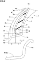
Fig. 2 is an enlarged view of one of bead portions ofFig. 1 . -
Fig. 3 is a cross-sectional view of one of the bead portions according to another embodiment of the present invention. -
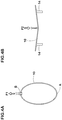
Fig. 4A is an explanatory diagram of a method of measuring in-plane rigidity of a cable bead. -
FIG. 4B is an explanatory diagram of a method of measuring out-of-plane rigidity of the cable bead. - An embodiment of the present invention will now be described below in detail in conjunction with accompanying drawings.
-
Fig. 1 is a tire meridian section passing through a tire rotational axis (not shown) of a pneumatic tire (hereinafter may be simply referred to as "tire") 1 according to an embodiment of the present invention in a pre-mounted state. In this embodiment, a tire for a motorcycle is shown as a preferred example of thetire 1. Note that thetire 1 of the present invention is not limited to a tire for a motorcycle. - The
tire 1 in this embodiment includes acarcass 6 extending betweenbead cores 5 ofbead portions 4 via atread portion 2 andsidewall portions 3, and abelt layer 7 arranged on an outer side in a tire radial direction of thecarcass 6. - The
carcass 6 is formed of at least one, one in this embodiment,carcass ply 6A. Thecarcass ply 6A includes a main body portion (6a) extending between a pair of thebead cores 5 in a toroidal manner and a pair of turned up portions (6b) arranged continuously to both ends of the main body portion (6a) and each turned up around respective one of thebead cores 5 from inside to outside in the tire axial direction.Bead apex rubber 8 for increasing rigidity of thebead portions 4 is provided between the main body portion (6a) and each of the turned up portions (6b). - The
belt layer 7 is arranged in the inside of thetread portion 2 and extends to the vicinity of the tread edges (Te) on both sides. Thebelt layer 7 in this embodiment is formed of twobelt plies - In the present specification, the " pre-mounted state " refers to a state in which the
bead portions 4 are held so that a distance between outer side surfaces (4a) of thebead portions 4 is equal to a rim width (wa) of a standard rim (hereinafter, may be simply referred to as "rim") (R), wherein the outer side surfaces (4a) are each to be in contact with the rim (R) on an outer side in the tire axial direction of respective one of thebead cores 5. Hereinafter, unless otherwise noted, dimensions and the like of various parts of thetire 1 are those measured in this pre-mounted state. - The "standard rim" is a wheel rim specified for the concerned tire by a standard included in a standardization system on which the tire is based, for example, the "normal wheel rim" in JATMA, "Design Rim" in TRA, and "Measuring Rim" in ETRTO.
- Each of the
bead portions 4 in this embodiment includes the outer side surface (4a) and a bead bottom surface (4b) connected to the outer side surface (4a) and to be in contact with a base portion (Ra) of the rim (R). The outer side surfaces (4a) in this embodiment are to be in contact with flange portions (Rb) of the rim (R) positioned on an outer side in the tire radial direction of a bead base line (not shown) and extending in the tire radius direction. - Each of the bead bottom surfaces (4b) in this embodiment includes a
bead toe 13 which is an innermost end in the tire radial direction and an innermost end in the tire axial direction of respective one of thebead portions 4 and extends obliquely and radially outwardly from thebead toe 13 toward the outer side in the tire axial direction. Each of the bead bottom surfaces (4b) in this embodiment is formed in a smooth arc shape convex toward the outer side in the tire radial direction. Each of the bead bottom surfaces (4b) is formed by a plurality of arcuate shapes with decreasing radii of curvature from thebead toe 13 toward the outer side in the tire axial direction, for example. Note that the bead bottom surfaces (4b) are not limited to such an embodiment. -
Fig. 2 is an enlarged view of one of thebead portions 4 ofFig. 1 . As shown inFig. 2 , in at least one of the pair of thebead portions 4, a distance (H) in the tire radial direction between an inner end (5a) in the tire radial direction of thebead core 5 and thebead toe 13 is larger than 0.5 times and smaller than 2.5 times a maximum width (Y) in the tire axial direction of thebead core 5. Thereby, a preferable rubber volume is given to a part positioned on the inner side in the tire radial direction of thebead core 5, therefore, it is possible that this rubber is sufficiently deformed. Therefore, it becomes easy for the tire to engage with the rim (R), and the engagement property with the rim is improved. Further, in thetire 1 configured as such, during cornering, in a part on a side of thebead portion 4 where displacement is likely to occur, in the tire meridian section, torque rotating around thebead core 5 from the side of the base portion (Ra) to the side of the flange portion (Rb) of the rim (R). Thereby, the rubber is pressed toward the side of the flange portion (Rb) of the rim (R), therefore, the contact between the rubber and the rim (R) is increased, thereby, the steering stability is improved. - when the distance (H) is not more than 0.5 times the maximum width (Y), the rubber volume of a part on the inner side in the tire radial direction of the
bead core 5 becomes small, therefore, the deformation of the rubber becomes small, thereby, the engagement property with the rim is deteriorated. When the distance (H) is not less than 2.5 times the maximum width (Y), the rubber volume becomes excessively large, therefore, the tightening force toward the flange portion (Rb) becomes small, thereby, the steering stability is deteriorated. - In this embodiment, in the
bead portions 4 on both sides, the distance (H) is set to be larger than 0.5 times and smaller than 2.5 times the maximum width (Y). - In order to effectively exert the above-mentioned effects, it is preferred that the distance (H) is larger than 0.8 times and smaller than 2.0 times the maximum width (Y). It is further preferred that the distance (H) is in the range of from 1.0 to 1.7 times the maximum width (Y).
- In each of the
bead portions 4, it is preferred that a distance (x) in the tire axial direction between an inner end (5i) in the tire axial direction of thebead core 5 and thebead toe 13 is larger than 0.3 times and smaller than 2.0 times the maximum width (Y). When the distance (X) is not more than 0.3 times the maximum width (Y), the rubber volume of the part on the inner side in the tire axial direction of thebead core 5 becomes small, therefore, frictional force between the rubber and the base portion (Ra) becomes small. Thereby, during cornering, in the part on the side of thebead portion 4 where the displacement is likely to occur, it is possible that the displacement is caused by the torque. When the distance (X) is not less than 2.0 times the maximum width (Y), the rubber volume of the part on the inner side in the tire axial direction of thebead core 5 becomes excessively large, therefore, at the time of engagement with the rim (R), the frictional force between the rim (R) and the rubber on the inner side in the tire axial direction becomes large, thereby, it becomes difficult to engage with each other. In order to improve the engagement property with the rim and the steering stability in a good balance, it is further preferred that the distance (X) is in the range of from 0.8 to 1.5 times the maximum width (Y). - In each of the
bead portions 4, it is preferred that a minimum length (z) in the tire axial direction between thebead core 5 and the outer side surface (4a) is in the range of from 10% to 25% of the maximum width (Y). When the minimum length (z) is less than 10% of the maximum width (Y), the rubber volume of the part on the outer side in the tire axial direction of thebead core 5 becomes small. Thereby, during cornering, the load applied to the apart on the axially outer side of thebead core 5 cannot be absorbed by the rubber, therefore, carcass cords (not shown) of thecarcass 6 are damaged, thereby, it is possible that the steering stability is deteriorated, for example. When the minimum length (z) is larger than 25% of the maximum width (Y), the rubber volume on the outer side in the tire axial direction becomes excessively large, therefore, in the engagement with the rim (R), the friction between the rim (R) and the rubber on the outer side in the tire axial direction becomes large, thereby, it becomes difficult for them to engage with each other. - Although it is not particularly limited, the maximum width (Y) is preferably in the range of from 4 to 10 mm, more preferably in the range of from 4.5 to 7.5 mm.
- Each of the
bead cores 5 has a width (w) in the tire axial direction decreasing radially outwardly from the inner end (5a) in the tire radial direction of thebead core 5. Thereby, the rubber volume of the part on the inner side in the tire radial direction of thebead core 5 is maintained large, therefore, the engagement property with the rim is improved. - Each of the
bead cores 5 in this embodiment is formed in a polygonal shape in the tire meridian section. Each of thebead cores 5 in this embodiment is formed in a hexagonal shape including atrapezoidal portion 5A in which the width (w) increases radially outwardly and arectangular portion 5B arranged on the outer side in the tire radial direction of thetrapezoidal portion 5A. -
Fig. 3 is a cross-sectional view of one of thebead portions 4A according to another embodiment. As shown inFig. 3 , each of thebead cores 5 in this embodiment is formed to have a circular cross section, for example. Each of thebead cores 5 in this embodiment is formed by acable bead 10. Thecable bead 10 in this embodiment is formed of an annular core (11a) and one or more sheath wires (11b) wound helically around theannular core 11a. It is preferred that the core (11a) is made of a metal material such as iron having strength, or a low modulus synthetic resin material having a tensile elastic modulus of not more than 10 GPa such as nylon, polyvinyl alcohol, polyethylene terephthalate or the like, for example. It is preferred that the sheath wires (11b) are made of hard steel wires such as a piano wire material defined in Japanese Industrial Standard JIS G3502 and a hard steel wire material defined in Japanese Industrial Standard JIS G3506, for example. Each of thebead cores 5 is covered by awrapping sheet 12 having a cloth material using organic fiber cords (not shown), for example. - In-plane rigidity in the same plane direction (the tire radial direction) as the bead core 5 (the cable bead 10) is defined as in-plane rigidity (Si), and out-of-plane rigidity in a direction orthogonal to the same plane direction of the bead core 5 (cable bead 10) (the tire axial direction) is defined as out-of-plane rigidity (So). It is preferred that the in-plane rigidity (Si) and the out-of-plane rigidity (So) satisfy the following expression (1).

- Thereby, it is possible that the
bead portions 4 have preferred rigidity, therefore, the steering stability and the engagement property with the rim are improved in a good balance. - Note that the in-plane rigidity (Si) and the out-of-plane rigidity (So) are measured by using an electromechanical universal testing machine available from Instron Co., Ltd. As shown in
Fig. 4A , the in-plane rigidity (Si) is calculated by dividing force F1 (mN) by displacement (mm). The force (F1) is the force required to pull thecable bead 10 radially outwardly at a point (B) when the cable bead is fixed at a point (A) which is the symmetrical position of the point (A). Further, as shown inFig. 4B , the out-of-plane rigidity (So) is calculated by dividing force F2 (mN) by displacement (mm). The force (F2) is the force applied to thecable bead 10 at a center portion between a pair of supportingbodies 14 which support thecable bead 10. - As shown in
Fig. 2 , thebead portions 4 in this embodiment include aninner liner 15, atie gum layer 16, andchafer rubbers 17 arranged on the inner side in the tire axial direction of thebead cores 5. - The
inner liner 15 in this embodiment forms an inner cavity surface (1a) of thetire 1 and extends continuously between the pair of thebead portions 4 in a toroidal manner. Theinner liner 15 has air impermeability and it is preferred that theinner liner 15 is made of an elastomer composition containing a styrene-isobutylene-styrene block copolymer, for example. - The
tie gum layer 16 in this embodiment is disposed between theinner liner 15 and the main body portion (6a) of thecarcass 6. Thetie gum layer 16 in this embodiment extends from the inner side in the tire radial direction of the inner end (5a) of thebead core 5 to the outer side in the tire radial direction of an outer end (8a) of thebead apex rubber 8. - The
tie gum layer 16 in this embodiment has superior adhesiveness to theinner liner 15, and can effectively suppress separation between theinner liner 15 and thecarcass 6. - Each of the chafer rubbers 17 in this embodiment forms the inner cavity surface (1a), respective one of the outer side surfaces (4a), and respective one of the bead bottom surfaces (4b), and is formed in a substantially U-shape so as to surround respective one of the
bead cores 5. It is possible that the chafer rubbers 17 prevent the displacement between thebead portions 4 and the rim (R). - The
inner liner 15, thetie gum layer 16, and the chafer rubbers 17 have rubber hardness preferably in the range of from 45 to 75 degrees, more preferably in the range of from 50 to 70 degrees. In this specification, the term "rubber hardness" means hardness measured by a type-A durometer under an environment of 23 degrees Celsius in accordance with Japanese Industrial Standard JIS-K 6253. - while detailed description has been made of the tire as an especially preferred embodiment of the present invention, the present invention can be embodied in various forms without being limited to the illustrated embodiment.
- Pneumatic tires for a motorcycle of size 180/55ZR17 having the basic structure shown in
Fig. 1 were made by way of test according to the specifications listed in Table 1, then the test tires were tested for the steering stability and the engagement property with the rim. The test methods were as follows. - The rubber hardness shown in the table is the rubber hardness of the inner liner, the tie gum, and the chafer rubber.
- Each of the test tires was mounted on a rear wheel of a motorcycle with displacement of 1300 cc under the following conditions. Note that a commercial tire was mounted on a front wheel of the test motorcycle. Then, a test rider drove the test motorcycle on a dry asphalt road surface, and running characteristics related to steering response, rigid impression, grip force, etc. during cornering were evaluated by the test rider's feeling. The results are indicated by an evaluation point based on
Reference 1 being 100 wherein a larger numerical value is better. It is judged as effective if there is a difference not less than 5 points as compared with the result of theReference 1. - Rim: 17M/CxMT5.50
Tire inner pressure: 290 kPa
Cornering radius: 400 m
Cornering speed: 220 km/h - In mounting each of the test tires on the rim. air was gradually injected and the pressure (engagement pressure) when the bead portions got over humps of the rim was measured. The results were indicated by an index which is a value obtained by dividing the pressure of each of Examples and each of References by the pressure of
Reference 1 and then multiplying by 100, wherein a smaller numerical value is better. It is judged as effective if there is a difference not less than 5 points as compared with the result of theReference 1. - The test results are shown in Table 1.


- As is clear from the Table 1, it was confirmed that the steering stability and the engagement property with the rim were improved in a significantly good balance for the pneumatic tires as the Examples as compared with the References.
Claims (5)
- A pneumatic tire comprising a pair of bead portions each having a bead core therein, wherein
each of the pair of the bead portions has an outer side surface which is to be in contact with a standard rim on an outer side in a tire axial direction of the respective one of the bead cores,
in a tire meridian section of the pneumatic tire in a pre-mounted state in which a width between the outer side surfaces is equal to a rim width of the standard rim, in at least one of the pair of the bead portions, a distance (H) in a tire radial direction between an inner end in the tire radial direction of the bead core and a bead toe is larger than 0.5 times and smaller 2.5 times a maximum width (Y) in the tire axial direction of the bead core. - The pneumatic tire according to claim 1, wherein
a width in the tire axial direction of each of the bead cores increases radially outwardly from the inner end of respective one of the bead cores. - The pneumatic tire according to claim 1 or 2, wherein
the distance (H) is larger than 0.8 times and smaller than 2.0 times the maximum width (Y). - The pneumatic tire according to any one of claims 1 to 3, wherein
a distance (x) between the inner end in the tire axial direction of the bead core and the bead toe is larger than 0.3 times and smaller than 2.0 times the maximum width (Y). - The pneumatic tire according to any one of claims 1 to 4, wherein
a minimum length in the tire axial direction between the bead core and the outer side surface is in a range of from 10% to 25% of the maximum width (Y).
Applications Claiming Priority (1)
| Application Number | Priority Date | Filing Date | Title |
|---|---|---|---|
| JP2017234528A JP6927002B2 (en) | 2017-12-06 | 2017-12-06 | Pneumatic tires |
Publications (2)
| Publication Number | Publication Date |
|---|---|
| EP3495168A1 true EP3495168A1 (en) | 2019-06-12 |
| EP3495168B1 EP3495168B1 (en) | 2020-11-04 |
Family
ID=63683754
Family Applications (1)
| Application Number | Title | Priority Date | Filing Date |
|---|---|---|---|
| EP18196565.8A Active EP3495168B1 (en) | 2017-12-06 | 2018-09-25 | Pneumatic tire |
Country Status (4)
| Country | Link |
|---|---|
| US (1) | US11548325B2 (en) |
| EP (1) | EP3495168B1 (en) |
| JP (1) | JP6927002B2 (en) |
| CN (1) | CN109878273B (en) |
Families Citing this family (2)
| Publication number | Priority date | Publication date | Assignee | Title |
|---|---|---|---|---|
| JP7415404B2 (en) * | 2019-09-30 | 2024-01-17 | 住友ゴム工業株式会社 | Tire/rim assembly |
| JP7505301B2 (en) * | 2020-07-06 | 2024-06-25 | 住友ゴム工業株式会社 | Pneumatic tires |
Citations (5)
| Publication number | Priority date | Publication date | Assignee | Title |
|---|---|---|---|---|
| JPS4926314B1 (en) | 1970-06-04 | 1974-07-08 | ||
| JPS59124415A (en) * | 1982-12-30 | 1984-07-18 | Yokohama Rubber Co Ltd:The | Pneumatic tire |
| JPH02147404A (en) * | 1988-11-30 | 1990-06-06 | Sumitomo Rubber Ind Ltd | Assembly for tire and rim |
| JP3192026B2 (en) * | 1993-04-30 | 2001-07-23 | 株式会社ブリヂストン | Pneumatic radial tire |
| EP3323642A1 (en) * | 2016-11-16 | 2018-05-23 | Sumitomo Rubber Industries, Ltd. | Pneumatic tire |
Family Cites Families (19)
| Publication number | Priority date | Publication date | Assignee | Title |
|---|---|---|---|---|
| JPS57158105A (en) * | 1981-03-24 | 1982-09-29 | Toyo Tire & Rubber Co Ltd | Structure of bead core for automobile tire |
| JPH06227216A (en) * | 1992-12-07 | 1994-08-16 | Bridgestone Corp | Pneumatic radial tire |
| DE69706212T2 (en) * | 1996-03-26 | 2002-01-10 | Sumitomo Rubber Industries Ltd., Kobe | tire |
| JP4926314B2 (en) | 2000-02-15 | 2012-05-09 | 横浜ゴム株式会社 | Pneumatic tire |
| JP2001354016A (en) * | 2000-04-28 | 2001-12-25 | Goodyear Tire & Rubber Co:The | Pneumatic tire and method for designing bead sheet contour |
| US6877538B2 (en) * | 2002-11-25 | 2005-04-12 | The Goodyear Tire & Rubber Company | Tire with new bead bundle |
| JP2006137348A (en) * | 2004-11-12 | 2006-06-01 | Sumitomo Rubber Ind Ltd | Pneumatic tire |
| US7493929B2 (en) * | 2005-06-28 | 2009-02-24 | Sumitomo Rubber Industries, Ltd. | Pneumatic tire |
| JP2009262865A (en) * | 2008-04-28 | 2009-11-12 | Yokohama Rubber Co Ltd:The | Pneumatic tire |
| FR2942745B1 (en) * | 2009-03-04 | 2013-02-22 | Michelin Soc Tech | PNEUMATIC FOR HEAVY VEHICLE. |
| JP2012056504A (en) * | 2010-09-10 | 2012-03-22 | Bridgestone Corp | Pneumatic tire for heavy load |
| JP6059422B2 (en) * | 2011-06-09 | 2017-01-11 | 住友ゴム工業株式会社 | Heavy duty pneumatic tire |
| JP5092058B1 (en) * | 2011-06-21 | 2012-12-05 | 住友ゴム工業株式会社 | Rubber composition for tire installation and tire using the same |
| JP6133556B2 (en) * | 2012-07-04 | 2017-05-24 | 株式会社ブリヂストン | Cable bead and pneumatic tire using the same |
| FR2998513B1 (en) * | 2012-11-29 | 2016-05-06 | Michelin & Cie | PNEUMATIC BOURRELET FOR PLANE |
| JP2014213681A (en) * | 2013-04-24 | 2014-11-17 | 株式会社ブリヂストン | Pneumatic radial tire |
| JP6763188B2 (en) * | 2016-04-18 | 2020-09-30 | 住友ゴム工業株式会社 | Pneumatic tires |
| CN106739843A (en) * | 2017-01-20 | 2017-05-31 | 安徽佳通乘用子午线轮胎有限公司 | Suitable for 5 ° of all steel loads of wedged bottom wheel rim without interior tire |
| US20190061439A1 (en) * | 2017-08-29 | 2019-02-28 | The Goodyear Tire & Rubber Company | Bead structure for a pneumatic tire |
-
2017
- 2017-12-06 JP JP2017234528A patent/JP6927002B2/en active Active
-
2018
- 2018-09-25 EP EP18196565.8A patent/EP3495168B1/en active Active
- 2018-10-12 CN CN201811187913.3A patent/CN109878273B/en active Active
- 2018-11-13 US US16/189,386 patent/US11548325B2/en active Active
Patent Citations (5)
| Publication number | Priority date | Publication date | Assignee | Title |
|---|---|---|---|---|
| JPS4926314B1 (en) | 1970-06-04 | 1974-07-08 | ||
| JPS59124415A (en) * | 1982-12-30 | 1984-07-18 | Yokohama Rubber Co Ltd:The | Pneumatic tire |
| JPH02147404A (en) * | 1988-11-30 | 1990-06-06 | Sumitomo Rubber Ind Ltd | Assembly for tire and rim |
| JP3192026B2 (en) * | 1993-04-30 | 2001-07-23 | 株式会社ブリヂストン | Pneumatic radial tire |
| EP3323642A1 (en) * | 2016-11-16 | 2018-05-23 | Sumitomo Rubber Industries, Ltd. | Pneumatic tire |
Also Published As
| Publication number | Publication date |
|---|---|
| CN109878273A (en) | 2019-06-14 |
| EP3495168B1 (en) | 2020-11-04 |
| US20190168548A1 (en) | 2019-06-06 |
| CN109878273B (en) | 2022-12-02 |
| US11548325B2 (en) | 2023-01-10 |
| JP2019099057A (en) | 2019-06-24 |
| JP6927002B2 (en) | 2021-08-25 |
Similar Documents
| Publication | Publication Date | Title |
|---|---|---|
| WO2015129595A1 (en) | Pneumatic tire | |
| AU2015212144B2 (en) | Run-flat radial tyre | |
| EP3323642A1 (en) | Pneumatic tire | |
| JP6377390B2 (en) | Run-flat radial tire | |
| US11951772B2 (en) | Pneumatic tire | |
| JP6320764B2 (en) | Motorcycle tires | |
| WO2017110643A1 (en) | Pneumatic tire | |
| JP6285751B2 (en) | Pneumatic tire | |
| US5871601A (en) | Pneumatic radial tire with load bearing rubber reinforcing layer | |
| EP2979904B1 (en) | Pneumatic tire | |
| US11548325B2 (en) | Pneumatic tire | |
| JP5536259B1 (en) | Run flat tire | |
| JP6315667B2 (en) | Pneumatic tire | |
| JP4550553B2 (en) | Pneumatic tire for racing cart | |
| JP6401965B2 (en) | Pneumatic tire | |
| JP2020026158A (en) | Run flat tire | |
| US20240051342A1 (en) | Tire | |
| EP4059738A1 (en) | Run-flat tire | |
| JP7263747B2 (en) | pneumatic tire | |
| US12617237B2 (en) | Motorcycle tire | |
| JP2013233824A (en) | Pneumatic tire | |
| JP2008132818A (en) | Pneumatic tire and method for deciding quality of pneumatic tire | |
| JP2002096608A (en) | Pneumatic tire | |
| JP2016078778A (en) | Pneumatic tire | |
| JP2004009933A (en) | Pneumatic tire |
Legal Events
| Date | Code | Title | Description |
|---|---|---|---|
| PUAI | Public reference made under article 153(3) epc to a published international application that has entered the european phase |
Free format text: ORIGINAL CODE: 0009012 |
|
| STAA | Information on the status of an ep patent application or granted ep patent |
Free format text: STATUS: THE APPLICATION HAS BEEN PUBLISHED |
|
| AK | Designated contracting states |
Kind code of ref document: A1 Designated state(s): AL AT BE BG CH CY CZ DE DK EE ES FI FR GB GR HR HU IE IS IT LI LT LU LV MC MK MT NL NO PL PT RO RS SE SI SK SM TR |
|
| AX | Request for extension of the european patent |
Extension state: BA ME |
|
| STAA | Information on the status of an ep patent application or granted ep patent |
Free format text: STATUS: REQUEST FOR EXAMINATION WAS MADE |
|
| 17P | Request for examination filed |
Effective date: 20190820 |
|
| RBV | Designated contracting states (corrected) |
Designated state(s): AL AT BE BG CH CY CZ DE DK EE ES FI FR GB GR HR HU IE IS IT LI LT LU LV MC MK MT NL NO PL PT RO RS SE SI SK SM TR |
|
| STAA | Information on the status of an ep patent application or granted ep patent |
Free format text: STATUS: EXAMINATION IS IN PROGRESS |
|
| 17Q | First examination report despatched |
Effective date: 20200423 |
|
| GRAP | Despatch of communication of intention to grant a patent |
Free format text: ORIGINAL CODE: EPIDOSNIGR1 |
|
| STAA | Information on the status of an ep patent application or granted ep patent |
Free format text: STATUS: GRANT OF PATENT IS INTENDED |
|
| GRAS | Grant fee paid |
Free format text: ORIGINAL CODE: EPIDOSNIGR3 |
|
| INTG | Intention to grant announced |
Effective date: 20200731 |
|
| GRAA | (expected) grant |
Free format text: ORIGINAL CODE: 0009210 |
|
| STAA | Information on the status of an ep patent application or granted ep patent |
Free format text: STATUS: THE PATENT HAS BEEN GRANTED |
|
| AK | Designated contracting states |
Kind code of ref document: B1 Designated state(s): AL AT BE BG CH CY CZ DE DK EE ES FI FR GB GR HR HU IE IS IT LI LT LU LV MC MK MT NL NO PL PT RO RS SE SI SK SM TR |
|
| REG | Reference to a national code |
Ref country code: GB Ref legal event code: FG4D |
|
| REG | Reference to a national code |
Ref country code: CH Ref legal event code: EP |
|
| REG | Reference to a national code |
Ref country code: AT Ref legal event code: REF Ref document number: 1330358 Country of ref document: AT Kind code of ref document: T Effective date: 20201115 |
|
| REG | Reference to a national code |
Ref country code: IE Ref legal event code: FG4D |
|
| REG | Reference to a national code |
Ref country code: DE Ref legal event code: R096 Ref document number: 602018009389 Country of ref document: DE |
|
| REG | Reference to a national code |
Ref country code: NL Ref legal event code: MP Effective date: 20201104 |
|
| REG | Reference to a national code |
Ref country code: AT Ref legal event code: MK05 Ref document number: 1330358 Country of ref document: AT Kind code of ref document: T Effective date: 20201104 |
|
| PG25 | Lapsed in a contracting state [announced via postgrant information from national office to epo] |
Ref country code: RS Free format text: LAPSE BECAUSE OF FAILURE TO SUBMIT A TRANSLATION OF THE DESCRIPTION OR TO PAY THE FEE WITHIN THE PRESCRIBED TIME-LIMIT Effective date: 20201104 Ref country code: PT Free format text: LAPSE BECAUSE OF FAILURE TO SUBMIT A TRANSLATION OF THE DESCRIPTION OR TO PAY THE FEE WITHIN THE PRESCRIBED TIME-LIMIT Effective date: 20210304 Ref country code: FI Free format text: LAPSE BECAUSE OF FAILURE TO SUBMIT A TRANSLATION OF THE DESCRIPTION OR TO PAY THE FEE WITHIN THE PRESCRIBED TIME-LIMIT Effective date: 20201104 Ref country code: GR Free format text: LAPSE BECAUSE OF FAILURE TO SUBMIT A TRANSLATION OF THE DESCRIPTION OR TO PAY THE FEE WITHIN THE PRESCRIBED TIME-LIMIT Effective date: 20210205 Ref country code: NO Free format text: LAPSE BECAUSE OF FAILURE TO SUBMIT A TRANSLATION OF THE DESCRIPTION OR TO PAY THE FEE WITHIN THE PRESCRIBED TIME-LIMIT Effective date: 20210204 |
|
| PG25 | Lapsed in a contracting state [announced via postgrant information from national office to epo] |
Ref country code: BG Free format text: LAPSE BECAUSE OF FAILURE TO SUBMIT A TRANSLATION OF THE DESCRIPTION OR TO PAY THE FEE WITHIN THE PRESCRIBED TIME-LIMIT Effective date: 20210204 Ref country code: PL Free format text: LAPSE BECAUSE OF FAILURE TO SUBMIT A TRANSLATION OF THE DESCRIPTION OR TO PAY THE FEE WITHIN THE PRESCRIBED TIME-LIMIT Effective date: 20201104 Ref country code: LV Free format text: LAPSE BECAUSE OF FAILURE TO SUBMIT A TRANSLATION OF THE DESCRIPTION OR TO PAY THE FEE WITHIN THE PRESCRIBED TIME-LIMIT Effective date: 20201104 Ref country code: IS Free format text: LAPSE BECAUSE OF FAILURE TO SUBMIT A TRANSLATION OF THE DESCRIPTION OR TO PAY THE FEE WITHIN THE PRESCRIBED TIME-LIMIT Effective date: 20210304 Ref country code: SE Free format text: LAPSE BECAUSE OF FAILURE TO SUBMIT A TRANSLATION OF THE DESCRIPTION OR TO PAY THE FEE WITHIN THE PRESCRIBED TIME-LIMIT Effective date: 20201104 Ref country code: ES Free format text: LAPSE BECAUSE OF FAILURE TO SUBMIT A TRANSLATION OF THE DESCRIPTION OR TO PAY THE FEE WITHIN THE PRESCRIBED TIME-LIMIT Effective date: 20201104 Ref country code: AT Free format text: LAPSE BECAUSE OF FAILURE TO SUBMIT A TRANSLATION OF THE DESCRIPTION OR TO PAY THE FEE WITHIN THE PRESCRIBED TIME-LIMIT Effective date: 20201104 |
|
| REG | Reference to a national code |
Ref country code: LT Ref legal event code: MG9D |
|
| PG25 | Lapsed in a contracting state [announced via postgrant information from national office to epo] |
Ref country code: HR Free format text: LAPSE BECAUSE OF FAILURE TO SUBMIT A TRANSLATION OF THE DESCRIPTION OR TO PAY THE FEE WITHIN THE PRESCRIBED TIME-LIMIT Effective date: 20201104 |
|
| PG25 | Lapsed in a contracting state [announced via postgrant information from national office to epo] |
Ref country code: SK Free format text: LAPSE BECAUSE OF FAILURE TO SUBMIT A TRANSLATION OF THE DESCRIPTION OR TO PAY THE FEE WITHIN THE PRESCRIBED TIME-LIMIT Effective date: 20201104 Ref country code: RO Free format text: LAPSE BECAUSE OF FAILURE TO SUBMIT A TRANSLATION OF THE DESCRIPTION OR TO PAY THE FEE WITHIN THE PRESCRIBED TIME-LIMIT Effective date: 20201104 Ref country code: LT Free format text: LAPSE BECAUSE OF FAILURE TO SUBMIT A TRANSLATION OF THE DESCRIPTION OR TO PAY THE FEE WITHIN THE PRESCRIBED TIME-LIMIT Effective date: 20201104 Ref country code: SM Free format text: LAPSE BECAUSE OF FAILURE TO SUBMIT A TRANSLATION OF THE DESCRIPTION OR TO PAY THE FEE WITHIN THE PRESCRIBED TIME-LIMIT Effective date: 20201104 Ref country code: CZ Free format text: LAPSE BECAUSE OF FAILURE TO SUBMIT A TRANSLATION OF THE DESCRIPTION OR TO PAY THE FEE WITHIN THE PRESCRIBED TIME-LIMIT Effective date: 20201104 Ref country code: EE Free format text: LAPSE BECAUSE OF FAILURE TO SUBMIT A TRANSLATION OF THE DESCRIPTION OR TO PAY THE FEE WITHIN THE PRESCRIBED TIME-LIMIT Effective date: 20201104 |
|
| REG | Reference to a national code |
Ref country code: DE Ref legal event code: R097 Ref document number: 602018009389 Country of ref document: DE |
|
| PG25 | Lapsed in a contracting state [announced via postgrant information from national office to epo] |
Ref country code: DK Free format text: LAPSE BECAUSE OF FAILURE TO SUBMIT A TRANSLATION OF THE DESCRIPTION OR TO PAY THE FEE WITHIN THE PRESCRIBED TIME-LIMIT Effective date: 20201104 |
|
| PLBE | No opposition filed within time limit |
Free format text: ORIGINAL CODE: 0009261 |
|
| STAA | Information on the status of an ep patent application or granted ep patent |
Free format text: STATUS: NO OPPOSITION FILED WITHIN TIME LIMIT |
|
| 26N | No opposition filed |
Effective date: 20210805 |
|
| PG25 | Lapsed in a contracting state [announced via postgrant information from national office to epo] |
Ref country code: IT Free format text: LAPSE BECAUSE OF FAILURE TO SUBMIT A TRANSLATION OF THE DESCRIPTION OR TO PAY THE FEE WITHIN THE PRESCRIBED TIME-LIMIT Effective date: 20201104 Ref country code: AL Free format text: LAPSE BECAUSE OF FAILURE TO SUBMIT A TRANSLATION OF THE DESCRIPTION OR TO PAY THE FEE WITHIN THE PRESCRIBED TIME-LIMIT Effective date: 20201104 Ref country code: NL Free format text: LAPSE BECAUSE OF FAILURE TO SUBMIT A TRANSLATION OF THE DESCRIPTION OR TO PAY THE FEE WITHIN THE PRESCRIBED TIME-LIMIT Effective date: 20201104 |
|
| PG25 | Lapsed in a contracting state [announced via postgrant information from national office to epo] |
Ref country code: SI Free format text: LAPSE BECAUSE OF FAILURE TO SUBMIT A TRANSLATION OF THE DESCRIPTION OR TO PAY THE FEE WITHIN THE PRESCRIBED TIME-LIMIT Effective date: 20201104 |
|
| REG | Reference to a national code |
Ref country code: CH Ref legal event code: PL |
|
| REG | Reference to a national code |
Ref country code: BE Ref legal event code: MM Effective date: 20210930 |
|
| PG25 | Lapsed in a contracting state [announced via postgrant information from national office to epo] |
Ref country code: IS Free format text: LAPSE BECAUSE OF FAILURE TO SUBMIT A TRANSLATION OF THE DESCRIPTION OR TO PAY THE FEE WITHIN THE PRESCRIBED TIME-LIMIT Effective date: 20210304 Ref country code: MC Free format text: LAPSE BECAUSE OF FAILURE TO SUBMIT A TRANSLATION OF THE DESCRIPTION OR TO PAY THE FEE WITHIN THE PRESCRIBED TIME-LIMIT Effective date: 20201104 |
|
| PG25 | Lapsed in a contracting state [announced via postgrant information from national office to epo] |
Ref country code: LU Free format text: LAPSE BECAUSE OF NON-PAYMENT OF DUE FEES Effective date: 20210925 Ref country code: IE Free format text: LAPSE BECAUSE OF NON-PAYMENT OF DUE FEES Effective date: 20210925 Ref country code: BE Free format text: LAPSE BECAUSE OF NON-PAYMENT OF DUE FEES Effective date: 20210930 |
|
| PG25 | Lapsed in a contracting state [announced via postgrant information from national office to epo] |
Ref country code: LI Free format text: LAPSE BECAUSE OF NON-PAYMENT OF DUE FEES Effective date: 20210930 Ref country code: CH Free format text: LAPSE BECAUSE OF NON-PAYMENT OF DUE FEES Effective date: 20210930 |
|
| GBPC | Gb: european patent ceased through non-payment of renewal fee |
Effective date: 20220925 |
|
| P01 | Opt-out of the competence of the unified patent court (upc) registered |
Effective date: 20230510 |
|
| PG25 | Lapsed in a contracting state [announced via postgrant information from national office to epo] |
Ref country code: CY Free format text: LAPSE BECAUSE OF FAILURE TO SUBMIT A TRANSLATION OF THE DESCRIPTION OR TO PAY THE FEE WITHIN THE PRESCRIBED TIME-LIMIT Effective date: 20201104 |
|
| PG25 | Lapsed in a contracting state [announced via postgrant information from national office to epo] |
Ref country code: HU Free format text: LAPSE BECAUSE OF FAILURE TO SUBMIT A TRANSLATION OF THE DESCRIPTION OR TO PAY THE FEE WITHIN THE PRESCRIBED TIME-LIMIT; INVALID AB INITIO Effective date: 20180925 |
|
| PG25 | Lapsed in a contracting state [announced via postgrant information from national office to epo] |
Ref country code: GB Free format text: LAPSE BECAUSE OF NON-PAYMENT OF DUE FEES Effective date: 20220925 |
|
| PG25 | Lapsed in a contracting state [announced via postgrant information from national office to epo] |
Ref country code: MK Free format text: LAPSE BECAUSE OF FAILURE TO SUBMIT A TRANSLATION OF THE DESCRIPTION OR TO PAY THE FEE WITHIN THE PRESCRIBED TIME-LIMIT Effective date: 20201104 |
|
| PG25 | Lapsed in a contracting state [announced via postgrant information from national office to epo] |
Ref country code: MT Free format text: LAPSE BECAUSE OF FAILURE TO SUBMIT A TRANSLATION OF THE DESCRIPTION OR TO PAY THE FEE WITHIN THE PRESCRIBED TIME-LIMIT Effective date: 20201104 |
|
| PGFP | Annual fee paid to national office [announced via postgrant information from national office to epo] |
Ref country code: DE Payment date: 20250730 Year of fee payment: 8 |
|
| PGFP | Annual fee paid to national office [announced via postgrant information from national office to epo] |
Ref country code: FR Payment date: 20250808 Year of fee payment: 8 |
|
| PG25 | Lapsed in a contracting state [announced via postgrant information from national office to epo] |
Ref country code: TR Free format text: LAPSE BECAUSE OF FAILURE TO SUBMIT A TRANSLATION OF THE DESCRIPTION OR TO PAY THE FEE WITHIN THE PRESCRIBED TIME-LIMIT Effective date: 20201104 |