EP3495122A1 - Apparatus and method for manufacturing molded composites using a discrete network of tool surface resin distribution grooves - Google Patents
Apparatus and method for manufacturing molded composites using a discrete network of tool surface resin distribution grooves Download PDFInfo
- Publication number
- EP3495122A1 EP3495122A1 EP18201899.4A EP18201899A EP3495122A1 EP 3495122 A1 EP3495122 A1 EP 3495122A1 EP 18201899 A EP18201899 A EP 18201899A EP 3495122 A1 EP3495122 A1 EP 3495122A1
- Authority
- EP
- European Patent Office
- Prior art keywords
- tool surface
- grooves
- tool
- liquid resin
- preform
- Prior art date
- Legal status (The legal status is an assumption and is not a legal conclusion. Google has not performed a legal analysis and makes no representation as to the accuracy of the status listed.)
- Granted
Links
Images





Classifications
-
- B—PERFORMING OPERATIONS; TRANSPORTING
- B29—WORKING OF PLASTICS; WORKING OF SUBSTANCES IN A PLASTIC STATE IN GENERAL
- B29C—SHAPING OR JOINING OF PLASTICS; SHAPING OF MATERIAL IN A PLASTIC STATE, NOT OTHERWISE PROVIDED FOR; AFTER-TREATMENT OF THE SHAPED PRODUCTS, e.g. REPAIRING
- B29C70/00—Shaping composites, i.e. plastics material comprising reinforcements, fillers or preformed parts, e.g. inserts
- B29C70/04—Shaping composites, i.e. plastics material comprising reinforcements, fillers or preformed parts, e.g. inserts comprising reinforcements only, e.g. self-reinforcing plastics
- B29C70/28—Shaping operations therefor
- B29C70/54—Component parts, details or accessories; Auxiliary operations, e.g. feeding or storage of prepregs or SMC after impregnation or during ageing
- B29C70/546—Measures for feeding or distributing the matrix material in the reinforcing structure
- B29C70/548—Measures for feeding or distributing the matrix material in the reinforcing structure using distribution constructions, e.g. channels incorporated in or associated with the mould
-
- B—PERFORMING OPERATIONS; TRANSPORTING
- B29—WORKING OF PLASTICS; WORKING OF SUBSTANCES IN A PLASTIC STATE IN GENERAL
- B29C—SHAPING OR JOINING OF PLASTICS; SHAPING OF MATERIAL IN A PLASTIC STATE, NOT OTHERWISE PROVIDED FOR; AFTER-TREATMENT OF THE SHAPED PRODUCTS, e.g. REPAIRING
- B29C70/00—Shaping composites, i.e. plastics material comprising reinforcements, fillers or preformed parts, e.g. inserts
- B29C70/04—Shaping composites, i.e. plastics material comprising reinforcements, fillers or preformed parts, e.g. inserts comprising reinforcements only, e.g. self-reinforcing plastics
- B29C70/28—Shaping operations therefor
- B29C70/40—Shaping or impregnating by compression not applied
- B29C70/42—Shaping or impregnating by compression not applied for producing articles of definite length, i.e. discrete articles
- B29C70/44—Shaping or impregnating by compression not applied for producing articles of definite length, i.e. discrete articles using isostatic pressure, e.g. pressure difference-moulding, vacuum bag-moulding, autoclave-moulding or expanding rubber-moulding
- B29C70/443—Shaping or impregnating by compression not applied for producing articles of definite length, i.e. discrete articles using isostatic pressure, e.g. pressure difference-moulding, vacuum bag-moulding, autoclave-moulding or expanding rubber-moulding and impregnating by vacuum or injection
Definitions
- This disclosure is directed to a tool and its method of use, where a plurality of grooves are cut or formed into the tool surface of the tool.
- the grooves have different cross-section dimensions, different lengths, different configurations and/or different patterns that function as tool surface resin distribution grooves.
- the grooves distribute and deliver resin supplied to the tool surface throughout a dry fiber composite layup positioned on the tool surface in resin infusion and resin transfer molding.
- the grooves are formed in the tool surface extending to discrete areas on the tool surface to direct a flow of liquid resin to the discrete areas and infuse the dry fiber composite layup with the liquid resin at those discrete areas of the tool surface.
- dry fiber composite is laid up on the tool surface forming a preform on the tool surface.
- a fluid impervious sheet, a second tool (with or without grooves) or vacuum bag is then secured to the tool surface over the preform.
- the edges of the vacuum bag, or tool are sealed to the tool surface to form a sealed volume on the tool surface containing the preform.
- a supply of liquid resin is then introduced into the sealed volume to wet the preform on the tool surface.
- a pressure differential is applied to the sealed volume, to draw the liquid resin across the preform and to infuse the liquid resin into the preform. Vacuum may be applied to create the pressure differential.
- the liquid resin is then cured, forming the fiber reinforced composite part.
- resin distribution media are often positioned in the sealed volume between the vacuum bag and the tool surface.
- the resin distribution media is typically positioned on top of the preform and/or beneath the preform.
- the resin distribution media form pathways through which the liquid resin can flow when infusing the preform with the liquid resin.
- the resin distribution media thereby distribute the liquid resin entirely over the preform.
- the resin distribution media must be removed from the part and discarded. Both the resin distribution media and any additional resin it contains are discarded. Thus, the use of resin distribution media to distribute liquid resin throughout the preform results in wasted resin.
- the fiber composite layup forming the preform can be altered. This could result in a fiber reinforced composite part not having the structural strength intended.
- the apparatus and its method of use of this disclosure provides targeted liquid resin distribution throughout an assembled dry fiber composite preform in resin infusion and resin transfer molding by using a discrete network of infusion grooves formed in a tool surface of a tool.
- the grooves are preferably formed in the tool surface in predetermined patterns or configurations that extend from the resin source to discrete areas on the tool surface that would typically be difficult to reach by the liquid resin distributed over the tool surface.
- the tool is used to supply resin into a dry fiber composite layup, or a preform using a pressure differential.
- the preform is first positioned on a tool surface of the tool into which a plurality of grooves have been formed or machined.
- the plurality of grooves preferably include several different patterns or configurations of grooves and different dimensions of grooves on the tool surface.
- the different patterns and different dimensions of the grooves preferably are determined to optimize the delivery and distribution of liquid resin throughout the preform positioned on the tool surface.
- the preform preferably is positioned on the tool surface covering over the plurality of grooves.
- a fluid impervious sheet or tool or a vacuum bag preferably is then positioned on the tool surface.
- the vacuum bag preferably covers over the preform.
- the fluid impervious sheet, tool or vacuum bag preferably is then sealed to the tool surface over the preform and around the preform. This forms a sealed volume around the preform.
- a flow of liquid resin preferably is then supplied into the sealed volume.
- the flow of liquid resin may be introduced at one end of the tool surface, along one or more edges of the tool surface, or at discrete locations between the tool surface and the preform.
- a pressure differential preferably is also applied to the sealed volume to draw the liquid resin across the tool surface and through the preform.
- the flow of liquid resin supplied into the sealed volume preferably is directed through the preform by the pressure differential pulling the flow of resin through the grooves in the tool surface.
- the grooves in the tool surface preferably direct the flow of liquid resin to targeted areas on the tool surface and assist in the distribution of the liquid resin throughout the preform.
- the liquid resin preferably is then cured in the preform, forming the fiber reinforced composite part.
- the composite part preferably is then removed from the tool surface of the tool. Any resin remaining in the grooves in the surface of the tool preferably is then cleaned from the grooves.
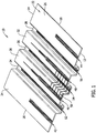
- Figures 1-3 are representations of a first example of a tool 10 used in practicing a method of directing a flow of liquid resin through a preform.
- the tool 10 has a general rectangular configuration defined by first 12 and second 14 opposite, parallel edges and third 16 and fourth 18 opposite, parallel edges.
- the four edges 12, 14, 16, 18 of the tool 10 extend around and form a periphery of a top surface or a tool surface 22 of the tool.
- the tool surface 22 of the tool 10 has four planar sections 24, 26, 28, 32 and three trough sections 34, 36, 38.
- the tool surface 22 could have various other, equivalent configurations, depending on the configuration of the composite part to be formed by the tool 10.
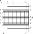
- a first plurality of grooves 42 and a second plurality of grooves 44 are formed in the respective planar sections 24, 26 at the opposite sides of the tool surface 22.
- the first plurality of grooves 42 and the second plurality of grooves 44 are all straight, parallel grooves that extend across the respective planar sections 24, 26 of the tool surface 22 from the first edge 12 of the tool 10 toward the second edge 14, but stop about halfway across the tool surface 22.
- the first plurality of grooves 42 and the second plurality of grooves 44 are machined into the tool surface 22 or formed in the tool surface 22 by an other equivalent means.
- the first plurality of grooves 42 and the second plurality of grooves 44 are arranged in basically the same configuration or pattern, and have substantially the same lengths.
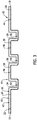
- the first plurality of grooves 42 and the second plurality of grooves 44 have substantially the same cross-section configurations.
- the cross-section configurations are represented as having a v-shape, the grooves could have other equivalent cross-section configurations such as rounded, square, etc.
- a third plurality of grooves 46 and a fourth plurality of grooves 48 are formed in the respective planar sections 28, 32 in the middle of the tool surface 22.
- the third plurality of grooves 46 and the fourth plurality of grooves 48 are straight, parallel grooves that extend from the first edge 12 of the tool 10 toward the opposite second edge 14 of the tool, but stop short of the second edge 14.
- the third plurality of grooves 46 and the fourth plurality of grooves 48 are also machined into the tool surface 22 or formed in the tool surface 22 by other equivalent means.
- the third plurality of grooves 46 and the fourth plurality of grooves 48 are arranged in basically the same configurations or patterns, and include grooves having different lengths.
- the configuration or pattern of the third plurality of grooves 46 and the fourth plurality of grooves 48 is different from the configuration or pattern of the first plurality of grooves 42 and the second plurality of grooves 44.
- the third plurality of grooves 46 and the fourth plurality of grooves 48 have substantially the same cross-section configurations.
- a fifth plurality of grooves 52, a sixth plurality of grooves 54 and a seventh plurality of grooves 56 are also formed in the top surface 22.
- the fifth plurality of grooves 52, the sixth plurality of grooves 54 and the seventh plurality of grooves 58 extend across the tool surface 22 of the tool 10 at the bottoms of the three trough sections 34, 36, 38, respectively.
- the fifth plurality of grooves 52, the sixth plurality of grooves 54 and the seventh plurality of grooves 56 are all straight, parallel grooves that extend from the first edge 12 of the tool 10 toward the opposite second edge 14 of the tool, but end short of the second edge. Again, the grooves are machined into the tool surface 22 or formed in the tool surface 22 by other equivalent means.
- the grooves of the fifth plurality of grooves 52, the sixth plurality of grooves 54 and the seventh plurality of grooves 56 are all formed with the same lengths. However, the lengths of the grooves of the fifth plurality of grooves 52, the sixth plurality of grooves 54 and the seventh plurality of grooves 56 are all different from the lengths of the first plurality of grooves 42, the second plurality of grooves 44, the third plurality of grooves 46 and the fourth plurality of grooves 48.
- the pattern or configuration of the grooves of the fifth plurality of grooves 52, the sixth plurality of grooves 54 and the seventh plurality of grooves 56 are the same, but are different from the configurations or patterns of the first plurality of grooves 42, the second plurality of grooves 44, the third plurality of grooves 46 and the fourth plurality of grooves 48.
- the fifth plurality of grooves 52, the sixth plurality of grooves 54 and the seventh plurality of grooves 56 have substantially the same cross-section configuration.
- An eighth plurality of grooves 58 is also formed in the tool surface 22. As represented in Figures 1 and 2 , the eighth plurality of grooves 58 is formed in the tool surface 22 perpendicular to the first, second, third, fourth, fifth, sixth and seventh pluralities of grooves.
- the eighth plurality of grooves 58 are all straight, parallel grooves that extend across some of the third 46 and fourth 48 pluralities of grooves on the respective third 28 and fourth 32 planar sections of the tool surface 22, and extend across the sixth plurality of grooves 54 in the trough section 36 at the center of the tool surface 22.
- the eighth plurality of grooves 58 communicate some of the third 46 and fourth 48 pluralities of grooves with the sixth plurality of grooves 54 at the center of the tool surface 22.
- the grooves of the eighth plurality of grooves 58 are spaced further from each other than the first, second, third, fourth, fifth, sixth and seventh pluralities of grooves. Additionally, the grooves of the eighth plurality of grooves 58 are wider than the grooves of the first, second, third, fourth, fifth, sixth and seventh pluralities of grooves, and therefore have a larger cross-section configuration.
- Figure 4 is a representation of the method of using the tool 10 in manufacturing a fiber reinforced composite part in resin infusion and resin transfer molding.
- a dry fiber composite preform 62 is positioned on the tool surface 22 of the tool 10.
- the preform 62 is positioned over the pluralities of grooves 42, 44, 46, 48, 52, 54, 56, 58 formed in the tool surface 22.
- the preform 62 has a configuration that closely follows the configuration of the tool surface 22.
- the preform 62 could have other configurations different from the configuration of the tool surface 22.
- a fluid impervious sheet 64, or second tool or vacuum bag 64 is then positioned on the tool surface 22.
- the vacuum bag 64 covers over the preform 62.
- the perimeter of the vacuum bag 64 is sealed to the tool surface 22 over the preform 62 and around the preform. This forms a sealed volume 66 between the vacuum bag 64 and the tool surface 22 that is occupied only by the preform 62. If resin distribution media is used elsewhere in the sealed volume 66, it is not present on the grooves 42, 44, 46, 48, 52, 54, 56, 58 or between the grooves and the preform 62.
- the grooves 42, 44, 46, 48, 52, 54, 56, 58 enable the use of resin distribution media to be significantly reduced. This is represented in Figure 3 .
- a pressure differential 68 is applied to the sealed volume 66.
- the pressure differential 68 is represented schematically in Figure 4 .
- the pressure differential 68 can be introduced to the tool surface 22 and applied into the sealed volume 66 in any conventional manner.
- the pressure differential 68 applied to the sealed volume 66 between the vacuum bag 64 and the tool surface 22 draws the vacuum bag 64 down onto the preform 62 and infuses liquid resin into the preform 62.
- a flow of liquid resin 70 is then supplied to the tool surface 22 and into the sealed volume 66.
- the flow of liquid resin 70 is represented schematically in Figure 4 .
- the flow of liquid resin 70 can be supplied to the tool surface 22 in any conventional manner. Although the flow of liquid resin 70 is represented as being supplied to the first edge 12 of the tool surface 22, toward the center of the first edge 12, the flow of liquid resin 70 could be supplied to the tool surface 22 at some other location around the tool surface. For example, the flow of liquid resin 70 could be introduced at one or more edges of the tool surface 22, or at discrete locations between the tool surface 22 and the preform 62.
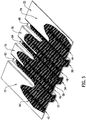
- Figure 5 is a representation of how the flow of liquid resin 70 supplied into the sealed volume 66 is directed across the tool surface 22 and through the perform 62 by the vacuum pressure pulling the flow of liquid resin through the grooves 42, 44, 46, 48, 52, 54, 56, 58 in the tool surface 22.
- the grooves 42, 44, 46, 48, 52, 54, 56 direct the flow of liquid resin 70 to targeted areas or discrete areas 72, 74, 76, 78, 82, 84, 86, respectively, on the tool surface 22.
- a first portion of the flow of liquid resin 70 is directed to the first discrete area 72 on the tool surface 22 through the first group of grooves 42.
- a second portion of the flow of liquid resin 70 is directed to the second discrete area 74 on the tool surface 22 through the second group of grooves 44.
- a third portion of the flow of liquid resin 70 is directed to the third discrete area 76 on the tool surface 22 through the third group of grooves 46.
- a fourth portion of the flow of liquid resin 70 is directed to the fourth discrete area 78 on the tool surface 22 through the fourth group of grooves 48.
- a fifth portion of the flow of liquid resin 70 is directed to a fifth discrete area 82 on the tool surface 22 through the fifth group of grooves 52.
- a sixth portion of the flow of liquid resin 70 is directed to the sixth discrete area 84 on the tool surface 22 through the sixth group of grooves 54.
- a seventh portion of the flow of liquid resin 70 is directed to the seventh discrete area 86 on the tool surface 22 through the seventh group of grooves 56.
- the grooves 42, 44, 46, 48, 52, 54, 56 assist in the distribution of the liquid resin 70 throughout the preform 62.
- Different volumes of the flow of liquid resin 70 can be supplied to the discrete areas 72, 74, 76, 78, 82, 84, 86 through grooves having different cross-section dimensions, different length dimensions and different configurations or patterns.
- the liquid resin is then cured in the preform, forming the fiber reinforced composite part.
- the composite part is then removed from the tool surface 22. Any cured resin remaining in the grooves 42, 44, 46, 48, 52, 54, 56, 58 in the tool surface 22 can then be removed from the grooves.
- the patterns or configurations of the plurality of grooves 42, 44, 46, 48, 52, 54, 56, 58 represented in Figures 1-5 are not the only patterns or configurations of grooves that could be used in practicing the method of delivering and distributing liquid resin supplied to a tool surface throughout a dry fiber composite layup positioned on the tool surface in resin infusion and resin transfer molding.
- Figures 6-9 represent another example of liquid resin distribution grooves formed in a tool surface of a tool.
- the grooves of Figures 6-9 are formed in the same manner as those of Figures 1-3 .
- the tool 90 of Figures 6-9 also has a general rectangular configuration similar to the tool 10 of Figures 1-5 . However, the tool 90 could have other configurations.
- the tool 90 has a tool surface 92 with four planar sections 94, 96, 98, 102 and three trough sections 104, 106, 108.
- the tool surface 92 could have other configurations depending on the fiber reinforced composite part to be produced by the tool.
- the plurality of grooves formed in the tool surface 92 of Figures 6-9 include grooves 112, 114 formed in the respective outer planar sections 94, 96 of the tool surface 92. These grooves 112, 114 have substantially the same configurations or patterns with the grooves extending parallel and straight across the tool surface 92, but not completely across the tool surface.
- the pluralities of grooves also include pluralities of grooves 116, 118, 122 that extend across the respective trough sections 104, 106, 108 of the tool surface 92. These pluralities of grooves 116, 118, 122 also have the same configurations or patterns, with the grooves being parallel and straight and extending across almost the entire lengths of the trough sections 104, 106, 108.
- a further plurality of grooves 124 extend perpendicular to the other pluralities of grooves 112, 114, 116, 118, 122 and intersect with and communicate with grooves of the three pluralities of grooves 116, 118, 122 in the trough sections 104, 106, 108.
- the representations of the grooves in Figures 6-8 show that the grooves in the tool surface can have various different configurations that best suit the grooves for directing and delivering liquid resin across the tool surface to discrete areas on the tool surface in basically the same manner as described earlier with reference to Figures 1-5 .
- the pattern of the grooves eliminates the need for resin distribution media on the tool surface.
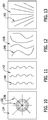
- Figures 10-13 represent other possible configurations or patterns of grooves formed into a tool surface of a tool to assist in the distribution and delivery of liquid resin across the tool surface and into a preform on the tool surface without the need for resin distribution media.
- Figure 10 represents a first pattern of grooves 132 in the tool surface 134 and a second pattern of grooves 136 in the tool surface.
- the first configuration or pattern of grooves 132 is comprised of circular, concentric grooves and the second configuration or pattern of grooves 136 is comprised of straight grooves that radiate outwardly from a center of the tool surface 134.
- Figure 11 represents a tool surface 142 having pluralities of grooves 144 formed in the tool surface.
- the pattern or configuration of the plurality of grooves 144 represented in Figure 11 includes grooves that extend across the tool surface 142 with there being multiple tight bends or curves in the grooves 144.
- the plurality of grooves 146 in the tool surface 148 of the tool represented in Figure 12 includes a plurality of grooves with large bends or curves that extend across the tool surface.
- the plurality of grooves 152 in the tool surface 154 of the tool of Figure 13 includes grooves 152 that extend straight across the tool surface 154 and spread across the tool surface as they extend across the tool surface.
- the pluralities of grooves formed in the tool surface can have a variety of different configurations or patterns, different lengths and different dimensions that best suit the grooves for delivering and distributing liquid resin across the tool surface and into a preform positioned on the tool surface without the need for resin distribution media.
Landscapes
- Chemical & Material Sciences (AREA)
- Engineering & Computer Science (AREA)
- Composite Materials (AREA)
- Mechanical Engineering (AREA)
- Casting Or Compression Moulding Of Plastics Or The Like (AREA)
- Moulds For Moulding Plastics Or The Like (AREA)
Abstract
Description
- This disclosure is directed to a tool and its method of use, where a plurality of grooves are cut or formed into the tool surface of the tool. The grooves have different cross-section dimensions, different lengths, different configurations and/or different patterns that function as tool surface resin distribution grooves. The grooves distribute and deliver resin supplied to the tool surface throughout a dry fiber composite layup positioned on the tool surface in resin infusion and resin transfer molding. The grooves are formed in the tool surface extending to discrete areas on the tool surface to direct a flow of liquid resin to the discrete areas and infuse the dry fiber composite layup with the liquid resin at those discrete areas of the tool surface.
- In tool or tool surface resin distribution molding in forming fiber reinforced composite parts, dry fiber composite is laid up on the tool surface forming a preform on the tool surface.
- In liquid molding, a fluid impervious sheet, a second tool (with or without grooves) or vacuum bag is then secured to the tool surface over the preform. The edges of the vacuum bag, or tool are sealed to the tool surface to form a sealed volume on the tool surface containing the preform.
- A supply of liquid resin is then introduced into the sealed volume to wet the preform on the tool surface. A pressure differential is applied to the sealed volume, to draw the liquid resin across the preform and to infuse the liquid resin into the preform. Vacuum may be applied to create the pressure differential. The liquid resin is then cured, forming the fiber reinforced composite part.
- To assist in the distribution of the liquid resin throughout the preform, resin distribution media are often positioned in the sealed volume between the vacuum bag and the tool surface. The resin distribution media is typically positioned on top of the preform and/or beneath the preform. The resin distribution media form pathways through which the liquid resin can flow when infusing the preform with the liquid resin. The resin distribution media thereby distribute the liquid resin entirely over the preform.
- However, after curing of the fiber reinforced composite part, the resin distribution media must be removed from the part and discarded. Both the resin distribution media and any additional resin it contains are discarded. Thus, the use of resin distribution media to distribute liquid resin throughout the preform results in wasted resin.
- Additionally, as the liquid distribution media is positioned on top of the preform, the fiber composite layup forming the preform can be altered. This could result in a fiber reinforced composite part not having the structural strength intended.
- Still further, the use of resin distribution media on the preform to distribute liquid resin throughout the preform could result in the resin distribution media negatively affecting the surface of the fiber reinforced composite part being molded.
- The apparatus and its method of use of this disclosure provides targeted liquid resin distribution throughout an assembled dry fiber composite preform in resin infusion and resin transfer molding by using a discrete network of infusion grooves formed in a tool surface of a tool. The grooves are preferably formed in the tool surface in predetermined patterns or configurations that extend from the resin source to discrete areas on the tool surface that would typically be difficult to reach by the liquid resin distributed over the tool surface.
- The tool is used to supply resin into a dry fiber composite layup, or a preform using a pressure differential. In the method of using the tool, the preform is first positioned on a tool surface of the tool into which a plurality of grooves have been formed or machined. The plurality of grooves preferably include several different patterns or configurations of grooves and different dimensions of grooves on the tool surface. The different patterns and different dimensions of the grooves preferably are determined to optimize the delivery and distribution of liquid resin throughout the preform positioned on the tool surface. The preform preferably is positioned on the tool surface covering over the plurality of grooves.
- A fluid impervious sheet or tool or a vacuum bag preferably is then positioned on the tool surface. The vacuum bag preferably covers over the preform.
- The fluid impervious sheet, tool or vacuum bag preferably is then sealed to the tool surface over the preform and around the preform. This forms a sealed volume around the preform.
- A flow of liquid resin preferably is then supplied into the sealed volume. The flow of liquid resin may be introduced at one end of the tool surface, along one or more edges of the tool surface, or at discrete locations between the tool surface and the preform.
- A pressure differential preferably is also applied to the sealed volume to draw the liquid resin across the tool surface and through the preform.
- The flow of liquid resin supplied into the sealed volume preferably is directed through the preform by the pressure differential pulling the flow of resin through the grooves in the tool surface. The grooves in the tool surface preferably direct the flow of liquid resin to targeted areas on the tool surface and assist in the distribution of the liquid resin throughout the preform.
- The liquid resin preferably is then cured in the preform, forming the fiber reinforced composite part.
- The composite part preferably is then removed from the tool surface of the tool. Any resin remaining in the grooves in the surface of the tool preferably is then cleaned from the grooves.
- The features, functions and advantages that have been discussed can be achieved independently in various embodiments or may be combined in yet other embodiments, further details of which can be seen with reference to the following description and drawings.
- Further, the disclosure comprises embodiments according to the following clauses:
- Clause 1. A method of directing a flow of liquid resin through a preform, the method comprising: positioning a preform (62) on a tool surface (22) with the preform (62) covering over grooves (42, 44, 46, 48, 52, 54, 56, 58) in the tool surface (22); positioning at least one of a fluid impervious sheet, a second tool and a vacuum bag (64) on the tool surface over the preform (62); sealing the at least one of the fluid impervious sheet, the second tool and the vacuum bag (64) on the tool surface (22) over the preform (62) forming a sealed volume (66) between the fluid impervious sheet (64) and the tool surface (22); supplying a pressure differential (68) into the sealed volume (66); supplying a flow of liquid resin (70) into the sealed volume (66); and, directing the flow of liquid resin (70) supplied into the sealed volume (66) through the preform (62) by the pressure differential (68) pulling the flow of liquid resin (70) through the grooves (42, 44, 46, 48, 52, 54, 56, 58) in the tool surface (22) with the grooves (42, 44, 46, 48, 52, 54, 56, 58) in the tool surface (22) directing the flow of liquid resin (70) into discrete areas (72, 74, 76, 78, 82, 84, 86) on the tool surface (22).
- Clause 2. The method of clause 1, further comprising: directing different volumes of the flow of liquid resin (70) supplied into the sealed volume (66) to the discrete areas (72, 74, 76, 78, 82, 84, 86) on the tool surface (22) through grooves (42, 44, 46, 48, 52, 54, 56, 58) in the tool surface (22) having different cross-section dimensions.
- Clause 3. The method of clause 1 or2, further comprising: directing different volumes of the flow of liquid resin (70) supplied into the sealed volume (66) to the discrete areas (72, 74, 76, 78, 82, 84, 86) on the tool surface (22) through grooves (42, 44, 46, 48, 52, 54, 56, 58) in the tool surface (22) having different length dimensions.
- Clause 4. The method of any one of clauses 1-3, further comprising: directing different volumes of the flow of liquid resin (70) supplied into the sealed volume (66) to the discrete areas (72, 74, 76, 78, 82, 84, 86) on the tool surface (22) through grooves (42, 44, 46, 48, 52, 54, 56, 58) in the tool surface (22) having different configurations.
- Clause 5. The method of any one of clauses 1-4, further comprising: directing a first portion of the flow of liquid resin (70) supplied into the sealed volume (66) to a first area (72) on the tool surface (22) through a first group of grooves (42) in the tool surface (22); and, directing a second portion of the flow of liquid resin (70) suppled into the sealed volume (66) to a second area (74) on the tool surface (22) that is separate and discrete from the first area (72) on the tool surface (22) through a second group of grooves (44) in the tool surface (22), the second group of grooves (44) being separate from the first group of grooves (42).
- Clause 6. The method of any one of clauses 1-5, further comprising: directing a first portion of the flow of liquid resin (70) supplied into the sealed volume (66) to a first area (72) on the tool surface (22) through a first pattern of grooves (42) in the tool surface (22); and, directing a second portion of the flow of liquid resin (70) supplied into the sealed volume (66) to a second area (82) on the tool surface (22) that is separate and discrete from the first area (72) on the tool surface (22) through a second pattern of grooves (52) in the tool surface (22), the second pattern of grooves (52) being different from the first pattern of grooves (42).
- Clause 7. The method of any one of clauses 5to 6, further comprising: directing a third portion of the flow of liquid resin (70) supplied into the sealed volume (66) to a third area (76) on the tool surface (22) that is separate and discrete from the first area (72) on the tool surface (22) and is separate and discrete from the second area (74) on the tool surface (22) through a third group of grooves (46) in the tool surface (22), the third group of grooves (46) being separate from the first group of grooves (42) and the second group of grooves (44).
-
Clause 8. The method of any one of clauses 1-7, further comprising: curing the liquid resin (70) in the preform (62) and thereby forming a composite part; and, removing the composite part from the tool surface (22). - Clause 9. The method of
clause 8, further comprising: removing any cured resin from the grooves (42, 44, 46, 48, 52, 54, 56, 58) in the tool surface (22). -
Clause 10. A method of infusing liquid resin into a preform, the method comprising: using a tool (10) having a tool surface (22) with a plurality of grooves (42, 44, 46, 48, 52, 54, 56, 58) in the tool surface (22); positioning a preform (62) on the tool surface (22) over the plurality of grooves (42, 44, 46, 48, 52, 54, 56, 58); securing a fluid impervious sheet (64) on the tool surface (22) over the preform (62); supplying a pressure differential (68) to the tool surface (22); supplying a flow of liquid resin (70) onto the tool surface (22); and, infusing the flow of liquid resin (70) supplied onto the tool surface (22) into the preform (62) by the vacuum pressure (68) drawing the flow of the liquid resin (70) across the tool surface (22) and through the grooves (42, 44, 46, 48, 52, 54, 56, 58) in the tool surface (22) with the grooves (42, 44, 46, 48, 52, 54, 56, 58) in the tool surface (22) directing the flow of liquid resin (70) to discrete areas (72, 74, 76, 78, 82, 84, 86) on the tool surface (22) and infusing the flow of liquid resin (70) into the preform (62) on the tool surface (22) at the discrete areas (72, 74, 76, 78, 82, 84, 86) of the tool surface (22). - Clause 11. The method of
clause 10, further comprising: directing different volumes of the flow of liquid resin (70) supplied onto the tool surface (22) across the tool surface (22) to the discrete areas (72, 74, 76, 78, 82, 84, 86) on the tool surface (22) through grooves (42, 44, 46, 48, 52, 54, 56, 58) in the tool surface (22) that extend to the discrete areas (72, 74, 76, 78, 82, 84, 86) and have different cross-section dimensions. -
Clause 12. The method ofclause 10 or11, further comprising: directing different volumes of the flow of liquid resin (70) supplied onto the tool surface (22) across the tool surface (22) to the discrete areas (72, 74, 76, 78, 82, 84, 86) on the tool surface (22) through grooves (42, 44, 46, 48, 52, 54, 56, 58) in the tool surface (22) that extend to the discrete areas (72, 74, 76, 78, 82, 84, 86) and have different length dimensions. - Clause 13. The method of any one of clauses 10-12, further comprising: directing different volumes of the flow of liquid resin (70) supplied onto the tool surface (22) across the tool surface (22) to discrete areas (72, 74, 76, 78, 82, 84, 86) on the tool surface (22) through grooves (42, 44, 46, 48, 52, 54, 56, 58) in the tool surface (22) that extend to the discrete areas (72, 74, 76, 78, 82, 84, 86) and have different configurations.
-
Clause 14. The method any one of clauses 10-13, further comprising: directing a first portion of the flow of liquid resin (70) supplied onto the tool surface (22) across the tool surface (22) to a first area (72) on the tool surface (22) through a first group of grooves (42) in the tool surface (22) that extend to the first area (72); and, directing a second portion of the flow of liquid resin (70) supplied onto the tool surface (22) across the tool surface (22) to a second area (74) on the tool surface (22) that is separate and discrete from the first area (72) on the tool surface (22) through a second group of grooves (44) in the tool surface (22) that extend to the second area (74), the second group of grooves (44) being separate from the first group of grooves (42). - Clause 15. The method of any one of clauses 10-14, further comprising: directing a first portion of the flow of liquid resin (70) supplied onto the tool surface (22) across the tool surface (22) to a first area (72) on the tool surface (22) through a first pattern of grooves (42) in the tool surface (22) that extend across the tool surface (22) to the first area (72) on the tool surface (22); and, directing a second portion of the flow of liquid resin (70) supplied onto the tool surface (22) across the tool surface (22) to a second area (82) on the tool surface (22) that is separate and discrete from the first area (72) on the tool surface (22) through a second pattern of grooves (52) in the tool surface (22) that extend across the tool surface (22) to the second area (82) on the tool surface (22).
-
Clause 16. The method of clause 15, further comprising: the first pattern of grooves (42) in the tool surface (22) being different from the second pattern of grooves (52) in the tool surface (22). - Clause 17. The method of any one of clauses 15-16, further comprising: directing a third portion of the flow of liquid resin (70) supplied onto the tool surface (22) across the tool surface (22) to a third area (76) on the tool surface (22) that is separate and discrete from the first area (72) on the tool surface (22) and separate and discrete from the second area (82) on the tool surface (22) through a third group of grooves (46) in the tool surface (22) that extend across the tool surface (22) to the third area (76) on the tool surface (22).
-
Clause 18. The method of any one of clauses 10-17, further comprising: the plurality of grooves (42, 44, 46, 48, 52, 54, 56, 58) in the tool surface (22) eliminating a need for a resin distribution media on the tool surface (22). - Clause 19. A tool for directing a flow of liquid resin through a preform, the tool comprising: a tool surface (22) on the tool (10); a plurality of grooves (42, 44, 46, 48, 52, 54, 56, 58) in the tool surface (22); a preform (62) on the tool surface (22) over the plurality of grooves (42, 44, 46, 48, 52, 54, 56, 58); a fluid impervious sheet (64) sealed to the tool surface (22) around the preform (62) forming a sealed volume (66) between the fluid impervious sheet (64) and the tool surface (22); a supply of liquid resin (70) communicating with the sealed volume (66); a supply of a pressure differential (68) communicating with the sealed volume (66); and, the supply of the pressure differential (68) being operable when supplied into the sealed volume (66) to draw a flow of liquid resin (70) into the sealed volume (66) from the supply of liquid resin (70) and through the grooves (42, 44, 46, 48, 52, 54, 56, 58) in the tool surface (22) where the grooves (42, 44, 46, 48, 52, 54, 56, 58) direct the flow of liquid resin (70) to discrete areas (72, 74, 76, 78, 82, 84, 86) on the tool surface (22) and through the preform (62).
- Clause 20. The tool of clause 19, further comprising:
the sealed volume (66) being occupied by the preform (62) with there being no resin distribution media in the sealed volume (66) between the plurality of grooves (42, 44, 46, 48, 52, 54, 56, 58) and the preform (62). -
-
Figure 1 is a representation of an isometric view of a first example of the tool of this disclosure. -
Figure 2 is a representation of a plan view of the tool ofFigure 1 . -
Figure 3 is a representation of a cross-section view of the tool ofFigure 2 . -
Figure 4 is a representation of an isometric view of the tool ofFigure 1 with a dry fiber composite preform and a vacuum bag in preparing the tool ofFigure 1 for infusing liquid resin through the preform using the pressure differential. -
Figure 5 is a representation of an isometric view of liquid resin being drawn across the tool surface of the tool ofFigure 1 using the pressure differential. -
Figure 6 is a representation of an isometric view of a second example of the tool of this disclosure. -
Figure 7 is a representation of a plan view of the tool ofFigure 6 . -
Figure 8 is a representation of a cross-section view of the tool along the line 8-8 ofFigure 7 . -
Figure 9 is a representation of liquid resin being drawn across the tool surface of the tool ofFigure 6 using the pressure differential. -
Figures 10-13 are representations of plan views of tools having different patterns or configurations of grooves formed in their tool surfaces. -
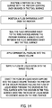
Figure 14 is a flow chart of a method of this disclosure. -
Figures 1-3 are representations of a first example of atool 10 used in practicing a method of directing a flow of liquid resin through a preform. As represented inFigures 1-3 , thetool 10 has a general rectangular configuration defined by first 12 and second 14 opposite, parallel edges and third 16 and fourth 18 opposite, parallel edges. Although thetool 10 is represented as having a rectangular configuration inFigures 1-3 , the tool could have other equivalent configurations. The four edges 12, 14, 16, 18 of thetool 10 extend around and form a periphery of a top surface or atool surface 22 of the tool. As represented inFigures 1-3 , thetool surface 22 of thetool 10 has fourplanar sections trough sections tool surface 22 could have various other, equivalent configurations, depending on the configuration of the composite part to be formed by thetool 10. - A first plurality of
grooves 42 and a second plurality ofgrooves 44 are formed in the respectiveplanar sections tool surface 22. The first plurality ofgrooves 42 and the second plurality ofgrooves 44 are all straight, parallel grooves that extend across the respectiveplanar sections tool surface 22 from thefirst edge 12 of thetool 10 toward thesecond edge 14, but stop about halfway across thetool surface 22. The first plurality ofgrooves 42 and the second plurality ofgrooves 44 are machined into thetool surface 22 or formed in thetool surface 22 by an other equivalent means. The first plurality ofgrooves 42 and the second plurality ofgrooves 44 are arranged in basically the same configuration or pattern, and have substantially the same lengths. As represented inFigure 3 , the first plurality ofgrooves 42 and the second plurality ofgrooves 44 have substantially the same cross-section configurations. Although the cross-section configurations are represented as having a v-shape, the grooves could have other equivalent cross-section configurations such as rounded, square, etc. - A third plurality of
grooves 46 and a fourth plurality ofgrooves 48 are formed in the respectiveplanar sections tool surface 22. The third plurality ofgrooves 46 and the fourth plurality ofgrooves 48 are straight, parallel grooves that extend from thefirst edge 12 of thetool 10 toward the oppositesecond edge 14 of the tool, but stop short of thesecond edge 14. The third plurality ofgrooves 46 and the fourth plurality ofgrooves 48 are also machined into thetool surface 22 or formed in thetool surface 22 by other equivalent means. The third plurality ofgrooves 46 and the fourth plurality ofgrooves 48 are arranged in basically the same configurations or patterns, and include grooves having different lengths. Thus, the configuration or pattern of the third plurality ofgrooves 46 and the fourth plurality ofgrooves 48 is different from the configuration or pattern of the first plurality ofgrooves 42 and the second plurality ofgrooves 44. As represented inFigure 3 , the third plurality ofgrooves 46 and the fourth plurality ofgrooves 48 have substantially the same cross-section configurations. - A fifth plurality of
grooves 52, a sixth plurality ofgrooves 54 and a seventh plurality ofgrooves 56 are also formed in thetop surface 22. The fifth plurality ofgrooves 52, the sixth plurality ofgrooves 54 and the seventh plurality ofgrooves 58 extend across thetool surface 22 of thetool 10 at the bottoms of the threetrough sections grooves 52, the sixth plurality ofgrooves 54 and the seventh plurality ofgrooves 56 are all straight, parallel grooves that extend from thefirst edge 12 of thetool 10 toward the oppositesecond edge 14 of the tool, but end short of the second edge. Again, the grooves are machined into thetool surface 22 or formed in thetool surface 22 by other equivalent means. The grooves of the fifth plurality ofgrooves 52, the sixth plurality ofgrooves 54 and the seventh plurality ofgrooves 56 are all formed with the same lengths. However, the lengths of the grooves of the fifth plurality ofgrooves 52, the sixth plurality ofgrooves 54 and the seventh plurality ofgrooves 56 are all different from the lengths of the first plurality ofgrooves 42, the second plurality ofgrooves 44, the third plurality ofgrooves 46 and the fourth plurality ofgrooves 48. Thus, the pattern or configuration of the grooves of the fifth plurality ofgrooves 52, the sixth plurality ofgrooves 54 and the seventh plurality ofgrooves 56 are the same, but are different from the configurations or patterns of the first plurality ofgrooves 42, the second plurality ofgrooves 44, the third plurality ofgrooves 46 and the fourth plurality ofgrooves 48. As represented inFigure 3 , the fifth plurality ofgrooves 52, the sixth plurality ofgrooves 54 and the seventh plurality ofgrooves 56 have substantially the same cross-section configuration. - An eighth plurality of
grooves 58 is also formed in thetool surface 22. As represented inFigures 1 and2 , the eighth plurality ofgrooves 58 is formed in thetool surface 22 perpendicular to the first, second, third, fourth, fifth, sixth and seventh pluralities of grooves. The eighth plurality ofgrooves 58 are all straight, parallel grooves that extend across some of the third 46 and fourth 48 pluralities of grooves on the respective third 28 and fourth 32 planar sections of thetool surface 22, and extend across the sixth plurality ofgrooves 54 in thetrough section 36 at the center of thetool surface 22. Thus, the eighth plurality ofgrooves 58 communicate some of the third 46 and fourth 48 pluralities of grooves with the sixth plurality ofgrooves 54 at the center of thetool surface 22. The grooves of the eighth plurality ofgrooves 58 are spaced further from each other than the first, second, third, fourth, fifth, sixth and seventh pluralities of grooves. Additionally, the grooves of the eighth plurality ofgrooves 58 are wider than the grooves of the first, second, third, fourth, fifth, sixth and seventh pluralities of grooves, and therefore have a larger cross-section configuration. -
Figure 4 is a representation of the method of using thetool 10 in manufacturing a fiber reinforced composite part in resin infusion and resin transfer molding. In the method represented inFigure 4 , a dry fibercomposite preform 62 is positioned on thetool surface 22 of thetool 10. Thepreform 62 is positioned over the pluralities ofgrooves tool surface 22. In the example represented inFigure 4 , thepreform 62 has a configuration that closely follows the configuration of thetool surface 22. However, thepreform 62 could have other configurations different from the configuration of thetool surface 22. - A fluid
impervious sheet 64, or second tool orvacuum bag 64 is then positioned on thetool surface 22. Thevacuum bag 64 covers over thepreform 62. The perimeter of thevacuum bag 64 is sealed to thetool surface 22 over thepreform 62 and around the preform. This forms a sealed volume 66 between thevacuum bag 64 and thetool surface 22 that is occupied only by thepreform 62. If resin distribution media is used elsewhere in the sealed volume 66, it is not present on thegrooves preform 62. Thegrooves Figure 3 . - A pressure differential 68 is applied to the sealed volume 66. The pressure differential 68 is represented schematically in
Figure 4 . The pressure differential 68 can be introduced to thetool surface 22 and applied into the sealed volume 66 in any conventional manner. The pressure differential 68 applied to the sealed volume 66 between thevacuum bag 64 and thetool surface 22 draws thevacuum bag 64 down onto thepreform 62 and infuses liquid resin into thepreform 62. - A flow of
liquid resin 70 is then supplied to thetool surface 22 and into the sealed volume 66. The flow ofliquid resin 70 is represented schematically inFigure 4 . The flow ofliquid resin 70 can be supplied to thetool surface 22 in any conventional manner. Although the flow ofliquid resin 70 is represented as being supplied to thefirst edge 12 of thetool surface 22, toward the center of thefirst edge 12, the flow ofliquid resin 70 could be supplied to thetool surface 22 at some other location around the tool surface. For example, the flow ofliquid resin 70 could be introduced at one or more edges of thetool surface 22, or at discrete locations between thetool surface 22 and thepreform 62. -
Figure 5 is a representation of how the flow ofliquid resin 70 supplied into the sealed volume 66 is directed across thetool surface 22 and through theperform 62 by the vacuum pressure pulling the flow of liquid resin through thegrooves tool surface 22. Thegrooves liquid resin 70 to targeted areas ordiscrete areas tool surface 22. A first portion of the flow ofliquid resin 70 is directed to the firstdiscrete area 72 on thetool surface 22 through the first group ofgrooves 42. A second portion of the flow ofliquid resin 70 is directed to the seconddiscrete area 74 on thetool surface 22 through the second group ofgrooves 44. A third portion of the flow ofliquid resin 70 is directed to the thirddiscrete area 76 on thetool surface 22 through the third group ofgrooves 46. A fourth portion of the flow ofliquid resin 70 is directed to the fourthdiscrete area 78 on thetool surface 22 through the fourth group ofgrooves 48. A fifth portion of the flow ofliquid resin 70 is directed to a fifthdiscrete area 82 on thetool surface 22 through the fifth group ofgrooves 52. A sixth portion of the flow ofliquid resin 70 is directed to the sixthdiscrete area 84 on thetool surface 22 through the sixth group ofgrooves 54. A seventh portion of the flow ofliquid resin 70 is directed to the seventhdiscrete area 86 on thetool surface 22 through the seventh group ofgrooves 56. In this manner, thegrooves liquid resin 70 throughout thepreform 62. - Different volumes of the flow of
liquid resin 70 can be supplied to thediscrete areas - The liquid resin is then cured in the preform, forming the fiber reinforced composite part.
- The composite part is then removed from the
tool surface 22. Any cured resin remaining in thegrooves tool surface 22 can then be removed from the grooves. - The patterns or configurations of the plurality of
grooves Figures 1-5 are not the only patterns or configurations of grooves that could be used in practicing the method of delivering and distributing liquid resin supplied to a tool surface throughout a dry fiber composite layup positioned on the tool surface in resin infusion and resin transfer molding.Figures 6-9 represent another example of liquid resin distribution grooves formed in a tool surface of a tool. The grooves ofFigures 6-9 are formed in the same manner as those ofFigures 1-3 . Thetool 90 ofFigures 6-9 also has a general rectangular configuration similar to thetool 10 ofFigures 1-5 . However, thetool 90 could have other configurations. Thetool 90 has atool surface 92 with fourplanar sections trough sections tool surface 92 could have other configurations depending on the fiber reinforced composite part to be produced by the tool. The plurality of grooves formed in thetool surface 92 ofFigures 6-9 includegrooves planar sections tool surface 92. Thesegrooves tool surface 92, but not completely across the tool surface. - The pluralities of grooves also include pluralities of
grooves respective trough sections tool surface 92. These pluralities ofgrooves trough sections - A further plurality of
grooves 124 extend perpendicular to the other pluralities ofgrooves grooves trough sections - The representations of the grooves in
Figures 6-8 show that the grooves in the tool surface can have various different configurations that best suit the grooves for directing and delivering liquid resin across the tool surface to discrete areas on the tool surface in basically the same manner as described earlier with reference toFigures 1-5 . The pattern of the grooves eliminates the need for resin distribution media on the tool surface. -
Figures 10-13 represent other possible configurations or patterns of grooves formed into a tool surface of a tool to assist in the distribution and delivery of liquid resin across the tool surface and into a preform on the tool surface without the need for resin distribution media. -
Figure 10 represents a first pattern ofgrooves 132 in thetool surface 134 and a second pattern ofgrooves 136 in the tool surface. As represented inFigure 10 , the first configuration or pattern ofgrooves 132 is comprised of circular, concentric grooves and the second configuration or pattern ofgrooves 136 is comprised of straight grooves that radiate outwardly from a center of thetool surface 134. -
Figure 11 represents atool surface 142 having pluralities ofgrooves 144 formed in the tool surface. The pattern or configuration of the plurality ofgrooves 144 represented inFigure 11 includes grooves that extend across thetool surface 142 with there being multiple tight bends or curves in thegrooves 144. - The plurality of
grooves 146 in thetool surface 148 of the tool represented inFigure 12 includes a plurality of grooves with large bends or curves that extend across the tool surface. - The plurality of
grooves 152 in thetool surface 154 of the tool ofFigure 13 includesgrooves 152 that extend straight across thetool surface 154 and spread across the tool surface as they extend across the tool surface. - Thus, as represented in the drawing figures, the pluralities of grooves formed in the tool surface can have a variety of different configurations or patterns, different lengths and different dimensions that best suit the grooves for delivering and distributing liquid resin across the tool surface and into a preform positioned on the tool surface without the need for resin distribution media.
- As various modifications could be made in the constructions of the tools and their methods of operation herein described and illustrated without departing from the scope of the invention, it is intended that all matter contained in the foregoing description or shown in the accompanying drawings shall be interpreted as illustrative rather than limiting. Thus, the breadth and scope of the present disclosure should not be limited by any of the above described exemplary embodiments, but should be defined only in accordance with the following claims appended hereto and their equivalents.
Claims (11)
- A method of directing a flow of liquid resin through a preform, the method comprising:positioning a preform (62) on a tool surface (22) with the preform (62) covering over grooves (42, 44, 46, 48, 52, 54, 56, 58) in the tool surface (22);positioning at least one of a fluid impervious sheet, a second tool and a vacuum bag (64) on the tool surface over the preform (62);sealing the at least one of the fluid impervious sheet, the second tool and the vacuum bag (64) on the tool surface (22) over the preform (62) forming a sealed volume (66) between the fluid impervious sheet (64) and the tool surface (22);supplying a pressure differential (68) into the sealed volume (66);supplying a flow of liquid resin (70) into the sealed volume (66); and,directing the flow of liquid resin (70) supplied into the sealed volume (66) through the preform (62) by the pressure differential (68) pulling the flow of liquid resin (70) through the grooves (42, 44, 46, 48, 52, 54, 56, 58) in the tool surface (22) with the grooves (42, 44, 46, 48, 52, 54, 56, 58) in the tool surface (22) directing the flow of liquid resin (70) into discrete areas (72, 74, 76, 78, 82, 84, 86) on the tool surface (22).
- The method of claim 1, further comprising:directing different volumes of the flow of liquid resin (70) supplied into the sealed volume (66) to the discrete areas (72, 74, 76, 78, 82, 84, 86) on the tool surface (22) through grooves (42, 44, 46, 48, 52, 54, 56, 58) in the tool surface (22) having different cross-section dimensions.
- The method of any one of claims 1-2, further comprising:directing different volumes of the flow of liquid resin (70) supplied into the sealed volume (66) to the discrete areas (72, 74, 76, 78, 82, 84, 86) on the tool surface (22) through grooves (42, 44, 46, 48, 52, 54, 56, 58) in the tool surface (22) having different length dimensions.
- The method of any one of claims 1-3, further comprising:directing different volumes of the flow of liquid resin (70) supplied into the sealed volume (66) to the discrete areas (72, 74, 76, 78, 82, 84, 86) on the tool surface (22) through grooves (42, 44, 46, 48, 52, 54, 56, 58) in the tool surface (22) having different configurations.
- The method of any one of claims 1-4, further comprising:directing a first portion of the flow of liquid resin (70) supplied into the sealed volume (66) to a first area (72) on the tool surface (22) through a first group of grooves (42) in the tool surface (22); and,directing a second portion of the flow of liquid resin (70) suppled into the sealed volume (66) to a second area (74) on the tool surface (22) that is separate and discrete from the first area (72) on the tool surface (22) through a second group of grooves (44) in the tool surface (22), the second group of grooves (44) being separate from the first group of grooves (42).
- The method of any one of claims 1-5, further comprising:directing a first portion of the flow of liquid resin (70) supplied into the sealed volume (66) to a first area (72) on the tool surface (22) through a first pattern of grooves (42) in the tool surface (22); and,directing a second portion of the flow of liquid resin (70) supplied into the sealed volume (66) to a second area (82) on the tool surface (22) that is separate and discrete from the first area (72) on the tool surface (22) through a second pattern of grooves (52) in the tool surface (22), the second pattern of grooves (52) being different from the first pattern of grooves (42).
- The method of claim 5 or 6, further comprising:directing a third portion of the flow of liquid resin (70) supplied into the sealed volume (66) to a third area (76) on the tool surface (22) that is separate and discrete from the first area (72) on the tool surface (22) and is separate and discrete from the second area (74) on the tool surface (22) through a third group of grooves (46) in the tool surface (22), the third group of grooves (46) being separate from the first group of grooves (42) and the second group of grooves (44).
- The method of any one of claims 1-7, further comprising:curing the liquid resin (70) in the preform (62) and thereby forming a composite part; and,removing the composite part from the tool surface (22).
- The method of claim 8, further comprising:removing any cured resin from the grooves (42, 44, 46, 48, 52, 54, 56, 58) in the tool surface (22).
- A tool for directing a flow of liquid resin through a preform, the tool comprising:a tool surface (22) on the tool (10);a plurality of grooves (42, 44, 46, 48, 52, 54, 56, 58) in the tool surface (22);a preform (62) on the tool surface (22) over the plurality of grooves (42, 44, 46, 48, 52, 54, 56, 58);a fluid impervious sheet (64) sealed to the tool surface (22) around the preform (62) forming a sealed volume (66) between the fluid impervious sheet (64) and the tool surface (22);a supply of liquid resin (70) communicating with the sealed volume (66);a supply of a pressure differential (68) communicating with the sealed volume (66); and,the supply of the pressure differential (68) being operable when supplied into the sealed volume (66) to draw a flow of liquid resin (70) into the sealed volume (66) from the supply of liquid resin (70) and through the grooves (42, 44, 46, 48, 52, 54, 56, 58) in the tool surface (22) where the grooves (42, 44,jmj n 46, 48, 52, 54, 56, 58) direct the flow of liquid resin (70) to discrete areas (72, 74, 76, 78, 82, 84, 86) on the tool surface (22) and through the preform (62).
- The tool of claim 10, further comprising:the sealed volume (66) being occupied by the preform (62) with there being no resin distribution media in the sealed volume (66) between the plurality of grooves (42, 44, 46, 48, 52, 54, 56, 58) and the preform (62).
Applications Claiming Priority (1)
| Application Number | Priority Date | Filing Date | Title |
|---|---|---|---|
| US15/819,862 US10759124B2 (en) | 2017-11-21 | 2017-11-21 | Apparatus and method for manufacturing liquid molded composites using a discrete network of tool surface resin distribution grooves |
Publications (2)
| Publication Number | Publication Date |
|---|---|
| EP3495122A1 true EP3495122A1 (en) | 2019-06-12 |
| EP3495122B1 EP3495122B1 (en) | 2022-09-07 |
Family
ID=64017291
Family Applications (1)
| Application Number | Title | Priority Date | Filing Date |
|---|---|---|---|
| EP18201899.4A Active EP3495122B1 (en) | 2017-11-21 | 2018-10-23 | Apparatus and method for manufacturing molded composites using a discrete network of tool surface resin distribution grooves |
Country Status (3)
| Country | Link |
|---|---|
| US (1) | US10759124B2 (en) |
| EP (1) | EP3495122B1 (en) |
| AU (1) | AU2018236868B2 (en) |
Families Citing this family (2)
| Publication number | Priority date | Publication date | Assignee | Title |
|---|---|---|---|---|
| US12296547B2 (en) | 2023-06-23 | 2025-05-13 | The Boeing Company | Curing tool assemblies, methods, and systems for composite manufacturing |
| CN121989394B (en) * | 2026-04-09 | 2026-07-21 | 清华大学 | Resin infusion mould |
Citations (4)
| Publication number | Priority date | Publication date | Assignee | Title |
|---|---|---|---|---|
| JP2001062932A (en) * | 1999-08-25 | 2001-03-13 | Toray Ind Inc | Fiber reinforced resin structure and method for producing the same |
| JP2004181627A (en) * | 2002-10-09 | 2004-07-02 | Toray Ind Inc | RTM molding method |
| EP1602470A1 (en) * | 2003-03-13 | 2005-12-07 | Toho Tenax Co., Ltd. | Method of resin transfer molding |
| US20080044506A1 (en) * | 2006-08-17 | 2008-02-21 | Airbus Deutschland Gmbh | Tool for the production of fiber composite components |
Family Cites Families (14)
| Publication number | Priority date | Publication date | Assignee | Title |
|---|---|---|---|---|
| US4942013A (en) * | 1989-03-27 | 1990-07-17 | Mcdonnell Douglas Corporation | Vacuum resin impregnation process |
| US6919039B2 (en) * | 1995-03-28 | 2005-07-19 | Eric J. Lang | Channel assisted resin transfer molding |
| US6406659B1 (en) | 1995-03-28 | 2002-06-18 | Eric Lang | Composite molding method and apparatus |
| US5958325A (en) * | 1995-06-07 | 1999-09-28 | Tpi Technology, Inc. | Large composite structures and a method for production of large composite structures incorporating a resin distribution network |
| US6586054B2 (en) * | 2001-04-24 | 2003-07-01 | The United States Of America As Represented By The Secretary Of The Army | Apparatus and method for selectively distributing and controlling a means for impregnation of fibrous articles |
| EP2565019A1 (en) | 2004-02-17 | 2013-03-06 | Toray Industries, Inc. | RTM molding method |
| CA2739477C (en) * | 2008-10-03 | 2016-12-20 | Short Brothers Plc | Fibre reinforced composite structures and method of manufacture |
| US8516284B2 (en) | 2010-11-04 | 2013-08-20 | International Business Machines Corporation | Saving power by placing inactive computing devices in optimized configuration corresponding to a specific constraint |
| JP5693296B2 (en) | 2011-02-28 | 2015-04-01 | 三菱重工業株式会社 | RTM molding device, RTM molding method, and semi-molded body |
| EP2687357B1 (en) * | 2012-07-16 | 2014-12-24 | Airbus Operations GmbH | Method and system for producing fiber composite components |
| US20160214329A1 (en) * | 2013-09-10 | 2016-07-28 | Bombardier Inc. | Method of forming a composite member and assembly therefor |
| GB2519160B (en) | 2013-10-11 | 2016-06-22 | Spirit Aerosys Inc | Method of liquid resin infusion of a composite preform |
| EP3090863A1 (en) * | 2015-04-25 | 2016-11-09 | Institut de Recherche et de Technologie Jules Verne | Method and device for producing a composite mould including a non-stick surface |
| DE102015120572A1 (en) * | 2015-11-26 | 2017-06-01 | Airbus Operations Gmbh | Resin locking device for an infusion tool |
-
2017
- 2017-11-21 US US15/819,862 patent/US10759124B2/en active Active
-
2018
- 2018-09-28 AU AU2018236868A patent/AU2018236868B2/en active Active
- 2018-10-23 EP EP18201899.4A patent/EP3495122B1/en active Active
Patent Citations (4)
| Publication number | Priority date | Publication date | Assignee | Title |
|---|---|---|---|---|
| JP2001062932A (en) * | 1999-08-25 | 2001-03-13 | Toray Ind Inc | Fiber reinforced resin structure and method for producing the same |
| JP2004181627A (en) * | 2002-10-09 | 2004-07-02 | Toray Ind Inc | RTM molding method |
| EP1602470A1 (en) * | 2003-03-13 | 2005-12-07 | Toho Tenax Co., Ltd. | Method of resin transfer molding |
| US20080044506A1 (en) * | 2006-08-17 | 2008-02-21 | Airbus Deutschland Gmbh | Tool for the production of fiber composite components |
Also Published As
| Publication number | Publication date |
|---|---|
| EP3495122B1 (en) | 2022-09-07 |
| AU2018236868A1 (en) | 2019-06-06 |
| US20190152170A1 (en) | 2019-05-23 |
| AU2018236868B2 (en) | 2023-11-30 |
| US10759124B2 (en) | 2020-09-01 |
Similar Documents
| Publication | Publication Date | Title |
|---|---|---|
| DE69429655T2 (en) | ONE-PIECE VACUUM BAG AND MANUFACTURING METHOD | |
| US6964561B2 (en) | High-performance infusion system for VARTM fabrication | |
| DE69904324T2 (en) | FLUID PIPING DEVICE WITH AN OPEN, STRUCTURED SURFACE FOR ATTACHING TO A FLUID TRANSPORT SOURCE | |
| US8580060B2 (en) | Apparatus for preparing a pre-form | |
| US20010009313A1 (en) | Grooved mold apparatus and process for forming fiber reinforced composite structures | |
| US8992207B2 (en) | Cure tool with integrated edge breather and method of making the same | |
| US20020155186A1 (en) | Apparatus and method for selectively distributing and controlling a means for impregnation of fibrous articles | |
| EP3495123B1 (en) | Apparatus and method for manufacturing liquid molded composites using a discrete network of tool surface resin distribution grooves | |
| WO2000041867A1 (en) | Grooved core pattern for optimum resin distribution | |
| EP3495122B1 (en) | Apparatus and method for manufacturing molded composites using a discrete network of tool surface resin distribution grooves | |
| CN101124079A (en) | Method and device for producing fibre composite moulded bodies by means of vacuum infusion | |
| WO2000040387A1 (en) | Process of forming fiber reinforced composite articles using an insitu cured resin infusion port | |
| US20190152171A1 (en) | Resin distribution grooves and surface textures on tooling mandrels | |
| CN103476698A (en) | Method to make arms in a composite material for the distribution of concrete and arm thus obtained | |
| EP2687357B1 (en) | Method and system for producing fiber composite components | |
| US9784396B2 (en) | Microfluidic manifold for shear sensitive fluids | |
| EP4061600B1 (en) | A method of applying a vaccum to a reinforcement lay-up in a vacuum bag | |
| AU2019236646A1 (en) | Modular tool inserts for composite part manufacturing and related methods | |
| US10486377B2 (en) | Method of moulding a composite article and mould | |
| US11554560B2 (en) | Perimeter plates for wind turbine blade manufacturing | |
| EP3075525A1 (en) | Method and apparatus for casting a fibre reinforced composite product | |
| US11390224B2 (en) | Fabric processing method and component | |
| US20190329016A1 (en) | Connection adapter for connecting a fluid line of a device for vacuum infusion | |
| WO2022125373A1 (en) | Method and apparatus for forming a composite object |
Legal Events
| Date | Code | Title | Description |
|---|---|---|---|
| PUAI | Public reference made under article 153(3) epc to a published international application that has entered the european phase |
Free format text: ORIGINAL CODE: 0009012 |
|
| STAA | Information on the status of an ep patent application or granted ep patent |
Free format text: STATUS: REQUEST FOR EXAMINATION WAS MADE |
|
| 17P | Request for examination filed |
Effective date: 20181023 |
|
| AK | Designated contracting states |
Kind code of ref document: A1 Designated state(s): AL AT BE BG CH CY CZ DE DK EE ES FI FR GB GR HR HU IE IS IT LI LT LU LV MC MK MT NL NO PL PT RO RS SE SI SK SM TR |
|
| AX | Request for extension of the european patent |
Extension state: BA ME |
|
| GRAP | Despatch of communication of intention to grant a patent |
Free format text: ORIGINAL CODE: EPIDOSNIGR1 |
|
| STAA | Information on the status of an ep patent application or granted ep patent |
Free format text: STATUS: GRANT OF PATENT IS INTENDED |
|
| INTG | Intention to grant announced |
Effective date: 20211223 |
|
| GRAJ | Information related to disapproval of communication of intention to grant by the applicant or resumption of examination proceedings by the epo deleted |
Free format text: ORIGINAL CODE: EPIDOSDIGR1 |
|
| STAA | Information on the status of an ep patent application or granted ep patent |
Free format text: STATUS: REQUEST FOR EXAMINATION WAS MADE |
|
| INTC | Intention to grant announced (deleted) | ||
| GRAP | Despatch of communication of intention to grant a patent |
Free format text: ORIGINAL CODE: EPIDOSNIGR1 |
|
| STAA | Information on the status of an ep patent application or granted ep patent |
Free format text: STATUS: GRANT OF PATENT IS INTENDED |
|
| INTG | Intention to grant announced |
Effective date: 20220407 |
|
| GRAS | Grant fee paid |
Free format text: ORIGINAL CODE: EPIDOSNIGR3 |
|
| GRAA | (expected) grant |
Free format text: ORIGINAL CODE: 0009210 |
|
| STAA | Information on the status of an ep patent application or granted ep patent |
Free format text: STATUS: THE PATENT HAS BEEN GRANTED |
|
| AK | Designated contracting states |
Kind code of ref document: B1 Designated state(s): AL AT BE BG CH CY CZ DE DK EE ES FI FR GB GR HR HU IE IS IT LI LT LU LV MC MK MT NL NO PL PT RO RS SE SI SK SM TR |
|
| REG | Reference to a national code |
Ref country code: GB Ref legal event code: FG4D |
|
| REG | Reference to a national code |
Ref country code: CH Ref legal event code: EP Ref country code: AT Ref legal event code: REF Ref document number: 1516683 Country of ref document: AT Kind code of ref document: T Effective date: 20220915 |
|
| REG | Reference to a national code |
Ref country code: IE Ref legal event code: FG4D |
|
| REG | Reference to a national code |
Ref country code: DE Ref legal event code: R096 Ref document number: 602018040263 Country of ref document: DE |
|
| REG | Reference to a national code |
Ref country code: LT Ref legal event code: MG9D |
|
| REG | Reference to a national code |
Ref country code: NL Ref legal event code: MP Effective date: 20220907 |
|
| PG25 | Lapsed in a contracting state [announced via postgrant information from national office to epo] |
Ref country code: SE Free format text: LAPSE BECAUSE OF FAILURE TO SUBMIT A TRANSLATION OF THE DESCRIPTION OR TO PAY THE FEE WITHIN THE PRESCRIBED TIME-LIMIT Effective date: 20220907 Ref country code: RS Free format text: LAPSE BECAUSE OF FAILURE TO SUBMIT A TRANSLATION OF THE DESCRIPTION OR TO PAY THE FEE WITHIN THE PRESCRIBED TIME-LIMIT Effective date: 20220907 Ref country code: NO Free format text: LAPSE BECAUSE OF FAILURE TO SUBMIT A TRANSLATION OF THE DESCRIPTION OR TO PAY THE FEE WITHIN THE PRESCRIBED TIME-LIMIT Effective date: 20221207 Ref country code: LV Free format text: LAPSE BECAUSE OF FAILURE TO SUBMIT A TRANSLATION OF THE DESCRIPTION OR TO PAY THE FEE WITHIN THE PRESCRIBED TIME-LIMIT Effective date: 20220907 Ref country code: LT Free format text: LAPSE BECAUSE OF FAILURE TO SUBMIT A TRANSLATION OF THE DESCRIPTION OR TO PAY THE FEE WITHIN THE PRESCRIBED TIME-LIMIT Effective date: 20220907 Ref country code: FI Free format text: LAPSE BECAUSE OF FAILURE TO SUBMIT A TRANSLATION OF THE DESCRIPTION OR TO PAY THE FEE WITHIN THE PRESCRIBED TIME-LIMIT Effective date: 20220907 |
|
| REG | Reference to a national code |
Ref country code: AT Ref legal event code: MK05 Ref document number: 1516683 Country of ref document: AT Kind code of ref document: T Effective date: 20220907 |
|
| PG25 | Lapsed in a contracting state [announced via postgrant information from national office to epo] |
Ref country code: HR Free format text: LAPSE BECAUSE OF FAILURE TO SUBMIT A TRANSLATION OF THE DESCRIPTION OR TO PAY THE FEE WITHIN THE PRESCRIBED TIME-LIMIT Effective date: 20220907 Ref country code: GR Free format text: LAPSE BECAUSE OF FAILURE TO SUBMIT A TRANSLATION OF THE DESCRIPTION OR TO PAY THE FEE WITHIN THE PRESCRIBED TIME-LIMIT Effective date: 20221208 |
|
| RAP4 | Party data changed (patent owner data changed or rights of a patent transferred) |
Owner name: THE BOEING COMPANY |
|
| PG25 | Lapsed in a contracting state [announced via postgrant information from national office to epo] |
Ref country code: SM Free format text: LAPSE BECAUSE OF FAILURE TO SUBMIT A TRANSLATION OF THE DESCRIPTION OR TO PAY THE FEE WITHIN THE PRESCRIBED TIME-LIMIT Effective date: 20220907 Ref country code: RO Free format text: LAPSE BECAUSE OF FAILURE TO SUBMIT A TRANSLATION OF THE DESCRIPTION OR TO PAY THE FEE WITHIN THE PRESCRIBED TIME-LIMIT Effective date: 20220907 Ref country code: PT Free format text: LAPSE BECAUSE OF FAILURE TO SUBMIT A TRANSLATION OF THE DESCRIPTION OR TO PAY THE FEE WITHIN THE PRESCRIBED TIME-LIMIT Effective date: 20230109 Ref country code: ES Free format text: LAPSE BECAUSE OF FAILURE TO SUBMIT A TRANSLATION OF THE DESCRIPTION OR TO PAY THE FEE WITHIN THE PRESCRIBED TIME-LIMIT Effective date: 20220907 Ref country code: CZ Free format text: LAPSE BECAUSE OF FAILURE TO SUBMIT A TRANSLATION OF THE DESCRIPTION OR TO PAY THE FEE WITHIN THE PRESCRIBED TIME-LIMIT Effective date: 20220907 Ref country code: AT Free format text: LAPSE BECAUSE OF FAILURE TO SUBMIT A TRANSLATION OF THE DESCRIPTION OR TO PAY THE FEE WITHIN THE PRESCRIBED TIME-LIMIT Effective date: 20220907 |
|
| PG25 | Lapsed in a contracting state [announced via postgrant information from national office to epo] |
Ref country code: SK Free format text: LAPSE BECAUSE OF FAILURE TO SUBMIT A TRANSLATION OF THE DESCRIPTION OR TO PAY THE FEE WITHIN THE PRESCRIBED TIME-LIMIT Effective date: 20220907 Ref country code: PL Free format text: LAPSE BECAUSE OF FAILURE TO SUBMIT A TRANSLATION OF THE DESCRIPTION OR TO PAY THE FEE WITHIN THE PRESCRIBED TIME-LIMIT Effective date: 20220907 Ref country code: IS Free format text: LAPSE BECAUSE OF FAILURE TO SUBMIT A TRANSLATION OF THE DESCRIPTION OR TO PAY THE FEE WITHIN THE PRESCRIBED TIME-LIMIT Effective date: 20230107 Ref country code: EE Free format text: LAPSE BECAUSE OF FAILURE TO SUBMIT A TRANSLATION OF THE DESCRIPTION OR TO PAY THE FEE WITHIN THE PRESCRIBED TIME-LIMIT Effective date: 20220907 |
|
| REG | Reference to a national code |
Ref country code: CH Ref legal event code: PL |
|
| REG | Reference to a national code |
Ref country code: DE Ref legal event code: R097 Ref document number: 602018040263 Country of ref document: DE |
|
| P01 | Opt-out of the competence of the unified patent court (upc) registered |
Effective date: 20230516 |
|
| REG | Reference to a national code |
Ref country code: BE Ref legal event code: MM Effective date: 20221031 |
|
| PG25 | Lapsed in a contracting state [announced via postgrant information from national office to epo] |
Ref country code: NL Free format text: LAPSE BECAUSE OF FAILURE TO SUBMIT A TRANSLATION OF THE DESCRIPTION OR TO PAY THE FEE WITHIN THE PRESCRIBED TIME-LIMIT Effective date: 20220907 Ref country code: MC Free format text: LAPSE BECAUSE OF FAILURE TO SUBMIT A TRANSLATION OF THE DESCRIPTION OR TO PAY THE FEE WITHIN THE PRESCRIBED TIME-LIMIT Effective date: 20220907 Ref country code: LU Free format text: LAPSE BECAUSE OF NON-PAYMENT OF DUE FEES Effective date: 20221023 Ref country code: AL Free format text: LAPSE BECAUSE OF FAILURE TO SUBMIT A TRANSLATION OF THE DESCRIPTION OR TO PAY THE FEE WITHIN THE PRESCRIBED TIME-LIMIT Effective date: 20220907 |
|
| PLBE | No opposition filed within time limit |
Free format text: ORIGINAL CODE: 0009261 |
|
| STAA | Information on the status of an ep patent application or granted ep patent |
Free format text: STATUS: NO OPPOSITION FILED WITHIN TIME LIMIT |
|
| PG25 | Lapsed in a contracting state [announced via postgrant information from national office to epo] |
Ref country code: LI Free format text: LAPSE BECAUSE OF NON-PAYMENT OF DUE FEES Effective date: 20221031 Ref country code: DK Free format text: LAPSE BECAUSE OF FAILURE TO SUBMIT A TRANSLATION OF THE DESCRIPTION OR TO PAY THE FEE WITHIN THE PRESCRIBED TIME-LIMIT Effective date: 20220907 Ref country code: CH Free format text: LAPSE BECAUSE OF NON-PAYMENT OF DUE FEES Effective date: 20221031 |
|
| 26N | No opposition filed |
Effective date: 20230608 |
|
| PG25 | Lapsed in a contracting state [announced via postgrant information from national office to epo] |
Ref country code: SI Free format text: LAPSE BECAUSE OF FAILURE TO SUBMIT A TRANSLATION OF THE DESCRIPTION OR TO PAY THE FEE WITHIN THE PRESCRIBED TIME-LIMIT Effective date: 20220907 |
|
| PG25 | Lapsed in a contracting state [announced via postgrant information from national office to epo] |
Ref country code: BE Free format text: LAPSE BECAUSE OF NON-PAYMENT OF DUE FEES Effective date: 20221031 |
|
| PG25 | Lapsed in a contracting state [announced via postgrant information from national office to epo] |
Ref country code: IE Free format text: LAPSE BECAUSE OF NON-PAYMENT OF DUE FEES Effective date: 20221023 |
|
| PG25 | Lapsed in a contracting state [announced via postgrant information from national office to epo] |
Ref country code: HU Free format text: LAPSE BECAUSE OF FAILURE TO SUBMIT A TRANSLATION OF THE DESCRIPTION OR TO PAY THE FEE WITHIN THE PRESCRIBED TIME-LIMIT; INVALID AB INITIO Effective date: 20181023 |
|
| PG25 | Lapsed in a contracting state [announced via postgrant information from national office to epo] |
Ref country code: CY Free format text: LAPSE BECAUSE OF FAILURE TO SUBMIT A TRANSLATION OF THE DESCRIPTION OR TO PAY THE FEE WITHIN THE PRESCRIBED TIME-LIMIT Effective date: 20220907 |
|
| PG25 | Lapsed in a contracting state [announced via postgrant information from national office to epo] |
Ref country code: MK Free format text: LAPSE BECAUSE OF FAILURE TO SUBMIT A TRANSLATION OF THE DESCRIPTION OR TO PAY THE FEE WITHIN THE PRESCRIBED TIME-LIMIT Effective date: 20220907 Ref country code: IT Free format text: LAPSE BECAUSE OF FAILURE TO SUBMIT A TRANSLATION OF THE DESCRIPTION OR TO PAY THE FEE WITHIN THE PRESCRIBED TIME-LIMIT Effective date: 20220907 |
|
| PG25 | Lapsed in a contracting state [announced via postgrant information from national office to epo] |
Ref country code: TR Free format text: LAPSE BECAUSE OF FAILURE TO SUBMIT A TRANSLATION OF THE DESCRIPTION OR TO PAY THE FEE WITHIN THE PRESCRIBED TIME-LIMIT Effective date: 20220907 |
|
| PG25 | Lapsed in a contracting state [announced via postgrant information from national office to epo] |
Ref country code: BG Free format text: LAPSE BECAUSE OF FAILURE TO SUBMIT A TRANSLATION OF THE DESCRIPTION OR TO PAY THE FEE WITHIN THE PRESCRIBED TIME-LIMIT Effective date: 20220907 |
|
| PG25 | Lapsed in a contracting state [announced via postgrant information from national office to epo] |
Ref country code: MT Free format text: LAPSE BECAUSE OF FAILURE TO SUBMIT A TRANSLATION OF THE DESCRIPTION OR TO PAY THE FEE WITHIN THE PRESCRIBED TIME-LIMIT Effective date: 20220907 |
|
| PGFP | Annual fee paid to national office [announced via postgrant information from national office to epo] |
Ref country code: DE Payment date: 20251029 Year of fee payment: 8 |
|
| PGFP | Annual fee paid to national office [announced via postgrant information from national office to epo] |
Ref country code: GB Payment date: 20251027 Year of fee payment: 8 |
|
| PGFP | Annual fee paid to national office [announced via postgrant information from national office to epo] |
Ref country code: FR Payment date: 20251027 Year of fee payment: 8 |