EP3494936A1 - Endograft delivery device assembly - Google Patents
Endograft delivery device assembly Download PDFInfo
- Publication number
- EP3494936A1 EP3494936A1 EP18275158.6A EP18275158A EP3494936A1 EP 3494936 A1 EP3494936 A1 EP 3494936A1 EP 18275158 A EP18275158 A EP 18275158A EP 3494936 A1 EP3494936 A1 EP 3494936A1
- Authority
- EP
- European Patent Office
- Prior art keywords
- tip assembly
- handle portion
- distal
- proximal
- endograft
- Prior art date
- Legal status (The legal status is an assumption and is not a legal conclusion. Google has not performed a legal analysis and makes no representation as to the accuracy of the status listed.)
- Withdrawn
Links
Images






Classifications
-
- A—HUMAN NECESSITIES
- A61—MEDICAL OR VETERINARY SCIENCE; HYGIENE
- A61F—FILTERS IMPLANTABLE INTO BLOOD VESSELS; PROSTHESES; DEVICES PROVIDING PATENCY TO, OR PREVENTING COLLAPSING OF, TUBULAR STRUCTURES OF THE BODY, e.g. STENTS; ORTHOPAEDIC, NURSING OR CONTRACEPTIVE DEVICES; FOMENTATION; TREATMENT OR PROTECTION OF EYES OR EARS; BANDAGES, DRESSINGS OR ABSORBENT PADS; FIRST-AID KITS
- A61F2/00—Filters implantable into blood vessels; Prostheses, i.e. artificial substitutes or replacements for parts of the body; Appliances for connecting them with the body; Devices providing patency to, or preventing collapsing of, tubular structures of the body, e.g. stents
- A61F2/95—Instruments specially adapted for placement or removal of stents or stent-grafts
- A61F2/962—Instruments specially adapted for placement or removal of stents or stent-grafts having an outer sleeve
- A61F2/966—Instruments specially adapted for placement or removal of stents or stent-grafts having an outer sleeve with relative longitudinal movement between outer sleeve and prosthesis, e.g. using a push rod
-
- A—HUMAN NECESSITIES
- A61—MEDICAL OR VETERINARY SCIENCE; HYGIENE
- A61F—FILTERS IMPLANTABLE INTO BLOOD VESSELS; PROSTHESES; DEVICES PROVIDING PATENCY TO, OR PREVENTING COLLAPSING OF, TUBULAR STRUCTURES OF THE BODY, e.g. STENTS; ORTHOPAEDIC, NURSING OR CONTRACEPTIVE DEVICES; FOMENTATION; TREATMENT OR PROTECTION OF EYES OR EARS; BANDAGES, DRESSINGS OR ABSORBENT PADS; FIRST-AID KITS
- A61F2/00—Filters implantable into blood vessels; Prostheses, i.e. artificial substitutes or replacements for parts of the body; Appliances for connecting them with the body; Devices providing patency to, or preventing collapsing of, tubular structures of the body, e.g. stents
- A61F2/95—Instruments specially adapted for placement or removal of stents or stent-grafts
-
- A—HUMAN NECESSITIES
- A61—MEDICAL OR VETERINARY SCIENCE; HYGIENE
- A61F—FILTERS IMPLANTABLE INTO BLOOD VESSELS; PROSTHESES; DEVICES PROVIDING PATENCY TO, OR PREVENTING COLLAPSING OF, TUBULAR STRUCTURES OF THE BODY, e.g. STENTS; ORTHOPAEDIC, NURSING OR CONTRACEPTIVE DEVICES; FOMENTATION; TREATMENT OR PROTECTION OF EYES OR EARS; BANDAGES, DRESSINGS OR ABSORBENT PADS; FIRST-AID KITS
- A61F2/00—Filters implantable into blood vessels; Prostheses, i.e. artificial substitutes or replacements for parts of the body; Appliances for connecting them with the body; Devices providing patency to, or preventing collapsing of, tubular structures of the body, e.g. stents
- A61F2/02—Prostheses implantable into the body
- A61F2/04—Hollow or tubular parts of organs, e.g. bladders, tracheae, bronchi or bile ducts
- A61F2/06—Blood vessels
- A61F2/07—Stent-grafts
-
- A—HUMAN NECESSITIES
- A61—MEDICAL OR VETERINARY SCIENCE; HYGIENE
- A61F—FILTERS IMPLANTABLE INTO BLOOD VESSELS; PROSTHESES; DEVICES PROVIDING PATENCY TO, OR PREVENTING COLLAPSING OF, TUBULAR STRUCTURES OF THE BODY, e.g. STENTS; ORTHOPAEDIC, NURSING OR CONTRACEPTIVE DEVICES; FOMENTATION; TREATMENT OR PROTECTION OF EYES OR EARS; BANDAGES, DRESSINGS OR ABSORBENT PADS; FIRST-AID KITS
- A61F2/00—Filters implantable into blood vessels; Prostheses, i.e. artificial substitutes or replacements for parts of the body; Appliances for connecting them with the body; Devices providing patency to, or preventing collapsing of, tubular structures of the body, e.g. stents
- A61F2/82—Devices providing patency to, or preventing collapsing of, tubular structures of the body, e.g. stents
- A61F2/848—Devices providing patency to, or preventing collapsing of, tubular structures of the body, e.g. stents having means for fixation to the vessel wall, e.g. barbs
-
- A—HUMAN NECESSITIES
- A61—MEDICAL OR VETERINARY SCIENCE; HYGIENE
- A61F—FILTERS IMPLANTABLE INTO BLOOD VESSELS; PROSTHESES; DEVICES PROVIDING PATENCY TO, OR PREVENTING COLLAPSING OF, TUBULAR STRUCTURES OF THE BODY, e.g. STENTS; ORTHOPAEDIC, NURSING OR CONTRACEPTIVE DEVICES; FOMENTATION; TREATMENT OR PROTECTION OF EYES OR EARS; BANDAGES, DRESSINGS OR ABSORBENT PADS; FIRST-AID KITS
- A61F2/00—Filters implantable into blood vessels; Prostheses, i.e. artificial substitutes or replacements for parts of the body; Appliances for connecting them with the body; Devices providing patency to, or preventing collapsing of, tubular structures of the body, e.g. stents
- A61F2/95—Instruments specially adapted for placement or removal of stents or stent-grafts
- A61F2/9517—Instruments specially adapted for placement or removal of stents or stent-grafts handle assemblies therefor
-
- A—HUMAN NECESSITIES
- A61—MEDICAL OR VETERINARY SCIENCE; HYGIENE
- A61F—FILTERS IMPLANTABLE INTO BLOOD VESSELS; PROSTHESES; DEVICES PROVIDING PATENCY TO, OR PREVENTING COLLAPSING OF, TUBULAR STRUCTURES OF THE BODY, e.g. STENTS; ORTHOPAEDIC, NURSING OR CONTRACEPTIVE DEVICES; FOMENTATION; TREATMENT OR PROTECTION OF EYES OR EARS; BANDAGES, DRESSINGS OR ABSORBENT PADS; FIRST-AID KITS
- A61F2/00—Filters implantable into blood vessels; Prostheses, i.e. artificial substitutes or replacements for parts of the body; Appliances for connecting them with the body; Devices providing patency to, or preventing collapsing of, tubular structures of the body, e.g. stents
- A61F2/02—Prostheses implantable into the body
- A61F2/04—Hollow or tubular parts of organs, e.g. bladders, tracheae, bronchi or bile ducts
- A61F2/06—Blood vessels
- A61F2002/061—Blood vessels provided with means for allowing access to secondary lumens
-
- A—HUMAN NECESSITIES
- A61—MEDICAL OR VETERINARY SCIENCE; HYGIENE
- A61F—FILTERS IMPLANTABLE INTO BLOOD VESSELS; PROSTHESES; DEVICES PROVIDING PATENCY TO, OR PREVENTING COLLAPSING OF, TUBULAR STRUCTURES OF THE BODY, e.g. STENTS; ORTHOPAEDIC, NURSING OR CONTRACEPTIVE DEVICES; FOMENTATION; TREATMENT OR PROTECTION OF EYES OR EARS; BANDAGES, DRESSINGS OR ABSORBENT PADS; FIRST-AID KITS
- A61F2/00—Filters implantable into blood vessels; Prostheses, i.e. artificial substitutes or replacements for parts of the body; Appliances for connecting them with the body; Devices providing patency to, or preventing collapsing of, tubular structures of the body, e.g. stents
- A61F2/95—Instruments specially adapted for placement or removal of stents or stent-grafts
- A61F2002/9528—Instruments specially adapted for placement or removal of stents or stent-grafts for retrieval of stents
-
- A—HUMAN NECESSITIES
- A61—MEDICAL OR VETERINARY SCIENCE; HYGIENE
- A61F—FILTERS IMPLANTABLE INTO BLOOD VESSELS; PROSTHESES; DEVICES PROVIDING PATENCY TO, OR PREVENTING COLLAPSING OF, TUBULAR STRUCTURES OF THE BODY, e.g. STENTS; ORTHOPAEDIC, NURSING OR CONTRACEPTIVE DEVICES; FOMENTATION; TREATMENT OR PROTECTION OF EYES OR EARS; BANDAGES, DRESSINGS OR ABSORBENT PADS; FIRST-AID KITS
- A61F2/00—Filters implantable into blood vessels; Prostheses, i.e. artificial substitutes or replacements for parts of the body; Appliances for connecting them with the body; Devices providing patency to, or preventing collapsing of, tubular structures of the body, e.g. stents
- A61F2/95—Instruments specially adapted for placement or removal of stents or stent-grafts
- A61F2002/9534—Instruments specially adapted for placement or removal of stents or stent-grafts for repositioning of stents
-
- A—HUMAN NECESSITIES
- A61—MEDICAL OR VETERINARY SCIENCE; HYGIENE
- A61F—FILTERS IMPLANTABLE INTO BLOOD VESSELS; PROSTHESES; DEVICES PROVIDING PATENCY TO, OR PREVENTING COLLAPSING OF, TUBULAR STRUCTURES OF THE BODY, e.g. STENTS; ORTHOPAEDIC, NURSING OR CONTRACEPTIVE DEVICES; FOMENTATION; TREATMENT OR PROTECTION OF EYES OR EARS; BANDAGES, DRESSINGS OR ABSORBENT PADS; FIRST-AID KITS
- A61F2/00—Filters implantable into blood vessels; Prostheses, i.e. artificial substitutes or replacements for parts of the body; Appliances for connecting them with the body; Devices providing patency to, or preventing collapsing of, tubular structures of the body, e.g. stents
- A61F2/95—Instruments specially adapted for placement or removal of stents or stent-grafts
- A61F2/962—Instruments specially adapted for placement or removal of stents or stent-grafts having an outer sleeve
- A61F2/966—Instruments specially adapted for placement or removal of stents or stent-grafts having an outer sleeve with relative longitudinal movement between outer sleeve and prosthesis, e.g. using a push rod
- A61F2002/9665—Instruments specially adapted for placement or removal of stents or stent-grafts having an outer sleeve with relative longitudinal movement between outer sleeve and prosthesis, e.g. using a push rod with additional retaining means
Definitions
- the present invention relates to endografts and their delivery systems.
- the present invention relates to delivery device assemblies capable of delivering stent grafts into the vascular system.
- Stent graft and delivery devices are used in aortic intervention. They are used by vascular surgeons to treat aneurysms and to repair regions of the aorta, including the aortic arch, the thoracic aorta, the abdominal aorta and the aortic bifurcation.
- Delivery devices allow deployment of intraluminal prostheses or endografts into the lumen of a patient from a remote location.
- a wire guide may be introduced into a blood vessel using the Seldinger technique. This technique involves creating a surgical opening in the vessel with a needle and inserting a wire guide into the vessel through a bore of the needle. The needle can be withdrawn, leaving the wire guide in place. A delivery device is then inserted over the wire guide and into the vessel.
- the delivery device may be used in conventional fashion to insert into the blood vessel a variety of prostheses, such as stents, stent grafts, catheters, cardiac leads, balloons, and the like.
- the delivery device may be used to deliver and deploy an expandable prosthesis, such as a stent graft, to an aneurysmal blood vessel site.
- an expandable prosthesis such as a stent graft
- a stent graft is usually formed from a tubular body of a biocompatible graft material with one or more stents mounted into or onto the tubular body to provide support therefor.
- the stents may be balloon expandable stents and/or self-expanding stents.
- Delivery devices are configured to retain a prosthesis in a delivery configuration during delivery to the desired deployment site.
- the delivery catheter typically includes an inner catheter or cannula spaced from an outer sheath to provide a prosthesis retaining region for receiving or holding the prosthesis.
- the prosthesis is loaded onto an inner cannula along the prosthesis retaining region, with an outer sheath retaining the prosthesis in the delivery configuration.
- the prosthesis may be deployed, for example with retraction of the outer sheath relative to the inner cannula away from the prosthesis to allow for expansion thereof.
- Accurate placement of an appropriately sized prosthesis generally sufficiently covers the target site for treatment and the ends of the prosthesis are typically engaged with healthy tissue of the body lumen.
- Endovascular delivery devices require significant expertise and experience to operate. Correct sequencing of various manual operations performed outside the body (at a distal end of a delivery device) are required for successful and optimum deployment of an endograft. It is desirable to make operation as intuitive and foolproof as possible.
- the present invention seeks to provide an improved endograft and delivery device assembly.
- an endograft delivery device comprising an endovascular delivery device for delivering an endograft, the device having a proximal end and a distal end, the delivery device comprising:
- the device comprises a distal trigger wire for releasably retaining a distal end of the endograft, whereby distal movement of the tip assembly slider pulls the distal trigger wire thereby releasing the distal end of the endograft.
- the device comprises a proximal trigger wire release slider mounted on the track distally of the tip assembly slider, for sliding movement with respect to the track from an initial position to a triggered position; and a proximal trigger wire for releasably retaining a proximal end of the endograft loadable on the endograft receiving portion, whereby distal movement of the proximal trigger wire release slider pulls the proximal trigger wire thereby releasing the proximal end of the endograft.
- the tip assembly slider may engage the proximal trigger wire release slider such that it cannot be moved distally until after the proximal trigger wire release slider has been moved distally.
- the tip assembly comprises a top cap and a retriever, the tip assembly having an open configuration and a closed configuration.
- the top cap preferably comprises a distally facing mouth, whereby in the open configuration, the mouth is open for receiving a proximal portion of the endograft, and in the closed configuration, the mouth is closed by the retriever.
- the device may comprise a connector extending from the tip assembly to the inner handle portion, the connector including a distal portion slidably engageable with the inner handle portion.
- the device may comprise a tip assembly actuator operably connected to the inner handle portion; and an actuator receiving portion 184 on the inner handle portion, the actuator receiving portion slidably drivable by the tip assembly actuator in a proximal direction.
- the actuator receiving portion may comprise a rack.
- the tip assembly actuator is actuatable to move the inner handle portion proximally with respect to the outer handle portion thereby actuating the tip assembly from the first configuration to the second configuration.
- the connector advantageously comprises a tube co-axially mounted over the guide wire catheter, the tube joining the tip retriever to the connector distal end.
- distal with respect to a portion of the aorta, a deployment device or an endograft means the end of the aorta, deployment device or endograft further away in the direction of blood flow from the heart and the term “proximal” means the portion of the aorta deployment device or end of the endograft nearer to the heart in the direction of blood flow.
- proximal refers to the end of the delivery device that carries the endograft and that in use is located within the patient's vasculature at the treatment site.
- distal refers to the end of the delivery device that remains outside the patient during the procedure and that is manipulated by the physician.
- FIG. 1A, 1B , 2A, 2B , 3A, 3B , 4A and 4B there is shown a delivery device 10 for the percutaneous insertion into the artery (or other bodily lumen) of prostheses such as stents, stent grafts, catheters, cardiac leads, balloons, and the like, according to a first embodiment of the invention. It can be seen from Figure 1B that the delivery device 10 is loaded with an endograft or stent graft 5.
- the device has a proximal end 12 and a distal end 18.
- the delivery device 10 has an outer handle portion 210 located at its distal end 18.
- the outer handle portion 210 has a body portion 218 and a track 214 extending distally from the body portion 218.
- the delivery device 10 also has an inner handle portion 220 which is shown in Figures 8A, 8B , 8C and Figure 10 .
- the inner handle portion 220 is slidably moveable within, and with respect to, the outer handle portion 210 from a distal position to a proximal position, as can be seen progressively in Figures 8A and 8B .
- a tip assembly slider 410 is mounted on the track 214 for sliding movement with respect to the track 214, as is shown in Figure 1A and in further detail in Figures 12A and 12B . While various constructions may be used, it is convenient to provide a generally part-cylindrical track having a longitudinally extending slot 219 (the same as that shown in Figures 15 and 17 ).
- the tip assembly slider 410 is mounted on the track 214 and includes an outer arcuate portion 410a and an inner arcuate portion 610, shown most clearly in Figures 12A to 12C .
- the tip assembly slider 410 is finger graspable for sliding movement with respect to the track 214.
- a tip assembly 100 is located at the proximal end 12 of the delivery device 10, as is shown in Figures 1A and 1B . Further detail is shown in Figures 6A and 6B . In particular, it can be seen that an exposed stent 7 at a proximal end of the endograft 5 is captured by a proximal trigger wire 422, as is shown in Figure 6A .
- Figure 10 shows distal, proximal and reducing trigger wires (412, 422 and 432 respectively) and their terminal ends 413, 423 and 433 respectively.
- the delivery device 10 also has a pusher catheter 300 extending proximally from the outer handle portion 210 towards the tip assembly 100, as can be seen in Figures 1B , 2B , 3B and 4B .
- a distal end of the pusher catheter is attached to the outer handle portion 210.
- a guide wire catheter 40 extends through the inner handle portion 220 and through the pusher catheter 300.
- the guide wire catheter 40 is affixed at a distal end thereof to the inner handle portion 220 and is affixed at a proximal end thereof to the tip assembly100.
- a pin vice assembly 45 such as is shown in Figures 8A , 12A and 12B can be used.
- pin vice assembly attaches to the inner handle portion 220, as is shown in Figures 8A and 10 .
- Various pin vice constructions may be used, such as is described in US-7,435,253 to Hartley referred to above where the pin vice has a screw cap which, when screwed in, clamps vice jaws against the thin walled metal tube (guide wire catheter).
- gluing, crimping or other attachment means may be used to secure the guide wire catheter 40 to the inner handle portion 220.
- the pusher catheter is also shown in a cross-sectional view in Figure 7 where it is shown surrounded by a sheath 510.
- the particular pusher catheter 300 of this embodiment has three longitudinally extending lumens.
- a first lumen is the guide wire lumen 390 and this lumen is off-set from the centre of the pusher catheter to allow for two auxiliary lumens 392 and 394.
- the guide wire lumen 390 has passing through it the guide wire catheter 40 and coaxially around that the connector or retrieval catheter 114.
- trigger wires including a proximal trigger wire 422, a diameter reducing ties trigger wire 432, and a distal trigger wire 412.
- Further auxiliary guides 452 are also shown that may be used in some applications.
- the auxiliary lumen 394 has an access sheath 818 extending through it and the dilator 834 and guide wire 838 extend through the access sheath 818.
- the auxiliary lumen 392 has an access sheath 922 extending through it and the dilator 942 and guide wire 946 extend through the access sheath 922.
- the sheath 510 is part of a sheath assembly 500, as is shown in Figures 1A to 4A . These figures also show a valve body 540 at a distal end of the sheath assembly 500. Figure 4B shows a proximal end 512 of the sheath 510.
- the delivery device 10 also has an endograft receiving portion 50 for receiving the endograft 5 between the tip assembly 100 and the pusher catheter, as is shown in Figure 2B . It should be understood that 'between' means that at least a portion of the endograft receiving portion 50 is between the tip assembly 100 and the pusher catheter.
- the tip assembly slider 410 is operably connected to the inner handle portion 220 such that distal sliding movement of the tip assembly slider 410 slides the tip assembly 100 towards the pusher catheter 300. This is shown in the cross-sectional views of Figures 8A to 8D , 10 , 12A, 12B , 13 and 14 .
- the delivery device 10 further comprises the distal trigger wire 412 referred to above for releasably retaining a distal end 9 of the endograft 5.
- a proximal end of the distal trigger wire 412 is shown in Figure 5 .
- Figure 12C shows a distal end 413 of the distal trigger wire 412 locked to and terminating within the tip assembly slider inner 610, which forms part of the tip assembly slider 410 shown in Figures 12A and 12B .
- the routeing of the distal trigger wire 412 towards its distal end is shown in Figure 10.
- Figure 10 also shows the routeing of the proximal trigger wire 422 and the reducing trigger wire 432 wire towards their respective distal ends 423 and 433. Distal movement of the tip assembly slider 410 pulls the distal trigger wire 412 thereby releasing the distal end 9 of the endograft 5.
- the device 10 further comprises a proximal trigger wire release slider 420 mounted on the track 214 distally of the tip assembly slider 410, for sliding movement with respect to the track 214 from an initial position shown in Figures 1A , 2A and 8A to a triggered position shown in Figures 3A and 4A .
- the proximal trigger wire release slider 420 has an outer arcuate portion 420a and an inner arcuate portion 620, as is shown in Figure 12C .
- a proximal end of the proximal trigger wire 422 is shown in Figure 5 .
- the proximal trigger wire 422 is provided for releasably retaining the proximal end 6 of the endograft 5 which is loadable on the endograft receiving portion 50, again shown in Figures 2B and 5 .
- Distal movement of the proximal trigger wire release slider 420 pulls the proximal trigger wire 422 thereby releasing the proximal end 6 of the endograft 5. This can be seen in the movement from the positions shown from Figures 6A to 6B .
- Figure 10 shows the proximal trigger wire 422 and its distal end 423 where it is locked to and terminates within the proximal trigger wire release slider 420, as shown in Figure 12C .
- the device 10 further comprises a reducing trigger wire release slider 430 mounted on the track 214 distally of both the tip assembly slider 410 and the proximal trigger wire release slider 420, for sliding movement with respect to the track 214 from an initial position shown in Figures 1A , 2A and 8A to a triggered position shown in Figures 3A and 4A .
- the proximal trigger wire release slider 430 has an outer arcuate portion 430a and an inner arcuate portion 630.
- the reducing trigger wire 432 is provided for holding the endograft 5 at a reduced diameter on the endograft receiving portion 50.
- Distal movement of the reducing trigger wire 432 pulls reducing trigger wire 432 thereby releasing the endograft 5 to expand radially.
- the precise arrangement for holding the endograft 5 at a reduced diameter on the endograft receiving portion 50 can vary.
- diameter reducing ties can be provided to achieve a reduction in the circumference of the stent graft 5 or other endograft 5, as is explained in the specification of US Patent Application serial Number 11/507,115 titled “Assembly of Stent Grafts" which is hereby incorporated in its entirety into this specification.
- Other reduction arrangements may be used such as that disclosed by Australian Patent No 2012258395 "Assembly Of Stent Grafts With Diameter Reducing Ties".
- FIG. 5 A proximal end of the reducing trigger wire 432 is shown in Figure 5 .
- Figure 10 shows the reducing trigger wire 432 and its distal end 433 where it is locked to and terminates within the reducing trigger wire release slider 430, as shown in Figure 12C .
- both the tip assembly slider 410 and the proximal trigger wire release slider 420 are mounted on the same track 214. Furthermore, in their initial positions, shown in 1A, 2A and 8A, they are hard up against each other. The effect of this is that the tip assembly slider 410 engages the proximal trigger wire release slider 420 such that it cannot be moved distally until after the proximal trigger wire release slider 420 has been moved distally, for instance, to the position shown in Figures 3A and 8B .
- the tip assembly 100 includes a nose cone dilator 105, as indicated in Figure 3A .
- the tip assembly further comprises a top cap 111 and a retriever 113.
- An open configuration for the tip assembly 100 is shown in Figure 6A and a closed configuration is shown in Figure 6B .
- the top cap 111 comprises a distally facing mouth 112, whereby in the open configuration, the mouth 112 is open for receiving a proximal portion of the endograft 5 and in the closed configuration, the mouth 112 is closed by the retriever 113.
- a connector 114 extending from the tip assembly 100 to the inner handle portion 220 is shown.
- the connector 114 connects the retriever 113 to the proximal trigger wire release slider 420.
- the connector 114 includes a distal portion 115 slidably engageable with the inner handle portion 220, as shown in Figure 10 .
- the distal portion 115 is locked to the trigger wire release slider 420, as is shown in Figures 12A and 12B .
- Tabs 115' and 115" are captive within a recess 418 within halves of the trigger wire release slider 420.
- Tabs 115' and 115" are shown in Figure 12B , as is a recess 418 which receives tab 115'.
- the connector 114 described above comprises a tube portion coaxially mounted over the guide wire catheter 40.
- the tube portion joins the tip retriever 113 to the distal portion 115.
- Figures 6A and 6B clearly show how the connector 114 connects to the tip retriever 113 and how the tip retriever 113 moves within the top cap 111.
- the connector 114 is a tube, for instance a tube made from PEEK (Polyether ether ketone).
- the connector 114 could be a metal tube, a wire or a plurality of wires for instance. Many possible constructions that are to transmit or convey a force may be suitable.
- FIGS 11A and 11B a connector receiver portion 204 of the inner handle portion 220 for receiving the connector distal end is shown. It can be seen that the receiver portion 204 has two extreme positions. The first position is shown in Figure 8A and in Figure 11A . The second position is shown in Figure 8B and in Figure 11B .
- the connector receiver portion 204 locks to the connector distal portion 115 when the inner handle portion 220 moves to the proximal position shown in Figures 8B and 11B . While various locking arrangements may be used, with the first embodiment of the invention shown, the connector receiver portion 204 comprises a ramped portion 205 and a shoulder portion 206. The shoulder portion 206 abuts a surface 116, shown in Figure 11A , of the connector distal portion 115 when the inner handle portion 220 is in the proximal position.
- the device 10 further comprises a tip assembly actuator 182 operably connected to the inner handle portion 220.
- An actuator receiving portion 184 on the inner handle portion is also provided.
- the actuator receiving portion comprises a rack 184.
- the actuator receiving portion 184 (rack) is slidably drivable by the tip assembly actuator 182 in a proximal direction.
- the tip assembly actuator 182 is actuatable to move the inner handle portion 220 proximally with respect to the outer handle portion 210 thereby actuating the tip assembly 100 from the first configuration shown in Figure 6A to the second configuration shown in Figure 6B .
- an interlock 190 is provided.
- This interlock 190 may be provided for some embodiments to prevent movement of the distal trigger wire release slider 410 to the triggered position until after the actuator 182 actuates the tip assembly 100 to the closed configuration shown in Figure 6B .
- the outer handle portion 210 includes a handle tail 215.
- the handle tail 215 has recesses 211, 212 and 213 for receiving locks 415, 425 and 435 respectively.
- locks 415, 425 and 435 lock into respective recesses 211, 212 and 213.
- the interlock 190 referred to above and also shown in Figures 8A and 8B prevents rotation and unlocking of lock 415 when the device 10 is in the position shown in Figure 8A .
- the tip assembly actuator 182 When the tip assembly actuator 182 is actuated to move the inner handle portion 220 proximally with respect to the outer handle portion 210, as is progressively shown moving from Figure 8A to 8B , the interlock 190 is driven proximally away from the lock 415. This allows the lock 415 to be rotated and unlocked, as is shown in the movement from Figure 8B to 8C . Its end is raised clear of the recess 211 (most clearly shown in Figures 9 and 8D ) allowing the proximal trigger wire release slider 420, which is mounted on the track 214, to move distally as is shown in Figure 8D .
- FIG. 15 Another embodiment of the invention will now be described with reference to Figures 15 , 16A, 16B and 16C .
- This embodiment differs from the embodiment of Figures 1A to 14 primarily in relation to the tip assembly actuator and the locks located on the three sliders 410, 420 and 430.
- the delivery device 10 has an outer handle portion 210 mounted to its distal end 18.
- the outer handle portion 210 has a body portion 218 and a track 214 extending distally from body portion 218.
- the delivery device 10 of this embodiment also has an inner handle portion 220, which is shown in Figures 16A, 16B and 16C .
- the inner handle portion 220 is slidably movable within, and with respect to, the outer handle portion 210 from a distal position to a proximal position, as can be seen progressively in Figures 16A and 16B .
- the tip assembly 100 of this embodiment is preferably identical to the tip assembly 100 of the first-described embodiment and is located at the proximal end 12 of the delivery device, as is shown in Figures 1A and 1B .
- the delivery device 10 of this embodiment also has a pusher catheter 300, not shown in Figures 16A, 16B and 16C .
- the pusher catheter 300 is again identical to the pusher catheter 300 of the first embodiment of the invention as described above.
- the delivery device 10 also has an endograft receiving portion 50 for receiving an endograft 5, which is identical to the endograft receiving portion 50 of the first-described embodiment, as is shown in Figure 2B .
- the tip assembly slider 14 is operably connected to the inner handle portion 220 such that distal sliding movement of the tip assembly slider 14 slides the tip assembly 100 towards the pusher catheter 300. This is shown in the cross-sectional views of Figures 16A and 16B .
- the tip assembly slider 410 mounted on the rack 214 is generally similar to that of the tip assembly slider 410 of the first-described embodiment, with a different lock employed. While the lock 415 of the first-described embodiment was operable by a twisting motion, in contrast, the lock 415 of this embodiment is actuated by a pushing action.
- a tip assembly actuator 182 for this embodiment can be seen in Figures 16A to 16D .
- This tip assembly actuator 182 is operably connected to the inner handle portion 220.
- the tip assembly actuator 182 is slidably movable with respect to the outer handle portion 210. This is in contrast to the tip assembly actuator 182 of the first-described embodiment which has a thumbwheel.
- the tip assembly actuator 182 also includes a pawl 183, as is illustrated in Figure 16A .
- the pawl 183 engages the rack 184, as can be seen in Figure 16C .
- the pawl 183 pivots away from the rack 184 when the distal trigger wire release slider 410 is slid in a distal direction away from the outer handle portion 210.
- the tip assembly actuator 182 of this embodiment is actuated by twisting around a longitudinal axis of the device 10.
- the tip assembly actuator 182 is marked with the numeral 3 and is operated by twisting.
- the twisting motion moves a pinion wheel 189 which engages a rack 184. Twisting of the tip assembly actuator 182 therefore results in the inner handle portion 220 being pushed forward in a similar way to that of the first-described embodiment.
- FIG. 1A the delivery device 10 is shown together with a sheath assembly 500 in a configuration ready for use.
- one of the first major steps in a procedure undertaken by a vascular surgeon would be to introduce a guide wire into a blood vessel, such as the femoral artery, using the Seldinger technique.
- This technique involves creating a surgical opening in the vessel of the needle and inserting a wire guide into the vessel through a bore of the needle. The needle is then withdrawn leaving the guide wire in place.
- the delivery device 10, as shown in Figures 1A and 1B is then inserted over the guide wire and into the vessel.
- the sheath assembly 500 can be withdrawn to the position shown in Figures 2A and 2B .
- the sheath 510 of the sheath assembly 500 has been pulled back over the compressed endograft for stent graft 5 so as to expose it, as is shown in Figure 2B .
- This step is conducted by "grounding" the outer handle portion 210 while pulling the valve body 540 of the sheath assembly 500 in a distal direction (away from the patient).
- a next step in operating the delivery device 10 would be causing the stent graft to expand from its reduced condition to an expanded condition.
- This next step causes removal of the reducing trigger wire 432, the distal end of which can be seen most clearly in Figures 10 and 12C .
- the surgeon rotates the locking nob 435 from its position shown in Figure 8A .
- This allows the reducing trigger wire release slider 430 mounted on the track 214 to be slid in a distal direction from the position shown in Figure 1A to the position shown in Figure 2A to 3A .
- the next step in the procedure would be to release the proximal trigger wire 422. This is done by twisting the lock 425 shown in Figure 8A so as to raise it out of engagement with corresponding recess 212 shown in Figure 9 .
- the slider 420 can be finger gripped and slid in a distal direction along the track 214. Importantly, this cannot be done out of sequence. That is, the slider 420 cannot be moved before the slider 430.
- the next step is actuation of the tip assembly actuator 182 shown in Figures 8A and 8B .
- the surgeon pushes on the thumbwheel 182 in the direction of the arrow shown adjacent the thumbwheel 182 in Figure 8B .
- the effect of this is that the guide wire catheter 40 and hence the nose cone dilator 105 and the top cap 111 is also advanced in a proximal direction from the position shown in Figure 6A to the position shown in Figure 6B while the connector 114 stays in the same position (as can be seen from Figures 11A to 11B ).
- the rotation of the thumb wheel causes an interlock 190 to move from the position shown in Figure 8A to the position shown in Figure 8B .
- this allows the lock 415 to be rotated from the position shown in Figure 8B to the position shown in Figure 8C .
- the lock is disengaged from the recess 212 shown in Figure 9 allowing the slider 410 to be moved from the position shown in Figure 8C to the position shown in Figure 8D and beyond in the direction of the arrow shown on Figure 8D .
- This movement causes the entire tip assembly 100 to move from the position shown in Figure 3B to the position shown in Figure 4B . That is, the tip assembly slider 410, being operably connected to the inner handle portion 210, slides distally so as to move the tip assembly 100 towards the pusher catheter 300.
- the sheath assembly 500 would be advanced in a proximal direction towards the tip assembly 100 into a position against or over the tip retriever 113 so that the entire delivery device 10 can safely be withdrawn through and out from within the deployed stent graft 5.
- the operation is quite similar to that described with respect to the first-described embodiment, but the actuator 182 is a twist mechanism integrated by the numeral 3 on Figure 17 .
Landscapes
- Health & Medical Sciences (AREA)
- Engineering & Computer Science (AREA)
- Biomedical Technology (AREA)
- Cardiology (AREA)
- Oral & Maxillofacial Surgery (AREA)
- Transplantation (AREA)
- Heart & Thoracic Surgery (AREA)
- Vascular Medicine (AREA)
- Life Sciences & Earth Sciences (AREA)
- Animal Behavior & Ethology (AREA)
- General Health & Medical Sciences (AREA)
- Public Health (AREA)
- Veterinary Medicine (AREA)
- Gastroenterology & Hepatology (AREA)
- Pulmonology (AREA)
- Media Introduction/Drainage Providing Device (AREA)
Abstract
Description
- The present invention relates to endografts and their delivery systems. In particular, the present invention relates to delivery device assemblies capable of delivering stent grafts into the vascular system.
- Stent graft and delivery devices are used in aortic intervention. They are used by vascular surgeons to treat aneurysms and to repair regions of the aorta, including the aortic arch, the thoracic aorta, the abdominal aorta and the aortic bifurcation.
- Delivery devices allow deployment of intraluminal prostheses or endografts into the lumen of a patient from a remote location.
- Numerous devises and procedures have been developed that involve the percutaneous insertion of prostheses into a body lumen, such as a blood vessel or duct of a patient's body. Such prostheses may be introduced into the lumen by a variety of known techniques. For example, a wire guide may be introduced into a blood vessel using the Seldinger technique. This technique involves creating a surgical opening in the vessel with a needle and inserting a wire guide into the vessel through a bore of the needle. The needle can be withdrawn, leaving the wire guide in place. A delivery device is then inserted over the wire guide and into the vessel. The delivery device may be used in conventional fashion to insert into the blood vessel a variety of prostheses, such as stents, stent grafts, catheters, cardiac leads, balloons, and the like.
- For example, the delivery device may be used to deliver and deploy an expandable prosthesis, such as a stent graft, to an aneurysmal blood vessel site. A stent graft is usually formed from a tubular body of a biocompatible graft material with one or more stents mounted into or onto the tubular body to provide support therefor. The stents may be balloon expandable stents and/or self-expanding stents. The deployment of the prosthesis into the lumen of a patient from a remote location by the use of an introducer delivery and deployment device is described in, for example,
US-7,435,253 to Hartley entitled "A Prosthesis and a Method and Means of Deploying a Prosthesis," which is incorporated herein by reference in its entirety - Delivery devices are configured to retain a prosthesis in a delivery configuration during delivery to the desired deployment site. The delivery catheter typically includes an inner catheter or cannula spaced from an outer sheath to provide a prosthesis retaining region for receiving or holding the prosthesis. The prosthesis is loaded onto an inner cannula along the prosthesis retaining region, with an outer sheath retaining the prosthesis in the delivery configuration. After the delivery device is delivered to the desired deployment site, the prosthesis may be deployed, for example with retraction of the outer sheath relative to the inner cannula away from the prosthesis to allow for expansion thereof. Accurate placement of an appropriately sized prosthesis generally sufficiently covers the target site for treatment and the ends of the prosthesis are typically engaged with healthy tissue of the body lumen.
- Endovascular delivery devices require significant expertise and experience to operate. Correct sequencing of various manual operations performed outside the body (at a distal end of a delivery device) are required for successful and optimum deployment of an endograft. It is desirable to make operation as intuitive and foolproof as possible.
- The present invention seeks to provide an improved endograft and delivery device assembly.
- According to an aspect of the invention, an endograft delivery device is provided, the assembly comprising an endovascular delivery device for delivering an endograft, the device having a proximal end and a distal end, the delivery device comprising:
- an outer handle portion mounted to the distal end of the delivery device, the outer handle portion having a body portion and a track extending distally from the body portion;
- an inner handle portion, the inner handle portion slidably moveable within, and with respect to, the outer handle portion from a distal position to a proximal position;
- a tip assembly slider, mounted on the track for sliding movement with respect to the track;
- a tip assembly at the proximal end of the delivery device;
- a pusher catheter extending proximally from the outer handle portion;
- a guide wire catheter extending through the inner handle portion and through the pusher catheter, the guide wire catheter being affixed at a distal end thereof to the inner handle portion and being affixed at a proximal end thereof to the tip assembly; and
- an endograft receiving portion for receiving the endograft between the tip assembly and the pusher catheter;
- wherein the tip assembly slider is operably connected to the inner handle portion such that distal sliding movement of the tip assembly slider slides the tip assembly towards the pusher catheter.
- Advantageously, the device comprises a distal trigger wire for releasably retaining a distal end of the endograft,
whereby distal movement of the tip assembly slider pulls the distal trigger wire thereby releasing the distal end of the endograft. - Preferably, the device comprises a proximal trigger wire release slider mounted on the track distally of the tip assembly slider, for sliding movement with respect to the track from an initial position to a triggered position; and
a proximal trigger wire for releasably retaining a proximal end of the endograft loadable on the endograft receiving portion,
whereby distal movement of the proximal trigger wire release slider pulls the proximal trigger wire thereby releasing the proximal end of the endograft. - The tip assembly slider may engage the proximal trigger wire release slider such that it cannot be moved distally until after the proximal trigger wire release slider has been moved distally.
- Advantageously, the tip assembly comprises a top cap and a retriever, the tip assembly having an open configuration and a closed configuration.
- The top cap preferably comprises a distally facing mouth, whereby in the open configuration, the mouth is open for receiving a proximal portion of the endograft, and in the closed configuration, the mouth is closed by the retriever.
- The device may comprise a connector extending from the tip assembly to the inner handle portion, the connector including a distal portion slidably engageable with the inner handle portion.
- The device may comprise a tip assembly actuator operably connected to the inner handle portion; and an
actuator receiving portion 184 on the inner handle portion, the actuator receiving portion slidably drivable by the tip assembly actuator in a proximal direction. - The actuator receiving portion may comprise a rack.
- Preferably, the tip assembly actuator is actuatable to move the inner handle portion proximally with respect to the outer handle portion thereby actuating the tip assembly from the first configuration to the second configuration.
- The connector advantageously comprises a tube co-axially mounted over the guide wire catheter, the tube joining the tip retriever to the connector distal end.
- Embodiments of the present invention are described below, by way of example only, with reference to the accompanying drawings, in which:
-
Figure 1A shows a first embodiment of an endovascular delivery device according to the invention in a side view; -
Figure 1B shows a proximal end of the device ofFigure 1A ; -
Figure 2A is a similar side view to that ofFigure 1A showing a sheath assembly in a retracted position; -
Figure 2B shows a proximal end of the device ofFigure 2A ; -
Figure 3A is a similar side view to that ofFigure 2A showing an endograft in a partially released condition; -
Figure 3B shows a proximal end of the device ofFigure 3A ; -
Figure 4A is a similar side view to that ofFigure 3A showing the endograft in a fully released condition; -
Figure 4B shows a proximal end of the device ofFigure 4A ; -
Figure 5 is a detailed view of a proximal portion of the device shown inFigure 1B ; -
Figure 6A is an even more detailed view of a proximal end of the device of the first embodiment of the invention showing a tip assembly; -
Figure 6B is similar to that ofFigure 6A but shows the tip assembly in a second position; -
Figure 7 is a cross-sectional view taken through section lines 7-7 shown inFigure 1B ; -
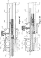
Figures 8A to 8D are detailed cross-sectional views of the outer and inner handle portions of the device shown inFigures 1A to 4A in progressive positions; -
Figure 9 is an isometric view of a component of the outer handle portion of the device shown inFigure 1A ; -
Figure 10 is a detailed isometric view showing the inner handle portion of the device shown inFigures 1A to 4A andFigures 8A to 8D ; -
Figures 11A and 11B are diagrammatic views showing a portion of the inner handle assembly shown inFigure 10 together with parts of a tip retriever actuator; -
Figure 12A is a detailed isometric view showing components of the device shown inFigure 1A , including a tip assembly slider; -
Figure 12B is a similar view to that ofFigure 12A , showing the components in an exploded view; -
Figure 12C shows a connection of trigger wires to a tip assembly slider, a proximal trigger wire release slider and a reducing trigger wire slider, all being components of the handle assembly shown inFigures 8A to 8D ; -
Figure 13 is a similar view to that ofFigure 11 , being a cross-sectional isometric view; -
Figure 14 is an isometric view of a tip retriever assembly which is a component of the device ofFigure 1A ; -
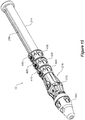
Figure 15 is an isometric view of another embodiment of the invention; -
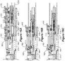
Figures 16A, 16B and 16C are cross-sectional views of the device shown inFigure 15 in progressive positions; -
Figure 17 is an isometric view of another embodiment of the invention; and -
Figures 18A, 18B and 18C are cross-sectional views of the device shown inFigure 17 in progressive positions. - Throughout this specification, the term "distal" with respect to a portion of the aorta, a deployment device or an endograft means the end of the aorta, deployment device or endograft further away in the direction of blood flow from the heart and the term "proximal" means the portion of the aorta deployment device or end of the endograft nearer to the heart in the direction of blood flow. Thus, in this description, the term "proximal" refers to the end of the delivery device that carries the endograft and that in use is located within the patient's vasculature at the treatment site. The term "distal" refers to the end of the delivery device that remains outside the patient during the procedure and that is manipulated by the physician.
- For the purposes of understanding the principles taught herein, reference will now be made to the embodiments illustrated in the drawings, and specific language will be used to describe them. It is to be understood that the Figures are, in some cases, schematic and do not show the various components in their actual scale. In many instances, the Figures show scaled up components to assist the reader.
- Referring now to
Figures 1A, 1B ,2A, 2B ,3A, 3B ,4A and 4B , there is shown adelivery device 10 for the percutaneous insertion into the artery (or other bodily lumen) of prostheses such as stents, stent grafts, catheters, cardiac leads, balloons, and the like, according to a first embodiment of the invention. It can be seen fromFigure 1B that thedelivery device 10 is loaded with an endograft orstent graft 5. - Referring first to
Figures 1A and 1B , it can be seen that the device has aproximal end 12 and adistal end 18. Thedelivery device 10 has anouter handle portion 210 located at itsdistal end 18. Theouter handle portion 210 has abody portion 218 and atrack 214 extending distally from thebody portion 218. Thedelivery device 10 also has aninner handle portion 220 which is shown inFigures 8A, 8B ,8C andFigure 10 . Theinner handle portion 220 is slidably moveable within, and with respect to, theouter handle portion 210 from a distal position to a proximal position, as can be seen progressively inFigures 8A and 8B . - A
tip assembly slider 410 is mounted on thetrack 214 for sliding movement with respect to thetrack 214, as is shown inFigure 1A and in further detail inFigures 12A and 12B . While various constructions may be used, it is convenient to provide a generally part-cylindrical track having a longitudinally extending slot 219 (the same as that shown inFigures 15 and17 ). Thetip assembly slider 410 is mounted on thetrack 214 and includes an outerarcuate portion 410a and an innerarcuate portion 610, shown most clearly inFigures 12A to 12C . Thetip assembly slider 410 is finger graspable for sliding movement with respect to thetrack 214. - A
tip assembly 100 is located at theproximal end 12 of thedelivery device 10, as is shown inFigures 1A and 1B . Further detail is shown inFigures 6A and 6B . In particular, it can be seen that an exposedstent 7 at a proximal end of theendograft 5 is captured by aproximal trigger wire 422, as is shown inFigure 6A . -
Figure 10 shows distal, proximal and reducing trigger wires (412, 422 and 432 respectively) and their terminal ends 413, 423 and 433 respectively. - The
delivery device 10 also has apusher catheter 300 extending proximally from theouter handle portion 210 towards thetip assembly 100, as can be seen inFigures 1B ,2B ,3B and4B . A distal end of the pusher catheter is attached to theouter handle portion 210. Aguide wire catheter 40 extends through theinner handle portion 220 and through thepusher catheter 300. Theguide wire catheter 40 is affixed at a distal end thereof to theinner handle portion 220 and is affixed at a proximal end thereof to the tip assembly100. Apin vice assembly 45, such as is shown inFigures 8A ,12A and 12B can be used. Such a pin vice assembly attaches to theinner handle portion 220, as is shown inFigures 8A and10 . Various pin vice constructions may be used, such as is described inUS-7,435,253 to Hartley referred to above where the pin vice has a screw cap which, when screwed in, clamps vice jaws against the thin walled metal tube (guide wire catheter). - In other embodiments, not shown, gluing, crimping or other attachment means may be used to secure the
guide wire catheter 40 to theinner handle portion 220. - The pusher catheter is also shown in a cross-sectional view in
Figure 7 where it is shown surrounded by asheath 510. Theparticular pusher catheter 300 of this embodiment has three longitudinally extending lumens. A first lumen is theguide wire lumen 390 and this lumen is off-set from the centre of the pusher catheter to allow for twoauxiliary lumens guide wire lumen 390 has passing through it theguide wire catheter 40 and coaxially around that the connector orretrieval catheter 114. Also in theguide wire lumen 390 are trigger wires, including aproximal trigger wire 422, a diameter reducing ties triggerwire 432, and adistal trigger wire 412. Furtherauxiliary guides 452 are also shown that may be used in some applications. - The
auxiliary lumen 394 has anaccess sheath 818 extending through it and thedilator 834 andguide wire 838 extend through theaccess sheath 818. Similarly, theauxiliary lumen 392 has anaccess sheath 922 extending through it and thedilator 942 andguide wire 946 extend through theaccess sheath 922. - The
sheath 510 is part of asheath assembly 500, as is shown inFigures 1A to 4A . These figures also show avalve body 540 at a distal end of thesheath assembly 500.Figure 4B shows aproximal end 512 of thesheath 510. - The
delivery device 10 also has anendograft receiving portion 50 for receiving theendograft 5 between thetip assembly 100 and the pusher catheter, as is shown inFigure 2B . It should be understood that 'between' means that at least a portion of theendograft receiving portion 50 is between thetip assembly 100 and the pusher catheter. - The
tip assembly slider 410 is operably connected to theinner handle portion 220 such that distal sliding movement of thetip assembly slider 410 slides thetip assembly 100 towards thepusher catheter 300. This is shown in the cross-sectional views ofFigures 8A to 8D ,10 ,12A, 12B ,13 and14 . - The
delivery device 10 further comprises thedistal trigger wire 412 referred to above for releasably retaining adistal end 9 of theendograft 5. A proximal end of thedistal trigger wire 412 is shown inFigure 5 .Figure 12C shows adistal end 413 of thedistal trigger wire 412 locked to and terminating within the tip assembly slider inner 610, which forms part of thetip assembly slider 410 shown inFigures 12A and 12B . The routeing of thedistal trigger wire 412 towards its distal end is shown inFigure 10. Figure 10 also shows the routeing of theproximal trigger wire 422 and the reducingtrigger wire 432 wire towards their respective distal ends 423 and 433. Distal movement of thetip assembly slider 410 pulls thedistal trigger wire 412 thereby releasing thedistal end 9 of theendograft 5. - Referring again to
Figures 1A and8A , it can be seen that thedevice 10 further comprises a proximal triggerwire release slider 420 mounted on thetrack 214 distally of thetip assembly slider 410, for sliding movement with respect to thetrack 214 from an initial position shown inFigures 1A ,2A and8A to a triggered position shown inFigures 3A and4A . The proximal triggerwire release slider 420 has an outerarcuate portion 420a and an innerarcuate portion 620, as is shown inFigure 12C . - A proximal end of the
proximal trigger wire 422 is shown inFigure 5 . Theproximal trigger wire 422 is provided for releasably retaining theproximal end 6 of theendograft 5 which is loadable on theendograft receiving portion 50, again shown inFigures 2B and5 . Distal movement of the proximal triggerwire release slider 420 pulls theproximal trigger wire 422 thereby releasing theproximal end 6 of theendograft 5. This can be seen in the movement from the positions shown fromFigures 6A to 6B . -
Figure 10 shows theproximal trigger wire 422 and itsdistal end 423 where it is locked to and terminates within the proximal triggerwire release slider 420, as shown inFigure 12C . - Referring again to
Figures 1A and8A , it can be seen that thedevice 10 further comprises a reducing triggerwire release slider 430 mounted on thetrack 214 distally of both thetip assembly slider 410 and the proximal triggerwire release slider 420, for sliding movement with respect to thetrack 214 from an initial position shown inFigures 1A ,2A and8A to a triggered position shown inFigures 3A and4A . The proximal triggerwire release slider 430 has an outerarcuate portion 430a and an innerarcuate portion 630. The reducingtrigger wire 432 is provided for holding theendograft 5 at a reduced diameter on theendograft receiving portion 50. Distal movement of the reducingtrigger wire 432 pulls reducingtrigger wire 432 thereby releasing theendograft 5 to expand radially. The precise arrangement for holding theendograft 5 at a reduced diameter on theendograft receiving portion 50 can vary. For instance, diameter reducing ties can be provided to achieve a reduction in the circumference of thestent graft 5 orother endograft 5, as is explained in the specification ofUS Patent Application serial Number 11/507,115 titled "Assembly of Stent Grafts" which is hereby incorporated in its entirety into this specification. Other reduction arrangements may be used such as that disclosed by Australian Patent No2012258395 - A proximal end of the reducing
trigger wire 432 is shown inFigure 5 .Figure 10 shows the reducingtrigger wire 432 and itsdistal end 433 where it is locked to and terminates within the reducing triggerwire release slider 430, as shown inFigure 12C . - As the drawings show, for instance
Figures 1A ,2A and8A , both thetip assembly slider 410 and the proximal triggerwire release slider 420 are mounted on thesame track 214. Furthermore, in their initial positions, shown in 1A, 2A and 8A, they are hard up against each other. The effect of this is that thetip assembly slider 410 engages the proximal triggerwire release slider 420 such that it cannot be moved distally until after the proximal triggerwire release slider 420 has been moved distally, for instance, to the position shown inFigures 3A and8B . - The
tip assembly 100 includes anose cone dilator 105, as indicated inFigure 3A . In the embodiment shown in the drawings discussed above, and as is shown inFigures 6A and 6B , the tip assembly further comprises atop cap 111 and aretriever 113. An open configuration for thetip assembly 100 is shown inFigure 6A and a closed configuration is shown inFigure 6B . Thetop cap 111 comprises adistally facing mouth 112, whereby in the open configuration, themouth 112 is open for receiving a proximal portion of theendograft 5 and in the closed configuration, themouth 112 is closed by theretriever 113. - Referring now to
Figure 14 , aconnector 114 extending from thetip assembly 100 to theinner handle portion 220 is shown. Theconnector 114 connects theretriever 113 to the proximal triggerwire release slider 420. Theconnector 114 includes adistal portion 115 slidably engageable with theinner handle portion 220, as shown inFigure 10 . Thedistal portion 115 is locked to the triggerwire release slider 420, as is shown inFigures 12A and 12B .Tabs 115' and 115" are captive within arecess 418 within halves of the triggerwire release slider 420.Tabs 115' and 115" are shown inFigure 12B , as is arecess 418 which receives tab 115'. - The
connector 114 described above comprises a tube portion coaxially mounted over theguide wire catheter 40. The tube portion joins thetip retriever 113 to thedistal portion 115.Figures 6A and 6B clearly show how theconnector 114 connects to thetip retriever 113 and how thetip retriever 113 moves within thetop cap 111. - With the first embodiment of the invention, the
connector 114 is a tube, for instance a tube made from PEEK (Polyether ether ketone). In other embodiments, theconnector 114 could be a metal tube, a wire or a plurality of wires for instance. Many possible constructions that are to transmit or convey a force may be suitable. - Turning now to
Figures 11A and 11B , aconnector receiver portion 204 of theinner handle portion 220 for receiving the connector distal end is shown. It can be seen that thereceiver portion 204 has two extreme positions. The first position is shown inFigure 8A and inFigure 11A . The second position is shown inFigure 8B and inFigure 11B . - The
connector receiver portion 204 locks to the connectordistal portion 115 when theinner handle portion 220 moves to the proximal position shown inFigures 8B and11B . While various locking arrangements may be used, with the first embodiment of the invention shown, theconnector receiver portion 204 comprises a rampedportion 205 and ashoulder portion 206. Theshoulder portion 206 abuts asurface 116, shown inFigure 11A , of the connectordistal portion 115 when theinner handle portion 220 is in the proximal position. - Referring to
Figures 8A to 8D and toFigure 10 , it can be seen that thedevice 10 further comprises atip assembly actuator 182 operably connected to theinner handle portion 220. Anactuator receiving portion 184 on the inner handle portion is also provided. With the embodiment illustrated, the actuator receiving portion comprises arack 184. The actuator receiving portion 184 (rack) is slidably drivable by thetip assembly actuator 182 in a proximal direction. Thetip assembly actuator 182 is actuatable to move theinner handle portion 220 proximally with respect to theouter handle portion 210 thereby actuating thetip assembly 100 from the first configuration shown inFigure 6A to the second configuration shown inFigure 6B . - Referring to the sequence of
Figures 8A to 8D , it can be seen that aninterlock 190 is provided. Thisinterlock 190 may be provided for some embodiments to prevent movement of the distal triggerwire release slider 410 to the triggered position until after theactuator 182 actuates thetip assembly 100 to the closed configuration shown inFigure 6B . - Referring to
Figure 9 , it can be seen that theouter handle portion 210 includes ahandle tail 215. Thehandle tail 215 hasrecesses locks Figure 8A , locks 415, 425 and 435 lock intorespective recesses interlock 190 referred to above and also shown inFigures 8A and 8B prevents rotation and unlocking oflock 415 when thedevice 10 is in the position shown inFigure 8A . When thetip assembly actuator 182 is actuated to move theinner handle portion 220 proximally with respect to theouter handle portion 210, as is progressively shown moving fromFigure 8A to 8B , theinterlock 190 is driven proximally away from thelock 415. This allows thelock 415 to be rotated and unlocked, as is shown in the movement fromFigure 8B to 8C . Its end is raised clear of the recess 211 (most clearly shown inFigures 9 and8D ) allowing the proximal triggerwire release slider 420, which is mounted on thetrack 214, to move distally as is shown inFigure 8D . - Another embodiment of the invention will now be described with reference to
Figures 15 ,16A, 16B and 16C . This embodiment differs from the embodiment ofFigures 1A to 14 primarily in relation to the tip assembly actuator and the locks located on the threesliders - Referring to
Figure 15 , as with the first-described embodiment, thedelivery device 10 has anouter handle portion 210 mounted to itsdistal end 18. Theouter handle portion 210 has abody portion 218 and atrack 214 extending distally frombody portion 218. Thedelivery device 10 of this embodiment also has aninner handle portion 220, which is shown inFigures 16A, 16B and 16C . Like with the first-described embodiment, theinner handle portion 220 is slidably movable within, and with respect to, theouter handle portion 210 from a distal position to a proximal position, as can be seen progressively inFigures 16A and 16B . - The
tip assembly 100 of this embodiment is preferably identical to thetip assembly 100 of the first-described embodiment and is located at theproximal end 12 of the delivery device, as is shown inFigures 1A and 1B . - The
delivery device 10 of this embodiment also has apusher catheter 300, not shown inFigures 16A, 16B and 16C . Thepusher catheter 300 is again identical to thepusher catheter 300 of the first embodiment of the invention as described above. - The
delivery device 10 also has anendograft receiving portion 50 for receiving anendograft 5, which is identical to theendograft receiving portion 50 of the first-described embodiment, as is shown inFigure 2B . - As with the first-described embodiment, the tip assembly slider 14 is operably connected to the
inner handle portion 220 such that distal sliding movement of the tip assembly slider 14 slides thetip assembly 100 towards thepusher catheter 300. This is shown in the cross-sectional views ofFigures 16A and 16B . - The trigger wires described with reference to the first-described embodiment are again the same with this embodiment.
- The
tip assembly slider 410 mounted on therack 214 is generally similar to that of thetip assembly slider 410 of the first-described embodiment, with a different lock employed. While thelock 415 of the first-described embodiment was operable by a twisting motion, in contrast, thelock 415 of this embodiment is actuated by a pushing action. - A
tip assembly actuator 182 for this embodiment can be seen inFigures 16A to 16D . Thistip assembly actuator 182 is operably connected to theinner handle portion 220. Thetip assembly actuator 182 is slidably movable with respect to theouter handle portion 210. This is in contrast to thetip assembly actuator 182 of the first-described embodiment which has a thumbwheel. Thetip assembly actuator 182 also includes apawl 183, as is illustrated inFigure 16A . Thepawl 183 engages therack 184, as can be seen inFigure 16C . Thepawl 183 pivots away from therack 184 when the distal triggerwire release slider 410 is slid in a distal direction away from theouter handle portion 210. - A further embodiment of the invention will now be described with reference to
Figures 17 ,18A, 18B and 18C . Thetip assembly actuator 182 of this embodiment is actuated by twisting around a longitudinal axis of thedevice 10. - Referring to
Figure 17 , thetip assembly actuator 182 is marked with the numeral 3 and is operated by twisting. The twisting motion moves apinion wheel 189 which engages arack 184. Twisting of thetip assembly actuator 182 therefore results in theinner handle portion 220 being pushed forward in a similar way to that of the first-described embodiment. - Use or operation of the
delivery device 10 will now be described. The operation will be described with reference to the first-described embodiment. - Referring first to
Figure 1A and its companionFigure 1B , thedelivery device 10 is shown together with asheath assembly 500 in a configuration ready for use. - Typically, one of the first major steps in a procedure undertaken by a vascular surgeon would be to introduce a guide wire into a blood vessel, such as the femoral artery, using the Seldinger technique. This technique involves creating a surgical opening in the vessel of the needle and inserting a wire guide into the vessel through a bore of the needle. The needle is then withdrawn leaving the guide wire in place. The
delivery device 10, as shown inFigures 1A and 1B , is then inserted over the guide wire and into the vessel. - Once the surgeon has positioned the
proximal end 12 of thedelivery device 10 near the target delivery area for theendograft 5, thesheath assembly 500 can be withdrawn to the position shown inFigures 2A and 2B . In this position, thesheath 510 of thesheath assembly 500 has been pulled back over the compressed endograft forstent graft 5 so as to expose it, as is shown inFigure 2B . This step is conducted by "grounding" theouter handle portion 210 while pulling thevalve body 540 of thesheath assembly 500 in a distal direction (away from the patient). - Typically, a next step in operating the
delivery device 10 would be causing the stent graft to expand from its reduced condition to an expanded condition. This next step causes removal of the reducingtrigger wire 432, the distal end of which can be seen most clearly inFigures 10 and12C . In order to commence this step, the surgeon rotates thelocking nob 435 from its position shown inFigure 8A . This releases thelock 435 from therecess 213 illustrated inFigure 9 . This allows the reducing triggerwire release slider 430 mounted on thetrack 214 to be slid in a distal direction from the position shown inFigure 1A to the position shown inFigure 2A to 3A . - When the surgeon slides the
slider 435 from the position shown inFigure 2A to the position shown inFigure 3A , thewire 432, as shown inFigure 10 , is pulled in a distal direction and its proximal end moves free from theendograft 5 allowing it to expand. It can also be seen that this step moves the reducing triggerwire release slider 430 from its position hard up against the adjacent proximal trigger wire release slider 420 (as shown inFigures 1A and2A ) to a position longitudinally spaced apart from adjacent proximal triggerwire release slider 420. - Typically, the next step in the procedure would be to release the
proximal trigger wire 422. This is done by twisting thelock 425 shown inFigure 8A so as to raise it out of engagement withcorresponding recess 212 shown inFigure 9 . After this has been done, theslider 420 can be finger gripped and slid in a distal direction along thetrack 214. Importantly, this cannot be done out of sequence. That is, theslider 420 cannot be moved before theslider 430. - The above described movement of the
slider 420 to the position shown inFigure 3A causes theproximal trigger wire 422 to be detached from thetip assembly 100, as is shown progressively betweenFigures 6A and 6B . - The next step is actuation of the
tip assembly actuator 182 shown inFigures 8A and 8B . The surgeon pushes on thethumbwheel 182 in the direction of the arrow shown adjacent thethumbwheel 182 inFigure 8B . This results in theinner handle portion 220 advancing in a proximal direction from the position shown inFigure 8A to the position shown inFigure 8B . The effect of this is that theguide wire catheter 40 and hence thenose cone dilator 105 and thetop cap 111 is also advanced in a proximal direction from the position shown inFigure 6A to the position shown inFigure 6B while theconnector 114 stays in the same position (as can be seen fromFigures 11A to 11B ). This results in the exposed stents 7of theendograft 5 being released to the position shown inFigure 6B while at the same time thetip retriever 113 seats against the distal end of thetop cap 111, as is shown inFigure 6B . - With the first-described embodiment, the rotation of the thumb wheel causes an
interlock 190 to move from the position shown inFigure 8A to the position shown inFigure 8B . In turn, this allows thelock 415 to be rotated from the position shown inFigure 8B to the position shown inFigure 8C . Once this has occurred, the lock is disengaged from therecess 212 shown inFigure 9 allowing theslider 410 to be moved from the position shown inFigure 8C to the position shown inFigure 8D and beyond in the direction of the arrow shown onFigure 8D . This movement causes theentire tip assembly 100 to move from the position shown inFigure 3B to the position shown inFigure 4B . That is, thetip assembly slider 410, being operably connected to theinner handle portion 210, slides distally so as to move thetip assembly 100 towards thepusher catheter 300. - After this step, typically the
sheath assembly 500 would be advanced in a proximal direction towards thetip assembly 100 into a position against or over thetip retriever 113 so that theentire delivery device 10 can safely be withdrawn through and out from within the deployedstent graft 5. - Operation of other embodiments of the invention, including the second and third described embodiments is largely similar. The differences in operation with the second-described embodiment is that the
actuator 182 is a slide mechanism rather than a thumb wheel and it is located on theouter handle portion 210 and is completely separate from theslider 410. Another difference with the second-described embodiment is that thelocks Figure 16A, 16B and 16C . - With the third-described embodiment, the operation is quite similar to that described with respect to the first-described embodiment, but the
actuator 182 is a twist mechanism integrated by the numeral 3 onFigure 17 . - Throughout the specification and the claims that follow, unless the context requires otherwise, the words "comprise" and "include" and variations such as "comprising" and "including" will be understood to imply the inclusion of a stated integer or group of integers, but not the exclusion of any other integer or group of integers.
- The reference to any prior art in this specification is not, and should not be taken as, an acknowledgement of any form of suggestion that such prior art forms part of the common general knowledge.
- It will be appreciated by those skilled in the art that the invention is not restricted in its use to the particular application described. Neither is the present invention restricted in its preferred embodiments with regard to the particular elements and/or features described or depicted herein. It will be appreciated that the invention is not limited to the embodiment or embodiments disclosed, but is capable of numerous rearrangements, modifications and substitutions without departing from the scope of the invention as set forth in the following claims.
- All optional and preferred features and modifications of the described embodiments and dependent claims are usable in all aspects of the invention taught herein. Furthermore, the individual features of the dependent claims, as well as all optional and preferred features and modifications of the described embodiments are combinable and interchangeable with one another.
- The disclosures in United States patent application number
62/594,911 2017/904881
Claims (15)
- An endovascular delivery device, for delivering an endograft, the device having a proximal end and a distal end, and comprising:an outer handle portion mounted to the distal end of the delivery device and including a body portion and a track extending distally from the body portion;an inner handle portion slidably moveable within and with respect to the outer handle portion from a distal position to a proximal position;a tip assembly slider mounted on the track for sliding movement with respect to the track;a tip assembly at the proximal end of the delivery device;a pusher catheter extending proximally from the outer handle assembly;a guide wire catheter extending through the inner handle portion and through the pusher catheter, the guide wire catheter being affixed at a distal end thereof to the inner handle portion and at a proximal end thereof to the tip assembly; andan endograft receiving portion for holding an endograft between the tip assembly and the pusher catheter;wherein the tip assembly slider is operably connected to the inner handle portion such that distal sliding movement of the tip assembly slider slides the tip assembly towards the pusher catheter.
- A device according to claim 1, comprising a distal trigger wire for releasably retaining a distal end of the endograft, whereby distal movement of the tip assembly slider pulls the distal trigger wire thereby releasing the distal end of the endograft.
- A device according to claim 1 or 2, comprising a proximal trigger wire release slider mounted on the track distally of the tip assembly slider, for sliding movement with respect to the track from an initial position to a triggered position; and a proximal trigger wire for releasably retaining a proximal end of the endograft loadable on the endograft receiving portion, whereby distal movement of the proximal trigger wire release slider pulls the proximal trigger wire thereby releasing the proximal end of the endograft.
- A device according to claim 3, wherein the tip assembly slider engages the proximal trigger wire release slider such that it cannot be moved distally until after the proximal trigger wire release slider has been moved distally.
- A device according to any preceding claim, wherein the tip assembly comprises a top cap and a retriever, the tip assembly having an open configuration and a closed configuration.
- A device according to claim 5, wherein the top cap comprises a distally facing mouth, whereby in the open configuration, the mouth is open for receiving a proximal portion of the endograft, and in the closed configuration, the mouth is closed by the retriever.
- A device according to any preceding claim, comprising a connector extending from the tip assembly to the inner handle portion, the connector including a distal portion slidably engageable with the inner handle portion.
- A device according to claim 7, wherein the inner handle portion comprises a connector receiver portion for receiving the connector distal portion.
- A device according to claim 8, whereby the connector receiver portion locks to the connector distal portion when the inner handle portion moves to the proximal position.
- A device according to claim 9, wherein the connector receiver portion comprises a ramped portion and a shoulder portion, the shoulder portion abutting a surface of the connector distal portion when the inner handle portion is in the proximal position.
- A device according to any one of claims 7 to 10, wherein the connector comprises a tube co-axially mounted over the guide wire catheter, the tube joining the tip retriever to the connector distal end.
- A device according to any preceding claim, comprising a tip assembly actuator operably connected to the inner handle portion; and an actuator receiving portion on the inner handle portion, the actuator receiving portion slidably drivable by the tip assembly actuator in a proximal direction.
- A device according to claim 12, wherein the actuator receiving portion comprises a rack.
- A device according to claim 13, wherein the tip assembly actuator is actuatable to move the inner handle portion proximally with respect to the outer handle portion, thereby actuating the tip assembly from the first configuration to the second configuration.
- An endovascular delivery device, for delivering an endograft, the device having a proximal end and a distal end, the delivery device comprising:an outer handle portion mounted to the distal end of the delivery device, the outer handle portion having a body portion and a track extending distally from the body portion;an inner handle portion, the inner handle portion slidably moveable within, and with respect to, the outer handle portion from a distal position to a proximal position;a tip assembly slider, mounted on the track for sliding movement with respect to the track;a tip assembly at the proximal end of the delivery device, the tip assembly comprising a top cap and a retriever, the tip assembly having an open configuration and a closed configuration, the top cap comprising a distally facing mouth, whereby in the open configuration, the mouth is open for receiving a proximal portion of the endograft, and in the closed configuration, the mouth is closed by the retriever;a connector extending from the tip assembly to the inner handle portion, the connector including a distal portion slidably engageable with the inner handle portion;a pusher catheter extending proximally from the outer handle assembly;a guide wire catheter extending through the inner handle portion and through the pusher catheter, the guide wire catheter being affixed at a distal end thereof to the inner handle portion and being affixed at a proximal end thereof to the tip assembly;an endograft receiving portion for receiving the endograft between the tip assembly and the pusher catheter;a distal trigger wire for releasably retaining a distal end of the endograft, whereby distal movement of the tip assembly slider pulls the distal trigger wire thereby releasing the distal end of the endograft; anda proximal trigger wire release slider mounted on the track distally of the tip assembly slider, for sliding movement with respect to the track from an initial position to a triggered position, wherein the tip assembly slider engages the proximal trigger wire release slider such that it cannot be moved distally until after the proximal trigger wire release slider has been moved distally;wherein the tip assembly slider is operably connected to the inner handle portion such that distal sliding movement of the tip assembly slider slides the tip assembly towards the pusher catheter.
Applications Claiming Priority (2)
| Application Number | Priority Date | Filing Date | Title |
|---|---|---|---|
| US201762594911P | 2017-12-05 | 2017-12-05 | |
| AU2017904881A AU2017904881A0 (en) | 2017-12-05 | An endograft delivery device assembly |
Publications (1)
| Publication Number | Publication Date |
|---|---|
| EP3494936A1 true EP3494936A1 (en) | 2019-06-12 |
Family
ID=63833947
Family Applications (1)
| Application Number | Title | Priority Date | Filing Date |
|---|---|---|---|
| EP18275158.6A Withdrawn EP3494936A1 (en) | 2017-12-05 | 2018-10-10 | Endograft delivery device assembly |
Country Status (2)
| Country | Link |
|---|---|
| US (1) | US11083606B2 (en) |
| EP (1) | EP3494936A1 (en) |
Cited By (1)
| Publication number | Priority date | Publication date | Assignee | Title |
|---|---|---|---|---|
| US11141297B2 (en) | 2018-12-19 | 2021-10-12 | Cook Medical Technologies Llc | Endovascular delivery device having an improved top-cap assembly |
Families Citing this family (6)
| Publication number | Priority date | Publication date | Assignee | Title |
|---|---|---|---|---|
| JP7145757B2 (en) | 2015-10-12 | 2022-10-03 | リフロー メディカル インコーポレイテッド | Stents with protruding drug delivery features and related systems and methods |
| AU2018249936B2 (en) | 2017-04-06 | 2024-05-02 | Reflow Medical, Inc. | Delivery systems for stents having protruding features |
| US11648139B2 (en) | 2018-10-08 | 2023-05-16 | Reflow Medical, Inc. | Delivery systems for stents having protruding features |
| US11166833B2 (en) | 2019-04-30 | 2021-11-09 | Cook Medical Technologies Llc | Line pull assembly for a prosthetic delivery device |
| US11992241B2 (en) | 2020-01-31 | 2024-05-28 | DePuy Synthes Products, Inc. | System to assist delivery of a mechanical intravascular treatment device |
| US20240016631A1 (en) * | 2022-07-12 | 2024-01-18 | Cook Medical Technologies Llc | An endograft delivery device assembly |
Citations (4)
| Publication number | Priority date | Publication date | Assignee | Title |
|---|---|---|---|---|
| WO2008042270A1 (en) * | 2006-09-28 | 2008-04-10 | Med Institute, Inc. | Endovascular delivery device |
| US7435253B1 (en) | 1997-05-26 | 2008-10-14 | William A. Cook Australia Pty Ltd | Prosthesis and a method and means of deploying a prosthesis |
| WO2011159504A1 (en) * | 2010-06-15 | 2011-12-22 | Cook Medical Technologies Llc | Pre-loaded multiport delivery device |
| AU2012258395B1 (en) | 2012-11-27 | 2013-03-28 | Cook Medical Technologies Llc | Assembly of stent grafts with diameter reducing ties |
Family Cites Families (22)
| Publication number | Priority date | Publication date | Assignee | Title |
|---|---|---|---|---|
| WO1996036297A1 (en) | 1995-05-19 | 1996-11-21 | Kanji Inoue | Transplantation instrument, method of bending same and method of transplanting same |
| US6878161B2 (en) | 1996-01-05 | 2005-04-12 | Medtronic Vascular, Inc. | Stent graft loading and deployment device and method |
| EP1117341B1 (en) | 1998-09-30 | 2004-12-29 | Bard Peripheral Vascular, Inc. | Delivery mechanism for implantable stent |
| US20090099650A1 (en) * | 2001-11-28 | 2009-04-16 | Lee Bolduc | Devices, systems, and methods for endovascular staple and/or prosthesis delivery and implantation |
| US7074230B2 (en) | 2002-02-21 | 2006-07-11 | Olson Richard C | Ear cleaning device |
| US20060129181A1 (en) | 2004-12-13 | 2006-06-15 | Callol Joseph R | Retrieval device with retractable dilator tip |
| US8172895B2 (en) | 2005-08-18 | 2012-05-08 | Cook Medical Technologies Llc | Design and assembly of fenestrated stent grafts |
| JP5250748B2 (en) * | 2006-06-02 | 2013-07-31 | ウィリアム・エイ・クック・オーストラリア・プロプライエタリー・リミテッド | Multiport delivery device |
| US20110077731A1 (en) | 2009-09-25 | 2011-03-31 | Abbott Cardiovascular Systems Inc. | Multiple stent delivery system |
| JP5891236B2 (en) | 2010-11-17 | 2016-03-22 | ボストン サイエンティフィック サイムド,インコーポレイテッドBoston Scientific Scimed,Inc. | Stent delivery system |
| CN103379937B (en) | 2011-02-25 | 2016-09-07 | C·R·巴德股份有限公司 | Medical component insertion device including retractible pin |
| US8951243B2 (en) | 2011-12-03 | 2015-02-10 | Boston Scientific Scimed, Inc. | Medical device handle |
| JP6326648B2 (en) | 2012-08-10 | 2018-05-23 | アルツラ メディカル インコーポレイテッド | Stent delivery system and related method |
| US20140121750A1 (en) | 2012-10-31 | 2014-05-01 | Cook Medical Technologies Llc | Fixation Process For Nesting Stents |
| US9717614B2 (en) | 2014-02-16 | 2017-08-01 | Cook Medical Technologies Llc | Deployment handle for a prosthesis delivery device |
| US9486350B2 (en) | 2014-03-31 | 2016-11-08 | Medtronic Vascular, Inc. | Stent-graft delivery system having handle mechanism for two-stage tip release |
| US9849016B2 (en) | 2014-04-04 | 2017-12-26 | W. L. Gore & Associates, Inc. | Method of manufacturing a deployment handle of a medical device deployment system |
| EP3145453B1 (en) | 2014-05-21 | 2021-01-20 | Boston Scientific Scimed, Inc. | Stent delivery system |
| US10058441B2 (en) | 2015-05-20 | 2018-08-28 | Cook Medical Technologies Llc | Deployment handle for a pre-loaded iliac prosthesis delivery device |
| CN105943212B (en) | 2015-12-23 | 2018-08-14 | 微创心脉医疗科技(上海)有限公司 | Stent delivery system and its Handleset |
| US10806931B2 (en) | 2016-12-27 | 2020-10-20 | Cardiac Pacemakers, Inc. | Delivery devices and methods for leadless cardiac devices |
| US11166833B2 (en) | 2019-04-30 | 2021-11-09 | Cook Medical Technologies Llc | Line pull assembly for a prosthetic delivery device |
-
2018
- 2018-10-10 EP EP18275158.6A patent/EP3494936A1/en not_active Withdrawn
- 2018-11-09 US US16/186,174 patent/US11083606B2/en active Active
Patent Citations (4)
| Publication number | Priority date | Publication date | Assignee | Title |
|---|---|---|---|---|
| US7435253B1 (en) | 1997-05-26 | 2008-10-14 | William A. Cook Australia Pty Ltd | Prosthesis and a method and means of deploying a prosthesis |
| WO2008042270A1 (en) * | 2006-09-28 | 2008-04-10 | Med Institute, Inc. | Endovascular delivery device |
| WO2011159504A1 (en) * | 2010-06-15 | 2011-12-22 | Cook Medical Technologies Llc | Pre-loaded multiport delivery device |
| AU2012258395B1 (en) | 2012-11-27 | 2013-03-28 | Cook Medical Technologies Llc | Assembly of stent grafts with diameter reducing ties |
Cited By (1)
| Publication number | Priority date | Publication date | Assignee | Title |
|---|---|---|---|---|
| US11141297B2 (en) | 2018-12-19 | 2021-10-12 | Cook Medical Technologies Llc | Endovascular delivery device having an improved top-cap assembly |
Also Published As
| Publication number | Publication date |
|---|---|
| US20190167456A1 (en) | 2019-06-06 |
| US11083606B2 (en) | 2021-08-10 |
Similar Documents
| Publication | Publication Date | Title |
|---|---|---|
| US11083606B2 (en) | Endograft delivery device assembly | |
| EP2490629B1 (en) | Rotational controlled deployment device | |
| US11123208B2 (en) | Prosthesis delivery system with tip travel limiter and method of use | |
| EP2175811B1 (en) | Deployment device | |
| EP3138538B1 (en) | Split sheath prosthesis deployment system with divided tip | |
| EP3028680B1 (en) | Delivery device handle assembly for the sequential deployment of a prosthesis | |
| EP2547293B1 (en) | Introducer with extension | |
| EP2391310B1 (en) | Preloaded stent graft delivery device | |
| EP2893907B1 (en) | A delivery device for an insertable medical device | |
| EP3351217A1 (en) | Prosthesis delivery device with detachable connector assembly | |
| US20040093056A1 (en) | Medical appliance delivery apparatus and method of use | |
| US11166833B2 (en) | Line pull assembly for a prosthetic delivery device | |
| EP3292844B1 (en) | Prosthesis deployment system | |
| US11051961B2 (en) | Deployment handle with stabilizing rail for a pre-loaded prosthesis delivery device | |
| EP3510977A1 (en) | An endoluminal delivery device assembly | |
| AU2018282309B1 (en) | An endovascular delivery device having an improved top-cap assembly | |
| EP3064177B1 (en) | Delivery device with an extension sheath | |
| AU2021200270B1 (en) | A line puller mechanism for an endo-luminal delivery device |
Legal Events
| Date | Code | Title | Description |
|---|---|---|---|
| PUAI | Public reference made under article 153(3) epc to a published international application that has entered the european phase |
Free format text: ORIGINAL CODE: 0009012 |
|
| STAA | Information on the status of an ep patent application or granted ep patent |
Free format text: STATUS: THE APPLICATION HAS BEEN PUBLISHED |
|
| AK | Designated contracting states |
Kind code of ref document: A1 Designated state(s): AL AT BE BG CH CY CZ DE DK EE ES FI FR GB GR HR HU IE IS IT LI LT LU LV MC MK MT NL NO PL PT RO RS SE SI SK SM TR |
|
| AX | Request for extension of the european patent |
Extension state: BA ME |
|
| STAA | Information on the status of an ep patent application or granted ep patent |
Free format text: STATUS: REQUEST FOR EXAMINATION WAS MADE |
|
| 17P | Request for examination filed |
Effective date: 20191203 |
|
| RBV | Designated contracting states (corrected) |
Designated state(s): AL AT BE BG CH CY CZ DE DK EE ES FI FR GB GR HR HU IE IS IT LI LT LU LV MC MK MT NL NO PL PT RO RS SE SI SK SM TR |
|
| STAA | Information on the status of an ep patent application or granted ep patent |
Free format text: STATUS: EXAMINATION IS IN PROGRESS |
|
| 17Q | First examination report despatched |
Effective date: 20210512 |
|
| GRAP | Despatch of communication of intention to grant a patent |
Free format text: ORIGINAL CODE: EPIDOSNIGR1 |
|
| STAA | Information on the status of an ep patent application or granted ep patent |
Free format text: STATUS: GRANT OF PATENT IS INTENDED |
|
| GRAJ | Information related to disapproval of communication of intention to grant by the applicant or resumption of examination proceedings by the epo deleted |
Free format text: ORIGINAL CODE: EPIDOSDIGR1 |
|
| STAA | Information on the status of an ep patent application or granted ep patent |
Free format text: STATUS: EXAMINATION IS IN PROGRESS |
|
| INTG | Intention to grant announced |
Effective date: 20240129 |
|
| GRAP | Despatch of communication of intention to grant a patent |
Free format text: ORIGINAL CODE: EPIDOSNIGR1 |
|
| STAA | Information on the status of an ep patent application or granted ep patent |
Free format text: STATUS: GRANT OF PATENT IS INTENDED |
|
| INTC | Intention to grant announced (deleted) | ||
| INTG | Intention to grant announced |
Effective date: 20240301 |
|
| STAA | Information on the status of an ep patent application or granted ep patent |
Free format text: STATUS: THE APPLICATION IS DEEMED TO BE WITHDRAWN |
|
| 18D | Application deemed to be withdrawn |
Effective date: 20240702 |