EP3494907A2 - Medical micro-robot and micro-robot system having the same - Google Patents
Medical micro-robot and micro-robot system having the same Download PDFInfo
- Publication number
- EP3494907A2 EP3494907A2 EP19154970.8A EP19154970A EP3494907A2 EP 3494907 A2 EP3494907 A2 EP 3494907A2 EP 19154970 A EP19154970 A EP 19154970A EP 3494907 A2 EP3494907 A2 EP 3494907A2
- Authority
- EP
- European Patent Office
- Prior art keywords
- drilling
- medicine
- spiral
- micro robot
- spiral coupling
- Prior art date
- Legal status (The legal status is an assumption and is not a legal conclusion. Google has not performed a legal analysis and makes no representation as to the accuracy of the status listed.)
- Granted
Links
Images
Classifications
-
- A—HUMAN NECESSITIES
- A61—MEDICAL OR VETERINARY SCIENCE; HYGIENE
- A61M—DEVICES FOR INTRODUCING MEDIA INTO, OR ONTO, THE BODY; DEVICES FOR TRANSDUCING BODY MEDIA OR FOR TAKING MEDIA FROM THE BODY; DEVICES FOR PRODUCING OR ENDING SLEEP OR STUPOR
- A61M5/00—Devices for bringing media into the body in a subcutaneous, intra-vascular or intramuscular way; Accessories therefor, e.g. filling or cleaning devices, arm-rests
- A61M5/14—Infusion devices, e.g. infusing by gravity; Blood infusion; Accessories therefor
- A61M5/142—Pressure infusion, e.g. using pumps
- A61M5/145—Pressure infusion, e.g. using pumps using pressurised reservoirs, e.g. pressurised by means of pistons
- A61M5/1452—Pressure infusion, e.g. using pumps using pressurised reservoirs, e.g. pressurised by means of pistons pressurised by means of pistons
-
- A—HUMAN NECESSITIES
- A61—MEDICAL OR VETERINARY SCIENCE; HYGIENE
- A61B—DIAGNOSIS; SURGERY; IDENTIFICATION
- A61B17/00—Surgical instruments, devices or methods
- A61B17/32—Surgical cutting instruments
- A61B17/3205—Excision instruments
- A61B17/3207—Atherectomy devices working by cutting or abrading; Similar devices specially adapted for non-vascular obstructions
-
- A—HUMAN NECESSITIES
- A61—MEDICAL OR VETERINARY SCIENCE; HYGIENE
- A61B—DIAGNOSIS; SURGERY; IDENTIFICATION
- A61B17/00—Surgical instruments, devices or methods
- A61B17/32—Surgical cutting instruments
- A61B17/3205—Excision instruments
- A61B17/3207—Atherectomy devices working by cutting or abrading; Similar devices specially adapted for non-vascular obstructions
- A61B17/320758—Atherectomy devices working by cutting or abrading; Similar devices specially adapted for non-vascular obstructions with a rotating cutting instrument, e.g. motor driven
-
- A—HUMAN NECESSITIES
- A61—MEDICAL OR VETERINARY SCIENCE; HYGIENE
- A61B—DIAGNOSIS; SURGERY; IDENTIFICATION
- A61B34/00—Computer-aided surgery; Manipulators or robots specially adapted for use in surgery
- A61B34/30—Surgical robots
-
- A—HUMAN NECESSITIES
- A61—MEDICAL OR VETERINARY SCIENCE; HYGIENE
- A61B—DIAGNOSIS; SURGERY; IDENTIFICATION
- A61B34/00—Computer-aided surgery; Manipulators or robots specially adapted for use in surgery
- A61B34/70—Manipulators specially adapted for use in surgery
- A61B34/73—Manipulators for magnetic surgery
-
- A—HUMAN NECESSITIES
- A61—MEDICAL OR VETERINARY SCIENCE; HYGIENE
- A61M—DEVICES FOR INTRODUCING MEDIA INTO, OR ONTO, THE BODY; DEVICES FOR TRANSDUCING BODY MEDIA OR FOR TAKING MEDIA FROM THE BODY; DEVICES FOR PRODUCING OR ENDING SLEEP OR STUPOR
- A61M31/00—Devices for introducing or retaining media, e.g. remedies, in cavities of the body
-
- A—HUMAN NECESSITIES
- A61—MEDICAL OR VETERINARY SCIENCE; HYGIENE
- A61B—DIAGNOSIS; SURGERY; IDENTIFICATION
- A61B17/00—Surgical instruments, devices or methods
- A61B17/00234—Surgical instruments, devices or methods for minimally invasive surgery
-
- A—HUMAN NECESSITIES
- A61—MEDICAL OR VETERINARY SCIENCE; HYGIENE
- A61B—DIAGNOSIS; SURGERY; IDENTIFICATION
- A61B17/00—Surgical instruments, devices or methods
- A61B17/22—Implements for squeezing-off ulcers or the like on inner organs of the body; Implements for scraping-out cavities of body organs, e.g. bones; for invasive removal or destruction of calculus using mechanical vibrations; for removing obstructions in blood vessels, not otherwise provided for
-
- A—HUMAN NECESSITIES
- A61—MEDICAL OR VETERINARY SCIENCE; HYGIENE
- A61B—DIAGNOSIS; SURGERY; IDENTIFICATION
- A61B17/00—Surgical instruments, devices or methods
- A61B2017/00017—Electrical control of surgical instruments
- A61B2017/00137—Details of operation mode
-
- A—HUMAN NECESSITIES
- A61—MEDICAL OR VETERINARY SCIENCE; HYGIENE
- A61B—DIAGNOSIS; SURGERY; IDENTIFICATION
- A61B17/00—Surgical instruments, devices or methods
- A61B17/00234—Surgical instruments, devices or methods for minimally invasive surgery
- A61B2017/00345—Micromachines, nanomachines, microsystems
-
- A—HUMAN NECESSITIES
- A61—MEDICAL OR VETERINARY SCIENCE; HYGIENE
- A61B—DIAGNOSIS; SURGERY; IDENTIFICATION
- A61B17/00—Surgical instruments, devices or methods
- A61B2017/00367—Details of actuation of instruments, e.g. relations between pushing buttons, or the like, and activation of the tool, working tip, or the like
- A61B2017/00398—Details of actuation of instruments, e.g. relations between pushing buttons, or the like, and activation of the tool, working tip, or the like using powered actuators, e.g. stepper motors, solenoids
-
- A—HUMAN NECESSITIES
- A61—MEDICAL OR VETERINARY SCIENCE; HYGIENE
- A61B—DIAGNOSIS; SURGERY; IDENTIFICATION
- A61B17/00—Surgical instruments, devices or methods
- A61B2017/00367—Details of actuation of instruments, e.g. relations between pushing buttons, or the like, and activation of the tool, working tip, or the like
- A61B2017/00411—Details of actuation of instruments, e.g. relations between pushing buttons, or the like, and activation of the tool, working tip, or the like actuated by application of energy from an energy source outside the body
-
- A—HUMAN NECESSITIES
- A61—MEDICAL OR VETERINARY SCIENCE; HYGIENE
- A61B—DIAGNOSIS; SURGERY; IDENTIFICATION
- A61B17/00—Surgical instruments, devices or methods
- A61B2017/00831—Material properties
- A61B2017/00893—Material properties pharmaceutically effective
-
- A—HUMAN NECESSITIES
- A61—MEDICAL OR VETERINARY SCIENCE; HYGIENE
- A61B—DIAGNOSIS; SURGERY; IDENTIFICATION
- A61B17/00—Surgical instruments, devices or methods
- A61B17/22—Implements for squeezing-off ulcers or the like on inner organs of the body; Implements for scraping-out cavities of body organs, e.g. bones; for invasive removal or destruction of calculus using mechanical vibrations; for removing obstructions in blood vessels, not otherwise provided for
- A61B2017/22082—Implements for squeezing-off ulcers or the like on inner organs of the body; Implements for scraping-out cavities of body organs, e.g. bones; for invasive removal or destruction of calculus using mechanical vibrations; for removing obstructions in blood vessels, not otherwise provided for after introduction of a substance
- A61B2017/22084—Implements for squeezing-off ulcers or the like on inner organs of the body; Implements for scraping-out cavities of body organs, e.g. bones; for invasive removal or destruction of calculus using mechanical vibrations; for removing obstructions in blood vessels, not otherwise provided for after introduction of a substance stone- or thrombus-dissolving
-
- A—HUMAN NECESSITIES
- A61—MEDICAL OR VETERINARY SCIENCE; HYGIENE
- A61B—DIAGNOSIS; SURGERY; IDENTIFICATION
- A61B17/00—Surgical instruments, devices or methods
- A61B17/22—Implements for squeezing-off ulcers or the like on inner organs of the body; Implements for scraping-out cavities of body organs, e.g. bones; for invasive removal or destruction of calculus using mechanical vibrations; for removing obstructions in blood vessels, not otherwise provided for
- A61B2017/22094—Implements for squeezing-off ulcers or the like on inner organs of the body; Implements for scraping-out cavities of body organs, e.g. bones; for invasive removal or destruction of calculus using mechanical vibrations; for removing obstructions in blood vessels, not otherwise provided for for crossing total occlusions, i.e. piercing
-
- A—HUMAN NECESSITIES
- A61—MEDICAL OR VETERINARY SCIENCE; HYGIENE
- A61B—DIAGNOSIS; SURGERY; IDENTIFICATION
- A61B34/00—Computer-aided surgery; Manipulators or robots specially adapted for use in surgery
- A61B34/20—Surgical navigation systems; Devices for tracking or guiding surgical instruments, e.g. for frameless stereotaxis
- A61B2034/2046—Tracking techniques
- A61B2034/2065—Tracking using image or pattern recognition
-
- A—HUMAN NECESSITIES
- A61—MEDICAL OR VETERINARY SCIENCE; HYGIENE
- A61B—DIAGNOSIS; SURGERY; IDENTIFICATION
- A61B34/00—Computer-aided surgery; Manipulators or robots specially adapted for use in surgery
- A61B34/30—Surgical robots
- A61B2034/301—Surgical robots for introducing or steering flexible instruments inserted into the body, e.g. catheters or endoscopes
-
- A—HUMAN NECESSITIES
- A61—MEDICAL OR VETERINARY SCIENCE; HYGIENE
- A61B—DIAGNOSIS; SURGERY; IDENTIFICATION
- A61B34/00—Computer-aided surgery; Manipulators or robots specially adapted for use in surgery
- A61B34/30—Surgical robots
- A61B2034/303—Surgical robots specifically adapted for manipulations within body lumens, e.g. within lumen of gut, spine, or blood vessels
-
- A—HUMAN NECESSITIES
- A61—MEDICAL OR VETERINARY SCIENCE; HYGIENE
- A61B—DIAGNOSIS; SURGERY; IDENTIFICATION
- A61B90/00—Instruments, implements or accessories specially adapted for surgery or diagnosis and not covered by any of the groups A61B1/00 - A61B50/00, e.g. for luxation treatment or for protecting wound edges
- A61B90/36—Image-producing devices or illumination devices not otherwise provided for
- A61B90/37—Surgical systems with images on a monitor during operation
- A61B2090/376—Surgical systems with images on a monitor during operation using X-rays, e.g. fluoroscopy
-
- A—HUMAN NECESSITIES
- A61—MEDICAL OR VETERINARY SCIENCE; HYGIENE
- A61B—DIAGNOSIS; SURGERY; IDENTIFICATION
- A61B90/00—Instruments, implements or accessories specially adapted for surgery or diagnosis and not covered by any of the groups A61B1/00 - A61B50/00, e.g. for luxation treatment or for protecting wound edges
Definitions
- the present invention relates to a medical micro robot, and more particularly, a medical micro robot capable of putting a medicine for dissolving a thrombus into a blood vessel and capable of drilling the thrombus, and a micro robot system having the micro robot.
- a micro robot for a blood vessel treatment may create only mechanical drilling motion in order to treat the blood vessel.
- the blood vessel treatment only using the mechanical drilling motion may be relatively easily implemented because an operating method thereof is simple.
- the catheter is difficult to be applied to complicated blood vessels, and the success of the surgical procedure is greatly dictated by the skill of the medical practitioner.
- the micro robot which has been developed up to now, is mainly used to treat a clogged blood vessel by using mechanical drilling motion.
- a thrombolytic agent is a medicine that may biochemically dissolve the thrombus, and the blood vessel disease may be effectively treated when the thrombolytic agent is used together with the mechanical drilling motion.
- An object of the present invention is to provide a medical micro robot, which may form a spiral coupling structure, perform forward movement, and drill a thrombus, and may also inject a medicine for dissolving the thrombus, and a micro robot system having the micro robot.
- An exemplary embodiment of the present invention provides a micro robot comprising: a drilling body (100) which has a drilling tip (110) formed at an end thereof; and a spiral coupling body (200) which has a magnet disposed therein, and is spirally coupled to an outer circumference of the drilling body (100), and wherein a medicine accommodating space (130), which has a hollow shape and accommodates a medicine, is formed in the drilling body (100).
- a medicine injection hole(120) through which the accommodated medicine is injected to the outside may be formed at the drilling tip(110).
- the spiral coupling body(200) may include: a piston body(210) which is disposed to be fitted into the medicine accommodating space(130) in order to pump the medicine; and a spiral coil(220) which is formed at an end portion of the piston body(210) and spirally coupled to a spiral protrusion(140) formed on the outer circumference of the drilling body (100).
- a magnet slot(230) into which the magnet(400) is fitted and installed may be formed in the piston body(210).
- the magnet slot(230) may be formed as a cylindrical hole and the magnet(400) is formed in a cylindrical bar shape.
- the end portion of the piston body(210) may be formed in a convex shape.
- An exemplary embodiment of the present invention provides a micro robot system comprising; a micro robot(1) which has a drilling body(100) and a spiral coupling body (200); and a system control unit (300) which allows the drilling body (100) and the spiral coupling body(200) to spirally move simultaneously or allows the spiral coupling body (200) to spirally move around the drilling body(100) by providing rotational magnetic field to the magnet, wherein the spiral coupling body (200) has a magnet disposed therein, and is spirally coupled to an outer circumference of the drilling body (100).
- the drilling body(100) may have a drilling tip (110) formed at an end thereof, a medicine accommodating space (130) which has a hollow shape and accommodates a medicine and is formed in the drilling body(100), and a medicine injection hole(120) through which the accommodated medicine is injected to the outside, and formed at an end portion of the drilling tip(110).
- the spiral coupling body(200) may include: a piston body(210) which is disposed to be fitted into the medicine accommodating space(130) in order to pump the medicine; and a spiral coil(220) which is formed at an end portion of the piston body(210) and spirally coupled to a spiral protrusion formed on the outer circumference of the drilling body (100).
- the drilling body(100) and the spiral coupling body(200) spirally may move simultaneously in the forward movement mode and the rearward movement mode, the spiral coupling body(200) spirally moves in a state in which the spiral coupling body(200) is partially and spirally coupled to the outer circumference of the drilling body(100) and the piston body(210) pumps the medicine accommodated in the medicine accommodating space(130) and discharges the medicine through the medicine injection hole in the medicine injection mode, and the drilling body(100) spirally moves in a state in which the spiral coupling body(200) is completely spirally coupled to the outer circumference of the drilling body(100) in the drilling mode.
- the system control unit(300) may control an operation of a magnetic field generating unit that generates the rotational magnetic field, a forward movement mode or a rearward movement mode, a medicine injection mode, a drilling mode are set to the system control unit(300), the system control unit(300) satisfies a condition of T H 1 r + T H 2 r ⁇ T H 1 m ⁇ I H 1 + I H 2 I H 2 T H 1 + H 2 max . f ⁇ I H 1 I H 2 T H 2 r + T H 1 r when the forward movement and the rearward movement mode are carried out, satisfies a condition of I H 1 + I H 2 I H 2 T H 1 + H 2 max .
- T H 1 m is magnetic torque applied to the drilling body(100) by the rotational magnetic field
- T H 1 r is resistance torque generated by the spiral motion of the drilling body(100)
- T H 2 r is resistance torque generated by the spiral motion of the spiral coupling body(200)
- the I H1 is rotational inertia moment of the drilling body(100)
- the I H2 is rotational inertia moment of the spiral coupling body(200)
- T H 1 + H 2 max is maximum friction torque generated between the drilling body(100) and the spiral coupling body(200).
- the spiral coupling structure may be formed, the forward movement may be performed, the thrombus may be drilled, and the medicine for dissolving the thrombus may be injected.
- the micro robot may be applied to various diseases of the human body in addition to the treatment of the blood vessel, thereby enabling low-priced and high-efficiency treatment with minimum invasion.
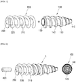
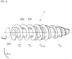
- FIG. 1 is a coupled perspective view illustrating a medical micro robot of the present invention
- FIG. 2 is an exploded perspective view illustrating the medical micro robot of the present invention
- FIG. 3 is a view illustrating torque applied to the medical micro robot of the present invention.
- FIGS. 1 and 2 A configuration of the medical micro robot of the present invention will be described with reference to FIGS. 1 and 2 .
- a medical micro robot 1 of the present invention broadly includes a drilling body 100, a spiral coupling body 200, a system control unit 300.
- the drilling body 100 is formed in a hollow shape, and a diameter at one end or the other end may be gradually decreased.
- a drilling tip 110 is formed at the end of the drilling body 100.
- the drilling body 100 is formed in a hollow shape, and has a space formed therein.
- the space may be a medicine accommodating space 130 that may receive or accommodate a medicine.
- the medicine may be a medicine for dissolving the thrombus formed in a blood vessel, or may be a medicine for various purposes.
- the medicine accommodating space 130 provides a space into which a piston body 210 of the spiral coupling body 200, which will be described below, is fitted such that the piston body 210 may be moved leftward and rightward in the medicine accommodating space 130.
- a medicine injection hole 120 which exposes the medicine accommodating space 130 to the outside and allows the medicine to be injected to the outside, is formed at the end of the drilling body 100, particularly, at a central portion of the drilling tip 110.
- a spiral protrusion 140 which is formed at a predetermined pitch, protrudes from an outer circumference of the drilling body 100.
- the spiral coupling body 200 includes a piston body 210 and a spiral coil 220. An end of the piston body 210 is convexly formed.
- the piston body 210 is fitted and disposed into the medicine accommodating space 130 in order to pump the medicine.
- One end of the spiral coil 220 is formed to be fixed to the piston body 210, and the spiral coil 220 is formed in a spiral shape having a predetermined pitch along the other end.
- the spiral coil 220 may be disposed to be spirally coupled to a spiral groove 150 between threads of the spiral protrusion 140 formed on the outer circumference of the drilling body 100.
- the spiral coupling body 200 may be spirally coupled to the drilling body 100 so that the spiral coupling body 200 moves forward or rearward at the outer circumference of the drilling body 100 as the spiral coil 220 is spirally coupled to the spiral groove 150 and moved forward or rearward.
- spiral coupling body 200 has a magnet slot 230.
- the magnet slot 230 is formed to have a predetermined depth from one end side of the piston body 210.
- the magnet slot 230 may be formed to correspond to a shape of a magnet, and for example, the magnet slot 230 may be formed as a cylindrical groove.
- a magnet 400 having a cylindrical bar shape may be fitted, fixed, and installed into the magnet slot 230.
- a pitch between the threads of the spiral protrusion 140 may be greater than a thickness of the spiral coil 220.
- a system control unit 300 controls an operation of a magnetic field generating unit (not illustrated) that generates a rotational magnetic field.
- the drilling body 100 may create x-axis direction spiral motion by an external rotational magnetic field that rotates in an x-axis direction.
- the spiral coupling body 200 and the drilling body 100 are simultaneously rotated by rotational friction torque between the drilling body 100 and the spiral coupling body 200, or the motion, which allows the drilling body 100 and the spiral coupling body 200 to be spirally coupled to each other, may be created.
- Magnetic torque applied to the drilling body 100 in the external magnetic field may be expressed by Equation 1.
- T H 1 m m ⁇ B
- T H 1 m is magnetic torque applied to the drilling body 100 by the external magnetic field
- m is magnetic moment of the magnet
- B is intensity of the external magnetic field
- B 0 intensity of the external rotational magnetic field
- f is a frequency of the external rotational magnetic field
- t is time.
- T H 1 m is magnetic torque applied to the drilling body 100 by the rotational magnetic field.
- T H 1 r is resistance torque generated by the spiral motion of the drilling body 100.
- T H 2 r is resistance torque generated by the spiral motion of the spiral coupling body 200.
- I H1 is rotational inertia moment of the drilling body 100
- I H2 is rotational inertia moment of the spiral coupling body 200
- f is maximum friction torque generated between the drilling body 100 and the spiral coupling body 200.
- ⁇ H1 is an angular acceleration of the drilling body 100
- ⁇ H 2 is an angular acceleration of the spiral coupling body 200.
- the magnetic torque applied to the drilling body 100 is applied within a range of the following Expression 5, the drilling body 100 and the spiral coupling body 200 simultaneously generates spiral motion by the external rotational magnetic field.
- T H 1 + H 2 max . f is maximum friction torque generated between the drilling body 100 and the spiral coupling body 200.
- the partially coupled micro robot 1 may accommodate the medicine in the medicine accommodating space 130 and may generate forward thrust without a leak of the medicine, and as a result, the micro robot 1 may effectively create movement and steering motion in a fluid environment such as a blood vessel.
- the drilling body 100 and the spiral coupling body 200 may be spirally coupled.
- the spiral coupling generates pressure in the spiral coupling body 200, and the pressure may allow the medicine accommodated in the medicine accommodating space 130 to be injected to the outside through the medicine injection hole 120.
- a forward movement mode or a rearward movement mode, a medicine injection mode, and a drilling mode are preset to the system control unit 300 according to the present invention.
- the system control unit 300 satisfies a condition of T H 1 r + T H 2 r ⁇ T H 1 m ⁇ I H 1 + I H 2 I H 2 T H 1 + H 2 max . f ⁇ I H 1 I H 2 T H 2 r + T H 1 r , when the forward movement and the rearward movement mode is carried out.
- f ⁇ I H 1 I H 2 T H 2 r + T H 1 r ⁇ T H 1 m is satisfied.
- T H 1 m is magnetic torque applied to the drilling body 100 by the rotational magnetic field.
- T H 1 + H 2 f is friction torque generated between the drilling body 100 and the spiral coupling body 200.
- T H 1 r is resistance torque generated by the spiral motion of the drilling body 100.
- T H 2 r is resistance torque generated by the spiral motion of the spiral coupling body 200.
- I H1 is rotational inertia moment of the drilling body 100
- I H2 is rotational inertia moment of the spiral coupling body 200
- f is maximum friction torque generated between the drilling body 100 and the spiral coupling body 200.
- the drilling body 100 and the spiral coupling body 200 simultaneously perform the spiral motion.
- the spiral coupling body 200 performs the spiral motion in a state in which the spiral coupling body 200 is partially and spirally coupled to the outer circumference of the drilling body 100, and the piston body 210 pumps the medicine accommodated in the medicine accommodating space 130 so as to inject the medicine to the outside through the medicine injection hole 120.
- the drilling body 100 performs the spiral motion.
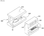
- FIG. 4 is a view illustrating a system provided with the micro robot of the present invention.
- the micro robot system of the present invention includes the micro robot 1, a drive unit 600, and the system control unit 300.
- the micro robot 1 has the same configuration described with reference to FIGS. 1 to 4 , a description will be omitted.
- the drive unit 600 transmits driving power to the micro robot 1 inserted into the human body 30 from the outside of a human body 30 which is a test object.
- the drive unit 600 includes an external drive unit 610, and driving power generated by the external drive unit 610 includes ultrasonic waves, microwaves or an electromagnetic field.
- the external drive unit 610 may be a magnetic field generating unit that generates the external rotational magnetic field.
- the drive unit 600 further includes a position recognition unit 620 which recognizes a position of the micro robot 1 that moves in the human body 30.
- the position recognition unit 620 may recognize the position of the micro robot 1 by capturing x-ray images of the human body 30.
- the system control unit 300 receives position information of the micro robot 1 from the drive unit 600 and controls the drive unit 600.
- system control unit 300 includes a position control unit 310 that treats ultrasonic position information transmitted from the position recognition unit 610 or treats x-ray images transmitted from the position recognition unit 210.
- the position control unit 310 includes a function of treating the x-ray images and recognizing the position of the micro robot 1.
- the system control unit 300 displays the position of the micro robot 1, which is recognized by the position control unit 310, on a display panel 330.
- a practitioner controls the drive unit 600 by operating an operating panel 320 of the system control unit 300, and the micro robot 1 may be moved to a position of a lesion.
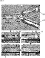
- FIG. 5 is experimental photographs illustrating a state in which the medical micro robot 1 of the present invention is positioned in a blood vessel 10 and removes a thrombus.
- FIG. 5(a) illustrates a state in which the micro robot 1 of the present invention moves in the mock blood vessel 10, discharges a medicine, and creates mechanical drilling motion.
- a mock thrombus 20 including calcium carbonate is installed in the mock blood vessel 10 having a branched tube shape.
- An acetic acid which may chemically react with the calcium carbonate, is accommodated in the micro robot 1.
- the acetic acid is accommodated or received in the medicine accommodating space 130.
- the micro robot 1 of the present invention moves forward with the spiral motion by an external rotational magnetic field of 4mT and 20Hz which satisfies Expression 5, without discharging the medicine to a treatment area in the mock blood vessel 10.
- the micro robot 1 of the present invention After the micro robot 1 of the present invention reaches the treatment area, the micro robot 1 cannot move any further because of the mock thrombus 20.
- the drilling body 100 and the spiral coupling body 200 are spirally coupled by the external rotational magnetic field of 14mT and 20Hz which satisfies Expression 6, and discharge the medicine.
- carbon dioxide bubbles are generated by a chemical reaction between calcium carbonate and carbon dioxide.
- the micro robot 1 which is completely spirally coupled after discharging the acetic acid, that is, the medicine, creates effective drilling motion by the external rotational magnetic field of 4mT and 20Hz that satisfies Expression 7.
- the rearward movement is carried out such that the micro robot returns to an original start position by the external rotational magnetic field of 4mT and 20Hz which rotates in a direction opposite to the direction of the external rotational magnetic field used for the forward movement.
- the micro robot 1 of the present invention may effectively treat a blood vessel.
- the exemplary embodiment according to the present invention may form the spiral coupling structure, perform the forward movement, and drill the thrombus, and may also inject the medicine for dissolving the thrombus.
- the exemplary embodiment according to the present invention may be applied to various diseases of the human body in addition to the treatment of the blood vessel, thereby enabling low-priced and high-efficiency treatment with minimum invasion.
Landscapes
- Health & Medical Sciences (AREA)
- Life Sciences & Earth Sciences (AREA)
- Surgery (AREA)
- Engineering & Computer Science (AREA)
- Animal Behavior & Ethology (AREA)
- General Health & Medical Sciences (AREA)
- Biomedical Technology (AREA)
- Heart & Thoracic Surgery (AREA)
- Veterinary Medicine (AREA)
- Public Health (AREA)
- Molecular Biology (AREA)
- Nuclear Medicine, Radiotherapy & Molecular Imaging (AREA)
- Medical Informatics (AREA)
- Vascular Medicine (AREA)
- Anesthesiology (AREA)
- Hematology (AREA)
- Robotics (AREA)
- Surgical Instruments (AREA)
- Infusion, Injection, And Reservoir Apparatuses (AREA)
- Media Introduction/Drainage Providing Device (AREA)
- Manipulator (AREA)
- Magnetic Treatment Devices (AREA)
- Orthopedic Medicine & Surgery (AREA)
Abstract
Description
- The present invention relates to a medical micro robot, and more particularly, a medical micro robot capable of putting a medicine for dissolving a thrombus into a blood vessel and capable of drilling the thrombus, and a micro robot system having the micro robot.
- In general, a micro robot for a blood vessel treatment may create only mechanical drilling motion in order to treat the blood vessel.
- The blood vessel treatment only using the mechanical drilling motion may be relatively easily implemented because an operating method thereof is simple.
- However, when treating severe blood vessel diseases such as chronic complete stenosis, it is necessary to create relatively high-speed drilling motion, but in this case, there is a great problem in that the high-speed drilling motion may cause secondary damage to a wall of the blood vessel.
- As a traditional method for treating blood vessel diseases, there is a surgical procedure in which a medical practitioner manually inserts a catheter through a femoral artery and manipulates the catheter to open the blood vessel.
- However, because of structural properties of the catheter, the catheter is difficult to be applied to complicated blood vessels, and the success of the surgical procedure is greatly dictated by the skill of the medical practitioner.
- Recently, several advanced research institutes have actively conducted researches regarding micro robots for a blood vessel treatment, as a method for solving the drawback of the catheter.
- The micro robot, which has been developed up to now, is mainly used to treat a clogged blood vessel by using mechanical drilling motion.
- However, in the case of severe blood vessel diseases such as chronic complete stenosis in which the blood vessel is clogged by a hard material, the treatment is difficult to be performed only by the mechanical drilling motion in many instances.
- Meanwhile, a thrombolytic agent is a medicine that may biochemically dissolve the thrombus, and the blood vessel disease may be effectively treated when the thrombolytic agent is used together with the mechanical drilling motion.
- Therefore, it is necessary to develop a micro robot having both of a mechanical drilling motion function and a medicine delivery function in order to improve blood vessel treatment performance of the micro robot.
- As the related art related to the present invention, there is Korean Patent Application Laid-Open No.
10-2009-0122648 (Publication Date: December 1, 2009 - An object of the present invention is to provide a medical micro robot, which may form a spiral coupling structure, perform forward movement, and drill a thrombus, and may also inject a medicine for dissolving the thrombus, and a micro robot system having the micro robot.
- An exemplary embodiment of the present invention provides a micro robot comprising: a drilling body (100) which has a drilling tip (110) formed at an end thereof; and a spiral coupling body (200) which has a magnet disposed therein, and is spirally coupled to an outer circumference of the drilling body (100), and wherein a medicine accommodating space (130), which has a hollow shape and accommodates a medicine, is formed in the drilling body (100).
- A medicine injection hole(120) through which the accommodated medicine is injected to the outside may be formed at the drilling tip(110).
- The spiral coupling body(200) may include: a piston body(210) which is disposed to be fitted into the medicine accommodating space(130) in order to pump the medicine; and a spiral coil(220) which is formed at an end portion of the piston body(210) and spirally coupled to a spiral protrusion(140) formed on the outer circumference of the drilling body (100).
- A magnet slot(230) into which the magnet(400) is fitted and installed may be formed in the piston body(210).
- The magnet slot(230) may be formed as a cylindrical hole and the magnet(400) is formed in a cylindrical bar shape.
- The end portion of the piston body(210) may be formed in a convex shape.
- An exemplary embodiment of the present invention provides a micro robot system comprising; a micro robot(1) which has a drilling body(100) and a spiral coupling body (200); and a system control unit (300) which allows the drilling body (100) and the spiral coupling body(200) to spirally move simultaneously or allows the spiral coupling body (200) to spirally move around the drilling body(100) by providing rotational magnetic field to the magnet, wherein the spiral coupling body (200) has a magnet disposed therein, and is spirally coupled to an outer circumference of the drilling body (100).
- The drilling body(100) may have a drilling tip (110) formed at an end thereof, a medicine accommodating space (130) which has a hollow shape and accommodates a medicine and is formed in the drilling body(100), and a medicine injection hole(120) through which the accommodated medicine is injected to the outside, and formed at an end portion of the drilling tip(110).
- The spiral coupling body(200) may include: a piston body(210) which is disposed to be fitted into the medicine accommodating space(130) in order to pump the medicine; and a spiral coil(220) which is formed at an end portion of the piston body(210) and spirally coupled to a spiral protrusion formed on the outer circumference of the drilling body (100).
- The drilling body(100) and the spiral coupling body(200) spirally may move simultaneously in the forward movement mode and the rearward movement mode, the spiral coupling body(200) spirally moves in a state in which the spiral coupling body(200) is partially and spirally coupled to the outer circumference of the drilling body(100) and the piston body(210) pumps the medicine accommodated in the medicine accommodating space(130) and discharges the medicine through the medicine injection hole in the medicine injection mode, and the drilling body(100) spirally moves in a state in which the spiral coupling body(200) is completely spirally coupled to the outer circumference of the drilling body(100) in the drilling mode.
- The system control unit(300) may control an operation of a magnetic field generating unit that generates the rotational magnetic field, a forward movement mode or a rearward movement mode, a medicine injection mode, a drilling mode are set to the system control unit(300), the system control unit(300) satisfies a condition of


- According to the present invention, the spiral coupling structure may be formed, the forward movement may be performed, the thrombus may be drilled, and the medicine for dissolving the thrombus may be injected.
- In addition, according to the present invention, the micro robot may be applied to various diseases of the human body in addition to the treatment of the blood vessel, thereby enabling low-priced and high-efficiency treatment with minimum invasion.
-
-
FIG. 1 is a coupled perspective view illustrating a medical micro robot of the present invention. -
FIG. 2 is an exploded perspective view illustrating the medical micro robot of the present invention. -
FIG. 3 is a view illustrating torque applied to the medical micro robot of the present invention. -
FIG. 4 is a view illustrating a micro robot system having a medical micro robot of the present invention. -
FIG. 5 is experimental photographs illustrating a state in which the medical micro robot of the present invention is positioned in a blood vessel and removes a thrombus. - Hereinafter, a medical micro robot of the present invention will be described with reference to the accompanying drawings.
-
FIG. 1 is a coupled perspective view illustrating a medical micro robot of the present invention,FIG. 2 is an exploded perspective view illustrating the medical micro robot of the present invention, andFIG. 3 is a view illustrating torque applied to the medical micro robot of the present invention. - A configuration of the medical micro robot of the present invention will be described with reference to
FIGS. 1 and 2 . - A
medical micro robot 1 of the present invention broadly includes adrilling body 100, aspiral coupling body 200, asystem control unit 300. - The
drilling body 100 is formed in a hollow shape, and a diameter at one end or the other end may be gradually decreased. - A
drilling tip 110 is formed at the end of thedrilling body 100. - The
drilling body 100 is formed in a hollow shape, and has a space formed therein. - The space may be a
medicine accommodating space 130 that may receive or accommodate a medicine. - The medicine may be a medicine for dissolving the thrombus formed in a blood vessel, or may be a medicine for various purposes.
- In addition, the
medicine accommodating space 130 provides a space into which apiston body 210 of thespiral coupling body 200, which will be described below, is fitted such that thepiston body 210 may be moved leftward and rightward in themedicine accommodating space 130. - Further, a
medicine injection hole 120, which exposes themedicine accommodating space 130 to the outside and allows the medicine to be injected to the outside, is formed at the end of thedrilling body 100, particularly, at a central portion of thedrilling tip 110. - In addition, a
spiral protrusion 140, which is formed at a predetermined pitch, protrudes from an outer circumference of thedrilling body 100. - The
spiral coupling body 200 includes apiston body 210 and aspiral coil 220. An end of thepiston body 210 is convexly formed. - The
piston body 210 is fitted and disposed into themedicine accommodating space 130 in order to pump the medicine. - One end of the
spiral coil 220 is formed to be fixed to thepiston body 210, and thespiral coil 220 is formed in a spiral shape having a predetermined pitch along the other end. - The
spiral coil 220 may be disposed to be spirally coupled to aspiral groove 150 between threads of thespiral protrusion 140 formed on the outer circumference of thedrilling body 100. - Therefore, the
spiral coupling body 200 may be spirally coupled to thedrilling body 100 so that thespiral coupling body 200 moves forward or rearward at the outer circumference of thedrilling body 100 as thespiral coil 220 is spirally coupled to thespiral groove 150 and moved forward or rearward. - In addition, the
spiral coupling body 200 has amagnet slot 230. - The
magnet slot 230 is formed to have a predetermined depth from one end side of thepiston body 210. - The
magnet slot 230 may be formed to correspond to a shape of a magnet, and for example, themagnet slot 230 may be formed as a cylindrical groove. - Further, a
magnet 400 having a cylindrical bar shape may be fitted, fixed, and installed into themagnet slot 230. - Here, a pitch between the threads of the
spiral protrusion 140 may be greater than a thickness of thespiral coil 220. - Referring to
FIGS. 2 and3 , asystem control unit 300 according to the present invention controls an operation of a magnetic field generating unit (not illustrated) that generates a rotational magnetic field. - With the
magnet 400 inserted into themagnet slot 230, thedrilling body 100 may create x-axis direction spiral motion by an external rotational magnetic field that rotates in an x-axis direction. - In this case, when the
drilling body 100 and thespiral coupling body 200 are partially and spirally coupled to each other, thespiral coupling body 200 and thedrilling body 100 are simultaneously rotated by rotational friction torque between thedrilling body 100 and thespiral coupling body 200, or the motion, which allows thedrilling body 100 and thespiral coupling body 200 to be spirally coupled to each other, may be created. - Magnetic torque applied to the
drilling body 100 in the external magnetic field may be expressed byEquation 1.
- Here,

drilling body 100 by the external magnetic field, m is magnetic moment of the magnet, and B is intensity of the external magnetic field. - Based on
Expression 1, the external rotational magnetic field for creating the spiral motion of themicro robot 1 in the x-axis direction may be expressed by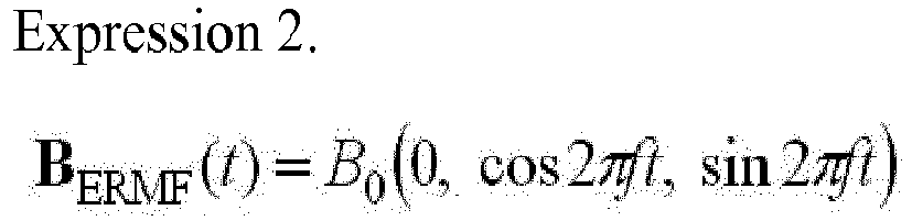
- Here, B 0 is intensity of the external rotational magnetic field, f is a frequency of the external rotational magnetic field, and t is time.
- The proposed rotational motion equation of the
drilling body 100 and thespiral coupling body 200 of themicro robot 1 may be expressed byExpression 3 and Expression 4 as follows.

- Here,

drilling body 100 by the rotational magnetic field.
drilling body 100.
spiral coupling body 200. - I H1 is rotational inertia moment of the
drilling body 100, I H2 is rotational inertia moment of thespiral coupling body 200, and
drilling body 100 and thespiral coupling body 200. - In addition, α H1 is an angular acceleration of the
drilling body 100, and α H2 is an angular acceleration of thespiral coupling body 200. - Referring
Expressions 1 to 4, the magnetic torque applied to thedrilling body 100 is applied within a range of the following Expression 5, thedrilling body 100 and thespiral coupling body 200 simultaneously generates spiral motion by the external rotational magnetic field.
- Here,

drilling body 100 and thespiral coupling body 200. - With the synchronized spiral motion of the
drilling body 100 and thespiral coupling body 200, the partially coupledmicro robot 1 may accommodate the medicine in themedicine accommodating space 130 and may generate forward thrust without a leak of the medicine, and as a result, themicro robot 1 may effectively create movement and steering motion in a fluid environment such as a blood vessel. - When the magnetic torque applied to the
drilling body 100 is applied within a range of the following Expression 6, thedrilling body 100 and thespiral coupling body 200 may be spirally coupled.
- The spiral coupling generates pressure in the
spiral coupling body 200, and the pressure may allow the medicine accommodated in themedicine accommodating space 130 to be injected to the outside through themedicine injection hole 120. - When the completely spirally coupled
micro robot 1 may generate mechanical drilling motion, when themicro robot 1 operates under a condition of Expression 7.
- In summary, a forward movement mode or a rearward movement mode, a medicine injection mode, and a drilling mode are preset to the
system control unit 300 according to the present invention. - The
system control unit 300 satisfies a condition of

- When the drilling mode is carried out, a condition of

- Here,

drilling body 100 by the rotational magnetic field.
drilling body 100 and thespiral coupling body 200.
drilling body 100.
spiral coupling body 200. - I H1 is rotational inertia moment of the
drilling body 100, I H2 is rotational inertia moment of thespiral coupling body 200, and
drilling body 100 and thespiral coupling body 200. - In the forward movement mode and the rearward movement mode, the
drilling body 100 and thespiral coupling body 200 simultaneously perform the spiral motion. In the medicine injection mode, thespiral coupling body 200 performs the spiral motion in a state in which thespiral coupling body 200 is partially and spirally coupled to the outer circumference of thedrilling body 100, and thepiston body 210 pumps the medicine accommodated in themedicine accommodating space 130 so as to inject the medicine to the outside through themedicine injection hole 120. - In the drilling mode, in a state in which the
spiral coupling body 200 is spirally coupled to the outer circumference of thedrilling body 100, thedrilling body 100 performs the spiral motion. -
FIG. 4 is a view illustrating a system provided with the micro robot of the present invention. - Referring to
FIG. 4 , the micro robot system of the present invention includes themicro robot 1, adrive unit 600, and thesystem control unit 300.
Here, themicro robot 1 has the same configuration described with reference toFIGS. 1 to 4 , a description will be omitted. - The
drive unit 600 transmits driving power to themicro robot 1 inserted into thehuman body 30 from the outside of ahuman body 30 which is a test object.
Thedrive unit 600 includes anexternal drive unit 610, and driving power generated by theexternal drive unit 610 includes ultrasonic waves, microwaves or an electromagnetic field. - In particular, the
external drive unit 610 may be a magnetic field generating unit that generates the external rotational magnetic field. - In addition, the
drive unit 600 further includes aposition recognition unit 620 which recognizes a position of themicro robot 1 that moves in thehuman body 30. - In addition, the
position recognition unit 620 may recognize the position of themicro robot 1 by capturing x-ray images of thehuman body 30. - The
system control unit 300 receives position information of themicro robot 1 from thedrive unit 600 and controls thedrive unit 600. - In addition, the
system control unit 300 includes aposition control unit 310 that treats ultrasonic position information transmitted from theposition recognition unit 610 or treats x-ray images transmitted from theposition recognition unit 210. - In addition, the
position control unit 310 includes a function of treating the x-ray images and recognizing the position of themicro robot 1. - The
system control unit 300 displays the position of themicro robot 1, which is recognized by theposition control unit 310, on adisplay panel 330. - A practitioner controls the
drive unit 600 by operating anoperating panel 320 of thesystem control unit 300, and themicro robot 1 may be moved to a position of a lesion. - Next, an experimental example in which a thrombus in a blood vessel is removed and dissolved by using the medical micro robot having the aforementioned configurations will be described.
-
FIG. 5 is experimental photographs illustrating a state in which the medicalmicro robot 1 of the present invention is positioned in ablood vessel 10 and removes a thrombus. -
FIG. 5(a) illustrates a state in which themicro robot 1 of the present invention moves in themock blood vessel 10, discharges a medicine, and creates mechanical drilling motion. - First, a
mock thrombus 20 including calcium carbonate is installed in themock blood vessel 10 having a branched tube shape. - An acetic acid, which may chemically react with the calcium carbonate, is accommodated in the
micro robot 1. The acetic acid is accommodated or received in themedicine accommodating space 130. - First, the
micro robot 1 of the present invention moves forward with the spiral motion by an external rotational magnetic field of 4mT and 20Hz which satisfies Expression 5, without discharging the medicine to a treatment area in themock blood vessel 10. - After the
micro robot 1 of the present invention reaches the treatment area, themicro robot 1 cannot move any further because of themock thrombus 20. - In the
micro robot 1 of the present invention, thedrilling body 100 and thespiral coupling body 200 are spirally coupled by the external rotational magnetic field of 14mT and 20Hz which satisfies Expression 6, and discharge the medicine. - In this case, carbon dioxide bubbles are generated by a chemical reaction between calcium carbonate and carbon dioxide.
- With the generation of the carbon dioxide bubbles, it can be confirmed that a thrombolytic agent accommodated in the
micro robot 1 actually dissolves thethrombus 20. - The
micro robot 1, which is completely spirally coupled after discharging the acetic acid, that is, the medicine, creates effective drilling motion by the external rotational magnetic field of 4mT and 20Hz that satisfies Expression 7. - It takes about 45 seconds to complete the drilling motion.
- Thereafter, the rearward movement is carried out such that the micro robot returns to an original start position by the external rotational magnetic field of 4mT and 20Hz which rotates in a direction opposite to the direction of the external rotational magnetic field used for the forward movement.
- In the experimental example in which the
micro robot 1 of the present invention is used, it takes about 300 seconds to complete the drilling motion of themicro robot 1 actually filled with water. - Therefore, with the assistance of the thrombolytic agent, the
micro robot 1 of the present invention may effectively treat a blood vessel. - With the aforementioned configurations and operations, the exemplary embodiment according to the present invention may form the spiral coupling structure, perform the forward movement, and drill the thrombus, and may also inject the medicine for dissolving the thrombus.
- In addition, the exemplary embodiment according to the present invention may be applied to various diseases of the human body in addition to the treatment of the blood vessel, thereby enabling low-priced and high-efficiency treatment with minimum invasion.
- While the specific exemplary embodiment related with the medical micro robot of the present invention has been described above, the exemplary embodiments may be modified to various exemplary embodiments without departing from the scope of the present invention.
- Therefore, the scope of the present invention should not be limited to the described exemplary embodiment, but should be defined by the appended claims and the equivalents of the claims.
- Accordingly, it should be understood that the aforementioned exemplary embodiment is described for illustration in all aspects and is not limited, and the scope of the present disclosure shall be represented by the claims to be described below, instead of the detailed description, and it should be construed that all of the changes or modified forms induced from the meaning and the scope of the claims, and an equivalent concept thereto are included in the scope of the present disclosure.
Claims (11)
- A micro robot comprising:a drilling body (100) which has a drilling tip (110) formed at an end thereof; anda spiral coupling body (200) which has a magnet disposed therein, and is spirally coupled to an outer circumference of the drilling body (100), andwherein a medicine accommodating space (130), which has a hollow shape and accommodates a medicine, is formed in the drilling body (100).
- The micro robot of claim 1, wherein a medicine injection hole(120) through which the accommodated medicine is injected to the outside is formed at the drilling tip(110).
- The micro robot of claim 1, wherein the spiral coupling body(200) includes:a piston body(210) which is disposed to be fitted into the medicine accommodating space(130) in order to pump the medicine; anda spiral coil(220) which is formed at an end portion of the piston body(210) and spirally coupled to a spiral protrusion(140) formed on the outer circumference of the drilling body (100).
- The micro robot of claim 3, wherein a magnet slot(230) into which the magnet(400) is fitted and installed is formed in the piston body(210).
- The micro robot of claim 4, wherein the magnet slot(230) is formed as a cylindrical hole and the magnet(400) is formed in a cylindrical bar shape.
- The micro robot of claim 3, wherein the end portion of the piston body(210) is formed in a convex shape.
- A micro robot system comprising;
a micro robot(1) which has a drilling body(100) and a spiral coupling body (200); and
a system control unit (300) which allows the drilling body (100) and the spiral coupling body(200) to spirally move simultaneously or allows the spiral coupling body (200) to spirally move around the drilling body(100) by providing rotational magnetic field to the magnet,
wherein the spiral coupling body (200) has a magnet disposed therein, and is spirally coupled to an outer circumference of the drilling body (100). - The micro robot system of claim 7, wherein the drilling body(100) has a drilling tip (110) formed at an end thereof, a medicine accommodating space (130) which has a hollow shape and accommodates a medicine and is formed in the drilling body(100), and a medicine injection hole(120) through which the accommodated medicine is injected to the outside, and formed at the drilling tip(110).
- The micro robot system of claim 8, wherein the spiral coupling body(200) includes:a piston body(210) which is disposed to be fitted into the medicine accommodating space(130) in order to pump the medicine; anda spiral coil(220) which is formed at an end portion of the piston body(210) and spirally coupled to a spiral protrusion formed on the outer circumference of the drilling body (100).
- The micro robot system of claim 9, wherein the drilling body(100) and the spiral coupling body(200) spirally move simultaneously in the forward movement mode and the rearward movement mode, the spiral coupling body(200) spirally moves in a state in which the spiral coupling body(200) is partially and spirally coupled to the outer circumference of the drilling body(100) and the piston body(210) pumps the medicine accommodated in the medicine accommodating space(130) and discharges the medicine through the medicine injection hole in the medicine injection mode, and the drilling body(100) spirally moves in a state in which the spiral coupling body(200) is completely spirally coupled to the outer circumference of the drilling body(100) in the drilling mode.
- The micro robot system of claim 7, wherein the system control unit(300) controls an operation of a magnetic field generating unit that generates the rotational magnetic field, a forward movement mode or a rearward movement mode, a medicine injection mode, a drilling mode are set to the system control unit(300), the system control unit(300) satisfies a condition of


Applications Claiming Priority (3)
| Application Number | Priority Date | Filing Date | Title |
|---|---|---|---|
| KR1020140054104A KR101471526B1 (en) | 2014-05-07 | 2014-05-07 | Medical micro robot and micro robot system having the same |
| PCT/KR2015/000479 WO2015170817A1 (en) | 2014-05-07 | 2015-01-16 | Medical micro-robot and micro-robot system having same |
| EP15788706.8A EP3141199B1 (en) | 2014-05-07 | 2015-01-16 | Medical micro-robot and micro-robot system having same |
Related Parent Applications (2)
| Application Number | Title | Priority Date | Filing Date |
|---|---|---|---|
| EP15788706.8A Division EP3141199B1 (en) | 2014-05-07 | 2015-01-16 | Medical micro-robot and micro-robot system having same |
| EP15788706.8A Division-Into EP3141199B1 (en) | 2014-05-07 | 2015-01-16 | Medical micro-robot and micro-robot system having same |
Publications (3)
| Publication Number | Publication Date |
|---|---|
| EP3494907A2 true EP3494907A2 (en) | 2019-06-12 |
| EP3494907A3 EP3494907A3 (en) | 2019-08-28 |
| EP3494907B1 EP3494907B1 (en) | 2021-05-19 |
Family
ID=52678499
Family Applications (2)
| Application Number | Title | Priority Date | Filing Date |
|---|---|---|---|
| EP15788706.8A Active EP3141199B1 (en) | 2014-05-07 | 2015-01-16 | Medical micro-robot and micro-robot system having same |
| EP19154970.8A Active EP3494907B1 (en) | 2014-05-07 | 2015-01-16 | Medical micro-robot and micro-robot system having the same |
Family Applications Before (1)
| Application Number | Title | Priority Date | Filing Date |
|---|---|---|---|
| EP15788706.8A Active EP3141199B1 (en) | 2014-05-07 | 2015-01-16 | Medical micro-robot and micro-robot system having same |
Country Status (8)
| Country | Link |
|---|---|
| US (1) | US10117991B2 (en) |
| EP (2) | EP3141199B1 (en) |
| KR (1) | KR101471526B1 (en) |
| CN (2) | CN109938806B (en) |
| DK (1) | DK3141199T3 (en) |
| ES (1) | ES2730382T3 (en) |
| TR (1) | TR201907252T4 (en) |
| WO (1) | WO2015170817A1 (en) |
Families Citing this family (31)
| Publication number | Priority date | Publication date | Assignee | Title |
|---|---|---|---|---|
| KR101543708B1 (en) | 2015-01-19 | 2015-08-11 | 한양대학교 산학협력단 | Dual-body magnetic helical robot and magnetic helical robot system comprising the same |
| US9968411B2 (en) | 2015-02-16 | 2018-05-15 | Daegu Gyeongbuk Institute Of Science And Technology | Micro-robot coupled to catheter |
| KR101845941B1 (en) | 2015-02-16 | 2018-04-05 | 재단법인대구경북과학기술원 | Micro robot with intergrated catheter based on ball and socket joint |
| KR102203928B1 (en) * | 2015-03-17 | 2021-01-18 | 한국전자통신연구원 | Method for detecting position of micro robot using ultra wiide band impulse radar and therefore device |
| KR101642022B1 (en) * | 2015-08-03 | 2016-07-22 | 원광대학교산학협력단 | Mobile robot for treatment and control system thereof |
| KR101749586B1 (en) | 2015-12-24 | 2017-06-21 | 재단법인대구경북과학기술원 | Magnetically actuated micro robot based catheter with wireless power transform and it's control method |
| EP3388013A1 (en) * | 2017-04-12 | 2018-10-17 | Max-Planck-Gesellschaft zur Förderung der Wissenschaften e.V. | Propeller and method in which a propeller is set into motion |
| KR101786427B1 (en) * | 2017-06-21 | 2017-10-17 | 한양대학교 산학협력단 | Robot for Drug Delivery |
| KR101818400B1 (en) * | 2017-08-11 | 2018-01-15 | 한양대학교 산학협력단 | Magnetic Robot System |
| KR102066327B1 (en) * | 2017-12-11 | 2020-01-14 | 공주대학교 산학협력단 | A multi-modular helical magnetic millirobot |
| KR102077400B1 (en) | 2018-09-03 | 2020-02-13 | 공주대학교 산학협력단 | Self Prefabricated Ultra compact robot with multiple module structures |
| US10959751B2 (en) * | 2018-11-07 | 2021-03-30 | Warren Z McCarthy | Piezoelectric thrombus removal |
| KR102042938B1 (en) * | 2018-12-31 | 2019-11-11 | 한양대학교 산학협력단 | Tubular cleaning apparatus and method of using the same |
| CN109986570B (en) * | 2019-02-27 | 2021-02-19 | 中国矿业大学 | A spiral conveying robot based on magnetorheological fluid |
| KR102195283B1 (en) * | 2019-04-18 | 2020-12-28 | 공주대학교 산학협력단 | Helical magnetic robot |
| CN112296996B (en) * | 2019-07-26 | 2024-10-01 | 湖南早晨纳米机器人有限公司 | Control method, device and system for motion state of nano robot |
| WO2021020751A1 (en) * | 2019-07-26 | 2021-02-04 | 한양대학교 산학협력단 | Catheter system |
| KR102295728B1 (en) * | 2019-08-28 | 2021-08-31 | 한양대학교 산학협력단 | Micro robot and micro robot system including the robot |
| CN110815169B (en) * | 2019-12-18 | 2025-02-25 | 南方科技大学 | A spiral micro robot and its preparation method and use |
| CN111150436B (en) * | 2020-02-15 | 2023-05-30 | 赵勇 | Spiral propulsion type medical robot |
| CN113197669B (en) * | 2021-05-19 | 2022-03-22 | 广州大学 | Variable-caliber magnetic control internal spiral vascular robot |
| EP4108188A1 (en) * | 2021-06-23 | 2022-12-28 | Artedrone | Medical device, system and method for retrieving a thrombus from a vessel, and method for producing a device |
| KR102665852B1 (en) * | 2021-11-25 | 2024-05-14 | 한양대학교 산학협력단 | Catheter system |
| CN114376671B (en) * | 2022-02-08 | 2024-03-29 | 中国航天科工集团第二研究院 | Low-cost visual bile duct calculus noninvasive lithotripsy and lithotripsy device and method |
| CN114681007B (en) * | 2022-03-24 | 2024-09-13 | 北京理工大学 | Double-helix magnetically controlled microrobot and its processing method and application |
| CN114668505B (en) * | 2022-04-19 | 2025-10-14 | 北京理工大学 | Control system, method, electronic device and medium for magnetically controlled spiral microrobot |
| EP4522055A4 (en) * | 2022-05-08 | 2026-05-06 | Univ Leland Stanford Junior | MAGNETIC MILLISPRIN FOR UNTHEREMIZED ROBOTIC ENDOVASCULAR SURGERY AND METHOD FOR USE |
| CN115944837A (en) * | 2022-07-07 | 2023-04-11 | 哈尔滨工业大学 | A Combined Hierarchical Helical Micro-nano Swimming Robot |
| EP4389051A1 (en) * | 2022-12-22 | 2024-06-26 | Robeaute | Nose dive microrobot |
| KR102680940B1 (en) | 2023-01-05 | 2024-07-02 | 국립공주대학교 산학협력단 | Self-assembly ultra compact robot |
| CN121796796A (en) * | 2026-03-06 | 2026-04-07 | 上海微创医疗机器人(集团)股份有限公司 | Drug-carrying robot and its drive control system |
Citations (1)
| Publication number | Priority date | Publication date | Assignee | Title |
|---|---|---|---|---|
| KR20090122648A (en) | 2008-05-26 | 2009-12-01 | 전남대학교산학협력단 | Micro Robot and Micro Robot System for Vascular Therapy |
Family Cites Families (9)
| Publication number | Priority date | Publication date | Assignee | Title |
|---|---|---|---|---|
| CN101282677B (en) * | 2005-10-05 | 2010-07-28 | 奥林巴斯医疗株式会社 | Capsule medical device, guidance system and guidance method for capsule medical device, and body-insertable apparatus |
| DE102006019985A1 (en) * | 2006-04-26 | 2007-10-31 | Siemens Ag | Orthopedic measures executing device for endoscopic surgery treatment, has part of magnetic body executing periodic translative movement and introducing impact forces on tool e.g. nail, where body is designed as single-piece |
| CN100586361C (en) * | 2008-01-11 | 2010-02-03 | 南京航空航天大学 | Interventional diagnosis and treatment robot and its movement method based on gastropod movement mechanism |
| JP4695678B2 (en) * | 2008-08-04 | 2011-06-08 | オリンパス株式会社 | Capsule medical device |
| KR20100095781A (en) * | 2009-02-23 | 2010-09-01 | 서울대학교산학협력단 | A capsule-type robot with multiple drills for ablating vascular chronic total occlusion |
| KR101092462B1 (en) * | 2009-09-25 | 2011-12-13 | 전남대학교산학협력단 | Drilling Microrobot System Using Rotating Magnetic Field with Precession Motion |
| KR20110052405A (en) * | 2009-11-10 | 2011-05-18 | 김한식 | Spiral propulsion device of capsule endoscope robot |
| KR20110139496A (en) | 2010-06-23 | 2011-12-29 | 서울대학교산학협력단 | Capsule-type Shock Transmitter for Chronic Complete Stenosis Lesion Removal |
| KR20110116968A (en) | 2011-01-31 | 2011-10-26 | 서울대학교산학협력단 | Robot that moves in the tube to remove impurities |
-
2014
- 2014-05-07 KR KR1020140054104A patent/KR101471526B1/en active Active
-
2015
- 2015-01-16 DK DK15788706.8T patent/DK3141199T3/en active
- 2015-01-16 EP EP15788706.8A patent/EP3141199B1/en active Active
- 2015-01-16 TR TR2019/07252T patent/TR201907252T4/en unknown
- 2015-01-16 ES ES15788706T patent/ES2730382T3/en active Active
- 2015-01-16 WO PCT/KR2015/000479 patent/WO2015170817A1/en not_active Ceased
- 2015-01-16 CN CN201910126269.7A patent/CN109938806B/en active Active
- 2015-01-16 US US15/309,265 patent/US10117991B2/en active Active
- 2015-01-16 CN CN201580023958.5A patent/CN106456197B/en active Active
- 2015-01-16 EP EP19154970.8A patent/EP3494907B1/en active Active
Patent Citations (1)
| Publication number | Priority date | Publication date | Assignee | Title |
|---|---|---|---|---|
| KR20090122648A (en) | 2008-05-26 | 2009-12-01 | 전남대학교산학협력단 | Micro Robot and Micro Robot System for Vascular Therapy |
Also Published As
| Publication number | Publication date |
|---|---|
| EP3494907A3 (en) | 2019-08-28 |
| WO2015170817A1 (en) | 2015-11-12 |
| CN109938806B (en) | 2022-05-10 |
| EP3141199B1 (en) | 2019-03-13 |
| CN106456197B (en) | 2019-03-19 |
| EP3494907B1 (en) | 2021-05-19 |
| EP3141199A4 (en) | 2017-12-13 |
| CN109938806A (en) | 2019-06-28 |
| US20170071622A1 (en) | 2017-03-16 |
| KR101471526B1 (en) | 2014-12-12 |
| US10117991B2 (en) | 2018-11-06 |
| CN106456197A (en) | 2017-02-22 |
| EP3141199A1 (en) | 2017-03-15 |
| ES2730382T3 (en) | 2019-11-11 |
| TR201907252T4 (en) | 2019-06-21 |
| DK3141199T3 (en) | 2019-06-11 |
Similar Documents
| Publication | Publication Date | Title |
|---|---|---|
| EP3494907B1 (en) | Medical micro-robot and micro-robot system having the same | |
| US20080065014A1 (en) | Systems, Methods, and Devices to Facilitate Wire and Device Crossings of Obstructions in Body Lumens | |
| US8828001B2 (en) | Bone drill and methods of treatment | |
| AU2015238901B2 (en) | Vascular treatment device | |
| EP2139560B1 (en) | Device for soft tissue destruction | |
| EP3666211A1 (en) | Magnetic robot system | |
| KR101379859B1 (en) | Micro-robot and a system for intravascular therapy | |
| KR102066327B1 (en) | A multi-modular helical magnetic millirobot | |
| EP2196131A1 (en) | Introduction-into-subject system | |
| US20090270850A1 (en) | Devices and methods for the ablation of tissue in the lateral direction | |
| KR101543708B1 (en) | Dual-body magnetic helical robot and magnetic helical robot system comprising the same | |
| EP4487796A1 (en) | Medical water jet scalpel device and medical water jet scalpel system | |
| EP4324517B1 (en) | Ultrasound generation apparatus having adjustable ultrasound focus depth | |
| EP4023175B1 (en) | Microrobot and microrobot system including same | |
| US11607285B2 (en) | Apparatus, system and methodologies for biopsy or removal of tissue or adding material to tissue using a magnetically-actuated capsule | |
| CN109124727B (en) | In-tube longitudinal wave thrombus eliminator | |
| JP6373351B2 (en) | Devices and methods for treating chronic total occlusion | |
| CN111150436B (en) | Spiral propulsion type medical robot | |
| EP4577129A1 (en) | Contrast injection and visualization systems and methods for thrombus removal device | |
| EP4427786A1 (en) | Catheter system | |
| JP2005152093A (en) | Catheter | |
| US10912542B2 (en) | Catheter assembly with offset device for tissue sampling | |
| Hoang et al. | Intestinal tattooing mechanism integrated with active wireless capsule endoscope | |
| EP1935605A1 (en) | Method and apparatus for producing foam | |
| JP2008036026A (en) | Medical equipment device |
Legal Events
| Date | Code | Title | Description |
|---|---|---|---|
| PUAI | Public reference made under article 153(3) epc to a published international application that has entered the european phase |
Free format text: ORIGINAL CODE: 0009012 |
|
| STAA | Information on the status of an ep patent application or granted ep patent |
Free format text: STATUS: THE APPLICATION HAS BEEN PUBLISHED |
|
| AC | Divisional application: reference to earlier application |
Ref document number: 3141199 Country of ref document: EP Kind code of ref document: P |
|
| AK | Designated contracting states |
Kind code of ref document: A2 Designated state(s): AL AT BE BG CH CY CZ DE DK EE ES FI FR GB GR HR HU IE IS IT LI LT LU LV MC MK MT NL NO PL PT RO RS SE SI SK SM TR |
|
| PUAL | Search report despatched |
Free format text: ORIGINAL CODE: 0009013 |
|
| AK | Designated contracting states |
Kind code of ref document: A3 Designated state(s): AL AT BE BG CH CY CZ DE DK EE ES FI FR GB GR HR HU IE IS IT LI LT LU LV MC MK MT NL NO PL PT RO RS SE SI SK SM TR |
|
| RIC1 | Information provided on ipc code assigned before grant |
Ipc: A61M 5/145 20060101ALI20190725BHEP Ipc: A61B 17/00 20060101ALI20190725BHEP Ipc: A61B 90/00 20160101ALI20190725BHEP Ipc: A61M 31/00 20060101ALI20190725BHEP Ipc: A61B 17/22 20060101AFI20190725BHEP Ipc: A61B 34/30 20160101ALI20190725BHEP Ipc: A61B 17/3207 20060101ALI20190725BHEP |
|
| STAA | Information on the status of an ep patent application or granted ep patent |
Free format text: STATUS: REQUEST FOR EXAMINATION WAS MADE |
|
| 17P | Request for examination filed |
Effective date: 20200227 |
|
| RBV | Designated contracting states (corrected) |
Designated state(s): AL AT BE BG CH CY CZ DE DK EE ES FI FR GB GR HR HU IE IS IT LI LT LU LV MC MK MT NL NO PL PT RO RS SE SI SK SM TR |
|
| GRAP | Despatch of communication of intention to grant a patent |
Free format text: ORIGINAL CODE: EPIDOSNIGR1 |
|
| STAA | Information on the status of an ep patent application or granted ep patent |
Free format text: STATUS: GRANT OF PATENT IS INTENDED |
|
| INTG | Intention to grant announced |
Effective date: 20201208 |
|
| GRAS | Grant fee paid |
Free format text: ORIGINAL CODE: EPIDOSNIGR3 |
|
| GRAA | (expected) grant |
Free format text: ORIGINAL CODE: 0009210 |
|
| STAA | Information on the status of an ep patent application or granted ep patent |
Free format text: STATUS: THE PATENT HAS BEEN GRANTED |
|
| AC | Divisional application: reference to earlier application |
Ref document number: 3141199 Country of ref document: EP Kind code of ref document: P |
|
| AK | Designated contracting states |
Kind code of ref document: B1 Designated state(s): AL AT BE BG CH CY CZ DE DK EE ES FI FR GB GR HR HU IE IS IT LI LT LU LV MC MK MT NL NO PL PT RO RS SE SI SK SM TR |
|
| REG | Reference to a national code |
Ref country code: GB Ref legal event code: FG4D |
|
| REG | Reference to a national code |
Ref country code: CH Ref legal event code: EP |
|
| REG | Reference to a national code |
Ref country code: DE Ref legal event code: R096 Ref document number: 602015069615 Country of ref document: DE |
|
| REG | Reference to a national code |
Ref country code: AT Ref legal event code: REF Ref document number: 1393231 Country of ref document: AT Kind code of ref document: T Effective date: 20210615 |
|
| REG | Reference to a national code |
Ref country code: IE Ref legal event code: FG4D |
|
| REG | Reference to a national code |
Ref country code: LT Ref legal event code: MG9D |
|
| REG | Reference to a national code |
Ref country code: AT Ref legal event code: MK05 Ref document number: 1393231 Country of ref document: AT Kind code of ref document: T Effective date: 20210519 |
|
| REG | Reference to a national code |
Ref country code: NL Ref legal event code: MP Effective date: 20210519 |
|
| PG25 | Lapsed in a contracting state [announced via postgrant information from national office to epo] |
Ref country code: BG Free format text: LAPSE BECAUSE OF FAILURE TO SUBMIT A TRANSLATION OF THE DESCRIPTION OR TO PAY THE FEE WITHIN THE PRESCRIBED TIME-LIMIT Effective date: 20210819 Ref country code: AT Free format text: LAPSE BECAUSE OF FAILURE TO SUBMIT A TRANSLATION OF THE DESCRIPTION OR TO PAY THE FEE WITHIN THE PRESCRIBED TIME-LIMIT Effective date: 20210519 Ref country code: FI Free format text: LAPSE BECAUSE OF FAILURE TO SUBMIT A TRANSLATION OF THE DESCRIPTION OR TO PAY THE FEE WITHIN THE PRESCRIBED TIME-LIMIT Effective date: 20210519 Ref country code: HR Free format text: LAPSE BECAUSE OF FAILURE TO SUBMIT A TRANSLATION OF THE DESCRIPTION OR TO PAY THE FEE WITHIN THE PRESCRIBED TIME-LIMIT Effective date: 20210519 Ref country code: LT Free format text: LAPSE BECAUSE OF FAILURE TO SUBMIT A TRANSLATION OF THE DESCRIPTION OR TO PAY THE FEE WITHIN THE PRESCRIBED TIME-LIMIT Effective date: 20210519 |
|
| PG25 | Lapsed in a contracting state [announced via postgrant information from national office to epo] |
Ref country code: SE Free format text: LAPSE BECAUSE OF FAILURE TO SUBMIT A TRANSLATION OF THE DESCRIPTION OR TO PAY THE FEE WITHIN THE PRESCRIBED TIME-LIMIT Effective date: 20210519 Ref country code: PT Free format text: LAPSE BECAUSE OF FAILURE TO SUBMIT A TRANSLATION OF THE DESCRIPTION OR TO PAY THE FEE WITHIN THE PRESCRIBED TIME-LIMIT Effective date: 20210920 Ref country code: RS Free format text: LAPSE BECAUSE OF FAILURE TO SUBMIT A TRANSLATION OF THE DESCRIPTION OR TO PAY THE FEE WITHIN THE PRESCRIBED TIME-LIMIT Effective date: 20210519 Ref country code: NO Free format text: LAPSE BECAUSE OF FAILURE TO SUBMIT A TRANSLATION OF THE DESCRIPTION OR TO PAY THE FEE WITHIN THE PRESCRIBED TIME-LIMIT Effective date: 20210819 Ref country code: LV Free format text: LAPSE BECAUSE OF FAILURE TO SUBMIT A TRANSLATION OF THE DESCRIPTION OR TO PAY THE FEE WITHIN THE PRESCRIBED TIME-LIMIT Effective date: 20210519 Ref country code: PL Free format text: LAPSE BECAUSE OF FAILURE TO SUBMIT A TRANSLATION OF THE DESCRIPTION OR TO PAY THE FEE WITHIN THE PRESCRIBED TIME-LIMIT Effective date: 20210519 Ref country code: GR Free format text: LAPSE BECAUSE OF FAILURE TO SUBMIT A TRANSLATION OF THE DESCRIPTION OR TO PAY THE FEE WITHIN THE PRESCRIBED TIME-LIMIT Effective date: 20210820 Ref country code: IS Free format text: LAPSE BECAUSE OF FAILURE TO SUBMIT A TRANSLATION OF THE DESCRIPTION OR TO PAY THE FEE WITHIN THE PRESCRIBED TIME-LIMIT Effective date: 20210919 |
|
| PG25 | Lapsed in a contracting state [announced via postgrant information from national office to epo] |
Ref country code: NL Free format text: LAPSE BECAUSE OF FAILURE TO SUBMIT A TRANSLATION OF THE DESCRIPTION OR TO PAY THE FEE WITHIN THE PRESCRIBED TIME-LIMIT Effective date: 20210519 |
|
| PG25 | Lapsed in a contracting state [announced via postgrant information from national office to epo] |
Ref country code: SK Free format text: LAPSE BECAUSE OF FAILURE TO SUBMIT A TRANSLATION OF THE DESCRIPTION OR TO PAY THE FEE WITHIN THE PRESCRIBED TIME-LIMIT Effective date: 20210519 Ref country code: ES Free format text: LAPSE BECAUSE OF FAILURE TO SUBMIT A TRANSLATION OF THE DESCRIPTION OR TO PAY THE FEE WITHIN THE PRESCRIBED TIME-LIMIT Effective date: 20210519 Ref country code: EE Free format text: LAPSE BECAUSE OF FAILURE TO SUBMIT A TRANSLATION OF THE DESCRIPTION OR TO PAY THE FEE WITHIN THE PRESCRIBED TIME-LIMIT Effective date: 20210519 Ref country code: SM Free format text: LAPSE BECAUSE OF FAILURE TO SUBMIT A TRANSLATION OF THE DESCRIPTION OR TO PAY THE FEE WITHIN THE PRESCRIBED TIME-LIMIT Effective date: 20210519 Ref country code: RO Free format text: LAPSE BECAUSE OF FAILURE TO SUBMIT A TRANSLATION OF THE DESCRIPTION OR TO PAY THE FEE WITHIN THE PRESCRIBED TIME-LIMIT Effective date: 20210519 Ref country code: DK Free format text: LAPSE BECAUSE OF FAILURE TO SUBMIT A TRANSLATION OF THE DESCRIPTION OR TO PAY THE FEE WITHIN THE PRESCRIBED TIME-LIMIT Effective date: 20210519 Ref country code: CZ Free format text: LAPSE BECAUSE OF FAILURE TO SUBMIT A TRANSLATION OF THE DESCRIPTION OR TO PAY THE FEE WITHIN THE PRESCRIBED TIME-LIMIT Effective date: 20210519 |
|
| REG | Reference to a national code |
Ref country code: DE Ref legal event code: R097 Ref document number: 602015069615 Country of ref document: DE |
|
| PLBE | No opposition filed within time limit |
Free format text: ORIGINAL CODE: 0009261 |
|
| STAA | Information on the status of an ep patent application or granted ep patent |
Free format text: STATUS: NO OPPOSITION FILED WITHIN TIME LIMIT |
|
| 26N | No opposition filed |
Effective date: 20220222 |
|
| PG25 | Lapsed in a contracting state [announced via postgrant information from national office to epo] |
Ref country code: IS Free format text: LAPSE BECAUSE OF FAILURE TO SUBMIT A TRANSLATION OF THE DESCRIPTION OR TO PAY THE FEE WITHIN THE PRESCRIBED TIME-LIMIT Effective date: 20210919 Ref country code: AL Free format text: LAPSE BECAUSE OF FAILURE TO SUBMIT A TRANSLATION OF THE DESCRIPTION OR TO PAY THE FEE WITHIN THE PRESCRIBED TIME-LIMIT Effective date: 20210519 |
|
| PG25 | Lapsed in a contracting state [announced via postgrant information from national office to epo] |
Ref country code: IT Free format text: LAPSE BECAUSE OF FAILURE TO SUBMIT A TRANSLATION OF THE DESCRIPTION OR TO PAY THE FEE WITHIN THE PRESCRIBED TIME-LIMIT Effective date: 20210519 |
|
| PG25 | Lapsed in a contracting state [announced via postgrant information from national office to epo] |
Ref country code: MC Free format text: LAPSE BECAUSE OF FAILURE TO SUBMIT A TRANSLATION OF THE DESCRIPTION OR TO PAY THE FEE WITHIN THE PRESCRIBED TIME-LIMIT Effective date: 20210519 |
|
| REG | Reference to a national code |
Ref country code: CH Ref legal event code: PL |
|
| REG | Reference to a national code |
Ref country code: BE Ref legal event code: MM Effective date: 20220131 |
|
| PG25 | Lapsed in a contracting state [announced via postgrant information from national office to epo] |
Ref country code: LU Free format text: LAPSE BECAUSE OF NON-PAYMENT OF DUE FEES Effective date: 20220116 |
|
| PG25 | Lapsed in a contracting state [announced via postgrant information from national office to epo] |
Ref country code: BE Free format text: LAPSE BECAUSE OF NON-PAYMENT OF DUE FEES Effective date: 20220131 |
|
| PG25 | Lapsed in a contracting state [announced via postgrant information from national office to epo] |
Ref country code: LI Free format text: LAPSE BECAUSE OF NON-PAYMENT OF DUE FEES Effective date: 20220131 Ref country code: CH Free format text: LAPSE BECAUSE OF NON-PAYMENT OF DUE FEES Effective date: 20220131 |
|
| PG25 | Lapsed in a contracting state [announced via postgrant information from national office to epo] |
Ref country code: IE Free format text: LAPSE BECAUSE OF NON-PAYMENT OF DUE FEES Effective date: 20220116 |
|
| PG25 | Lapsed in a contracting state [announced via postgrant information from national office to epo] |
Ref country code: HU Free format text: LAPSE BECAUSE OF FAILURE TO SUBMIT A TRANSLATION OF THE DESCRIPTION OR TO PAY THE FEE WITHIN THE PRESCRIBED TIME-LIMIT; INVALID AB INITIO Effective date: 20150116 |
|
| PG25 | Lapsed in a contracting state [announced via postgrant information from national office to epo] |
Ref country code: MK Free format text: LAPSE BECAUSE OF FAILURE TO SUBMIT A TRANSLATION OF THE DESCRIPTION OR TO PAY THE FEE WITHIN THE PRESCRIBED TIME-LIMIT Effective date: 20210519 Ref country code: CY Free format text: LAPSE BECAUSE OF FAILURE TO SUBMIT A TRANSLATION OF THE DESCRIPTION OR TO PAY THE FEE WITHIN THE PRESCRIBED TIME-LIMIT Effective date: 20210519 |
|
| PG25 | Lapsed in a contracting state [announced via postgrant information from national office to epo] |
Ref country code: MT Free format text: LAPSE BECAUSE OF FAILURE TO SUBMIT A TRANSLATION OF THE DESCRIPTION OR TO PAY THE FEE WITHIN THE PRESCRIBED TIME-LIMIT Effective date: 20210519 |
|
| PG25 | Lapsed in a contracting state [announced via postgrant information from national office to epo] |
Ref country code: TR Free format text: LAPSE BECAUSE OF FAILURE TO SUBMIT A TRANSLATION OF THE DESCRIPTION OR TO PAY THE FEE WITHIN THE PRESCRIBED TIME-LIMIT Effective date: 20210519 |
|
| PGFP | Annual fee paid to national office [announced via postgrant information from national office to epo] |
Ref country code: GB Payment date: 20260108 Year of fee payment: 12 |
|
| PGFP | Annual fee paid to national office [announced via postgrant information from national office to epo] |
Ref country code: DE Payment date: 20260105 Year of fee payment: 12 |
|
| PGFP | Annual fee paid to national office [announced via postgrant information from national office to epo] |
Ref country code: FR Payment date: 20260108 Year of fee payment: 12 |