EP3494889B1 - Method for calibrating an x-ray measuring device - Google Patents
Method for calibrating an x-ray measuring device Download PDFInfo
- Publication number
- EP3494889B1 EP3494889B1 EP17206434.7A EP17206434A EP3494889B1 EP 3494889 B1 EP3494889 B1 EP 3494889B1 EP 17206434 A EP17206434 A EP 17206434A EP 3494889 B1 EP3494889 B1 EP 3494889B1
- Authority
- EP
- European Patent Office
- Prior art keywords
- energy
- ray
- interval
- absorption function
- test object
- Prior art date
- Legal status (The legal status is an assumption and is not a legal conclusion. Google has not performed a legal analysis and makes no representation as to the accuracy of the status listed.)
- Active
Links
- 238000000034 method Methods 0.000 title claims description 25
- 238000010521 absorption reaction Methods 0.000 claims description 84
- 238000012360 testing method Methods 0.000 claims description 53
- 238000005259 measurement Methods 0.000 claims description 36
- 238000012937 correction Methods 0.000 claims description 28
- 230000003595 spectral effect Effects 0.000 claims description 12
- 238000001228 spectrum Methods 0.000 claims description 11
- 238000003384 imaging method Methods 0.000 claims description 7
- 238000002591 computed tomography Methods 0.000 claims 1
- 239000000463 material Substances 0.000 description 10
- 238000002083 X-ray spectrum Methods 0.000 description 6
- 238000002360 preparation method Methods 0.000 description 6
- 230000005855 radiation Effects 0.000 description 6
- 238000010586 diagram Methods 0.000 description 5
- 230000000694 effects Effects 0.000 description 5
- 230000001419 dependent effect Effects 0.000 description 4
- 238000001514 detection method Methods 0.000 description 4
- 239000010405 anode material Substances 0.000 description 2
- 238000001914 filtration Methods 0.000 description 2
- 238000009499 grossing Methods 0.000 description 2
- 238000012545 processing Methods 0.000 description 2
- XLYOFNOQVPJJNP-UHFFFAOYSA-N water Substances O XLYOFNOQVPJJNP-UHFFFAOYSA-N 0.000 description 2
- 230000001133 acceleration Effects 0.000 description 1
- 238000013459 approach Methods 0.000 description 1
- 230000005540 biological transmission Effects 0.000 description 1
- 238000004364 calculation method Methods 0.000 description 1
- 239000013078 crystal Substances 0.000 description 1
- 238000011161 development Methods 0.000 description 1
- 230000018109 developmental process Effects 0.000 description 1
- 238000012423 maintenance Methods 0.000 description 1
- 238000010606 normalization Methods 0.000 description 1
- 230000003287 optical effect Effects 0.000 description 1
- 230000035515 penetration Effects 0.000 description 1
- 230000000737 periodic effect Effects 0.000 description 1
- 230000003334 potential effect Effects 0.000 description 1
- 230000000644 propagated effect Effects 0.000 description 1
- 230000002441 reversible effect Effects 0.000 description 1
- 239000004065 semiconductor Substances 0.000 description 1
- 238000007619 statistical method Methods 0.000 description 1
- 230000001360 synchronised effect Effects 0.000 description 1
- 238000012546 transfer Methods 0.000 description 1
- 230000009466 transformation Effects 0.000 description 1
- 230000004304 visual acuity Effects 0.000 description 1
- 230000003313 weakening effect Effects 0.000 description 1
Images


Classifications
-
- A—HUMAN NECESSITIES
- A61—MEDICAL OR VETERINARY SCIENCE; HYGIENE
- A61B—DIAGNOSIS; SURGERY; IDENTIFICATION
- A61B6/00—Apparatus for radiation diagnosis, e.g. combined with radiation therapy equipment
- A61B6/58—Testing, adjusting or calibrating apparatus or devices for radiation diagnosis
- A61B6/582—Calibration
- A61B6/583—Calibration using calibration phantoms
- A61B6/584—Calibration using calibration phantoms determining position of components of the apparatus or device using images of the phantom
-
- A—HUMAN NECESSITIES
- A61—MEDICAL OR VETERINARY SCIENCE; HYGIENE
- A61B—DIAGNOSIS; SURGERY; IDENTIFICATION
- A61B6/00—Apparatus for radiation diagnosis, e.g. combined with radiation therapy equipment
- A61B6/02—Devices for diagnosis sequentially in different planes; Stereoscopic radiation diagnosis
- A61B6/03—Computerised tomographs
- A61B6/032—Transmission computed tomography [CT]
-
- A—HUMAN NECESSITIES
- A61—MEDICAL OR VETERINARY SCIENCE; HYGIENE
- A61B—DIAGNOSIS; SURGERY; IDENTIFICATION
- A61B6/00—Apparatus for radiation diagnosis, e.g. combined with radiation therapy equipment
- A61B6/42—Apparatus for radiation diagnosis, e.g. combined with radiation therapy equipment with arrangements for detecting radiation specially adapted for radiation diagnosis
- A61B6/4208—Apparatus for radiation diagnosis, e.g. combined with radiation therapy equipment with arrangements for detecting radiation specially adapted for radiation diagnosis characterised by using a particular type of detector
- A61B6/4241—Apparatus for radiation diagnosis, e.g. combined with radiation therapy equipment with arrangements for detecting radiation specially adapted for radiation diagnosis characterised by using a particular type of detector using energy resolving detectors, e.g. photon counting
-
- A—HUMAN NECESSITIES
- A61—MEDICAL OR VETERINARY SCIENCE; HYGIENE
- A61B—DIAGNOSIS; SURGERY; IDENTIFICATION
- A61B6/00—Apparatus for radiation diagnosis, e.g. combined with radiation therapy equipment
- A61B6/48—Diagnostic techniques
- A61B6/482—Diagnostic techniques involving multiple energy imaging
-
- A—HUMAN NECESSITIES
- A61—MEDICAL OR VETERINARY SCIENCE; HYGIENE
- A61B—DIAGNOSIS; SURGERY; IDENTIFICATION
- A61B6/00—Apparatus for radiation diagnosis, e.g. combined with radiation therapy equipment
- A61B6/58—Testing, adjusting or calibrating apparatus or devices for radiation diagnosis
- A61B6/582—Calibration
- A61B6/583—Calibration using calibration phantoms
-
- A—HUMAN NECESSITIES
- A61—MEDICAL OR VETERINARY SCIENCE; HYGIENE
- A61B—DIAGNOSIS; SURGERY; IDENTIFICATION
- A61B6/00—Apparatus for radiation diagnosis, e.g. combined with radiation therapy equipment
- A61B6/58—Testing, adjusting or calibrating apparatus or devices for radiation diagnosis
- A61B6/582—Calibration
- A61B6/585—Calibration of detector units
-
- G—PHYSICS
- G01—MEASURING; TESTING
- G01N—INVESTIGATING OR ANALYSING MATERIALS BY DETERMINING THEIR CHEMICAL OR PHYSICAL PROPERTIES
- G01N23/00—Investigating or analysing materials by the use of wave or particle radiation, e.g. X-rays or neutrons, not covered by groups G01N3/00 – G01N17/00, G01N21/00 or G01N22/00
- G01N23/02—Investigating or analysing materials by the use of wave or particle radiation, e.g. X-rays or neutrons, not covered by groups G01N3/00 – G01N17/00, G01N21/00 or G01N22/00 by transmitting the radiation through the material
- G01N23/04—Investigating or analysing materials by the use of wave or particle radiation, e.g. X-rays or neutrons, not covered by groups G01N3/00 – G01N17/00, G01N21/00 or G01N22/00 by transmitting the radiation through the material and forming images of the material
- G01N23/046—Investigating or analysing materials by the use of wave or particle radiation, e.g. X-rays or neutrons, not covered by groups G01N3/00 – G01N17/00, G01N21/00 or G01N22/00 by transmitting the radiation through the material and forming images of the material using tomography, e.g. computed tomography [CT]
-
- G—PHYSICS
- G01—MEASURING; TESTING
- G01T—MEASUREMENT OF NUCLEAR OR X-RADIATION
- G01T1/00—Measuring X-radiation, gamma radiation, corpuscular radiation, or cosmic radiation
- G01T1/29—Measurement performed on radiation beams, e.g. position or section of the beam; Measurement of spatial distribution of radiation
- G01T1/2914—Measurement of spatial distribution of radiation
- G01T1/2985—In depth localisation, e.g. using positron emitters; Tomographic imaging (longitudinal and transverse section imaging; apparatus for radiation diagnosis sequentially in different planes, steroscopic radiation diagnosis)
-
- G—PHYSICS
- G01—MEASURING; TESTING
- G01N—INVESTIGATING OR ANALYSING MATERIALS BY DETERMINING THEIR CHEMICAL OR PHYSICAL PROPERTIES
- G01N2223/00—Investigating materials by wave or particle radiation
- G01N2223/30—Accessories, mechanical or electrical features
- G01N2223/303—Accessories, mechanical or electrical features calibrating, standardising
- G01N2223/3035—Accessories, mechanical or electrical features calibrating, standardising phantom
-
- G—PHYSICS
- G01—MEASURING; TESTING
- G01N—INVESTIGATING OR ANALYSING MATERIALS BY DETERMINING THEIR CHEMICAL OR PHYSICAL PROPERTIES
- G01N2223/00—Investigating materials by wave or particle radiation
- G01N2223/40—Imaging
- G01N2223/423—Imaging multispectral imaging-multiple energy imaging
-
- G—PHYSICS
- G01—MEASURING; TESTING
- G01T—MEASUREMENT OF NUCLEAR OR X-RADIATION
- G01T7/00—Details of radiation-measuring instruments
- G01T7/005—Details of radiation-measuring instruments calibration techniques
Definitions
- the invention relates to a method for calibrating an X-ray measuring device, which comprises a spectrally sensitive X-ray detector, wherein a test object is positioned in the beam path of an X-ray beam, the test object is irradiated by the X-ray beam, and an intensity measurement of the test object is carried out by means of the X-ray measuring device, and from the intensity measurement of the test object, an absorption function of the test object is determined, a correction function of the absorption function being determined, and the X-ray measuring device being calibrated using the correction function.
- a computer tomograph In a computer tomograph (CT), various absorption profiles of the body tissue to be examined are recorded by means of X-rays, which are emitted on the patient's body from different angular directions, and a volume model of the body tissue is reconstructed on the basis of these absorption profiles and knowledge of the beam path used.
- CT computer tomograph
- X-rays X-rays
- a volume model of the body tissue is reconstructed on the basis of these absorption profiles and knowledge of the beam path used.
- a calibration of the X-ray measuring device of the CT is carried out in order to be able to generally correct errors in the image, which can occur due to the measuring apparatus or due to the measuring principle used.
- the beam hardening is based on the physical principle that the absorption is energy-dependent, as a result of which, in the X-ray spectrum, higher-energy photons absorb human tissue or material with similar optical properties to a lesser extent are called lower energy x-ray photons.
- the X-ray spectrum incident on the X-ray detector therefore has a transmitted spectrum with a higher mean value of energy than the input spectrum due to the stronger absorption of the low-energy components.
- the invention is based on the object of specifying a method for calibrating an X-ray measuring device which is suitable for correcting the potential effects of beam hardening on the measurement results of the X-ray measuring device with as little effort as possible.
- the stated object is achieved according to the invention by a method for calibrating an X-ray measuring device, which comprises a spectrally sensitive X-ray detector, the X-ray measuring device for a measurement for a resolution a plurality of different energy intervals is prepared in such a way that the x-ray detector divides energy from incident x-ray photons of an x-ray beam into the individual energy intervals, a test object is positioned in the beam path of the x-ray beam, the test object by the x-ray beam, in particular from different angles and is irradiated in different positions, and an intensity measurement of the test object that is resolved according to the energy intervals is carried out by means of the X-ray measuring device, and an absorption function of the test object is determined on the basis of the intensity measurement of the test object.
- one of the energy intervals is selected as a reference interval or is prepared in such a way that the absorption function has a negligible energy dependency over the relevant energy interval, and that the relevant energy interval is selected as a reference interval is that a correction function of the absorption function for at least one further energy interval is determined on the basis of at least one value of the absorption function in the reference interval, and that the X-ray measuring device is calibrated using the correction function.
- the X-ray measuring device is arranged in a CT, or is provided for the intended operation in a CT and set up accordingly.
- the preparation of the x-ray measuring device for a measurement for a resolution of a plurality of different energy intervals includes, in particular, measures being taken which make it possible, by means of the x-ray measuring device, for a resultant intensity profile with the corresponding energy resolution when the test body is irradiated once by the x-ray beam to be able to register, and thus preferably to obtain an individual intensity profile for each energy interval of the X-radiation individually.
- the intensity measurement correspondingly resolved according to the energy intervals is implemented as such a measurement, in which a separate, preferably spatially resolved intensity profile is thus generated for each energy interval of the X-rays.
- test object here includes in particular a body with known geometric dimensions and with known material properties in its interior with regard to the type and the spatial distribution, which preferably has a certain geometric regularity and in particular a convexity.
- the X-ray measuring device is preferably used to carry out a reference intensity measurement of the X-ray beam that is correspondingly resolved according to the energy intervals, the absorption function of the test object being additionally determined on the basis of the reference intensity measurement of the X-ray beam.
- the maximum intensity I 0 which is achieved when the X-ray beam irradiates the X-ray measuring device without any absorbing objects in its beam path is particularly preferably measured here.
- I 0 is therefore the reference intensity with regard to air.
- the preparation of the relevant energy interval as a reference interval can take place in particular on the basis of theoretical knowledge and considerations with regard to the absorption function a 'to be expected in a measurement.
- an absorption function a + for the test body or for a comparison test body, which has similar geometrical and material properties, and for the test body an absorption function a 'to be expected from a measurement which corresponds to the measurements in the The method is comparable can be determined on the basis of a transfer of the measurement results obtained and the knowledge obtained from them to the test body.
- the range of values in (E) as a function of energy E can now be determined on the one hand, so that a reduced range of values in R (E) can be determined from this, which has a negligible energy dependency for the corresponding energy of represents incident photons, so for example da '/ dE ⁇ 0 for E out in R (E) applies.
- the corresponding energy range ⁇ E R can be determined in the energy space for which the absorption function a 'to be expected takes on values in this reduced range of values in R (E).
- the energy dependency of the absorption function a 'to be expected is thus negligible over the energy range ⁇ E R thus determined within the scope of the existing magnitudes, which are given by the value range in (E).
- the behavior determined on the basis of the expected absorption function a ' is now transferred to the real measurements in the method, and the determined energy range ⁇ E R is in particular prepared as the reference interval.
- Determining a correction function of the absorption function for at least one further energy interval on the basis of at least one value of the absorption function in the reference interval means in particular that at least one value of the absorption function is determined which corresponds to an energy of the incident X-ray photon in the reference interval corresponds. A plurality of such values is preferably determined. On the basis of this or these values, a correction function of the absorption function a is then determined as a function of the same for the entire energy range, by means of which the measured values of the absorption function a are to be corrected, in particular outside the reference interval in R (E).
- the total of the values of the absorption function a ( ⁇ E R ) for the reference interval ⁇ E R corresponds to an essentially monochromatic X-ray beam, even if the spectral is real
- the width of the incident X-ray radiation is still finite, since this takes place in a frequency or energy range in which the finiteness of the spectral width has no significant effects on the absorption function a.
- this relationship is preferably adequately taken into account for monochromatic X-ray photons, such as, for example, that given above via the logarithm of the intensities, so that in this case the absorption function a is linearly dependent on the thickness.
- the correction function can be determined in such a way that for each spatial resolution pixel of the X-ray measuring device, the measured intensities for different measurements of the test body, preferably with different thicknesses of the irradiated material of the test body, are entered in a so-called scatter plot, in which e.g. the abscissa value is the measured absorption function a, while the ordinate value is given by the absorption function A assumed for the corresponding thickness for a monochromatic X-ray beam (not to be confused with the expected absorption function a 'when determining the monotonic behavior of the absorption function a).
- a correction function of the absorption function a can be determined in dependence thereon in such a way that the corrected absorption function A (a) corresponds to that which would be obtained for monochromatic X-ray photons.
- the correction function can be determined from the points or pairs of values mentioned in the scatter plot using methods known in statistical data processing, e.g. using polynomial smoothing.
- the X-ray measuring device can now be calibrated in such a way that effects of the beam hardening are corrected, and in particular the Hounsfield scale for standardization can be adhered to without restriction.
- a broadband energy interval is prepared as a reference interval, the lower limit of which is at least the value of 60%, preferably at least 2/3 of the maximum energy of the spectrum of the X-ray beam, and the spectral width of which is preferably at least 1/5. is particularly preferably at least 1/4 of the maximum energy of the spectrum of the X-ray beam.
- the maximum energy of the spectrum of the X-ray beam is in particular limited by the acceleration voltage of the anode of the X-ray tube that generates the X-ray radiation.
- An energy interval intended for the energy-resolved normal operation of the X-ray measuring device is advantageously selected as the reference interval. This has the advantage that the preparation of the individual energy intervals for the measurements to determine the correction function can be carried out immediately in the context of a preparation for commissioning.
- a narrow-band energy interval is used as the reference interval prepared, the spectral width is at most 1/8, preferably at most 1/10 of the maximum energy of the spectrum of the X-ray beam.
- a corresponding energy interval is prepared as a reference interval especially for the measurements to determine the correction function, by means of which the correction function for the other energy intervals, as are provided for the energy-resolved normal operation of the X-ray measuring device, for the corresponding calibration be determined. Measurements are preferably carried out at several reference intervals of comparable spectral width and different positioning in the energy range in order to obtain particularly good energy resolution and high precision in the energy space for the entire X-ray spectrum.
- the preparation of the reference interval is expediently canceled for the energy-resolved normal operation of the X-ray measuring device. That is, after the measurements for determining the correction function and a corresponding calibration of the individual energy intervals of the X-ray measuring device for energy-resolved normal operation, the reference interval is no longer found in the configuration of the energy intervals.
- values of the absorption function for the reference interval are plotted against values of the absorption function for the at least one further energy interval, and from this the absorption function for the reference interval as a function of the absorption function A (a) for the at least one further energy interval is determined as a correction function in the relevant energy interval.
- This is particularly easy to do Establish a functional connection between the measurements actually determined by the X-ray measuring device in the various energy intervals and a hypothetical measurement for monochromatic X-ray radiation, and then use this functional connection for the correction.
- the X-ray measuring device performs a rotational movement with respect to the test object for the intensity measurement of the test object.
- the radiation source of the x-ray beam also performs a rotation, and preferably both rotations are synchronized with one another in such a way that the x-ray measuring device and x-ray beam source do not move relative to one another.
- the path length, which the X-ray beam propagates through the test object is varied by the rotation.
- a quantum-counting X-ray detector is advantageously calibrated as the X-ray measuring device.
- Such an X-ray detector allows energy-resolved detection of X-ray photons at a high spatial resolution, but for the correct normalization of the counting events with respect to the reference intensity I 0 without an object in the beam path, a complex calibration is necessary, for which the proposed method is particularly well suited.
- the reference interval is prepared via at least one voltage level in a signal amplifier of the X-ray measuring device.
- the spatially resolved detection of X-ray photons can be done in different ways. One possibility is to generally convert the energy of the incident X-ray photons into electrical charges and further into current or voltage signals by ionizing atoms in a crystal provided for this purpose, for example a semiconductor. The amplitude of the corresponding current or voltage signal is preferably proportional to the energy of an incident X-ray photon.
- the filtering in the detector according to individual energy ranges can then take place on the basis of the voltage levels mentioned, for example in the sense of "bias voltages" against which the generated current or voltage signal has to run, so that those signals from X-ray photons of a lower energy than that of the selected bias voltage does not overcome the bias voltage, and thus the signal is not registered accordingly.
- the energy range can thus be divided into a plurality of intervals over a plurality of voltage stages.
- the invention further specifies an imaging medical device with at least one x-ray source for generating an x-ray beam and an x-ray measuring device, which is set up to calibrate the x-ray measuring device according to the method described above.
- the advantages specified for the calibration method and for its further developments can be applied analogously to the imaging medical device.
- the described method is particularly advantageous for an imaging medical device in which a spectrally sensitive X-ray detector is used for 3D reconstruction.
- the imaging medical device can accordingly be configured in particular as a CT, but also as a C-arm device.
- FIG. 1 a CT 1 is shown schematically in a cross-sectional illustration, which has a rotating ring 2 and a holding frame 4.
- An x-ray source 6 for generating an x-ray beam 8 and an x-ray measuring device 10, which is designed as a quantum-counting x-ray detector 12, are arranged on the turntable 2.
- the turntable 2 now rotates about an axis 13 perpendicular to the image plane, a patient positioned in the inside of the turntable 2 being penetrated by the X-ray beam 8 from different angular directions, so that the X-ray detector 12 provides a two-dimensional absorption profile for each of these angular directions X-ray radiation is generated, which is transmitted to an image processing unit, not shown, on the holding frame 4. From the entirety of the absorption profiles generated in all angular directions, a three-dimensional volume model of the patient tissue examined in the CT is then generated via a reverse transformation.
- the individual absorption profiles have to be corrected with regard to the beam hardening, so that the actually determined absorption does not contain any distortions caused by the thickness of the absorbing tissue for an angular direction.
- calibration measurements of the absorption profiles of a plurality of test objects of known geometry and material properties are usually carried out in order to obtain additional information regarding an expected absorption distribution for an angular direction based on the knowledge of the thickness of the irradiated test object.
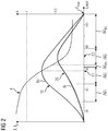
- FIG 2 are schematic in a diagram against the energy E of the incident X-ray photons, the intensity I 0 of an X-ray beam 8o without filtering by a test object and the intensity I by a test object 16
- FIG. 1 partially absorbed X-ray beam 8t for a pixel of the X-ray detector 12.
- the values for the individual energies largely depend on the anode material used for the X-ray source. For the sake of clarity, the spectral contributions of the line spectrum characteristic of the anode material have been omitted.
- the intensity I 0 of the unfiltered X-ray beam 8o initially has a monotonic increase 18 in the energy E in order to reach its maximum at an energy E 1 of just over 55 keV and then to drop monotonically. Due to the higher absorption at lower energies, the intensity I of the X-ray beam 8t filtered by the test object 16 initially has a much flatter rise 20 in order to then assume the maximum at a value E 2 of approximately 70 keV.
- the diagram of FIG 2 clearly that the essential contributions of the intensity I for the x-ray beam 8t generally depend on the intensity I 0 of the X-ray beam 8o are shifted towards higher energies.
- FIG. 2 the energy-resolved detection indicated by the X-ray detector 12 FIG. 1 is recorded and passed on.
- the X-ray detector divides the energy E into individual energy intervals ⁇ E j . All x-ray photons, the energy of which lies in such an energy interval ⁇ E j , consequently have the same energy for the x-ray detector 12 within the scope of its energy resolving power, which is exactly given by the energy intervals ⁇ E j .
- the intensities I, I 0 are then only recorded as blocks I ( ⁇ E j ), I 0 ( ⁇ E j ), which are not shown here.
- An absorption function a: -log (I / I 0 ), drawn in as a dashed line with scaling on the right axis - now obviously has a corresponding energy dependency due to the energy dependence of the intensities I, I 0 involved. Due to the rough division of the energy into individual intervals ⁇ E j , the correct detection of the energy dependency in the absorption function a would be lost, provided that this energy dependence of the absorption function a, as is the case here for the calibration of the X-ray detector 12, is important and cannot be neglected.
- an energy interval ⁇ E R1 is chosen to be so narrow - in the present case from 60 to 62 keV - that the absorption function a over the said energy interval ⁇ E R1 only by approximately 0.05 with a value range from approximately 0.2 to about 1.2, so hardly noticeable changes.
- the x-ray beam 8 is essentially monochromatic with regard to the behavior of the absorption function a, so that it can be used as a reference interval for measurements in which knowledge of the absorption function for a monochromatic x-ray beam is desired.
- the energy interval ⁇ E R1 can also be chosen to be wider, the choice depending on the behavior of the absorption function a.
- the reference interval ⁇ E R1 over the range of approximately 70-80 keV can also be selected with a spectral width of approximately 10-11 keV since there the absorption function a changes its values only insignificantly compared to the entire range of values.
- the energy interval ⁇ E R2 has a not insignificant spectral width of several ten keV, however, due to the behavior of the two intensities I, I 0 during the course of the absorption function a, this spectral width is not significant, which is why the energy interval ⁇ E R2 can be used as a reference interval.
- FIG 3 the sequence of a method for calibrating the X-ray detector 12 of the CT 1 is shown schematically using a block diagram FIG. 1 shown.
- a reference measurement of the intensity I 0 of the X-ray beam 8o which is only filtered by the air in the interior of the CT, is carried out.
- the test object 16 is positioned in the beam path 14 of the X-ray beam 8.
- the test object is preferably to be mounted eccentrically, so that x-rays 8t generated at different angular directions have to cover a different path length through the test object 16, which can be taken into account when calculating the correction function.
- an energy interval ⁇ E j is prepared as a reference interval ⁇ E R1 by setting corresponding voltage levels in the preamplification for the generated signals. In the present case, a narrow-band energy interval is selected.
- a measurement of the intensity I of the x-ray beam 8t transmitted by the test object 16 is carried out in a location-resolved manner and carried out in an energy-resolved manner in accordance with the prepared energy intervals including the reference interval ⁇ E R1 . From the reference intensity I 0 and the intensity I transmitted by the test object 16, values of an absorption function a are now calculated in a step S5 for each energy interval ⁇ E j to be calibrated.
- the values of the absorption function A are calculated for the reference interval ⁇ E R1 .
- a scatter plot is made for each energy interval ⁇ E j and each pixel of the X-ray detector 12, the values a of the measured absorption function being plotted on the abscissa axis in the energy interval ⁇ E j to be calibrated, and the values A of the reference interval ⁇ E R1 on the ordinate axis.
- a function A (a) is determined from the values of the set of points, which gives the correction function for the relevant pixel for correcting the beam hardening in the corresponding energy interval ⁇ E j , and thereby calibrates the X-ray detector.
Description
Die Erfindung betrifft ein Verfahren zur Kalibrierung einer Röntgenmesseinrichtung, welche einen spektralsensitiven Röntgendetektor umfasst, wobei ein Testobjekt im Strahlengang eines Röntgenstrahls positioniert wird, das Testobjekt durch den Röntgenstrahl bestrahlt wird, und dabei mittels der Röntgenmesseinrichtung eine Intensitätsmessung des Testobjekts durchgeführt wird, und aus der Intensitätsmessung des Testobjekts eine Absorptionsfunktion des Testobjektes ermittelt wird, wobei eine Korrekturfunktion der Absorptionsfunktion ermittelt wird, und die Röntgenmesseinrichtung anhand der Korrekturfunktion kalibriert wird.The invention relates to a method for calibrating an X-ray measuring device, which comprises a spectrally sensitive X-ray detector, wherein a test object is positioned in the beam path of an X-ray beam, the test object is irradiated by the X-ray beam, and an intensity measurement of the test object is carried out by means of the X-ray measuring device, and from the intensity measurement of the test object, an absorption function of the test object is determined, a correction function of the absorption function being determined, and the X-ray measuring device being calibrated using the correction function.
In einem Computertomographen (CT) werden mittels Röntgenstrahlen, welche aus verschiedenen Winkelrichtungen um einen Patientenkörper herum auf diesen ausgesandt werden, verschiedene Absorptionsprofile des zu untersuchenden Körpergewebes aufgenommen, und anhand dieser Absorptionsprofile und der Kenntnis des verwendeten Strahlengangs ein Volumenmodell des Körpergewebes rekonstruiert. Vor einer Inbetriebnahme des CT, oder auch in periodischen Zeitabständen, wie z.B. bei turnusgemäßen Wartungen, wird eine Kalibrierung der Röntgenmesseinrichtung des CT durchgeführt, um allgemein Fehler in der Abbildung korrigieren zu können, welche aufgrund der Messapparatur oder aufgrund des verwendeten Messprinzips auftreten können.In a computer tomograph (CT), various absorption profiles of the body tissue to be examined are recorded by means of X-rays, which are emitted on the patient's body from different angular directions, and a volume model of the body tissue is reconstructed on the basis of these absorption profiles and knowledge of the beam path used. Before commissioning the CT, or also at periodic intervals, e.g. with regular maintenance, a calibration of the X-ray measuring device of the CT is carried out in order to be able to generally correct errors in the image, which can occur due to the measuring apparatus or due to the measuring principle used.
Einer der bei der Kalibrierung zu berücksichtigenden Effekte ist die unter Verwendung polychromatischer Röntgenspektren auftretende sog. Strahlaufhärtung, welche zu Bildartefakten führen kann (sog. "Cupping-Artefakte"). Der Strahlaufhärtung liegt das physikalische Prinzip zugrunde, dass die Absorption energieabhängig ist, wodurch im Röntgenspektrum höherenergetische Photonen von menschlichem Gewebe oder Material mit ähnlichen optischen Eigenschaften in geringerem Maß absorbiert werden als Röntgenphotonen niedrigerer Energie. Bei der Propagation der Röntgenstrahlung durch ein Objekt wie einen Testkörper aus Wasser oder durch einen menschlichen Körper weist daher das am Röntgendetektor auftreffende Röntgenspektrum infolge der stärkeren Absorption der niederenergetischen Komponenten ein transmittiertes Spektrum mit einem höheren Mittelwert der Energie auf als das Eingangsspektrum.One of the effects to be taken into account in the calibration is the so-called beam hardening that occurs using polychromatic X-ray spectra, which can lead to image artifacts (so-called "cupping artifacts"). The beam hardening is based on the physical principle that the absorption is energy-dependent, as a result of which, in the X-ray spectrum, higher-energy photons absorb human tissue or material with similar optical properties to a lesser extent are called lower energy x-ray photons. When the X-ray radiation is propagated by an object such as a test body made of water or by a human body, the X-ray spectrum incident on the X-ray detector therefore has a transmitted spectrum with a higher mean value of energy than the input spectrum due to the stronger absorption of the low-energy components.
Diese Strahlaufhärtung kann nun zu einer Verfälschung der Absorptionsprofile in Abhängigkeit der Dicke des im jeweiligen Absorptionsprofil untersuchten Körpergewebes führen. Insbesondere kann dabei ein Volumenelement des Materials im Inneren eines größeren Objektes einen scheinbar geringeren Absorptionskoeffizienten aufweisen, als ein vergleichbares Volumenelement an der Oberfläche des Objekts. Bei der dreidimensionalen Rekonstruktion können infolgedessen Artefakte auftreten, in welchen insbesondere ein homogenes Objekt durch den CT als inhomogen dargestellt werden kann.This beam hardening can now lead to a falsification of the absorption profiles depending on the thickness of the body tissue examined in the respective absorption profile. In particular, a volume element of the material inside a larger object can have an apparently lower absorption coefficient than a comparable volume element on the surface of the object. As a result, artefacts can occur in the three-dimensional reconstruction, in which, in particular, a homogeneous object can be represented by the CT as inhomogeneous.
Für eine Korrektur werden daher oftmals die Absorptionsprofile von Testkörpern bekannter Geometrie und insbesondere bekannter Dicke gemessen, und hieraus Korrekturfunktionen für die vom Röntgendetektor erzeugten Absorptionsdaten erstellt. Dies bedeutet jedoch einen erheblichen Aufwand bei der Berechnung der Korrekturfunktion, da für eine zufriedenstellende Korrektur der Strahlaufhärtung oftmals eine größere Anzahl an Testkörpern erforderlich ist.For a correction, the absorption profiles of test specimens of known geometry and, in particular, known thickness are therefore often measured, and correction functions for the absorption data generated by the X-ray detector are generated therefrom. However, this means a considerable effort in the calculation of the correction function, since a larger number of test bodies is often required for a satisfactory correction of the beam hardening.
Aus den
Der Erfindung liegt die Aufgabe zugrunde, ein Verfahren zur Kalibrierung einer Röntgenmesseinrichtung anzugeben, welches dazu geeignet ist, mit möglichst geringem Aufwand die potentiellen Einflüsse von Strahlaufhärtung auf die Messergebnisse der Röntgenmesseinrichtung zu korrigieren.The invention is based on the object of specifying a method for calibrating an X-ray measuring device which is suitable for correcting the potential effects of beam hardening on the measurement results of the X-ray measuring device with as little effort as possible.
Die genannte Aufgabe wird erfindungsgemäß gelöst durch ein Verfahren zur Kalibrierung einer Röntgenmesseinrichtung, welche einen spektralsensitiven Röntgendetektor umfasst, wobei die Röntgenmesseinrichtung für eine Messung zu einer Auflösung einer Mehrzahl an unterschiedlichen Energie-Intervallen derart präpariert wird, dass durch den Röntgendetektor Energie von einfallenden Röntgenphotonen eines Röntgenstrahls in die einzelnen Energie-Intervalle aufgeteilt wird, ein Testobjekt im Strahlengang des Röntgenstrahls positioniert wird, das Testobjekt durch den Röntgenstrahl, insbesondere aus unterschiedlichen Winkeln und in unterschiedlichen Positionierungen, bestrahlt wird, und dabei mittels der Röntgenmesseinrichtung eine nach den Energie-Intervallen entsprechend aufgelöste Intensitätsmessung des Testobjekts durchgeführt wird, und anhand der Intensitätsmessung des Testobjekts eine Absorptionsfunktion des Testobjektes ermittelt wird. Hierbei ist vorgesehen, dass eines der Energie-Intervalle als ein Referenz-Intervall gewählt bzw. derart präpariert wird, dass die Absorptionsfunktion über das betreffende Enrgie-Intervall hinweg eine vernachlässigbare Energieabhängigkeit aufweist, und dass das betreffende Energie-Intervall als ein Referenz-Intervall gewählt wird, dass anhand wenigstens eines Wertes der Absorptionsfunktion im Referenz-Intervall eine Korrekturfunktion der Absorptionsfunktion für wenigstens ein weiteres Energie-Intervall ermittelt wird, und
dass die Röntgenmesseinrichtung anhand der Korrekturfunktion kalibriert wird. Vorteilhafte und teils für sich gesehen erfinderische Ausgestaltungen sind Gegenstand der Unteransprüche und der nachfolgenden Beschreibung.The stated object is achieved according to the invention by a method for calibrating an X-ray measuring device, which comprises a spectrally sensitive X-ray detector, the X-ray measuring device for a measurement for a resolution a plurality of different energy intervals is prepared in such a way that the x-ray detector divides energy from incident x-ray photons of an x-ray beam into the individual energy intervals, a test object is positioned in the beam path of the x-ray beam, the test object by the x-ray beam, in particular from different angles and is irradiated in different positions, and an intensity measurement of the test object that is resolved according to the energy intervals is carried out by means of the X-ray measuring device, and an absorption function of the test object is determined on the basis of the intensity measurement of the test object. It is provided that one of the energy intervals is selected as a reference interval or is prepared in such a way that the absorption function has a negligible energy dependency over the relevant energy interval, and that the relevant energy interval is selected as a reference interval is that a correction function of the absorption function for at least one further energy interval is determined on the basis of at least one value of the absorption function in the reference interval, and
that the X-ray measuring device is calibrated using the correction function. Advantageous and partially inventive configurations are the subject of the dependent claims and the following description.
Insbesondere ist die Röntgenmesseinrichtung dabei in einem CT angeordnet, oder für den bestimmungsgemäßen Betrieb in einem CT vorgesehen und entsprechend eingerichtet. Die Präparation der Röntgenmesseinrichtung für eine Messung zu einer Auflösung einer Mehrzahl an unterschiedlichen Energie-Intervallen umfasst insbesondere, dass Maßnahmen getroffen werden, welche es ermöglichen, mittels der Röntgenmesseinrichtung bei einer einmaligen Bestrahlung des Testkörpers durch den Röntgenstrahl ein resultierendes Intensitätsprofil mit der entsprechenden Energie-Auflösung registrieren zu können, und somit vorzugsweise für jedes Energie-Intervall der Röntgenstrahlung einzeln ein eigenes Intensitätsprofil zu erhalten. Insbesondere ist die nach den Energie-Intervallen entsprechend aufgelöste Intensitätsmessung als eine solche Messung implementiert, in welcher also für jedes Energie-Intervall der Röntgenstrahlung einzeln ein eigenes, bevorzugt ortsaufgelöstes Intensitätsprofil erzeugt wird.In particular, the X-ray measuring device is arranged in a CT, or is provided for the intended operation in a CT and set up accordingly. The preparation of the x-ray measuring device for a measurement for a resolution of a plurality of different energy intervals includes, in particular, measures being taken which make it possible, by means of the x-ray measuring device, for a resultant intensity profile with the corresponding energy resolution when the test body is irradiated once by the x-ray beam to be able to register, and thus preferably to obtain an individual intensity profile for each energy interval of the X-radiation individually. In particular the intensity measurement correspondingly resolved according to the energy intervals is implemented as such a measurement, in which a separate, preferably spatially resolved intensity profile is thus generated for each energy interval of the X-rays.
Unter einem Testobjekt ist hierbei insbesondere ein Körper mit bekannten geometrischen Abmessungen und mit bekannten Materialeigenschaften in seinem Inneren hinsichtlich der Art und der räumlichen Verteilung umfasst, welcher bevorzugt gewisse geometrische Regularität und insbesondere eine Konvexität aufweist.A test object here includes in particular a body with known geometric dimensions and with known material properties in its interior with regard to the type and the spatial distribution, which preferably has a certain geometric regularity and in particular a convexity.
Vorzugsweise wird mittels der Röntgenmesseinrichtung eine nach den Energie-Intervallen entsprechend aufgelöste Referenz-Intensitätsmessung des Röntgenstrahls durchgeführt, wobei die Absorptionsfunktion des Testobjekts zusätzlich anhand der Referenz-Intensitätsmessung des Röntgenstrahls ermittelt wird.The X-ray measuring device is preferably used to carry out a reference intensity measurement of the X-ray beam that is correspondingly resolved according to the energy intervals, the absorption function of the test object being additionally determined on the basis of the reference intensity measurement of the X-ray beam.
Besonders bevorzugt wird hierbei die maximale Intensität I0 gemessen, welche man erreicht, wenn der Röntgenstrahl die Röntgenmesseinrichtung ohne jegliche absorbierenden Objekte in seinem Strahlengang bestrahlt. I0 ist somit die Referenz-Intensität bzgl. Luft. Anschließend wird die transmittierte Intensität I des Testobjektes gemessen, und hieraus eine Absorptionsfunktion a bestimmt, z.B. als das logarithmische Verhältnis der vom Testobjekt transmittierten Intensität bezogen auf die Referenz-Intensität I0, also a = -log(I/I0). Es sind jedoch auch andere mathematische Definitionen für die Absorptionsfunktion a denkbar, solange diese einerseits monoton in der Intensitätsmessung sind, andererseits konsistent eine gegenläufige Monotonie in der Referenz-Intensität I0 aufweisen, und die Normbedingung a = 0 für I = I0 erfüllen, welche der Tatsache Rechnung trägt, dass keinerlei Absorption erfolgt, wenn die gemessene Intensität gleich der Referenz-Intensität ist.The maximum intensity I 0 which is achieved when the X-ray beam irradiates the X-ray measuring device without any absorbing objects in its beam path is particularly preferably measured here. I 0 is therefore the reference intensity with regard to air. The transmitted intensity I of the test object is then measured, and an absorption function a is determined from this, for example as the logarithmic ratio of the intensity transmitted by the test object relative to the reference intensity I 0 , that is, a = -log (I / I 0 ). However, other mathematical definitions for the absorption function a are also conceivable, as long as they are monotonous in the intensity measurement on the one hand, and consistently have an opposing monotony in the reference intensity I 0 on the other hand, and fulfill the standard condition a = 0 for I = I 0 , which takes into account the fact that no absorption takes place if the measured intensity is equal to the reference intensity.
Die Präparation des betreffenden Energie-Intervalls als Referenz-Intervall kann dabei insbesondere auf der Basis von theoretischen Kenntnissen und Überlegungen hinsichtlich der in einer Messung zu erwartenden Absorptionsfunktion a' erfolgen. So kann beispielsweise aus im Energieraum hochaufgelösten Vergleichsmessungen eine Absorptionsfunktion a+ für den Testkörper oder für einen Vergleichs-Testkörper gewonnen werden, welcher ähnliche geometrische und Materialeigenschaften aufweist, und für den Testkörper eine zu erwartende Absorptionsfunktion a' aus einer Messung, welche zu den Messungen im Verfahren vergleichbar ist, anhand einer Übertragung der gewonnenen Messresultate und der hieraus gezogenen Erkenntnisse auf den Testkörper ermittelt werden.The preparation of the relevant energy interval as a reference interval can take place in particular on the basis of theoretical knowledge and considerations with regard to the absorption function a 'to be expected in a measurement. For example, an absorption function a + for the test body or for a comparison test body, which has similar geometrical and material properties, and for the test body an absorption function a 'to be expected from a measurement which corresponds to the measurements in the The method is comparable, can be determined on the basis of a transfer of the measurement results obtained and the knowledge obtained from them to the test body.
Aus einer Energieabhängigkeit der zu erwartenden Absorptionsfunktion a' kann nun einerseits der Wertebereich im(E) in Abhängigkeit der Energie E ermittelt werden, so dass hieraus ein reduzierter Wertebereich imR(E) bestimmt werden kann, der eine vernachlässigbare Energieabhängigkeit für die entsprechende Energie der einfallenden Photonen repräsentiert, so dass beispielsweise
da'/dE ∼ 0 für E aus imR(E)
gilt. Weiter kann im Energieraum auch der entsprechende Energiebereich ΔER ermittelt werden, für welchen die zu erwartende Absorptionsfunktion a' Werte in diesem reduzierten Wertebereich imR(E) einnimmt. Über den so ermittelten Energiebereich ΔER ist somit die Energieabhängigkeit der zu erwartenden Absorptionsfunktion a' im Rahmen der vorliegenden Größenordnungen, welche durch den Wertebereich im(E) gegeben sind, vernachlässigbar. Das anhand der zu erwartenden Absorptionsfunktion a' bestimmte Verhalten wird nun auf die realen Messungen im Verfahren übertragen, und der ermittelte Energiebereich ΔER dabei insbesondere als das Referenz-Intervall präpariert.From an energy dependency of the absorption function a 'to be expected, the range of values in (E) as a function of energy E can now be determined on the one hand, so that a reduced range of values in R (E) can be determined from this, which has a negligible energy dependency for the corresponding energy of represents incident photons, so for example
da '/ dE ∼ 0 for E out in R (E)
applies. Furthermore, the corresponding energy range ΔE R can be determined in the energy space for which the absorption function a 'to be expected takes on values in this reduced range of values in R (E). The energy dependency of the absorption function a 'to be expected is thus negligible over the energy range ΔE R thus determined within the scope of the existing magnitudes, which are given by the value range in (E). The behavior determined on the basis of the expected absorption function a 'is now transferred to the real measurements in the method, and the determined energy range ΔE R is in particular prepared as the reference interval.
Unter einem Ermitteln einer Korrekturfunktion der Absorptionsfunktion für wenigstens ein weiteres Energie-Intervall anhand wenigstens eines Wertes der Absorptionsfunktion im Referenz-Intervall ist hierbei insbesondere zu verstehen, dass zunächst wenigstens ein Wert der Absorptionsfunktion ermittelt wird, welcher einer Energie des einfallenden Röntgenphotons im Referenz-Intervall entspricht. Bevorzugt wird eine Mehrzahl an solchen Werten ermittelt. Anhand dieses oder dieser Werte wird dann für den gesamten Energiebereich eine Korrekturfunktion der Absorptionsfunktion a in Abhängigkeit derselben ermittelt, mittels derer die gemessenen Werte der Absorptionsfunktion a insbesondere außerhalb des Referenz-Intervalls imR(E) zu korrigieren sind.Determining a correction function of the absorption function for at least one further energy interval on the basis of at least one value of the absorption function in the reference interval means in particular that at least one value of the absorption function is determined which corresponds to an energy of the incident X-ray photon in the reference interval corresponds. A plurality of such values is preferably determined. On the basis of this or these values, a correction function of the absorption function a is then determined as a function of the same for the entire energy range, by means of which the measured values of the absorption function a are to be corrected, in particular outside the reference interval in R (E).
Aufgrund der per Konstruktion vernachlässigbaren Energieabhängigkeit der Absorptionsfunktion a über das Referenz-Intervall imR(E) hinweg entspricht die Gesamtheit der Werte der Absorptionsfunktion a(ΔER) für das Referenz-Intervall ΔER einem im Wesentlichen monochromatischen Röntgenstrahl, selbst wenn real die spektrale Breite der einfallenden Röntgenstrahlung noch endlich ist, da dies in einem Frequenz- bzw. Energiebereich erfolgt, in welchem die Endlichkeit der spektralen Breite keine nennenswerten Auswirkungen auf die Absorptionsfunktion a hat. Dies bedeutet, dass über die entsprechende Präparation der Röntgenmesseinrichtung hinsichtlich des Referenz-Intervalls ein Röntgenstrahl derart gefiltert wird, dass dieser im Referenz-Intervall ΔER für das Verhalten der Absorptionsfunktion a dieselbe Wirkung aufweist, wie ein monochromatischer Röntgenstrahl.Due to the negligible energy dependence of the absorption function a over the reference interval in R (E), the total of the values of the absorption function a (ΔE R ) for the reference interval ΔE R corresponds to an essentially monochromatic X-ray beam, even if the spectral is real The width of the incident X-ray radiation is still finite, since this takes place in a frequency or energy range in which the finiteness of the spectral width has no significant effects on the absorption function a. This means that an X-ray beam is filtered via the corresponding preparation of the X-ray measuring device with respect to the reference interval in such a way that it has the same effect in the reference interval ΔE R for the behavior of the absorption function a as a monochromatic X-ray beam.
Infolge der Energieabhängigkeit der Absorption von Röntgenphotonen in einem Material ist jedoch die Intensität eines durch einen Testkörper transmittierten monochromatischen Röntgenstrahls bzw. dessen Absorption nur noch durch eine exponentielle Abschwächung charakterisiert, welche lediglich von der Dicke des für den Röntgenstrahl zu durchdringenden Materials abhängt. Diese exponentielle Abschwächung kann dabei für unterschiedliche Materialien in ihrer Eindringtiefe variieren, es tritt also im Exponenten ein materialabhängiger Vorfaktor zur Dicke als eigentlicher Variable hinzu, jedoch ist die funktionale Abhängigkeit hier eindeutig vorgegeben. Bevorzugt wird durch die Definition der Absorptionsfunktion a dieser Zusammenhang für monochromatische Röntgenphotonen adäquat berücksichtigt, wie beispielsweise in der oben angegebenen über den Logarithmus der Intensitäten, so dass die Absorptionsfunktion a in diesem Fall linear von der Dicke abhängt.As a result of the energy dependence of the absorption of X-ray photons in a material, however, the intensity of a monochromatic X-ray beam transmitted through a test body or its absorption is only characterized by an exponential attenuation, which only depends on the thickness of the material to be penetrated for the X-ray beam. This exponential weakening can affect the penetration depth of different materials vary, so there is a material-dependent pre-factor to the thickness as the actual variable in the exponent, but the functional dependency is clearly specified here. By defining the absorption function a, this relationship is preferably adequately taken into account for monochromatic X-ray photons, such as, for example, that given above via the logarithm of the intensities, so that in this case the absorption function a is linearly dependent on the thickness.
Das Ermitteln der Korrekturfunktion kann dabei konkret derart erfolgen, dass für jedes Ortsauflösungs-Pixel der Röntgenmesseinrichtung die gemessenen Intensitäten zu verschiedenen Messungen des Testkörpers, bevorzugt mit jeweils verschiedenen Dicken des durchstrahlten Materials des Testkörpers, in einen sog. Scatter-Plot eingetragen werden, in welchem z.B. der Abszissenwert die gemessene Absorptionsfunktion a ist, während der Ordinatenwert gegeben ist durch die bei der entsprechenden Dicke für einen monochromatischen Röntgenstrahl angenommene Absorptionsfunktion A (nicht zu verwechseln mit der zu erwartenden Absorptionsfunktion a' bei der Ermittlung des Monotonieverhaltens der Absorptionsfunktion a). Aus den derart generierten Punkten bzw. Wertepaaren im Scatter-Plot kann nun eine Korrekturfunktion der Absorptionsfunktion a in Abhängigkeit derselben derart bestimmt werden, dass die korrigierte Absorptionsfunktion A(a) derjenigen entspricht, welche man für monochromatische Röntgenphotonen erhalten würde. Das Bestimmen der Korrekturfunktion aus den genannten Punkten bzw. Wertepaaren im Scatter-Plot kann dabei über in der statistischen Datenverarbeitung bekannte Verfahren erfolgen, z.B. mittels einer polynomialen Glättung.The correction function can be determined in such a way that for each spatial resolution pixel of the X-ray measuring device, the measured intensities for different measurements of the test body, preferably with different thicknesses of the irradiated material of the test body, are entered in a so-called scatter plot, in which e.g. the abscissa value is the measured absorption function a, while the ordinate value is given by the absorption function A assumed for the corresponding thickness for a monochromatic X-ray beam (not to be confused with the expected absorption function a 'when determining the monotonic behavior of the absorption function a). From the points or pairs of values generated in this way in the scatter plot, a correction function of the absorption function a can be determined in dependence thereon in such a way that the corrected absorption function A (a) corresponds to that which would be obtained for monochromatic X-ray photons. The correction function can be determined from the points or pairs of values mentioned in the scatter plot using methods known in statistical data processing, e.g. using polynomial smoothing.
Anhand der Korrekturfunktion bzw. der korrigierten Absorptionsfunktion A(a) kann nun die Röntgenmesseinrichtung derart kalibriert werden, dass Effekte der Strahlaufhärtung dabei korrigiert werden, und insbesondere die Hounsfield-Skala zur Normierung uneingeschränkt eingehalten werden kann.Using the correction function or the corrected absorption function A (a), the X-ray measuring device can now be calibrated in such a way that effects of the beam hardening are corrected, and in particular the Hounsfield scale for standardization can be adhered to without restriction.
In einer vorteilhaften Ausgestaltung der Erfindung wird als Referenz-Intervall ein breitbandiges Energie-Intervall präpariert, dessen Untergrenze wenigstens den Wert von 60%, bevorzugt wenigstens 2/3 der Maximalenergie des Spektrums des Röntgenstrahls beträgt, und dessen spektrale Breite bevorzugt wenigstens 1/5, besonders bevorzugt wenigstens 1/4 der Maximalenergie des Spektrums des Röntgenstrahls beträgt. Die Maximalenergie des Spektrums des Röntgenstrahls ist hierbei insbesondere beschränkt durch die Beschleunigungsspannung der Anode der die Röntgenstrahlung erzeugenden Röntgenröhre.In an advantageous embodiment of the invention, a broadband energy interval is prepared as a reference interval, the lower limit of which is at least the value of 60%, preferably at least 2/3 of the maximum energy of the spectrum of the X-ray beam, and the spectral width of which is preferably at least 1/5. is particularly preferably at least 1/4 of the maximum energy of the spectrum of the X-ray beam. The maximum energy of the spectrum of the X-ray beam is in particular limited by the acceleration voltage of the anode of the X-ray tube that generates the X-ray radiation.
Ein derartiges Vorgehen trägt einerseits der Tatsache Rechnung, dass übliche Röntgenmesseinrichtungen, wie z.B. quantenzählende Röntgendetektoren, meist im Energieraum nur eine endliche Auflösung im Umfang von beispielsweise vier bis sechs Energie-Intervallen aufweisen, und daher im für den bestimmungsgemäßen Betrieb eingerichteten Zustand angesichts des Röntgenspektrums von ca. 10 keV bis weit über 100 keV jeweils eine merkliche spektrale Breite aufweisen. Andererseits wird hierbei der Umstand ausgenutzt, dass für die höherenergetischen Röntgenphotonen im angegebenen spektralen Bereich bereits keine weitere nennenswerte Strahlaufhärtung mehr bei der Transmission bzw. Absorption im Testkörper und auch im Patientengewebe stattfindet, und somit die Absorptionsfunktion in diesem Bereich keine nennenswerte Energieabhängigkeit mehr zeigt, wodurch das gesamte breitbandige Energie-Intervall als Referenz-Intervall verwendet werden kann.On the one hand, such an approach takes into account the fact that conventional X-ray measuring devices, such as quantum-counting X-ray detectors, mostly in the energy room only have a finite resolution in the range of, for example, four to six energy intervals, and therefore, when set up for the intended operation, each have a noticeable spectral width in view of the X-ray spectrum of approx. 10 keV to well over 100 keV . On the other hand, the fact is used here that for the higher-energy X-ray photons in the specified spectral range there is no further significant beam hardening during transmission or absorption in the test body and also in the patient's tissue, and thus the absorption function in this area no longer shows any significant energy dependency, so that the entire broadband energy interval can be used as a reference interval.
Günstigerweise wird dabei als Referenz-Intervall ein für den energieaufgelösten Normalbetrieb der Röntgenmesseinrichtung vorgesehenes Energie-Intervall gewählt. Dies hat den Vorteil, dass die Präparation der einzelnen Energie-Intervalle für die Messungen zum Bestimmen der Korrekturfunktion gleich im Rahmen einer Präparation für die Inbetriebnahme durchgeführt werden kann.An energy interval intended for the energy-resolved normal operation of the X-ray measuring device is advantageously selected as the reference interval. This has the advantage that the preparation of the individual energy intervals for the measurements to determine the correction function can be carried out immediately in the context of a preparation for commissioning.
In einer weiter vorteilhaften Ausgestaltung der Erfindung wird als Referenz-Intervall ein schmalbandiges Energie-Intervall präpariert, dessen spektrale Breite höchstens 1/8, bevorzugt höchstens 1/10 der Maximalenergie des Spektrums des Röntgenstrahls beträgt. Dies bedeutet insbesondere, dass eigens für die Messungen zum Bestimmen der Korrekturfunktion ein entsprechendes Energie-Intervall als Referenz-Intervall präpariert wird, mittels dessen die Korrekturfunktion für die anderen Energie-Intervalle, wie sie für den energieaufgelösten Normalbetrieb der Röntgenmesseinrichtung vorgesehen sind, zur entsprechenden Kalibrierung ermittelt werden. Bevorzugt werden dabei Messungen zu mehreren Referenz-Intervallen von vergleichbarer spektraler Breite und unterschiedlicher Positionierung im Energiebereich durchgeführt, um für das gesamte Röntgenspektrum eine besonders gute Energie-Auflösung und eine hohe Präzision im Energieraum zu erhalten.In a further advantageous embodiment of the invention, a narrow-band energy interval is used as the reference interval prepared, the spectral width is at most 1/8, preferably at most 1/10 of the maximum energy of the spectrum of the X-ray beam. This means in particular that a corresponding energy interval is prepared as a reference interval especially for the measurements to determine the correction function, by means of which the correction function for the other energy intervals, as are provided for the energy-resolved normal operation of the X-ray measuring device, for the corresponding calibration be determined. Measurements are preferably carried out at several reference intervals of comparable spectral width and different positioning in the energy range in order to obtain particularly good energy resolution and high precision in the energy space for the entire X-ray spectrum.
Zweckmäßigerweise wird dabei für den energieaufgelösten Normalbetrieb der Röntgenmesseinrichtung die Präparierung des Referenz-Intervalls aufgehoben. D.h., nach den Messungen zum Ermitteln der Korrekturfunktion und einer entsprechenden Kalibrierung der einzelnen Energie-Intervalle der Röntgenmesseinrichtung für den energieaufgelösten Normalbetrieb findet sich das Referenz-Intervall nicht mehr in der Konfiguration der Energie-Intervalle.In this case, the preparation of the reference interval is expediently canceled for the energy-resolved normal operation of the X-ray measuring device. That is, after the measurements for determining the correction function and a corresponding calibration of the individual energy intervals of the X-ray measuring device for energy-resolved normal operation, the reference interval is no longer found in the configuration of the energy intervals.
Als vorteilhaft erweist es sich weiter, wenn ortsaufgelöst Werte der Absorptionsfunktion für das Referenz-Intervall gegen Werte der Absorptionsfunktion für das wenigstens eine weitere Energie-Intervall aufgetragen werden, und hieraus die Absorptionsfunktion für das Referenz-Intervall in Abhängigkeit der Absorptionsfunktion A(a) für das wenigstens eine weitere Energie-Intervall als Korrekturfunktion im betreffenden Energie-Intervall ermittelt wird. Insbesondere bedeutet dies, dass für jedes Ortsauflösungs-Pixel der Röntgenmesseinrichtung eine entsprechende Auftragung erfolgt. Dies kann insbesondere in der Form eines Scatter-Plots erfolgen, wobei die Korrekturfunktion anhand statistischer Methoden, wie z.B. polynomialer Glättung, aus den so erzeugten Daten ermittelt werden kann. Auf diese Weise lässt sich besonders einfach ein funktionaler Zusammenhang zwischen den real durch die Röntgenmesseinrichtung ermittelten Messungen in den verschiedenen Energie-Intervallen und einer hypothetischen Messung für monochromatische Röntgenstrahlung herstellen, und dieser funktionale Zusammenhang dann für die Korrektur verwenden.It also proves to be advantageous if values of the absorption function for the reference interval are plotted against values of the absorption function for the at least one further energy interval, and from this the absorption function for the reference interval as a function of the absorption function A (a) for the at least one further energy interval is determined as a correction function in the relevant energy interval. In particular, this means that a corresponding application is carried out for each spatial resolution pixel of the X-ray measuring device. This can take place in particular in the form of a scatter plot, the correction function being able to be determined from the data thus generated using statistical methods, such as, for example, polynomial smoothing. This is particularly easy to do Establish a functional connection between the measurements actually determined by the X-ray measuring device in the various energy intervals and a hypothetical measurement for monochromatic X-ray radiation, and then use this functional connection for the correction.
In einer weiter vorteilhaften Ausgestaltung führt die Röntgenmesseinrichtung für die Intensitätsmessung des Testobjekts eine Rotationsbewegung bezüglich des Testobjekts durch. Insbesondere führt auch die Strahlungsquelle des Röntgenstrahls eine Rotation durch, und bevorzugt sind beide Rotationen derart zueinander synchronisiert, dass die Röntgenmesseinrichtung und Röntgenstrahlquelle keine Relativbewegung zueinander durchführen. Insbesondere wird hierbei durch die Rotation die Weglänge, welche der Röntgenstrahl durch das Testobjekt propagiert, variiert. Hierdurch lassen sich mittels nur eines Testobjektes anhand der Kenntnis dieser Weglänge Werte der Absorptionsfunktion zu verschiedenen Dicken des Testobjektes gewinnen, ohne hierfür eine aufwendige Positionierung von mehreren Testobjekten durchführen zu müssen. In einem CT ist dies aufgrund der Notwendigkeit der Rekonstruktion des Volumenmodells aus den Absorptions- bzw. Intensitätsdaten und einer entsprechend erforderlichen Kalibrierung über verschiedene Dicken des Testobjektes besonders vorteilhaft.In a further advantageous embodiment, the X-ray measuring device performs a rotational movement with respect to the test object for the intensity measurement of the test object. In particular, the radiation source of the x-ray beam also performs a rotation, and preferably both rotations are synchronized with one another in such a way that the x-ray measuring device and x-ray beam source do not move relative to one another. In particular, the path length, which the X-ray beam propagates through the test object, is varied by the rotation. As a result, values of the absorption function for different thicknesses of the test object can be obtained by means of only one test object on the basis of the knowledge of this path length, without having to carry out complex positioning of several test objects. In a CT, this is particularly advantageous due to the need to reconstruct the volume model from the absorption or intensity data and a correspondingly required calibration over different thicknesses of the test object.
Günstigerweise wird als Röntgenmesseinrichtung ein quantenzählender Röntgendetektor kalibriert. Ein derartiger Röntgendetektor erlaubt eine energieaufgelöste Detektion von Röntgenphotonen bei hoher Ortsauflösung, wobei jedoch für die korrekte Normierung der Zählereignisse hinsichtlich der Referenz-Intensität I0 ohne Objekt im Strahlengang eine aufwändige Kalibrierung notwendig ist, für welche das vorgeschlagene Verfahren besonders gut geeignet ist.A quantum-counting X-ray detector is advantageously calibrated as the X-ray measuring device. Such an X-ray detector allows energy-resolved detection of X-ray photons at a high spatial resolution, but for the correct normalization of the counting events with respect to the reference intensity I 0 without an object in the beam path, a complex calibration is necessary, for which the proposed method is particularly well suited.
Als weiter vorteilhaft erweist es sich, wenn das Referenz-Intervall über wenigstens eine Spannungsstufe in einem Signalverstärker der Röntgenmesseinrichtung präpariert wird. Die ortsaufgelöste Detektion von Röntgenphotonen kann auf unterschiedliche Art erfolgen. Eine Möglichkeit ist es dabei, generell die Energie der einfallenden Röntgenphotonen durch Ionisierung von Atomen in einem hierfür vorgesehenen Kristall, beispielsweise einem Halbleiter, in elektrische Ladungen und weiter in Strom- oder Spannungssignale umzuwandeln. Bevorzugt ist dabei die Amplitude des entsprechenden Strom- oder Spannungssignals proportional zur Energie eines jeweils einfallenden Röntgenphotons. Die Filterung im Detektor nach einzelnen Energie-Bereichen kann dann anhand der genannten Spannungsstufen erfolgen, z.B. im Sinne von "Bias-Spannungen", gegen welche das erzeugte Strom- oder Spannungssignal verlaufen muss, so dass diejenigen Signale von Röntgenphotonen einer niedrigeren Energie als die der gewählten Bias-Spannung entsprechenden die Bias-Spannung nicht überwinden, und somit das Signal entsprechend nicht registriert wird. Über eine Mehrzahl an Spannungsstufen lässt sich somit der Energiebereich in eine Mehrzahl an Intervallen aufteilen.It proves to be further advantageous if the reference interval is prepared via at least one voltage level in a signal amplifier of the X-ray measuring device. The spatially resolved detection of X-ray photons can be done in different ways. One possibility is to generally convert the energy of the incident X-ray photons into electrical charges and further into current or voltage signals by ionizing atoms in a crystal provided for this purpose, for example a semiconductor. The amplitude of the corresponding current or voltage signal is preferably proportional to the energy of an incident X-ray photon. The filtering in the detector according to individual energy ranges can then take place on the basis of the voltage levels mentioned, for example in the sense of "bias voltages" against which the generated current or voltage signal has to run, so that those signals from X-ray photons of a lower energy than that of the selected bias voltage does not overcome the bias voltage, and thus the signal is not registered accordingly. The energy range can thus be divided into a plurality of intervals over a plurality of voltage stages.
Die Erfindung nennt weiter ein bildgebendes medizinisches Gerät mit wenigstens einer Röntgenquelle zur Erzeugung eines Röntgenstrahls sowie einer Röntgenmesseinrichtung, welches zur Kalibrierung der Röntgenmesseinrichtung gemäß dem vorbeschriebenen Verfahren eingerichtet ist. Die für das Verfahren zur Kalibrierung und für seine Weiterbildungen angegebenen Vorteile können dabei sinngemäß auf das bildgebende medizinische Gerät übertragen werden.The invention further specifies an imaging medical device with at least one x-ray source for generating an x-ray beam and an x-ray measuring device, which is set up to calibrate the x-ray measuring device according to the method described above. The advantages specified for the calibration method and for its further developments can be applied analogously to the imaging medical device.
Insbesondere für ein bildgebendes medizinisches Gerät, in welchem ein spektralsensitiver Röntgendetektor zur 3D-Rekonstruktion verwendet wird, ist das beschriebene Verfahren hierbei von Vorteil. Das bildgebende medizinische Gerät kann demnach insbesondere als ein CT, aber auch als ein C-Bogen-Gerät ausgestaltet sein.The described method is particularly advantageous for an imaging medical device in which a spectrally sensitive X-ray detector is used for 3D reconstruction. The imaging medical device can accordingly be configured in particular as a CT, but also as a C-arm device.
Nachfolgend wird ein Ausführungsbeispiel der Erfindung anhand einer Zeichnung näher erläutert. Hierbei zeigen jeweils schematisch:
- FIG 1
- in einer Querschnittdarstellung ein CT, in welchem ein Testkörper zur Kalibrierung eines Röntgendetektors positioniert ist,
- FIG 2
- in einem Diagramm für ein Pixel des Röntgendetektors nach
FIG 1 eine Referenz-Intensitätsmessung und eine Messung der vom Testkörper transmittierten Intensität, - FIG 3
- in einem Blockdiagramm ein Verfahren zur Kalibrierung des Röntgendetektors nach
FIG 1 .
- FIG. 1
- a cross-sectional representation of a CT in which a test body for calibrating an X-ray detector is positioned,
- FIG 2
- in a diagram for a pixel of the X-ray detector
FIG. 1 a reference intensity measurement and a measurement of the intensity transmitted by the test body, - FIG 3
- in a block diagram a method for calibrating the X-ray detector according to
FIG. 1 .
Einander entsprechende Teile und Größen sind in allen Figuren jeweils mit gleichen Bezugszeichen versehen.Corresponding parts and sizes are given the same reference numerals in all figures.
In
Infolge der Energieabhängigkeit der Absorption von Röntgenstrahlung durch alle Arten von Körpergewebe und auch Wasser, und der hierdurch entstehenden Strahlaufhärtung, also der Verschiebung des Röntgenspektrums durch ein im Strahlengang 14 des Röntgenstrahls 8 positioniertes Objekt hin zu im Mittel höherenergetischen Röntgenphotonen, sind hierbei die einzelnen Absorptionsprofile hinsichtlich der Strahlaufhärtung zu korrigieren, damit die tatsächlich ermittelte Absorption für eine Winkelrichtung keine durch die Dicke des absorbierenden Gewebes bedingten Verzerrungen enthält. Üblicherweise werden für eine derartige Korrektur Kalibrationsmessungen der Absorptionsprofile von einer Mehrzahl an Testobjekten von bekannter Geometrie und Materialbeschaffenheit durchgeführt, um anhand der Kenntnis der Dicke des durchstrahlten Testobjektes für eine Winkelrichtung zusätzliche Informationen hinsichtlich einer erwarteten Absorptionsverteilung zu erhalten.As a result of the energy dependence of the absorption of X-rays by all types of body tissue and also water, and the resulting beam hardening, ie the shift of the X-ray spectrum due to an in the beam path 14 of the X-ray beam 8 positioned object towards higher-energy X-ray photons, the individual absorption profiles have to be corrected with regard to the beam hardening, so that the actually determined absorption does not contain any distortions caused by the thickness of the absorbing tissue for an angular direction. For such a correction, calibration measurements of the absorption profiles of a plurality of test objects of known geometry and material properties are usually carried out in order to obtain additional information regarding an expected absorption distribution for an angular direction based on the knowledge of the thickness of the irradiated test object.
Vorliegend wird nun ein anderer Weg eingeschlagen, welcher nur die Messung eines einzigen Testobjektes 16 erfordert, wie anhand der folgenden Figuren beschrieben ist.In the present case, another path is now taken, which only requires the measurement of a
In
Die Intensität I0 des ungefilterten Röntgenstrahls 8o weist zunächst einen monotonen Anstieg 18 in der Energie E auf, um bei einer Energie E1 von knapp über 55 keV ihr Maximum einzunehmen und dann monoton abzufallen. Die Intensität I des vom Testobjekt 16 gefilterten Röntgenstrahls 8t weist infolge der höheren Absorption bei niedrigeren Energien einen zunächst weitaus flacheren Anstieg 20 auf, um dann das Maximum bei einem Wert E2 von ca. 70 keV einzunehmen. Auch wird aus dem Diagramm von
Weiter ist zur besseren Illustration in
Eine Absorptionsfunktion a := -log(I/I0), eingezeichnet als gestrichelte Linie mit Skalierung an der rechten Achse - weist nun offenkundig infolge der Energieabhängigkeit der beteiligten Intensitäten I, I0 seinerseits eine entsprechende Energieabhängigkeit auf. Durch die grobe Einteilung der Energie in einzelne Intervalle ΔEj würde die korrekte Erfassung der Energieabhängigkeit in der Absorptionsfunktion a verlorengehen, sofern diese Energieabhängigkeit der Absorptionsfunktion a, wie vorliegend für die Kalibrierung des Röntgendetektors 12 der Fall, von Belang ist und nicht vernachlässigt werden kann.An absorption function a: = -log (I / I 0 ), drawn in as a dashed line with scaling on the right axis - now obviously has a corresponding energy dependency due to the energy dependence of the intensities I, I 0 involved. Due to the rough division of the energy into individual intervals ΔE j , the correct detection of the energy dependency in the absorption function a would be lost, provided that this energy dependence of the absorption function a, as is the case here for the calibration of the X-ray detector 12, is important and cannot be neglected.
Ein Energie-Intervall ΔER1 wird jedoch derart schmal gewählt - vorliegend von 60 bis 62 keV - dass die Absorptionsfunktion a sich über das besagte Energie-Intervall ΔER1 hinweg nur um ca. 0,05 bei einem Wertebereich von ca. 0,2 bis ca. 1,2, also kaum nennenswert ändert. Für dieses Energie-Intervall ΔER1 ist also der Röntgenstrahl 8 hinsichtlich des Verhaltens der Absorptionsfunktion a im Wesentlichen monochromatisch, so dass es als Referenz-Intervall bei Messungen herangezogen werden kann, in denen die Kenntnis der Absorptionsfunktion für einen monochromatischen Röntgenstrahl erwünscht ist.However, an energy interval ΔE R1 is chosen to be so narrow - in the present case from 60 to 62 keV - that the absorption function a over the said energy interval ΔE R1 only by approximately 0.05 with a value range from approximately 0.2 to about 1.2, so hardly noticeable changes. For this energy interval ΔE R1 , the x-ray beam 8 is essentially monochromatic with regard to the behavior of the absorption function a, so that it can be used as a reference interval for measurements in which knowledge of the absorption function for a monochromatic x-ray beam is desired.
Je nach Anwendung kann das Energie-Intervall ΔER1 jedoch auch breiter gewählt werden, wobei die Wahl vom Verhalten der Absorptionsfunktion a abhängt. So kann beispielsweise angesichts der Maximalenergie Emax des Spektrums des Röntgenstrahls 8 von ca. 110 keV das Referenz-Intervall ΔER1 über den Bereich von ca. 70-80 keV auch mit einer spektralen Breite von ca. 10-11 keV gewählt werden, da dort die Absorptionsfunktion a ihre Werte im Vergleich zum gesamten Wertebereich nur unwesentlich ändert.Depending on the application, however, the energy interval ΔE R1 can also be chosen to be wider, the choice depending on the behavior of the absorption function a. For example, given the maximum energy E max of the spectrum of the X-ray beam 8 of approximately 110 keV, the reference interval ΔE R1 over the range of approximately 70-80 keV can also be selected with a spectral width of approximately 10-11 keV since there the absorption function a changes its values only insignificantly compared to the entire range of values.
Eine weitere Möglichkeit für ein Energie-Intervall ohne nennenswerte Energieabhängigkeit der Absorptionsfunktion a, und somit eine weitere Möglichkeit eines Referenz-Intervalls, ist durch das Energie-Intervall ΔER2 am hochenergetischen Rand des Spektrums gegeben. Hierbei weist das Energie-Intervall ΔER2 eine nicht unerhebliche spektrale Breite von mehreren zehn keV auf, jedoch fällt diese spektrale Breite infolge des Verhaltens der beiden Intensitäten I, I0 beim Verlauf der Absorptionsfunktion a nicht nennenswert ins Gewicht, weshalb auch das Energie-Intervall ΔER2 als Referenz-Intervall verwendet werden kann.A further possibility for an energy interval without significant energy dependence of the absorption function a, and thus a further possibility of a reference interval, is given by the energy interval ΔE R2 at the high-energy edge of the spectrum. Here, the energy interval ΔE R2 has a not insignificant spectral width of several ten keV, however, due to the behavior of the two intensities I, I 0 during the course of the absorption function a, this spectral width is not significant, which is why the energy interval ΔE R2 can be used as a reference interval.
Dieses Wissen kann nun dafür verwendet werden, eine Korrekturfunktion zur im Betrieb real gemessenen Absorptionsfunktion zu ermitteln. In
Im nachfolgenden Schritt S3 wird nun über ein Einstellen entsprechender Spannungsstufen in der Vorverstärkung für die erzeugten Signals ein Energie-Intervall ΔEj als Referenz-Intervall ΔER1 vorbereitet. Im vorliegenden Fall wird hierbei ein schmalbandiges Energie-Intervall gewählt. Im anschließenden Schritt S4 wird eine Messung der Intensität I des von Testobjekt 16 transmittierten Röntgenstrahls 8t ortsaufgelöst und entsprechend der vorbereiteten Energie-Intervalle einschließlich des Referenz-Intervalls ΔER1 energieaufgelöst durchgeführt. Aus der Referenz-Intensität I0 und der von Testobjekt 16 transmittierten Intensität I werden nun in einem Schritt S5 Werte einer Absorptionsfunktion a für jedes zu kalibrierende Energie-Intervall ΔEj berechnet. Zudem werden im nächsten Schritt S6 für das Referenz-Intervall ΔER1 die Werte der Absorptionsfunktion A berechnet. Daraufhin wird in einem Schritt S7 für jedes Energie-Intervall ΔEj und jedes Pixel des Röntgendetektors 12 ein Scatter-Plot angefertigt, wobei die Werte a der gemessenen Absorptionsfunktion im zu kalibrierenden Energie-Intervall ΔEj auf der Abszissenachse angetragen werden, und die Werte A des Referenz-Intervalls ΔER1 auf der Ordinatenachse. Anschließend wird in einem Schritt S8 aus den Werten der Punkteschar eine Funktion A(a) ermittelt, welche für das betreffende Pixel die Korrekturfunktion zur Korrektur der Strahlaufhärtung im entsprechenden Energie-Intervall ΔEj ergibt, und hierdurch der Röntgendetektor kalibriert.In the following step S3, an energy interval ΔE j is prepared as a reference interval ΔE R1 by setting corresponding voltage levels in the preamplification for the generated signals. In the present case, a narrow-band energy interval is selected. In the subsequent step S4, a measurement of the intensity I of the x-ray beam 8t transmitted by the
Obwohl die Erfindung im Detail durch das bevorzugte Ausführungsbeispiel näher illustriert und beschrieben wurde, ist die Erfindung nicht durch dieses Ausführungsbeispiel eingeschränkt. Andere Variationen können vom Fachmann hieraus abgeleitet werden, ohne den Schutzumfang der Erfindung zu verlassen. Although the invention has been illustrated and described in detail by the preferred embodiment, the invention is not restricted by this embodiment. Other variations can be derived therefrom by those skilled in the art without departing from the scope of the invention.
Claims (12)
- Method for calibrating an X-ray measuring facility (10) which comprises a spectrally sensitive X-ray detector, wherein- the X-ray measuring facility (10) is prepared for measurement for a resolution of a plurality of different energy intervals (ΔEj) such that the energy range is divided into a plurality of energy intervals (AEj),- a test object (16) is positioned in the beam path (14) of the X-ray beam (8),- the test object (16) is irradiated by the X-ray beam (8t), and in the process an intensity measurement of the test object (16) appropriately resolved according to the energy intervals (ΔEj) is carried out by means of the X-ray measuring facility (10),- an absorption function (a) of the test object (16) is determined using the intensity measurement of the test object (16), characterised in that- one of the energy intervals (ΔEj) is used as a reference interval (ΔER1, ΔER2) in which the absorption function (a) has a negligible energy dependency over the relevant energy interval (AEj),- a correction function of the absorption function (a) is determined for at least one further energy interval using at least one value of the absorption function (a) in the reference interval (ΔER1, ΔER2), and- the X-ray measuring facility (10) is calibrated using the correction function.
- Method according to claim 1,
wherein a broadband energy interval (ΔEj) is used as a reference interval (ΔER2), whose lower limit has at least the value of 60% of the maximum energy (Emax) of the spectrum of the X-ray beam (8). - Method according to claim 2,
wherein an energy interval (ΔEj) provided for energy-resolved normal operation of the X-ray measuring facility (10) is selected as the reference interval (ΔER2). - Method according to one of the preceding claims,
wherein a narrowband energy interval (ΔEj) is used as the reference interval (ΔER1), whose spectral width is at most 1/8 of the maximum energy (Emax) of the spectrum of the X-ray beam (8). - Method according to claim 4,
wherein the use of the reference interval (ΔER1) is suspended for energy-resolved normal operation of the X-ray measuring facility (10). - Method according to one of the preceding claims,
wherein spatially resolved values of the absorption function (a) for the reference interval (ΔER1, ΔER2) are plotted against values of the absorption function (a) for the at least one further energy interval (AEj), and
wherein, from this, the absorption function (a) for the reference interval (ΔER1, ΔER2) is determined in the relevant energy interval (AEj), depending on the absorption function (a) for the at least one further energy interval (AEj), as a correction function. - Method according to one of the preceding claims,
wherein the X-ray measuring facility (10) carries out a rotational movement in respect of the test object (16) for the intensity measurement of the test object (16). - Method according to one of the preceding claims,
wherein a quantum-counting X-ray detector (12) is calibrated as the X-ray measuring facility (10). - Method according to one of the preceding claims,
wherein the reference interval (ΔER1, ΔER2) is prepared over at least one voltage level in a signal amplifier of the X-ray measuring facility (10). - Imaging medical device (1) having at least one X-ray source (6) for generating an X-ray beam (8) and an X-ray measuring facility (10) comprising a spectrally sensitive X-ray detector, said X-ray measuring facility (10) being designed for calibrating the X-ray measuring facility (10) according to the method as claimed in one of the preceding claims.
- Imaging medical device according to claim 10, which is designed as a computed tomography apparatus.
- Imaging medical device according to claim 10, which is designed as a C-arm device.
Priority Applications (3)
| Application Number | Priority Date | Filing Date | Title |
|---|---|---|---|
| EP17206434.7A EP3494889B1 (en) | 2017-12-11 | 2017-12-11 | Method for calibrating an x-ray measuring device |
| US16/210,051 US10674991B2 (en) | 2017-12-11 | 2018-12-05 | Method for calibrating an X-ray measuring facility |
| CN201811504775.7A CN109893148B (en) | 2017-12-11 | 2018-12-10 | Method for calibrating an X-ray measuring device and medical imaging apparatus |
Applications Claiming Priority (1)
| Application Number | Priority Date | Filing Date | Title |
|---|---|---|---|
| EP17206434.7A EP3494889B1 (en) | 2017-12-11 | 2017-12-11 | Method for calibrating an x-ray measuring device |
Publications (2)
| Publication Number | Publication Date |
|---|---|
| EP3494889A1 EP3494889A1 (en) | 2019-06-12 |
| EP3494889B1 true EP3494889B1 (en) | 2020-06-17 |
Family
ID=60661821
Family Applications (1)
| Application Number | Title | Priority Date | Filing Date |
|---|---|---|---|
| EP17206434.7A Active EP3494889B1 (en) | 2017-12-11 | 2017-12-11 | Method for calibrating an x-ray measuring device |
Country Status (3)
| Country | Link |
|---|---|
| US (1) | US10674991B2 (en) |
| EP (1) | EP3494889B1 (en) |
| CN (1) | CN109893148B (en) |
Families Citing this family (1)
| Publication number | Priority date | Publication date | Assignee | Title |
|---|---|---|---|---|
| CN113359176B (en) * | 2020-03-06 | 2022-10-04 | 台达电子工业股份有限公司 | X-ray photography method and system |
Family Cites Families (19)
| Publication number | Priority date | Publication date | Assignee | Title |
|---|---|---|---|---|
| US4065397A (en) * | 1974-12-09 | 1977-12-27 | Siemens Aktiengesellschaft | Planigraphic X-ray apparatus for the preparation of tomographic images |
| WO2007010448A2 (en) * | 2005-07-22 | 2007-01-25 | Koninklijke Philips Electronics, N.V. | X-ray detector imaging with polychromatic spectra |
| CN1995993B (en) * | 2005-12-31 | 2010-07-14 | 清华大学 | Method for scanning substances by using multiple energy radiations and device therefor |
| DE102006046732B4 (en) * | 2006-09-29 | 2014-12-31 | Siemens Aktiengesellschaft | A method for the scattered radiation correction and a device for the acquisition of attenuation images |
| US7756239B2 (en) * | 2006-12-07 | 2010-07-13 | General Electric Company | Diagnostic imaging two non K-edge basis materials plus N K-edge contrast agents |
| JP5582514B2 (en) * | 2008-02-29 | 2014-09-03 | ジーイー・メディカル・システムズ・グローバル・テクノロジー・カンパニー・エルエルシー | X-ray CT system |
| JP5461547B2 (en) * | 2008-07-07 | 2014-04-02 | コーニンクレッカ フィリップス エヌ ヴェ | K-edge imaging |
| DE102011076781B4 (en) * | 2011-05-31 | 2018-05-03 | Siemens Healthcare Gmbh | Method for correcting a counting rate drift in a quantum-counting detector, X-ray system with quantum-counting detector and circuit arrangement for a quantum-counting detector |
| KR101999266B1 (en) * | 2012-12-31 | 2019-07-12 | 삼성전자주식회사 | X-ray image apparatus and control method for the same |
| JP6289223B2 (en) * | 2013-04-04 | 2018-03-07 | キヤノンメディカルシステムズ株式会社 | X-ray computed tomography system |
| CN105188547B (en) * | 2013-05-10 | 2019-06-04 | 皇家飞利浦有限公司 | Photon counting detector calibration |
| US9155510B2 (en) * | 2013-10-12 | 2015-10-13 | Wisconsin Alumni Research Foundation | Systems and methods for generating x-ray phase contrast images using a conventional x-ray imaging system |
| JP6267938B2 (en) * | 2013-11-11 | 2018-01-24 | 株式会社日立製作所 | Medical X-ray measurement apparatus and boundary determination method |
| US9903964B2 (en) * | 2014-05-02 | 2018-02-27 | Koninklike Philips N.V. | Method to calibrate a photon detector, absorption filter assembly and imaging apparatus |
| JP2016019633A (en) * | 2014-07-14 | 2016-02-04 | 株式会社東芝 | X-ray ct apparatus and image diagnostic apparatus |
| JP2016032635A (en) * | 2014-07-30 | 2016-03-10 | 株式会社東芝 | Photon-counting type x-ray ct apparatus |
| WO2016087394A1 (en) * | 2014-12-05 | 2016-06-09 | Koninklijke Philips N.V. | Eyi chusystem for generating spectral computed tomography projection data |
| EP3140814B1 (en) * | 2015-01-07 | 2017-09-13 | Koninklijke Philips N.V. | Correction device for correcting energy-dependent projection values |
| JP6670383B2 (en) * | 2015-12-01 | 2020-03-18 | コーニンクレッカ フィリップス エヌ ヴェKoninklijke Philips N.V. | Determining the status of the X-ray tube of the X-ray system |
-
2017
- 2017-12-11 EP EP17206434.7A patent/EP3494889B1/en active Active
-
2018
- 2018-12-05 US US16/210,051 patent/US10674991B2/en active Active
- 2018-12-10 CN CN201811504775.7A patent/CN109893148B/en active Active
Non-Patent Citations (1)
| Title |
|---|
| None * |
Also Published As
| Publication number | Publication date |
|---|---|
| US10674991B2 (en) | 2020-06-09 |
| EP3494889A1 (en) | 2019-06-12 |
| CN109893148A (en) | 2019-06-18 |
| US20190175137A1 (en) | 2019-06-13 |
| CN109893148B (en) | 2023-05-26 |
Similar Documents
| Publication | Publication Date | Title |
|---|---|---|
| DE102011076781B4 (en) | Method for correcting a counting rate drift in a quantum-counting detector, X-ray system with quantum-counting detector and circuit arrangement for a quantum-counting detector | |
| DE2733586C2 (en) | ||
| DE10036142B4 (en) | X-ray computed tomography device | |
| DE102005027436B4 (en) | Method for calculating absorber-specific weighting coefficients and method for improving an absorber-dependent contrast-to-noise ratio in an X-ray image of an object to be examined, which is generated by an X-ray device | |
| DE2753004A1 (en) | ELIMINATION OF SPECTRAL ARTIFICIAL EFFECTS AND USE OF SPECTRAL EFFECTS IN COMPUTERIZED TOMOGRAPHY | |
| DE102016207437B4 (en) | Spectral-independent determination of calcium deposits in blood vessels | |
| DE2916486A1 (en) | CORRECTION OF POLYCHROMATIC X-RAY IMAGE ERRORS IN COMPUTER TOMOGRAPHY IMAGES | |
| DE10356116A1 (en) | Method and apparatus for facilitating artifact reduction | |
| DE102005008767A1 (en) | Method for an X-ray device and computer tomograph for reducing beam hardening artifacts from a generated image of an object | |
| DE102007020065A1 (en) | Method for the creation of mass occupation images on the basis of attenuation images recorded in different energy ranges | |
| EP2339539A1 (en) | Method for compensating for irradiation hardening and scattered beam effects in radiography and X-ray computer tomography | |
| DE102013200021A1 (en) | Method for calibrating a counting digital X-ray detector, X-ray systems for carrying out such a method and method for recording an X-ray image | |
| DE102015207107A1 (en) | Method for generating a virtual X-ray projection on the basis of an image data set obtained by means of an X-ray image recording device, computer program, data carrier and X-ray image recording device | |
| EP1415179B1 (en) | Device and method for creating a correction characteristic curve for reducing artefacts in tomography | |
| DE102011005161B4 (en) | Method, image data set reconstruction device, X-ray system and computer program for artifact correction | |
| EP3494889B1 (en) | Method for calibrating an x-ray measuring device | |
| DE102007040519B4 (en) | Method for reducing image noise in the context of taking an image with two different X-ray spectra | |
| DE102015217617A1 (en) | A method of correcting X-ray image data comprising information regarding a decay process of a radioactive material | |
| DE102017213479A1 (en) | Computed tomographic image with different energy threshold sets | |
| EP3798684A1 (en) | Data correction in x-ray imaging | |
| EP2080015A1 (en) | Calibration method for two-spectra or multispectra tomography | |
| DE102004039681B4 (en) | Tomography device and method for a tomography device | |
| DE102005018660B4 (en) | Cupping correction for X-ray computed tomography | |
| DE102009032252B3 (en) | X-ray image producing method, involves performing image reconstruction using statistical iterative image reconstruction technique and measurement signals of lower detection layer or combination of measurement signals | |
| DE102007027460A1 (en) | Method for carrying out imaging measurement with energy selective X-ray detector, involves determining energy threshold value for carried out imaging measurement depending on substance combination |
Legal Events
| Date | Code | Title | Description |
|---|---|---|---|
| PUAI | Public reference made under article 153(3) epc to a published international application that has entered the european phase |
Free format text: ORIGINAL CODE: 0009012 |
|
| STAA | Information on the status of an ep patent application or granted ep patent |
Free format text: STATUS: REQUEST FOR EXAMINATION WAS MADE |
|
| 17P | Request for examination filed |
Effective date: 20181105 |
|
| AK | Designated contracting states |
Kind code of ref document: A1 Designated state(s): AL AT BE BG CH CY CZ DE DK EE ES FI FR GB GR HR HU IE IS IT LI LT LU LV MC MK MT NL NO PL PT RO RS SE SI SK SM TR |
|
| AX | Request for extension of the european patent |
Extension state: BA ME |
|
| GRAP | Despatch of communication of intention to grant a patent |
Free format text: ORIGINAL CODE: EPIDOSNIGR1 |
|
| STAA | Information on the status of an ep patent application or granted ep patent |
Free format text: STATUS: GRANT OF PATENT IS INTENDED |
|
| INTG | Intention to grant announced |
Effective date: 20200120 |
|
| GRAS | Grant fee paid |
Free format text: ORIGINAL CODE: EPIDOSNIGR3 |
|
| GRAA | (expected) grant |
Free format text: ORIGINAL CODE: 0009210 |
|
| STAA | Information on the status of an ep patent application or granted ep patent |
Free format text: STATUS: THE PATENT HAS BEEN GRANTED |
|
| AK | Designated contracting states |
Kind code of ref document: B1 Designated state(s): AL AT BE BG CH CY CZ DE DK EE ES FI FR GB GR HR HU IE IS IT LI LT LU LV MC MK MT NL NO PL PT RO RS SE SI SK SM TR |
|
| REG | Reference to a national code |
Ref country code: GB Ref legal event code: FG4D Free format text: NOT ENGLISH |
|
| REG | Reference to a national code |
Ref country code: CH Ref legal event code: EP |
|
| REG | Reference to a national code |
Ref country code: IE Ref legal event code: FG4D Free format text: LANGUAGE OF EP DOCUMENT: GERMAN |
|
| REG | Reference to a national code |
Ref country code: DE Ref legal event code: R096 Ref document number: 502017005730 Country of ref document: DE |
|
| REG | Reference to a national code |
Ref country code: AT Ref legal event code: REF Ref document number: 1280380 Country of ref document: AT Kind code of ref document: T Effective date: 20200715 |
|
| PG25 | Lapsed in a contracting state [announced via postgrant information from national office to epo] |
Ref country code: GR Free format text: LAPSE BECAUSE OF FAILURE TO SUBMIT A TRANSLATION OF THE DESCRIPTION OR TO PAY THE FEE WITHIN THE PRESCRIBED TIME-LIMIT Effective date: 20200918 Ref country code: LT Free format text: LAPSE BECAUSE OF FAILURE TO SUBMIT A TRANSLATION OF THE DESCRIPTION OR TO PAY THE FEE WITHIN THE PRESCRIBED TIME-LIMIT Effective date: 20200617 Ref country code: FI Free format text: LAPSE BECAUSE OF FAILURE TO SUBMIT A TRANSLATION OF THE DESCRIPTION OR TO PAY THE FEE WITHIN THE PRESCRIBED TIME-LIMIT Effective date: 20200617 Ref country code: NO Free format text: LAPSE BECAUSE OF FAILURE TO SUBMIT A TRANSLATION OF THE DESCRIPTION OR TO PAY THE FEE WITHIN THE PRESCRIBED TIME-LIMIT Effective date: 20200917 Ref country code: SE Free format text: LAPSE BECAUSE OF FAILURE TO SUBMIT A TRANSLATION OF THE DESCRIPTION OR TO PAY THE FEE WITHIN THE PRESCRIBED TIME-LIMIT Effective date: 20200617 |
|
| REG | Reference to a national code |
Ref country code: LT Ref legal event code: MG4D |
|
| REG | Reference to a national code |
Ref country code: NL Ref legal event code: MP Effective date: 20200617 |
|
| PG25 | Lapsed in a contracting state [announced via postgrant information from national office to epo] |
Ref country code: HR Free format text: LAPSE BECAUSE OF FAILURE TO SUBMIT A TRANSLATION OF THE DESCRIPTION OR TO PAY THE FEE WITHIN THE PRESCRIBED TIME-LIMIT Effective date: 20200617 Ref country code: RS Free format text: LAPSE BECAUSE OF FAILURE TO SUBMIT A TRANSLATION OF THE DESCRIPTION OR TO PAY THE FEE WITHIN THE PRESCRIBED TIME-LIMIT Effective date: 20200617 Ref country code: LV Free format text: LAPSE BECAUSE OF FAILURE TO SUBMIT A TRANSLATION OF THE DESCRIPTION OR TO PAY THE FEE WITHIN THE PRESCRIBED TIME-LIMIT Effective date: 20200617 Ref country code: BG Free format text: LAPSE BECAUSE OF FAILURE TO SUBMIT A TRANSLATION OF THE DESCRIPTION OR TO PAY THE FEE WITHIN THE PRESCRIBED TIME-LIMIT Effective date: 20200917 |
|
| PG25 | Lapsed in a contracting state [announced via postgrant information from national office to epo] |
Ref country code: AL Free format text: LAPSE BECAUSE OF FAILURE TO SUBMIT A TRANSLATION OF THE DESCRIPTION OR TO PAY THE FEE WITHIN THE PRESCRIBED TIME-LIMIT Effective date: 20200617 Ref country code: NL Free format text: LAPSE BECAUSE OF FAILURE TO SUBMIT A TRANSLATION OF THE DESCRIPTION OR TO PAY THE FEE WITHIN THE PRESCRIBED TIME-LIMIT Effective date: 20200617 |
|
| PG25 | Lapsed in a contracting state [announced via postgrant information from national office to epo] |
Ref country code: ES Free format text: LAPSE BECAUSE OF FAILURE TO SUBMIT A TRANSLATION OF THE DESCRIPTION OR TO PAY THE FEE WITHIN THE PRESCRIBED TIME-LIMIT Effective date: 20200617 Ref country code: CZ Free format text: LAPSE BECAUSE OF FAILURE TO SUBMIT A TRANSLATION OF THE DESCRIPTION OR TO PAY THE FEE WITHIN THE PRESCRIBED TIME-LIMIT Effective date: 20200617 Ref country code: RO Free format text: LAPSE BECAUSE OF FAILURE TO SUBMIT A TRANSLATION OF THE DESCRIPTION OR TO PAY THE FEE WITHIN THE PRESCRIBED TIME-LIMIT Effective date: 20200617 Ref country code: PT Free format text: LAPSE BECAUSE OF FAILURE TO SUBMIT A TRANSLATION OF THE DESCRIPTION OR TO PAY THE FEE WITHIN THE PRESCRIBED TIME-LIMIT Effective date: 20201019 Ref country code: IT Free format text: LAPSE BECAUSE OF FAILURE TO SUBMIT A TRANSLATION OF THE DESCRIPTION OR TO PAY THE FEE WITHIN THE PRESCRIBED TIME-LIMIT Effective date: 20200617 Ref country code: EE Free format text: LAPSE BECAUSE OF FAILURE TO SUBMIT A TRANSLATION OF THE DESCRIPTION OR TO PAY THE FEE WITHIN THE PRESCRIBED TIME-LIMIT Effective date: 20200617 Ref country code: SM Free format text: LAPSE BECAUSE OF FAILURE TO SUBMIT A TRANSLATION OF THE DESCRIPTION OR TO PAY THE FEE WITHIN THE PRESCRIBED TIME-LIMIT Effective date: 20200617 |
|
| PG25 | Lapsed in a contracting state [announced via postgrant information from national office to epo] |
Ref country code: IS Free format text: LAPSE BECAUSE OF FAILURE TO SUBMIT A TRANSLATION OF THE DESCRIPTION OR TO PAY THE FEE WITHIN THE PRESCRIBED TIME-LIMIT Effective date: 20201017 Ref country code: SK Free format text: LAPSE BECAUSE OF FAILURE TO SUBMIT A TRANSLATION OF THE DESCRIPTION OR TO PAY THE FEE WITHIN THE PRESCRIBED TIME-LIMIT Effective date: 20200617 Ref country code: PL Free format text: LAPSE BECAUSE OF FAILURE TO SUBMIT A TRANSLATION OF THE DESCRIPTION OR TO PAY THE FEE WITHIN THE PRESCRIBED TIME-LIMIT Effective date: 20200617 |
|
| REG | Reference to a national code |
Ref country code: DE Ref legal event code: R097 Ref document number: 502017005730 Country of ref document: DE |
|
| PLBE | No opposition filed within time limit |
Free format text: ORIGINAL CODE: 0009261 |
|
| STAA | Information on the status of an ep patent application or granted ep patent |
Free format text: STATUS: NO OPPOSITION FILED WITHIN TIME LIMIT |
|
| PG25 | Lapsed in a contracting state [announced via postgrant information from national office to epo] |
Ref country code: DK Free format text: LAPSE BECAUSE OF FAILURE TO SUBMIT A TRANSLATION OF THE DESCRIPTION OR TO PAY THE FEE WITHIN THE PRESCRIBED TIME-LIMIT Effective date: 20200617 |
|
| 26N | No opposition filed |
Effective date: 20210318 |
|
| PG25 | Lapsed in a contracting state [announced via postgrant information from national office to epo] |
Ref country code: SI Free format text: LAPSE BECAUSE OF FAILURE TO SUBMIT A TRANSLATION OF THE DESCRIPTION OR TO PAY THE FEE WITHIN THE PRESCRIBED TIME-LIMIT Effective date: 20200617 |
|
| REG | Reference to a national code |
Ref country code: CH Ref legal event code: PL |
|
| PG25 | Lapsed in a contracting state [announced via postgrant information from national office to epo] |
Ref country code: MC Free format text: LAPSE BECAUSE OF FAILURE TO SUBMIT A TRANSLATION OF THE DESCRIPTION OR TO PAY THE FEE WITHIN THE PRESCRIBED TIME-LIMIT Effective date: 20200617 |
|
| REG | Reference to a national code |
Ref country code: BE Ref legal event code: MM Effective date: 20201231 |
|
| PG25 | Lapsed in a contracting state [announced via postgrant information from national office to epo] |
Ref country code: IE Free format text: LAPSE BECAUSE OF NON-PAYMENT OF DUE FEES Effective date: 20201211 Ref country code: LU Free format text: LAPSE BECAUSE OF NON-PAYMENT OF DUE FEES Effective date: 20201211 |
|
| PG25 | Lapsed in a contracting state [announced via postgrant information from national office to epo] |
Ref country code: CH Free format text: LAPSE BECAUSE OF NON-PAYMENT OF DUE FEES Effective date: 20201231 Ref country code: LI Free format text: LAPSE BECAUSE OF NON-PAYMENT OF DUE FEES Effective date: 20201231 |
|
| PG25 | Lapsed in a contracting state [announced via postgrant information from national office to epo] |
Ref country code: TR Free format text: LAPSE BECAUSE OF FAILURE TO SUBMIT A TRANSLATION OF THE DESCRIPTION OR TO PAY THE FEE WITHIN THE PRESCRIBED TIME-LIMIT Effective date: 20200617 Ref country code: MT Free format text: LAPSE BECAUSE OF FAILURE TO SUBMIT A TRANSLATION OF THE DESCRIPTION OR TO PAY THE FEE WITHIN THE PRESCRIBED TIME-LIMIT Effective date: 20200617 Ref country code: CY Free format text: LAPSE BECAUSE OF FAILURE TO SUBMIT A TRANSLATION OF THE DESCRIPTION OR TO PAY THE FEE WITHIN THE PRESCRIBED TIME-LIMIT Effective date: 20200617 |
|
| PG25 | Lapsed in a contracting state [announced via postgrant information from national office to epo] |
Ref country code: MK Free format text: LAPSE BECAUSE OF FAILURE TO SUBMIT A TRANSLATION OF THE DESCRIPTION OR TO PAY THE FEE WITHIN THE PRESCRIBED TIME-LIMIT Effective date: 20200617 |
|
| PG25 | Lapsed in a contracting state [announced via postgrant information from national office to epo] |
Ref country code: BE Free format text: LAPSE BECAUSE OF NON-PAYMENT OF DUE FEES Effective date: 20201231 |
|
| PGFP | Annual fee paid to national office [announced via postgrant information from national office to epo] |
Ref country code: DE Payment date: 20220620 Year of fee payment: 6 |
|
| PGFP | Annual fee paid to national office [announced via postgrant information from national office to epo] |
Ref country code: GB Payment date: 20230103 Year of fee payment: 6 |
|
| PGFP | Annual fee paid to national office [announced via postgrant information from national office to epo] |
Ref country code: FR Payment date: 20231214 Year of fee payment: 7 |
|
| REG | Reference to a national code |
Ref country code: AT Ref legal event code: MM01 Ref document number: 1280380 Country of ref document: AT Kind code of ref document: T Effective date: 20221211 |
|
| REG | Reference to a national code |
Ref country code: DE Ref legal event code: R081 Ref document number: 502017005730 Country of ref document: DE Owner name: SIEMENS HEALTHINEERS AG, DE Free format text: FORMER OWNER: SIEMENS HEALTHCARE GMBH, MUENCHEN, DE |