EP3494886B1 - Vorrichtung zur durchführung einer nanopartikelgestützten externen strahlentherapie - Google Patents
Vorrichtung zur durchführung einer nanopartikelgestützten externen strahlentherapie Download PDFInfo
- Publication number
- EP3494886B1 EP3494886B1 EP18207716.4A EP18207716A EP3494886B1 EP 3494886 B1 EP3494886 B1 EP 3494886B1 EP 18207716 A EP18207716 A EP 18207716A EP 3494886 B1 EP3494886 B1 EP 3494886B1
- Authority
- EP
- European Patent Office
- Prior art keywords
- ray
- filter
- spectrometer
- spectrum
- data representing
- Prior art date
- Legal status (The legal status is an assumption and is not a legal conclusion. Google has not performed a legal analysis and makes no representation as to the accuracy of the status listed.)
- Active
Links
Images










Classifications
-
- A—HUMAN NECESSITIES
- A61—MEDICAL OR VETERINARY SCIENCE; HYGIENE
- A61N—ELECTROTHERAPY; MAGNETOTHERAPY; RADIATION THERAPY; ULTRASOUND THERAPY
- A61N5/00—Radiation therapy
- A61N5/10—X-ray therapy; Gamma-ray therapy; Particle-irradiation therapy
- A61N5/1048—Monitoring, verifying, controlling systems and methods
- A61N5/1071—Monitoring, verifying, controlling systems and methods for verifying the dose delivered by the treatment plan
-
- A—HUMAN NECESSITIES
- A61—MEDICAL OR VETERINARY SCIENCE; HYGIENE
- A61B—DIAGNOSIS; SURGERY; IDENTIFICATION
- A61B6/00—Apparatus or devices for radiation diagnosis; Apparatus or devices for radiation diagnosis combined with radiation therapy equipment
- A61B6/40—Arrangements for generating radiation specially adapted for radiation diagnosis
- A61B6/4035—Arrangements for generating radiation specially adapted for radiation diagnosis the source being combined with a filter or grating
- A61B6/4042—K-edge filters
-
- A—HUMAN NECESSITIES
- A61—MEDICAL OR VETERINARY SCIENCE; HYGIENE
- A61B—DIAGNOSIS; SURGERY; IDENTIFICATION
- A61B6/00—Apparatus or devices for radiation diagnosis; Apparatus or devices for radiation diagnosis combined with radiation therapy equipment
- A61B6/48—Diagnostic techniques
- A61B6/482—Diagnostic techniques involving multiple energy imaging
-
- A—HUMAN NECESSITIES
- A61—MEDICAL OR VETERINARY SCIENCE; HYGIENE
- A61B—DIAGNOSIS; SURGERY; IDENTIFICATION
- A61B6/00—Apparatus or devices for radiation diagnosis; Apparatus or devices for radiation diagnosis combined with radiation therapy equipment
- A61B6/48—Diagnostic techniques
- A61B6/485—Diagnostic techniques involving fluorescence X-ray imaging
-
- A—HUMAN NECESSITIES
- A61—MEDICAL OR VETERINARY SCIENCE; HYGIENE
- A61N—ELECTROTHERAPY; MAGNETOTHERAPY; RADIATION THERAPY; ULTRASOUND THERAPY
- A61N5/00—Radiation therapy
- A61N5/10—X-ray therapy; Gamma-ray therapy; Particle-irradiation therapy
- A61N5/1048—Monitoring, verifying, controlling systems and methods
- A61N5/1049—Monitoring, verifying, controlling systems and methods for verifying the position of the patient with respect to the radiation beam
-
- A—HUMAN NECESSITIES
- A61—MEDICAL OR VETERINARY SCIENCE; HYGIENE
- A61B—DIAGNOSIS; SURGERY; IDENTIFICATION
- A61B6/00—Apparatus or devices for radiation diagnosis; Apparatus or devices for radiation diagnosis combined with radiation therapy equipment
- A61B6/42—Arrangements for detecting radiation specially adapted for radiation diagnosis
- A61B6/4208—Arrangements for detecting radiation specially adapted for radiation diagnosis characterised by using a particular type of detector
- A61B6/4241—Arrangements for detecting radiation specially adapted for radiation diagnosis characterised by using a particular type of detector using energy resolving detectors, e.g. photon counting
-
- A—HUMAN NECESSITIES
- A61—MEDICAL OR VETERINARY SCIENCE; HYGIENE
- A61B—DIAGNOSIS; SURGERY; IDENTIFICATION
- A61B6/00—Apparatus or devices for radiation diagnosis; Apparatus or devices for radiation diagnosis combined with radiation therapy equipment
- A61B6/48—Diagnostic techniques
- A61B6/483—Diagnostic techniques involving scattered radiation
-
- A—HUMAN NECESSITIES
- A61—MEDICAL OR VETERINARY SCIENCE; HYGIENE
- A61N—ELECTROTHERAPY; MAGNETOTHERAPY; RADIATION THERAPY; ULTRASOUND THERAPY
- A61N5/00—Radiation therapy
- A61N5/10—X-ray therapy; Gamma-ray therapy; Particle-irradiation therapy
- A61N5/1048—Monitoring, verifying, controlling systems and methods
- A61N5/1049—Monitoring, verifying, controlling systems and methods for verifying the position of the patient with respect to the radiation beam
- A61N2005/1054—Monitoring, verifying, controlling systems and methods for verifying the position of the patient with respect to the radiation beam using a portal imaging system
-
- A—HUMAN NECESSITIES
- A61—MEDICAL OR VETERINARY SCIENCE; HYGIENE
- A61N—ELECTROTHERAPY; MAGNETOTHERAPY; RADIATION THERAPY; ULTRASOUND THERAPY
- A61N5/00—Radiation therapy
- A61N5/10—X-ray therapy; Gamma-ray therapy; Particle-irradiation therapy
- A61N2005/1085—X-ray therapy; Gamma-ray therapy; Particle-irradiation therapy characterised by the type of particles applied to the patient
- A61N2005/1091—Kilovoltage or orthovoltage range photons
-
- A—HUMAN NECESSITIES
- A61—MEDICAL OR VETERINARY SCIENCE; HYGIENE
- A61N—ELECTROTHERAPY; MAGNETOTHERAPY; RADIATION THERAPY; ULTRASOUND THERAPY
- A61N5/00—Radiation therapy
- A61N5/10—X-ray therapy; Gamma-ray therapy; Particle-irradiation therapy
- A61N2005/1092—Details
- A61N2005/1095—Elements inserted into the radiation path within the system, e.g. filters or wedges
-
- A—HUMAN NECESSITIES
- A61—MEDICAL OR VETERINARY SCIENCE; HYGIENE
- A61N—ELECTROTHERAPY; MAGNETOTHERAPY; RADIATION THERAPY; ULTRASOUND THERAPY
- A61N5/00—Radiation therapy
- A61N5/10—X-ray therapy; Gamma-ray therapy; Particle-irradiation therapy
- A61N2005/1092—Details
- A61N2005/1098—Enhancing the effect of the particle by an injected agent or implanted device
-
- G—PHYSICS
- G01—MEASURING; TESTING
- G01N—INVESTIGATING OR ANALYSING MATERIALS BY DETERMINING THEIR CHEMICAL OR PHYSICAL PROPERTIES
- G01N2223/00—Investigating materials by wave or particle radiation
- G01N2223/07—Investigating materials by wave or particle radiation secondary emission
- G01N2223/076—X-ray fluorescence
Definitions
- the invention relates to an apparatus for performing nanoparticle-assisted external beam radiotherapy.
- Radiotherapy is a cancer treatment wherein ionizing radiation is used to control or kill malignant cells.
- Ionizing radiation works by damaging the DNA, as well as other biomolecules, of cancerous cells both directly (e.g. radiation can directly brake DNA strands) and indirectly, by generating free radicals through water radiolysis; the free radicals subsequently attacking the DNA and other biomolecules.
- Radiotherapy may be curative in localized cancer or palliative for reducing pain in case of cancer spreading and metastases. It is also used before surgery to reduce the volume of the tumor and could be part of adjuvant therapy to prevent tumor recurrence after surgery. Radiation therapy is often combined with chemotherapy, with which it is synergistic.
- External beam radiotherapy is the most common form of radiotherapy. It uses ionizing radiation - most often X-rays, but sometimes electron or proton beams - generated by an external source (e.g. an X-ray tube or a linear accelerator) pointed at a target region of the patient's body.
- an external source e.g. an X-ray tube or a linear accelerator
- external beam radiotherapy directs the radiation at the tumor from outside the body.
- the energy of the ionizing radiation depends on the depth of target tumor. For X-rays it may vary from several tens of keV (kiloelectronvolts) to several MeV (megaelectronvolts).
- metal nanoparticles localized in the target tumor may enhance the therapeutic effect of ionizing radiation. See e.g. US 2016/252471 .
- this is due to the fact that the metal nanoparticles enhance X-ray absorption in the tumor; on the other hand, when irradiated, they emit electrons which increase the radiolysis rate.
- Nanoparticles tend to accumulate in cancer cells due to the Enhanced Permeability and Retention Effect characterizing said cells. They can also be injected into the tumor or functionalized at their surface to increase the specificity of their localization. Their size is not critical for radiotherapy; however a diameter of less than 6 nm is preferred to ease their elimination from the body.
- US 2017/245819 discloses an apparatus and methods for the in-vivo detection of lead in bones by exciting and measuring X-ray fluorescence.
- the apparatus comprises an X-ray source provided with a filter, and X-ray detectors. The source and the detectors are movable relative to a patient.
- US 2012/307962 discloses a systems and methods for x-ray fluorescence computed tomography imaging with nanoparticles.
- the system comprises an X-ray source provided with a filter, and X-ray detectors.
- the source and the detectors are movable relative to a patient.
- a drawback of external beam radiotherapy is that the dose delivered to the target region of the body cannot be measured, but only be estimated a priori using physical modeling. The estimation is unavoidably affected by a significant uncertainty, which limits the scope for optimizing the therapeutic protocol.
- the invention aims at overcoming this drawback in the case of nanoparticle-assisted X-ray external beam radiotherapy. More specifically, it aims at making possible an (at least indirect) measurement of the delivered X-ray dose and, preferably, of the mass of the nanoparticles within the treated region of the patient's body.
- the invention relies on the fact that irradiated nanoparticles emit low-energy ( ⁇ 100 keV) X-ray fluorescence (XRF) radiation, which can be detected outside the patient's body. Measuring the intensity ratio of two different fluorescence lines allows quantifying the X-ray absorption of the patient's body from the tumor region to the detection.
- XRF X-ray fluorescence
- an X-ray filter disposed between the source and the target region is used to increase the signal-to-noise ratio of the fluorescence measurements.
- An object of the present invention allowing achieving this aim, is an apparatus as defined in claim 1.
- an external radiotherapy apparatus comprises:
- the spectrometer SPM has an optical axis SOA which forms an angle ⁇ with the propagation direction PRD.
- the angle ⁇ is significantly different from zero. Preferably it is greater than or equal to 90° when measured considering that the optical axis SOA is directed toward the spectrometer. The criteria for determining the optimal value of ⁇ will be discussed later.
- the propagation direction PRD and the optical axis SOA cross at a target point TP.
- a body part PB of a cancer patient, previously treated with metal nanoparticles is positioned on the path of the X-ray beam in such a way that a nanoparticle-loaded tumor TNP is situated at the target point.
- the spectrometer detects and analyzes the X-ray fluorescence radiation XRF emitted along its optical axis SOA.
- FIG. 1A shows a first configuration of the apparatus, wherein the X-ray source/filter ensemble occupies a position "A" with respect to the patient's body, and the spectrometer a position "B".
- Figure 1B shows a second configuration of the apparatus, inverted with respect to the first one, wherein the X-ray source/filter ensemble occupies position "B" with respect to the patient's body, and the spectrometer position "A".
- the switching from the first to the second configuration can be performed by moving (typically, rotating) the X-ray source/filter ensemble and the X-ray spectrometer while keeping the patient still.
- the X-ray beam XRB crosses, on its way to the tumor, a first portion PBA of the patient's body part, characterized by a position (x) and energy (E) dependent absorption coefficient ⁇ A (x,E).
- the propagation length inside the first portion PBA is designated by d A and the overall energy-dependent attenuation by att A (E).
- the X-ray fluorescence radiation XRF originating from the nanoparticles inside the tumor crosses, on its way to the spectrometer, a second portion PBB of the patient's body part, characterized by a position (x) and energy (E) dependent absorption coefficient ⁇ B (x,E).
- the propagation length inside the second portion PBB is designated by d B and the overall energy-dependent attenuation by att B (E).
- the roles of the first and second portions of the patient's body are exchanged.
- a processor PR is configured to receive spectral data from the X-ray spectrometer in the two configurations of the apparatus, and use these data to compute the X-ray dose delivered to the tumor, and preferably also the mass of the metal nanoparticles. These computations will be described in detail later.
- position index P ⁇ A,B ⁇ will be used to designate either the first configuration (source at point A) or the second configuration (source at point B).
- F 5,A and F 5,B are the measured quantities, from which F 3,A and F 3,B - and therefore the radiometric dose - as well as the nanoparticles mass m np can be computed, as it will be explained in detail.
- the geometrical flux attenuation of the X-ray beam is not taken into account but can be easily included in the consideration knowing the beam properties (spot size, divergence) and the geometry of the setup.
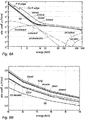
- Figures 6A and 6B plot the attenuation coefficients for the interactions between X-rays and several soft human tissues as a function of photon energy according to the well-known ICRU-4, or "ICRU four component” model) and its decomposition into different contributions: coherent scattering, incoherent scattering, photoelectric absorption, pair creation from nuclei and atoms. Only bones show clear absorption edges of P and Ca. Absorption edges in soft tissue (fat, blood, and breast) are almost invisible in this scale. The total ICRU-4 absorption coefficient is also plotted (thickest line).
- Figure 6B shows a zoom into a range of interest with additional tissues (lung, muscle, brain). Except for bones, the differences in absorption are within ⁇ 10% compared to ICRU-4.
- the mean variation of the attenuation coefficient of ICRU-4 component tissue can be well approximated by a constant attenuation of 5.3% per 10 keV within the energy interval 60 ⁇ E [keV] ⁇ 80 (dashed line on figure 6B ).
- Figure 7 is a density plot of the K ⁇ 1 absorption as a function of penetration depth in ICRU-4 soft tissue and atomic number. It can be seen that elements with Z ⁇ 20 cannot be used, as the corresponding XRF radiation is completely absorbed even by a negligible depth of soft tissue. Use of elements with Z ⁇ 30 is generally impractical, and elements with Z ⁇ 50 will be preferred.
- X-ray attenuation is present for the incoming beam and for the outgoing XRF radiation even though the energies can be quite different (i.e. the X-ray beam can have energies of several hundreds of keV up to several MeV).
- the filtered flux F 2,P is considered to be, a priori, well known. This might be the case because of a well calibrated tube and filter setup or by direct flux measurement or any combination of both.
- the fluorescence generator function G(E,m np ,Z np ) depends on the cross section for photoelectric interaction ⁇ PE (E), which itself depends on the photon energy E, the total mass of the fluorescence particles m np within the primary beam, and the fluorescence yield y(Z) of the fluorescence element.
- E photoelectric interaction
- E the total mass of the fluorescence particles m np within the primary beam
- y(Z) of the fluorescence element y(Z) of the fluorescence element.
- G E m np Z np m np m atom ⁇ ⁇ PE E ⁇ y Z np 4 ⁇ r 2
- r is the distance from the detector and the target point (estimated e.g. using independently-acquired tomographic information) and
- m atom is the atomic mass number of the metal element constituting the nanoparticles. If the nanoparticles are made of an alloy, individual fluorescence generator
- the mean attenuation constant d ⁇ abs, P is used to define the body attenuation according to Eq. (7). This is done by computing the relative flux attenuation at two different energies within the measured spectral flux density F 5 (E). For this purpose, the non-attenuated flux ratio at these energies must be clearly defined, while the non-attenuated flux itself can be unknown.
- the K ⁇ and K ⁇ XRF line emissions fulfill this requirement as their ratio is a material dependent constant. The energy difference between the two lines results in a slightly less attenuated K ⁇ flux compared to the K ⁇ flux.
- the K ⁇ 1 -to-K ⁇ 1 ratio ⁇ is used to quantify the ratio between the two fluxes, while ⁇ ⁇ represents the ratio between ⁇ (d) - the K ⁇ 1 -to-K ⁇ 1 ratio after some absorption in ICRU4 tissue - and the unabsorbed ⁇ 0 .
- FIG. 2A shows the energy of the K ⁇ 1 and K ⁇ 1 fluorescence lines as a function of atomic number; figure 2B , the difference of these energies and figure 2C the resulting flux ratio difference ⁇ ⁇ as a function of the absorption length in soft tissue (ICRU4) and the atomic number Z.
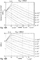
- ⁇ ⁇ rel ⁇ ⁇ b / a which is shown on figures 3A, 3B, 3C and 3D for different statistics of the fluorescence flux F 4 (100 counts for fig. 3A , 1000 counts for figure 3B , 10,000 counts for figure 3C and 100,000 counts for figure 3D ).
- the kerma does not take into account that some fraction of the kinetic energy can escape - for example by Bremsstrahlung - from mass element dm.
- the mass energy absorption coefficient involves this effect and is defined as:
- the factor g represents the average fraction of the kinetic energy of secondary charged particles (produced in all the types of interactions) that is subsequently lost in radiative (photon-emitting) energy-loss processes as the particles slow to rest in the medium [Hubbell and Seltzer, 1999]. For details on the calculation of g, see also Hubbell and Seltzer [1999]. Tabulated values for ⁇ tr and ⁇ en for ICRU 4-component soft tissue can be found in the same reference. Figure 4 shows the mass attenuation coefficient ⁇ en / ⁇ and the mass energy-absorption coefficient ⁇ en / ⁇ for 4-component soft tissue.
- the absorbed dose D is more interesting than the kerma K, but it should be stressed that the inventive approach allows us to compute both quantities.
- F 3,P (E) i.e. the energy resolved flux at the tumor level
- K and D the integrated dosimetric quantities
- the presented approach also allows measuring the total mass of nanoparticles m np at the tumor position.
- the total mass m np allows correcting for the, up to now, neglected physical dose enhancement caused by the increased absorption by high-Z nanoparticles.
- M ICRU4 and M np are the mass ratios for soft tumor tissue (with mass m tumor ) and for the material of the nanoparticles, respectively.
- m np is an important item of information additional to the absorbed dose D, because the enhancement of radiosensitization by nanoparticles is believed to be caused by additional chemical and biological effects of the irradiated nanoparticles that exceed the physical dose enhancement by far.
- Cheng et al. [2012] report a chemical enhancement that exceeds the physical expected enhancement by a factor of about 2000. Therefore, the total mass m np not only allows correcting for the neglected physical dose enhancement but is also an important input parameter for chemical and biological models.
- the dose/kerma can be summarized with the following steps:
- nanoparticle mass also has to be determined:
- Figure 5 provides an outline of the inventive method.
- Nanoparticles may be "atomic", i.e. comprising a single heavy metal such as Hf or Au or compound (e.g. Au+Hf, Au+Bi, etc.).
- the beam type and more particularly its tube voltage and therefore maximum energy E max has also to be chosen.
- diagnostic E max ⁇ 150 keV
- orthovoltage 200 keV ⁇ E max ⁇ 500 keV
- megavoltage (1 MeV ⁇ E max ⁇ 6 Mev)
- the filter material(s) and thickness are then chosen, also taking into account the choice of nanoparticle material(s).
- the filter characteristics and the beam type determine the filtered flux F 2 , which can be either measured or computed.
- the nanoparticle material(s) and the beam type allow choosing the observation angle ⁇ .
- the nanoparticle-loaded tumor is irradiated through the filter, XRF radiation is recorded at observation angle ⁇ and the K ⁇ /K ⁇ ratio is computed for two symmetrical configurations of the apparatus. This allows computing F 3,A , F 3,B , att A , att B , F 5,A , F 5,B , which in turn allows computing the dose D received by the tumor and the actual nanoparticle mass m np .
- the dimensioning of the filter, the choice of the material of which the nanoparticles are made and that of the optimal detection angle ⁇ are important issues for optimizing the sensitivity of the invention. They will be considered in detail in the following.
- the idea behind using a filter is to enhance the signal-to-noise ratio of XRF measurements which uses broad band X-ray emitters, such as X-ray tubes, as primary sources. It applies for all kind of X-ray tubes, i.e. diagnostic tubes (E max ⁇ 150 keV), orthovoltage tubes (200 keV ⁇ E max ⁇ 500 keV), and mega-voltage tubes (E max >1000 keV).
- the filter is used to reduce the undesirable X-ray flux of the beam within a specific energy interval.
- the combination of this filter with a properly chosen observation angle ⁇ allows reducing the background around the observed XRF lines.
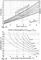
- the choice of the observation angle ⁇ depends on two independent considerations. First, according to the general properties of coherent and incoherent scattering, ⁇ should be close to 90° in order to reduce the scattered background component, see Fig. 9A and 9B . This is true for any kind of filter. Second, ⁇ is chosen according to filter specific considerations in order to create an energy window with a reduced background flux at the XRF energy. Finally, the two considerations must result in a compromise for ⁇ . This can be done by choosing the filter material in a way that the optimal angle for filtering (see Fig. 13 ) results in ⁇ close to 90°.
- a filter that reduces the background radiation at the energy of the XRF lines is highly desirable as it increases the signal-to-noise ratio of the measurement. This is especially true for setup configurations with a large background radiation that results from scattered photons of the primary beam.
- the XRF lines of a target material are produced by the integrated flux above the corresponding absorption edge of the target material.
- the absorption edge of an element is always at higher energies than the respective XRF lines. Therefore, an ideal filter would filter out all X-rays with an energy below the absorption edge of the target material and pass all X-rays with higher energies (see figure 8C ). In this way, the XRF lines could be detected within a low background.
- a sharp falling edge of the transmittance of a material for increasing energies is realized by the photoelectric absorption at the corresponding absorption edge, see Fig. 8B , wherein the continuous line corresponds to a "thick" filter and the dashed one to a "thin” one.
- the position of the absorption edge depends on the filter material but the general shape of the transmittance curve around the absorption edge (i.e. the step downwards followed by a slight increase for higher energies) is independent of the type of material.
- the filter thickness defines the depth of the step of the transmittance curve at the absorption edge.
- Figure 8A corresponds to an X-ray filter without absorption edges, whose transmittance gently increases with photon energy.
- the principal idea is to shape the primary X-ray beam in a way that it has an energy interval with a reduced flux. This region of reduced background is then shifted to the position of the XRF lines by incoherent scattering.
- the dominant photon interactions with the target material are coherent scattering, incoherent scattering (often misnamed as Compton scattering), and photoelectric absorption.
- the observation angle for the XRF detection is typically chosen ⁇ >0° in order to be "out of the beam" in a low background environment. Therefore, only coherent and incoherent scattering contribute to the background radiation and photoelectric absorption can be neglected for the following discussion. Furthermore, the discussion is limited to the case of unpolarized X-rays, as this is the usual case for the primary radiation.
- E sc E 1 + E 511 keV 1 ⁇ cos ⁇
- the case n > 0 can only be applied if the energy difference between the fluorescence line and the absorption edge of the filter is smaller than the maximal energy loss caused by incoherent scattering (i.e. for 180° back scattering).
- the K ⁇ 1 line which is the dominant XRF line
- this condition can be reached for target materials with Z target ⁇ 65, see Fig. 11 and Fig. 14
- the more energetic K ⁇ 1 line Z target ⁇ 41 is required, see Fig. 15 .
- the minimal required atomic number of the target Z target,min to reach the case n > 0 are listed in Table 1.
- the filter thickness is chosen in a way to maximize the signal-to-noise ratio of the K ⁇ 1 fluorescence line.
- the calculations for other fluorescence lines can be done in an equivalent way.
- the flux F 2 is slightly modified by human tissue absorption. While the associated total flux reduction cannot be neglected for an accurate dose calculation, it is of no interest for the SNR calculation due to the normalization.
- the reshaping of the spectra by the human tissue is of importance, but it is considered to be small compared to the reshaping effect of the filter. Therefore, for the filter thickness optimization, F 2 (E) ⁇ F 3 (E) is assumed.
- the flux at the tumor level F 3 (E) is contributing to the signal and to the noise generation in different ways so that an optimal filter thickness can be estimated.
- the fluorescence signal S results from all photons with an energy above the K-edge of the target EK weighted with the probability for photoelectric absorption ⁇ PE (E):
- ⁇ PE ⁇ E ⁇ PE E ⁇ PE E K
- Figures 16A and 16B show the normalized cross section and the cumulative photoelectric distribution CDF PE for the photoelectric effect in gold.
- the maximal tube energy should be in the range of several 100 keV. Above several MeV the signal generation saturates and is close to its maximal value.
- E max is no longer listed explicitly in the following equations.
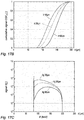
- the cumulative distribution function CDFS(E) shows how the signal accumulates with energy and is for illustrative purposes only.
- Figures 17C and 17D correspond to a mercury filter.
- the noise rate N affecting the XRF signal is proportional to the number of photons per unit time within an interval ⁇ E sc around the fluorescence line in the scattered spectrum (with flux F 4 ); this interval is, in the following, called the fluorescence interval.
- this interval is, in the following, called the fluorescence interval.
- the different curves correspond to simulations obtained using different noise values N c (0, 2.5.10 -4 , 5.10 -4 , 7.5.10 -4 , 1.10 -3 2.10 -3 for Fig.
- the calculated spectra are modified by the filter absorption, the detector efficiency, and the detector resolution. After adding the constant noise the calculated spectra are normalized in order to compare it with the normalized measured spectrum. Even though there remain some discrepancies between the model and the measured data, the constant noise level within the noise interval can be estimated at N c ⁇ 0.0005 for the direct beam and N c ⁇ 0.0040 for the scattered beam. For the direct beam, no target sample was used. Therefore, the noise component which originates from multiple scattering in the sample is not present in this measurement, which results in a considerably lower N c . The discrepancies between the measured flux and the calculated ones originate from an energy dependence of the constant noise component which is ignored because only the noise within the noise interval is of relevance.
- the filter can be chosen in three steps:
- the value of the calculated SNR does represent the true SNR with a factor of proportionality. Nevertheless, the values can be used to compare the different conditions (filter material, filter thickness, tube voltage) and to obtain the optimal filter thickness.
- the energy resolution of the used X-ray detector system smears the steep theoretical K-edge into the noise interval. Therefore, it is necessary to shift the K-edge to even lower energies in order to position the full XRF peak in a low background environment.
- the filter fluorescence lines can be close to the XRF lines of the target. This case can be avoided by using a different selection for the filter material and the observation angle.
- Multiple incoherent scattering can shift:
Landscapes
- Health & Medical Sciences (AREA)
- Life Sciences & Earth Sciences (AREA)
- Engineering & Computer Science (AREA)
- Biomedical Technology (AREA)
- Medical Informatics (AREA)
- Animal Behavior & Ethology (AREA)
- General Health & Medical Sciences (AREA)
- Nuclear Medicine, Radiotherapy & Molecular Imaging (AREA)
- Veterinary Medicine (AREA)
- Pathology (AREA)
- Radiology & Medical Imaging (AREA)
- Public Health (AREA)
- Heart & Thoracic Surgery (AREA)
- Molecular Biology (AREA)
- Surgery (AREA)
- Physics & Mathematics (AREA)
- High Energy & Nuclear Physics (AREA)
- Biophysics (AREA)
- Optics & Photonics (AREA)
- Apparatus For Radiation Diagnosis (AREA)
Claims (10)
- Vorrichtung zum Durchführen einer nanopartikelgestützten externen Strahlentherapie, wobei die Vorrichtung Folgendes umfasst:- ein Röntgenspektrometer (SPM), das eine optische Achse (SOA) aufweist,- eine Röntgenquelle (XRS), die dafür konfiguriert ist, einen Röntgenstrahl (XRB) entlang einer Ausbreitungsrichtung (PRD) auszustrahlen,- einen Röntgenfilter (F), der auf der Ausbreitungsachse des Röntgenstrahls zwischen der Röntgenquelle und einem Zielpunkt (TP) angeordnet und dafür konfiguriert ist, Röntgenstrahlen innerhalb eines vorbestimmten Bereichs des Spektrums des Röntgenstrahls abzuschwächen, und- eine mobile Haltestruktur (MHS), die dafür konfiguriert ist, den Röntgenfilter und das Röntgenspektrometer in einer ersten (A) und einer zweiten (B) relativen Position zu halten und von der ersten zu der zweiten relativen Position zu wechseln, während gleichzeitig das Positionieren eines Patientenkörperteils (PB) in einem Zielbereich, der den Zielpunkt (TP) einschließt, ermöglicht wird,und wobei- die erste und die zweite relative Position des Röntgenfilters und des Röntgenspektrometers derart sind, dass der von der Röntgenquelle (XRS) ausgestrahlte Röntgenstrahl (XRB) den Röntgenfilter (F) durchquert, bevor er den Zielpunkt (TP) erreicht, wobei die Ausbreitungsrichtung (PRD) des Röntgenstrahls einen von 0° und 180° verschiedenen Winkel θ mit der optischen Achse des Röntgenspektrometers bildet,dadurch gekennzeichnet, dass:- die mobile Haltestruktur dafür konfiguriert ist, die zweite relative Position durch Umkehren der relativen Positionen des Röntgenfilters und des Röntgenspektrometers in Bezug auf den Patientenkörperteil zu erreichen.
- Vorrichtung nach Anspruch 1, wobei der durch die Ausbreitungsachse des Röntgenstrahls und die optische Achse des Röntgenspektrometers gebildete Winkel θ, gemessen unter Berücksichtigung der hin zu dem Spektrometer gerichteten optischen Achse, größer als oder gleich 90° ist.
- Vorrichtung nach einem der vorhergehenden Ansprüche, wobei:- das Spektrum des Röntgenstrahls (F2,A, F2,B) nach Durchqueren des Röntgenfilters eine K-Kante mindestens eines Metallelements einschließt, das eine Ordnungszahl Z größer als oder gleich 30 aufweist,- das Röntgenspektrometer (SPM) in einem Spektralbereich empfindlich ist, der mindestens zwei unterschiedliche Fluoreszenzlinien des Metallelements oder der Metallelemente einschließt, und- der vorbestimmte Bereich des Spektrums des Röntgenstrahls, innerhalb dessen der Röntgenfilter Röntgenstrahlen abschwächt, zwei Photonenenergien einschließt, die, wenn sie durch Streuen um den Winkel θ abwärts verschoben werden, mit den zwei unterschiedlichen Fluoreszenzlinien übereinstimmen.
- Vorrichtung nach Anspruch 2, wobei das Metallelement oder jedes Metallelement eine Ordnungszahl Z, größer als oder gleich 50 aufweist.
- Vorrichtung nach Anspruch 4, wobei das oder ein Metallelement Gold ist und der Filter ein Metall umfasst, das unter Osmium und Iridium gewählt ist.
- Vorrichtung nach einem der vorhergehenden Ansprüche, die ferner einen Prozessor (PR) umfasst, der für Folgendes konfiguriert oder programmiert ist:- Empfangen erster Daten von dem Röntgenspektrometer, die ein erstes Röntgenspektrum darstellen, das beim Versetzen der Vorrichtung in eine erste Konfiguration erfasst wird, die der ersten relativen Position des Röntgenfilters und des Röntgenspektrometers entspricht,- Empfangen zweiter Daten von dem Röntgenspektrometer, die ein zweites Röntgenspektrum darstellen, das beim Versetzen der Vorrichtung in eine zweite Konfiguration erfasst wird, die der zweiten relativen Position des Röntgenfilters und des Röntgenspektrometers entspricht,- Verarbeiten der ersten und der zweiten Daten, um eine Röntgendosis zu bestimmen, die durch die Vorrichtung an einem Zielbereich, der den Zielpunkt umgibt, abgegeben wird.
- Vorrichtung nach Anspruch 6, wobei der Prozessor für Folgendes konfiguriert oder programmiert ist:- Berechnen eines ersten Intensitätsverhältnisses zwischen einer ersten und einer zweiten Fluoreszenzlinie, die innerhalb des ersten Röntgenspektrums enthalten sind, wenn sich die Vorrichtung in ihrer ersten Konfiguration befindet,- Berechnen eines zweiten Intensitätsverhältnisses zwischen der ersten und der zweiten Fluoreszenzlinie, die innerhalb des zweiten Röntgenspektrums enthalten sind, wenn sich die Vorrichtung in ihrer zweiten Konfiguration befindet,- Berechnen, aus dem ersten und dem zweiten Intensitätsverhältnis und aus Daten, die eine Röntgenabsorption von Körpergeweben darstellen, einer ersten und einer zweiten Röntgenabschwächung und- Berechnen der Röntgendosis aus der ersten und der zweiten Röntgendämpfung, aus Daten, die eine spektrale Flussdichte des Röntgenstrahls nach dem Durchqueren des Röntgenfilters darstellen, und aus Daten, die eine Röntgenabsorption von Körpergeweben darstellen.
- Vorrichtung nach Anspruch 7, wobei der Prozessor ferner für Folgendes konfiguriert oder programmiert ist:- Berechnen einer Metall-Nanopartikelmasse innerhalb des Zielbereichs aus der ersten und der zweiten Röntgenabschwächung, aus Daten, die eine spektrale Flussdichte des Röntgenstrahls nach dem Durchqueren des Röntgenfilters darstellen, aus Daten, die ein Röntgenabsorption von Körpergeweben darstellen, und aus Daten, die Röntgenfluoreszenzeigenschaften von Metall-Nanopartikeln darstellen.
- Vorrichtung nach einem der vorhergehenden Ansprüche, wobei die mobile Haltestruktur (MHS) ferner zum Halten der Röntgenquelle und zum Umkehren der Positionen des Röntgenspektrometers und eines Ensembles, das die Röntgenquelle und das Röntgenfilter umfasst, im Verhältnis zu dem Zielpunkt geeignet ist.
- Vorrichtung nach einem der Ansprüche 1 bis 8, wobei die mobile Haltestruktur (MHS) ferner zum Halten des Patientenkörperteils und zum Wechseln von der ersten zu der zweiten relativen Position durch Drehen des Patientenkörperteils und eines von dem Röntgenspektrometer und einem Ensemble, das die Röntgenquelle und das Röntgenfilter umfasst, im Verhältnis zu dem Zielpunkt geeignet ist.
Applications Claiming Priority (1)
| Application Number | Priority Date | Filing Date | Title |
|---|---|---|---|
| EP17290157 | 2017-12-07 |
Publications (2)
| Publication Number | Publication Date |
|---|---|
| EP3494886A1 EP3494886A1 (de) | 2019-06-12 |
| EP3494886B1 true EP3494886B1 (de) | 2021-05-12 |
Family
ID=60923322
Family Applications (1)
| Application Number | Title | Priority Date | Filing Date |
|---|---|---|---|
| EP18207716.4A Active EP3494886B1 (de) | 2017-12-07 | 2018-11-22 | Vorrichtung zur durchführung einer nanopartikelgestützten externen strahlentherapie |
Country Status (2)
| Country | Link |
|---|---|
| US (1) | US10709904B2 (de) |
| EP (1) | EP3494886B1 (de) |
Families Citing this family (1)
| Publication number | Priority date | Publication date | Assignee | Title |
|---|---|---|---|---|
| WO2026078299A1 (en) * | 2024-10-10 | 2026-04-16 | Fenno-Aurum Oy | A measurement arrangement and a method for measuring concentration of gold in a sample |
Family Cites Families (5)
| Publication number | Priority date | Publication date | Assignee | Title |
|---|---|---|---|---|
| US8238516B2 (en) * | 2008-01-09 | 2012-08-07 | Kabushiki Kaisha Toshiba | Radiotherapy support apparatus |
| WO2011084625A1 (en) * | 2009-12-16 | 2011-07-14 | Georgia Tech Research Corporation | Systems and methods for x-ray flourescence computed tomography imaging with nanoparticles |
| US10602991B2 (en) * | 2011-07-06 | 2020-03-31 | Varian Medical Systems, Inc. | Functional and physical imaging using radiation |
| WO2015031675A1 (en) * | 2013-08-28 | 2015-03-05 | The Regents Of The University Of California | Nanoparticle assisted scanning focusing x-ray fluorescence imaging and enhanced treatment |
| WO2017147603A1 (en) * | 2016-02-26 | 2017-08-31 | Rothschild Peter J | In-vivo detection of lead in bone |
-
2018
- 2018-11-22 EP EP18207716.4A patent/EP3494886B1/de active Active
- 2018-11-28 US US16/203,534 patent/US10709904B2/en active Active
Non-Patent Citations (1)
| Title |
|---|
| None * |
Also Published As
| Publication number | Publication date |
|---|---|
| EP3494886A1 (de) | 2019-06-12 |
| US10709904B2 (en) | 2020-07-14 |
| US20190175948A1 (en) | 2019-06-13 |
Similar Documents
| Publication | Publication Date | Title |
|---|---|---|
| Sjögren et al. | Electron contamination in clinical high energy photon beams | |
| JP7536057B2 (ja) | 中性子捕捉療法システム及び中性子捕捉療法システム用の放射線検出方法 | |
| US8355482B2 (en) | Radiotherapy apparatus | |
| Ahmad et al. | Optimized detector angular configuration increases the sensitivity of x-ray fluorescence computed tomography (XFCT) | |
| KR20240055138A (ko) | 단색 엑스선 영상 시스템 및 방법 | |
| US11992351B2 (en) | Method, apparatus, and system for energy-resolved scatter imaging during radiation therapy | |
| Gong et al. | Optimization of the Compton camera for measuring prompt gamma rays in boron neutron capture therapy | |
| Parsons et al. | Beam generation and planar imaging at energies below 2.40 MeV with carbon and aluminum linear accelerator targets | |
| Lopes et al. | Optimization of collimator designs for real-time proton range verification by measuring prompt gamma rays | |
| US10709904B2 (en) | Apparatus for performing nanoparticle-assisted external beam radiotherapy and method carried out using said apparatus | |
| Knöös et al. | Modelling of an orthovoltage x-ray therapy unit with the EGSnrc Monte Carlo package | |
| US11517273B2 (en) | Dual energy X-ray imaging apparatus | |
| Ding | An investigation of accelerator head scatter and output factor in air | |
| Simões et al. | Dose-free monitoring of radiotherapy treatments with scattered photons: First experimental results at a 6-MV linac | |
| Motz et al. | X‐ray scatter background signals in transmission radiography | |
| CN115910418A (zh) | 一种基于蒙特卡罗模拟的辐射防护箱体的制备方法 | |
| Ahmed et al. | Development of an attenuation correction method for direct x‐ray fluorescence (XRF) imaging utilizing gold L‐shell XRF photons | |
| Hwang | Characterization and applications of laser-Compton x-ray source | |
| CN120435675A (zh) | 测量硼中子捕捉治疗效果的测量装置以及测量方法 | |
| Oancea et al. | LET spectra behind high-density titanium and stainless steel hip implants irradiated with a therapeutic proton beam | |
| Ali et al. | Plane polarized x-ray fluorescence system for the in vivo measurement of platinum in head and neck tumours | |
| Hartmann et al. | Towards fragment distinction in therapeutic carbon ion beams: A novel experimental approach using the Timepix detector | |
| WO2023004193A1 (en) | Systems and methods for megavoltage x-ray induced positron emission (mvipe) imaging | |
| Reynoso et al. | Comparison of filtered x-ray spectra and depth doses derived from a hybrid Monte Carlo model of an orthovoltage x-ray unit with experimental measurements | |
| Rosa et al. | Range verification for eye proton therapy based on proton-induced x-ray emissions from implanted metal markers |
Legal Events
| Date | Code | Title | Description |
|---|---|---|---|
| PUAI | Public reference made under article 153(3) epc to a published international application that has entered the european phase |
Free format text: ORIGINAL CODE: 0009012 |
|
| STAA | Information on the status of an ep patent application or granted ep patent |
Free format text: STATUS: REQUEST FOR EXAMINATION WAS MADE |
|
| 17P | Request for examination filed |
Effective date: 20181122 |
|
| AK | Designated contracting states |
Kind code of ref document: A1 Designated state(s): AL AT BE BG CH CY CZ DE DK EE ES FI FR GB GR HR HU IE IS IT LI LT LU LV MC MK MT NL NO PL PT RO RS SE SI SK SM TR |
|
| AX | Request for extension of the european patent |
Extension state: BA ME |
|
| STAA | Information on the status of an ep patent application or granted ep patent |
Free format text: STATUS: EXAMINATION IS IN PROGRESS |
|
| 17Q | First examination report despatched |
Effective date: 20200309 |
|
| GRAP | Despatch of communication of intention to grant a patent |
Free format text: ORIGINAL CODE: EPIDOSNIGR1 |
|
| STAA | Information on the status of an ep patent application or granted ep patent |
Free format text: STATUS: GRANT OF PATENT IS INTENDED |
|
| GRAJ | Information related to disapproval of communication of intention to grant by the applicant or resumption of examination proceedings by the epo deleted |
Free format text: ORIGINAL CODE: EPIDOSDIGR1 |
|
| STAA | Information on the status of an ep patent application or granted ep patent |
Free format text: STATUS: EXAMINATION IS IN PROGRESS |
|
| INTG | Intention to grant announced |
Effective date: 20210114 |
|
| GRAP | Despatch of communication of intention to grant a patent |
Free format text: ORIGINAL CODE: EPIDOSNIGR1 |
|
| STAA | Information on the status of an ep patent application or granted ep patent |
Free format text: STATUS: GRANT OF PATENT IS INTENDED |
|
| INTC | Intention to grant announced (deleted) | ||
| INTG | Intention to grant announced |
Effective date: 20210211 |
|
| GRAS | Grant fee paid |
Free format text: ORIGINAL CODE: EPIDOSNIGR3 |
|
| GRAA | (expected) grant |
Free format text: ORIGINAL CODE: 0009210 |
|
| STAA | Information on the status of an ep patent application or granted ep patent |
Free format text: STATUS: THE PATENT HAS BEEN GRANTED |
|
| AK | Designated contracting states |
Kind code of ref document: B1 Designated state(s): AL AT BE BG CH CY CZ DE DK EE ES FI FR GB GR HR HU IE IS IT LI LT LU LV MC MK MT NL NO PL PT RO RS SE SI SK SM TR |
|
| REG | Reference to a national code |
Ref country code: GB Ref legal event code: FG4D |
|
| REG | Reference to a national code |
Ref country code: CH Ref legal event code: EP |
|
| REG | Reference to a national code |
Ref country code: DE Ref legal event code: R096 Ref document number: 602018016984 Country of ref document: DE |
|
| REG | Reference to a national code |
Ref country code: IE Ref legal event code: FG4D |
|
| REG | Reference to a national code |
Ref country code: AT Ref legal event code: REF Ref document number: 1391628 Country of ref document: AT Kind code of ref document: T Effective date: 20210615 |
|
| REG | Reference to a national code |
Ref country code: LT Ref legal event code: MG9D |
|
| REG | Reference to a national code |
Ref country code: AT Ref legal event code: MK05 Ref document number: 1391628 Country of ref document: AT Kind code of ref document: T Effective date: 20210512 |
|
| REG | Reference to a national code |
Ref country code: NL Ref legal event code: MP Effective date: 20210512 |
|
| PG25 | Lapsed in a contracting state [announced via postgrant information from national office to epo] |
Ref country code: BG Free format text: LAPSE BECAUSE OF FAILURE TO SUBMIT A TRANSLATION OF THE DESCRIPTION OR TO PAY THE FEE WITHIN THE PRESCRIBED TIME-LIMIT Effective date: 20210812 Ref country code: AT Free format text: LAPSE BECAUSE OF FAILURE TO SUBMIT A TRANSLATION OF THE DESCRIPTION OR TO PAY THE FEE WITHIN THE PRESCRIBED TIME-LIMIT Effective date: 20210512 Ref country code: FI Free format text: LAPSE BECAUSE OF FAILURE TO SUBMIT A TRANSLATION OF THE DESCRIPTION OR TO PAY THE FEE WITHIN THE PRESCRIBED TIME-LIMIT Effective date: 20210512 Ref country code: LT Free format text: LAPSE BECAUSE OF FAILURE TO SUBMIT A TRANSLATION OF THE DESCRIPTION OR TO PAY THE FEE WITHIN THE PRESCRIBED TIME-LIMIT Effective date: 20210512 Ref country code: HR Free format text: LAPSE BECAUSE OF FAILURE TO SUBMIT A TRANSLATION OF THE DESCRIPTION OR TO PAY THE FEE WITHIN THE PRESCRIBED TIME-LIMIT Effective date: 20210512 |
|
| PG25 | Lapsed in a contracting state [announced via postgrant information from national office to epo] |
Ref country code: GR Free format text: LAPSE BECAUSE OF FAILURE TO SUBMIT A TRANSLATION OF THE DESCRIPTION OR TO PAY THE FEE WITHIN THE PRESCRIBED TIME-LIMIT Effective date: 20210813 Ref country code: IS Free format text: LAPSE BECAUSE OF FAILURE TO SUBMIT A TRANSLATION OF THE DESCRIPTION OR TO PAY THE FEE WITHIN THE PRESCRIBED TIME-LIMIT Effective date: 20210912 Ref country code: NO Free format text: LAPSE BECAUSE OF FAILURE TO SUBMIT A TRANSLATION OF THE DESCRIPTION OR TO PAY THE FEE WITHIN THE PRESCRIBED TIME-LIMIT Effective date: 20210812 Ref country code: PT Free format text: LAPSE BECAUSE OF FAILURE TO SUBMIT A TRANSLATION OF THE DESCRIPTION OR TO PAY THE FEE WITHIN THE PRESCRIBED TIME-LIMIT Effective date: 20210913 Ref country code: PL Free format text: LAPSE BECAUSE OF FAILURE TO SUBMIT A TRANSLATION OF THE DESCRIPTION OR TO PAY THE FEE WITHIN THE PRESCRIBED TIME-LIMIT Effective date: 20210512 Ref country code: LV Free format text: LAPSE BECAUSE OF FAILURE TO SUBMIT A TRANSLATION OF THE DESCRIPTION OR TO PAY THE FEE WITHIN THE PRESCRIBED TIME-LIMIT Effective date: 20210512 Ref country code: SE Free format text: LAPSE BECAUSE OF FAILURE TO SUBMIT A TRANSLATION OF THE DESCRIPTION OR TO PAY THE FEE WITHIN THE PRESCRIBED TIME-LIMIT Effective date: 20210512 Ref country code: RS Free format text: LAPSE BECAUSE OF FAILURE TO SUBMIT A TRANSLATION OF THE DESCRIPTION OR TO PAY THE FEE WITHIN THE PRESCRIBED TIME-LIMIT Effective date: 20210512 |
|
| PG25 | Lapsed in a contracting state [announced via postgrant information from national office to epo] |
Ref country code: NL Free format text: LAPSE BECAUSE OF FAILURE TO SUBMIT A TRANSLATION OF THE DESCRIPTION OR TO PAY THE FEE WITHIN THE PRESCRIBED TIME-LIMIT Effective date: 20210512 |
|
| PG25 | Lapsed in a contracting state [announced via postgrant information from national office to epo] |
Ref country code: SM Free format text: LAPSE BECAUSE OF FAILURE TO SUBMIT A TRANSLATION OF THE DESCRIPTION OR TO PAY THE FEE WITHIN THE PRESCRIBED TIME-LIMIT Effective date: 20210512 Ref country code: SK Free format text: LAPSE BECAUSE OF FAILURE TO SUBMIT A TRANSLATION OF THE DESCRIPTION OR TO PAY THE FEE WITHIN THE PRESCRIBED TIME-LIMIT Effective date: 20210512 Ref country code: ES Free format text: LAPSE BECAUSE OF FAILURE TO SUBMIT A TRANSLATION OF THE DESCRIPTION OR TO PAY THE FEE WITHIN THE PRESCRIBED TIME-LIMIT Effective date: 20210512 Ref country code: EE Free format text: LAPSE BECAUSE OF FAILURE TO SUBMIT A TRANSLATION OF THE DESCRIPTION OR TO PAY THE FEE WITHIN THE PRESCRIBED TIME-LIMIT Effective date: 20210512 Ref country code: RO Free format text: LAPSE BECAUSE OF FAILURE TO SUBMIT A TRANSLATION OF THE DESCRIPTION OR TO PAY THE FEE WITHIN THE PRESCRIBED TIME-LIMIT Effective date: 20210512 Ref country code: CZ Free format text: LAPSE BECAUSE OF FAILURE TO SUBMIT A TRANSLATION OF THE DESCRIPTION OR TO PAY THE FEE WITHIN THE PRESCRIBED TIME-LIMIT Effective date: 20210512 Ref country code: DK Free format text: LAPSE BECAUSE OF FAILURE TO SUBMIT A TRANSLATION OF THE DESCRIPTION OR TO PAY THE FEE WITHIN THE PRESCRIBED TIME-LIMIT Effective date: 20210512 |
|
| REG | Reference to a national code |
Ref country code: DE Ref legal event code: R097 Ref document number: 602018016984 Country of ref document: DE |
|
| PLBE | No opposition filed within time limit |
Free format text: ORIGINAL CODE: 0009261 |
|
| STAA | Information on the status of an ep patent application or granted ep patent |
Free format text: STATUS: NO OPPOSITION FILED WITHIN TIME LIMIT |
|
| 26N | No opposition filed |
Effective date: 20220215 |
|
| PG25 | Lapsed in a contracting state [announced via postgrant information from national office to epo] |
Ref country code: IS Free format text: LAPSE BECAUSE OF FAILURE TO SUBMIT A TRANSLATION OF THE DESCRIPTION OR TO PAY THE FEE WITHIN THE PRESCRIBED TIME-LIMIT Effective date: 20210912 Ref country code: AL Free format text: LAPSE BECAUSE OF FAILURE TO SUBMIT A TRANSLATION OF THE DESCRIPTION OR TO PAY THE FEE WITHIN THE PRESCRIBED TIME-LIMIT Effective date: 20210512 |
|
| PG25 | Lapsed in a contracting state [announced via postgrant information from national office to epo] |
Ref country code: MC Free format text: LAPSE BECAUSE OF FAILURE TO SUBMIT A TRANSLATION OF THE DESCRIPTION OR TO PAY THE FEE WITHIN THE PRESCRIBED TIME-LIMIT Effective date: 20210512 |
|
| REG | Reference to a national code |
Ref country code: CH Ref legal event code: PL |
|
| PG25 | Lapsed in a contracting state [announced via postgrant information from national office to epo] |
Ref country code: LU Free format text: LAPSE BECAUSE OF NON-PAYMENT OF DUE FEES Effective date: 20211122 Ref country code: IT Free format text: LAPSE BECAUSE OF FAILURE TO SUBMIT A TRANSLATION OF THE DESCRIPTION OR TO PAY THE FEE WITHIN THE PRESCRIBED TIME-LIMIT Effective date: 20210512 Ref country code: BE Free format text: LAPSE BECAUSE OF NON-PAYMENT OF DUE FEES Effective date: 20211130 |
|
| REG | Reference to a national code |
Ref country code: BE Ref legal event code: MM Effective date: 20211130 |
|
| PG25 | Lapsed in a contracting state [announced via postgrant information from national office to epo] |
Ref country code: LI Free format text: LAPSE BECAUSE OF NON-PAYMENT OF DUE FEES Effective date: 20211130 Ref country code: CH Free format text: LAPSE BECAUSE OF NON-PAYMENT OF DUE FEES Effective date: 20211130 |
|
| PG25 | Lapsed in a contracting state [announced via postgrant information from national office to epo] |
Ref country code: IE Free format text: LAPSE BECAUSE OF NON-PAYMENT OF DUE FEES Effective date: 20211122 |
|
| PG25 | Lapsed in a contracting state [announced via postgrant information from national office to epo] |
Ref country code: CY Free format text: LAPSE BECAUSE OF FAILURE TO SUBMIT A TRANSLATION OF THE DESCRIPTION OR TO PAY THE FEE WITHIN THE PRESCRIBED TIME-LIMIT Effective date: 20210512 |
|
| PG25 | Lapsed in a contracting state [announced via postgrant information from national office to epo] |
Ref country code: HU Free format text: LAPSE BECAUSE OF FAILURE TO SUBMIT A TRANSLATION OF THE DESCRIPTION OR TO PAY THE FEE WITHIN THE PRESCRIBED TIME-LIMIT; INVALID AB INITIO Effective date: 20181122 |
|
| PG25 | Lapsed in a contracting state [announced via postgrant information from national office to epo] |
Ref country code: MK Free format text: LAPSE BECAUSE OF FAILURE TO SUBMIT A TRANSLATION OF THE DESCRIPTION OR TO PAY THE FEE WITHIN THE PRESCRIBED TIME-LIMIT Effective date: 20210512 |
|
| PG25 | Lapsed in a contracting state [announced via postgrant information from national office to epo] |
Ref country code: TR Free format text: LAPSE BECAUSE OF FAILURE TO SUBMIT A TRANSLATION OF THE DESCRIPTION OR TO PAY THE FEE WITHIN THE PRESCRIBED TIME-LIMIT Effective date: 20210512 |
|
| PG25 | Lapsed in a contracting state [announced via postgrant information from national office to epo] |
Ref country code: MT Free format text: LAPSE BECAUSE OF FAILURE TO SUBMIT A TRANSLATION OF THE DESCRIPTION OR TO PAY THE FEE WITHIN THE PRESCRIBED TIME-LIMIT Effective date: 20210512 |
|
| PGFP | Annual fee paid to national office [announced via postgrant information from national office to epo] |
Ref country code: DE Payment date: 20251118 Year of fee payment: 8 |
|
| PGFP | Annual fee paid to national office [announced via postgrant information from national office to epo] |
Ref country code: GB Payment date: 20251125 Year of fee payment: 8 |
|
| PGFP | Annual fee paid to national office [announced via postgrant information from national office to epo] |
Ref country code: FR Payment date: 20251125 Year of fee payment: 8 |