EP3494841A1 - Shape memory alloy lumbar support system - Google Patents
Shape memory alloy lumbar support system Download PDFInfo
- Publication number
- EP3494841A1 EP3494841A1 EP18211005.6A EP18211005A EP3494841A1 EP 3494841 A1 EP3494841 A1 EP 3494841A1 EP 18211005 A EP18211005 A EP 18211005A EP 3494841 A1 EP3494841 A1 EP 3494841A1
- Authority
- EP
- European Patent Office
- Prior art keywords
- shape memory
- tension cable
- lumbar support
- memory alloy
- support basket
- Prior art date
- Legal status (The legal status is an assumption and is not a legal conclusion. Google has not performed a legal analysis and makes no representation as to the accuracy of the status listed.)
- Withdrawn
Links
Images


Classifications
-
- B—PERFORMING OPERATIONS; TRANSPORTING
- B64—AIRCRAFT; AVIATION; COSMONAUTICS
- B64D—EQUIPMENT FOR FITTING IN OR TO AIRCRAFT; FLIGHT SUITS; PARACHUTES; ARRANGEMENT OR MOUNTING OF POWER PLANTS OR PROPULSION TRANSMISSIONS IN AIRCRAFT
- B64D11/00—Passenger or crew accommodation; Flight-deck installations not otherwise provided for
- B64D11/06—Arrangements of seats, or adaptations or details specially adapted for aircraft seats
- B64D11/0647—Seats characterised by special upholstery or cushioning features
-
- B—PERFORMING OPERATIONS; TRANSPORTING
- B64—AIRCRAFT; AVIATION; COSMONAUTICS
- B64D—EQUIPMENT FOR FITTING IN OR TO AIRCRAFT; FLIGHT SUITS; PARACHUTES; ARRANGEMENT OR MOUNTING OF POWER PLANTS OR PROPULSION TRANSMISSIONS IN AIRCRAFT
- B64D11/00—Passenger or crew accommodation; Flight-deck installations not otherwise provided for
- B64D11/06—Arrangements of seats, or adaptations or details specially adapted for aircraft seats
- B64D11/0639—Arrangements of seats, or adaptations or details specially adapted for aircraft seats with features for adjustment or converting of seats
-
- A—HUMAN NECESSITIES
- A47—FURNITURE; DOMESTIC ARTICLES OR APPLIANCES; COFFEE MILLS; SPICE MILLS; SUCTION CLEANERS IN GENERAL
- A47C—CHAIRS; SOFAS; BEDS
- A47C7/00—Parts, details, or accessories of chairs or stools
- A47C7/36—Supports for the head or the back
- A47C7/40—Supports for the head or the back for the back
- A47C7/46—Supports for the head or the back for the back with special, e.g. adjustable, lumbar region support profile; "Ackerblom" profile chairs
-
- B—PERFORMING OPERATIONS; TRANSPORTING
- B60—VEHICLES IN GENERAL
- B60N—SEATS SPECIALLY ADAPTED FOR VEHICLES; VEHICLE PASSENGER ACCOMMODATION NOT OTHERWISE PROVIDED FOR
- B60N2/00—Seats specially adapted for vehicles; Arrangement or mounting of seats in vehicles
- B60N2/64—Back-rests or cushions
- B60N2/66—Lumbar supports
- B60N2/667—Lumbar supports having flexible support member bowed by applied forces
- B60N2/6671—Lumbar supports having flexible support member bowed by applied forces with cable actuators
Definitions
- Exemplary embodiments pertain to the art of aircraft seating and more specifically to a shape memory alloy lumbar support system for an aircraft seat.
- Aircraft seats are designed to support the posture of a user by supporting, among other things, the lumbar region of the lower back.
- Current systems for lumbar support in aircraft seating often have multiple parts including rack and pinion mechanisms to achieve buckling of the lumbar basket there by resulting in different profiles of the lumbar support.
- Conventional lumbar supports can include actuation knobs or levers, cable to translate tension or compression from the actuation mechanism to the lumbar basket, and other parts in support of these components. All these components contribute to the increased weight of the seat. Components that are lightweight as required in an aircraft can be costly to manufacture and maintain over the life of the aircraft.
- manually-actuated lumbar support systems do not include controls that automatically adjust to user preferences with the push of a button.
- the lumbar support system includes a deformable lumbar support basket having a proximate end and a distal end.
- the system includes a shape memory alloy tension cable in communication with the proximate end of the deformable lumbar support basket, and in communication with the distal end of the deformable lumbar support basket.
- the shape memory alloy tension cable has a changeable tension length when an electric current is transmitted through the cable.
- the system includes a controller operatively connected with the shape memory alloy tension cable. The controller transmits the electric current through the shape memory alloy tension cable. The electric current causes the shape memory alloy tension cable to deform the lumbar support basket by tension force applied to the proximate end of the deformable lumbar support basket and the distal end of the deformable lumbar support basket.
- a controller for a lumbar support system includes a non-transitory computer-readable memory storing program instructions that, when executed by a processor, cause the processor to receive an actuation signal, and determine, via the actuation signal, a user profile indicative of a magnitude of electric current to deform a deformable lumbar support basket.
- the processor transmits, based on the user profile, an electric current through a shape memory alloy tension cable that has a changeable tension length with the electric current through the cable.
- the shape memory alloy tension cable is in communication with a proximate end of the deformable lumbar support basket, and in communication with a distal end of the deformable lumbar support basket, where the electric current transmitted through the shape memory alloy causes the shape memory alloy tension cable to deform the lumbar support basket by tension force applied by the shape memory alloy tension cable to the proximate end of the deformable lumbar support basket and the distal end of the deformable lumbar support basket.
- FIG. 1 depicts a shape memory lumbar support system 100 according, to an embodiment.
- the lumbar support system 100 includes a controller 102 operatively connected with a switch 116 for switching a power source 118.
- the system includes a deformable lumbar support basket 103 (hereafter support basket 103), and a shape memory alloy tension cable 112 (hereafter tension cable 112) in communication with the support basket 103.
- the support basket 103 is described herein as having a proximate end 104 and a distal end 106.
- the tension cable 112 is in mechanical communication with proximate end 104 and a distal end 106 such that when a current passes through the tension cable 112, the tension cable 112 contracts proportionally with the magnitude of current applied through the tension cable.
- the tension applied to the proximal end 104 and the distal end 106 of the support basket 103 by the tension cable 112 causes the support basket 103 to deform longitudinally 114 by forcing the distal end and proximal end to come towards one another. This deformation of the support basket 103 causes the basket to bow and form an arc that supports the lumbar portion of a user's back.
- the tension mechanism of the tension cable 112 is based on a property of the shape memory alloy from which the cable 112 is constructed. Shape memory alloy contracts when an electric current, heat, or other stimulus (depending on the material) is applied to the cable.
- the connecting ends 110 and 108 of the tension cable 112 include connecting means such that the current from the power source 118 can pass through the cable 112 when the switch 116 is actuated by the controller 102.
- the tension cable 112 is made from shape memory alloy that changes shape according to an amount of current applied to the cable.
- the tension cable 112 may contract by a predetermined number (n) millimeters per milliamp of current. Accordingly, a predetermined response is measurable and recordable in a computer memory such that an individual setting (a magnitude of current) for achieving a desired amount of deformation of the support basket 103 is possible.
- the controller 102 is configured to receive an actuation signal from the actuation switch 101. The controller 102 then determines a user profile associated with the actuation signal by correlating a signal characteristic from the actuation switch to a saved user profile.
- the electric current has a predetermined magnitude corresponding to a tension length of the shape memory alloy tension cable 112.
- the controller 102 transmits the electric current based on the user profile associated with the user identification, which is associated with a magnitude of current to transmit through the tension cable 112 that produces a corresponding amount of deformation in the basket.
- the system 100 can support the lumbar portion of a user's back when the system is installed on an aircraft seat.
- the tension cable 112 is in communication with the proximate end 104 and the distal end 106 of the support basket 103 in various ways, as depicted in the various embodiments of FIG. 2, FIG. 3 , FIG. 4, and FIG. 5 . Each embodied configuration is described in greater detail below.
- the tension cable 112 is attached to the support basket by two ends of the tension cable.
- a first end 110 of the tension cable and a second end 108 of the tension cable 112 are depicted in FIG. 1 as connected rigidly to the proximate end 104 and the distal end 106 in either a fixed fashion via first end of the tension cable 112, or a second end 108 of the tension cable 112, respectively.
- FIG. 2 is a simplified view of the configuration of the shape memory tension cable 112 for the lumbar support system of FIG. 1 .
- FIG. 2 depicts a block diagram of the proximate end 104 and the distal end 106 of the support basket 103.
- the shape memory alloy tension cable 112 includes a first connecting end 202 and a second connecting end 204.
- the first and second connecting ends 202, 204 are rigidly connected with the proximal and distal ends of the support basket, where the end of the tension cable 112 can apply force to the support basket 103 directly because the cable 112 is securely fastened to the basket end. Accordingly, tension force is transmitted to the basket directly through the ends without any mechanical advantage of one or more pins (as shown in FIGS. 3-5 ).
- FIG. 3-5 In FIG.
- the first connecting end 202 rigidly connects to the proximate end 104 of the deformable lumbar support basket 103
- the second connecting end 204 rigidly connects to the distal end 106 of the deformable lumbar support basket 103.
- the transmission causes the tension cable 112 to deform the lumbar support basket 103 with tension force received at the proximate end 104 of the deformable lumbar support basket 103 via the first connecting end 202 of the tension cable 112 and with tension force received at the distal end 106 of the deformable lumbar support basket 103 via the second connecting end 204 of the tension cable 112.
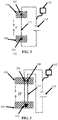
- FIG. 3 is another configuration of a shape memory tension cable 112 for the lumbar support system of FIG. 1 , according to another embodiment.
- the shape memory alloy tension cable 112 includes a first connecting end 206 and a second connecting end 208.
- the first and second connecting ends 206, 208 both rigidly connect to the proximate end 104 of the deformable lumbar support basket 103.
- the distal end 106 includes a pin 210 in communication with the shape memory alloy tension cable 112 such that the electric current transmitted by the controller 102 from the power source 118 through the shape memory alloy tension cable 112 causes the tension cable 112 to deform the lumbar support basket 103 with tension force received at the distal end 106 via the pin and received at the proximate end 104 via the first connecting end 206 and second connecting end 208 of the tension cable 112.
- the mechanical advantage of the tension force applied to the proximate and distal ends 104, 106, of the lumbar basket 103 results in 2F (two times the force applied in the configuration of FIG. 2 at the same given current).
- FIG. 4 is another configuration of a shape memory tension cable 112 for the lumbar support system 100 of FIG. 1 according to an embodiment.
- the configuration of FIG. 4 depicts a first connecting end 202 of the shape memory alloy tension cable 112 rigidly connecting to the distal end 106 of the deformable lumbar support basket 103.
- a second connecting end 204 of the shape memory alloy tension cable 112 rigidly connects to the proximate end 104 of the deformable lumbar support basket 103.
- a first pin 212 rigidly connects to the proximate end 104 of the support basket 103, and is in communication with the shape memory alloy tension cable 112, where the shape memory alloy tension cable 112 loops around the first pin 212 to provide mechanical advantage to the force applied to the distal and proximate ends.
- a second pin 218 rigidly connects to the distal end 106 and is in communication with the shape memory alloy tension cable 112 by providing mechanical advantage to the tension force applied.
- the electric current transmitted by the controller 102 from the power source 118 through the shape memory alloy tension cable 112 causes the shape memory alloy tension cable 112 to deform the lumbar support basket 103 with tension force received at the proximate end 104 via the first pin 212 and via the second connecting end 204 of the tension cable 112.
- the electric current also causes the deformation of the lumbar support basket 103 with tension force received at the distal end 106 via the first connecting end 202 of the shape memory alloy tension cable 112 and the second pin 218.
- the force applied by the shape memory alloy tension cable 112 is three times (3F) the force applied in FIG. 2 .
- FIG. 5 is another configuration of a shape memory tension cable for the lumbar support system of FIG. 1 , according to an embodiment.
- a first connecting end 202 of the shape memory alloy tension cable 112 rigidly connects to the proximate end 104 of the deformable lumbar support basket 103.
- a second connecting end 204 of the shape memory alloy tension cable 112 rigidly connects to the proximate end 104 of the deformable lumbar support basket 103.
- a first pin 212 rigidly connects to the proximate end 104 and is in communication with the shape memory alloy tension cable 112.
- the tension force is transmitted from the shape memory alloy tension cable 112 to the first pin 212 as the cable 112 wraps around the first pin 212 and applies force to the first pin 212 when the shape memory alloy tension cable 112 tenses.
- a second pin 218 and a third pin 228 rigidly connect to the distal end 106 of the support basket 103, and is in communication with the shape memory alloy tension cable 112 as described above with respect to the first pin 212.
- the electric current transmitted by the controller 102 from the power source 118 through the shape memory alloy tension cable 112 causes the tension cable 112 to deform the lumbar support basket 103 with tension force received at the proximate end 104 via the first pin 212 and via the first connecting end 202 of the shape memory alloy tension cable 112, the second connecting end 204 of the tension cable 112 and the first pin 212, and with tension force received at the distal end 106 via the second pin 218 and the third pin 228.
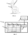
- FIG. 6 is an aircraft seat configured with the lumbar support system of FIG. 1 according to an embodiment. As shown in FIG. 6 , the lumbar support system 100 as shown in FIG. 1 supports the lumbar portion of a user's 602 back.
- FIG. 7 is a controller for a lumbar support system according to an embodiment.
- the controller 102 for the lumbar support system 100 includes a non-transitory computer-readable memory 702 storing program instructions that, when executed by a processor 701, cause the processor 701 to receive an actuation signal, and determine, via the actuation signal, a user profile 710 indicative of a magnitude of electric current 708 to deform a deformable lumbar support basket (e.g., lumbar support basket 103).
- the memory 702 includes user profile information 710 that associates a magnitude setting 708 of the current to apply to the shape memory alloy tension cable 112. A record for each unique user 706 is saved on the memory 702.
- the processor 701 transmits, based on the user profile information 710, an electric current through a shape memory alloy tension cable 112 that has a changeable tension length with the electric current through the cable.
- the shape memory alloy tension cable 112 is in communication with a proximate end of the deformable lumbar support basket, and in communication with a distal end of the deformable lumbar support basket (which can vary according to the embodiments depicted with respect to FIGS. 2-5 ).
- the electric current transmitted through the shape memory alloy tension cable 112 causes the shape memory alloy tension cable 112 to deform the lumbar support basket 103 by tension force applied by the shape memory alloy tension cable 112 to the proximate end 104 of the deformable lumbar support basket 103 and the distal end 106 of the deformable lumbar support basket 103.
Landscapes
- Engineering & Computer Science (AREA)
- Aviation & Aerospace Engineering (AREA)
- Transportation (AREA)
- Mechanical Engineering (AREA)
- Prostheses (AREA)
Abstract
Description
- This application claims priority to Indian Patent Application No.
201711044187 filed December 8, 2017 - Exemplary embodiments pertain to the art of aircraft seating and more specifically to a shape memory alloy lumbar support system for an aircraft seat.
- Aircraft seats are designed to support the posture of a user by supporting, among other things, the lumbar region of the lower back. Current systems for lumbar support in aircraft seating often have multiple parts including rack and pinion mechanisms to achieve buckling of the lumbar basket there by resulting in different profiles of the lumbar support. Conventional lumbar supports can include actuation knobs or levers, cable to translate tension or compression from the actuation mechanism to the lumbar basket, and other parts in support of these components. All these components contribute to the increased weight of the seat. Components that are lightweight as required in an aircraft can be costly to manufacture and maintain over the life of the aircraft. Moreover, manually-actuated lumbar support systems do not include controls that automatically adjust to user preferences with the push of a button.
- Disclosed is a lumbar support system for an aircraft seat. The lumbar support system includes a deformable lumbar support basket having a proximate end and a distal end. The system includes a shape memory alloy tension cable in communication with the proximate end of the deformable lumbar support basket, and in communication with the distal end of the deformable lumbar support basket. The shape memory alloy tension cable has a changeable tension length when an electric current is transmitted through the cable. The system includes a controller operatively connected with the shape memory alloy tension cable. The controller transmits the electric current through the shape memory alloy tension cable. The electric current causes the shape memory alloy tension cable to deform the lumbar support basket by tension force applied to the proximate end of the deformable lumbar support basket and the distal end of the deformable lumbar support basket.
- A controller for a lumbar support system is also disclosed. The controller includes a non-transitory computer-readable memory storing program instructions that, when executed by a processor, cause the processor to receive an actuation signal, and determine, via the actuation signal, a user profile indicative of a magnitude of electric current to deform a deformable lumbar support basket. The processor transmits, based on the user profile, an electric current through a shape memory alloy tension cable that has a changeable tension length with the electric current through the cable. The shape memory alloy tension cable is in communication with a proximate end of the deformable lumbar support basket, and in communication with a distal end of the deformable lumbar support basket, where the electric current transmitted through the shape memory alloy causes the shape memory alloy tension cable to deform the lumbar support basket by tension force applied by the shape memory alloy tension cable to the proximate end of the deformable lumbar support basket and the distal end of the deformable lumbar support basket.
- The following descriptions should not be considered limiting in any way. With reference to the accompanying drawings, like elements are numbered alike:
-
FIG. 1 is a shape memory lumbar support system according to embodiments; -
FIG. 2 is a configuration of a shape memory tension cable and deformable lumbar support basket for the lumbar support system ofFIG. 1 according to an embodiment; -
FIG. 3 is another configuration of a shape memory tension cable and deformable lumbar support basket for the lumbar support system ofFIG. 1 according to an embodiment; -
FIG. 4 is another configuration of a shape memory tension cable and deformable lumbar support basket for the lumbar support system ofFIG. 1 according to an embodiment; -
FIG. 5 is another configuration of a shape memory tension cable and deformable lumbar support basket for the lumbar support system ofFIG. 1 according to an embodiment; -
FIG. 6 is an aircraft seat configured with the lumbar support system ofFIG. 1 according to an embodiment; and -
FIG. 7 is a controller for a lumbar support system according to an embodiment. - A detailed description of one or more embodiments of the disclosed apparatus and method are presented herein by way of exemplification and not limitation with reference to the Figures.
- The term "about" is intended to include the degree of error associated with measurement of the particular quantity based upon the equipment available at the time of filing the application. For example, "about" can include a range of ± 8% or 5%, or 2% of a given value.
- The terminology used herein is for the purpose of describing particular embodiments only and is not intended to be limiting of the present disclosure. As used herein, the singular forms "a", "an" and "the" are intended to include the plural forms as well, unless the context clearly indicates otherwise. It will be further understood that the terms "comprises" and/or "comprising," when used in this specification, specify the presence of stated features, integers, steps, operations, elements, and/or components, but do not preclude the presence or addition of one or more other features, integers, steps, operations, element components, and/or groups thereof.
-
FIG. 1 depicts a shape memorylumbar support system 100 according, to an embodiment. Thelumbar support system 100 includes acontroller 102 operatively connected with aswitch 116 for switching apower source 118. The system includes a deformable lumbar support basket 103 (hereafter support basket 103), and a shape memory alloy tension cable 112 (hereafter tension cable 112) in communication with thesupport basket 103. Thesupport basket 103 is described herein as having aproximate end 104 and adistal end 106. Thetension cable 112 is in mechanical communication withproximate end 104 and adistal end 106 such that when a current passes through thetension cable 112, thetension cable 112 contracts proportionally with the magnitude of current applied through the tension cable. The tension applied to theproximal end 104 and thedistal end 106 of thesupport basket 103 by thetension cable 112 causes thesupport basket 103 to deform longitudinally 114 by forcing the distal end and proximal end to come towards one another. This deformation of thesupport basket 103 causes the basket to bow and form an arc that supports the lumbar portion of a user's back. - The tension mechanism of the
tension cable 112 is based on a property of the shape memory alloy from which thecable 112 is constructed. Shape memory alloy contracts when an electric current, heat, or other stimulus (depending on the material) is applied to the cable. The connectingends tension cable 112 include connecting means such that the current from thepower source 118 can pass through thecable 112 when theswitch 116 is actuated by thecontroller 102. - The
tension cable 112 is made from shape memory alloy that changes shape according to an amount of current applied to the cable. For example, thetension cable 112 may contract by a predetermined number (n) millimeters per milliamp of current. Accordingly, a predetermined response is measurable and recordable in a computer memory such that an individual setting (a magnitude of current) for achieving a desired amount of deformation of thesupport basket 103 is possible. For example, thecontroller 102 is configured to receive an actuation signal from theactuation switch 101. Thecontroller 102 then determines a user profile associated with the actuation signal by correlating a signal characteristic from the actuation switch to a saved user profile. The electric current has a predetermined magnitude corresponding to a tension length of the shape memoryalloy tension cable 112. Thecontroller 102 transmits the electric current based on the user profile associated with the user identification, which is associated with a magnitude of current to transmit through thetension cable 112 that produces a corresponding amount of deformation in the basket. By deforming the basket, thesystem 100 can support the lumbar portion of a user's back when the system is installed on an aircraft seat. - The
tension cable 112 is in communication with theproximate end 104 and thedistal end 106 of thesupport basket 103 in various ways, as depicted in the various embodiments ofFIG. 2, FIG. 3 ,FIG. 4, and FIG. 5 . Each embodied configuration is described in greater detail below. Starting first withFIG. 1 , thetension cable 112 is attached to the support basket by two ends of the tension cable. Afirst end 110 of the tension cable and asecond end 108 of thetension cable 112 are depicted inFIG. 1 as connected rigidly to theproximate end 104 and thedistal end 106 in either a fixed fashion via first end of thetension cable 112, or asecond end 108 of thetension cable 112, respectively. -
FIG. 2 is a simplified view of the configuration of the shapememory tension cable 112 for the lumbar support system ofFIG. 1 .FIG. 2 depicts a block diagram of theproximate end 104 and thedistal end 106 of thesupport basket 103. The shape memoryalloy tension cable 112 includes a first connectingend 202 and a second connectingend 204. The first andsecond connecting ends tension cable 112 can apply force to thesupport basket 103 directly because thecable 112 is securely fastened to the basket end. Accordingly, tension force is transmitted to the basket directly through the ends without any mechanical advantage of one or more pins (as shown inFIGS. 3-5 ). InFIG. 2 , the first connectingend 202 rigidly connects to theproximate end 104 of the deformablelumbar support basket 103, and the second connectingend 204 rigidly connects to thedistal end 106 of the deformablelumbar support basket 103. With the configuration ofFIG. 2 , when thecontroller 102 transmits the electric current from thepower source 118 through the shape memoryalloy tension cable 112, the transmission causes thetension cable 112 to deform thelumbar support basket 103 with tension force received at theproximate end 104 of the deformablelumbar support basket 103 via the first connectingend 202 of thetension cable 112 and with tension force received at thedistal end 106 of the deformablelumbar support basket 103 via the second connectingend 204 of thetension cable 112. -
FIG. 3 is another configuration of a shapememory tension cable 112 for the lumbar support system ofFIG. 1 , according to another embodiment. As shown inFIG. 3 , the shape memoryalloy tension cable 112 includes a first connectingend 206 and a secondconnecting end 208. The first and second connecting ends 206, 208 both rigidly connect to theproximate end 104 of the deformablelumbar support basket 103. Thedistal end 106 includes apin 210 in communication with the shape memoryalloy tension cable 112 such that the electric current transmitted by thecontroller 102 from thepower source 118 through the shape memoryalloy tension cable 112 causes thetension cable 112 to deform thelumbar support basket 103 with tension force received at thedistal end 106 via the pin and received at theproximate end 104 via the first connectingend 206 and second connectingend 208 of thetension cable 112. As shown inFIG. 3 , the mechanical advantage of the tension force applied to the proximate anddistal ends lumbar basket 103 results in 2F (two times the force applied in the configuration ofFIG. 2 at the same given current). -
FIG. 4 is another configuration of a shapememory tension cable 112 for thelumbar support system 100 ofFIG. 1 according to an embodiment. The configuration ofFIG. 4 depicts a first connectingend 202 of the shape memoryalloy tension cable 112 rigidly connecting to thedistal end 106 of the deformablelumbar support basket 103. As shown inFIG. 4 , a secondconnecting end 204 of the shape memoryalloy tension cable 112 rigidly connects to theproximate end 104 of the deformablelumbar support basket 103. Afirst pin 212 rigidly connects to theproximate end 104 of thesupport basket 103, and is in communication with the shape memoryalloy tension cable 112, where the shape memoryalloy tension cable 112 loops around thefirst pin 212 to provide mechanical advantage to the force applied to the distal and proximate ends. As shown inFIG. 4 , asecond pin 218 rigidly connects to thedistal end 106 and is in communication with the shape memoryalloy tension cable 112 by providing mechanical advantage to the tension force applied. The electric current transmitted by thecontroller 102 from thepower source 118 through the shape memoryalloy tension cable 112 causes the shape memoryalloy tension cable 112 to deform thelumbar support basket 103 with tension force received at theproximate end 104 via thefirst pin 212 and via the second connectingend 204 of thetension cable 112. The electric current also causes the deformation of thelumbar support basket 103 with tension force received at thedistal end 106 via the first connectingend 202 of the shape memoryalloy tension cable 112 and thesecond pin 218. As shown inFIG. 4 , the force applied by the shape memoryalloy tension cable 112 is three times (3F) the force applied inFIG. 2 . -
FIG. 5 is another configuration of a shape memory tension cable for the lumbar support system ofFIG. 1 , according to an embodiment. A first connectingend 202 of the shape memoryalloy tension cable 112 rigidly connects to theproximate end 104 of the deformablelumbar support basket 103. A second connectingend 204 of the shape memoryalloy tension cable 112 rigidly connects to theproximate end 104 of the deformablelumbar support basket 103. Afirst pin 212 rigidly connects to theproximate end 104 and is in communication with the shape memoryalloy tension cable 112. The tension force is transmitted from the shape memoryalloy tension cable 112 to thefirst pin 212 as thecable 112 wraps around thefirst pin 212 and applies force to thefirst pin 212 when the shape memoryalloy tension cable 112 tenses. Similarly, asecond pin 218 and athird pin 228 rigidly connect to thedistal end 106 of thesupport basket 103, and is in communication with the shape memoryalloy tension cable 112 as described above with respect to thefirst pin 212. The electric current transmitted by thecontroller 102 from thepower source 118 through the shape memoryalloy tension cable 112 causes thetension cable 112 to deform thelumbar support basket 103 with tension force received at theproximate end 104 via thefirst pin 212 and via the first connectingend 202 of the shape memoryalloy tension cable 112, the second connectingend 204 of thetension cable 112 and thefirst pin 212, and with tension force received at thedistal end 106 via thesecond pin 218 and thethird pin 228. -
FIG. 6 is an aircraft seat configured with the lumbar support system ofFIG. 1 according to an embodiment. As shown inFIG. 6 , thelumbar support system 100 as shown inFIG. 1 supports the lumbar portion of a user's 602 back. -
FIG. 7 is a controller for a lumbar support system according to an embodiment. As shown inFIG. 7 , thecontroller 102 for thelumbar support system 100 includes a non-transitory computer-readable memory 702 storing program instructions that, when executed by aprocessor 701, cause theprocessor 701 to receive an actuation signal, and determine, via the actuation signal, auser profile 710 indicative of a magnitude of electric current 708 to deform a deformable lumbar support basket (e.g., lumbar support basket 103). As shown inFIG. 7 , thememory 702 includesuser profile information 710 that associates a magnitude setting 708 of the current to apply to the shape memoryalloy tension cable 112. A record for eachunique user 706 is saved on thememory 702. Theprocessor 701 transmits, based on theuser profile information 710, an electric current through a shape memoryalloy tension cable 112 that has a changeable tension length with the electric current through the cable. As described with respect toFIGS. 1-6 , the shape memoryalloy tension cable 112 is in communication with a proximate end of the deformable lumbar support basket, and in communication with a distal end of the deformable lumbar support basket (which can vary according to the embodiments depicted with respect toFIGS. 2-5 ). The electric current transmitted through the shape memoryalloy tension cable 112 causes the shape memoryalloy tension cable 112 to deform thelumbar support basket 103 by tension force applied by the shape memoryalloy tension cable 112 to theproximate end 104 of the deformablelumbar support basket 103 and thedistal end 106 of the deformablelumbar support basket 103. - While the present disclosure has been described with reference to an exemplary embodiment or embodiments, it will be understood by those skilled in the art that various changes may be made and equivalents may be substituted for elements thereof without departing from the scope of the present disclosure. In addition, many modifications may be made to adapt a particular situation or material to the teachings of the present disclosure without departing from the essential scope thereof. Therefore, it is intended that the present disclosure not be limited to the particular embodiment disclosed as the best mode contemplated for carrying out this present disclosure, but that the present disclosure will include all embodiments falling within the scope of the claims.
Claims (12)
- A lumbar support system for an aircraft seat comprising:a deformable lumbar support basket having a proximate end and a distal end;a shape memory alloy tension cable in communication with the proximate end of the deformable lumbar support basket, and the distal end of the deformable lumbar support basket, wherein the shape memory alloy tension cable has a changeable tension length with an electric current through the tension cable; and
a controller operatively connected with the shape memory alloy tension cable configured to:transmit the electric current through the shape memory alloy tension cable;wherein the electric current transmitted through the shape memory alloy tension cable causes the shape memory alloy tension cable to deform the lumbar support basket by tension force applied to the proximate end of the deformable lumbar support basket and the distal end of the deformable lumbar support basket. - The lumbar support system of claim 1, wherein the controller transmits the electric current through the shape memory alloy tension cable by:receiving an actuation signal from an actuation switch;determining a user profile associated with the actuation signal;and transmitting the electric current based on the user profile, wherein the electric current has a predetermined magnitude corresponding to a tension length of the shape memory alloy tension cable.
- The lumbar support system of claim 1 or 2, wherein the shape memory alloy tension cable comprises a first connecting end and a second connecting end, the first connecting end rigidly connecting to the proximate end of the deformable lumbar support basket, and the second connecting end rigidly connecting to the distal end of the deformable lumbar support basket;
wherein the electric current transmitted through the shape memory alloy tension cable causes the shape memory alloy tension cable to deform the lumbar support basket with tension force received at the proximate end of the deformable lumbar support basket via the first connecting end of the tension cable and with tension force received at the distal end of the deformable lumbar support basket via the second connecting end of the tension cable. - The lumbar support system of claim 1 or 2, wherein the shape memory alloy tension cable comprises a first connecting end and a second connecting end, wherein the first and second connecting ends both connect to the proximate end of the deformable lumbar support basket;
wherein the distal end comprises a pin in communication with the shape memory alloy tension cable such that the electric current transmitted through the shape memory alloy tension cable causes the shape memory alloy tension cable to deform the lumbar support basket with tension force received at the distal end via the pin and received at the proximate end via the first and second connecting ends of the tension cable. - The lumbar support system of claim 1 or 2, wherein:a first connecting end of the shape memory alloy tension cable rigidly connects to the distal end of the deformable lumbar support basket;a second connecting end of the shape memory alloy tension cable rigidly connects to the proximate end of the deformable lumbar support basket;a first pin rigidly connects to the proximate end and is in communication with the shape memory alloy tension cable; anda second pin rigidly connects to the distal end and is in communication with the shape memory alloy tension cable;wherein the electric current transmitted through the shape memory alloy tension cable causes the shape memory alloy tension cable to deform the lumbar support basket with tension force received at the proximate end via the first pin and via the second connecting end of the tension cable, and with tension force received at the distal end via the first connecting end of the shape memory alloy tension cable and the second pin.
- The lumbar support system of claim 1 or 2, wherein
a first connecting end of the shape memory alloy tension cable rigidly connects to the proximate end of the deformable lumbar support basket;
a second connecting end of the shape memory alloy tension cable rigidly connects to the proximate end of the deformable lumbar support basket;
a first pin rigidly connects to the proximate end and is in communication with the shape memory alloy tension cable; and
a second pin and a third pin rigidly connects to the distal end and is in communication with the shape memory alloy tension cable;
wherein the electric current transmitted through the shape memory alloy causes the shape memory alloy tension cable to deform the lumbar support basket with
tension force received at the proximate end via the first pin and via the first connecting end of the shape memory alloy tension cable, the second connecting end of the tension cable and the first pin, and with
tension force received at the distal end via the second pin and the third pin. - The lumbar support system of any preceding claim, wherein the shape memory alloy tension cable is comprised of nickel titanium.
- The lumbar support system of any preceding claim, wherein the electric current has a magnitude of at least 660 mA and less than or equal to 4000 mA.
- An aircraft seat configured with a lumbar support system of any preceding claim.
- A method of controlling a lumbar support system comprising:receiving an actuation signal;determining, via the actuation signal, a user profile indicative of a magnitude of electric current to deform a deformable lumbar support basket; andtransmitting, based on the user profile, an electric current through a shape memory alloy tension cable that has a changeable tension length with the electric current through the tension cable;wherein the shape memory alloy tension cable is in communication with a proximate end of the deformable lumbar support basket, and in communication with a distal end of the deformable lumbar support basket,wherein the electric current transmitted through the shape memory alloy tension cable causes the shape memory alloy tension cable to deform the lumbar support basket by tension force applied by the shape memory alloy tension cable to the proximate end of the deformable lumbar support basket and the distal end of the deformable lumbar support basket.
- The method of claim 10, wherein the shape memory alloy tension cable is comprised of nickel titanium.
- The method of claim 10 or 11, wherein the electric current has a magnitude of at least 660 mA and less than or equal to 4000 mA.
Applications Claiming Priority (1)
| Application Number | Priority Date | Filing Date | Title |
|---|---|---|---|
| IN201711044187 | 2017-12-08 |
Publications (1)
| Publication Number | Publication Date |
|---|---|
| EP3494841A1 true EP3494841A1 (en) | 2019-06-12 |
Family
ID=64661158
Family Applications (1)
| Application Number | Title | Priority Date | Filing Date |
|---|---|---|---|
| EP18211005.6A Withdrawn EP3494841A1 (en) | 2017-12-08 | 2018-12-07 | Shape memory alloy lumbar support system |
Country Status (2)
| Country | Link |
|---|---|
| US (1) | US10315771B1 (en) |
| EP (1) | EP3494841A1 (en) |
Families Citing this family (16)
| Publication number | Priority date | Publication date | Assignee | Title |
|---|---|---|---|---|
| US10583757B2 (en) * | 2016-11-15 | 2020-03-10 | Faurecia Automotive Seating, Llc | Occupant support system |
| DE102017109367B4 (en) * | 2017-05-02 | 2025-03-20 | Component Engineering Services Gmbh | Lumbar support for one seat |
| US20190232842A1 (en) * | 2018-01-30 | 2019-08-01 | Ford Global Technologies, Llc | Seat assembly with massage feature |
| WO2022192698A1 (en) | 2021-03-12 | 2022-09-15 | Essex Industries, Inc., | Rocker switch |
| US11688568B2 (en) | 2021-03-15 | 2023-06-27 | Essex Industries, Inc. | Five-position switch |
| US11897379B2 (en) | 2021-10-20 | 2024-02-13 | Toyota Motor Engineering & Manufacturing North America, Inc. | Seat with shape memory material member actuation |
| US12383066B2 (en) | 2022-04-26 | 2025-08-12 | Toyota Motor Engineering & Manufacturing North America, Inc. | Chair with shape memory material-based movement synchronized with visual content |
| US11958391B2 (en) * | 2022-07-21 | 2024-04-16 | Lear Corporation | Seat assembly and support portion |
| US12241458B2 (en) | 2023-02-16 | 2025-03-04 | Toyota Motor Engineering & Manufacturing North America, Inc. | Actuator with contracting member |
| US12270386B2 (en) | 2023-02-16 | 2025-04-08 | Toyota Motor Engineering & Manufacturing North America, Inc. | Shape memory material member-based actuator |
| US12163507B2 (en) | 2023-02-22 | 2024-12-10 | Toyota Motor Engineering & Manufacturing North America, Inc. | Contracting member-based actuator with clutch |
| US12152570B2 (en) | 2023-02-22 | 2024-11-26 | Toyota Motor Engineering & Manufacturing North America, Inc. | Shape memory material member-based actuator with electrostatic clutch preliminary class |
| US12234811B1 (en) | 2023-08-21 | 2025-02-25 | Toyota Motor Engineering & Manufacturing North America, Inc. | Monitoring a state of a shape memory material member |
| US12570403B2 (en) | 2023-08-22 | 2026-03-10 | B/E Aerospace, Inc. | Intelligent deployment control of break over seat pan using textile pressure mapping technique |
| US12589512B2 (en) | 2023-12-28 | 2026-03-31 | Toyota Motor Engineering & Manufacturing North America, Inc. | Shearing tool with closure assist |
| CN121128993A (en) * | 2025-09-22 | 2025-12-16 | 常州艾克特纺织科技有限公司 | A high-elasticity shape memory alloy fiber and knee brace |
Citations (5)
| Publication number | Priority date | Publication date | Assignee | Title |
|---|---|---|---|---|
| US20070188004A1 (en) * | 2005-11-04 | 2007-08-16 | Gm Global Technology Operations, Inc. | Active material actuated headrest assemblies |
| DE102006034612A1 (en) * | 2006-07-21 | 2008-01-24 | Sitech Sitztechnik Gmbh | Lordotic adjustment device for vehicle seat backrest has lordotic support made at least partly of shape memory alloy as its drive |
| US7905547B2 (en) * | 2008-03-09 | 2011-03-15 | Gm Global Technology Operations, Llc | Manipulable lumbar support utilizing active material actuation |
| US8038215B2 (en) * | 2008-08-07 | 2011-10-18 | C.R.F. Società Consortile Per Azioni | Ergonomic support device for the body of the occupant, for chairs or seats, particularly for motor-vehicle seats |
| WO2016153917A1 (en) * | 2015-03-23 | 2016-09-29 | Miga Motor Company | Body massager using shape memory alloy components |
Family Cites Families (12)
| Publication number | Priority date | Publication date | Assignee | Title |
|---|---|---|---|---|
| US7083232B2 (en) | 2002-11-01 | 2006-08-01 | L&P Property Management Company | Massage apparatus and method for lumbar support |
| US7758121B2 (en) * | 2006-04-17 | 2010-07-20 | Gm Global Technology Operations, Inc. | Active material based conformable and reconfigurable seats |
| DE112007000947B4 (en) * | 2006-04-17 | 2016-07-28 | GM Global Technology Operations LLC (n. d. Ges. d. Staates Delaware) | Active material actuated headrest, method for selectively reconfiguring a shape or module characteristic of a headrest and headrest assembly |
| US8109567B2 (en) * | 2006-10-31 | 2012-02-07 | GM Global Technology Operations LLC | Active material actuated headrest utilizing bar linkage deployment system |
| US7775596B2 (en) * | 2006-12-04 | 2010-08-17 | Lear Corporation | Smartfold electronic actuation |
| JP2009110217A (en) | 2007-10-30 | 2009-05-21 | Renesas Technology Corp | Semiconductor integrated circuit device |
| US7909403B2 (en) * | 2008-03-03 | 2011-03-22 | GM Global Technology Operations LLC | Manipulable seat bolster utilizing active material actuation |
| US8100471B2 (en) * | 2008-03-03 | 2012-01-24 | GM Global Technology Operations LLC | Adjustable seat ramp utilizing active material actuation |
| US20090224584A1 (en) * | 2008-03-04 | 2009-09-10 | Gm Global Technology Operations, Inc. | Active material actuated seat base extender |
| US8998320B2 (en) * | 2009-02-24 | 2015-04-07 | GM Global Technology Operations LLC | Using resting load to augment active material actuator demand in power seats |
| US9346385B2 (en) * | 2014-03-04 | 2016-05-24 | Ford Global Technologies, Llc | Vehicle seating assembly with multi-contour system |
| EP3194206B1 (en) * | 2014-09-18 | 2022-01-26 | Safran Seats USA LLC | Adjustable lie-flat seat |
-
2018
- 2018-02-20 US US15/900,796 patent/US10315771B1/en active Active
- 2018-12-07 EP EP18211005.6A patent/EP3494841A1/en not_active Withdrawn
Patent Citations (5)
| Publication number | Priority date | Publication date | Assignee | Title |
|---|---|---|---|---|
| US20070188004A1 (en) * | 2005-11-04 | 2007-08-16 | Gm Global Technology Operations, Inc. | Active material actuated headrest assemblies |
| DE102006034612A1 (en) * | 2006-07-21 | 2008-01-24 | Sitech Sitztechnik Gmbh | Lordotic adjustment device for vehicle seat backrest has lordotic support made at least partly of shape memory alloy as its drive |
| US7905547B2 (en) * | 2008-03-09 | 2011-03-15 | Gm Global Technology Operations, Llc | Manipulable lumbar support utilizing active material actuation |
| US8038215B2 (en) * | 2008-08-07 | 2011-10-18 | C.R.F. Società Consortile Per Azioni | Ergonomic support device for the body of the occupant, for chairs or seats, particularly for motor-vehicle seats |
| WO2016153917A1 (en) * | 2015-03-23 | 2016-09-29 | Miga Motor Company | Body massager using shape memory alloy components |
Also Published As
| Publication number | Publication date |
|---|---|
| US10315771B1 (en) | 2019-06-11 |
| US20190176990A1 (en) | 2019-06-13 |
Similar Documents
| Publication | Publication Date | Title |
|---|---|---|
| EP3494841A1 (en) | Shape memory alloy lumbar support system | |
| US6152532A (en) | Shape-adjusting mechanism | |
| US20020087102A1 (en) | Postpartum supporting apparatus | |
| AU2002357276A1 (en) | Detachable device with electrically responsive element | |
| KR20200050347A (en) | Casting evaluation device and casting evaluation program | |
| CN114903258B (en) | Distance adjustment device and control method of distance adjustment device | |
| US20110275497A1 (en) | Gymnastic machine | |
| MX2019008841A (en) | Vehicle suspension coil spring. | |
| EP3626617A1 (en) | Seat system for a passenger aircraft, method and computer-implementable program product | |
| KR20100101102A (en) | Lock ring | |
| ATE533691T1 (en) | ELECTRICAL CONTROL SYSTEM FOR AN AIRCRAFT STEERING BLADE | |
| CN109099560A (en) | Air-conditioning remote control, air-conditioning remote control and air-conditioning state synchronous method | |
| US20200183491A1 (en) | Aircraft cockpit and method of displaying in an aircraft cockpit | |
| US20080272238A1 (en) | Equipment for a jump in an oversized parachute | |
| MY192254A (en) | A system and a method to determine and control emotional state of a vehicle operator | |
| EP4467905A3 (en) | Refrigerator | |
| CN105388789A (en) | Power-on system | |
| EP2739907B1 (en) | Manufacturing method for a cooking range thermocouple and thermocouple obtained therewith | |
| WO2021014494A1 (en) | Wireless communication device and wireless communication system | |
| JP5895877B2 (en) | Spacecraft temperature control system | |
| EP2409883A1 (en) | Control pedal for vehicle | |
| US2441211A (en) | Aircraft control lever | |
| US264270A (en) | Electric abc lamp | |
| JP2019133115A (en) | Shape adaptable member | |
| US20220347510A1 (en) | Motion assist crane device |
Legal Events
| Date | Code | Title | Description |
|---|---|---|---|
| PUAI | Public reference made under article 153(3) epc to a published international application that has entered the european phase |
Free format text: ORIGINAL CODE: 0009012 |
|
| STAA | Information on the status of an ep patent application or granted ep patent |
Free format text: STATUS: THE APPLICATION HAS BEEN PUBLISHED |
|
| AK | Designated contracting states |
Kind code of ref document: A1 Designated state(s): AL AT BE BG CH CY CZ DE DK EE ES FI FR GB GR HR HU IE IS IT LI LT LU LV MC MK MT NL NO PL PT RO RS SE SI SK SM TR |
|
| AX | Request for extension of the european patent |
Extension state: BA ME |
|
| STAA | Information on the status of an ep patent application or granted ep patent |
Free format text: STATUS: REQUEST FOR EXAMINATION WAS MADE |
|
| 17P | Request for examination filed |
Effective date: 20191212 |
|
| RBV | Designated contracting states (corrected) |
Designated state(s): AL AT BE BG CH CY CZ DE DK EE ES FI FR GB GR HR HU IE IS IT LI LT LU LV MC MK MT NL NO PL PT RO RS SE SI SK SM TR |
|
| STAA | Information on the status of an ep patent application or granted ep patent |
Free format text: STATUS: EXAMINATION IS IN PROGRESS |
|
| 17Q | First examination report despatched |
Effective date: 20200817 |
|
| STAA | Information on the status of an ep patent application or granted ep patent |
Free format text: STATUS: THE APPLICATION IS DEEMED TO BE WITHDRAWN |
|
| 18D | Application deemed to be withdrawn |
Effective date: 20210928 |