EP3493947B1 - Rotary power tool with a dust collection system - Google Patents
Rotary power tool with a dust collection system Download PDFInfo
- Publication number
- EP3493947B1 EP3493947B1 EP17749152.9A EP17749152A EP3493947B1 EP 3493947 B1 EP3493947 B1 EP 3493947B1 EP 17749152 A EP17749152 A EP 17749152A EP 3493947 B1 EP3493947 B1 EP 3493947B1
- Authority
- EP
- European Patent Office
- Prior art keywords
- connecting hose
- flexible shaft
- handpiece
- void region
- shaft
- Prior art date
- Legal status (The legal status is an assumption and is not a legal conclusion. Google has not performed a legal analysis and makes no representation as to the accuracy of the status listed.)
- Active
Links
Images


Classifications
-
- B—PERFORMING OPERATIONS; TRANSPORTING
- B23—MACHINE TOOLS; METAL-WORKING NOT OTHERWISE PROVIDED FOR
- B23Q—DETAILS, COMPONENTS, OR ACCESSORIES FOR MACHINE TOOLS, e.g. ARRANGEMENTS FOR COPYING OR CONTROLLING; MACHINE TOOLS IN GENERAL CHARACTERISED BY THE CONSTRUCTION OF PARTICULAR DETAILS OR COMPONENTS; COMBINATIONS OR ASSOCIATIONS OF METAL-WORKING MACHINES, NOT DIRECTED TO A PARTICULAR RESULT
- B23Q11/00—Accessories fitted to machine tools for keeping tools or parts of the machine in good working condition or for cooling work; Safety devices specially combined with or arranged in, or specially adapted for use in connection with, machine tools
- B23Q11/0042—Devices for removing chips
- B23Q11/0071—Devices for removing chips dust collectors for hand tools
-
- B—PERFORMING OPERATIONS; TRANSPORTING
- B23—MACHINE TOOLS; METAL-WORKING NOT OTHERWISE PROVIDED FOR
- B23Q—DETAILS, COMPONENTS, OR ACCESSORIES FOR MACHINE TOOLS, e.g. ARRANGEMENTS FOR COPYING OR CONTROLLING; MACHINE TOOLS IN GENERAL CHARACTERISED BY THE CONSTRUCTION OF PARTICULAR DETAILS OR COMPONENTS; COMBINATIONS OR ASSOCIATIONS OF METAL-WORKING MACHINES, NOT DIRECTED TO A PARTICULAR RESULT
- B23Q11/00—Accessories fitted to machine tools for keeping tools or parts of the machine in good working condition or for cooling work; Safety devices specially combined with or arranged in, or specially adapted for use in connection with, machine tools
- B23Q11/0042—Devices for removing chips
- B23Q11/0046—Devices for removing chips by sucking
Definitions
- This disclosure relates generally to power tools, and more particularly to dust collection systems for rotary power tools.
- rotary power tools are light-weight, handheld power tools capable of being equipped with a variety of accessory tools and attachments, such as cutting blades, sanding discs, grinding tools, and many others.
- accessory tools and attachments such as cutting blades, sanding discs, grinding tools, and many others.
- These types of tools typically include a generally cylindrically-shaped main body that serves as an enclosure for an electric motor as well as a hand grip for the tool.
- the electric motor drives an output shaft to rotate at high speeds.
- the output shaft is equipped with an accessory attachment system that enables accessory tools to be releasably secured to the power tool.
- the motor is located in a motor housing separate from the body of the tool.
- the motor enclosure is attached to the main body of the tool via a flexible shaft, which includes a plurality of rotatable components that transmit the rotational motion generated by the motor to the output shaft of the rotary tool.
- EP 1 338 386 A2 describes a rotary power tool having a flexible shaft transmission shaft.
- An abrading tool having a flexible shaft is further disclosed in US 5 795 216 A .
- the preamble of claim 1 is based on this document, wherein the handpiece housing acts at the same time as nozzle portion.
- US 7 014 546 B1 describes a sanding apparatus with a sanding unit being coupled to the end of a flexible drive shaft and includes a vacuum socket coupled to a vacuum via a vacuum hose.
- the vacuum hose is attached to the drive shaft.
- a dust collection system for a rotary power tool which has a flexible shaft connected to a handpiece, includes a vacuum blower configured to generate a negative pressure and a connecting hose defining a first void region fluidly connected to the blower and which has the negative pressure.
- the connecting hose is configured to extend along a first length of the flexible shaft.
- the dust collection system further comprises a nozzle portion defining a second void region fluidly connected to the first void region and which has the negative pressure, the nozzle portion being configured to extend along a second length of the handpiece.
- the nozzle portion includes a nozzle body defining the second void region and an opening adjacent to a bit holder of the handpiece, the opening being fluidly connected to the second void region and having the negative pressure.
- the nozzle body includes an attachment member configured to connect the nozzle body to the handpiece, and the attachment member includes a threaded portion configured to engage a corresponding threaded portion of the handpiece.
- the connecting hose radially surrounds the first length of the flexible shaft and the first void region is defined radially between the flexible shaft and the connecting hose.
- the volume occupied by the connecting hose and the flexible shaft is advantageously reduced since the flexible hose is located within the connecting hose.
- the nozzle portion includes a nozzle body enclosing the second length of the handpiece, the second void region being defined between the handpiece and the nozzle body.
- the nozzle body defines an opening configured to surround a portion of a tool bit holder of the handpiece, the opening being fluidly connected to the second void region and having the negative pressure.
- the dust collection system further comprises a plurality of clips configured to connect the connecting hose to the flexible shaft along the first length of the flexible shaft.
- the dust collection system further comprises an adapter clip interposed between the connecting hose and a nozzle body of the nozzle portion, the adapter clip including at least one clip projection extending from a first portion of the adapter clip.
- the at least one clip projection being configured to receive the flexible shaft and releasably retain the flexible shaft.
- the first portion has an inner circumferential surface that engages the connecting hose and the adapter clip includes a second portion having an outer circumferential surface that engages an inner wall of the nozzle portion.
- the clip projection includes a fixed end at the first portion and a free end opposite the fixed end, the free end including a raised feature configured to engage the flexible shaft.
- the invention provides a rotary power tool in accordance with claim 1.
- a rotary power tool comprises a motor configured to rotate an output shaft, a flexible shaft including a first end operably connected to the output shaft so as to rotate with the output shaft, and a handpiece including a bit holder configured to receive a tool bit, the bit holder being operatively connected to a second end of the flexible shaft so as to rotate with the flexible shaft.
- the rotary power tool further includes a dust collection system comprising a vacuum blower configured to generate a negative pressure and a connecting hose defining a first void region fluidly connected to the blower and which has the negative pressure, the connecting hose extending along a first length of the flexible shaft.
- the connecting hose radially surrounds the first length of the flexible shaft and the first void region is defined radially between the flexible shaft and the connecting hose.
- the dust collection system further comprises a nozzle portion defining a second void region fluidly connected to the first void region and which has the negative pressure, the nozzle portion extending along a second length of the handpiece.
- the nozzle portion includes a nozzle body enclosing the second length of the handpiece, wherein the nozzle body has a first end adjacent the connecting hose and a second end opposite the connecting hose, and wherein the second void region is defined between an inner wall of the nozzle body and an outer surface of the handpiece housing.
- the nozzle portion includes a nozzle body defining the second void region and defining an opening adjacent to the bit holder.
- the opening is fluidly connected to the second void region and has the negative pressure.
- the nozzle body includes an attachment member connecting the nozzle body to the handpiece, the attachment member including a threaded opening engaging a corresponding threaded portion of the handpiece.
- the nozzle body defines an opening arranged surrounding a portion of the bit holder, and the opening is fluidly connected to the second void region and having the negative pressure.
- Some examples of the rotary power tool further comprise a plurality of clips connecting the connecting hose to the flexible shaft along the first length of the flexible shaft.
- the dust collection system further comprises an adapter clip interposed between the connecting hose and a nozzle body of the nozzle portion.
- the adapter clip includes at least one clip projection extending from a first portion of the adapter clip and which releasably retains the flexible shaft.
- the first portion of the adapter clip has an inner circumferential surface that engages the connecting hose, and the adapter clip includes a second portion having an outer circumferential surface that engages an inner wall of the nozzle portion.
- the clip projection includes a fixed end at the first portion and a free end opposite the fixed end, the free end including a raised feature that engages the flexible shaft.
- the term “approximately” is defined to refer to values within five percent less than or greater than the given value.
- adjacent is defined to refer to two structures or elements that are located within one inch from one another.
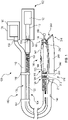
- FIG. 1 illustrates a flexible shaft rotary tool 100 having a motor housing 102, a flexible drive transmission shaft 104, a handpiece 106, and a dust collection system 108.
- the motor housing 102 includes an electric motor 110 (illustrated schematically), which is coupled to an axially-oriented drive shaft 112 having a noncircular recess 114 configured to couple with a noncircular and preferably square or rectangular-shaped drive shaft element 120 of the flexible drive shaft 104.
- the motor housing 102 is configured to hang on a movable rack or cart, while in other embodiments, the motor housing 102 is mounted to a wall or other fixed structure. In still further embodiments, the motor housing 102 is formed by an exterior housing of a conventional battery-powered or corded rotary tool having an internal motor, and the flexible shaft 104 attaches to the accessory tool holder of the conventional rotary tool.
- the flexible shaft 104 includes the drive shaft element 120, which is rotatable within, and circumscribed by a sheath or casing 122, and a coil support (not shown) disposed between the drive shaft element 120 and the casing 122.
- the drive shaft element 120 is formed of flexible metal and the casing 122 is formed durable, inexpensive, thermoformable plastic material such as polyvinylchloride (PVC). In other embodiments, however, other desired materials are used for the drive shaft element 120 and the casing 122.
- Coiled, spring-like bend protectors 124, 126 are respectively located at opposite ends of the flexible shaft 104 to protect the flexible shaft 104 against sharp bends or kinks.
- connection between the flexible shaft 104 and the motor housing 102 is separable by a user without additional tools.
- the motor housing 102 or the flexible shaft 104 includes a quick-disconnect system configured to enable easy removal of the flexible shaft 104 from the motor housing 102.
- the bend protector 126 engages a first end 140 of a handpiece housing 142 of the handpiece 106.
- the handpiece 106 also includes a driven shaft 144 arranged in the handpiece housing 142.
- the driven shaft 144 is rotationally fixed to the handpiece end 130 of the drive shaft element 120 and extends to a second, working end 146 of the handpiece 106.
- the drive shaft element 120 drives the driven shaft 144 to rotate a bit holder 148, in which a working attachment or tool bit 150, such as, for example, a drill bit, a polishing disk, a grinding wheel, a sanding wheel, a cutting wheel or bit, a wire brush, a saw or other rotary tool attachment, is fixed.
- the dust collection system 108 includes a vacuum housing 170, a connecting hose 172, and a nozzle portion 174.
- the vacuum housing 170 encloses a vacuum blower 180, which includes a motor (not shown) operatively connected to a fan (not shown) that produces a negative pressure in an outlet connector 182 that is attached to the connecting hose 172.
- the vacuum housing 170 is a separate housing from the motor housing 102.
- the vacuum housing 170 may be a conventional mobile or fixed workshop vacuum to which the connecting hose 172 is removably attached via the outlet connector 182.
- the vacuum housing 170 is configured for use specifically with the connecting hose 172, and may be fixedly connected to the connecting hose 172 via the outlet connector 182.
- the outlet connector is connected to a larger vacuum hose (not shown), which is connected via a hose adapter to the connecting hose 172.
- the vacuum housing 170 and the motor housing 102 are integrated with one another, such that a single housing encloses both the electric motor 110 and the vacuum blower 180.
- the electric motor 110 is operatively connected to the vacuum blower 180 and rotates the fan of the vacuum blower 180 to generate the negative pressure in the outlet connector 182.
- the dust collection system does not include a separate vacuum motor.
- the connecting hose 172 is flexible and extends along the flexible shaft 104 from the vacuum housing 170 to the nozzle portion 174.
- the interior of the connecting hose 172 defines a void region 178 that is fluidly connected to the outlet connector 182 of the vacuum housing 170 such that the negative pressure in the outlet connector 182 is also present in the void region 178.
- the connecting hose 172 is approximately one inch in diameter, though other desired hose sizes are used in other embodiments.
- the connecting hose 172 includes a plurality of ribs 184 separated from one another by a plurality of recesses 186 to facilitate the expansion, contraction, and flexibility of the connecting hose 172.
- the dust collection system 108 further includes a plurality of clips 188, 190 spaced along the length of the connecting hose 172.
- the clips 188, 190 are connected to and extend at least partially around both the connecting hose 172 and the flexible shaft 104 so as to attach the connecting hose 172 to the flexible shaft 104 and maintain the connecting hose 172 adjacent to the flexible shaft 104 along a length of the flexible shaft 104.
- the connecting hose 172 is adjacent to the flexible shaft 104 along the entire length of the flexible shaft 104. In one particular embodiment, the connecting hose 172 is adjacent to the flexible shaft 104 along approximately 90% of the entire length of the flexible shaft 104. In another embodiment, the connecting hose is adjacent to the flexible shaft 104 along approximately 75% of the entire length of the flexible shaft 104.
- the clips 188 illustrated in FIG. 1 extend entirely around a portion of both the flexible shaft 104 and the connecting hose 172.
- the clips 188 may be configured to extend only around a portion of each of the flexible shaft 104 and the connecting hose, similar to clip 190 described below, to facilitate easy disconnecting of the flexible shaft 104 from the connecting hose 172.
- the clip 190 includes a first portion 192 connected to the connecting hose 172 and a second portion 194 connected to the flexible shaft 104.
- the first portion 192 is formed generally in the shape of a semicircle having an inner diameter that is approximately equal to the outer diameter of the connecting hose 172.
- the first portion 192 further includes a plurality of projections 196 extending radially inwardly into the recesses 186 of the connecting hose 172 so as to connect the first portion 192 to the connecting hose 172.
- the second portion 194 of the clip 190 is formed generally as a semicircle having an inner diameter that is approximately equal to the outer diameter of the casing 122 of the flexible shaft 104.
- the second portion 194 of the clip 190 is prestressed so as to exert a holding force on the casing 122 to retain the clip 190 connected to the casing 122. Since the clip 190 is not positively connected to either the flexible shaft 104 or the connecting hose 172, the user can easily disconnect the connecting hose 172 from the flexible shaft 104.
- the dust collection system 108 further includes an adapter clip 200 at the interface between the connecting hose 172 and the nozzle portion 174.
- the adapter clip 200 includes a first portion 202 and a second portion 204, each of which has a generally annular cross-section.
- the first portion 202 defines a cylindrical cavity 206, in which the connecting hose 172 is received.
- the first portion 202 includes one or more projections (not shown) extending radially inwardly from the inner wall into one or more of the recesses 186 to engage one or more of the ribs 184 of the connecting hose 172 to retain the connecting hose 172 fixed to the adapter clip 200.
- the second portion 204 projects into the interior of the nozzle body 240 (discussed in detail below) of the nozzle portion 174 of the dust collection system 108.
- the inner wall of the nozzle body 240 engages the outer wall of the second portion 204 of the adapter clip 200 so as to retain the nozzle body 240 in connection with the second portion 204 of the adapter clip 200 in a form fitting connection.
- the adapter clip 200 is locked with, clamped to, integrated with, or otherwise suitable connected to the nozzle body 240.
- the adapter clip also 200 also includes two clip projections 210, 212 extending in a direction generally toward the flexible shaft 104, substantially perpendicular to the central axis of the adapter clip.
- the clip projections 210, 212 each have an arcuate shape with a raised feature 214, for example a bump, near the free end of the clip projections 210, 212.
- the raised features 214 on each side of the clip projections 210, 212 are configured to releasably clamp the casing 122 of the flexible shaft 104 to the adapter clip 200, thereby retaining the flexible shaft 104 adjacent to the connecting hose 172.
- the nozzle portion 174 of the dust collection system 108 includes the nozzle body 240, which is attached at a first end portion 242 to the second portion 204 of the adapter clip 200.
- the interior of the nozzle body 240 defines a nozzle void region 244 ( FIG. 3 ), which is fluidly connected to the hose void region 178 of the connecting hose 172 in such a way that the negative pressure in the hose void region 178 is also present in the nozzle void region 244.
- the second end portion 246 of the nozzle body 240 defines a nozzle opening 248, through which dust and debris is pulled from the area adjacent the tool bit 150 to the nozzle void region 244.
- the nozzle opening 248 is shaped as a circular opening, an angled circular opening (illustrated in FIGS. 1 , 2 , and 4 ), a tapering opening, a slotted opening, an arcuate opening, an annular opening, or any other desired opening size and shape.
- the nozzle body 240 also includes an attachment member 250 extending around the working end 146 of the handpiece 140.
- the attachment member 250 projects around the working end 146 of the handpiece 140, defining an opening 252 surrounding a portion of the working end 146.
- the attachment member 250 includes at least one screw thread 254, which is configured to matingly connect to screw threads 256 on the working end 146 of the handpiece 140.
- the attachment member 250 is attached to a grip portion of the handpiece 140.
- the suction produced by the vacuum blower 180 pulls dust and debris machined from the workpiece through the nozzle opening 248, through the void region 244 of the nozzle body 240, the void region 178 of the connecting hose 172, and to the vacuum 172 where the dust is stored for subsequent disposal.
- Providing the nozzle opening 258 adjacent the tool bit 150 enables the vacuum pressure to pull dust and debris from the workpiece as the dust and debris is produced, keeping the work area clean and avoiding obscuring the user's view of the details of the workpiece.
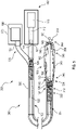
- FIG. 5 illustrates another embodiment of a rotary tool 300 having a dust collection system 308.
- the rotary tool 300 includes a motor housing 102, a flexible shaft 104, and a handpiece 106 configured similarly to the rotary tool 100 described above.
- the dust collection system 308 of the embodiment of FIG. 5 includes a vacuum motor housing 170, a connecting hose 320, and a nozzle portion 324.
- the vacuum motor housing 170 is configured in substantially the same manner as in the embodiment of FIGS. 1-4 , with a vacuum blower 180 configured to produce suction in the outlet connector 182.
- the vacuum blower 180 is integrated in the motor housing 120, and the vacuum connector 182 is positioned so as to connect around the outer circumference of the drive shaft element 120 of the flexible shaft 104.
- the connecting hose 320 includes a first end 330 connected to the vacuum connector 182 and a second end 332 connected to the nozzle portion 324.
- the connecting hose 320 surrounds the flexible shaft 104 along the length of the flexible shaft 104.
- the connecting hose 320 is formed by a plurality of ribs or projections (not shown), each of which is separated from adjacent projections by a recess (not shown), similar to the embodiment shown in FIGS. 2 and 3 , so as to facilitate movement, expansion, and contraction of the connecting hose 320.
- the interior of the connecting hose 320 defines a void region 334 having a generally annular cross-sectional shape surrounding the flexible shaft 104.
- the void region 334 is fluidly connected to the vacuum connector 182 within the connecting hose 320 in such a way that the negative pressure from the vacuum connector 182 also exists in the void region 334.
- the connecting hose 320 is attached to the nozzle portion 324 of the dust collection system 308.
- the nozzle portion 324 includes a nozzle body 340, which has a first end 342 adjacent the connecting hose 320 and a second end 344, or working end, opposite the connecting hose 320.
- the nozzle body 340 has a first portion 346 that has a diameter that expands outwardly moving from the first end 342 of the nozzle body in a direction toward the second end 344.
- a second portion 348 of the nozzle body 340 has a diameter that decreases moving from the first portion 346 toward the second end 344.
- the shape of the nozzle body 340 generally conforms to the outer shape of the handpiece housing 142.
- a nozzle void region 350 is defined between the inner wall of the nozzle body 340 and the outer surface of the handpiece housing 142.
- the nozzle void region 350 is fluidly connected to the void region 344 of the connecting hose 320 such that the negative pressure in the connecting hose void region 344 is also present in the nozzle void region 350.
- the nozzle body 340 defines a dust collection opening 354 surrounding a portion of the bit holder 148 or the tool bit 150.
- the negative pressure present in the nozzle void region 350 pulls air, dust, and debris in the vicinity of the tool bit 150 into the dust collection opening 354, where the air, dust, and debris is transferred through the nozzle void region 350 and the connecting hose void region 344 and vacuum connector 182 to the vacuum housing 170, where the dust and debris is stored for subsequent disposal.
- the dust collection system 308 of the rotary tool 300 therefore enables dust and debris to be removed from the area of the tool bit 150, thereby providing a cleaner work area while the user is using the rotary tool 300 and reducing the cleaning required after use of the rotary tool 300.
- FIGS. 6 and 7 illustrate two other embodiments of connecting hoses for use in place of the connecting hoses 172, 320 in the embodiments described above.
- the embodiment of FIG. 6 shows a connecting hose 410 having a plurality of segments 420, each of which includes a widened receiving portion 422 and a smaller recessed portion 424.
- the recessed portion 424 of each segment 420 is positioned in the receiving portion 422 of the adjacent segment 420 in such a way that the segments 420 articulate relative to one another.
- the connecting hose 410 is movable so as to remain adjacent to or surrounding the flexible shaft 104.
- FIG. 7 is a connecting hose 430 having a metal sheath 434 with a plurality of short metal segments 438.
- Each of the metal segments 438 articulates relative to the adjacent segments 438 so that the entire connecting hose 430 is flexible.
- the metal sheath 434 is formed of a flexible metal to provide additional mobility for the connecting hose 430.
Landscapes
- Engineering & Computer Science (AREA)
- Mechanical Engineering (AREA)
- Auxiliary Devices For Machine Tools (AREA)
- Grinding-Machine Dressing And Accessory Apparatuses (AREA)
- Cleaning In General (AREA)
Description
- This disclosure relates generally to power tools, and more particularly to dust collection systems for rotary power tools.
- In general, rotary power tools are light-weight, handheld power tools capable of being equipped with a variety of accessory tools and attachments, such as cutting blades, sanding discs, grinding tools, and many others. These types of tools typically include a generally cylindrically-shaped main body that serves as an enclosure for an electric motor as well as a hand grip for the tool. The electric motor drives an output shaft to rotate at high speeds. The output shaft is equipped with an accessory attachment system that enables accessory tools to be releasably secured to the power tool.
- In some rotary tools, known as "flexible-shaft" rotary tools, the motor is located in a motor housing separate from the body of the tool. The motor enclosure is attached to the main body of the tool via a flexible shaft, which includes a plurality of rotatable components that transmit the rotational motion generated by the motor to the output shaft of the rotary tool. For example,
EP 1 338 386 A2 describes a rotary power tool having a flexible shaft transmission shaft. An abrading tool having a flexible shaft is further disclosed inUS 5 795 216 A . The preamble of claim 1 is based on this document, wherein the handpiece housing acts at the same time as nozzle portion. -
US 7 014 546 B1 describes a sanding apparatus with a sanding unit being coupled to the end of a flexible drive shaft and includes a vacuum socket coupled to a vacuum via a vacuum hose. The vacuum hose is attached to the drive shaft. - Due to the light weight of the tool body of flexible-shaft rotary tools, these tools are frequently used for carving. However, when carving or machining, the rotary tools produce dust and debris that the user has to constantly remove from the area of the workpiece being machined so as to not obscure the details being carved. In addition, the dust and debris leaves the work area dirty and can cause problems for respiration of the user. It would therefore be beneficial to provide a flexible-shaft rotary tool that reduces the dust and debris produced during machining.
- In one example, a dust collection system for a rotary power tool, which has a flexible shaft connected to a handpiece, includes a vacuum blower configured to generate a negative pressure and a connecting hose defining a first void region fluidly connected to the blower and which has the negative pressure. The connecting hose is configured to extend along a first length of the flexible shaft. The dust collection system further comprises a nozzle portion defining a second void region fluidly connected to the first void region and which has the negative pressure, the nozzle portion being configured to extend along a second length of the handpiece.
- In some examples of the dust collection system, the nozzle portion includes a nozzle body defining the second void region and an opening adjacent to a bit holder of the handpiece, the opening being fluidly connected to the second void region and having the negative pressure.
- In another example, the nozzle body includes an attachment member configured to connect the nozzle body to the handpiece, and the attachment member includes a threaded portion configured to engage a corresponding threaded portion of the handpiece.
- In yet another example, the connecting hose radially surrounds the first length of the flexible shaft and the first void region is defined radially between the flexible shaft and the connecting hose. In such an example, the volume occupied by the connecting hose and the flexible shaft is advantageously reduced since the flexible hose is located within the connecting hose.
- In a further example, the nozzle portion includes a nozzle body enclosing the second length of the handpiece, the second void region being defined between the handpiece and the nozzle body.
- In another example, the nozzle body defines an opening configured to surround a portion of a tool bit holder of the handpiece, the opening being fluidly connected to the second void region and having the negative pressure.
- In one example, of the dust collection system further comprises a plurality of clips configured to connect the connecting hose to the flexible shaft along the first length of the flexible shaft.
- In yet another example, the dust collection system further comprises an adapter clip interposed between the connecting hose and a nozzle body of the nozzle portion, the adapter clip including at least one clip projection extending from a first portion of the adapter clip. The at least one clip projection being configured to receive the flexible shaft and releasably retain the flexible shaft.
- In a further example of the dust collection system, the first portion has an inner circumferential surface that engages the connecting hose and the adapter clip includes a second portion having an outer circumferential surface that engages an inner wall of the nozzle portion.
- In some examples, the clip projection includes a fixed end at the first portion and a free end opposite the fixed end, the free end including a raised feature configured to engage the flexible shaft.
- The invention provides a rotary power tool in accordance with claim 1.
- According to the invention, a rotary power tool comprises a motor configured to rotate an output shaft, a flexible shaft including a first end operably connected to the output shaft so as to rotate with the output shaft, and a handpiece including a bit holder configured to receive a tool bit, the bit holder being operatively connected to a second end of the flexible shaft so as to rotate with the flexible shaft. The rotary power tool further includes a dust collection system comprising a vacuum blower configured to generate a negative pressure and a connecting hose defining a first void region fluidly connected to the blower and which has the negative pressure, the connecting hose extending along a first length of the flexible shaft. The connecting hose radially surrounds the first length of the flexible shaft and the first void region is defined radially between the flexible shaft and the connecting hose. The dust collection system further comprises a nozzle portion defining a second void region fluidly connected to the first void region and which has the negative pressure, the nozzle portion extending along a second length of the handpiece. The nozzle portion includes a nozzle body enclosing the second length of the handpiece, wherein the nozzle body has a first end adjacent the connecting hose and a second end opposite the connecting hose, and wherein the second void region is defined between an inner wall of the nozzle body and an outer surface of the handpiece housing.
- In one example of the rotary power tool, the nozzle portion includes a nozzle body defining the second void region and defining an opening adjacent to the bit holder. The opening is fluidly connected to the second void region and has the negative pressure.
- In yet another example, the nozzle body includes an attachment member connecting the nozzle body to the handpiece, the attachment member including a threaded opening engaging a corresponding threaded portion of the handpiece.
- In one embodiment of the invention, the nozzle body defines an opening arranged surrounding a portion of the bit holder, and the opening is fluidly connected to the second void region and having the negative pressure.
- Some examples of the rotary power tool further comprise a plurality of clips connecting the connecting hose to the flexible shaft along the first length of the flexible shaft.
- In yet another example, the dust collection system further comprises an adapter clip interposed between the connecting hose and a nozzle body of the nozzle portion. The adapter clip includes at least one clip projection extending from a first portion of the adapter clip and which releasably retains the flexible shaft.
- In one example of the rotary power tool, the first portion of the adapter clip has an inner circumferential surface that engages the connecting hose, and the adapter clip includes a second portion having an outer circumferential surface that engages an inner wall of the nozzle portion.
- In some examples of the rotary power tool, the clip projection includes a fixed end at the first portion and a free end opposite the fixed end, the free end including a raised feature that engages the flexible shaft.
-
-
FIG. 1 is a schematic partial cutaway view of a flexible-shaft rotary tool having a dust collection system according to an embodiment forming not part of the invention. -
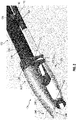
FIG. 2 is a side perspective detail view of the nozzle portion of the dust collection system and the handpiece of the rotary tool ofFIG. 1 . -
FIG. 3 is a cross-sectional view of an adapter clip connecting the connecting hose to the nozzle body of the dust collection system ofFIG. 1 . -
FIG. 4 is a cross-sectional view of the nozzle body having an attachment member according to an embodiment forming not part of the invention. -
FIG. 5 is a schematic partial cutaway view of a flexible-shaft rotary tool having another dust collection system according to an embodiment of the invention. -
FIG. 6 is a side view of a connecting hose for use in the dust collection systems ofFIG. 1 orFIG. 5 . -
FIG. 7 is a side view of another connecting hose for use in the dust collection systems ofFIG. 1 orFIG. 5 . - For the purposes of promoting an understanding of the principles of the embodiments described herein, reference is now made to the drawings and descriptions in the following written specification. No limitation to the scope of the subject matter is intended by the references. This disclosure also includes any alterations and modifications to the illustrated embodiments and includes further applications of the principles of the described embodiments as would normally occur to one skilled in the art to which this document pertains.
- As used herein, the term "approximately" is defined to refer to values within five percent less than or greater than the given value. As used herein, the term "adjacent" is defined to refer to two structures or elements that are located within one inch from one another.
-
FIG. 1 illustrates a flexibleshaft rotary tool 100 having amotor housing 102, a flexibledrive transmission shaft 104, ahandpiece 106, and adust collection system 108. Themotor housing 102 includes an electric motor 110 (illustrated schematically), which is coupled to an axially-orienteddrive shaft 112 having anoncircular recess 114 configured to couple with a noncircular and preferably square or rectangular-shapeddrive shaft element 120 of theflexible drive shaft 104. - In some embodiments, the
motor housing 102 is configured to hang on a movable rack or cart, while in other embodiments, themotor housing 102 is mounted to a wall or other fixed structure. In still further embodiments, themotor housing 102 is formed by an exterior housing of a conventional battery-powered or corded rotary tool having an internal motor, and theflexible shaft 104 attaches to the accessory tool holder of the conventional rotary tool. - The
flexible shaft 104 includes thedrive shaft element 120, which is rotatable within, and circumscribed by a sheath orcasing 122, and a coil support (not shown) disposed between thedrive shaft element 120 and thecasing 122. In one embodiment, thedrive shaft element 120 is formed of flexible metal and thecasing 122 is formed durable, inexpensive, thermoformable plastic material such as polyvinylchloride (PVC). In other embodiments, however, other desired materials are used for thedrive shaft element 120 and thecasing 122. Coiled, spring-like bend protectors flexible shaft 104 to protect theflexible shaft 104 against sharp bends or kinks. In some embodiments, the connection between theflexible shaft 104 and themotor housing 102 is separable by a user without additional tools. In one particular embodiment, themotor housing 102 or theflexible shaft 104 includes a quick-disconnect system configured to enable easy removal of theflexible shaft 104 from themotor housing 102. - At the
handpiece end 128 of theflexible shaft 104, thebend protector 126 engages afirst end 140 of ahandpiece housing 142 of thehandpiece 106. Thehandpiece 106 also includes a drivenshaft 144 arranged in thehandpiece housing 142. The drivenshaft 144 is rotationally fixed to thehandpiece end 130 of thedrive shaft element 120 and extends to a second, workingend 146 of thehandpiece 106. Thedrive shaft element 120 drives the drivenshaft 144 to rotate abit holder 148, in which a working attachment ortool bit 150, such as, for example, a drill bit, a polishing disk, a grinding wheel, a sanding wheel, a cutting wheel or bit, a wire brush, a saw or other rotary tool attachment, is fixed. - The
dust collection system 108 includes avacuum housing 170, a connectinghose 172, and anozzle portion 174. Thevacuum housing 170 encloses avacuum blower 180, which includes a motor (not shown) operatively connected to a fan (not shown) that produces a negative pressure in anoutlet connector 182 that is attached to the connectinghose 172. - In the illustrated embodiment, the
vacuum housing 170 is a separate housing from themotor housing 102. For example, in one embodiment, thevacuum housing 170 may be a conventional mobile or fixed workshop vacuum to which the connectinghose 172 is removably attached via theoutlet connector 182. In another embodiment, thevacuum housing 170 is configured for use specifically with the connectinghose 172, and may be fixedly connected to the connectinghose 172 via theoutlet connector 182. In one embodiment, the outlet connector is connected to a larger vacuum hose (not shown), which is connected via a hose adapter to the connectinghose 172. - In another embodiment, the
vacuum housing 170 and themotor housing 102 are integrated with one another, such that a single housing encloses both theelectric motor 110 and thevacuum blower 180. In a further embodiment, theelectric motor 110 is operatively connected to thevacuum blower 180 and rotates the fan of thevacuum blower 180 to generate the negative pressure in theoutlet connector 182. In such an embodiment, the dust collection system does not include a separate vacuum motor. - The connecting
hose 172 is flexible and extends along theflexible shaft 104 from thevacuum housing 170 to thenozzle portion 174. The interior of the connectinghose 172 defines avoid region 178 that is fluidly connected to theoutlet connector 182 of thevacuum housing 170 such that the negative pressure in theoutlet connector 182 is also present in thevoid region 178. In one embodiment, the connectinghose 172 is approximately one inch in diameter, though other desired hose sizes are used in other embodiments. As illustrated inFIG. 2 , in some embodiments, the connectinghose 172 includes a plurality ofribs 184 separated from one another by a plurality ofrecesses 186 to facilitate the expansion, contraction, and flexibility of the connectinghose 172. - The
dust collection system 108 further includes a plurality ofclips hose 172. Theclips hose 172 and theflexible shaft 104 so as to attach the connectinghose 172 to theflexible shaft 104 and maintain the connectinghose 172 adjacent to theflexible shaft 104 along a length of theflexible shaft 104. - In some embodiments, the connecting
hose 172 is adjacent to theflexible shaft 104 along the entire length of theflexible shaft 104. In one particular embodiment, the connectinghose 172 is adjacent to theflexible shaft 104 along approximately 90% of the entire length of theflexible shaft 104. In another embodiment, the connecting hose is adjacent to theflexible shaft 104 along approximately 75% of the entire length of theflexible shaft 104. - The
clips 188 illustrated inFIG. 1 extend entirely around a portion of both theflexible shaft 104 and the connectinghose 172. In some embodiments, theclips 188 may be configured to extend only around a portion of each of theflexible shaft 104 and the connecting hose, similar to clip 190 described below, to facilitate easy disconnecting of theflexible shaft 104 from the connectinghose 172. - A detailed view of the
clip 190 is seen inFIG. 2 attached near thehandpiece end 128 of theflexible shaft 104. Theclip 190 includes afirst portion 192 connected to the connectinghose 172 and asecond portion 194 connected to theflexible shaft 104. Thefirst portion 192 is formed generally in the shape of a semicircle having an inner diameter that is approximately equal to the outer diameter of the connectinghose 172. Thefirst portion 192 further includes a plurality ofprojections 196 extending radially inwardly into therecesses 186 of the connectinghose 172 so as to connect thefirst portion 192 to the connectinghose 172. - The
second portion 194 of theclip 190 is formed generally as a semicircle having an inner diameter that is approximately equal to the outer diameter of thecasing 122 of theflexible shaft 104. In the illustrated embodiment, thesecond portion 194 of theclip 190 is prestressed so as to exert a holding force on thecasing 122 to retain theclip 190 connected to thecasing 122. Since theclip 190 is not positively connected to either theflexible shaft 104 or the connectinghose 172, the user can easily disconnect the connectinghose 172 from theflexible shaft 104. - The
dust collection system 108 further includes anadapter clip 200 at the interface between the connectinghose 172 and thenozzle portion 174. With continued reference toFIG. 2 and further reference toFIG. 3 , theadapter clip 200 includes afirst portion 202 and asecond portion 204, each of which has a generally annular cross-section. Thefirst portion 202 defines a cylindrical cavity 206, in which the connectinghose 172 is received. In some embodiments, thefirst portion 202 includes one or more projections (not shown) extending radially inwardly from the inner wall into one or more of therecesses 186 to engage one or more of theribs 184 of the connectinghose 172 to retain the connectinghose 172 fixed to theadapter clip 200. - The
second portion 204 projects into the interior of the nozzle body 240 (discussed in detail below) of thenozzle portion 174 of thedust collection system 108. The inner wall of thenozzle body 240 engages the outer wall of thesecond portion 204 of theadapter clip 200 so as to retain thenozzle body 240 in connection with thesecond portion 204 of theadapter clip 200 in a form fitting connection. The reader should appreciate, however, that in other embodiments theadapter clip 200 is locked with, clamped to, integrated with, or otherwise suitable connected to thenozzle body 240. - The adapter clip also 200 also includes two
clip projections flexible shaft 104, substantially perpendicular to the central axis of the adapter clip. Theclip projections feature 214, for example a bump, near the free end of theclip projections clip projections casing 122 of theflexible shaft 104 to theadapter clip 200, thereby retaining theflexible shaft 104 adjacent to the connectinghose 172. - The
nozzle portion 174 of thedust collection system 108 includes thenozzle body 240, which is attached at afirst end portion 242 to thesecond portion 204 of theadapter clip 200. The interior of thenozzle body 240 defines a nozzle void region 244 (FIG. 3 ), which is fluidly connected to thehose void region 178 of the connectinghose 172 in such a way that the negative pressure in thehose void region 178 is also present in thenozzle void region 244. Thesecond end portion 246 of thenozzle body 240 defines anozzle opening 248, through which dust and debris is pulled from the area adjacent thetool bit 150 to thenozzle void region 244. In various embodiments of thenozzle body 240, thenozzle opening 248 is shaped as a circular opening, an angled circular opening (illustrated inFIGS. 1 ,2 , and4 ), a tapering opening, a slotted opening, an arcuate opening, an annular opening, or any other desired opening size and shape. - Referring now to
FIGS. 2 and4 , at thesecond end portion 246, thenozzle body 240 also includes anattachment member 250 extending around the workingend 146 of thehandpiece 140. Theattachment member 250 projects around the workingend 146 of thehandpiece 140, defining anopening 252 surrounding a portion of the workingend 146. In one embodiment, theattachment member 250 includes at least onescrew thread 254, which is configured to matingly connect to screwthreads 256 on the workingend 146 of thehandpiece 140. In another embodiment, theattachment member 250 is attached to a grip portion of thehandpiece 140. - In use, the suction produced by the
vacuum blower 180 pulls dust and debris machined from the workpiece through thenozzle opening 248, through thevoid region 244 of thenozzle body 240, thevoid region 178 of the connectinghose 172, and to thevacuum 172 where the dust is stored for subsequent disposal. Providing the nozzle opening 258 adjacent thetool bit 150 enables the vacuum pressure to pull dust and debris from the workpiece as the dust and debris is produced, keeping the work area clean and avoiding obscuring the user's view of the details of the workpiece. -
FIG. 5 illustrates another embodiment of arotary tool 300 having adust collection system 308. Therotary tool 300 includes amotor housing 102, aflexible shaft 104, and ahandpiece 106 configured similarly to therotary tool 100 described above. In addition, similarly to the embodiment ofFIGS. 1-4 , thedust collection system 308 of the embodiment ofFIG. 5 includes avacuum motor housing 170, a connectinghose 320, and anozzle portion 324. Thevacuum motor housing 170 is configured in substantially the same manner as in the embodiment ofFIGS. 1-4 , with avacuum blower 180 configured to produce suction in theoutlet connector 182. In one embodiment, thevacuum blower 180 is integrated in themotor housing 120, and thevacuum connector 182 is positioned so as to connect around the outer circumference of thedrive shaft element 120 of theflexible shaft 104. - The connecting
hose 320 includes a first end 330 connected to thevacuum connector 182 and asecond end 332 connected to thenozzle portion 324. The connectinghose 320 surrounds theflexible shaft 104 along the length of theflexible shaft 104. In some embodiments, the connectinghose 320 is formed by a plurality of ribs or projections (not shown), each of which is separated from adjacent projections by a recess (not shown), similar to the embodiment shown inFIGS. 2 and3 , so as to facilitate movement, expansion, and contraction of the connectinghose 320. - The interior of the connecting
hose 320 defines avoid region 334 having a generally annular cross-sectional shape surrounding theflexible shaft 104. Thevoid region 334 is fluidly connected to thevacuum connector 182 within the connectinghose 320 in such a way that the negative pressure from thevacuum connector 182 also exists in thevoid region 334. - At the
second end 332, the connectinghose 320 is attached to thenozzle portion 324 of thedust collection system 308. Thenozzle portion 324 includes anozzle body 340, which has afirst end 342 adjacent the connectinghose 320 and asecond end 344, or working end, opposite the connectinghose 320. In the illustrated embodiment, thenozzle body 340 has afirst portion 346 that has a diameter that expands outwardly moving from thefirst end 342 of the nozzle body in a direction toward thesecond end 344. Asecond portion 348 of thenozzle body 340 has a diameter that decreases moving from thefirst portion 346 toward thesecond end 344. As a result, the shape of thenozzle body 340 generally conforms to the outer shape of thehandpiece housing 142. Anozzle void region 350 is defined between the inner wall of thenozzle body 340 and the outer surface of thehandpiece housing 142. Thenozzle void region 350 is fluidly connected to thevoid region 344 of the connectinghose 320 such that the negative pressure in the connecting hosevoid region 344 is also present in thenozzle void region 350. - At the
second end 344, thenozzle body 340 defines adust collection opening 354 surrounding a portion of thebit holder 148 or thetool bit 150. The negative pressure present in thenozzle void region 350 pulls air, dust, and debris in the vicinity of thetool bit 150 into thedust collection opening 354, where the air, dust, and debris is transferred through thenozzle void region 350 and the connecting hosevoid region 344 andvacuum connector 182 to thevacuum housing 170, where the dust and debris is stored for subsequent disposal. Thedust collection system 308 of therotary tool 300 therefore enables dust and debris to be removed from the area of thetool bit 150, thereby providing a cleaner work area while the user is using therotary tool 300 and reducing the cleaning required after use of therotary tool 300. -
FIGS. 6 and 7 illustrate two other embodiments of connecting hoses for use in place of the connectinghoses FIG. 6 shows a connectinghose 410 having a plurality ofsegments 420, each of which includes a widened receivingportion 422 and a smaller recessedportion 424. The recessedportion 424 of eachsegment 420 is positioned in the receivingportion 422 of theadjacent segment 420 in such a way that thesegments 420 articulate relative to one another. Thus, the connectinghose 410 is movable so as to remain adjacent to or surrounding theflexible shaft 104. - The embodiment of
FIG. 7 is a connectinghose 430 having ametal sheath 434 with a plurality ofshort metal segments 438. Each of themetal segments 438 articulates relative to theadjacent segments 438 so that the entire connectinghose 430 is flexible. In some embodiments, themetal sheath 434 is formed of a flexible metal to provide additional mobility for the connectinghose 430. - It will be appreciated that variants of the above-described and other features and functions, or alternatives thereof, may be desirably combined into many other different systems, applications or methods. Various presently unforeseen or unanticipated alternatives, modifications, variations or improvements may be subsequently made by those skilled in the art that are also intended to be encompassed by the foregoing disclosure.
Claims (2)
- A rotary power tool (300) comprising:a motor (110) configured to rotate an output shaft (112);a flexible shaft (104) including a first end (120) operably connected to the output shaft (112) so as to rotate with the output shaft (112);a handpiece (106) including a handpiece housing (142), a driven shaft (144) arranged in the handpiece housing (142) and rotationally fixed to a second end (130) of the flexible shaft (104) so as to rotate with the flexible shaft (104), and a bit holder (148) configured to receive a tool bit, the bit holder (148) being operatively connected to the flexible shaft (104) by the driven shaft (144) so as to rotate with the flexible shaft (104); anda dust collection system (108) comprising:a vacuum blower (180) configured to generate a negative pressure;a connecting hose (320) defining a first void (334) region fluidly connected to the blower (180) and which has the negative pressure, the connecting hose (320) extending along a first length of the flexible shaft (104), wherein the connecting hose (320) radially surrounds the first length of the flexible shaft (104), and wherein the first void region (334) is defined radially between the flexible shaft (104) and the connecting hose (320);characterized in comprisinga nozzle portion (324) defining a second void region (350) fluidly connected to the first void region (334) and which has the negative pressure, the nozzle portion (324) extending along a second length of the handpiece (106), wherein the nozzle portion (324) includes a nozzle body (340) enclosing the second length of the handpiece (106), wherein the nozzle body (340) has a first end (342) adjacent the connecting hose (320) and a second end (344) opposite the connecting hose (320), and wherein the second void region (350) is defined between an inner wall of the nozzle body (340) and an outer surface of the handpiece housing (142).
- The rotary power tool (300) of claim 1, wherein the nozzle body (340) defines an opening (354) arranged surrounding a portion of the bit holder (148), the opening (354) being fluidly connected to the second void region (350) and having the negative pressure.
Applications Claiming Priority (2)
| Application Number | Priority Date | Filing Date | Title |
|---|---|---|---|
| US15/227,771 US10493579B2 (en) | 2016-08-03 | 2016-08-03 | Dust collection system for a rotary power tool |
| PCT/EP2017/068597 WO2018024523A1 (en) | 2016-08-03 | 2017-07-24 | Dust collection system for a rotary power tool |
Publications (2)
| Publication Number | Publication Date |
|---|---|
| EP3493947A1 EP3493947A1 (en) | 2019-06-12 |
| EP3493947B1 true EP3493947B1 (en) | 2022-12-07 |
Family
ID=59558389
Family Applications (1)
| Application Number | Title | Priority Date | Filing Date |
|---|---|---|---|
| EP17749152.9A Active EP3493947B1 (en) | 2016-08-03 | 2017-07-24 | Rotary power tool with a dust collection system |
Country Status (3)
| Country | Link |
|---|---|
| US (1) | US10493579B2 (en) |
| EP (1) | EP3493947B1 (en) |
| WO (1) | WO2018024523A1 (en) |
Families Citing this family (14)
| Publication number | Priority date | Publication date | Assignee | Title |
|---|---|---|---|---|
| US9776296B2 (en) | 2008-05-09 | 2017-10-03 | Milwaukee Electric Tool Corporation | Power tool dust collector |
| JP6758853B2 (en) * | 2016-02-22 | 2020-09-23 | 株式会社マキタ | Angle tool |
| KR101953987B1 (en) * | 2017-08-30 | 2019-03-04 | 두산중공업 주식회사 | Nozzle cutting device in reactor vessel |
| CN112873136B (en) * | 2019-12-01 | 2026-02-03 | 南京泉峰科技有限公司 | Power tool system |
| WO2021109888A1 (en) * | 2019-12-01 | 2021-06-10 | 南京德朔实业有限公司 | Electric power tool system |
| EP4073414A4 (en) * | 2019-12-13 | 2023-12-27 | Envirochasing IP Holdings Pty Ltd | COUPLING |
| US11691259B2 (en) | 2020-05-18 | 2023-07-04 | Techtronic Cordless Gp | Rotary tool |
| DE102020208392A1 (en) * | 2020-07-03 | 2022-01-05 | Robert Bosch Gesellschaft mit beschränkter Haftung | Suction attachment |
| CN111843592A (en) * | 2020-07-25 | 2020-10-30 | 广州优易机械科技有限公司 | Compound feed type numerically controlled lathe |
| CN114226351B (en) * | 2021-08-16 | 2024-01-30 | 重庆大学 | Complex multi-working-condition self-adaptive dust removing device for dry cutting processing of composite material |
| USD1064773S1 (en) | 2021-12-03 | 2025-03-04 | Robert Bosch Gmbh | Hammer drill |
| USD1034130S1 (en) * | 2022-02-07 | 2024-07-09 | Robert Bosch Gmbh | Suction attachment for a power tool |
| US20240238878A1 (en) * | 2023-01-13 | 2024-07-18 | The Boeing Company | Drilling apparatus |
| US20250277459A1 (en) * | 2024-02-29 | 2025-09-04 | Rtx Corporation | Cutting tool support for in-situ hole manufacturing |
Citations (1)
| Publication number | Priority date | Publication date | Assignee | Title |
|---|---|---|---|---|
| US5795216A (en) * | 1996-03-21 | 1998-08-18 | Dumont Companies | Abrading tool having a suction system for collecting abraded particles |
Family Cites Families (79)
| Publication number | Priority date | Publication date | Assignee | Title |
|---|---|---|---|---|
| GB1345341A (en) * | 1971-03-03 | 1974-01-30 | Devac Ab | Percussion machine |
| US3724561A (en) * | 1971-09-09 | 1973-04-03 | F Merrels | Multiple tool driving unit |
| DE2603330C2 (en) * | 1976-01-29 | 1986-09-04 | Norbert 6109 Mühltal Loevenich | Device for removing cuttings, drilling dust and the like, especially with hand drills during the drilling process |
| DE2705410C2 (en) * | 1977-02-09 | 1985-06-13 | Robert Bosch Gmbh, 7000 Stuttgart | Device for sucking off cuttings on a hand machine tool |
| US4124956A (en) * | 1977-07-22 | 1978-11-14 | Levinson Lewis R | Cutting system with debris vacuuming means |
| DE2744463C2 (en) * | 1977-10-03 | 1987-01-29 | Hilti Ag, Schaan | Suction attachment, especially for use with drilling equipment |
| US4215601A (en) * | 1979-03-16 | 1980-08-05 | Mann Steven R | Flexible shaft tool head |
| AU535542B2 (en) * | 1979-08-29 | 1984-03-29 | Nicholas Thomas Edward Dillon | Welding and cutting handpiece |
| US4330279A (en) * | 1980-01-07 | 1982-05-18 | American Hospital Supply Corporation | Fluid spray system for dental handpiece |
| DE3005860A1 (en) * | 1980-02-16 | 1981-09-03 | Robert Bosch Gmbh, 7000 Stuttgart | HAND MACHINE TOOL, ESPECIALLY TIN BEARING |
| EP0127380B1 (en) * | 1983-05-20 | 1988-10-12 | Micron Co., Ltd. | An endodontic irrigating instrument |
| US4574432A (en) * | 1983-12-27 | 1986-03-11 | Jacob Lionel C | Multi-purpose power tool |
| US4890779A (en) * | 1984-08-23 | 1990-01-02 | Giannuzzi Louis | Automatic setting tool for masonry anchors |
| US4722685A (en) * | 1985-05-30 | 1988-02-02 | Estrada Juan M De | Tool for adapting a portable lathe to treat the back molar teeth of horses |
| US4646738A (en) * | 1985-12-05 | 1987-03-03 | Concept, Inc. | Rotary surgical tool |
| US5025559A (en) * | 1987-09-29 | 1991-06-25 | Food Industry Equipment International, Inc. | Pneumatic control system for meat trimming knife |
| US4841643A (en) * | 1988-04-22 | 1989-06-27 | Colella Vincent J | Drill powered saber saw |
| GB8829182D0 (en) * | 1988-12-14 | 1989-01-25 | Univ Birmingham | Surgical instrument |
| US4989323A (en) * | 1989-06-05 | 1991-02-05 | Caspro Mechanical Technologies, Inc. | Portable power unit for various power tolls |
| IT1237154B (en) * | 1989-12-22 | 1993-05-24 | Black & Decker Italia | HANDLE WITH SUCTION HEAD FOR PORTABLE DRILL |
| US5034041A (en) * | 1990-06-26 | 1991-07-23 | Tennessee Valley Authority | Tent-free apparatus for particulate contamination control |
| US5069695A (en) * | 1990-06-26 | 1991-12-03 | Tennessee Valley Authority | Tent-free apparatus for particulate contamination control |
| DE4024022A1 (en) * | 1990-07-28 | 1992-01-30 | Hilti Ag | DRILL OR CHISEL WITH SUCTION DEVICE |
| US5239783A (en) * | 1991-08-20 | 1993-08-31 | William Matechuk | Drywall sander |
| US5265340A (en) * | 1992-06-18 | 1993-11-30 | Ez Cuts Co. | Oscillating saw construction tool |
| DE4325933A1 (en) * | 1993-08-02 | 1995-02-09 | Kaltenbach & Voigt | Dental tooth cleaning instrument with a machine-powered tooth cleaning tool |
| DE4335417B4 (en) * | 1993-10-18 | 2006-11-30 | Hilti Ag | Suction device of a drilling or chiseling device |
| US5645540A (en) * | 1994-10-11 | 1997-07-08 | Stryker Corporation | Blood conservation system |
| US6257847B1 (en) * | 1995-08-03 | 2001-07-10 | Medela, Inc. | Diaphragm pump and pump for double-breast pumping |
| WO1997047439A1 (en) * | 1996-06-10 | 1997-12-18 | Carlos Santos Marques | Powered hand-help appliance for domestic and industrial use |
| US5820464A (en) * | 1997-01-03 | 1998-10-13 | S.S. White Technologies Inc. | Flexible shaft assembly |
| US6027399A (en) * | 1998-02-27 | 2000-02-22 | Stewart; Kerry | Clean grinding system |
| US6666874B2 (en) * | 1998-04-10 | 2003-12-23 | Endicor Medical, Inc. | Rotational atherectomy system with serrated cutting tip |
| US7238021B1 (en) * | 1998-12-03 | 2007-07-03 | Johnson Gary E | Powered cutting surface with protective guard for equine teeth |
| US6332891B1 (en) * | 1999-02-16 | 2001-12-25 | Stryker Corporation | System and method for performing image guided surgery |
| US6053674A (en) * | 1999-03-04 | 2000-04-25 | Thompson; John Eugene | Dust collector assembly for drilling tools |
| US6451017B1 (en) * | 2000-01-10 | 2002-09-17 | Hydrocision, Inc. | Surgical instruments with integrated electrocautery |
| US6315557B1 (en) * | 2000-03-23 | 2001-11-13 | Ormco Corporation | Rotary dental instrument and methods of use |
| US6500057B1 (en) * | 2000-08-09 | 2002-12-31 | Vinicio Medina | Drywall abrasive sanding disk, sanding pad, and method |
| IL138023A (en) * | 2000-08-23 | 2003-03-12 | Bronco Construction Equipment | Adapter for power tools |
| DE10053582A1 (en) * | 2000-10-28 | 2002-05-16 | Bosch Gmbh Robert | Hand tool with a dust extraction device |
| US20020154960A1 (en) * | 2001-04-19 | 2002-10-24 | Lin Sheng Chieh | Power drill with vacuum dust-collection ability |
| US6632227B2 (en) * | 2001-08-24 | 2003-10-14 | Scimed Life Systems, Inc. | Endoscopic resection devices |
| US6814157B2 (en) * | 2002-02-21 | 2004-11-09 | Credo Technology Corporation | Rotary tool flex shaft with lock pin and end cap |
| US7296323B2 (en) * | 2002-08-21 | 2007-11-20 | Hitachi Koki Co., Ltd. | Dust collector |
| US7178217B2 (en) * | 2002-10-28 | 2007-02-20 | Barnett Wayne B | Tapering device for removing portions of a gypsum board |
| US20050000052A1 (en) * | 2003-07-03 | 2005-01-06 | Byles Raymond G. | Vacuum attachment for drilling tool |
| DE10342507A1 (en) * | 2003-09-12 | 2005-04-14 | Hilti Ag | Suction device for a drill comprises a fan arrangement which slides together with a suction head |
| ATE431724T1 (en) * | 2004-03-04 | 2009-06-15 | Straub Medical Ag | CATHETER FOR SUCTIONING, FRAGMENTING AND EXTRACTING REMOVABLE MATERIAL FROM BLOOD VESSELS |
| US20050217452A1 (en) * | 2004-04-03 | 2005-10-06 | Mcdonnell Robert L | Saw/grinder attachment |
| DE102004025747A1 (en) * | 2004-05-26 | 2005-12-22 | Hilti Ag | dust extraction |
| US7220174B2 (en) * | 2004-09-29 | 2007-05-22 | Black & Decker Inc. | Drywall sander |
| US7014546B1 (en) | 2004-10-28 | 2006-03-21 | John Birk | Extendable remote motored sander and method therefor |
| US20070193759A1 (en) * | 2006-02-21 | 2007-08-23 | Sweig Brian M | Dust suppression boot for a power tool |
| US8500628B2 (en) * | 2006-02-28 | 2013-08-06 | Olympus Endo Technology America, Inc. | Rotate-to-advance catheterization system |
| US7676882B1 (en) * | 2006-07-10 | 2010-03-16 | Safiol Peter G | Debris collection device |
| US7549913B2 (en) * | 2006-09-12 | 2009-06-23 | Black & Decker Inc. | Sanding tool with pivotally coupled head assembly |
| US7909114B2 (en) * | 2007-02-23 | 2011-03-22 | Hitachi Koki Co., Ltd. | Drilling device |
| US8529169B2 (en) * | 2007-12-07 | 2013-09-10 | Hitachi Koki Co., Ltd. | Drilling tool with dust collector |
| US20090183887A1 (en) * | 2008-01-18 | 2009-07-23 | Credo Technology Corporation | Power hand tool system with universal flexible shaft and method of operating |
| US8394116B2 (en) * | 2008-04-15 | 2013-03-12 | The Regents Of The University Of Michigan | Surgical tools and components thereof |
| JP5436135B2 (en) * | 2008-12-19 | 2014-03-05 | 株式会社マキタ | Work tools |
| WO2010120322A1 (en) | 2009-04-14 | 2010-10-21 | Techtronic Power Tools Technology Limited | Power tool including vacuum attachment |
| JP5575428B2 (en) * | 2009-07-10 | 2014-08-20 | 株式会社マキタ | Dust collection attachment |
| CN102283615A (en) * | 2010-06-18 | 2011-12-21 | 苏州宝时得电动工具有限公司 | Vacuum cleaner |
| US8529170B2 (en) * | 2010-08-25 | 2013-09-10 | Ernest Everington, JR. | Retractable drill mounted dust collector |
| US20120063856A1 (en) * | 2010-09-10 | 2012-03-15 | Makita Corporation | Dust collecting device |
| US8696271B2 (en) * | 2010-11-12 | 2014-04-15 | Cory Dickey | Fastening nut and tool bit holding system |
| DE102010063515A1 (en) * | 2010-12-20 | 2012-06-21 | Hilti Aktiengesellschaft | Suction module and hand tool with suction module |
| USD678028S1 (en) * | 2011-01-12 | 2013-03-19 | Black & Decker Inc. | Dust extractor |
| US20180125313A1 (en) * | 2011-04-13 | 2018-05-10 | Skitter & Squirt Adventures, Llc | System and Method for Capturing Dust Created By Power Tool Operation |
| JP5775795B2 (en) * | 2011-11-08 | 2015-09-09 | 株式会社マキタ | Dust collection attachment for electric tools and electric tools |
| US10081998B2 (en) * | 2012-07-05 | 2018-09-25 | Bruce A. Tunget | Method and apparatus for string access or passage through the deformed and dissimilar contiguous walls of a wellbore |
| US9579762B2 (en) * | 2012-09-28 | 2017-02-28 | Mark D. SULLIVAN | Dust free drill system |
| US9956659B2 (en) * | 2012-11-19 | 2018-05-01 | Makita Corporation | Dust collecting device and power tool having the same |
| DE102012111989A1 (en) * | 2012-12-07 | 2014-06-12 | Flex-Elektrowerkzeuge Gmbh | Hand held grinding machine |
| JP6038715B2 (en) * | 2013-04-10 | 2016-12-07 | 株式会社マキタ | Dust collector interlocking system |
| US20150014291A1 (en) | 2013-07-11 | 2015-01-15 | Deere & Company | Flexible welding fume collector |
| EP2946860A1 (en) * | 2014-05-20 | 2015-11-25 | HILTI Aktiengesellschaft | Suction device |
-
2016
- 2016-08-03 US US15/227,771 patent/US10493579B2/en active Active
-
2017
- 2017-07-24 EP EP17749152.9A patent/EP3493947B1/en active Active
- 2017-07-24 WO PCT/EP2017/068597 patent/WO2018024523A1/en not_active Ceased
Patent Citations (1)
| Publication number | Priority date | Publication date | Assignee | Title |
|---|---|---|---|---|
| US5795216A (en) * | 1996-03-21 | 1998-08-18 | Dumont Companies | Abrading tool having a suction system for collecting abraded particles |
Also Published As
| Publication number | Publication date |
|---|---|
| US20180036852A1 (en) | 2018-02-08 |
| WO2018024523A1 (en) | 2018-02-08 |
| US10493579B2 (en) | 2019-12-03 |
| EP3493947A1 (en) | 2019-06-12 |
Similar Documents
| Publication | Publication Date | Title |
|---|---|---|
| US10493579B2 (en) | Dust collection system for a rotary power tool | |
| EP2874783B1 (en) | Rotary tool with a fan | |
| US20210069844A1 (en) | Dust-Proof Drilling Apparatus and Method | |
| CN110234466B (en) | Accessories and dust boxes for hand-held power tools | |
| CN109196745B (en) | Handheld power tool with disconnect switch | |
| JP7726790B2 (en) | Handheld power tools | |
| US20150118945A1 (en) | Handle arrangement for sander | |
| KR20190042011A (en) | Tooling for hand-held power tools | |
| CN219665906U (en) | Dust collector for use with a hand-held power tool | |
| JP3239686U (en) | handheld pet care powered device | |
| KR101993997B1 (en) | Deburring apparatus | |
| US10960507B2 (en) | Dust extraction shroud for a power tool | |
| JP2012210691A (en) | Dust collecting adapter and power tool provided with dust collecting adapter | |
| WO2009020539A1 (en) | Vacuum attachment for rotary tool | |
| US20030104767A1 (en) | Extensible dust-collecting shroud for grinders | |
| US20130192862A1 (en) | Accessory For Oscillating Power Tools | |
| EP3858207B1 (en) | Adapter device for a cordless electric vacuum cleaner | |
| KR101220750B1 (en) | Dust Hood Assembly for Adjusting Location Easily and Power Tool with the Same | |
| TWI708659B (en) | Hand-held burr removing machine | |
| US20070006409A1 (en) | One step copper pipe fitting abrasion preparation | |
| CN220218025U (en) | First assembly structure of polishing of burr grinding device | |
| CN117943914B (en) | Auto-parts cutting grinding device and application method thereof | |
| EP4186637A1 (en) | Angle grinder | |
| HK40059710A (en) | Adapter device for a cordless electric vacuum cleaner | |
| HK40059710B (en) | Adapter device for a cordless electric vacuum cleaner |
Legal Events
| Date | Code | Title | Description |
|---|---|---|---|
| STAA | Information on the status of an ep patent application or granted ep patent |
Free format text: STATUS: UNKNOWN |
|
| STAA | Information on the status of an ep patent application or granted ep patent |
Free format text: STATUS: THE INTERNATIONAL PUBLICATION HAS BEEN MADE |
|
| PUAI | Public reference made under article 153(3) epc to a published international application that has entered the european phase |
Free format text: ORIGINAL CODE: 0009012 |
|
| STAA | Information on the status of an ep patent application or granted ep patent |
Free format text: STATUS: REQUEST FOR EXAMINATION WAS MADE |
|
| 17P | Request for examination filed |
Effective date: 20190304 |
|
| AK | Designated contracting states |
Kind code of ref document: A1 Designated state(s): AL AT BE BG CH CY CZ DE DK EE ES FI FR GB GR HR HU IE IS IT LI LT LU LV MC MK MT NL NO PL PT RO RS SE SI SK SM TR |
|
| AX | Request for extension of the european patent |
Extension state: BA ME |
|
| DAV | Request for validation of the european patent (deleted) | ||
| DAX | Request for extension of the european patent (deleted) | ||
| RAP1 | Party data changed (applicant data changed or rights of an application transferred) |
Owner name: ROBERT BOSCH GMBH |
|
| STAA | Information on the status of an ep patent application or granted ep patent |
Free format text: STATUS: EXAMINATION IS IN PROGRESS |
|
| 17Q | First examination report despatched |
Effective date: 20210212 |
|
| GRAP | Despatch of communication of intention to grant a patent |
Free format text: ORIGINAL CODE: EPIDOSNIGR1 |
|
| STAA | Information on the status of an ep patent application or granted ep patent |
Free format text: STATUS: GRANT OF PATENT IS INTENDED |
|
| INTG | Intention to grant announced |
Effective date: 20220715 |
|
| GRAS | Grant fee paid |
Free format text: ORIGINAL CODE: EPIDOSNIGR3 |
|
| GRAA | (expected) grant |
Free format text: ORIGINAL CODE: 0009210 |
|
| STAA | Information on the status of an ep patent application or granted ep patent |
Free format text: STATUS: THE PATENT HAS BEEN GRANTED |
|
| AK | Designated contracting states |
Kind code of ref document: B1 Designated state(s): AL AT BE BG CH CY CZ DE DK EE ES FI FR GB GR HR HU IE IS IT LI LT LU LV MC MK MT NL NO PL PT RO RS SE SI SK SM TR |
|
| REG | Reference to a national code |
Ref country code: GB Ref legal event code: FG4D |
|
| REG | Reference to a national code |
Ref country code: CH Ref legal event code: EP Ref country code: AT Ref legal event code: REF Ref document number: 1536014 Country of ref document: AT Kind code of ref document: T Effective date: 20221215 |
|
| REG | Reference to a national code |
Ref country code: DE Ref legal event code: R096 Ref document number: 602017064372 Country of ref document: DE |
|
| REG | Reference to a national code |
Ref country code: IE Ref legal event code: FG4D |
|
| REG | Reference to a national code |
Ref country code: LT Ref legal event code: MG9D |
|
| REG | Reference to a national code |
Ref country code: NL Ref legal event code: MP Effective date: 20221207 |
|
| PG25 | Lapsed in a contracting state [announced via postgrant information from national office to epo] |
Ref country code: SE Free format text: LAPSE BECAUSE OF FAILURE TO SUBMIT A TRANSLATION OF THE DESCRIPTION OR TO PAY THE FEE WITHIN THE PRESCRIBED TIME-LIMIT Effective date: 20221207 Ref country code: NO Free format text: LAPSE BECAUSE OF FAILURE TO SUBMIT A TRANSLATION OF THE DESCRIPTION OR TO PAY THE FEE WITHIN THE PRESCRIBED TIME-LIMIT Effective date: 20230307 Ref country code: LT Free format text: LAPSE BECAUSE OF FAILURE TO SUBMIT A TRANSLATION OF THE DESCRIPTION OR TO PAY THE FEE WITHIN THE PRESCRIBED TIME-LIMIT Effective date: 20221207 Ref country code: FI Free format text: LAPSE BECAUSE OF FAILURE TO SUBMIT A TRANSLATION OF THE DESCRIPTION OR TO PAY THE FEE WITHIN THE PRESCRIBED TIME-LIMIT Effective date: 20221207 Ref country code: ES Free format text: LAPSE BECAUSE OF FAILURE TO SUBMIT A TRANSLATION OF THE DESCRIPTION OR TO PAY THE FEE WITHIN THE PRESCRIBED TIME-LIMIT Effective date: 20221207 |
|
| REG | Reference to a national code |
Ref country code: AT Ref legal event code: MK05 Ref document number: 1536014 Country of ref document: AT Kind code of ref document: T Effective date: 20221207 |
|
| PG25 | Lapsed in a contracting state [announced via postgrant information from national office to epo] |
Ref country code: RS Free format text: LAPSE BECAUSE OF FAILURE TO SUBMIT A TRANSLATION OF THE DESCRIPTION OR TO PAY THE FEE WITHIN THE PRESCRIBED TIME-LIMIT Effective date: 20221207 Ref country code: PL Free format text: LAPSE BECAUSE OF FAILURE TO SUBMIT A TRANSLATION OF THE DESCRIPTION OR TO PAY THE FEE WITHIN THE PRESCRIBED TIME-LIMIT Effective date: 20221207 Ref country code: LV Free format text: LAPSE BECAUSE OF FAILURE TO SUBMIT A TRANSLATION OF THE DESCRIPTION OR TO PAY THE FEE WITHIN THE PRESCRIBED TIME-LIMIT Effective date: 20221207 Ref country code: HR Free format text: LAPSE BECAUSE OF FAILURE TO SUBMIT A TRANSLATION OF THE DESCRIPTION OR TO PAY THE FEE WITHIN THE PRESCRIBED TIME-LIMIT Effective date: 20221207 Ref country code: GR Free format text: LAPSE BECAUSE OF FAILURE TO SUBMIT A TRANSLATION OF THE DESCRIPTION OR TO PAY THE FEE WITHIN THE PRESCRIBED TIME-LIMIT Effective date: 20230308 |
|
| PG25 | Lapsed in a contracting state [announced via postgrant information from national office to epo] |
Ref country code: NL Free format text: LAPSE BECAUSE OF FAILURE TO SUBMIT A TRANSLATION OF THE DESCRIPTION OR TO PAY THE FEE WITHIN THE PRESCRIBED TIME-LIMIT Effective date: 20221207 |
|
| PG25 | Lapsed in a contracting state [announced via postgrant information from national office to epo] |
Ref country code: SM Free format text: LAPSE BECAUSE OF FAILURE TO SUBMIT A TRANSLATION OF THE DESCRIPTION OR TO PAY THE FEE WITHIN THE PRESCRIBED TIME-LIMIT Effective date: 20221207 Ref country code: RO Free format text: LAPSE BECAUSE OF FAILURE TO SUBMIT A TRANSLATION OF THE DESCRIPTION OR TO PAY THE FEE WITHIN THE PRESCRIBED TIME-LIMIT Effective date: 20221207 Ref country code: PT Free format text: LAPSE BECAUSE OF FAILURE TO SUBMIT A TRANSLATION OF THE DESCRIPTION OR TO PAY THE FEE WITHIN THE PRESCRIBED TIME-LIMIT Effective date: 20230410 Ref country code: EE Free format text: LAPSE BECAUSE OF FAILURE TO SUBMIT A TRANSLATION OF THE DESCRIPTION OR TO PAY THE FEE WITHIN THE PRESCRIBED TIME-LIMIT Effective date: 20221207 Ref country code: CZ Free format text: LAPSE BECAUSE OF FAILURE TO SUBMIT A TRANSLATION OF THE DESCRIPTION OR TO PAY THE FEE WITHIN THE PRESCRIBED TIME-LIMIT Effective date: 20221207 Ref country code: AT Free format text: LAPSE BECAUSE OF FAILURE TO SUBMIT A TRANSLATION OF THE DESCRIPTION OR TO PAY THE FEE WITHIN THE PRESCRIBED TIME-LIMIT Effective date: 20221207 |
|
| PG25 | Lapsed in a contracting state [announced via postgrant information from national office to epo] |
Ref country code: SK Free format text: LAPSE BECAUSE OF FAILURE TO SUBMIT A TRANSLATION OF THE DESCRIPTION OR TO PAY THE FEE WITHIN THE PRESCRIBED TIME-LIMIT Effective date: 20221207 Ref country code: IS Free format text: LAPSE BECAUSE OF FAILURE TO SUBMIT A TRANSLATION OF THE DESCRIPTION OR TO PAY THE FEE WITHIN THE PRESCRIBED TIME-LIMIT Effective date: 20230407 Ref country code: AL Free format text: LAPSE BECAUSE OF FAILURE TO SUBMIT A TRANSLATION OF THE DESCRIPTION OR TO PAY THE FEE WITHIN THE PRESCRIBED TIME-LIMIT Effective date: 20221207 |
|
| REG | Reference to a national code |
Ref country code: DE Ref legal event code: R097 Ref document number: 602017064372 Country of ref document: DE |
|
| PLBE | No opposition filed within time limit |
Free format text: ORIGINAL CODE: 0009261 |
|
| STAA | Information on the status of an ep patent application or granted ep patent |
Free format text: STATUS: NO OPPOSITION FILED WITHIN TIME LIMIT |
|
| PG25 | Lapsed in a contracting state [announced via postgrant information from national office to epo] |
Ref country code: DK Free format text: LAPSE BECAUSE OF FAILURE TO SUBMIT A TRANSLATION OF THE DESCRIPTION OR TO PAY THE FEE WITHIN THE PRESCRIBED TIME-LIMIT Effective date: 20221207 |
|
| 26N | No opposition filed |
Effective date: 20230908 |
|
| PG25 | Lapsed in a contracting state [announced via postgrant information from national office to epo] |
Ref country code: SI Free format text: LAPSE BECAUSE OF FAILURE TO SUBMIT A TRANSLATION OF THE DESCRIPTION OR TO PAY THE FEE WITHIN THE PRESCRIBED TIME-LIMIT Effective date: 20221207 |
|
| PG25 | Lapsed in a contracting state [announced via postgrant information from national office to epo] |
Ref country code: MC Free format text: LAPSE BECAUSE OF FAILURE TO SUBMIT A TRANSLATION OF THE DESCRIPTION OR TO PAY THE FEE WITHIN THE PRESCRIBED TIME-LIMIT Effective date: 20221207 |
|
| PG25 | Lapsed in a contracting state [announced via postgrant information from national office to epo] |
Ref country code: MC Free format text: LAPSE BECAUSE OF FAILURE TO SUBMIT A TRANSLATION OF THE DESCRIPTION OR TO PAY THE FEE WITHIN THE PRESCRIBED TIME-LIMIT Effective date: 20221207 |
|
| REG | Reference to a national code |
Ref country code: CH Ref legal event code: PL |
|
| REG | Reference to a national code |
Ref country code: BE Ref legal event code: MM Effective date: 20230731 |
|
| PG25 | Lapsed in a contracting state [announced via postgrant information from national office to epo] |
Ref country code: LU Free format text: LAPSE BECAUSE OF NON-PAYMENT OF DUE FEES Effective date: 20230724 |
|
| PG25 | Lapsed in a contracting state [announced via postgrant information from national office to epo] |
Ref country code: LU Free format text: LAPSE BECAUSE OF NON-PAYMENT OF DUE FEES Effective date: 20230724 |
|
| REG | Reference to a national code |
Ref country code: IE Ref legal event code: MM4A |
|
| PG25 | Lapsed in a contracting state [announced via postgrant information from national office to epo] |
Ref country code: CH Free format text: LAPSE BECAUSE OF NON-PAYMENT OF DUE FEES Effective date: 20230731 |
|
| PG25 | Lapsed in a contracting state [announced via postgrant information from national office to epo] |
Ref country code: IT Free format text: LAPSE BECAUSE OF FAILURE TO SUBMIT A TRANSLATION OF THE DESCRIPTION OR TO PAY THE FEE WITHIN THE PRESCRIBED TIME-LIMIT Effective date: 20221207 Ref country code: FR Free format text: LAPSE BECAUSE OF NON-PAYMENT OF DUE FEES Effective date: 20230731 Ref country code: BE Free format text: LAPSE BECAUSE OF NON-PAYMENT OF DUE FEES Effective date: 20230731 |
|
| PG25 | Lapsed in a contracting state [announced via postgrant information from national office to epo] |
Ref country code: IE Free format text: LAPSE BECAUSE OF NON-PAYMENT OF DUE FEES Effective date: 20230724 |
|
| PG25 | Lapsed in a contracting state [announced via postgrant information from national office to epo] |
Ref country code: IE Free format text: LAPSE BECAUSE OF NON-PAYMENT OF DUE FEES Effective date: 20230724 |
|
| PG25 | Lapsed in a contracting state [announced via postgrant information from national office to epo] |
Ref country code: BG Free format text: LAPSE BECAUSE OF FAILURE TO SUBMIT A TRANSLATION OF THE DESCRIPTION OR TO PAY THE FEE WITHIN THE PRESCRIBED TIME-LIMIT Effective date: 20221207 |
|
| PG25 | Lapsed in a contracting state [announced via postgrant information from national office to epo] |
Ref country code: BG Free format text: LAPSE BECAUSE OF FAILURE TO SUBMIT A TRANSLATION OF THE DESCRIPTION OR TO PAY THE FEE WITHIN THE PRESCRIBED TIME-LIMIT Effective date: 20221207 |
|
| PG25 | Lapsed in a contracting state [announced via postgrant information from national office to epo] |
Ref country code: CY Free format text: LAPSE BECAUSE OF FAILURE TO SUBMIT A TRANSLATION OF THE DESCRIPTION OR TO PAY THE FEE WITHIN THE PRESCRIBED TIME-LIMIT; INVALID AB INITIO Effective date: 20170724 |
|
| PG25 | Lapsed in a contracting state [announced via postgrant information from national office to epo] |
Ref country code: HU Free format text: LAPSE BECAUSE OF FAILURE TO SUBMIT A TRANSLATION OF THE DESCRIPTION OR TO PAY THE FEE WITHIN THE PRESCRIBED TIME-LIMIT; INVALID AB INITIO Effective date: 20170724 |
|
| PGFP | Annual fee paid to national office [announced via postgrant information from national office to epo] |
Ref country code: DE Payment date: 20250924 Year of fee payment: 9 |
|
| PGFP | Annual fee paid to national office [announced via postgrant information from national office to epo] |
Ref country code: GB Payment date: 20250724 Year of fee payment: 9 |
|
| PG25 | Lapsed in a contracting state [announced via postgrant information from national office to epo] |
Ref country code: TR Free format text: LAPSE BECAUSE OF FAILURE TO SUBMIT A TRANSLATION OF THE DESCRIPTION OR TO PAY THE FEE WITHIN THE PRESCRIBED TIME-LIMIT Effective date: 20221207 |