EP3493929B1 - Continuous casting method - Google Patents
Continuous casting method Download PDFInfo
- Publication number
- EP3493929B1 EP3493929B1 EP18739653.6A EP18739653A EP3493929B1 EP 3493929 B1 EP3493929 B1 EP 3493929B1 EP 18739653 A EP18739653 A EP 18739653A EP 3493929 B1 EP3493929 B1 EP 3493929B1
- Authority
- EP
- European Patent Office
- Prior art keywords
- product
- sides
- crystallizer
- productivity
- casting
- Prior art date
- Legal status (The legal status is an assumption and is not a legal conclusion. Google has not performed a legal analysis and makes no representation as to the accuracy of the status listed.)
- Active
Links
- 238000000034 method Methods 0.000 title claims description 31
- 238000009749 continuous casting Methods 0.000 title claims description 18
- 238000005266 casting Methods 0.000 claims description 86
- 229910001338 liquidmetal Inorganic materials 0.000 claims description 14
- 230000014509 gene expression Effects 0.000 claims description 10
- 239000002184 metal Substances 0.000 claims description 10
- 239000007787 solid Substances 0.000 claims description 7
- 238000007711 solidification Methods 0.000 claims description 7
- 230000008023 solidification Effects 0.000 claims description 7
- 239000000463 material Substances 0.000 claims description 3
- 230000007547 defect Effects 0.000 claims 1
- 239000000047 product Substances 0.000 description 91
- 238000001816 cooling Methods 0.000 description 14
- 230000015572 biosynthetic process Effects 0.000 description 5
- 238000012423 maintenance Methods 0.000 description 4
- 206010042674 Swelling Diseases 0.000 description 3
- 238000004519 manufacturing process Methods 0.000 description 3
- 230000008961 swelling Effects 0.000 description 3
- 238000005452 bending Methods 0.000 description 2
- 230000000694 effects Effects 0.000 description 2
- 239000012263 liquid product Substances 0.000 description 2
- 238000005096 rolling process Methods 0.000 description 2
- XLYOFNOQVPJJNP-UHFFFAOYSA-N water Substances O XLYOFNOQVPJJNP-UHFFFAOYSA-N 0.000 description 2
- 229910000831 Steel Inorganic materials 0.000 description 1
- 238000013459 approach Methods 0.000 description 1
- 238000005352 clarification Methods 0.000 description 1
- 230000006835 compression Effects 0.000 description 1
- 238000007906 compression Methods 0.000 description 1
- 239000002826 coolant Substances 0.000 description 1
- 239000000110 cooling liquid Substances 0.000 description 1
- 230000001419 dependent effect Effects 0.000 description 1
- 239000007788 liquid Substances 0.000 description 1
- 230000013011 mating Effects 0.000 description 1
- 230000001105 regulatory effect Effects 0.000 description 1
- 239000007921 spray Substances 0.000 description 1
- 239000010959 steel Substances 0.000 description 1
- 230000002522 swelling effect Effects 0.000 description 1
Images

Classifications
-
- B—PERFORMING OPERATIONS; TRANSPORTING
- B22—CASTING; POWDER METALLURGY
- B22D—CASTING OF METALS; CASTING OF OTHER SUBSTANCES BY THE SAME PROCESSES OR DEVICES
- B22D11/00—Continuous casting of metals, i.e. casting in indefinite lengths
- B22D11/16—Controlling or regulating processes or operations
- B22D11/18—Controlling or regulating processes or operations for pouring
-
- B—PERFORMING OPERATIONS; TRANSPORTING
- B22—CASTING; POWDER METALLURGY
- B22D—CASTING OF METALS; CASTING OF OTHER SUBSTANCES BY THE SAME PROCESSES OR DEVICES
- B22D11/00—Continuous casting of metals, i.e. casting in indefinite lengths
- B22D11/009—Continuous casting of metals, i.e. casting in indefinite lengths of work of special cross-section, e.g. I-beams, U-profiles
-
- B—PERFORMING OPERATIONS; TRANSPORTING
- B22—CASTING; POWDER METALLURGY
- B22D—CASTING OF METALS; CASTING OF OTHER SUBSTANCES BY THE SAME PROCESSES OR DEVICES
- B22D11/00—Continuous casting of metals, i.e. casting in indefinite lengths
- B22D11/04—Continuous casting of metals, i.e. casting in indefinite lengths into open-ended moulds
- B22D11/0406—Moulds with special profile
-
- B—PERFORMING OPERATIONS; TRANSPORTING
- B22—CASTING; POWDER METALLURGY
- B22D—CASTING OF METALS; CASTING OF OTHER SUBSTANCES BY THE SAME PROCESSES OR DEVICES
- B22D11/00—Continuous casting of metals, i.e. casting in indefinite lengths
- B22D11/12—Accessories for subsequent treating or working cast stock in situ
- B22D11/1206—Accessories for subsequent treating or working cast stock in situ for plastic shaping of strands
-
- B—PERFORMING OPERATIONS; TRANSPORTING
- B22—CASTING; POWDER METALLURGY
- B22D—CASTING OF METALS; CASTING OF OTHER SUBSTANCES BY THE SAME PROCESSES OR DEVICES
- B22D11/00—Continuous casting of metals, i.e. casting in indefinite lengths
- B22D11/12—Accessories for subsequent treating or working cast stock in situ
- B22D11/124—Accessories for subsequent treating or working cast stock in situ for cooling
- B22D11/1246—Nozzles; Spray heads
-
- B—PERFORMING OPERATIONS; TRANSPORTING
- B22—CASTING; POWDER METALLURGY
- B22D—CASTING OF METALS; CASTING OF OTHER SUBSTANCES BY THE SAME PROCESSES OR DEVICES
- B22D11/00—Continuous casting of metals, i.e. casting in indefinite lengths
- B22D11/12—Accessories for subsequent treating or working cast stock in situ
- B22D11/128—Accessories for subsequent treating or working cast stock in situ for removing
- B22D11/1282—Vertical casting and curving the cast stock to the horizontal
-
- B—PERFORMING OPERATIONS; TRANSPORTING
- B22—CASTING; POWDER METALLURGY
- B22D—CASTING OF METALS; CASTING OF OTHER SUBSTANCES BY THE SAME PROCESSES OR DEVICES
- B22D11/00—Continuous casting of metals, i.e. casting in indefinite lengths
- B22D11/14—Plants for continuous casting
- B22D11/142—Plants for continuous casting for curved casting
Definitions
- the present invention concerns a continuous casting method and a corresponding apparatus.
- the present invention is applied to apparatuses and methods for the curved continuous casting of metal products.
- the present invention is also applied to a method and an apparatus for casting billets or blooms having a polygonal shape, for example square, hexagonal or octagonal, although a different number of sides is not excluded, for example pentagonal, heptagonal, etc.
- a casting apparatus according to the state of the art is shown, in which the crystallizer 111, for casting billets or blooms, is defined by a tubular body 112, in which the liquid metal M cools. It is also known to provide that the tubular body 112 is provided, in the thickness of its walls, and for at least part of the longitudinal development, with a plurality of cooling channels 117 through which a cooling liquid flows, which indirectly subtracts heat from the liquid product by means of the heat exchange that occurs between it and the walls in contact with the coolant.
- the cooling inside the crystallizer is called primary cooling.
- the product P starts to solidify externally, determining the formation of a surface skin 113 that becomes thicker as the product P approaches the exit from the crystallizer 111.
- the formation of the thickness of the skin 113 is influenced by the casting speed and therefore by productivity.
- the casting speed determines the permanence of the skin 113 in the crystallizer 111.
- the external surfaces of the metal product are normally supported, along the casting line, by special roller guide systems, or mobile containing sectors 114, substantially parallel to the faces of the product P which they have to support.
- Each containing sector 114 is normally provided with a plurality of rollers 116 located so as to laterally surround the lateral section of the product P which is cast, so as to define the containment of the latter.
- the thickness of the skin 113 in formation must also be increased by means of a direct cooling of the product P, called secondary cooling.
- the secondary cooling can take place either by means of said mobile sectors 114, provided with an internal cooling system, or by means of sprays 115, using normal or nebulized water, accompanying the product P until the inside is completely solidified in the so-called kissing point K, that is, the point along the casting line where the cross section of the cast product P is completely solidified.
- the containing sectors 114 therefore constitute the external skeleton which allows the product P to descend along the casting line, to cool down and to pass from a vertical position to a horizontal position, following the theoretical casting radius of curvature.
- the containing sectors 114 moreover, accompany the cast product P toward the straightening units which draw the cast product P out of the casting apparatus.
- support and bending rollers 118 are normally support and bending rollers 118 provided to support and curve the metallic product P from the vertical condition to the horizontal condition.
- the support and bending rollers 118 are located distanced along the casting line and alternately one on the intrados side and the next on the extrados side of the casting line.
- the mobile containing sectors 114 are necessary not only to cool the product P, but also to support the faces defining the product itself.
- the skins forming the product P are characterized by having a rather low thickness, and are subject to the phenomenon of "bulging", that is, a swelling effect caused by the ferrostatic pressure which thrusts toward the outside the fraction of liquid product, swelling the walls of solidified skin.
- the alignment of the containing sectors 114 in fact, has to follow the natural shrinkage of the skin of the product P, which takes place as a consequence of cooling. If, for some reason, the contact between the skin and the containing sectors 114 were to occur in an inappropriate way, there are concrete possibilities that the skin can be pinched or torn, thus causing potential break-outs.
- the maintenance made necessary by the containing sectors 114 is quite high, given that each face of the product P is supported by a containing sector 114 for almost the entire casting curve. Furthermore, the alignment must be done manually by operators outside the casting line, so great expertise is required during assembly in the work place, given that the containing sectors 114 often become misaligned during this step.
- One purpose of the present invention is to perfect a continuous casting method which is efficient and allows to achieve high productivity.
- Another purpose of the present invention is to perfect a continuous casting method which allows to increase the quality of the cast products.
- the Applicant has devised, tested and embodied the present invention to overcome the shortcomings of the state of the art and to obtain these and other purposes and advantages.
- the present invention concerns a method for the continuous casting of a product, chosen from billets or blooms, along a curved casting line.
- the method provides to cast a liquid metal in a crystallizer that is provided with a tubular cavity having a polygonal cross section defined by a determinate number of sides.
- the product exiting from the crystallizer is curved along the casting line by support and curving rollers and without the aid of lateral containing sectors of the cross section of the product downstream of the crystallizer.
- the method comprises setting a productivity of the casting line, and therefore a casting speed, chosen inside a predefined work field and as a function of the number of sides, and supplying the crystallizer having a number of sides determined so as to obtain the set productivity, and so that the product, at exit from the crystallizer, has at least a minimum thickness of solidified skin and so that the deformation of the skin is limited below a threshold value.
- the productivity is set so that it is less than or equal to the minimum value between the first maximum productivity and the second maximum productivity.
- the method according to the invention therefore allows to increase the productivity of a casting line limiting the management costs compared to known solutions, avoiding having to use containing sectors downstream of the crystallizer and therefore limiting the problems of maintenance and control connected thereto.
- the product at exit from the crystallizer has at least a minimum thickness of solidified skin and the deformation of the skin is limited below a threshold value, or is not subjected to phenomena of bulging.
- the present invention therefore, makes it possible to identify the maximum productivity (casting speed) of an apparatus for continuous casting so that the product, at exit from the crystallizer, has a "bulging" value below a predetermined limit value and a skin thickness value higher than another predetermined limit value.
- a casting layout regulated according to the method of the present invention, is optimal for "micromill" plants, in which there is a single casting line which feeds a rolling mill directly in endless mode.
- Embodiments of the present invention also concern a continuous casting apparatus comprising a curved casting line provided with a crystallizer having a tubular cavity with a polygonal cross section defined by a determinate number of sides.
- rollers to support and curve the product are installed along said casting line and there are no sectors for the lateral containment of the cross section of the product.
- Embodiments of the present invention concern a method for the continuous casting of a product P along a curved casting line 18.
- curved casting line 18 we intend to comprise both an apparatus that develops along a completely curved casting line, and also a vertical casting line in the initial segment and subsequently curved.
- an apparatus for continuous casting is indicated in its entirety by the reference number 10 and is suitable to cast a metal product P selected in a group comprising billets and blooms.
- the apparatus 10 comprises a crystallizer 11 having a tubular shape and provided with a tubular cavity 12 in which liquid metal M is discharged during use.
- the crystallizer 11 allows to solidify the liquid metal M, generating a solidified external skin 13.
- the skin 13 has a thickness "t" which progressively increases from the solidification zone, inside the crystallizer 11, until reaching a point, called “kissing point K", usually outside the crystallizer 11, in which the product P is completely solidified.
- the tubular cavity 12 has a polygonal cross section shape determined by a determinate number of sides "n".
- the cross section of the tubular cavity 12 has a square, hexagonal, octagonal, or decagonal shape.
- cross section can have a different number of sides, for example triangular, pentagonal or heptagonal.
- Embodiments of the present invention can provide that the tubular cavity 12 is defined by a plurality of walls 14 defining the sides of the crystallizer 11.
- the walls 14 of the crystallizer 11 all have the same sizes. In this way the skin 13 that is formed during casting has a conformation substantially mating with that of the casting cavity 12, and the sides of the skin 13, having the same sizes, will be subjected to the same stresses, for example to the same ferrostatic pressure.
- the walls 14 have different sizes or width.
- the crystallizer 11 is provided with a first end 15 through which the liquid metal M is fed, and a second end 16, opposite the first end 15, through which the partly solidified product P is discharged from the crystallizer 11.
- the crystallizer 11 is provided with cooling means 17 configured to cool the crystallizer 11 which, in turn, exerts a cooling action on the liquid metal M and allows the formation of the skin 13.
- support and curving rollers 19 configured to support and curve the product P along the casting line 18.
- the support and curving rollers 19 are installed reciprocally distanced along the casting line and are located in succession one on the intrados side and the other on the extrados side of the casting line 18 itself.
- the support and curving rollers 19 can be disposed only on the extrados and intrados side of the casting line 18.
- the support and curving rollers 19 are installed directly downstream of the exit from the crystallizer 11.
- the product P exiting from the crystallizer 11 is therefore directly accompanied and curved along the casting line by the support and curving rollers 19 and without the aid of lateral containing sectors of the cross section of the product P.
- lateral containing sectors of the cross section we mean containing elements which are located facing each other to peripherally surround the sides of the cross section of the cast product P.
- the casting apparatus 10 downstream of the support and curving rollers 19, the casting apparatus 10 comprises straightening and/or drawing units 20 configured to straighten the product P and/or possibly carry out an action to compress it.
- the straightening and/or drawing unit 20 determines a casting speed V c of the product itself along the casting line 18.
- the straightening and/or drawing unit 20 can be provided with rollers 22 having the function of straightening, compression, and/or drawing.
- the product P exiting from the crystallizer 11 is supported and guided, or curved, only by the action of the support and curving rollers 19, until it enters the straightening and/or drawing unit 20.
- the support and curving rollers 19 can be provided with cooling devices, such as internal cooling channels, to cool both the support and curving rollers 19 themselves, and the skin 13 of the product P.
- the apparatus 10 can also comprise cooling means 21, for example nozzles, to deliver nebulized water, so as to further cool the product P.
- cooling means 21 for example nozzles, to deliver nebulized water, so as to further cool the product P.
- the method according to the present invention provides to cast the liquid metal M into the crystallizer 11.
- the product P exiting from the crystallizer 11 is curved along the casting line by means of the support and curving rollers 19 and without the aid of lateral containing sectors of the cross section of the product P.
- the method before starting the casting, the method comprises setting a productivity P r of the casting line 18 which is selected inside a predefined work field and a function of the number of sides n of the tubular cavity 12, or of the crystallizer 11.
- the method provides to supply the crystallizer 11 having a number of sides n determined so as to obtain, or achieve, said preset productivity P r and so that the product P, at exit from the crystallizer 11, has at least a minimum thickness t min of solidified skin 13 and so that the deformation of the skin 13 is limited below a threshold value.
- the choice of the crystallizer 11, according to the present invention allows to prevent the occurrence of deformations of the skin 13 such as to cause any damage thereto.
- the deformations of the skin 13 must be such as not to exceed at least the breaking or yield point of the skin 13 itself.
- the skin 13 of the product P is in fact subjected to a phenomenon of deformation, or bulging.
- the phenomenon of bulging is caused by the ferrostatic pressure which the liquid metal M exerts on the skin 13 of the product P and which causes a maximum deformation or deflection of the skin 13.
- the work field is delimited by a first achievable maximum productivity P rmaxb determined in such a way as to prevent the skin 13 from deforming above said threshold, or from being subject to the phenomenon of bulging, and a second maximum productivity achievable P rmaxt determined so that the skin 13 has at least the minimum thickness t min .
- the achievable maximum productivity P rmaxb is determined with profiles of every polygonal shape, beyond which unsustainable problems of bulging arise.
- P rmaxb 3,6 ⁇ ⁇ ⁇ A ⁇ V cmaxb
- the fixed area number represents the ratio between the area of the polygon and the area of a square which has for its side the side of the polygon.
- Each regular polygon has its own fixed area number, summarized below: Regular polygon f Triangle 0.433 Square 1 Pentagon 1.720 Hexagon 2.598 Heptagon 3.634 Octagon 4.828 Nonagon 6.182 Decagon 7.694
- productivity P r of the casting line 18 must be less than or, at most, equal to the P rmaxb defined above, that is, P r ⁇ P rmaxb must be obtained.
- Fig. 4 shows the maximum productivity P rmaxb associated with products P having from a minimum of 4 sides to a maximum of 10, using the following data by way of example: Description Symbol Value Unit Density of product P ⁇ 7750 kg/m 3 Maximum constant bulging K 0.044 (m 3 /s) 0.5
- a productivity P r of 140 t/h can be achieved, regardless of the size of the side W, with a crystallizer 11 of hexagonal shape at full power, or with an octagonal shape at medium power.
- the shape of the polygon of the casting cavity 12 is selected from square, hexagon and octagon, that is, a polygon having a number of sides equal to four, or six, or eight.
- the thickness t of the skin 13 of the product P exiting from the crystallizer 11 is directly linked to the casting speed V c ; in fact, through the solidification constant K S of the product P, a higher casting speed V c determines a lesser thickness of the skin 13 of the product P and vice versa.
- the thickness t of the skin 13 of the product P exiting from the crystallizer 11 must therefore be greater than or equal to a minimum safety thickness t min .
- the minimum safety thickness t min can generally be between 6mm and 10mm, and the present invention suggests preferably between 7mm and 9mm, even more preferably about 8mm.
- the limit in terms of minimum thickness t min entails the need not to exceed a determinate value of casting speed V cmaxt .
- the side of the polygon W can be expressed as a function of the diameter D of the circumference inscribed in the polygon which describes the section of the product P, since for the purposes of cooling the edges are less problematic, as they cool more quickly.
- the maximum productivity with the limit in terms of minimum thickness besides being a function of the number of sides n, also depends on t min and D.
- the productivity P r of the casting line estimated taking into consideration a limit thickness of the skin, must therefore be less than or equal to the P rmaxt calculated above, or P r ⁇ P rmaxt .
- Fig. 5 represents the maximum productivity P rmaxt associated with products P having from a minimum of 4 sides to a maximum of 10, using the following data by way of example: Description Symbol Value Unit Density of product P ⁇ 7750 kg/m 3 Solidification constant K S 3.87E-03 m/s 0.5 Inscribed diameter D 0.22 m Minimum thickness t min 0.008 m
- the curve which describes the maximum productivity P rmaxt has an asymptotic development, being essentially a function of the expression n * tan( ⁇ /n) which for n tending to infinity assumes the constant value ⁇ .
- This development means that, beyond a certain n, the maximum productivity P rmaxt achievable remains constant, so that a further increase in the number of sides n does not lead to any advantage.
- the casting line 18 can have a productivity P r greater than or equal to 60 t/h.
- the method provides that the productivity P r set in the casting line, for the specific number of sides n of the crystallizer 11 selected, is lower than or equal to the minimum value between the first maximum productivity (P rmaxb ) and the second maximum productivity (P rmaxt ).
- the crystallizer 11 has a number of sides n lower than the optimum number of sides n ott , it is provided to cast the product P with a casting speed expressed by the relation: V c ⁇ K / W ⁇ 2
Landscapes
- Engineering & Computer Science (AREA)
- Mechanical Engineering (AREA)
- Continuous Casting (AREA)
- Molds, Cores, And Manufacturing Methods Thereof (AREA)
Description
- The present invention concerns a continuous casting method and a corresponding apparatus. In particular, the present invention is applied to apparatuses and methods for the curved continuous casting of metal products.
- The present invention is also applied to a method and an apparatus for casting billets or blooms having a polygonal shape, for example square, hexagonal or octagonal, although a different number of sides is not excluded, for example pentagonal, heptagonal, etc.
- It is known that in the field of continuous casting it is provided to discharge molten metal into a mold, also called crystallizer, to at least partly solidify the liquid metal and confer on it a predefined shape. Examples of continuous casting apparatuses having a curved casting line are described in documents
GB-A-2.105.229 US-A-2014/090792 ,DE-A-10.2006.005635 ,EP-A-2.441.540 , andUS -A-2004/020632 . - With reference to
figs. 1 and 2 , a casting apparatus according to the state of the art is shown, in which thecrystallizer 111, for casting billets or blooms, is defined by atubular body 112, in which the liquid metal M cools. It is also known to provide that thetubular body 112 is provided, in the thickness of its walls, and for at least part of the longitudinal development, with a plurality ofcooling channels 117 through which a cooling liquid flows, which indirectly subtracts heat from the liquid product by means of the heat exchange that occurs between it and the walls in contact with the coolant. - The cooling inside the crystallizer is called primary cooling.
- By means of the heat exchange, the product P starts to solidify externally, determining the formation of a
surface skin 113 that becomes thicker as the product P approaches the exit from thecrystallizer 111. The formation of the thickness of theskin 113 is influenced by the casting speed and therefore by productivity. The casting speed determines the permanence of theskin 113 in thecrystallizer 111. - Normally, in this type of continuous casting apparatus, it is necessary to support the product P at exit from the
crystallizer 111, due to the problems described below. - The external surfaces of the metal product are normally supported, along the casting line, by special roller guide systems, or mobile containing
sectors 114, substantially parallel to the faces of the product P which they have to support. - Each containing
sector 114, as shown infig. 2 , is normally provided with a plurality ofrollers 116 located so as to laterally surround the lateral section of the product P which is cast, so as to define the containment of the latter. - At the same time, the thickness of the
skin 113 in formation must also be increased by means of a direct cooling of the product P, called secondary cooling. - The secondary cooling can take place either by means of said
mobile sectors 114, provided with an internal cooling system, or by means ofsprays 115, using normal or nebulized water, accompanying the product P until the inside is completely solidified in the so-called kissing point K, that is, the point along the casting line where the cross section of the cast product P is completely solidified. - The containing
sectors 114 therefore constitute the external skeleton which allows the product P to descend along the casting line, to cool down and to pass from a vertical position to a horizontal position, following the theoretical casting radius of curvature. - The containing
sectors 114, moreover, accompany the cast product P toward the straightening units which draw the cast product P out of the casting apparatus. - Along the casting line, in a zone comprised between the containing
sectors 114 and the straightening units, there are normally support and bendingrollers 118 provided to support and curve the metallic product P from the vertical condition to the horizontal condition. The support andbending rollers 118 are located distanced along the casting line and alternately one on the intrados side and the next on the extrados side of the casting line. - As we said, the mobile containing
sectors 114 are necessary not only to cool the product P, but also to support the faces defining the product itself. In fact, the skins forming the product P are characterized by having a rather low thickness, and are subject to the phenomenon of "bulging", that is, a swelling effect caused by the ferrostatic pressure which thrusts toward the outside the fraction of liquid product, swelling the walls of solidified skin. - Normally this phenomenon is contained by the containing
sectors 114, which limit the entity thereof to negligible bulging, and which therefore do not compromise the castability of the product P. - In fact, if these swellings were free to manifest themselves, the
skin 113 in formation of the product P would be subject to breakages. These breakages can be localized on the surface, causing a reduction in the quality of the product P cast, or they can determine a complete rupture of the skin with the consequent leakage of liquid metal (break out). In addition to constituting a danger, this determines very high maintenance and considerable economic losses. - However, even with the use of the
mobile containing sectors 114 the casting process is not risk free. - In fact, it is essential to have a perfect alignment of the
mobile containing sectors 114 with respect to the product P, both downstream of thecrystallizer 111 and also along the rest of the casting line, until it engages with the straightening units downstream. - The alignment of the containing
sectors 114, in fact, has to follow the natural shrinkage of the skin of the product P, which takes place as a consequence of cooling. If, for some reason, the contact between the skin and the containingsectors 114 were to occur in an inappropriate way, there are concrete possibilities that the skin can be pinched or torn, thus causing potential break-outs. - In any case, the maintenance made necessary by the containing
sectors 114 is quite high, given that each face of the product P is supported by a containingsector 114 for almost the entire casting curve. Furthermore, the alignment must be done manually by operators outside the casting line, so great expertise is required during assembly in the work place, given that the containingsectors 114 often become misaligned during this step. - There is therefore a need to perfect a casting method which overcomes at least one of the disadvantages of the state of the art.
- One purpose of the present invention is to perfect a continuous casting method which is efficient and allows to achieve high productivity.
- It is also a purpose of the present invention to perfect a continuous casting method which allows to limit maintenance interventions on parts of the casting apparatus.
- Another purpose of the present invention is to perfect a continuous casting method which allows to increase the quality of the cast products.
- The Applicant has devised, tested and embodied the present invention to overcome the shortcomings of the state of the art and to obtain these and other purposes and advantages.
- The present invention is set forth and characterized in the independent claims, while the dependent claims describe other characteristics of the invention or variants to the main inventive idea.
- In accordance with the above purposes, the present invention concerns a method for the continuous casting of a product, chosen from billets or blooms, along a curved casting line.
- The method provides to cast a liquid metal in a crystallizer that is provided with a tubular cavity having a polygonal cross section defined by a determinate number of sides.
- In accordance with one aspect of the present invention, the product exiting from the crystallizer is curved along the casting line by support and curving rollers and without the aid of lateral containing sectors of the cross section of the product downstream of the crystallizer.
- Moreover, the method comprises setting a productivity of the casting line, and therefore a casting speed, chosen inside a predefined work field and as a function of the number of sides, and supplying the crystallizer having a number of sides determined so as to obtain the set productivity, and so that the product, at exit from the crystallizer, has at least a minimum thickness of solidified skin and so that the deformation of the skin is limited below a threshold value.
- More specifically it is provided that said work field is defined by a first achievable maximum productivity, and by a second achievable maximum productivity, wherein the first achievable maximum productivity is defined by the expression:

- ρ: is the density of the solid metal,
- K: is a constant comprised between 0.04 and 0.05; and
- n: is the number of sides of said polygon of the tubular cavity (12);
- and said second achievable maximum productivity (Prmaxt) is defined by the expression:

- ρ: is the density of the solid metal;
- D: is a size of the cross section of said product (P);
- KS: is a solidification constant determined as a function of the material of said liquid metal (M);
- tmin: is a preset minimum thickness of said product (P);
- n: is the number of sides of the polygon of the tubular cavity (12).
- Moreover, the productivity is set so that it is less than or equal to the minimum value between the first maximum productivity and the second maximum productivity.
- The method according to the invention therefore allows to increase the productivity of a casting line limiting the management costs compared to known solutions, avoiding having to use containing sectors downstream of the crystallizer and therefore limiting the problems of maintenance and control connected thereto.
- This is made possible thanks to the fact that, on the basis of the settings cited above, the product at exit from the crystallizer has at least a minimum thickness of solidified skin and the deformation of the skin is limited below a threshold value, or is not subjected to phenomena of bulging.
- To overcome the problem of bulging, due to the ferrostatic pressure of the liquid on the walls of the product, it is necessary that the latter are able to self-support, limiting the effect of swelling.
- This property is directly connected to the productivity of the continuous casting apparatus, in fact:
- to allow the production of products with large sections, it is necessary to advance at reduced speeds, so as to give the forming skin the time to thicken sufficiently; however, this limits productivity;
- vice versa, for products with small sections it is possible to increase the casting speed, given that the sides, being narrower and offering less surface, have less chance of developing bulges; however, even by casting small sections rapidly, productivity is limited.
- The present invention, therefore, makes it possible to identify the maximum productivity (casting speed) of an apparatus for continuous casting so that the product, at exit from the crystallizer, has a "bulging" value below a predetermined limit value and a skin thickness value higher than another predetermined limit value.
- Furthermore, by increasing the productivity of the apparatus it is also possible to reduce the casting lines necessary to produce a determinate quantity of product.
- In particular, although not exclusively, a casting layout, regulated according to the method of the present invention, is optimal for "micromill" plants, in which there is a single casting line which feeds a rolling mill directly in endless mode.
- In fact, it is known that it is necessary to feed a micromill plant with high productivities in order to effectively feed the rolling train that follows the casting line.
- Embodiments of the present invention also concern a continuous casting apparatus comprising a curved casting line provided with a crystallizer having a tubular cavity with a polygonal cross section defined by a determinate number of sides. According to one aspect of the invention, rollers to support and curve the product are installed along said casting line and there are no sectors for the lateral containment of the cross section of the product.
- These and other characteristics of the present invention will become apparent from the following description of some embodiments, given as a non-restrictive example with reference to the attached drawings wherein:
-
fig. 1 is a schematic view of a continuous casting apparatus in accordance with the known state of the art; -
fig. 2 is a section view along the section line II-II offig. 1 ; -
fig. 3 is a schematic illustration of an apparatus for the continuous casting of metal products in accordance with the present invention; -
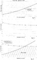
fig. 4 is a graph that shows the variation of the maximum productivity in relation to the number of sides of a cast product and estimated in relation to phenomena of bulging; -
fig. 5 is a graph that shows the variation of the maximum productivity in relation to the number of sides of a cast product and estimated so as to guarantee a thickness of the solid skin of the cast product at exit from the crystallizer; -
fig. 6 is a graph that combines the graphs offigs. 4 and 5 and identifies the work field for the choice of the productivity of said casting apparatus. - To facilitate comprehension, the same reference numbers have been used, where possible, to identify identical common elements in the drawings. It is understood that elements and characteristics of one embodiment can conveniently be incorporated into other embodiments without further clarifications.
- Embodiments of the present invention concern a method for the continuous casting of a product P along a
curved casting line 18. - By
curved casting line 18 we intend to comprise both an apparatus that develops along a completely curved casting line, and also a vertical casting line in the initial segment and subsequently curved. - With reference to
fig. 3 , an apparatus for continuous casting, according to the present invention, is indicated in its entirety by thereference number 10 and is suitable to cast a metal product P selected in a group comprising billets and blooms. - The
apparatus 10 comprises acrystallizer 11 having a tubular shape and provided with atubular cavity 12 in which liquid metal M is discharged during use. - The
crystallizer 11 allows to solidify the liquid metal M, generating a solidifiedexternal skin 13. - The
skin 13 has a thickness "t" which progressively increases from the solidification zone, inside thecrystallizer 11, until reaching a point, called "kissing point K", usually outside thecrystallizer 11, in which the product P is completely solidified. - According to possible embodiments, the
tubular cavity 12 has a polygonal cross section shape determined by a determinate number of sides "n". By way of example only, the cross section of thetubular cavity 12 has a square, hexagonal, octagonal, or decagonal shape. - However, it is not excluded that the cross section can have a different number of sides, for example triangular, pentagonal or heptagonal.
- Embodiments of the present invention can provide that the
tubular cavity 12 is defined by a plurality ofwalls 14 defining the sides of thecrystallizer 11. - In some embodiments of the present invention, the
walls 14 of thecrystallizer 11 all have the same sizes. In this way theskin 13 that is formed during casting has a conformation substantially mating with that of thecasting cavity 12, and the sides of theskin 13, having the same sizes, will be subjected to the same stresses, for example to the same ferrostatic pressure. - However, it is not excluded that in possible variant embodiments the
walls 14 have different sizes or width. - The
crystallizer 11 is provided with afirst end 15 through which the liquid metal M is fed, and asecond end 16, opposite thefirst end 15, through which the partly solidified product P is discharged from thecrystallizer 11. - The
crystallizer 11 is provided with cooling means 17 configured to cool thecrystallizer 11 which, in turn, exerts a cooling action on the liquid metal M and allows the formation of theskin 13. - Downstream of the
crystallizer 11 there are support and curvingrollers 19 configured to support and curve the product P along thecasting line 18. - In particular, it is provided that the support and curving
rollers 19 are installed reciprocally distanced along the casting line and are located in succession one on the intrados side and the other on the extrados side of thecasting line 18 itself. - The support and curving
rollers 19 can be disposed only on the extrados and intrados side of thecasting line 18. - In accordance with possible solutions, it can be provided that the support and curving
rollers 19 are installed directly downstream of the exit from thecrystallizer 11. - According to the present invention, the product P exiting from the
crystallizer 11 is therefore directly accompanied and curved along the casting line by the support and curvingrollers 19 and without the aid of lateral containing sectors of the cross section of the product P. - By lateral containing sectors of the cross section, we mean containing elements which are located facing each other to peripherally surround the sides of the cross section of the cast product P.
- In accordance with other solutions, downstream of the support and curving
rollers 19, thecasting apparatus 10 comprises straightening and/or drawingunits 20 configured to straighten the product P and/or possibly carry out an action to compress it. - The straightening and/or
drawing unit 20 determines a casting speed Vc of the product itself along thecasting line 18. - For this purpose, the straightening and/or
drawing unit 20 can be provided withrollers 22 having the function of straightening, compression, and/or drawing. - According to a possible embodiment of the present invention, the product P exiting from the
crystallizer 11 is supported and guided, or curved, only by the action of the support and curvingrollers 19, until it enters the straightening and/ordrawing unit 20. - According to possible solutions, the support and curving
rollers 19 can be provided with cooling devices, such as internal cooling channels, to cool both the support and curvingrollers 19 themselves, and theskin 13 of the product P. - In accordance with other embodiments of the present invention, the
apparatus 10 can also comprise cooling means 21, for example nozzles, to deliver nebulized water, so as to further cool the product P. - The method according to the present invention provides to cast the liquid metal M into the
crystallizer 11. - The product P exiting from the
crystallizer 11 is curved along the casting line by means of the support and curvingrollers 19 and without the aid of lateral containing sectors of the cross section of the product P. - According to one aspect of the present invention, before starting the casting, the method comprises setting a productivity Pr of the
casting line 18 which is selected inside a predefined work field and a function of the number of sides n of thetubular cavity 12, or of thecrystallizer 11. - Furthermore, the method provides to supply the
crystallizer 11 having a number of sides n determined so as to obtain, or achieve, said preset productivity Pr and so that the product P, at exit from thecrystallizer 11, has at least a minimum thickness tmin of solidifiedskin 13 and so that the deformation of theskin 13 is limited below a threshold value. - The choice of the
crystallizer 11, according to the present invention, allows to prevent the occurrence of deformations of theskin 13 such as to cause any damage thereto. In particular, the deformations of theskin 13 must be such as not to exceed at least the breaking or yield point of theskin 13 itself. - During casting, the
skin 13 of the product P is in fact subjected to a phenomenon of deformation, or bulging. - The phenomenon of bulging is caused by the ferrostatic pressure which the liquid metal M exerts on the
skin 13 of the product P and which causes a maximum deformation or deflection of theskin 13. - Furthermore, during casting, it is necessary to guarantee that the product P exiting from the
crystallizer 11 has a minimum thickness of itsskin 13 such as to support said phenomena of bulging. - In accordance with possible embodiments, and as described also hereafter, the work field is delimited by a first achievable maximum productivity Prmaxb determined in such a way as to prevent the
skin 13 from deforming above said threshold, or from being subject to the phenomenon of bulging, and a second maximum productivity achievable Prmaxt determined so that theskin 13 has at least the minimum thickness tmin. - In order to prevent the occurrence of the problem of bulging, Applicant has experimentally identified a correlation between the sizes of the side of the product P and the maximum casting speed that can be expressed by the relation:

- W is the size of the side [m];
- Vcmaxb is the maximum casting speed [m/min] above which a phenomenon of bulging occurs, at a level unsustainable by the wall of the product P;
- K is a constant comprised between 0.04 and 0.05 (m3/s)0.5, preferably between 0.042 and 0.047 (m3/s)0.5.
- The casting speed at regime Vc respects the following inequality:

- Thanks to this formula it is possible to determine the optimal size of the side of each product for determinate maximums of achievable casting speed, avoiding the use of containment and at the same time avoiding the risk of unsustainable bulging.
- At this point, knowing the maximum casting speed at which to produce and the optimal sizes of the sides in order to contain bulging, it is possible to calculate the production limits for products of different polygonal shapes.
- From literature, the productivity of a casting line is defined as the mass flow rate passing through the crystallizer, which can be calculated as:

- Pr is hourly productivity [t/h]
- ρ is the density of the solid metal, for example solid steel, which includes the solidification effect [kg/m3]
- A is the product section P [m2]
- Vc is the casting speed [m / min]
- Similarly, using the maximum casting speed Vcmaxb instead of the casting speed Vc, the achievable maximum productivity Prmaxb is determined with profiles of every polygonal shape, beyond which unsustainable problems of bulging arise.

- In turn, the section of the product P can be calculated as:

- W is the size of the side [m]
- f is the fixed area number.
- The fixed area number represents the ratio between the area of the polygon and the area of a square which has for its side the side of the polygon.
- Each regular polygon has its own fixed area number, summarized below:
Regular polygon f Triangle 0.433 Square 1 Pentagon 1.720 Hexagon 2.598 Heptagon 3.634 Octagon 4.828 Nonagon 6.182 Decagon 7.694 - The fixed area number can however be calculated trigonometrically as:

n is the number of sides of the polygon. - At this point it is possible to replace, in the formula of the maximum hourly productivity Prmaxb seen previously, the terms of the maximum casting speed Vcmaxb and of the area A of the product P, again according to the previous formulas and taking into account the previously selected factor K

- Thanks to the latter formula it is therefore possible to establish, for every possible profile of the product P, which maximum productivity can be achieved without having to resort to the containing sectors downstream of the crystallizer.
- In order to avoid problems with deformation of the
skin 13, the productivity Pr of thecasting line 18 must be less than or, at most, equal to the Prmaxb defined above, that is, Pr ≤ Prmaxb must be obtained. -
Fig. 4 shows the maximum productivity Prmaxb associated with products P having from a minimum of 4 sides to a maximum of 10, using the following data by way of example:Description Symbol Value Unit Density of product P ρ 7750 kg/m3 Maximum constant bulging K 0.044 (m3/s)0.5 - Applying the above formula we obtain the following productivities Prmaxb:
Number of sides of product P Maximum bulging limit 4 54.0 5 92.9 6 140.3 7 196.3 8 260.8 9 333.9 10 415.6 - From the analysis of
fig. 4 it is possible to notice that the area subtended by the curve of maximum productivity represents every possible production capacity, for each type of product P, which does not require containing downstream of the crystallizer. - For example, a productivity Pr of 140 t/h can be achieved, regardless of the size of the side W, with a
crystallizer 11 of hexagonal shape at full power, or with an octagonal shape at medium power. - In advantageous embodiments, the shape of the polygon of the
casting cavity 12 is selected from square, hexagon and octagon, that is, a polygon having a number of sides equal to four, or six, or eight. - There is also another physical limit to productivity regarding the minimum thickness tmin of the
skin 13 exiting from thecrystallizer 11 in order to guarantee that the product P is self-supporting. - The
skin 13, in fact, since it is not supported by the containing sectors, must have a thickness sufficient to allow the product P to exit integral from thecrystallizer 11, to proceed along thecasting line 18 and to cool, without ever yielding to unsustainable phenomena of bulging or breaking. - The thickness t of the
skin 13 of the product P exiting from thecrystallizer 11 is directly linked to the casting speed Vc; in fact, through the solidification constant KS of the product P, a higher casting speed Vc determines a lesser thickness of theskin 13 of the product P and vice versa. - The thickness t of the
skin 13 of the product P exiting from thecrystallizer 11 must therefore be greater than or equal to a minimum safety thickness tmin. - In the state of the art, the minimum safety thickness tmin can generally be between 6mm and 10mm, and the present invention suggests preferably between 7mm and 9mm, even more preferably about 8mm.
- The limit to productivity Pr due to the minimum thickness tmin at exit from the
crystallizer 11 is obtained starting from the equation known from literature for a thickness equal to tmin:
- As can be seen, the limit in terms of minimum thickness tmin entails the need not to exceed a determinate value of casting speed Vcmaxt.
- This limitation to the casting speed Vcmaxt consequently implies a constraint on the maximum productivity Prmaxt achievable:

- The side of the polygon W can be expressed as a function of the diameter D of the circumference inscribed in the polygon which describes the section of the product P, since for the purposes of cooling the edges are less problematic, as they cool more quickly.
- In particular it is known that:


- Unlike what is obtained with regard to bulging, the maximum productivity with the limit in terms of minimum thickness, besides being a function of the number of sides n, also depends on tmin and D.
- The productivity Pr of the casting line, estimated taking into consideration a limit thickness of the skin, must therefore be less than or equal to the Prmaxt calculated above, or Pr≤Prmaxt.
-
Fig. 5 represents the maximum productivity Prmaxt associated with products P having from a minimum of 4 sides to a maximum of 10, using the following data by way of example:Description Symbol Value Unit Density of product P ρ 7750 kg/m3 Solidification constant KS 3.87E-03 m/s0.5 Inscribed diameter D 0.22 m Minimum thickness tmin 0.008 m - Using these data in the above formula, we obtain the following productivity limits Prmaxt for different types of products P:
Number of sides of product P Minimum thickness limit 4 316.49 5 287.43 6 274.09 7 266.72 8 262.19 9 259.18 10 257.09 - In particular, the curve which describes the maximum productivity Prmaxt has an asymptotic development, being essentially a function of the expression n*tan(π/n) which for n tending to infinity assumes the constant value π. This development means that, beyond a certain n, the maximum productivity Prmaxt achievable remains constant, so that a further increase in the number of sides n does not lead to any advantage.
- According to one aspect of the present invention, the
casting line 18 can have a productivity Pr greater than or equal to 60 t/h. - From the graph in
fig. 5 it is thus clear that the achievable maximum productivity for a cast product P having D equal to 220 mm and tmin of 8 mm is about 260 t/h, with n equal to eight (octagon), while with a square crystallizer, because of maximum bulging, it is not possible to exceed 54 t/h. In addition, beyond a number of sides equal to ten, the maximum productivity settles at a value of 257 t/h. Therefore, in order to achieve a maximum productivity close to 260 t/h, it is best to adopt a crystallizer with 8 sides, since the use of a crystallizer with 9 sides would entail problems in moving and supporting the product P, while using a crystallizer with 10 or more sides would not have any advantage in terms of productivity. - From the union of the curves shown in
figs. 4 and 5 which show the limited productivities, respectively one based on the maximum tolerable bulging (Prmaxb), and the other with respect to the minimum skin thickness necessary to support the product P at exit from the crystallizer (Prmaxt), the graph shown infig. 6 is obtained, which shows the optimal work field, in which the designer can choose the type of product P and the desired productivity, represented by the area subtended by the two curves. - From the analysis of the graph in
fig. 6 it is therefore seen that for profiles from square to octagonal, productivity is limited mainly by the containing of the bulging, whereas from octagonal onward the limit is set by the minimum thickness of skin which must be guaranteed to the product exiting from the crystallizer. - The designer who wants to obtain very high productivity without the aid of containment will have to opt for casting at least octagonal sections, while for more modest productivity he will be able to choose from a greater range of castable sections.
- In particular, the method provides that the productivity Pr set in the casting line, for the specific number of sides n of the
crystallizer 11 selected, is lower than or equal to the minimum value between the first maximum productivity (Prmaxb) and the second maximum productivity (Prmaxt). - Furthermore, by combining the productivities expressed above Prmaxb and Prmaxt it is possible to identify an optimal number of sides which allows to optimize the casting productivity.
- In particular, if Prmaxb = Prmaxt we obtain


- From this expression of the optimal number of sides it is also possible, based on the expressions above, to identify the limits of the casting speed Vc of the
casting line 18. - In particular, if the
crystallizer 11 has a number of sides n lower than the optimum number of sides nott, it is provided to cast the product P with a casting speed expressed by the relation:
- While if the
crystallizer 11 has a number of sides n greater than the number of optimum sides nott, it is provided to cast the product P with a casting speed Vc expressed by the relation:
- In the following claims, the sole purpose of the references in brackets is to facilitate reading: they must not be considered as restrictive factors with regard to the field of protection claimed in the specific claims.
Claims (8)
- Method for the continuous casting of a product (P), chosen from billets or blooms, along a curved casting line (18), said method providing to cast a liquid metal (M) in a crystallizer (11) that is provided with a tubular cavity (12) having a polygonal cross section defined by a determinate number of sides (n), characterized in that said product (P) exiting from said crystallizer (11) is curved along said casting line (18) by support and curving rollers (19) and without the aid of lateral containing sectors of the cross section of said product (P), in that said method comprises setting a productivity (Pr) of said casting line (18) chosen inside a work field delimited by a first achievable maximum productivity (Prmaxb), and by a second achievable maximum productivity (Prmaxt), said first achievable maximum productivity (Prmaxb) being defined by the expression:
 ρ: is the density of the solid metal,K: is a constant comprised between 0.04 and 0.05; andn: is the number of sides of said polygon of the tubular cavity (12);and said second achievable maximum productivity (Prmaxt) being defined by the expression:wherein
 ρ: is the density of the solid metal;D: is a size of the cross section of said product (P);Ks: is a solidification constant determined as a function of the material of said liquid metal (M);tmin: is a preset minimum thickness of said product (P);n: is the number of sides of said polygon of the tubular cavity (12);in that said productivity (Pr) is set so that it is less than or equal to the minimum value between said first maximum productivity (Prmaxb) and said second maximum productivity (Prmaxt), and in that said method comprises supplying said crystallizer (11) having a number of sides (n) determined so as to obtain said set productivity (Pr).
 - Method as in claim 1, characterized in that it provides to determine an optimal number of sides (nott) suitable to optimize said productivity (Pr), said optimal number of sides (nott) being determined by the expression:
 int: represents the integer number approximated by defect of the expression comprised between the brackets;K: is a constant comprised between 0.04 and 0.05;Ks: is a solidification constant determined as a function of the material of said liquid metal (M);D: is a size of the cross section of said product (P);tmin is a preset minimum thickness of said product (P).
 - Method as in claim 2, characterized in that if said crystallizer (11) has a number of sides (n) fewer than said number of optimal sides (nott), the method provides to cast said product (P) at a casting speed expressed by the relation:

- Method as in claim 2, characterized in that if said crystallizer (11) has a number of sides (n) bigger than said number of optimal sides (nott), the method provides to cast said product (P) at a casting speed expressed by the relation:

- Method as in any claim hereinbefore, characterized in that said number of sides (n) is chosen from between 4, 6 and 8.
- Method as in any claim hereinbefore, characterized in that said casting line (18) has a productivity (Pr) greater than or equal to 60 t/h.
- Method as in any claim hereinbefore, characterized in that said tubular cavity (12) is defined by a plurality of walls (14) defining the sides of the crystallizer (11), and in that the walls (14) of the crystallizer (11) are all the same size.
- Method as in any claim hereinbefore, characterized in that said safety minimum thickness tmin is comprised between 7mm and 9mm, even more preferably about 8mm.
Priority Applications (2)
| Application Number | Priority Date | Filing Date | Title |
|---|---|---|---|
| EP19206073.9A EP3628415A1 (en) | 2017-06-16 | 2018-06-15 | Continuous casting method and corresponding apparatus |
| PL18739653T PL3493929T3 (en) | 2017-06-16 | 2018-06-15 | Continuous casting method |
Applications Claiming Priority (2)
| Application Number | Priority Date | Filing Date | Title |
|---|---|---|---|
| IT102017000067508A IT201700067508A1 (en) | 2017-06-16 | 2017-06-16 | CONTINUOUS CASTING METHOD AND ITS APPARATUS |
| PCT/IT2018/050107 WO2018229808A1 (en) | 2017-06-16 | 2018-06-15 | Continuous casting method and corresponding apparatus |
Related Child Applications (2)
| Application Number | Title | Priority Date | Filing Date |
|---|---|---|---|
| EP19206073.9A Division-Into EP3628415A1 (en) | 2017-06-16 | 2018-06-15 | Continuous casting method and corresponding apparatus |
| EP19206073.9A Division EP3628415A1 (en) | 2017-06-16 | 2018-06-15 | Continuous casting method and corresponding apparatus |
Publications (2)
| Publication Number | Publication Date |
|---|---|
| EP3493929A1 EP3493929A1 (en) | 2019-06-12 |
| EP3493929B1 true EP3493929B1 (en) | 2019-12-11 |
Family
ID=60138855
Family Applications (2)
| Application Number | Title | Priority Date | Filing Date |
|---|---|---|---|
| EP19206073.9A Pending EP3628415A1 (en) | 2017-06-16 | 2018-06-15 | Continuous casting method and corresponding apparatus |
| EP18739653.6A Active EP3493929B1 (en) | 2017-06-16 | 2018-06-15 | Continuous casting method |
Family Applications Before (1)
| Application Number | Title | Priority Date | Filing Date |
|---|---|---|---|
| EP19206073.9A Pending EP3628415A1 (en) | 2017-06-16 | 2018-06-15 | Continuous casting method and corresponding apparatus |
Country Status (8)
| Country | Link |
|---|---|
| US (2) | US10758972B2 (en) |
| EP (2) | EP3628415A1 (en) |
| CN (2) | CN110035842B (en) |
| EA (1) | EA034010B1 (en) |
| HU (1) | HUE048641T2 (en) |
| IT (1) | IT201700067508A1 (en) |
| PL (1) | PL3493929T3 (en) |
| WO (1) | WO2018229808A1 (en) |
Families Citing this family (1)
| Publication number | Priority date | Publication date | Assignee | Title |
|---|---|---|---|---|
| IT201900010347A1 (en) * | 2019-06-28 | 2020-12-28 | Danieli Off Mecc | CRYSTALLIZER FOR CONTINUOUS CASTING OF A METALLIC PRODUCT AND RELATIVE CASTING PROCEDURE |
Family Cites Families (21)
| Publication number | Priority date | Publication date | Assignee | Title |
|---|---|---|---|---|
| AT285077B (en) * | 1965-01-20 | 1970-10-12 | Benteler Geb Paderwerk | Continuous casting process for the two-stage production of semi-finished steel profiles |
| US3924673A (en) * | 1968-03-18 | 1975-12-09 | Gamma Engineering Ltd | Apparatus for producing continuous metal castings |
| DE2405598B2 (en) * | 1974-02-06 | 1975-11-27 | Gebr. Boehler & Co Ag, Wien, Niederlassung Gebr. Boehler & Co Ag Wien, Verkaufsniederlassung Buederich, 4005 Buederich | Segment mold |
| AT344346B (en) * | 1975-04-30 | 1978-07-10 | Voest Ag | DEVICE FOR LEADING A CAST RAND |
| US4273180A (en) * | 1979-03-08 | 1981-06-16 | Tertishnikov Anatoly S | Process and apparatus for continuous casting of metal in electromagnetic field |
| LU81982A1 (en) * | 1979-12-11 | 1981-07-23 | Arbed | CONTINUOUS CASTING MILLS SUITABLE FOR CURVING STEEL MULTIPLE STEEL PROFILES AND METHOD FOR THE FINISHING OF THEIR INTERIOR SURFACES |
| CA1204574A (en) * | 1981-08-18 | 1986-05-20 | Hanji Oba | Apparatus for continuous casting of steel |
| JP2989737B2 (en) * | 1993-11-25 | 1999-12-13 | 勝彦 山田 | Continuous casting and continuous casting / rolling of steel |
| IT1267298B1 (en) * | 1994-09-30 | 1997-01-28 | Danieli Off Mecc | CONTINUOUS CASTING DEVICE FOR ROUND SECTION AND FLAT SECTION PRODUCTS |
| DE19639299C2 (en) * | 1996-09-25 | 2001-02-22 | Sms Demag Ag | Device for producing a polygonal or profile format in a continuous caster |
| EP0917922B1 (en) * | 1997-11-21 | 2003-06-25 | SMS Demag AG | Process and plant for continuous casting slabs |
| JP4164163B2 (en) * | 1998-07-31 | 2008-10-08 | 株式会社神戸製鋼所 | Metal casting mold |
| WO2002011923A1 (en) * | 2000-08-10 | 2002-02-14 | Sms Demag Aktiengesellschaft | Method and strand guide for supporting, guiding and cooling casting strands made of steel, especially preliminary sections for girders |
| DE10133093A1 (en) * | 2000-08-10 | 2002-02-21 | Sms Demag Ag | Process and strand guide for supporting, guiding and cooling cast strands made of steel, in particular of pre-profiles for beams |
| TWI288676B (en) * | 2002-07-06 | 2007-10-21 | Sms Demag Ag | Method and casting roller plant for the semi-endless or endless rolling by casting of a metal in particular a steel strip which may be transversely cut as required after solidification |
| DE102006005635A1 (en) * | 2006-02-08 | 2007-08-09 | Sms Demag Ag | Roller hearth furnace for heating and / or temperature compensation of continuous casting products made of steel or steel alloy and its arrangement in front of a hot strip finishing train |
| CN101920316B (en) * | 2010-08-03 | 2015-08-19 | 中国重型机械研究院有限公司 | A kind of method for reforming continuous casting machine solving liquid level fluctuation of crystallizer |
| EP2441540A1 (en) | 2010-10-12 | 2012-04-18 | Siemens VAI Metals Technologies GmbH | Method and assembly for energy-efficient production of hot rolled steel strips |
| CN102303104A (en) * | 2011-09-30 | 2012-01-04 | 中冶南方工程技术有限公司 | Method for controlling narrow side bulging in continuous casting of ultra-thick plate blanks |
| US10155263B2 (en) * | 2012-09-28 | 2018-12-18 | Ati Properties Llc | Continuous casting of materials using pressure differential |
| CN103386472B (en) * | 2013-08-05 | 2016-03-02 | 中冶南方工程技术有限公司 | A kind of acquisition methods of continuous cast mold outlet base shell safe thickness and device |
-
2017
- 2017-06-16 IT IT102017000067508A patent/IT201700067508A1/en unknown
-
2018
- 2018-06-15 EA EA201990507A patent/EA034010B1/en not_active IP Right Cessation
- 2018-06-15 US US16/333,781 patent/US10758972B2/en active Active
- 2018-06-15 CN CN201880003573.6A patent/CN110035842B/en active Active
- 2018-06-15 CN CN202010268659.0A patent/CN111266540B/en active Active
- 2018-06-15 WO PCT/IT2018/050107 patent/WO2018229808A1/en unknown
- 2018-06-15 EP EP19206073.9A patent/EP3628415A1/en active Pending
- 2018-06-15 EP EP18739653.6A patent/EP3493929B1/en active Active
- 2018-06-15 HU HUE18739653A patent/HUE048641T2/en unknown
- 2018-06-15 PL PL18739653T patent/PL3493929T3/en unknown
-
2020
- 2020-08-20 US US16/998,547 patent/US11130172B2/en active Active
Non-Patent Citations (11)
| Title |
|---|
| ALAN W. CRAMB: "The Making, Shaping and Treating of Steel", 2003, THE AISE STEEL FOUNDATION, ISBN: 0-930767-04-7, article "Chapter 15 The Design of Flat and Long Products Casters. 18.2.1 Requirements", XP055770729 |
| ANONYMOUS: "Inkreis", ENZYKLOPÄDIE WIKIPEDIA, 30 July 2020 (2020-07-30), XP055770690, Retrieved from the Internet <URL:https://de.wikipedia.org/wiki/Inkreis> |
| C. LI ET AL.: "MAXIMUM CASTING SPEED FOR CONTINUOUS CAST STEEL BILLETS BASED ON SUB-MOLD BULGING COMPUTATION", 85TH STEELMAKING CONF. PROC., ISS, 10 March 2002 (2002-03-10) - 12 March 2002 (2002-03-12), Warrendale, PA, pages 109 - 130, XP055770596 |
| J.K. PARK ET AL.: "Analysis of thermomechanical behavior in billet casting with different mould corner radii", IRON AND STEELMAKING, vol. 29, no. 5, October 2002 (2002-10-01), pages 359 - 375, XP055770599 |
| J.K. PARK ET AL.: "ANALYSIS OF THERMO-MECHANICAL BEHAVIOR IN BILLET CASTING", 60 TH ELECTRIC FURNACE CONFERENCE ELECTRIC FURNACE CONFERENCE PROCEEDINGS, 10 November 2002 (2002-11-10) - 12 November 2002 (2002-11-12), San Antonio, TX, pages 669 - 685, XP055770603 |
| K. KELLER ET AL.: "The House of the World's Longest Billet - The New Micromill Danieli (MI.DA) at CMC Steel Arizona An Innovative Process for the Most Competitive Production of Rebar Product", AISTECH 2010 PROCEEDINGS, 2010, pages 727 - 734, XP055770679 |
| KLAUS SCHWERDTFEGER: "Metallurgie des Stranggießens", 1992, STAHL EISEN, Düsseldorf, article "Bild 1.3.15, 1.3.16 und 1.3.17", pages: 20 - 23, XP055770701 |
| L. KLIMES ET AL.: "IMPACT OF CASTING SPEED ON THE TEMPERATURE FIELD OF CONTINUOUSLY CAST STEEL BILLETS", MATERIALS AND TECHNOLOGY, vol. 47, no. 4, 2013, pages 507 - 513, XP055770674 |
| L. POCHMARSKI ET AL.: "Revamping of the Donawitz Bloom Caster to Improve Quality and to Increase Productivity", CONFERENCE CCC'96, May 1996 (1996-05-01), Linz, Austria, pages 1 - 10, XP055770683 |
| S. KITTAKA ET AL.: "High speed casting mold for billet caster (NS Hyper Mold)", NIPPON STEEL TECHNICAL REPORT NO. 82, July 2000 (2000-07-01), pages 65 - 70, XP055770593 |
| W. BRANDL ET AL.: "Donawitz Compact - The Process Route of Europe 's No. 1 Rail Producer", CONFERENCE CCC 2000, June 2000 (2000-06-01), Linz, Austria, pages 1 - 6, XP055770686 |
Also Published As
| Publication number | Publication date |
|---|---|
| CN111266540A (en) | 2020-06-12 |
| WO2018229808A1 (en) | 2018-12-20 |
| HUE048641T2 (en) | 2020-08-28 |
| US20200094316A1 (en) | 2020-03-26 |
| EP3628415A1 (en) | 2020-04-01 |
| CN110035842B (en) | 2020-04-28 |
| IT201700067508A1 (en) | 2018-12-16 |
| US10758972B2 (en) | 2020-09-01 |
| CN110035842A (en) | 2019-07-19 |
| EP3493929A1 (en) | 2019-06-12 |
| US20210031260A1 (en) | 2021-02-04 |
| PL3493929T3 (en) | 2020-05-18 |
| EA034010B1 (en) | 2019-12-18 |
| CN111266540B (en) | 2021-09-28 |
| EA201990507A1 (en) | 2019-07-31 |
| US11130172B2 (en) | 2021-09-28 |
Similar Documents
| Publication | Publication Date | Title |
|---|---|---|
| EP3144080B1 (en) | Continuous casting method for slab | |
| EP2818259B1 (en) | Pre-control method of head and tail shapes of continuous casting slab for reducing the removed amount from the head and tail of hot-rolled intermediate slab | |
| US4926930A (en) | Process and machine for the continuous casting of a thin metal product | |
| US20020017375A1 (en) | Method and apparatus for high-speed continuous casting plants with a strand thickness reduction during solidification | |
| US11130172B2 (en) | Continuous casting method and corresponding apparatus | |
| US5871040A (en) | Process for continuously casting thin slabs | |
| US3638713A (en) | Continuous casting method including strand support adjustment | |
| US20120132390A1 (en) | Device and method for horizontal casting of a metal band | |
| US3209452A (en) | Method of producing bars or sections by continuous casting | |
| EP1940566B1 (en) | Metal strip production process and plant | |
| US3650314A (en) | Apparatus for manufacturing stretch-formed products of high-melting metals | |
| DE2023407A1 (en) | Continuous casting plant for slabs | |
| JP2019141874A (en) | Cold rolling method of metal strip | |
| CN103878174A (en) | Rolling method for expanding capacity of coiling machine and eliminating impressions of heads of coiled materials | |
| US3900066A (en) | Apparatus for continuous casting a metal strand shaped to provide concave surfaces | |
| RU2800555C1 (en) | Mould for continuous casting of a metal product and corresponding casting method | |
| CN114364471B (en) | Crystallizer for continuous casting of metal products and corresponding casting method | |
| US4022369A (en) | Curved roller track for continuously cast ingots | |
| RU2785053C1 (en) | Method for production of installation for continuous casting and installation for continuous casting, obtained by this method | |
| JPS6023882B2 (en) | Rolling method for long steel | |
| KR20200034462A (en) | Continuous casting apparatus and method | |
| JPH0346218B2 (en) | ||
| US4023610A (en) | Strand support method | |
| JPS6349561B2 (en) | ||
| JP2006051513A (en) | Apparatus for cooling h-section steel |
Legal Events
| Date | Code | Title | Description |
|---|---|---|---|
| STAA | Information on the status of an ep patent application or granted ep patent |
Free format text: STATUS: UNKNOWN |
|
| STAA | Information on the status of an ep patent application or granted ep patent |
Free format text: STATUS: THE INTERNATIONAL PUBLICATION HAS BEEN MADE |
|
| PUAI | Public reference made under article 153(3) epc to a published international application that has entered the european phase |
Free format text: ORIGINAL CODE: 0009012 |
|
| STAA | Information on the status of an ep patent application or granted ep patent |
Free format text: STATUS: REQUEST FOR EXAMINATION WAS MADE |
|
| 17P | Request for examination filed |
Effective date: 20190307 |
|
| AK | Designated contracting states |
Kind code of ref document: A1 Designated state(s): AL AT BE BG CH CY CZ DE DK EE ES FI FR GB GR HR HU IE IS IT LI LT LU LV MC MK MT NL NO PL PT RO RS SE SI SK SM TR |
|
| AX | Request for extension of the european patent |
Extension state: BA ME |
|
| GRAP | Despatch of communication of intention to grant a patent |
Free format text: ORIGINAL CODE: EPIDOSNIGR1 |
|
| STAA | Information on the status of an ep patent application or granted ep patent |
Free format text: STATUS: GRANT OF PATENT IS INTENDED |
|
| INTG | Intention to grant announced |
Effective date: 20190723 |
|
| GRAS | Grant fee paid |
Free format text: ORIGINAL CODE: EPIDOSNIGR3 |
|
| GRAA | (expected) grant |
Free format text: ORIGINAL CODE: 0009210 |
|
| STAA | Information on the status of an ep patent application or granted ep patent |
Free format text: STATUS: THE PATENT HAS BEEN GRANTED |
|
| AK | Designated contracting states |
Kind code of ref document: B1 Designated state(s): AL AT BE BG CH CY CZ DE DK EE ES FI FR GB GR HR HU IE IS IT LI LT LU LV MC MK MT NL NO PL PT RO RS SE SI SK SM TR |
|
| DAV | Request for validation of the european patent (deleted) | ||
| DAX | Request for extension of the european patent (deleted) | ||
| REG | Reference to a national code |
Ref country code: GB Ref legal event code: FG4D |
|
| REG | Reference to a national code |
Ref country code: CH Ref legal event code: EP |
|
| REG | Reference to a national code |
Ref country code: AT Ref legal event code: REF Ref document number: 1211688 Country of ref document: AT Kind code of ref document: T Effective date: 20191215 |
|
| REG | Reference to a national code |
Ref country code: DE Ref legal event code: R096 Ref document number: 602018001586 Country of ref document: DE |
|
| REG | Reference to a national code |
Ref country code: IE Ref legal event code: FG4D |
|
| REG | Reference to a national code |
Ref country code: RO Ref legal event code: EPE |
|
| REG | Reference to a national code |
Ref country code: NL Ref legal event code: MP Effective date: 20191211 |
|
| REG | Reference to a national code |
Ref country code: LT Ref legal event code: MG4D |
|
| PG25 | Lapsed in a contracting state [announced via postgrant information from national office to epo] |
Ref country code: FI Free format text: LAPSE BECAUSE OF FAILURE TO SUBMIT A TRANSLATION OF THE DESCRIPTION OR TO PAY THE FEE WITHIN THE PRESCRIBED TIME-LIMIT Effective date: 20191211 Ref country code: BG Free format text: LAPSE BECAUSE OF FAILURE TO SUBMIT A TRANSLATION OF THE DESCRIPTION OR TO PAY THE FEE WITHIN THE PRESCRIBED TIME-LIMIT Effective date: 20200311 Ref country code: GR Free format text: LAPSE BECAUSE OF FAILURE TO SUBMIT A TRANSLATION OF THE DESCRIPTION OR TO PAY THE FEE WITHIN THE PRESCRIBED TIME-LIMIT Effective date: 20200312 Ref country code: NO Free format text: LAPSE BECAUSE OF FAILURE TO SUBMIT A TRANSLATION OF THE DESCRIPTION OR TO PAY THE FEE WITHIN THE PRESCRIBED TIME-LIMIT Effective date: 20200311 Ref country code: SE Free format text: LAPSE BECAUSE OF FAILURE TO SUBMIT A TRANSLATION OF THE DESCRIPTION OR TO PAY THE FEE WITHIN THE PRESCRIBED TIME-LIMIT Effective date: 20191211 Ref country code: LV Free format text: LAPSE BECAUSE OF FAILURE TO SUBMIT A TRANSLATION OF THE DESCRIPTION OR TO PAY THE FEE WITHIN THE PRESCRIBED TIME-LIMIT Effective date: 20191211 Ref country code: LT Free format text: LAPSE BECAUSE OF FAILURE TO SUBMIT A TRANSLATION OF THE DESCRIPTION OR TO PAY THE FEE WITHIN THE PRESCRIBED TIME-LIMIT Effective date: 20191211 |
|
| PG25 | Lapsed in a contracting state [announced via postgrant information from national office to epo] |
Ref country code: RS Free format text: LAPSE BECAUSE OF FAILURE TO SUBMIT A TRANSLATION OF THE DESCRIPTION OR TO PAY THE FEE WITHIN THE PRESCRIBED TIME-LIMIT Effective date: 20191211 Ref country code: HR Free format text: LAPSE BECAUSE OF FAILURE TO SUBMIT A TRANSLATION OF THE DESCRIPTION OR TO PAY THE FEE WITHIN THE PRESCRIBED TIME-LIMIT Effective date: 20191211 |
|
| PG25 | Lapsed in a contracting state [announced via postgrant information from national office to epo] |
Ref country code: AL Free format text: LAPSE BECAUSE OF FAILURE TO SUBMIT A TRANSLATION OF THE DESCRIPTION OR TO PAY THE FEE WITHIN THE PRESCRIBED TIME-LIMIT Effective date: 20191211 |
|
| PG25 | Lapsed in a contracting state [announced via postgrant information from national office to epo] |
Ref country code: EE Free format text: LAPSE BECAUSE OF FAILURE TO SUBMIT A TRANSLATION OF THE DESCRIPTION OR TO PAY THE FEE WITHIN THE PRESCRIBED TIME-LIMIT Effective date: 20191211 Ref country code: PT Free format text: LAPSE BECAUSE OF FAILURE TO SUBMIT A TRANSLATION OF THE DESCRIPTION OR TO PAY THE FEE WITHIN THE PRESCRIBED TIME-LIMIT Effective date: 20200506 Ref country code: ES Free format text: LAPSE BECAUSE OF FAILURE TO SUBMIT A TRANSLATION OF THE DESCRIPTION OR TO PAY THE FEE WITHIN THE PRESCRIBED TIME-LIMIT Effective date: 20191211 Ref country code: CZ Free format text: LAPSE BECAUSE OF FAILURE TO SUBMIT A TRANSLATION OF THE DESCRIPTION OR TO PAY THE FEE WITHIN THE PRESCRIBED TIME-LIMIT Effective date: 20191211 Ref country code: NL Free format text: LAPSE BECAUSE OF FAILURE TO SUBMIT A TRANSLATION OF THE DESCRIPTION OR TO PAY THE FEE WITHIN THE PRESCRIBED TIME-LIMIT Effective date: 20191211 |
|
| REG | Reference to a national code |
Ref country code: HU Ref legal event code: AG4A Ref document number: E048641 Country of ref document: HU |
|
| PG25 | Lapsed in a contracting state [announced via postgrant information from national office to epo] |
Ref country code: IS Free format text: LAPSE BECAUSE OF FAILURE TO SUBMIT A TRANSLATION OF THE DESCRIPTION OR TO PAY THE FEE WITHIN THE PRESCRIBED TIME-LIMIT Effective date: 20200411 Ref country code: SM Free format text: LAPSE BECAUSE OF FAILURE TO SUBMIT A TRANSLATION OF THE DESCRIPTION OR TO PAY THE FEE WITHIN THE PRESCRIBED TIME-LIMIT Effective date: 20191211 Ref country code: SK Free format text: LAPSE BECAUSE OF FAILURE TO SUBMIT A TRANSLATION OF THE DESCRIPTION OR TO PAY THE FEE WITHIN THE PRESCRIBED TIME-LIMIT Effective date: 20191211 |
|
| REG | Reference to a national code |
Ref country code: DE Ref legal event code: R026 Ref document number: 602018001586 Country of ref document: DE |
|
| PLBI | Opposition filed |
Free format text: ORIGINAL CODE: 0009260 |
|
| PLAX | Notice of opposition and request to file observation + time limit sent |
Free format text: ORIGINAL CODE: EPIDOSNOBS2 |
|
| 26 | Opposition filed |
Opponent name: PRIMETALS TECHNOLOGIES AUSTRIA GMBH Effective date: 20200910 |
|
| PG25 | Lapsed in a contracting state [announced via postgrant information from national office to epo] |
Ref country code: DK Free format text: LAPSE BECAUSE OF FAILURE TO SUBMIT A TRANSLATION OF THE DESCRIPTION OR TO PAY THE FEE WITHIN THE PRESCRIBED TIME-LIMIT Effective date: 20191211 |
|
| REG | Reference to a national code |
Ref country code: AT Ref legal event code: UEP Ref document number: 1211688 Country of ref document: AT Kind code of ref document: T Effective date: 20191211 |
|
| PG25 | Lapsed in a contracting state [announced via postgrant information from national office to epo] |
Ref country code: MC Free format text: LAPSE BECAUSE OF FAILURE TO SUBMIT A TRANSLATION OF THE DESCRIPTION OR TO PAY THE FEE WITHIN THE PRESCRIBED TIME-LIMIT Effective date: 20191211 |
|
| PLAF | Information modified related to communication of a notice of opposition and request to file observations + time limit |
Free format text: ORIGINAL CODE: EPIDOSCOBS2 |
|
| PG25 | Lapsed in a contracting state [announced via postgrant information from national office to epo] |
Ref country code: LU Free format text: LAPSE BECAUSE OF NON-PAYMENT OF DUE FEES Effective date: 20200615 |
|
| PLBB | Reply of patent proprietor to notice(s) of opposition received |
Free format text: ORIGINAL CODE: EPIDOSNOBS3 |
|
| REG | Reference to a national code |
Ref country code: BE Ref legal event code: MM Effective date: 20200630 |
|
| PG25 | Lapsed in a contracting state [announced via postgrant information from national office to epo] |
Ref country code: IE Free format text: LAPSE BECAUSE OF NON-PAYMENT OF DUE FEES Effective date: 20200615 Ref country code: FR Free format text: LAPSE BECAUSE OF NON-PAYMENT OF DUE FEES Effective date: 20200630 |
|
| PG25 | Lapsed in a contracting state [announced via postgrant information from national office to epo] |
Ref country code: BE Free format text: LAPSE BECAUSE OF NON-PAYMENT OF DUE FEES Effective date: 20200630 |
|
| PLCK | Communication despatched that opposition was rejected |
Free format text: ORIGINAL CODE: EPIDOSNREJ1 |
|
| REG | Reference to a national code |
Ref country code: DE Ref legal event code: R100 Ref document number: 602018001586 Country of ref document: DE |
|
| PLBN | Opposition rejected |
Free format text: ORIGINAL CODE: 0009273 |
|
| STAA | Information on the status of an ep patent application or granted ep patent |
Free format text: STATUS: OPPOSITION REJECTED |
|
| PG25 | Lapsed in a contracting state [announced via postgrant information from national office to epo] |
Ref country code: MT Free format text: LAPSE BECAUSE OF FAILURE TO SUBMIT A TRANSLATION OF THE DESCRIPTION OR TO PAY THE FEE WITHIN THE PRESCRIBED TIME-LIMIT Effective date: 20191211 Ref country code: CY Free format text: LAPSE BECAUSE OF FAILURE TO SUBMIT A TRANSLATION OF THE DESCRIPTION OR TO PAY THE FEE WITHIN THE PRESCRIBED TIME-LIMIT Effective date: 20191211 |
|
| 27O | Opposition rejected |
Effective date: 20220205 |
|
| PG25 | Lapsed in a contracting state [announced via postgrant information from national office to epo] |
Ref country code: MK Free format text: LAPSE BECAUSE OF FAILURE TO SUBMIT A TRANSLATION OF THE DESCRIPTION OR TO PAY THE FEE WITHIN THE PRESCRIBED TIME-LIMIT Effective date: 20191211 |
|
| P01 | Opt-out of the competence of the unified patent court (upc) registered |
Effective date: 20230516 |
|
| PG25 | Lapsed in a contracting state [announced via postgrant information from national office to epo] |
Ref country code: SI Free format text: LAPSE BECAUSE OF FAILURE TO SUBMIT A TRANSLATION OF THE DESCRIPTION OR TO PAY THE FEE WITHIN THE PRESCRIBED TIME-LIMIT Effective date: 20191211 |
|
| PGFP | Annual fee paid to national office [announced via postgrant information from national office to epo] |
Ref country code: IT Payment date: 20230620 Year of fee payment: 6 Ref country code: CH Payment date: 20230702 Year of fee payment: 6 |
|
| PGFP | Annual fee paid to national office [announced via postgrant information from national office to epo] |
Ref country code: GB Payment date: 20240627 Year of fee payment: 7 |
|
| PGFP | Annual fee paid to national office [announced via postgrant information from national office to epo] |
Ref country code: DE Payment date: 20240627 Year of fee payment: 7 |
|
| PGFP | Annual fee paid to national office [announced via postgrant information from national office to epo] |
Ref country code: AT Payment date: 20240521 Year of fee payment: 7 |
|
| PGFP | Annual fee paid to national office [announced via postgrant information from national office to epo] |
Ref country code: RO Payment date: 20240528 Year of fee payment: 7 |
|
| PGFP | Annual fee paid to national office [announced via postgrant information from national office to epo] |
Ref country code: PL Payment date: 20240521 Year of fee payment: 7 |
|
| PGFP | Annual fee paid to national office [announced via postgrant information from national office to epo] |
Ref country code: TR Payment date: 20240528 Year of fee payment: 7 Ref country code: HU Payment date: 20240528 Year of fee payment: 7 |