EP3493419B1 - Techniques for beamforming in multi-user systems - Google Patents
Techniques for beamforming in multi-user systems Download PDFInfo
- Publication number
- EP3493419B1 EP3493419B1 EP17205202.9A EP17205202A EP3493419B1 EP 3493419 B1 EP3493419 B1 EP 3493419B1 EP 17205202 A EP17205202 A EP 17205202A EP 3493419 B1 EP3493419 B1 EP 3493419B1
- Authority
- EP
- European Patent Office
- Prior art keywords
- precoder
- respect
- training signal
- analog
- precoding
- Prior art date
- Legal status (The legal status is an assumption and is not a legal conclusion. Google has not performed a legal analysis and makes no representation as to the accuracy of the status listed.)
- Active
Links
- 238000000034 method Methods 0.000 title claims description 88
- 238000012549 training Methods 0.000 claims description 114
- 230000005540 biological transmission Effects 0.000 claims description 68
- 238000010606 normalization Methods 0.000 claims description 33
- 238000012545 processing Methods 0.000 claims description 22
- 230000021615 conjugation Effects 0.000 claims description 16
- 238000004891 communication Methods 0.000 claims description 13
- 230000004044 response Effects 0.000 claims description 3
- 238000003491 array Methods 0.000 description 15
- 238000010586 diagram Methods 0.000 description 14
- 239000013598 vector Substances 0.000 description 12
- 238000013461 design Methods 0.000 description 5
- 230000000875 corresponding effect Effects 0.000 description 4
- 239000011159 matrix material Substances 0.000 description 4
- 238000004590 computer program Methods 0.000 description 2
- 238000000354 decomposition reaction Methods 0.000 description 2
- 230000007423 decrease Effects 0.000 description 2
- 230000001934 delay Effects 0.000 description 2
- 230000003595 spectral effect Effects 0.000 description 2
- 230000001413 cellular effect Effects 0.000 description 1
- 230000001268 conjugating effect Effects 0.000 description 1
- 230000002596 correlated effect Effects 0.000 description 1
- 230000001419 dependent effect Effects 0.000 description 1
- 238000005516 engineering process Methods 0.000 description 1
- 238000002372 labelling Methods 0.000 description 1
- 238000010295 mobile communication Methods 0.000 description 1
- 238000012986 modification Methods 0.000 description 1
- 230000004048 modification Effects 0.000 description 1
- 230000003287 optical effect Effects 0.000 description 1
- 230000001052 transient effect Effects 0.000 description 1
Images


Classifications
-
- H—ELECTRICITY
- H04—ELECTRIC COMMUNICATION TECHNIQUE
- H04B—TRANSMISSION
- H04B7/00—Radio transmission systems, i.e. using radiation field
- H04B7/02—Diversity systems; Multi-antenna system, i.e. transmission or reception using multiple antennas
- H04B7/04—Diversity systems; Multi-antenna system, i.e. transmission or reception using multiple antennas using two or more spaced independent antennas
- H04B7/0413—MIMO systems
- H04B7/0452—Multi-user MIMO systems
-
- H—ELECTRICITY
- H04—ELECTRIC COMMUNICATION TECHNIQUE
- H04B—TRANSMISSION
- H04B17/00—Monitoring; Testing
- H04B17/10—Monitoring; Testing of transmitters
- H04B17/101—Monitoring; Testing of transmitters for measurement of specific parameters of the transmitter or components thereof
- H04B17/104—Monitoring; Testing of transmitters for measurement of specific parameters of the transmitter or components thereof of other parameters, e.g. DC offset, delay or propagation times
-
- H—ELECTRICITY
- H04—ELECTRIC COMMUNICATION TECHNIQUE
- H04B—TRANSMISSION
- H04B17/00—Monitoring; Testing
- H04B17/30—Monitoring; Testing of propagation channels
- H04B17/309—Measuring or estimating channel quality parameters
-
- H—ELECTRICITY
- H04—ELECTRIC COMMUNICATION TECHNIQUE
- H04B—TRANSMISSION
- H04B7/00—Radio transmission systems, i.e. using radiation field
- H04B7/02—Diversity systems; Multi-antenna system, i.e. transmission or reception using multiple antennas
- H04B7/04—Diversity systems; Multi-antenna system, i.e. transmission or reception using multiple antennas using two or more spaced independent antennas
- H04B7/0413—MIMO systems
- H04B7/0456—Selection of precoding matrices or codebooks, e.g. using matrices antenna weighting
- H04B7/046—Selection of precoding matrices or codebooks, e.g. using matrices antenna weighting taking physical layer constraints into account
-
- H—ELECTRICITY
- H04—ELECTRIC COMMUNICATION TECHNIQUE
- H04B—TRANSMISSION
- H04B7/00—Radio transmission systems, i.e. using radiation field
- H04B7/02—Diversity systems; Multi-antenna system, i.e. transmission or reception using multiple antennas
- H04B7/04—Diversity systems; Multi-antenna system, i.e. transmission or reception using multiple antennas using two or more spaced independent antennas
- H04B7/06—Diversity systems; Multi-antenna system, i.e. transmission or reception using multiple antennas using two or more spaced independent antennas at the transmitting station
- H04B7/0613—Diversity systems; Multi-antenna system, i.e. transmission or reception using multiple antennas using two or more spaced independent antennas at the transmitting station using simultaneous transmission
- H04B7/0615—Diversity systems; Multi-antenna system, i.e. transmission or reception using multiple antennas using two or more spaced independent antennas at the transmitting station using simultaneous transmission of weighted versions of same signal
- H04B7/0617—Diversity systems; Multi-antenna system, i.e. transmission or reception using multiple antennas using two or more spaced independent antennas at the transmitting station using simultaneous transmission of weighted versions of same signal for beam forming
-
- H—ELECTRICITY
- H04—ELECTRIC COMMUNICATION TECHNIQUE
- H04B—TRANSMISSION
- H04B7/00—Radio transmission systems, i.e. using radiation field
- H04B7/02—Diversity systems; Multi-antenna system, i.e. transmission or reception using multiple antennas
- H04B7/04—Diversity systems; Multi-antenna system, i.e. transmission or reception using multiple antennas using two or more spaced independent antennas
- H04B7/06—Diversity systems; Multi-antenna system, i.e. transmission or reception using multiple antennas using two or more spaced independent antennas at the transmitting station
- H04B7/0686—Hybrid systems, i.e. switching and simultaneous transmission
-
- H—ELECTRICITY
- H04—ELECTRIC COMMUNICATION TECHNIQUE
- H04B—TRANSMISSION
- H04B7/00—Radio transmission systems, i.e. using radiation field
- H04B7/02—Diversity systems; Multi-antenna system, i.e. transmission or reception using multiple antennas
- H04B7/04—Diversity systems; Multi-antenna system, i.e. transmission or reception using multiple antennas using two or more spaced independent antennas
- H04B7/08—Diversity systems; Multi-antenna system, i.e. transmission or reception using multiple antennas using two or more spaced independent antennas at the receiving station
- H04B7/0868—Hybrid systems, i.e. switching and combining
Definitions
- the disclosure relates to techniques for beamforming in multi-user systems.
- the disclosure particularly relates to a base station for serving multiple user terminals, a corresponding user terminal and a multi-user precoding method.
- the disclosure further relates to a ping-pong beam training method for multi-user MIMO systems with hybrid digital-analog antenna arrays.
- MIMO multiple-input multiple-output
- SNR signal-to-noise ratio
- the basic principle is to linearly pre-code the transmitted signal in such a way that it can be coherently combined at the receive antenna array.
- spectral efficiency is generally optimized when the access point communicates with multiple terminals simultaneously exploiting the spatial degrees of freedom provided by the presence of multiple antennas at both the transmitter and the receiver.
- the design of multi-terminal transceivers (especially in the downlink direction) conventionally requires the whole set of multi-terminal channel coefficients, which is a costly operation, potentially bringing non sustainable delays in the communication.
- EP 2 894 796 A1 discloses a hybrid zero-forcing beamforming apparatus, which computes an analog precoder and a digital precoder based on codebook index feedback information provided by the users.
- US 2017/0317735 A1 describes an iterative procedure relying on a ping-pong transmission between two antenna arrays to determine beamforming weights at a base station and a user equipment.
- a corresponding device configured to perform the method and vice versa.
- a corresponding device may include a unit to perform the described method step, even if such a unit is not explicitly described or illustrated in the figures.
- the features of the various exemplary aspects described herein may be combined with each other, unless specifically noted otherwise.
- the techniques described herein may be implemented in wireless communication networks, in particular communication networks based on mobile communication standards such as LTE, in particular LTE-A and/or OFDM and successor standards such as 5G.
- the methods are also applicable for high speed communication standards from the 802.11 family according to the WiFi alliance, e.g. 802.11ad and successor standards.
- the methods and devices described below may be implemented in electronic devices such as access points and base stations or cellular handsets and mobile or wireless devices.
- the described devices may include integrated circuits and/or passives and may be manufactured according to various technologies.
- the circuits may be designed as logic integrated circuits, analog integrated circuits, mixed signal integrated circuits, optical circuits, memory circuits and/or integrated passives.
- Fig. 1 is a schematic diagram illustrating a multi-terminal beamforming system 100.
- the beamforming system 100 includes a radio cell in which a base station or access point 110 provides beamformed communication 111 to multiple terminals 121, 122.
- Beamforming between MIMO wireless transceivers (of base station or access point 110 and user terminals 121, 122 as shown in Fig. 1 ) enables SNR gains for single-stream transmission that are proportional to the number of antennas used.
- the basic principle is to linearly pre-code the transmitted signal in such a way that it can be coherently combined at the receive antenna array.
- the SNR gain obtained this way is maximum when the pre-coder and combiner are calculated based on the singular vectors of the MIMO channel matrix associated to its largest singular value.
- optimal beamforming requires full channel state information (CSI) and computationally demanding singular value decomposition (SVD) of the channel matrix.
- ping-pong beam training methods can be applied, in which the MIMO transceivers perform alternate transmissions of training data while setting their pre-coders via simple conjugation and normalization operations. Due to the wireless channel reciprocity, this strategy implicitly implements a power iteration method that leads to the pre-coders at both transceivers converging to the left and right singular vectors of the channel, hence approaching the optimal beamforming gain.
- antenna arrays grow with the number of elements and the bandwidth and carrier frequency of the system, making digitally controlled antenna arrays infeasible for millimeter Wave (mmWave) frequency systems.
- Hybrid digital-analog antenna arrays in which the array is steered using analog phase shifters and only a few digitally modulated radiofrequency chains, can reduce this cost.
- the presence of the analog phase shifters prevents the use of SVD-based beamforming solutions, as full CSI acquisition becomes infeasible and direct applicability of ping-pong beam training methods.
- methods for selecting the pre-coders based on a search over a hierarchical codebook can be applied, with or without partial CSI acquisition, e.g. angles of arrival/departure of multipath components.
- spectral efficiency is generally optimized when the access point 110 communicates with multiple terminals 121, 122 simultaneously exploiting the spatial degrees of freedom provided by the presence of multiple antennas at both the transmitter and the receiver.
- the design of multi-terminal transceivers (especially in the downlink direction) conventionally requires the whole set of multi-terminal channel coefficients, which is a costly operation, potentially bringing non sustainable delays in the communication. Instead, it is more efficient to estimate the left and right singular vectors of each terminal 121, 122 in a training procedure and build multi-terminal transceivers that are based on this limited CSI.
- One specificity is that the analog beamformers at the access point 110 are common to all terminals 121, 122, necessitating a joint design of the multi-terminal training procedure.
- the disclosure addresses the problem of estimating the left and right singular vectors in a multi-terminal system, e.g. as shown in Fig. 1 , where all the devices 110, 121, 122 are equipped with hybrid digital-analog antenna arrays.
- the disclosure addresses a multi-user system 100, e.g. as shown in Fig. 1 , in which the base station 110 and the multiple users 121, 122 are equipped with hybrid digital-analog antenna arrays.
- the disclosure particularly addresses downlink communication of a base station 110 with multiple users (i.e. user terminals 121, 122) which are served over the same channel resources, multiplexed in the spatial dimension (i.e. a multi-user MIMO (MU-MIMO) system).
- MU-MIMO multi-user MIMO
- the disclosed method yields a close-to-optimal hybrid (analog and digital) precoder for MU-MIMO systems.
- the multiple users may share the same analog beam.
- the procedure relies on ping-pong transmission and the method to update both the analog and the digital beams is described in the following, in particular below with respect to Figures 2 and 3 .
- the disclosure presents a novel ping-pong beam training method in a multi-terminal system that circumvents the limitations due to the hybrid structure of the antenna array.
- the presented method is based on alternate transmissions of training data between the access points 110 and the multiple terminal 121, 122 all with hybrid antenna arrays.
- the method distinguishes between uplink and downlink transmission.
- the access point 110 updates the digital and analog pre-coders that are subsequently used to transmit the downlink training with a two-step procedure: 1) the digital pre-coder used for transmission to each terminal 121, 122 is set following the conjugation and normalization operations as described below with respect to Figures 2 and 3 in more detail; 2) the analog pre-coders are computed by selecting elements of a hierarchical codebook according to a multi-user criterion. As the analog beamformers are common to all the terminals, the resulting multi-terminal beam steering finds a compromise among the directions of departure of the channel's most significant multipath components of the different terminals.
- one given terminal e.g. terminal 121 shown in Fig. 1 updates the digital and analog pre-coders that are subsequently used to transmit the uplink training with a two-step procedure: 1) the digital pre-coder used for transmission from each terminal 121, 122 is set following the conjugation and normalization operations as described below with respect to Figures 2 and 3 in more detail; 2) the analog pre-coders are computed by selecting elements of a hierarchical codebook that steer the transmitted signal towards the directions of departure of the channel's most significant multipath components.
- the resulting scheme has very low complexity, as it avoids the need for full CSI acquisition, and converges with only a few back-and-forth transmissions.
- Performance-wise, the disclosed beam training method achieves higher beamforming gain than the original scheme devised for digital arrays at low SNR ranges, while performing very closely to the optimal SVD-based beamformers at the high SNR regime as illustrated below with respect to Figure 4 .
- the computational complexity of the method is negligible compared to other receiver operations and compared to alternative beamforming methods.
- the digital beamformers/combiners are computed by conjugating the digital signal received in the previous transmission and normalizing the resulting vector to fulfill a power constraint.
- the analog precoders/combiners are chosen from a predefined codebook which is designed offline. The search in the codebook is performed by simply sorting in descending order of magnitude the entries of a normalized version of the received signal vector.
- the method can be used to enhance both the terminal and the cell throughput in systems equipped with hybrid antenna arrays, e.g. 5G systems operating above 6 GHz, for which 3GPP mandates the usage of cooperative beam management procedures.
- hybrid antenna arrays e.g. 5G systems operating above 6 GHz, for which 3GPP mandates the usage of cooperative beam management procedures.
- Fig. 2 is a block diagram illustrating a multi-user beamforming system 200 according to the disclosure.
- the left side block of Fig. 2 represents the base station 210 while the right side block of Fig. 2 represents the multi-user terminals 220 exemplary depicting the terminal of user k.
- a transmit signal 201 can pass the baseband precoder 211, a plurality of RF chains 212a, 212b and an RF precoder 213 before being transmitted by an antenna array 214 over a MIMO channel H k .
- Each RF chain is coupled to a respective RF precoder group 213a, 213b which can perform together with combination logics 213c, 213d, 213e the respective beamforming of the transmit signal 201.
- the transmit signal can be received via an antenna array 224 which is coupled to an RF combiner 223 for combining the RF signals received by the antenna array 224.
- the RF combiner 223 is partitioned in groups of RF beamformers 223a, 223b with respective combiners 223c, 223d for generating the RF signals for a respective plurality of RF chains 222a, 222b.
- Digital output signals of the RF chains 222a, 222b can be combined in baseband by a baseband combiner 221 to provide an estimate 202 of the transmit signal 201.
- the method is based on a sequence of alternate transmissions of training sequences between the BS 210 and the terminals 220, 330, as illustrated in Fig. 3 .
- a training procedure can be performed for each access point-terminal link based on a pilot sequence.
- the pilot sequences are assumed to be mutually orthogonal so that the training signals of each terminal can be easily separated (based on a correlation with the appropriate pilot sequence).
- This signal is conjugated and normalized to be used as the baseband precoder for user k ( w k ) for the uplink transmission.
- the BS 210 updates its RF precoder 213 as indicated further below.
- all K users 220 can simultaneously transmit their orthogonal training sequences using their updated baseband precoders.
- the users 220 can update their RF precoders as indicated further below.
- the received signal at the BS 210 is correlated by the pilot sequence of terminal k 220.
- F BS and W BS,k denote the RF precoder 213 at the BS 210 (common to all terminals 220) and baseband (BB) precoders 211 at the BS 210.
- F k and W k denote the RF precoder 223 and baseband (BB) precoders 221 at terminal k 220, with n BS,k and n k representing AWGN vectors at the BS 210 and at terminal k 220 (it is the equivalent noise after normalized correlation).
- the BB precoders 211, 221 can take any values in the complex domain w BS , k ⁇ C N BS RF , w k ⁇ C N k RF , the entries of F BS and F k can only take complex values with unit magnitude or zero, as they implement phase shifting operations.
- Fig. 3 is a schematic diagram illustrating a ping-pong beam training method 300 according to the disclosure in a multi-user system.
- Fig. 3 illustrates a method between a base station 210 as described above with respect to Fig. 2 and an exemplary number of two users terminals, e.g. a user terminal k 220 as described above with respect to Fig. 2 and another user terminal k' 330.
- multiple transmissions between the base station 210 and the user terminals 220, 330 are performed in a ping pong fashion.
- the base station 210 and the user terminals 220, 330 update their BB precoders 211, 221 and RF precoders 213, 223.
- the exemplary transmissions 322, 323, 324, 325, 326, 327 are performed in a ping-pong manner.
- the exemplary transmissions 332, 333, 334, 335, 336, 337 are performed in a ping-pong manner.
- the RF precoders 213, 223 of the BS 210 and of all users 220 are initialized to a state in which they scan all directions, and the BB precoder 211 of the first device to transmit (the BS 210 in the figure) is initialized randomly. After this, the alternate transmission of training sequences starts. After each reception and normalized correlation with the pilot sequence of terminal k 220, the transceiver performs complex conjugation of the resulting signal. The resulting vector is, after normalization, set to be the new BB precoder, which is immediately used to transmit a new pilot to the other device. Immediately after, the device updates its RF precoder using the information obtained at the latest reception, so that the updated RF precoder can be used in for the coming reception.
- the characteristic of this procedure is the update of the RF precoders in a multi-terminal communication with the specificity that there are no distinct RF precoders to communicate to one given terminal but rather RF precoders that are used in common.
- the columns of the RF precoders F BS and F k are restricted to belong to a hierarchical, directional codebook.
- an example of implementation of the method is described with an example codebook. Note that other codebooks following similar structure can be used as well.
- ⁇ BS , i j ⁇ ⁇ ⁇ 2 i + 1 / M BS j is the directional cosine of the ith vector at the j th level
- 0 N is an N -dimensional column vector with zero entries.
- the BB precoders are updated by conjugation and normalization operations (lines 5-6, 14-15, and 22-23 in Algorithm 1), while two columns of the RF precoder are updated each time the routines in Algorithm 2 shown below are invoked.
- the RF precoders at the BS are updated according to a criterion that is different from the one used to update the RF precoders at the terminal side.
- the BS RF precoder update is described in the routine UPD.
- BS ANALOG PRECODER in Algorithm 2 requires further explanation.
- the columns of the RF precoder are sorted according to a specific sorting criterion. After this, two columns are selected: n max denotes the best column and n min the worst column, according to the sorting criterion. Both columns are removed from the codebook and replaced by elements of the codebook belonging to one level higher than column n max , and pointing at two directions around which n max was pointing. This operation steers the array in directions that are determined according to the design criterion.
- the beam selection finds a compromise to serve multiple terminals through a common beam according to a multi-terminal design criterion.
- a multi-terminal design criterion For the results presented below in Fig. 4 , two different criteria were evaluated. One of them (sum of BF gains) simply sorts the columns of the precoder following the sum of signal energies received from all K users. The other criterion (ZF sum-rate) evaluates the contribution of each precoder column to the achievable sum-rate that the system would obtain if the BS used a zero-forcing (ZF) BB precoder; the columns are then sorted in descending order of contribution to the system's estimated sum-rate. Note that other criteria for the selection of the BS RF precoder columns may be used as well, depending on the transmission strategy for the BS.
- the beams can be selected according to a simple received signal energy criterion described in the routine UPD.UE ANALOG PRECODER in Algorithm 2.
- the beams are steered along directions over which most signal is received with beams that have increasing directivity as the iterations of the method progress.
- the characteristic of the presented method lies in the inclusion of the RF precoder updates into the sequence of alternate transmissions in a communication between a BS and multiple terminals.
- the described update of the RF precoders enables the use of the method with hybrid digital-analog antenna arrays for a multi-terminal communication system.
- the above description presents the method in its simplest form. In this way, it can be used for acquisition of beamformer before the transceivers start exchanging data. While only pilot transmissions are considered here, the method can be used in other contexts.
- the basic requirement is simply that approximate reciprocity of the channel is kept, and that the channel matrix does not vary too fast.
- Fig. 4 is a performance diagram 400 illustrating exemplary performance of multi-user beamforming 401, 402 according to the disclosure versus a system with perfect channel state information 403.
- Multi-Terminal Hybrid PPBT Multi-Terminal Hybrid PPBT
- An iteration comprises one transmission/ reception of either the access point 210 or the multiple terminals 220, 330.
- the benchmark is provided against the sum rate obtained in a system using ZF transceivers with perfect CSI 403 and fully digital antenna arrays which uses fully digital arrays.
- Graph 401 illustrates the disclosed method based on sum BF gains.
- Graph 402 illustrates the disclosed method based on zero-forcing sum rate.
- Graph 403 illustrates a reference system with perfect CSI and digital ZF.
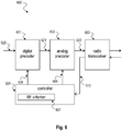
- Fig. 5 is a block diagram illustrating a base station 500 for serving multiple user terminals according to the disclosure.
- the base station 500 is an exemplary representation of the base station 210 or access point described above with respect to Figures 2 and 3 or of the base station or access point 110 described above with respect to Fig. 1 .
- the base station 500 can serve (i.e. communicate with) multiple user terminals, e.g. user terminals 600 as described below with respect to Fig. 6 .
- the base station 500 includes a digital precoder 501 and an analog precoder 502 which are configured to precode a first training signal 510.
- the digital precoder 501 may correspond to the baseband precoder 211 described above with respect to Fig. 2 .
- the analog precoder 502 may correspond to the RF precoder 213 described above with respect to Fig. 2 .
- the base station 500 further includes a radio transceiver 503 configured to transmit the precoded first training signal 512 and to receive a precoded second training signal 622 upon transmission of the precoded first training signal 512.
- the precoded second training signal 622 may be received from a user terminal 600 as described below with respect to Fig. 6 .
- the radio transceiver 503 may correspond to the antenna array 214 or the antenna ports of the antenna array 214 described above with respect to Fig. 2 .
- the base station 500 further includes a controller 504 configured to adjust 506 a precoding of the digital precoder 501 based on processing of the second training signal 622 with respect to a normalization criterion, e.g. as described above with respect to Figures 2 and 3 .
- the controller 504 is further configured to adjust 505 a precoding of the analog precoder 502 based on processing of the second training signal 622 with respect to a multi-user beamforming criterion 507, e.g. as described above with respect to Figures 2 and 3 .
- the controller 504 may adjust 505 the precoding of the analog precoder 502 based on a codebook selection according to the multi-user beamforming criterion, e.g. as described above with respect to Figures 2 and 3 .
- the controller 504 may adjust 505 the precoding of the analog precoder 502 based on beam steering according to the multi-user beamforming criterion.
- the beam steering may be based on directions of departure of most-significant multipath components transmitted by the transceiver, e.g. as described above with respect to Figures 2 and 3 .
- the beam steering may be based on selecting beams according to a signal energy criterion.
- the multi-user beamforming criterion 507 may include sum of beamforming gains and/or Zero-Forcing (ZF) sum-rate, for example, or other criteria.
- the multi-user beamforming criterion 507 may be based on a plurality of analog beams transmitted by the radio transceiver 503 to the multiple user terminals.
- the controller 504 may adjust 506 the precoding of the digital precoder 501 based on a ping-pong process with respect to transmissions and receptions of the radio transceiver 503, e.g. as described above with respect to Figures 2 and 3 .
- the radio transceiver 503 may transmit a respective transmission based on an adjustment of the digital precoder 501 with respect to a preceding reception, e.g. as described above with respect to Figure 3 .
- the controller 504 may adjust 506 the precoding of the digital precoder 501 based on conjugation and normalization of the second training signal, e.g. as described above with respect to Figures 2 and 3 .
- the normalization may comprise correlation with a known pilot signal.
- the controller 504 may initialize the analog precoder 502 to a state that enables the analog precoder 502 scanning all directions, e.g. as described above with respect to Figures 2 and 3 .
- the controller 504 may for example initialize the digital precoder 501 randomly.
- the second training signal 622 may comprise respective transmissions from multiple user terminals. These respective transmissions may comprise mutually orthogonal pilot sequences, e.g. as described above with respect to Figures 2 and 3 .
- Fig. 6 is a block diagram illustrating a user terminal 600 according to the disclosure.
- the user terminal 600 is an exemplary representation of the user terminals 220, 330 described above with respect to Figures 2 and 3 or of the user terminals 121, 122 described above with respect to Fig. 1 .
- the user terminal 600 includes a digital precoder 601 and an analog precoder 602 which are configured to precode a second training signal 620.
- the digital precoder 601 may correspond to the baseband combiner 221 or baseband precoder described above with respect to Fig. 2 .
- the analog precoder 602 may correspond to the RF combiner 223 or RF precoder described above with respect to Fig. 2 .
- the user terminal 600 includes a radio transceiver 603 configured to transmit the precoded second training signal 622 and to receive a precoded first training signal 512 in response to transmission of the precoded second training signal 622.
- the precoded first training signal 512 may be received from a base station 500 described above with respect to Fig. 5 .
- the radio transceiver 603 may correspond to the antenna array 224 or the antenna ports of the antenna array 224 described above with respect to Fig. 2 .
- the user terminal 600 further includes a controller 607 configured to adjust 606 a precoding of the digital precoder 601 based on processing of the first training signal 512 with respect to a normalization criterion, e.g. as described above with respect to Figures 2 and 3 .
- the controller 607 is configured to adjust 605 a precoding of the analog precoder 602 based on processing of the first training signal 512 with respect to a beamforming criterion 607, e.g. as described above with respect to Figures 2 and 3 .
- the controller 604 may adjust 605 the precoding of the analog precoder 602 based on a codebook selection according to the beamforming criterion, e.g. as described above with respect to Figures 2 and 3 .
- the controller 604 may adjust 605 the precoding of the analog precoder 602 based on beam steering of the first training signal 512.
- the beam steering may be based on directions of departure of most-significant multipath components transmitted by the transceiver 603, e.g. as described above with respect to Figures 2 and 3 .
- the beam steering may be based on selecting beams according to a signal energy criterion.
- the controller 604 may adjust 606 the precoding of the digital precoder 601 based on a ping-pong process with respect to transmissions and receptions of the radio transceiver 603, e.g. as described above with respect to Figures 2 and 3 .
- the radio transceiver 603 may transmit a respective transmission based on an adjustment 606 of the digital precoder 601 with respect to a preceding reception, e.g. as described above with respect to Figure 3 .
- the controller 604 may adjust 606 the precoding of the digital precoder 601 based on conjugation and normalization of the first training signal 512, e.g. as described above with respect to Figures 2 and 3 .
- the normalization may comprise correlation with a known pilot signal, e.g. as described above with respect to Figures 2 and 3 .
- the controller 604 may initialize the analog precoder 602 to a state that enables the analog precoder 602 scanning all directions, e.g. as described above with respect to Figures 2 and 3 .
- the controller 604 may initialize the digital precoder 601 randomly.
- Fig. 7 is a schematic diagram illustrating a multi-user precoding method 700 according to the disclosure.
- the method 700 includes precoding 701, by a digital precoder and an analog precoder, e.g. a digital precoder 501 and an analog precoder 502 as described above with respect to Figure 5 , a first training signal.
- a digital precoder and an analog precoder e.g. a digital precoder 501 and an analog precoder 502 as described above with respect to Figure 5 .
- the method 700 includes transmitting 702 the precoded first training signal by a radio transceiver, e.g. a radio transceiver 503 as described above with respect to Figure 5 .
- the method 700 includes receiving 703 a precoded second training signal by the radio transceiver upon transmission of the precoded first training signal, e.g. as described above with respect to Figures 2 , 3 and 5 .
- the method 700 further includes adjusting 704 a precoding of the digital precoder based on processing the second training signal with respect to a normalization criterion and adjusting a precoding of the analog precoder based on processing the second training signal with respect to a multi-user beamforming criterion, e.g. as described above with respect to Figures 2 , 3 and 5 .
- the method 700 may further include adjusting the precoding of the analog precoder based on a codebook selection according to the multi-user beamforming criterion, e.g. as described above with respect to Figures 2 , 3 and 5 .
- the method 700 may further include adjusting the precoding of the analog precoder based on beam steering according to the multi-user beamforming criterion.
- the beam steering may be based on directions of departure of most-significant multipath components transmitted by the transceiver.
- the beam steering may be based on selecting beams according to a signal energy criterion.
- the multi-user beamforming criterion may comprise one of the following: sum of beamforming gains; or Zero-Forcing (ZF) sum-rate.
- the multi-user beamforming criterion may be based on a plurality of analog beams transmitted by the radio transceiver to the multiple user terminals, e.g. as described above with respect to Figures 2 , 3 and 5 .
- the method 700 may further include adjusting the precoding of the digital precoder based on a ping-pong process with respect to transmissions and receptions of the radio transceiver.
- the method 700 may further include transmitting, by the radio receiver, a respective transmission based on an adjustment of the digital precoder with respect to a preceding reception.
- the method 700 may further include adjusting the precoding of the digital precoder based on conjugation and normalization of the second training signal, e.g. as described above with respect to Figures 2 , 3 and 5 .
- the normalization may comprise correlation with a known pilot signal.
- the method 700 may further include initializing the analog precoder to a state that enables the analog precoder scanning all directions.
- the method 700 may further include initializing the digital precoder randomly.
- the second training signal may comprise respective transmissions from multiple user terminals.
- the respective transmissions may comprise mutually orthogonal pilot sequences, e.g. as described above with respect to Figures 2 , 3 and 5 .
- DSP Digital Signal Processors
- ASIC application specific integrated circuit
- Embodiments described in this disclosure can be implemented in digital electronic circuitry, or in computer hardware, firmware, software, or in combinations thereof, e.g. in available hardware of mobile devices or in new hardware dedicated for processing the methods described herein.
- the present disclosure also supports a computer program product including computer executable code or computer executable instructions that, when executed, causes at least one computer to execute the performing and computing blocks described herein, in particular the methods 300 and 700 described above with respect to Figs. 3 and 7 and the computing blocks described above with respect to Figures 2 , 5 and 6 .
- a computer program product may include a non-transient readable storage medium storing program code thereon for use by a processor, the program code comprising instructions for performing the methods or the computing blocks as described above.
Description
- The disclosure relates to techniques for beamforming in multi-user systems. The disclosure particularly relates to a base station for serving multiple user terminals, a corresponding user terminal and a multi-user precoding method. The disclosure further relates to a ping-pong beam training method for multi-user MIMO systems with hybrid digital-analog antenna arrays.
- Beamforming between MIMO (multiple-input multiple-output) wireless transceivers enables SNR (signal-to-noise ratio) gains for single-stream transmission that are proportional to the number of antennas used. The basic principle is to linearly pre-code the transmitted signal in such a way that it can be coherently combined at the receive antenna array. In a multi-terminal or user system, spectral efficiency is generally optimized when the access point communicates with multiple terminals simultaneously exploiting the spatial degrees of freedom provided by the presence of multiple antennas at both the transmitter and the receiver. The design of multi-terminal transceivers (especially in the downlink direction) conventionally requires the whole set of multi-terminal channel coefficients, which is a costly operation, potentially bringing non sustainable delays in the communication. The disclosure presents techniques for efficient communication in multi-terminal or user beamforming systems.
EP 2 894 796 A1US 2017/0317735 A1 describes an iterative procedure relying on a ping-pong transmission between two antenna arrays to determine beamforming weights at a base station and a user equipment. - The accompanying drawings are included to provide a further understanding of embodiments and are incorporated in and constitute a part of this specification. The drawings illustrate embodiments and together with the description serve to explain principles of embodiments. Other embodiments and many of the intended advantages of embodiments will be readily appreciated as they become better understood by reference to the following detailed description.
-
Fig. 1 is an exemplary schematic diagram illustrating amulti-terminal beamforming system 100. -
Fig. 2 is a block diagram illustrating an exemplarymulti-user beamforming system 200 according to the disclosure. -
Fig. 3 is a schematic diagram illustrating a ping-pongbeam training method 300 according to the disclosure in a multi-user system. -
Fig. 4 is a performance diagram 400 illustrating exemplary performance ofmulti-user beamforming channel state information 403. -
Fig. 5 is a block diagram illustrating anexemplary base station 500 for serving multiple user terminals according to the disclosure. -
Fig. 6 is a block diagram illustrating anexemplary user terminal 600 according to the disclosure. -
Fig. 7 is a schematic diagram illustrating an exemplarymulti-user precoding method 700 according to the disclosure. - In the following detailed description, reference is made to the accompanying drawings, which form a part thereof, and in which is shown by way of illustration specific aspects in which the invention may be practiced. It is understood that other aspects may be utilized and structural or logical changes may be made without departing from the scope of the present invention. The following detailed description, therefore, is not to be taken in a limiting sense, and the scope of the present invention is defined by the appended claims.
- The following terms, abbreviations and notations will be used herein:
- BF:
- Beamforming
- MIMO:
- Multiple-Input Multiple-Output
- MU-MIMO:
- Multi-User MIMO
- CSI:
- Channel State Information
- SNR:
- Signal-to-Noise Ratio
- SVD:
- Singular Value Decomposition
- BS:
- Base Station
- ZF:
- Zero Forcing
- RF:
- Radio Frequency
- BB:
- Baseband
- It is understood that comments made in connection with a described method may also hold true for a corresponding device configured to perform the method and vice versa. For example, if a specific method step is described, a corresponding device may include a unit to perform the described method step, even if such a unit is not explicitly described or illustrated in the figures. Further, it is understood that the features of the various exemplary aspects described herein may be combined with each other, unless specifically noted otherwise.
- The techniques described herein may be implemented in wireless communication networks, in particular communication networks based on mobile communication standards such as LTE, in particular LTE-A and/or OFDM and successor standards such as 5G. The methods are also applicable for high speed communication standards from the 802.11 family according to the WiFi alliance, e.g. 802.11ad and successor standards. The methods and devices described below may be implemented in electronic devices such as access points and base stations or cellular handsets and mobile or wireless devices. The described devices may include integrated circuits and/or passives and may be manufactured according to various technologies. For example, the circuits may be designed as logic integrated circuits, analog integrated circuits, mixed signal integrated circuits, optical circuits, memory circuits and/or integrated passives.
- In the following, embodiments are described with reference to the drawings, wherein like reference numerals are generally utilized to refer to like elements throughout. In the following description, for purposes of explanation, numerous specific details are set forth in order to provide a thorough understanding of one or more aspects of embodiments. However, it may be evident to a person skilled in the art that one or more aspects of the embodiments may be practiced with a lesser degree of these specific details. The following description is therefore not to be taken in a limiting sense.
- The various aspects summarized may be embodied in various forms. The following description shows by way of illustration various combinations and configurations in which the aspects may be practiced. It is understood that the described aspects and/or embodiments are merely examples, and that other aspects and/or embodiments may be utilized and structural and functional modifications may be made without departing from the scope of the present disclosure.
-
Fig. 1 is a schematic diagram illustrating amulti-terminal beamforming system 100. Thebeamforming system 100 includes a radio cell in which a base station oraccess point 110 providesbeamformed communication 111 tomultiple terminals 121, 122. - Beamforming between MIMO wireless transceivers (of base station or
access point 110 anduser terminals 121, 122 as shown inFig. 1 ) enables SNR gains for single-stream transmission that are proportional to the number of antennas used. In a nutshell, the basic principle is to linearly pre-code the transmitted signal in such a way that it can be coherently combined at the receive antenna array. The SNR gain obtained this way is maximum when the pre-coder and combiner are calculated based on the singular vectors of the MIMO channel matrix associated to its largest singular value. Hence, optimal beamforming requires full channel state information (CSI) and computationally demanding singular value decomposition (SVD) of the channel matrix. To avoid the need for acquisition of the CSI and the subsequent SVD, ping-pong beam training methods can be applied, in which the MIMO transceivers perform alternate transmissions of training data while setting their pre-coders via simple conjugation and normalization operations. Due to the wireless channel reciprocity, this strategy implicitly implements a power iteration method that leads to the pre-coders at both transceivers converging to the left and right singular vectors of the channel, hence approaching the optimal beamforming gain. - The cost and power consumption of antenna arrays grows with the number of elements and the bandwidth and carrier frequency of the system, making digitally controlled antenna arrays infeasible for millimeter Wave (mmWave) frequency systems. Hybrid digital-analog antenna arrays, in which the array is steered using analog phase shifters and only a few digitally modulated radiofrequency chains, can reduce this cost. However, the presence of the analog phase shifters prevents the use of SVD-based beamforming solutions, as full CSI acquisition becomes infeasible and direct applicability of ping-pong beam training methods. Instead, methods for selecting the pre-coders based on a search over a hierarchical codebook can be applied, with or without partial CSI acquisition, e.g. angles of arrival/departure of multipath components.
- In a multi-terminal system as shown for example in
Fig. 1 , spectral efficiency is generally optimized when theaccess point 110 communicates withmultiple terminals 121, 122 simultaneously exploiting the spatial degrees of freedom provided by the presence of multiple antennas at both the transmitter and the receiver. The design of multi-terminal transceivers (especially in the downlink direction) conventionally requires the whole set of multi-terminal channel coefficients, which is a costly operation, potentially bringing non sustainable delays in the communication. Instead, it is more efficient to estimate the left and right singular vectors of each terminal 121, 122 in a training procedure and build multi-terminal transceivers that are based on this limited CSI. One specificity is that the analog beamformers at theaccess point 110 are common to allterminals 121, 122, necessitating a joint design of the multi-terminal training procedure. - The disclosure addresses the problem of estimating the left and right singular vectors in a multi-terminal system, e.g. as shown in
Fig. 1 , where all thedevices multi-user system 100, e.g. as shown inFig. 1 , in which thebase station 110 and themultiple users 121, 122 are equipped with hybrid digital-analog antenna arrays. The disclosure particularly addresses downlink communication of abase station 110 with multiple users (i.e. user terminals 121, 122) which are served over the same channel resources, multiplexed in the spatial dimension (i.e. a multi-user MIMO (MU-MIMO) system). The disclosed method yields a close-to-optimal hybrid (analog and digital) precoder for MU-MIMO systems. The multiple users may share the same analog beam. The procedure relies on ping-pong transmission and the method to update both the analog and the digital beams is described in the following, in particular below with respect toFigures 2 and3 . - The disclosure presents a novel ping-pong beam training method in a multi-terminal system that circumvents the limitations due to the hybrid structure of the antenna array. The presented method is based on alternate transmissions of training data between the
access points 110 and themultiple terminal 121, 122 all with hybrid antenna arrays. - The method distinguishes between uplink and downlink transmission. Based on uplink training, the
access point 110 updates the digital and analog pre-coders that are subsequently used to transmit the downlink training with a two-step procedure: 1) the digital pre-coder used for transmission to each terminal 121, 122 is set following the conjugation and normalization operations as described below with respect toFigures 2 and3 in more detail; 2) the analog pre-coders are computed by selecting elements of a hierarchical codebook according to a multi-user criterion. As the analog beamformers are common to all the terminals, the resulting multi-terminal beam steering finds a compromise among the directions of departure of the channel's most significant multipath components of the different terminals. - Based on downlink training, one given terminal, e.g. terminal 121 shown in
Fig. 1 updates the digital and analog pre-coders that are subsequently used to transmit the uplink training with a two-step procedure: 1) the digital pre-coder used for transmission from each terminal 121, 122 is set following the conjugation and normalization operations as described below with respect toFigures 2 and3 in more detail; 2) the analog pre-coders are computed by selecting elements of a hierarchical codebook that steer the transmitted signal towards the directions of departure of the channel's most significant multipath components. - The resulting scheme has very low complexity, as it avoids the need for full CSI acquisition, and converges with only a few back-and-forth transmissions. Performance-wise, the disclosed beam training method achieves higher beamforming gain than the original scheme devised for digital arrays at low SNR ranges, while performing very closely to the optimal SVD-based beamformers at the high SNR regime as illustrated below with respect to
Figure 4 . - The computational complexity of the method is negligible compared to other receiver operations and compared to alternative beamforming methods. The digital beamformers/combiners are computed by conjugating the digital signal received in the previous transmission and normalizing the resulting vector to fulfill a power constraint. The analog precoders/combiners are chosen from a predefined codebook which is designed offline. The search in the codebook is performed by simply sorting in descending order of magnitude the entries of a normalized version of the received signal vector.
- The method can be used to enhance both the terminal and the cell throughput in systems equipped with hybrid antenna arrays, e.g. 5G systems operating above 6 GHz, for which 3GPP mandates the usage of cooperative beam management procedures.
-
Fig. 2 is a block diagram illustrating amulti-user beamforming system 200 according to the disclosure. The left side block ofFig. 2 represents thebase station 210 while the right side block ofFig. 2 represents themulti-user terminals 220 exemplary depicting the terminal of user k. - In the base station 210 a transmit signal 201 can pass the
baseband precoder 211, a plurality ofRF chains RF precoder 213 before being transmitted by an antenna array 214 over a MIMO channel Hk . Each RF chain is coupled to a respectiveRF precoder group combination logics - In the
user terminal 220 the transmit signal can be received via anantenna array 224 which is coupled to anRF combiner 223 for combining the RF signals received by theantenna array 224. TheRF combiner 223 is partitioned in groups of RF beamformers 223a, 223b withrespective combiners RF chains RF chains baseband combiner 221 to provide an estimate 202 of the transmit signal 201. -
Fig. 2 exemplarily depicts a system with oneBS 210 andmultiple terminals 220, equipped with uniformlinear arrays 214, 224 with NBS and Nk elements at terminal k, 220 separated by a distance d = λ/2, each having

RF chains - The method is based on a sequence of alternate transmissions of training sequences between the
BS 210 and theterminals Fig. 3 . A training procedure can be performed for each access point-terminal link based on a pilot sequence. The pilot sequences are assumed to be mutually orthogonal so that the training signals of each terminal can be easily separated (based on a correlation with the appropriate pilot sequence). - In the downlink direction, the
BS 210 can perform simultaneous transmissions to allK users 220 using orthogonal training sequences. After correlating with the pilot sequence, the signal received at thek th terminal 220 reads
- This signal is conjugated and normalized to be used as the baseband precoder for user k( wk ) for the uplink transmission. After the downlink transmission, the
BS 210 updates its RF precoder 213 as indicated further below. Upon reception of the downlink training sequence, allK users 220 can simultaneously transmit their orthogonal training sequences using their updated baseband precoders. After this uplink transmission, theusers 220 can update their RF precoders as indicated further below. - To perform the training procedure for
terminal k 220, the received signal at theBS 210 is correlated by the pilot sequence ofterminal k 220. After proper scaling, the received signal is
baseband precoder 213 used by theBS 210 for user k( wBSk ). - In the equations above, F BS and W BS,k denote the RF precoder 213 at the BS 210 (common to all terminals 220) and baseband (BB) precoders 211 at the
BS 210. F k and W k denote the RF precoder 223 and baseband (BB) precoders 221 atterminal k 220, with n BS,k and n k representing AWGN vectors at theBS 210 and at terminal k 220 (it is the equivalent noise after normalized correlation). While the BB precoders 211, 221 can take any values in the complex domain

-
Fig. 3 is a schematic diagram illustrating a ping-pongbeam training method 300 according to the disclosure in a multi-user system. -
Fig. 3 illustrates a method between abase station 210 as described above with respect toFig. 2 and an exemplary number of two users terminals, e.g. auser terminal k 220 as described above with respect toFig. 2 and another user terminal k' 330. In the method multiple transmissions between thebase station 210 and theuser terminals base station 210 and theuser terminals BB precoders RF precoders base station 210 anduser terminal k 220 theexemplary transmissions base station 210 and user terminal k' 330 theexemplary transmissions - As detailed in
Fig. 3 , the RF precoders 213, 223 of theBS 210 and of allusers 220 are initialized to a state in which they scan all directions, and the BB precoder 211 of the first device to transmit (theBS 210 in the figure) is initialized randomly. After this, the alternate transmission of training sequences starts. After each reception and normalized correlation with the pilot sequence ofterminal k 220, the transceiver performs complex conjugation of the resulting signal. The resulting vector is, after normalization, set to be the new BB precoder, which is immediately used to transmit a new pilot to the other device. Immediately after, the device updates its RF precoder using the information obtained at the latest reception, so that the updated RF precoder can be used in for the coming reception. - The characteristic of this procedure is the update of the RF precoders in a multi-terminal communication with the specificity that there are no distinct RF precoders to communicate to one given terminal but rather RF precoders that are used in common. The columns of the RF precoders F BS and F k are restricted to belong to a hierarchical, directional codebook. In the following, an example of implementation of the method is described with an example codebook. Note that other codebooks following similar structure can be used as well.
- In the Example of implementation the codebook definition is illustrated for transceiver BS, and an analogous codebook is used for the transceiver of terminal k. A codebook CBS is considered which is composed of


- Using the codebook defined above, a particular instance of the disclosed method can be described in
Algorithm 1 shown below.
- The RF precoders for both devices are initialized by using the elements in the lowest level of the codebook (j = 1), and a random BB precoder is selected for each of the K users at the BS (without loss of generality, the training procedure is initialized at the BS). Then, the sequence of alternate pilot transmissions starts. The BB precoders are updated by conjugation and normalization operations (lines 5-6, 14-15, and 22-23 in Algorithm 1), while two columns of the RF precoder are updated each time the routines in
Algorithm 2 shown below are invoked. The RF precoders at the BS are updated according to a criterion that is different from the one used to update the RF precoders at the terminal side.
- The BS RF precoder update is described in the routine UPD. BS ANALOG PRECODER in
Algorithm 2 requires further explanation. First, the columns of the RF precoder are sorted according to a specific sorting criterion. After this, two columns are selected: nmax denotes the best column and nmin the worst column, according to the sorting criterion. Both columns are removed from the codebook and replaced by elements of the codebook belonging to one level higher than column nmax, and pointing at two directions around which nmax was pointing. This operation steers the array in directions that are determined according to the design criterion. At the BS, the beam selection finds a compromise to serve multiple terminals through a common beam according to a multi-terminal design criterion. For the results presented below inFig. 4 , two different criteria were evaluated. One of them (sum of BF gains) simply sorts the columns of the precoder following the sum of signal energies received from all K users. The other criterion (ZF sum-rate) evaluates the contribution of each precoder column to the achievable sum-rate that the system would obtain if the BS used a zero-forcing (ZF) BB precoder; the columns are then sorted in descending order of contribution to the system's estimated sum-rate. Note that other criteria for the selection of the BS RF precoder columns may be used as well, depending on the transmission strategy for the BS. - As each terminal possesses its own RF precoder, at the user side the beams can be selected according to a simple received signal energy criterion described in the routine UPD.UE ANALOG PRECODER in
Algorithm 2. Generally speaking, the beams are steered along directions over which most signal is received with beams that have increasing directivity as the iterations of the method progress. - The characteristic of the presented method lies in the inclusion of the RF precoder updates into the sequence of alternate transmissions in a communication between a BS and multiple terminals. The described update of the RF precoders enables the use of the method with hybrid digital-analog antenna arrays for a multi-terminal communication system.
- The above description presents the method in its simplest form. In this way, it can be used for acquisition of beamformer before the transceivers start exchanging data. While only pilot transmissions are considered here, the method can be used in other contexts. The basic requirement is simply that approximate reciprocity of the channel is kept, and that the channel matrix does not vary too fast.
- Other possible implementations of the method include:
- Schemes in which data transmissions are included in between the pilot transmissions.
- Implementations in a data-aided manner are also possible after the first few iterations (once the effective SNR at reception is large enough to successfully detect data symbols).
- For slowly changing channels, the method can be used to track the channel variations over time.
- For channels with faster variations, implementations in which a fallback option to low-level RF precoders when signal energy decreases is enabled can provide protection against blockage, deep fades, etc.
-
Fig. 4 is a performance diagram 400 illustrating exemplary performance ofmulti-user beamforming channel state information 403. - The performance of the disclosed method (Multi-Terminal Hybrid PPBT) can be shown by evaluating the multi-terminal sum rate at each iteration of the training procedure. An iteration comprises one transmission/ reception of either the
access point 210 or themultiple terminals perfect CSI 403 and fully digital antenna arrays which uses fully digital arrays. - A system with one BS (indexed as BS) and K terminals (indexed by k) is considered. All devices are equipped with uniform linear arrays with NBs and Nk elements separated by a distance d = λ/2, each of them having


- Random realizations of the MIMO channel matrix of each terminal are drawn according to the model


- The performance for two different system sizes and several SNRs is depicted in
Fig. 4 .Graph 401 illustrates the disclosed method based on sum BF gains.Graph 402 illustrates the disclosed method based on zero-forcing sum rate.Graph 403 illustrates a reference system with perfect CSI and digital ZF. -
Fig. 5 is a block diagram illustrating abase station 500 for serving multiple user terminals according to the disclosure. Thebase station 500 is an exemplary representation of thebase station 210 or access point described above with respect toFigures 2 and3 or of the base station oraccess point 110 described above with respect toFig. 1 . - The
base station 500 can serve (i.e. communicate with) multiple user terminals,e.g. user terminals 600 as described below with respect toFig. 6 . Thebase station 500 includes adigital precoder 501 and ananalog precoder 502 which are configured to precode afirst training signal 510. Thedigital precoder 501 may correspond to thebaseband precoder 211 described above with respect toFig. 2 . Theanalog precoder 502 may correspond to the RF precoder 213 described above with respect toFig. 2 . Thebase station 500 further includes aradio transceiver 503 configured to transmit the precodedfirst training signal 512 and to receive a precodedsecond training signal 622 upon transmission of the precodedfirst training signal 512. The precodedsecond training signal 622 may be received from auser terminal 600 as described below with respect toFig. 6 . Theradio transceiver 503 may correspond to the antenna array 214 or the antenna ports of the antenna array 214 described above with respect toFig. 2 . - The
base station 500 further includes acontroller 504 configured to adjust 506 a precoding of thedigital precoder 501 based on processing of thesecond training signal 622 with respect to a normalization criterion, e.g. as described above with respect toFigures 2 and3 . Thecontroller 504 is further configured to adjust 505 a precoding of theanalog precoder 502 based on processing of thesecond training signal 622 with respect to amulti-user beamforming criterion 507, e.g. as described above with respect toFigures 2 and3 . - The
controller 504 may adjust 505 the precoding of theanalog precoder 502 based on a codebook selection according to the multi-user beamforming criterion, e.g. as described above with respect toFigures 2 and3 . Thecontroller 504 may adjust 505 the precoding of theanalog precoder 502 based on beam steering according to the multi-user beamforming criterion. The beam steering may be based on directions of departure of most-significant multipath components transmitted by the transceiver, e.g. as described above with respect toFigures 2 and3 . The beam steering may be based on selecting beams according to a signal energy criterion. - The
multi-user beamforming criterion 507 may include sum of beamforming gains and/or Zero-Forcing (ZF) sum-rate, for example, or other criteria.
Themulti-user beamforming criterion 507 may be based on a plurality of analog beams transmitted by theradio transceiver 503 to the multiple user terminals. - The
controller 504 may adjust 506 the precoding of thedigital precoder 501 based on a ping-pong process with respect to transmissions and receptions of theradio transceiver 503, e.g. as described above with respect toFigures 2 and3 . Theradio transceiver 503 may transmit a respective transmission based on an adjustment of thedigital precoder 501 with respect to a preceding reception, e.g. as described above with respect toFigure 3 . - The
controller 504 may adjust 506 the precoding of thedigital precoder 501 based on conjugation and normalization of the second training signal, e.g. as described above with respect toFigures 2 and3 . The normalization may comprise correlation with a known pilot signal. - The
controller 504 may initialize theanalog precoder 502 to a state that enables theanalog precoder 502 scanning all directions, e.g. as described above with respect toFigures 2 and3 . Thecontroller 504 may for example initialize thedigital precoder 501 randomly. - The
second training signal 622 may comprise respective transmissions from multiple user terminals. These respective transmissions may comprise mutually orthogonal pilot sequences, e.g. as described above with respect toFigures 2 and3 . -
Fig. 6 is a block diagram illustrating auser terminal 600 according to the disclosure. Theuser terminal 600 is an exemplary representation of theuser terminals Figures 2 and3 or of theuser terminals 121, 122 described above with respect toFig. 1 . - The
user terminal 600 includes adigital precoder 601 and ananalog precoder 602 which are configured to precode asecond training signal 620. Thedigital precoder 601 may correspond to thebaseband combiner 221 or baseband precoder described above with respect toFig. 2 . Theanalog precoder 602 may correspond to theRF combiner 223 or RF precoder described above with respect toFig. 2 . - The
user terminal 600 includes aradio transceiver 603 configured to transmit the precodedsecond training signal 622 and to receive a precodedfirst training signal 512 in response to transmission of the precodedsecond training signal 622. The precodedfirst training signal 512 may be received from abase station 500 described above with respect toFig. 5 . Theradio transceiver 603 may correspond to theantenna array 224 or the antenna ports of theantenna array 224 described above with respect toFig. 2 . - The
user terminal 600 further includes acontroller 607 configured to adjust 606 a precoding of thedigital precoder 601 based on processing of thefirst training signal 512 with respect to a normalization criterion, e.g. as described above with respect toFigures 2 and3 . Thecontroller 607 is configured to adjust 605 a precoding of theanalog precoder 602 based on processing of thefirst training signal 512 with respect to abeamforming criterion 607, e.g. as described above with respect toFigures 2 and3 . - The
controller 604 may adjust 605 the precoding of theanalog precoder 602 based on a codebook selection according to the beamforming criterion, e.g. as described above with respect toFigures 2 and3 . Thecontroller 604 may adjust 605 the precoding of theanalog precoder 602 based on beam steering of thefirst training signal 512. The beam steering may be based on directions of departure of most-significant multipath components transmitted by thetransceiver 603, e.g. as described above with respect toFigures 2 and3 . The beam steering may be based on selecting beams according to a signal energy criterion. - The
controller 604 may adjust 606 the precoding of thedigital precoder 601 based on a ping-pong process with respect to transmissions and receptions of theradio transceiver 603, e.g. as described above with respect toFigures 2 and3 . Theradio transceiver 603 may transmit a respective transmission based on anadjustment 606 of thedigital precoder 601 with respect to a preceding reception, e.g. as described above with respect toFigure 3 . - The
controller 604 may adjust 606 the precoding of thedigital precoder 601 based on conjugation and normalization of thefirst training signal 512, e.g. as described above with respect toFigures 2 and3 . The normalization may comprise correlation with a known pilot signal, e.g. as described above with respect toFigures 2 and3 . - The
controller 604 may initialize theanalog precoder 602 to a state that enables theanalog precoder 602 scanning all directions, e.g. as described above with respect toFigures 2 and3 . For example, thecontroller 604 may initialize thedigital precoder 601 randomly. -
Fig. 7 is a schematic diagram illustrating amulti-user precoding method 700 according to the disclosure. - The
method 700 includesprecoding 701, by a digital precoder and an analog precoder, e.g. adigital precoder 501 and ananalog precoder 502 as described above with respect toFigure 5 , a first training signal. - The
method 700 includes transmitting 702 the precoded first training signal by a radio transceiver, e.g. aradio transceiver 503 as described above with respect toFigure 5 . Themethod 700 includes receiving 703 a precoded second training signal by the radio transceiver upon transmission of the precoded first training signal, e.g. as described above with respect toFigures 2 ,3 and5 . - The
method 700 further includes adjusting 704 a precoding of the digital precoder based on processing the second training signal with respect to a normalization criterion and adjusting a precoding of the analog precoder based on processing the second training signal with respect to a multi-user beamforming criterion, e.g. as described above with respect toFigures 2 ,3 and5 . - The
method 700 may further include adjusting the precoding of the analog precoder based on a codebook selection according to the multi-user beamforming criterion, e.g. as described above with respect toFigures 2 ,3 and5 . Themethod 700 may further include adjusting the precoding of the analog precoder based on beam steering according to the multi-user beamforming criterion. The beam steering may be based on directions of departure of most-significant multipath components transmitted by the transceiver. The beam steering may be based on selecting beams according to a signal energy criterion. The multi-user beamforming criterion may comprise one of the following: sum of beamforming gains; or Zero-Forcing (ZF) sum-rate. The multi-user beamforming criterion may be based on a plurality of analog beams transmitted by the radio transceiver to the multiple user terminals, e.g. as described above with respect toFigures 2 ,3 and5 . - The
method 700 may further include adjusting the precoding of the digital precoder based on a ping-pong process with respect to transmissions and receptions of the radio transceiver. Themethod 700 may further include transmitting, by the radio receiver, a respective transmission based on an adjustment of the digital precoder with respect to a preceding reception. Themethod 700 may further include adjusting the precoding of the digital precoder based on conjugation and normalization of the second training signal, e.g. as described above with respect toFigures 2 ,3 and5 . - The normalization may comprise correlation with a known pilot signal. The
method 700 may further include initializing the analog precoder to a state that enables the analog precoder scanning all directions. Themethod 700 may further include initializing the digital precoder randomly. The second training signal may comprise respective transmissions from multiple user terminals. The respective transmissions may comprise mutually orthogonal pilot sequences, e.g. as described above with respect toFigures 2 ,3 and5 . - The devices and systems described in this disclosure may be implemented as Digital Signal Processors (DSP), microcontrollers or any other side-processor or hardware circuit on a chip or an application specific integrated circuit (ASIC).
- Embodiments described in this disclosure can be implemented in digital electronic circuitry, or in computer hardware, firmware, software, or in combinations thereof, e.g. in available hardware of mobile devices or in new hardware dedicated for processing the methods described herein.
- The present disclosure also supports a computer program product including computer executable code or computer executable instructions that, when executed, causes at least one computer to execute the performing and computing blocks described herein, in particular the
methods Figs. 3 and7 and the computing blocks described above with respect toFigures 2 ,5 and6 . Such a computer program product may include a non-transient readable storage medium storing program code thereon for use by a processor, the program code comprising instructions for performing the methods or the computing blocks as described above. - The invention is defined by the appended independent claims. Preferred embodiments of the invention are stipulated in the dependent claims. While several embodiments and/or numbered examples are disclosed in this description, the subject matter for which protection is sought is strictly and solely limited to those embodiments and/or examples encompassed by the scope of the appended claims. Embodiments and/or examples mentioned in the description that do not fall under the scope of the claims are only useful for understanding the invention.
- Example 1 is a base station for communication with multiple user terminals, the base station comprising: a digital precoder and an analog precoder which are configured to precode a first training signal; a radio transceiver configured to transmit the precoded first training signal and to receive a precoded second training signal upon transmission of the precoded first training signal; and a controller configured to adjust a precoding of the digital precoder based on processing of the second training signal with respect to a normalization criterion and to adjust a precoding of the analog precoder based on processing of the second training signal with respect to a multi-user beamforming criterion.
- In Example 2, the subject matter of Example 1 can optionally include that the controller is configured to adjust the precoding of the analog precoder based on a codebook selection according to the multi-user beamforming criterion.
- In Example 3, the subject matter of any one of Examples 1-2 can optionally include that the controller is configured to adjust the precoding of the analog precoder based on beam steering according to the multi-user beamforming criterion.
- In Example 4, the subject matter of Example 3 can optionally include that the beam steering is based on directions of departure of most-significant multipath components transmitted by the transceiver.
- In Example 5, the subject matter of Example 4 can optionally include that the beam steering is based on selecting beams according to a signal energy criterion.
- In Example 6, the subject matter of any one of Examples 1-5 can optionally include that the multi-user beamforming criterion comprises one of the following: sum of beamforming gains; or Zero-Forcing (ZF) sum-rate.
- In Example 7, the subject matter of any one of Examples 1-6 can optionally include that the multi-user beamforming criterion is based on a plurality of analog beams transmitted by the radio transceiver to the multiple user terminals.
- In Example 8, the subject matter of any one of Examples 1-7 can optionally include that the controller is configured to adjust the precoding of the digital precoder based on a ping-pong process with respect to transmissions and receptions of the radio transceiver.
- In Example 9, the subject matter of Example 8 can optionally include that the radio transceiver is configured to transmit a respective transmission based on an adjustment of the digital precoder with respect to a preceding reception.
- In Example 10, the subject matter of any one of Examples 1-9 can optionally include that the controller is configured to adjust the precoding of the digital precoder based on conjugation and normalization of the second training signal.
- In Example 11, the subject matter of Example 10 can optionally include that the normalization comprises correlation with a known pilot signal.
- In Example 12, the subject matter of any one of Examples 1-11 can optionally include that the controller is configured to initialize the analog precoder to a state that enables the analog precoder scanning all directions.
- In Example 13, the subject matter of any one of Examples 1-12 can optionally include that the controller is configured to initialize the digital precoder randomly.
- In Example 14, the subject matter of any one of Examples 1-13 can optionally include that the second training signal comprises respective transmissions from multiple user terminals.
- In Example 15, the subject matter of Example 14 can optionally include that the respective transmissions comprise mutually orthogonal pilot sequences.
- Example 16 is a user terminal, comprising: a digital precoder and an analog precoder which are configured to precode a second training signal; a radio transceiver configured to transmit the precoded second training signal and to receive a precoded first training signal in response to transmission of the precoded second training signal; and a controller configured to adjust a precoding of the digital precoder based on processing of the first training signal with respect to a normalization criterion and to adjust a precoding of the analog precoder based on processing of the first training signal with respect to a beamforming criterion.
- In Example 17, the subject matter of Example 16 can optionally include that the controller is configured to adjust the precoding of the analog precoder based on a codebook selection according to the beamforming criterion.
- In Example 18, the subject matter of any one of Examples 16-17 can optionally include that the controller is configured to adjust the precoding of the analog precoder based on beam steering of the first training signal.
- In Example 19, the subject matter of Example 18 can optionally include that the beam steering is based on directions of departure of most-significant multipath components transmitted by the transceiver.
- In Example 20, the subject matter of Example 19 can optionally include that the beam steering is based on selecting beams according to a signal energy criterion.
- In Example 21, the subject matter of any one of Examples 16-20 can optionally include that the controller is configured to adjust the precoding of the digital precoder based on a ping-pong process with respect to transmissions and receptions of the radio transceiver.
- In Example 22, the subject matter of Example 20 can optionally include that the radio transceiver is configured to transmit a respective transmission based on an adjustment of the digital precoder with respect to a preceding reception.
- In Example 23, the subject matter of any one of Examples 16-22 can optionally include that the controller is configured to adjust the precoding of the digital precoder based on conjugation and normalization of the first training signal.
- In Example 24, the subject matter of Example 23 can optionally include that the normalization comprises correlation with a known pilot signal.
- In Example 25, the subject matter of any one of Examples 16-24 can optionally include that the controller is configured to initialize the analog precoder to a state that enables the analog precoder scanning all directions.
- In Example 26, the subject matter of any one of Examples 16-25 can optionally include that the controller is configured to initialize the digital precoder randomly.
- Example 27 is a multi-user MIMO system, comprising: a base station according to one of Examples 1 to 15; and a plurality of user terminals according to one of Examples 16 to 26.
- Example 28 is a multi-user precoding method, comprising: precoding, by a digital precoder and an analog precoder, a first training signal; transmitting the precoded first training signal by a radio transceiver; receiving a precoded second training signal by the radio transceiver upon transmission of the precoded first training signal; and adjusting a precoding of the digital precoder based on processing the second training signal with respect to a normalization criterion and adjusting a precoding of the analog precoder based on processing the second training signal with respect to a multi-user beamforming criterion.
- In Example 29, the subject matter of Example 28 can optionally include adjusting the precoding of the analog precoder based on a codebook selection according to the multi-user beamforming criterion.
- In Example 30, the subject matter of any one of Examples 28-29 can optionally include adjusting the precoding of the analog precoder based on beam steering according to the multi-user beamforming criterion.
- In Example 31, the subject matter of Example 30 can optionally include that the beam steering is based on directions of departure of most-significant multipath components transmitted by the transceiver.
- In Example 32, the subject matter of any one of Examples 30-31 can optionally include that the beam steering is based on selecting beams according to a signal energy criterion.
- In Example 33, the subject matter of any one of Examples 28-32 can optionally include that the multi-user beamforming criterion comprises one of the following: sum of beamforming gains; or Zero-Forcing (ZF) sum-rate.
- In Example 34, the subject matter of any one of Examples 28-33 can optionally include that the multi-user beamforming criterion is based on a plurality of analog beams transmitted by the radio transceiver to the multiple user terminals.
- In Example 35, the subject matter of any one of Examples 28-34 can optionally include adjusting the precoding of the digital precoder based on a ping-pong process with respect to transmissions and receptions of the radio transceiver.
- In Example 36, the subject matter of Example 35 can optionally include transmitting, by the radio receiver, a respective transmission based on an adjustment of the digital precoder with respect to a preceding reception.
- In Example 37, the subject matter of any one of Examples 28-36 can optionally include adjusting the precoding of the digital precoder based on conjugation and normalization of the second training signal.
- In Example 38, the subject matter of Example 37 can optionally include that the normalization comprises correlation with a known pilot signal.
- In Example 39, the subject matter of any one of Examples 28-38 can optionally include initializing the analog precoder to a state that enables the analog precoder scanning all directions.
- In Example 40, the subject matter of any one of Examples 28-39 can optionally include initializing the digital precoder randomly.
- In Example 41, the subject matter of any one of Examples 28-40 can optionally include that the second training signal comprises respective transmissions from multiple user terminals.
- In Example 42, the subject matter of Example 41 can optionally include that the respective transmissions comprise mutually orthogonal pilot sequences.
- Example 43 is a precoding method, comprising: precoding a second training signal by a digital precoder and an analog precoder; transmitting the precoded second training signal by a radio transceiver; receiving a precoded first training signal by the radio transceiver upon transmission of the precoded second training signal; and adjusting a precoding of the digital precoder based on processing the first training signal with respect to a normalization criterion and adjusting a precoding of the analog precoder based on processing the first training signal with respect to a beamforming criterion.
- In Example 44, the subject matter of Example 43 can optionally include adjusting the precoding of the analog precoder based on a codebook selection according to the beamforming criterion.
- In Example 45, the subject matter of any one of Examples 43-44 can optionally include adjusting the precoding of the analog precoder based on beam steering of the first training signal.
- In Example 46, the subject matter of Example 45 can optionally include that the beam steering is based on directions of departure of most-significant multipath components transmitted by the transceiver.
- In Example 47, the subject matter of Example 46 can optionally include that the beam steering is based on selecting beams according to a signal energy criterion.
- In Example 48, the subject matter of any one of Examples 43-47 can optionally include adjusting the precoding of the digital precoder based on a ping-pong process with respect to transmissions and receptions of the radio transceiver.
- In Example 49, the subject matter of Example 46 can optionally include transmitting, by the radio transceiver, a respective transmission based on an adjustment of the digital precoder with respect to a preceding reception.
- In Example 50, the subject matter of any one of Examples 43-49 can optionally include adjusting the precoding of the digital precoder based on conjugation and normalization of the first training signal.
- In Example 51, the subject matter of Example 50 can optionally include that the normalization comprises correlation of the first training signal with a known pilot signal.
- In Example 52, the subject matter of any one of Examples 43-51 can optionally include initializing the analog precoder to a state that enables the analog precoder scanning all directions.
- In Example 53, the subject matter of any one of Examples 43-52 can optionally include initializing the digital precoder randomly.
- Example 54 is a multi-user precoding device, comprising: means for precoding a first training signal by a digital precoder and an analog precoder; means for transmitting the precoded first training signal by a radio transceiver; means for receiving a precoded second training signal by the radio transceiver upon transmission of the precoded first training signal; and means for adjusting a precoding of the digital precoder based on processing the second training signal with respect to a normalization criterion and adjusting a precoding of the analog precoder based on processing the second training signal with respect to a multi-user beamforming criterion.
- In Example 55, the subject matter of Example 54 can optionally include means for adjusting the precoding of the analog precoder based on a codebook selection according to the multi-user beamforming criterion.
- Example 56 is a precoding system for serving multiple user terminals, the precoding system comprising: a digital precoder and an analog precoder component which are configured to precode a first training signal; a radio transceiver component configured to transmit the precoded first training signal and to receive a precoded second training signal upon transmission of the precoded first training signal; and a controller component configured to adjust a precoding of the digital precoder based on processing the second training signal with respect to a normalization criterion and to adjust a precoding of the analog precoder based on processing the second training signal with respect to a multi-user beamforming criterion.
- In Example 57, the subject matter of Example 56 can optionally include that the controller component is configured to adjust the precoding of the analog precoder based on a codebook selection according to the multi-user beamforming criterion.
- Example 58 is a computer readable non-transitory medium on which computer instructions are stored which, when executed by a computer, cause the computer to perform the method of any one of Examples 28 to 53.
- In addition, while a particular feature or aspect of the disclosure may have been disclosed with respect to only one of several implementations, such feature or aspect may be combined with one or more other features or aspects of the other implementations as may be desired and advantageous for any given or particular application. Furthermore, to the extent that the terms "include", "have", "with", or other variants thereof are used in either the detailed description or the claims, such terms are intended to be inclusive in a manner similar to the term "comprise". Furthermore, it is understood that aspects of the disclosure may be implemented in discrete circuits, partially integrated circuits or fully integrated circuits or programming means. Also, the terms "exemplary", "for example" and "e.g." are merely meant as an example, rather than the best or optimal.
- Although the elements in the following claims are recited in a particular sequence with corresponding labeling, unless the claim recitations otherwise imply a particular sequence for implementing some or all of those elements, those elements are not necessarily intended to be limited to being implemented in that particular sequence.
Claims (9)
- A base station for communication with multiple user terminals, the base station comprising:a digital precoder and an analog precoder which are configured to precode a first training signal;a radio transceiver configured to transmit the precoded first training signal and to receive a precoded second training signal upon transmission of the precoded first training signal; anda controller configuredto adjust a precoding of the digital precoder based on conjugation and normalization of the second training signal, wherein the digital precoder adjustment is based on a ping-pong process with respect to transmissions and receptions of the radio transceiver by adjusting the digital precoder with respect to a preceding reception, andto adjust a precoding of the analog precoder based on processing of the second training signal with respect to a multi-user beamforming criterion by updating the analog precoder with respect to the preceding reception based on a codebook selection according to the multi-user beamforming criterion and by including the analog precoder updates into the ping-pong process with respect to transmissions and receptions of the radio transceiver.
- The base station of claim 1,
wherein the controller is configured to adjust the precoding of the analog precoder based on beam steering according to the multi-user beamforming criterion. - The base station of claim 2,
wherein the beam steering is based on directions of departure of most-significant multipath components transmitted by the transceiver. - The base station of claim 3,
wherein the beam steering is based on selecting beams according to a signal energy criterion. - The base station of one of the preceding claims,
wherein the multi-user beamforming criterion comprises one of the following: sum of beamforming gains; or Zero-Forcing (ZF) sum-rate. - The base station of one of the preceding claims,
wherein the multi-user beamforming criterion is based on a plurality of analog beams transmitted by the radio transceiver to the multiple user terminals. - A user terminal, comprising:a digital precoder and an analog precoder which are configured to precode a second training signal;a radio transceiver configured to transmit the precoded second training signal and to receive a precoded first training signal in response to transmission of the precoded second training signal; anda controller configuredto adjust a precoding of the digital precoder based on conjugation and normalization of the first training signal , wherein the digital precoder adjustment is based on a ping-pong process with respect to transmissions and receptions of the radio transceiver by adjusting the digital precoder with respect to a preceding reception, andto adjust a precoding of the analog precoder based on processing of the first training signal with respect to a beamforming criterion by updating the analog precoder with respect to the preceding reception based on a codebook selection according to the beamforming criterion and by including the analog precoder updates into the ping-pong process with respect to transmissions and receptions of the radio transceiver.
- A multi-user precoding method, comprising:precoding, by a digital precoder and an analog precoder, a first training signal;transmitting the precoded first training signal by a radio transceiver;receiving a precoded second training signal by the radio transceiver upon transmission of the precoded first training signal; andadjusting a precoding of the digital precoder based on conjugation and normalization of the second training signal andadjusting a precoding of the analog precoder based on processing the second training signal with respect to a multi-user beamforming criterion, whereinthe adjustment of the digital precoder is based on a ping-pong process with respect to transmissions and receptions of the radio transceiver by adjusting the digital precoder with respect to a preceding reception, andthe adjustment of the analog precoder comprises updating the analog precoder with respect to the preceding reception based on a codebook selection according to the multi-user beamforming criterion and including the analog precoder updates into the ping-pong process with respect to transmissions and receptions of the radio transceiver.
- A computer readable non-transitory medium on which computer instructions are stored which, when executed by a computer, cause the computer to perform the method of claim 8 .
Priority Applications (4)
| Application Number | Priority Date | Filing Date | Title |
|---|---|---|---|
| EP17205202.9A EP3493419B1 (en) | 2017-12-04 | 2017-12-04 | Techniques for beamforming in multi-user systems |
| CN201880078524.9A CN111758225A (en) | 2017-12-04 | 2018-10-08 | Beamforming techniques in multi-user systems |
| US16/769,729 US11152988B2 (en) | 2017-12-04 | 2018-10-08 | Techniques for beamforming in multi-user systems |
| PCT/US2018/054809 WO2019112688A1 (en) | 2017-12-04 | 2018-10-08 | Techniques for beamforming in multi-user systems |
Applications Claiming Priority (1)
| Application Number | Priority Date | Filing Date | Title |
|---|---|---|---|
| EP17205202.9A EP3493419B1 (en) | 2017-12-04 | 2017-12-04 | Techniques for beamforming in multi-user systems |
Publications (2)
| Publication Number | Publication Date |
|---|---|
| EP3493419A1 EP3493419A1 (en) | 2019-06-05 |
| EP3493419B1 true EP3493419B1 (en) | 2021-01-20 |
Family
ID=60569821
Family Applications (1)
| Application Number | Title | Priority Date | Filing Date |
|---|---|---|---|
| EP17205202.9A Active EP3493419B1 (en) | 2017-12-04 | 2017-12-04 | Techniques for beamforming in multi-user systems |
Country Status (4)
| Country | Link |
|---|---|
| US (1) | US11152988B2 (en) |
| EP (1) | EP3493419B1 (en) |
| CN (1) | CN111758225A (en) |
| WO (1) | WO2019112688A1 (en) |
Families Citing this family (2)
| Publication number | Priority date | Publication date | Assignee | Title |
|---|---|---|---|---|
| CN114189852B (en) * | 2021-12-01 | 2024-02-02 | 浙江大学 | Downlink multiuser beam alignment and data transmission method for millimeter wave hidden communication |
| US11863256B2 (en) * | 2021-12-02 | 2024-01-02 | Southeast University | Channel equalization-free single-carrier broadband transmission method and system |
Family Cites Families (19)
| Publication number | Priority date | Publication date | Assignee | Title |
|---|---|---|---|---|
| US7599420B2 (en) | 2004-07-30 | 2009-10-06 | Rearden, Llc | System and method for distributed input distributed output wireless communications |
| WO2011138777A2 (en) * | 2010-05-04 | 2011-11-10 | Celeno Communications Ltd. | System and method for channel state related feedback in multi-user multiple-input-multiple-output systems |
| KR101839812B1 (en) * | 2011-08-11 | 2018-03-19 | 삼성전자주식회사 | Method and apparatus for mixed analog and digital beam forming |
| US20130057432A1 (en) * | 2011-09-02 | 2013-03-07 | Samsung Electronics Co., Ltd. | Method and apparatus for beam broadening for phased antenna arrays using multi-beam sub-arrays |
| KR102109655B1 (en) * | 2012-02-23 | 2020-05-12 | 한국전자통신연구원 | Method for multi-input multi-output communication in a large-scale antenna system |
| US9008222B2 (en) * | 2012-08-14 | 2015-04-14 | Samsung Electronics Co., Ltd. | Multi-user and single user MIMO for communication systems using hybrid beam forming |
| EP3306826B1 (en) * | 2012-10-03 | 2019-06-05 | Sckipio Technologies S.i Ltd | Hybrid precoder |
| KR102043021B1 (en) | 2013-04-15 | 2019-11-12 | 삼성전자주식회사 | A scheduling method and apparatus for beam forming in a mobile communication system |
| WO2014193475A1 (en) * | 2013-05-31 | 2014-12-04 | Intel IP Corporation | Hybrid digital and analog beamforming for large antenna arrays |
| KR102130285B1 (en) * | 2013-12-26 | 2020-07-08 | 삼성전자주식회사 | The method and apparatus for zero-forcing hybrid beamforming |
| US9413474B2 (en) | 2014-06-12 | 2016-08-09 | Nec Corporation | Efficient large-scale multiple input multiple output communications |
| US9867192B2 (en) * | 2014-10-24 | 2018-01-09 | Futurewei Technologies, Inc. | System and method for beam selection using multiple frequencies |
| EP3213425A1 (en) * | 2014-10-30 | 2017-09-06 | Intel IP Corporation | Ping pong beamforming |
| WO2016168128A1 (en) * | 2015-04-15 | 2016-10-20 | Ping Liang | Hybrid beamforming multi-antenna wireless systems |
| US10027389B2 (en) * | 2015-07-13 | 2018-07-17 | Samsung Electronics Co., Ltd. | Hybrid precoding design for multiple input multiple output system with few-bit analog to digital converters |
| US10721015B2 (en) * | 2016-04-20 | 2020-07-21 | Telefonaktiebolaget Lm Ericsson (Publ) | Methods for improved reception of positioning reference signals |
| WO2017197189A1 (en) | 2016-05-12 | 2017-11-16 | Interdigital Patent Holdings, Inc. | Systems and methods for single user hybrid mimo for mmwave wireless networks |
| WO2019006730A1 (en) * | 2017-07-06 | 2019-01-10 | 华为技术有限公司 | Beam-forming training method, receiving device and sending device |
| TWI645689B (en) * | 2017-12-15 | 2018-12-21 | 財團法人工業技術研究院 | Wireless communication device with hybrid beamforming and control method thereof |
-
2017
- 2017-12-04 EP EP17205202.9A patent/EP3493419B1/en active Active
-
2018
- 2018-10-08 WO PCT/US2018/054809 patent/WO2019112688A1/en active Application Filing
- 2018-10-08 CN CN201880078524.9A patent/CN111758225A/en active Pending
- 2018-10-08 US US16/769,729 patent/US11152988B2/en active Active
Non-Patent Citations (1)
| Title |
|---|
| None * |
Also Published As
| Publication number | Publication date |
|---|---|
| WO2019112688A1 (en) | 2019-06-13 |
| CN111758225A (en) | 2020-10-09 |
| US20200389214A1 (en) | 2020-12-10 |
| US11152988B2 (en) | 2021-10-19 |
| EP3493419A1 (en) | 2019-06-05 |
Similar Documents
| Publication | Publication Date | Title |
|---|---|---|
| US9923616B2 (en) | Feedback based on codebook subset | |
| US7916081B2 (en) | Beamforming in MIMO systems | |
| CN107078781B (en) | Hybrid beamforming method and apparatus for supporting multi-rank in wireless access system | |
| EP2885883B1 (en) | Multi-user and single user mimo for communication systems using hybrid beam forming | |
| US9705579B2 (en) | Transceivers and methods for use in transmitting information in a massive MIMO system | |
| EP3035556B1 (en) | Method and apparatus for transmitting common signal in hybrid beamforming | |
| US20170085303A1 (en) | Channel information feedback method and pilot and beam transmission method, system and device | |
| US20210028832A1 (en) | Electronic device and communication method | |
| Obara et al. | Joint processing of analog fixed beamforming and CSI-based precoding for super high bit rate massive MIMO transmission using higher frequency bands | |
| EP2961081B1 (en) | Method for transmitting signal in multi-antenna wireless communication system and apparatus for same | |
| EP3403339B1 (en) | Practical hybrid precoding scheme for multi-user massive mimo systems | |
| CN110603871B (en) | Techniques to communicate beam information | |
| US10797767B2 (en) | Beamforming for hybrid antenna arrays | |
| US11038578B2 (en) | Method and device for directional reciprocity in uplink and downlink communication | |
| EP3493419B1 (en) | Techniques for beamforming in multi-user systems | |
| US11005541B2 (en) | Method for transmitting feedback information and terminal therefor | |
| US9258045B2 (en) | Method for efficiently transmitting signal in multi-antenna wireless communication system and apparatus for same | |
| CN112088497B (en) | Method and device for polarization optimization of MIMO wireless transmission | |
| EP3633873B1 (en) | Method for transmitting feedback information in wireless communication system and apparatus therefor | |
| EP3499776A1 (en) | Method and device for transmitting pilot | |
| US10153791B2 (en) | Method for transmitting radio signals from a base station, a system and a computer program product | |
| Esswie et al. | Directional spatial channel estimation for massive FD-MIMO in next generation 5G networks | |
| Kumar et al. | Low cost reception scheme for MIMO cognitive radio |
Legal Events
| Date | Code | Title | Description |
|---|---|---|---|
| PUAI | Public reference made under article 153(3) epc to a published international application that has entered the european phase |
Free format text: ORIGINAL CODE: 0009012 |
|
| STAA | Information on the status of an ep patent application or granted ep patent |
Free format text: STATUS: REQUEST FOR EXAMINATION WAS MADE |
|
| 17P | Request for examination filed |
Effective date: 20180104 |
|
| AK | Designated contracting states |
Kind code of ref document: A1 Designated state(s): AL AT BE BG CH CY CZ DE DK EE ES FI FR GB GR HR HU IE IS IT LI LT LU LV MC MK MT NL NO PL PT RO RS SE SI SK SM TR |
|
| AX | Request for extension of the european patent |
Extension state: BA ME |
|
| GRAP | Despatch of communication of intention to grant a patent |
Free format text: ORIGINAL CODE: EPIDOSNIGR1 |
|
| STAA | Information on the status of an ep patent application or granted ep patent |
Free format text: STATUS: GRANT OF PATENT IS INTENDED |
|
| INTG | Intention to grant announced |
Effective date: 20200623 |
|
| GRAS | Grant fee paid |
Free format text: ORIGINAL CODE: EPIDOSNIGR3 |
|
| RAP1 | Party data changed (applicant data changed or rights of an application transferred) |
Owner name: APPLE INC. |
|
| GRAA | (expected) grant |
Free format text: ORIGINAL CODE: 0009210 |
|
| STAA | Information on the status of an ep patent application or granted ep patent |
Free format text: STATUS: THE PATENT HAS BEEN GRANTED |
|
| AK | Designated contracting states |
Kind code of ref document: B1 Designated state(s): AL AT BE BG CH CY CZ DE DK EE ES FI FR GB GR HR HU IE IS IT LI LT LU LV MC MK MT NL NO PL PT RO RS SE SI SK SM TR |
|
| REG | Reference to a national code |
Ref country code: GB Ref legal event code: FG4D |
|
| REG | Reference to a national code |
Ref country code: CH Ref legal event code: EP |
|
| REG | Reference to a national code |
Ref country code: DE Ref legal event code: R096 Ref document number: 602017031603 Country of ref document: DE |
|
| REG | Reference to a national code |
Ref country code: AT Ref legal event code: REF Ref document number: 1357247 Country of ref document: AT Kind code of ref document: T Effective date: 20210215 |
|
| REG | Reference to a national code |
Ref country code: IE Ref legal event code: FG4D |
|
| REG | Reference to a national code |
Ref country code: NL Ref legal event code: MP Effective date: 20210120 |
|
| REG | Reference to a national code |
Ref country code: LT Ref legal event code: MG9D |
|
| REG | Reference to a national code |
Ref country code: AT Ref legal event code: MK05 Ref document number: 1357247 Country of ref document: AT Kind code of ref document: T Effective date: 20210120 |
|
| PG25 | Lapsed in a contracting state [announced via postgrant information from national office to epo] |
Ref country code: HR Free format text: LAPSE BECAUSE OF FAILURE TO SUBMIT A TRANSLATION OF THE DESCRIPTION OR TO PAY THE FEE WITHIN THE PRESCRIBED TIME-LIMIT Effective date: 20210120 Ref country code: FI Free format text: LAPSE BECAUSE OF FAILURE TO SUBMIT A TRANSLATION OF THE DESCRIPTION OR TO PAY THE FEE WITHIN THE PRESCRIBED TIME-LIMIT Effective date: 20210120 Ref country code: GR Free format text: LAPSE BECAUSE OF FAILURE TO SUBMIT A TRANSLATION OF THE DESCRIPTION OR TO PAY THE FEE WITHIN THE PRESCRIBED TIME-LIMIT Effective date: 20210421 Ref country code: PT Free format text: LAPSE BECAUSE OF FAILURE TO SUBMIT A TRANSLATION OF THE DESCRIPTION OR TO PAY THE FEE WITHIN THE PRESCRIBED TIME-LIMIT Effective date: 20210520 Ref country code: NO Free format text: LAPSE BECAUSE OF FAILURE TO SUBMIT A TRANSLATION OF THE DESCRIPTION OR TO PAY THE FEE WITHIN THE PRESCRIBED TIME-LIMIT Effective date: 20210420 Ref country code: LT Free format text: LAPSE BECAUSE OF FAILURE TO SUBMIT A TRANSLATION OF THE DESCRIPTION OR TO PAY THE FEE WITHIN THE PRESCRIBED TIME-LIMIT Effective date: 20210120 Ref country code: BG Free format text: LAPSE BECAUSE OF FAILURE TO SUBMIT A TRANSLATION OF THE DESCRIPTION OR TO PAY THE FEE WITHIN THE PRESCRIBED TIME-LIMIT Effective date: 20210420 |
|
| PG25 | Lapsed in a contracting state [announced via postgrant information from national office to epo] |
Ref country code: SE Free format text: LAPSE BECAUSE OF FAILURE TO SUBMIT A TRANSLATION OF THE DESCRIPTION OR TO PAY THE FEE WITHIN THE PRESCRIBED TIME-LIMIT Effective date: 20210120 Ref country code: AT Free format text: LAPSE BECAUSE OF FAILURE TO SUBMIT A TRANSLATION OF THE DESCRIPTION OR TO PAY THE FEE WITHIN THE PRESCRIBED TIME-LIMIT Effective date: 20210120 Ref country code: LV Free format text: LAPSE BECAUSE OF FAILURE TO SUBMIT A TRANSLATION OF THE DESCRIPTION OR TO PAY THE FEE WITHIN THE PRESCRIBED TIME-LIMIT Effective date: 20210120 Ref country code: PL Free format text: LAPSE BECAUSE OF FAILURE TO SUBMIT A TRANSLATION OF THE DESCRIPTION OR TO PAY THE FEE WITHIN THE PRESCRIBED TIME-LIMIT Effective date: 20210120 Ref country code: RS Free format text: LAPSE BECAUSE OF FAILURE TO SUBMIT A TRANSLATION OF THE DESCRIPTION OR TO PAY THE FEE WITHIN THE PRESCRIBED TIME-LIMIT Effective date: 20210120 |
|
| PG25 | Lapsed in a contracting state [announced via postgrant information from national office to epo] |
Ref country code: IS Free format text: LAPSE BECAUSE OF FAILURE TO SUBMIT A TRANSLATION OF THE DESCRIPTION OR TO PAY THE FEE WITHIN THE PRESCRIBED TIME-LIMIT Effective date: 20210520 |
|
| REG | Reference to a national code |
Ref country code: DE Ref legal event code: R097 Ref document number: 602017031603 Country of ref document: DE |
|
| PG25 | Lapsed in a contracting state [announced via postgrant information from national office to epo] |
Ref country code: SM Free format text: LAPSE BECAUSE OF FAILURE TO SUBMIT A TRANSLATION OF THE DESCRIPTION OR TO PAY THE FEE WITHIN THE PRESCRIBED TIME-LIMIT Effective date: 20210120 Ref country code: CZ Free format text: LAPSE BECAUSE OF FAILURE TO SUBMIT A TRANSLATION OF THE DESCRIPTION OR TO PAY THE FEE WITHIN THE PRESCRIBED TIME-LIMIT Effective date: 20210120 Ref country code: EE Free format text: LAPSE BECAUSE OF FAILURE TO SUBMIT A TRANSLATION OF THE DESCRIPTION OR TO PAY THE FEE WITHIN THE PRESCRIBED TIME-LIMIT Effective date: 20210120 |
|
| PLBE | No opposition filed within time limit |
Free format text: ORIGINAL CODE: 0009261 |
|
| STAA | Information on the status of an ep patent application or granted ep patent |
Free format text: STATUS: NO OPPOSITION FILED WITHIN TIME LIMIT |
|
| PG25 | Lapsed in a contracting state [announced via postgrant information from national office to epo] |
Ref country code: RO Free format text: LAPSE BECAUSE OF FAILURE TO SUBMIT A TRANSLATION OF THE DESCRIPTION OR TO PAY THE FEE WITHIN THE PRESCRIBED TIME-LIMIT Effective date: 20210120 Ref country code: SK Free format text: LAPSE BECAUSE OF FAILURE TO SUBMIT A TRANSLATION OF THE DESCRIPTION OR TO PAY THE FEE WITHIN THE PRESCRIBED TIME-LIMIT Effective date: 20210120 Ref country code: DK Free format text: LAPSE BECAUSE OF FAILURE TO SUBMIT A TRANSLATION OF THE DESCRIPTION OR TO PAY THE FEE WITHIN THE PRESCRIBED TIME-LIMIT Effective date: 20210120 |
|
| 26N | No opposition filed |
Effective date: 20211021 |
|
| PG25 | Lapsed in a contracting state [announced via postgrant information from national office to epo] |
Ref country code: AL Free format text: LAPSE BECAUSE OF FAILURE TO SUBMIT A TRANSLATION OF THE DESCRIPTION OR TO PAY THE FEE WITHIN THE PRESCRIBED TIME-LIMIT Effective date: 20210120 Ref country code: ES Free format text: LAPSE BECAUSE OF FAILURE TO SUBMIT A TRANSLATION OF THE DESCRIPTION OR TO PAY THE FEE WITHIN THE PRESCRIBED TIME-LIMIT Effective date: 20210120 |
|
| PG25 | Lapsed in a contracting state [announced via postgrant information from national office to epo] |
Ref country code: SI Free format text: LAPSE BECAUSE OF FAILURE TO SUBMIT A TRANSLATION OF THE DESCRIPTION OR TO PAY THE FEE WITHIN THE PRESCRIBED TIME-LIMIT Effective date: 20210120 |
|
| PG25 | Lapsed in a contracting state [announced via postgrant information from national office to epo] |
Ref country code: IT Free format text: LAPSE BECAUSE OF FAILURE TO SUBMIT A TRANSLATION OF THE DESCRIPTION OR TO PAY THE FEE WITHIN THE PRESCRIBED TIME-LIMIT Effective date: 20210120 |
|
| PG25 | Lapsed in a contracting state [announced via postgrant information from national office to epo] |
Ref country code: IS Free format text: LAPSE BECAUSE OF FAILURE TO SUBMIT A TRANSLATION OF THE DESCRIPTION OR TO PAY THE FEE WITHIN THE PRESCRIBED TIME-LIMIT Effective date: 20210520 |
|
| PG25 | Lapsed in a contracting state [announced via postgrant information from national office to epo] |
Ref country code: MC Free format text: LAPSE BECAUSE OF FAILURE TO SUBMIT A TRANSLATION OF THE DESCRIPTION OR TO PAY THE FEE WITHIN THE PRESCRIBED TIME-LIMIT Effective date: 20210120 |
|
| REG | Reference to a national code |
Ref country code: CH Ref legal event code: PL |
|
| GBPC | Gb: european patent ceased through non-payment of renewal fee |
Effective date: 20211204 |
|
| REG | Reference to a national code |
Ref country code: BE Ref legal event code: MM Effective date: 20211231 |
|
| PG25 | Lapsed in a contracting state [announced via postgrant information from national office to epo] |
Ref country code: LU Free format text: LAPSE BECAUSE OF NON-PAYMENT OF DUE FEES Effective date: 20211204 Ref country code: IE Free format text: LAPSE BECAUSE OF NON-PAYMENT OF DUE FEES Effective date: 20211204 Ref country code: GB Free format text: LAPSE BECAUSE OF NON-PAYMENT OF DUE FEES Effective date: 20211204 |
|
| PG25 | Lapsed in a contracting state [announced via postgrant information from national office to epo] |
Ref country code: FR Free format text: LAPSE BECAUSE OF NON-PAYMENT OF DUE FEES Effective date: 20211231 Ref country code: BE Free format text: LAPSE BECAUSE OF NON-PAYMENT OF DUE FEES Effective date: 20211231 |
|
| PG25 | Lapsed in a contracting state [announced via postgrant information from national office to epo] |
Ref country code: LI Free format text: LAPSE BECAUSE OF NON-PAYMENT OF DUE FEES Effective date: 20211231 Ref country code: CH Free format text: LAPSE BECAUSE OF NON-PAYMENT OF DUE FEES Effective date: 20211231 |
|
| P01 | Opt-out of the competence of the unified patent court (upc) registered |
Effective date: 20230523 |
|
| PG25 | Lapsed in a contracting state [announced via postgrant information from national office to epo] |
Ref country code: CY Free format text: LAPSE BECAUSE OF FAILURE TO SUBMIT A TRANSLATION OF THE DESCRIPTION OR TO PAY THE FEE WITHIN THE PRESCRIBED TIME-LIMIT Effective date: 20210120 Ref country code: NL Free format text: LAPSE BECAUSE OF NON-PAYMENT OF DUE FEES Effective date: 20210120 |
|
| PG25 | Lapsed in a contracting state [announced via postgrant information from national office to epo] |
Ref country code: HU Free format text: LAPSE BECAUSE OF FAILURE TO SUBMIT A TRANSLATION OF THE DESCRIPTION OR TO PAY THE FEE WITHIN THE PRESCRIBED TIME-LIMIT; INVALID AB INITIO Effective date: 20171204 |
|
| PGFP | Annual fee paid to national office [announced via postgrant information from national office to epo] |
Ref country code: DE Payment date: 20231010 Year of fee payment: 7 |