EP3493322B1 - Schnellaufladeverfahren und -system für mobiles endgerät - Google Patents
Schnellaufladeverfahren und -system für mobiles endgerät Download PDFInfo
- Publication number
- EP3493322B1 EP3493322B1 EP17833326.6A EP17833326A EP3493322B1 EP 3493322 B1 EP3493322 B1 EP 3493322B1 EP 17833326 A EP17833326 A EP 17833326A EP 3493322 B1 EP3493322 B1 EP 3493322B1
- Authority
- EP
- European Patent Office
- Prior art keywords
- charging
- mobile terminal
- accessory
- temperature
- battery
- Prior art date
- Legal status (The legal status is an assumption and is not a legal conclusion. Google has not performed a legal analysis and makes no representation as to the accuracy of the status listed.)
- Active
Links
Images


Classifications
-
- H—ELECTRICITY
- H02—GENERATION; CONVERSION OR DISTRIBUTION OF ELECTRIC POWER
- H02J—ELECTRIC POWER NETWORKS; CIRCUIT ARRANGEMENTS OR SYSTEMS FOR SUPPLYING OR DISTRIBUTING ELECTRIC POWER; SYSTEMS FOR STORING ELECTRIC ENERGY
- H02J7/00—Circuit arrangements for charging or discharging batteries or for supplying loads from batteries
- H02J7/90—Regulation of charging or discharging current or voltage
- H02J7/971—Regulation of charging or discharging current or voltage the charge cycle being controlled or terminated in response to non-electric parameters
- H02J7/975—Regulation of charging or discharging current or voltage the charge cycle being controlled or terminated in response to non-electric parameters in response to temperature
-
- H—ELECTRICITY
- H01—ELECTRIC ELEMENTS
- H01M—PROCESSES OR MEANS, e.g. BATTERIES, FOR THE DIRECT CONVERSION OF CHEMICAL ENERGY INTO ELECTRICAL ENERGY
- H01M10/00—Secondary cells; Manufacture thereof
- H01M10/42—Methods or arrangements for servicing or maintenance of secondary cells or secondary half-cells
- H01M10/44—Methods for charging or discharging
-
- H—ELECTRICITY
- H01—ELECTRIC ELEMENTS
- H01M—PROCESSES OR MEANS, e.g. BATTERIES, FOR THE DIRECT CONVERSION OF CHEMICAL ENERGY INTO ELECTRICAL ENERGY
- H01M10/00—Secondary cells; Manufacture thereof
- H01M10/42—Methods or arrangements for servicing or maintenance of secondary cells or secondary half-cells
- H01M10/44—Methods for charging or discharging
- H01M10/443—Methods for charging or discharging in response to temperature
-
- H—ELECTRICITY
- H01—ELECTRIC ELEMENTS
- H01M—PROCESSES OR MEANS, e.g. BATTERIES, FOR THE DIRECT CONVERSION OF CHEMICAL ENERGY INTO ELECTRICAL ENERGY
- H01M10/00—Secondary cells; Manufacture thereof
- H01M10/42—Methods or arrangements for servicing or maintenance of secondary cells or secondary half-cells
- H01M10/44—Methods for charging or discharging
- H01M10/448—End of discharge regulating measures
-
- H—ELECTRICITY
- H02—GENERATION; CONVERSION OR DISTRIBUTION OF ELECTRIC POWER
- H02J—ELECTRIC POWER NETWORKS; CIRCUIT ARRANGEMENTS OR SYSTEMS FOR SUPPLYING OR DISTRIBUTING ELECTRIC POWER; SYSTEMS FOR STORING ELECTRIC ENERGY
- H02J7/00—Circuit arrangements for charging or discharging batteries or for supplying loads from batteries
-
- H—ELECTRICITY
- H02—GENERATION; CONVERSION OR DISTRIBUTION OF ELECTRIC POWER
- H02J—ELECTRIC POWER NETWORKS; CIRCUIT ARRANGEMENTS OR SYSTEMS FOR SUPPLYING OR DISTRIBUTING ELECTRIC POWER; SYSTEMS FOR STORING ELECTRIC ENERGY
- H02J7/00—Circuit arrangements for charging or discharging batteries or for supplying loads from batteries
- H02J7/90—Regulation of charging or discharging current or voltage
- H02J7/94—Regulation of charging or discharging current or voltage in response to battery current
-
- H—ELECTRICITY
- H02—GENERATION; CONVERSION OR DISTRIBUTION OF ELECTRIC POWER
- H02J—ELECTRIC POWER NETWORKS; CIRCUIT ARRANGEMENTS OR SYSTEMS FOR SUPPLYING OR DISTRIBUTING ELECTRIC POWER; SYSTEMS FOR STORING ELECTRIC ENERGY
- H02J2207/00—Details of circuit arrangements for charging or discharging batteries or supplying loads from batteries
- H02J2207/30—Charge provided using DC bus or data bus of a computer
-
- H—ELECTRICITY
- H02—GENERATION; CONVERSION OR DISTRIBUTION OF ELECTRIC POWER
- H02J—ELECTRIC POWER NETWORKS; CIRCUIT ARRANGEMENTS OR SYSTEMS FOR SUPPLYING OR DISTRIBUTING ELECTRIC POWER; SYSTEMS FOR STORING ELECTRIC ENERGY
- H02J2207/00—Details of circuit arrangements for charging or discharging batteries or supplying loads from batteries
- H02J2207/40—Details of circuit arrangements for charging or discharging batteries or supplying loads from batteries adapted for charging from various sources, e.g. AC, DC or multivoltage
-
- H—ELECTRICITY
- H02—GENERATION; CONVERSION OR DISTRIBUTION OF ELECTRIC POWER
- H02J—ELECTRIC POWER NETWORKS; CIRCUIT ARRANGEMENTS OR SYSTEMS FOR SUPPLYING OR DISTRIBUTING ELECTRIC POWER; SYSTEMS FOR STORING ELECTRIC ENERGY
- H02J7/00—Circuit arrangements for charging or discharging batteries or for supplying loads from batteries
- H02J7/80—Circuit arrangements for charging or discharging batteries or for supplying loads from batteries including monitoring or indicating arrangements
- H02J7/82—Control of state of charge [SOC]
- H02J7/825—Detection of fully charged condition
-
- Y—GENERAL TAGGING OF NEW TECHNOLOGICAL DEVELOPMENTS; GENERAL TAGGING OF CROSS-SECTIONAL TECHNOLOGIES SPANNING OVER SEVERAL SECTIONS OF THE IPC; TECHNICAL SUBJECTS COVERED BY FORMER USPC CROSS-REFERENCE ART COLLECTIONS [XRACs] AND DIGESTS
- Y02—TECHNOLOGIES OR APPLICATIONS FOR MITIGATION OR ADAPTATION AGAINST CLIMATE CHANGE
- Y02E—REDUCTION OF GREENHOUSE GAS [GHG] EMISSIONS, RELATED TO ENERGY GENERATION, TRANSMISSION OR DISTRIBUTION
- Y02E60/00—Enabling technologies; Technologies with a potential or indirect contribution to GHG emissions mitigation
- Y02E60/10—Energy storage using batteries
Definitions
- the present disclosure relates to a field of mobile terminal technologies, and more particularly to a rapid charging method and system for a mobile terminal.
- Mobile terminals are widely used in people's lives and work. For example, mobile terminals, such as cell phones that people carry with them, are getting more and more frequently used in life and work, so energy capacity of a battery of the cell phone is also increasing.
- heat source when charging the cell phone mainly comes from a conversion loss of a charging circuit.
- efficiency of most charging chips is 80% to 90%, so that 10% to 20% of the energy is converted into heat and transferred to a surface of the cell phone.
- the energy loss is greater and the heat is increased.
- EP 2944010 B1 US 2012 0229074 A1 , US 2012 0286741 A1 , JP 2012 228034 A , US 2012 0112705A1 are related prior arts for this field.
- a rapid charging method and system for a mobile terminal are provided, which are capable of increasing charging current, dissipating heat, and decreasing charging temperature.
- a rapid charging method for a mobile terminal includes: connecting a charging accessory between a mobile terminal and a charger; communicating a controller of the mobile terminal with the charging accessory through a Type-C interface after the mobile terminal detects that the charger is connected to an electric power supply; turning on a load switch of the mobile terminal by the controller after a successful handshake is performed by the controller of the mobile terminal with a microcontroller of the charging accessory, so that a first charging integrated circuit (IC) of the charging accessory is connected to a path of a battery, the microcontroller controls the first charging IC to start charging, and the controller controls a second charging IC of the mobile terminal to start charging; and when a charging current decreases to a threshold as power of the battery rises, stopping the second charging IC of the mobile terminal from charging, and keeping the first charging IC of the charging accessory charging until power of the battery is full.
- IC integrated circuit
- a temperature sensor is disposed in the charging accessory, and a first temperature of the mobile terminal is obtained through the Type-C interface, and the microcontroller of the charging accessory adjusts a charging current of the mobile terminal and a charging current of the charging accessory according to the first temperature of the mobile terminal and a second temperature of the charging accessory.
- Communication protocols of the controller of the mobile terminal communicating with the charging accessory through the Type-C interface are a configuration channel (CC) logic and a power delivery (PD) protocol defined by a universal serial bus (USB) Type-C.
- the first charging IC of the charging accessory is connected to the path of the battery through a reserved sideband use (SBU) pin of the Type-C interface.
- SBU sideband use
- the mobile terminal is a cell phone.
- a rapid charging system for a mobile terminal includes a mobile terminal, a charger, and a charging accessory connected between the mobile terminal and the charger, where the mobile terminal includes a mobile terminal control circuit, the mobile terminal control circuit includes a second charging IC of the mobile terminal, a controller, and a load switch connected to the second charging IC of the mobile terminal and the controller; the charging accessory includes a charging accessory circuit, and the charging accessory circuit includes a first charging IC of the charging accessory and a microcontroller connected to the first charging IC of the charging accessory; after the mobile terminal detects that the charger is connected to an electric power supply, the controller of the mobile terminal communicates with the charging accessory through a Type-C interface; after a successful handshake is performed by the controller with the microcontroller, the controller turns on the load switch of the mobile terminal, so that the first charging IC of the charging accessory is connected to a path of a battery, the microcontroller controls the first charging IC of the charging accessory to start charging, and the controller controls the second charging IC of the mobile terminal to start charging.
- the second charging IC of the mobile terminal stops charging, and the first charging IC of the charging accessory charges until power of the battery is full.
- a temperature sensor is disposed in the charging accessory, and a first temperature of the mobile terminal is obtained through the Type-C interface, and the microcontroller of the charging accessory adjusts a charging current of the mobile terminal and a charging current of the charging accessory according to the first temperature of the mobile terminal and a second temperature of the charging accessory.
- Communication protocols of the controller of the mobile terminal communicating with the charging accessory through the Type-C interface are a CC logic and a PD protocol defined by a USB Type-C.
- the first charging IC of the charging accessory is connected to the path of the battery through a reserved SBU pin of the Type-C interface.
- the mobile terminal is a cell phone.
- the present disclosure has the benefit that the charging current is increased, and the heat is dispersed on the two charging circuits, thereby decreasing the temperature.
- FIG. 1 is a flowchart of a rapid charging method for a mobile terminal of the present disclosure, and includes the following steps.
- Step 1 a charging accessory is connected between a mobile terminal and a charger to match a control circuit of the mobile terminal, so as to add a charging path for the mobile terminal.
- Step 2 after the mobile terminal detects that the charger is connected to an electric power supply, a controller AP of the mobile terminal communicates with the charging accessory through a Type-C interface.
- Communication protocols are a configuration channel (CC) logic and a power delivery (PD) protocol defined by a universal serial bus (USB) Type-C.
- the PD protocol of the present disclosure may specifically be a vendor defined message (VDM) protocol of the PD protocol.
- Step 3 after a successful handshake is performed by the controller AP of the mobile terminal with a microcontroller MCU of the charging accessory, a load switch is turned on by the controller AP.
- a first charging integrated circuit (IC) of the charging accessory is connected to a path of a battery. This path utilizes a reserved sideband use (SBU) pin of the Type-C interface.
- the microcontroller MCU controls the first charging IC to start charging, and the controller AP controls a second charging IC of the cell phone to start charging. The two ICs are charged together to increase current and dissipate heat.
- Step 4 when power of the battery rises and a charging current of the cell phone gradually decreases to a threshold, the second charging IC of the cell phone stops charging, and the first charging IC of the charging accessory charges until power of the battery is full, thereby reducing heat emitted from the cell phone.
- a temperature sensor can also be disposed on the charging accessory, and a first temperature of the cell phone can be obtained through the Type-C interface.
- the microcontroller MCU of the charging accessory can adjust the charging current of the cell phone and a charging current of the charging accessory according to the first temperature of the cell phone and a second temperature of the charging accessory. If the first temperature of the cell phone is low (or the currents of the both are the same), the charging current of the second charging IC of the cell phone can be increased. If the first temperature of the cell phone is higher, the second charging IC of the cell phone stops charging, and only the first charging IC of the charging accessory charges.
- the first charging IC of the charging accessory stops charging, and only the second charging IC of the cell phone is charges, so as to reduce the first temperature of the cell phone, and balance the temperatures of the both to prevent the temperature from being too high and damaged. That is, when the first temperature of the cell phone is lower than a first predetermined temperature, the charging current of the second charging IC of the cell phone increases. When the temperature of one of the cell phone or the charging accessory is higher than a second predetermined temperature, the charging IC whose temperature is higher than the second predetermined temperature stops charging, and only the charging IC of the other charges.
- the charger can be connected to QC2.0 or PE+ rapid charger.
- the controller AP can still communicate with the charger through D+D-, and control the charger to increase an output voltage, such as 9V, 12V, to achieve the purpose of improving a power of the charger.
- the interface can be Type-C or micro USB interface.
- the charging accessory and the cell phone are directly connected through the Type-C interface, a cable is omitted in between, which saves cost and reduces cable impedance.
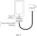
- FIG. 2 is a system connection diagram of a rapid charging system for a mobile terminal of the present disclosure.
- the charging accessory is connected to the cell phone through the Type-C interface, and the charging accessory is connected to the charger through the Type-C or micro USB interface.
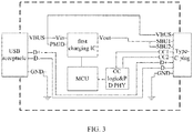
- FIG. 3 is a USB interface circuit diagram of a charging accessory in a rapid charging system for a mobile terminal of the present disclosure, where includes a USB receptacle, a first charging IC connected to the USB receptacle, a microcontroller MCU connected to the first charging IC, and a Type-C plug.
- the communication protocols between the microcontroller MCU and the first charging IC and the Type-C plug are the CC logic and PD protocol defined by the USB Type-C.
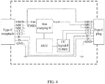
- FIG. 4 is a Type-C interface circuit diagram of a charging accessory in a rapid charging system for a mobile terminal of the present disclosure, where includes a Type-C receptacle, a first charging IC connected to the Type-C receptacle, a microcontroller MCU connected to the first charging IC, and a Type-C plug.
- the communication protocols between the microcontroller MCU and the first charging IC and the Type-C plug are the CC logic and PD protocol defined by the USB Type-C.
- FIG. 5 is a control circuit diagram of a mobile terminal in a rapid charging system for a mobile terminal of the present disclosure, where includes a Type-C receptacle, a second charging IC connected to the Type-C receptacle, a load switch connected to the Type-C receptacle, a controller AP connected to the second charging IC and the load switch, and a battery.
- An operation principle of the rapid charging system for the mobile terminal of the present disclosure is as follows.
- the controller of the mobile terminal communicates with the charging accessory through the Type-C interface, and the communication protocols are the CC logic and the PD protocol defined by the USB Type-C.
- the load switch is turned on by the controller AP.
- a first charging IC of the charging accessory is connected to the path of the battery. This path utilizes the reserved SBU pin of the Type-C interface.
- the microcontroller MCU controls the first charging IC to start charging, and the controller AP controls the second charging IC of the cell phone to start charging.
- the two ICs are charged together to increase current and dissipate heat.
- the second charging IC of the cell phone stops charging, and the first charging IC of the charging accessory charges until power of the battery is full.
- a temperature sensor can also be disposed on the charging accessory, and a first temperature of the cell phone can be obtained through the Type-C interface.
- the microcontroller MCU of the charging accessory can adjust charging currents of the cell phone and the charging accessory according to the first temperature of the cell phone and a second temperature of the charging accessory. If the first temperature of the cell phone is low (or the currents of the both are the same), the charging current of the second charging IC of the cell phone can be increased. If the first temperature of the cell phone is higher, the second charging IC of the cell phone stops charging, and only the first charging IC of the charging accessory charges.
- the first charging IC of the charging accessory stops charging, and only the second charging IC of the cell phone is charges, so as to reduce the first temperature of the cell phone, and balance the temperatures of the both to prevent the temperature from being too high and damaged.
- the charger can be connected to QC2.0 or PE+ rapid charger.
- the controller AP can still communicate with the charger through D+D-, and control the charger to increase an output voltage, such as 9V, 12V, to achieve the purpose of improving a power of the charger.
- the interface can be Type-C or micro USB interface.
- the charging accessory and the cell phone are directly connected through the Type-C interface, a cable is omitted in between, which saves cost and reduces cable impedance.
- the cell phone is equipped with a charging accessory, which is connected between the cell phone and the charger.
- the charging accessory adds a charging path to the cell phone, thereby increasing the charging current.
- the charging circuit is on the charging accessory, so that the heat is transferred from the cell phone to the charging accessory, thereby dispersing the heat and improving the heat dissipation efficiency.
Landscapes
- Engineering & Computer Science (AREA)
- Power Engineering (AREA)
- Manufacturing & Machinery (AREA)
- Chemical & Material Sciences (AREA)
- Chemical Kinetics & Catalysis (AREA)
- Electrochemistry (AREA)
- General Chemical & Material Sciences (AREA)
- Charge And Discharge Circuits For Batteries Or The Like (AREA)
Claims (11)
- Schnellladeverfahren für eine Batterie eines mobilen Endgeräts, umfassend:Anschließen (S10) eines Ladezubehörs zwischen einem mobilen Endgerät und einem Ladegerät;Kommunizieren (S11) einer Steuerung des mobilen Endgeräts über eine USB-Typ-C-Schnittstelle mit dem Ladezubehör, nachdem das mobile Endgerät erkannt hat, dass das Ladegerät an eine elektrische Leistungsversorgung angeschlossen ist;Einschalten (S12) eines Lastschalters des mobilen Endgeräts durch die Steuerung, nachdem von der Steuerung des mobilen Endgeräts ein erfolgreicher Handshake mit einer Mikrosteuerung des Ladezubehörs durchgeführt wurde, sodass ein erster Lade-IC des Ladezubehörs an einen Pfad der Batterie angeschlossen wird, die Mikrosteuerung den ersten Lade-IC steuert, um das Laden zu starten, und die Steuerung einen zweiten Lade-IC des mobilen Endgeräts steuert, um das Laden zu starten; undwenn ein Ladestrom auf eine Schwelle absinkt, wenn Leistung der Batterie ansteigt, Stoppen (S13) des Ladens durch den zweiten Lade-IC des mobilen Endgeräts, und Weiterladenlassen durch den ersten Lade-IC des Ladezubehörs, bis die Batterie volle Leistung hat, dadurch gekennzeichnet, dass im Ladezubehör ein Temperatursensor angeordnet ist, und eine erste Temperatur des mobilen Endgeräts über die USB-Typ-C-Schnittstelle erhalten wird, und die Mikrosteuerung des Ladezubehörs so ausgelegt ist, dass sie einen Ladestrom des mobilen Endgeräts und einen Ladestrom des Ladezubehörs je nach der ersten Temperatur des mobilen Endgeräts und einer zweiten Temperatur des Ladezubehörs anpasst.
- Schnellladeverfahren für die Batterie des mobilen Endgeräts nach Anspruch 1, dadurch gekennzeichnet, dass es sich bei Kommunikationsprotokollen der Steuerung des mobilen Endgeräts, die über die USB-Typ-C-Schnittstelle mit dem Ladezubehör kommuniziert, um ein CC-Logik und ein PD-Protokoll handelt, die durch einen USB-Typ C definiert sind.
- Schnellladeverfahren für das mobile Endgerät nach Anspruch 2, dadurch gekennzeichnet, dass der erste Lade-IC des Ladezubehörs über einen reservierten SBU-Pin der USB-Typ-C-Schnittstelle an den Pfad der Batterie angeschlossen wird.
- Schnellladeverfahren für die Batterie des mobilen Endgeräts nach Anspruch 2, dadurch gekennzeichnet, dass es sich beim mobilen Endgerät um ein Mobiltelefon handelt.
- Schnellladeverfahren für das mobile Endgerät nach Anspruch 1, dadurch gekennzeichnet, dass der Ladestrom des zweiten Lade-ICs des mobilen Endgeräts ansteigt, wenn die erste Temperatur des mobilen Endgeräts niedriger ist als eine erste vorbestimmte Temperatur.
- Schnellladeverfahren für die Batterie des mobilen Endgeräts nach Anspruch 1, dadurch gekennzeichnet, dass der zweite Lade-IC des mobilen Endgeräts das Laden stoppt und der erste Lade-IC des Ladezubehörs lädt, wenn die erste Temperatur des mobilen Endgeräts höher ist als eine zweite vorbestimmte Temperatur.
- Schnellladeverfahren für die Batterie des mobilen Endgeräts nach Anspruch 1, dadurch gekennzeichnet, dass der erste Lade-IC des Ladezubehörs das Laden stoppt und der zweite Lade-IC des mobilen Endgeräts lädt, wenn die zweite Temperatur des Ladezubehörs höher ist als eine zweite vorbestimmte Temperatur.
- Schnellladesystem für eine Batterie eines mobilen Endgeräts, umfassend: ein mobiles Endgerät, ein Ladegerät, und ein Ladezubehör, das zwischen dem mobilen Endgerät und dem Ladegerät angeschlossen wird,
wobei das mobile Endgerät eine Steuerschaltung des mobilen Endgeräts umfasst, die Steuerschaltung des mobilen Endgeräts einen zweiten Lade-IC des mobilen Endgeräts, eine Steuerung, und einen Lastschalter umfasst, der an den zweiten Lade-IC des mobilen Endgeräts und die Steuerung angeschlossen ist;
das Ladezubehör eine Ladezubehörschaltung umfasst, und die Ladezubehörschaltung einen ersten Lade-IC des Ladezubehörs und eine Mikrosteuerung umfasst, die an den ersten Lade-IC des Ladezubehörs angeschlossen ist;
die Steuerung des mobilen Endgeräts über eine USB-Typ-C-Schnittstelle mit dem Ladezubehör kommuniziert, wodurch das in Anspruch 1 definierte Verfahren ermöglicht wird; und
dadurch gekennzeichnet, dass im Ladezubehör ein Temperatursensor angeordnet ist, und über die Typ-C-Schnittstelle eine erste Temperatur des mobilen Endgeräts erhalten wird, und die Mikrosteuerung des Ladezubehörs so ausgelegt ist, dass sie einen Ladestrom des mobilen Endgeräts und einen Ladestrom des Ladezubehörs je nach der ersten Temperatur des mobilen Endgeräts und einer zweiten Temperatur des Ladezubehörs anpasst. - Schnellladesystem für die Batterie des mobilen Endgeräts nach Anspruch 8, dadurch gekennzeichnet, dass es sich bei Kommunikationsprotokollen der Steuerung des mobilen Endgeräts, die über die USB-Typ-C-Schnittstelle mit dem Ladezubehör kommuniziert, um eine CC-Logik und ein PD-Protokoll handelt, die durch einen USB-Typ C definiert sind.
- Schnellladesystem für das mobile Endgerät nach Anspruch 9, dadurch gekennzeichnet, dass der erste Lade-IC des Ladezubehörs über einen reservierten SBU-Pin der USB-Typ-C-Schnittstelle an den Pfad der Batterie angeschlossen wird.
- Schnellladesystem für das mobile Endgerät nach Anspruch 8, dadurch gekennzeichnet, dass es sich beim mobilen Endgerät um ein Mobiltelefon handelt.
Applications Claiming Priority (2)
| Application Number | Priority Date | Filing Date | Title |
|---|---|---|---|
| CN201610615620.5A CN106067573B (zh) | 2016-07-29 | 2016-07-29 | 移动终端快速充电方法及系统 |
| PCT/CN2017/085663 WO2018019021A1 (zh) | 2016-07-29 | 2017-05-24 | 移动终端快速充电方法及系统 |
Publications (3)
| Publication Number | Publication Date |
|---|---|
| EP3493322A1 EP3493322A1 (de) | 2019-06-05 |
| EP3493322A4 EP3493322A4 (de) | 2020-04-01 |
| EP3493322B1 true EP3493322B1 (de) | 2021-07-21 |
Family
ID=57207640
Family Applications (1)
| Application Number | Title | Priority Date | Filing Date |
|---|---|---|---|
| EP17833326.6A Active EP3493322B1 (de) | 2016-07-29 | 2017-05-24 | Schnellaufladeverfahren und -system für mobiles endgerät |
Country Status (4)
| Country | Link |
|---|---|
| US (1) | US11127991B2 (de) |
| EP (1) | EP3493322B1 (de) |
| CN (1) | CN106067573B (de) |
| WO (1) | WO2018019021A1 (de) |
Families Citing this family (11)
| Publication number | Priority date | Publication date | Assignee | Title |
|---|---|---|---|---|
| CN106067573B (zh) | 2016-07-29 | 2019-02-26 | 惠州Tcl移动通信有限公司 | 移动终端快速充电方法及系统 |
| CN106786954B (zh) * | 2017-01-06 | 2019-05-14 | 深圳市新国都支付技术有限公司 | 一种充电适配器自适应调节充电时间装置、系统及方法 |
| CN107342602B (zh) * | 2017-03-30 | 2019-02-05 | 吴钰淳 | 适配器、电子设备快充装置及快充方法 |
| CN107994627B (zh) * | 2017-09-28 | 2020-10-23 | 珠海智融科技有限公司 | 一种基于TypeC协议和PD协议的移动电源控制装置 |
| CN108710593B (zh) * | 2018-05-24 | 2021-10-15 | 环旭电子股份有限公司 | 一种基于Type-C连接器的供电方法及装置 |
| CN110881698B (zh) * | 2018-08-21 | 2022-07-12 | 湖南中烟工业有限责任公司 | 一种分体式低温烟具充电检测控制方法 |
| TW202020676A (zh) | 2018-11-26 | 2020-06-01 | 和碩聯合科技股份有限公司 | 具有通用序列匯流排c型連接器的電子裝置 |
| CN111447782B (zh) * | 2019-01-17 | 2022-01-18 | Oppo广东移动通信有限公司 | 充电系统、散热装置及其控制方法 |
| CN110944076B (zh) * | 2019-12-30 | 2025-01-14 | 上海爻火微电子有限公司 | 电子设备与兼具快充与音频传输功能的配件 |
| CN112886688B (zh) * | 2021-04-12 | 2023-02-10 | 浦江绣龙智能科技有限公司 | 一种TypeC接口电路及TypeC接口设备 |
| CN120767956A (zh) * | 2024-06-21 | 2025-10-10 | 荣耀终端股份有限公司 | 电子设备及充电方法 |
Family Cites Families (16)
| Publication number | Priority date | Publication date | Assignee | Title |
|---|---|---|---|---|
| KR100782271B1 (ko) * | 2005-11-28 | 2007-12-04 | 엘지전자 주식회사 | 휴대 단말기의 충전 제어 장치 및 방법 |
| CN102222945A (zh) | 2010-04-19 | 2011-10-19 | 罗恩荣 | 通信电源降压节能方法 |
| TWM402554U (en) | 2010-11-10 | 2011-04-21 | Richtek Technology Corp | Charger circuit |
| US9379558B2 (en) | 2011-03-08 | 2016-06-28 | Lenovo (Singapore) Pte. Ltd. | Dual rate charger for notebook computer |
| JP5644650B2 (ja) * | 2011-04-18 | 2014-12-24 | 三菱電機株式会社 | 電気自動車と家屋間の充放電システム及び充放電装置 |
| US9071067B2 (en) * | 2011-05-12 | 2015-06-30 | Lenovo (Singapore) Pte. Ltd. | Fast battery charging system and method |
| CN102593930B (zh) * | 2012-02-28 | 2015-01-21 | 惠州Tcl移动通信有限公司 | 一种移动终端的充电系统 |
| CN202737499U (zh) | 2012-06-20 | 2013-02-13 | 北京壹人壹本信息科技有限公司 | 便携式电子设备 |
| CN203086213U (zh) * | 2013-02-06 | 2013-07-24 | 深圳市金泰克半导体有限公司 | 一种快速充电器及带有该充电器的移动电源 |
| KR20150000020A (ko) * | 2013-06-19 | 2015-01-02 | 삼성전자주식회사 | 충전 기기 및 그 동작 방법 |
| CN105247755A (zh) | 2013-12-26 | 2016-01-13 | 联发科技股份有限公司 | 多路径充电器及其充电方法 |
| CN106385094B (zh) * | 2014-01-28 | 2019-02-12 | Oppo广东移动通信有限公司 | 快速充电控制方法和系统 |
| CN104410116A (zh) * | 2014-11-18 | 2015-03-11 | 深圳市中兴移动通信有限公司 | 快速充电装置和快速充电方法 |
| CN105207289B9 (zh) * | 2015-09-14 | 2018-07-24 | 联想(北京)有限公司 | 一种充电模组、电子设备和充电方法 |
| CN105656115B (zh) | 2015-11-30 | 2019-05-14 | 东莞酷派软件技术有限公司 | 一种双通道充电方法、系统和终端 |
| CN106067573B (zh) | 2016-07-29 | 2019-02-26 | 惠州Tcl移动通信有限公司 | 移动终端快速充电方法及系统 |
-
2016
- 2016-07-29 CN CN201610615620.5A patent/CN106067573B/zh active Active
-
2017
- 2017-05-24 EP EP17833326.6A patent/EP3493322B1/de active Active
- 2017-05-24 US US16/321,049 patent/US11127991B2/en active Active
- 2017-05-24 WO PCT/CN2017/085663 patent/WO2018019021A1/zh not_active Ceased
Also Published As
| Publication number | Publication date |
|---|---|
| EP3493322A1 (de) | 2019-06-05 |
| EP3493322A4 (de) | 2020-04-01 |
| WO2018019021A1 (zh) | 2018-02-01 |
| US20190173137A1 (en) | 2019-06-06 |
| CN106067573A (zh) | 2016-11-02 |
| US11127991B2 (en) | 2021-09-21 |
| CN106067573B (zh) | 2019-02-26 |
Similar Documents
| Publication | Publication Date | Title |
|---|---|---|
| EP3493322B1 (de) | Schnellaufladeverfahren und -system für mobiles endgerät | |
| CN105553001B (zh) | 充电方法和智能终端 | |
| CN103107584B (zh) | 一种具有无线移动充电功能的装置及其无线充电方法 | |
| US11133701B2 (en) | Method and apparatus for charging and mutual charging a combination of intelligent devices | |
| CN115053201B (zh) | 智能手机和附加设备供电系统 | |
| CN102593930B (zh) | 一种移动终端的充电系统 | |
| CN105656162A (zh) | 基于usb pd协议的快速充电系统及方法 | |
| CN105426332B (zh) | 通讯接口电路、便携式电子设备及电子系统 | |
| CN103580255A (zh) | 一种快速充电终端 | |
| CN206547012U (zh) | 充电电路及电子设备 | |
| WO2025232283A1 (zh) | 一种充电装置 | |
| EP4224668A1 (de) | Drahtloses ladegerät und drahtloses ladesystem für wearable-vorrichtung | |
| CN107248758B (zh) | 一种智能型双通道快充放电路径管理系统及方法 | |
| CN217307292U (zh) | 自动断电tws蓝牙耳机充电系统 | |
| CN106786978A (zh) | 一种充电系统及移动终端 | |
| WO2023005663A1 (zh) | 耳机兼容电路、耳机充电装置及耳机设备 | |
| CN110380469A (zh) | 电子设备和供电方法 | |
| CN105790373A (zh) | 一种电源装置及电子设备 | |
| CN105490355A (zh) | 移动终端与充电器 | |
| CN106300466A (zh) | 一种otg快速充电的方法、装置及终端 | |
| CN107204636A (zh) | 在充电过程中检测电池电压以调整供电电流的充电方法 | |
| CN206452163U (zh) | 充电装置 | |
| CN106972571B (zh) | 大规模终端智能充电系统及其方法 | |
| CN206237153U (zh) | 一种充电管理系统 | |
| US12506363B2 (en) | Electronic device |
Legal Events
| Date | Code | Title | Description |
|---|---|---|---|
| STAA | Information on the status of an ep patent application or granted ep patent |
Free format text: STATUS: THE INTERNATIONAL PUBLICATION HAS BEEN MADE |
|
| PUAI | Public reference made under article 153(3) epc to a published international application that has entered the european phase |
Free format text: ORIGINAL CODE: 0009012 |
|
| STAA | Information on the status of an ep patent application or granted ep patent |
Free format text: STATUS: REQUEST FOR EXAMINATION WAS MADE |
|
| 17P | Request for examination filed |
Effective date: 20181211 |
|
| AK | Designated contracting states |
Kind code of ref document: A1 Designated state(s): AL AT BE BG CH CY CZ DE DK EE ES FI FR GB GR HR HU IE IS IT LI LT LU LV MC MK MT NL NO PL PT RO RS SE SI SK SM TR |
|
| AX | Request for extension of the european patent |
Extension state: BA ME |
|
| DAV | Request for validation of the european patent (deleted) | ||
| DAX | Request for extension of the european patent (deleted) | ||
| A4 | Supplementary search report drawn up and despatched |
Effective date: 20200228 |
|
| RIC1 | Information provided on ipc code assigned before grant |
Ipc: H02J 7/00 20060101ALI20200224BHEP Ipc: H01M 10/44 20060101AFI20200224BHEP |
|
| GRAP | Despatch of communication of intention to grant a patent |
Free format text: ORIGINAL CODE: EPIDOSNIGR1 |
|
| STAA | Information on the status of an ep patent application or granted ep patent |
Free format text: STATUS: GRANT OF PATENT IS INTENDED |
|
| INTG | Intention to grant announced |
Effective date: 20210409 |
|
| GRAS | Grant fee paid |
Free format text: ORIGINAL CODE: EPIDOSNIGR3 |
|
| GRAA | (expected) grant |
Free format text: ORIGINAL CODE: 0009210 |
|
| STAA | Information on the status of an ep patent application or granted ep patent |
Free format text: STATUS: THE PATENT HAS BEEN GRANTED |
|
| AK | Designated contracting states |
Kind code of ref document: B1 Designated state(s): AL AT BE BG CH CY CZ DE DK EE ES FI FR GB GR HR HU IE IS IT LI LT LU LV MC MK MT NL NO PL PT RO RS SE SI SK SM TR |
|
| REG | Reference to a national code |
Ref country code: GB Ref legal event code: FG4D |
|
| REG | Reference to a national code |
Ref country code: CH Ref legal event code: EP |
|
| REG | Reference to a national code |
Ref country code: DE Ref legal event code: R096 Ref document number: 602017042640 Country of ref document: DE |
|
| REG | Reference to a national code |
Ref country code: AT Ref legal event code: REF Ref document number: 1413438 Country of ref document: AT Kind code of ref document: T Effective date: 20210815 |
|
| REG | Reference to a national code |
Ref country code: IE Ref legal event code: FG4D |
|
| REG | Reference to a national code |
Ref country code: LT Ref legal event code: MG9D |
|
| REG | Reference to a national code |
Ref country code: NL Ref legal event code: MP Effective date: 20210721 |
|
| REG | Reference to a national code |
Ref country code: AT Ref legal event code: MK05 Ref document number: 1413438 Country of ref document: AT Kind code of ref document: T Effective date: 20210721 |
|
| PG25 | Lapsed in a contracting state [announced via postgrant information from national office to epo] |
Ref country code: PT Free format text: LAPSE BECAUSE OF FAILURE TO SUBMIT A TRANSLATION OF THE DESCRIPTION OR TO PAY THE FEE WITHIN THE PRESCRIBED TIME-LIMIT Effective date: 20211122 Ref country code: NL Free format text: LAPSE BECAUSE OF FAILURE TO SUBMIT A TRANSLATION OF THE DESCRIPTION OR TO PAY THE FEE WITHIN THE PRESCRIBED TIME-LIMIT Effective date: 20210721 Ref country code: NO Free format text: LAPSE BECAUSE OF FAILURE TO SUBMIT A TRANSLATION OF THE DESCRIPTION OR TO PAY THE FEE WITHIN THE PRESCRIBED TIME-LIMIT Effective date: 20211021 Ref country code: BG Free format text: LAPSE BECAUSE OF FAILURE TO SUBMIT A TRANSLATION OF THE DESCRIPTION OR TO PAY THE FEE WITHIN THE PRESCRIBED TIME-LIMIT Effective date: 20211021 Ref country code: AT Free format text: LAPSE BECAUSE OF FAILURE TO SUBMIT A TRANSLATION OF THE DESCRIPTION OR TO PAY THE FEE WITHIN THE PRESCRIBED TIME-LIMIT Effective date: 20210721 Ref country code: LT Free format text: LAPSE BECAUSE OF FAILURE TO SUBMIT A TRANSLATION OF THE DESCRIPTION OR TO PAY THE FEE WITHIN THE PRESCRIBED TIME-LIMIT Effective date: 20210721 Ref country code: RS Free format text: LAPSE BECAUSE OF FAILURE TO SUBMIT A TRANSLATION OF THE DESCRIPTION OR TO PAY THE FEE WITHIN THE PRESCRIBED TIME-LIMIT Effective date: 20210721 Ref country code: SE Free format text: LAPSE BECAUSE OF FAILURE TO SUBMIT A TRANSLATION OF THE DESCRIPTION OR TO PAY THE FEE WITHIN THE PRESCRIBED TIME-LIMIT Effective date: 20210721 Ref country code: HR Free format text: LAPSE BECAUSE OF FAILURE TO SUBMIT A TRANSLATION OF THE DESCRIPTION OR TO PAY THE FEE WITHIN THE PRESCRIBED TIME-LIMIT Effective date: 20210721 Ref country code: ES Free format text: LAPSE BECAUSE OF FAILURE TO SUBMIT A TRANSLATION OF THE DESCRIPTION OR TO PAY THE FEE WITHIN THE PRESCRIBED TIME-LIMIT Effective date: 20210721 Ref country code: FI Free format text: LAPSE BECAUSE OF FAILURE TO SUBMIT A TRANSLATION OF THE DESCRIPTION OR TO PAY THE FEE WITHIN THE PRESCRIBED TIME-LIMIT Effective date: 20210721 |
|
| PG25 | Lapsed in a contracting state [announced via postgrant information from national office to epo] |
Ref country code: PL Free format text: LAPSE BECAUSE OF FAILURE TO SUBMIT A TRANSLATION OF THE DESCRIPTION OR TO PAY THE FEE WITHIN THE PRESCRIBED TIME-LIMIT Effective date: 20210721 Ref country code: LV Free format text: LAPSE BECAUSE OF FAILURE TO SUBMIT A TRANSLATION OF THE DESCRIPTION OR TO PAY THE FEE WITHIN THE PRESCRIBED TIME-LIMIT Effective date: 20210721 Ref country code: GR Free format text: LAPSE BECAUSE OF FAILURE TO SUBMIT A TRANSLATION OF THE DESCRIPTION OR TO PAY THE FEE WITHIN THE PRESCRIBED TIME-LIMIT Effective date: 20211022 |
|
| REG | Reference to a national code |
Ref country code: DE Ref legal event code: R097 Ref document number: 602017042640 Country of ref document: DE |
|
| PG25 | Lapsed in a contracting state [announced via postgrant information from national office to epo] |
Ref country code: DK Free format text: LAPSE BECAUSE OF FAILURE TO SUBMIT A TRANSLATION OF THE DESCRIPTION OR TO PAY THE FEE WITHIN THE PRESCRIBED TIME-LIMIT Effective date: 20210721 |
|
| PLBE | No opposition filed within time limit |
Free format text: ORIGINAL CODE: 0009261 |
|
| STAA | Information on the status of an ep patent application or granted ep patent |
Free format text: STATUS: NO OPPOSITION FILED WITHIN TIME LIMIT |
|
| PG25 | Lapsed in a contracting state [announced via postgrant information from national office to epo] |
Ref country code: SM Free format text: LAPSE BECAUSE OF FAILURE TO SUBMIT A TRANSLATION OF THE DESCRIPTION OR TO PAY THE FEE WITHIN THE PRESCRIBED TIME-LIMIT Effective date: 20210721 Ref country code: SK Free format text: LAPSE BECAUSE OF FAILURE TO SUBMIT A TRANSLATION OF THE DESCRIPTION OR TO PAY THE FEE WITHIN THE PRESCRIBED TIME-LIMIT Effective date: 20210721 Ref country code: RO Free format text: LAPSE BECAUSE OF FAILURE TO SUBMIT A TRANSLATION OF THE DESCRIPTION OR TO PAY THE FEE WITHIN THE PRESCRIBED TIME-LIMIT Effective date: 20210721 Ref country code: EE Free format text: LAPSE BECAUSE OF FAILURE TO SUBMIT A TRANSLATION OF THE DESCRIPTION OR TO PAY THE FEE WITHIN THE PRESCRIBED TIME-LIMIT Effective date: 20210721 Ref country code: CZ Free format text: LAPSE BECAUSE OF FAILURE TO SUBMIT A TRANSLATION OF THE DESCRIPTION OR TO PAY THE FEE WITHIN THE PRESCRIBED TIME-LIMIT Effective date: 20210721 Ref country code: AL Free format text: LAPSE BECAUSE OF FAILURE TO SUBMIT A TRANSLATION OF THE DESCRIPTION OR TO PAY THE FEE WITHIN THE PRESCRIBED TIME-LIMIT Effective date: 20210721 |
|
| 26N | No opposition filed |
Effective date: 20220422 |
|
| PG25 | Lapsed in a contracting state [announced via postgrant information from national office to epo] |
Ref country code: IT Free format text: LAPSE BECAUSE OF FAILURE TO SUBMIT A TRANSLATION OF THE DESCRIPTION OR TO PAY THE FEE WITHIN THE PRESCRIBED TIME-LIMIT Effective date: 20210721 |
|
| REG | Reference to a national code |
Ref country code: CH Ref legal event code: PL |
|
| REG | Reference to a national code |
Ref country code: BE Ref legal event code: MM Effective date: 20220531 |
|
| PG25 | Lapsed in a contracting state [announced via postgrant information from national office to epo] |
Ref country code: MC Free format text: LAPSE BECAUSE OF FAILURE TO SUBMIT A TRANSLATION OF THE DESCRIPTION OR TO PAY THE FEE WITHIN THE PRESCRIBED TIME-LIMIT Effective date: 20210721 Ref country code: LU Free format text: LAPSE BECAUSE OF NON-PAYMENT OF DUE FEES Effective date: 20220524 Ref country code: LI Free format text: LAPSE BECAUSE OF NON-PAYMENT OF DUE FEES Effective date: 20220531 Ref country code: CH Free format text: LAPSE BECAUSE OF NON-PAYMENT OF DUE FEES Effective date: 20220531 |
|
| PG25 | Lapsed in a contracting state [announced via postgrant information from national office to epo] |
Ref country code: IE Free format text: LAPSE BECAUSE OF NON-PAYMENT OF DUE FEES Effective date: 20220524 |
|
| PG25 | Lapsed in a contracting state [announced via postgrant information from national office to epo] |
Ref country code: BE Free format text: LAPSE BECAUSE OF NON-PAYMENT OF DUE FEES Effective date: 20220531 |
|
| P01 | Opt-out of the competence of the unified patent court (upc) registered |
Effective date: 20230530 |
|
| PG25 | Lapsed in a contracting state [announced via postgrant information from national office to epo] |
Ref country code: HU Free format text: LAPSE BECAUSE OF FAILURE TO SUBMIT A TRANSLATION OF THE DESCRIPTION OR TO PAY THE FEE WITHIN THE PRESCRIBED TIME-LIMIT; INVALID AB INITIO Effective date: 20170524 |
|
| PG25 | Lapsed in a contracting state [announced via postgrant information from national office to epo] |
Ref country code: MK Free format text: LAPSE BECAUSE OF FAILURE TO SUBMIT A TRANSLATION OF THE DESCRIPTION OR TO PAY THE FEE WITHIN THE PRESCRIBED TIME-LIMIT Effective date: 20210721 Ref country code: CY Free format text: LAPSE BECAUSE OF FAILURE TO SUBMIT A TRANSLATION OF THE DESCRIPTION OR TO PAY THE FEE WITHIN THE PRESCRIBED TIME-LIMIT Effective date: 20210721 |
|
| PG25 | Lapsed in a contracting state [announced via postgrant information from national office to epo] |
Ref country code: TR Free format text: LAPSE BECAUSE OF FAILURE TO SUBMIT A TRANSLATION OF THE DESCRIPTION OR TO PAY THE FEE WITHIN THE PRESCRIBED TIME-LIMIT Effective date: 20210721 |
|
| PG25 | Lapsed in a contracting state [announced via postgrant information from national office to epo] |
Ref country code: MT Free format text: LAPSE BECAUSE OF FAILURE TO SUBMIT A TRANSLATION OF THE DESCRIPTION OR TO PAY THE FEE WITHIN THE PRESCRIBED TIME-LIMIT Effective date: 20210721 |
|
| PGFP | Annual fee paid to national office [announced via postgrant information from national office to epo] |
Ref country code: DE Payment date: 20250521 Year of fee payment: 9 |
|
| PGFP | Annual fee paid to national office [announced via postgrant information from national office to epo] |
Ref country code: FR Payment date: 20250528 Year of fee payment: 9 |
|
| PGFP | Annual fee paid to national office [announced via postgrant information from national office to epo] |
Ref country code: GB Payment date: 20260306 Year of fee payment: 10 |