EP3493321A1 - Method and system for determining discharging process of batterytechnical field - Google Patents
Method and system for determining discharging process of batterytechnical field Download PDFInfo
- Publication number
- EP3493321A1 EP3493321A1 EP17210300.4A EP17210300A EP3493321A1 EP 3493321 A1 EP3493321 A1 EP 3493321A1 EP 17210300 A EP17210300 A EP 17210300A EP 3493321 A1 EP3493321 A1 EP 3493321A1
- Authority
- EP
- European Patent Office
- Prior art keywords
- battery
- discharging
- characteristic
- charging
- aligned
- Prior art date
- Legal status (The legal status is an assumption and is not a legal conclusion. Google has not performed a legal analysis and makes no representation as to the accuracy of the status listed.)
- Granted
Links
Images








Classifications
-
- G—PHYSICS
- G01—MEASURING; TESTING
- G01R—MEASURING ELECTRIC VARIABLES; MEASURING MAGNETIC VARIABLES
- G01R31/00—Arrangements for testing electric properties; Arrangements for locating electric faults; Arrangements for electrical testing characterised by what is being tested not provided for elsewhere
- G01R31/36—Arrangements for testing, measuring or monitoring the electrical condition of accumulators or electric batteries, e.g. capacity or state of charge [SoC]
- G01R31/3644—Constructional arrangements
- G01R31/3646—Constructional arrangements for indicating electrical conditions or variables, e.g. visual or audible indicators
-
- B—PERFORMING OPERATIONS; TRANSPORTING
- B60—VEHICLES IN GENERAL
- B60L—PROPULSION OF ELECTRICALLY-PROPELLED VEHICLES; SUPPLYING ELECTRIC POWER FOR AUXILIARY EQUIPMENT OF ELECTRICALLY-PROPELLED VEHICLES; ELECTRODYNAMIC BRAKE SYSTEMS FOR VEHICLES IN GENERAL; MAGNETIC SUSPENSION OR LEVITATION FOR VEHICLES; MONITORING OPERATING VARIABLES OF ELECTRICALLY-PROPELLED VEHICLES; ELECTRIC SAFETY DEVICES FOR ELECTRICALLY-PROPELLED VEHICLES
- B60L50/00—Electric propulsion with power supplied within the vehicle
- B60L50/50—Electric propulsion with power supplied within the vehicle using propulsion power supplied by batteries or fuel cells
- B60L50/60—Electric propulsion with power supplied within the vehicle using propulsion power supplied by batteries or fuel cells using power supplied by batteries
- B60L50/64—Constructional details of batteries specially adapted for electric vehicles
-
- B—PERFORMING OPERATIONS; TRANSPORTING
- B60—VEHICLES IN GENERAL
- B60L—PROPULSION OF ELECTRICALLY-PROPELLED VEHICLES; SUPPLYING ELECTRIC POWER FOR AUXILIARY EQUIPMENT OF ELECTRICALLY-PROPELLED VEHICLES; ELECTRODYNAMIC BRAKE SYSTEMS FOR VEHICLES IN GENERAL; MAGNETIC SUSPENSION OR LEVITATION FOR VEHICLES; MONITORING OPERATING VARIABLES OF ELECTRICALLY-PROPELLED VEHICLES; ELECTRIC SAFETY DEVICES FOR ELECTRICALLY-PROPELLED VEHICLES
- B60L50/00—Electric propulsion with power supplied within the vehicle
- B60L50/50—Electric propulsion with power supplied within the vehicle using propulsion power supplied by batteries or fuel cells
- B60L50/60—Electric propulsion with power supplied within the vehicle using propulsion power supplied by batteries or fuel cells using power supplied by batteries
- B60L50/66—Arrangements of batteries
-
- B—PERFORMING OPERATIONS; TRANSPORTING
- B60—VEHICLES IN GENERAL
- B60L—PROPULSION OF ELECTRICALLY-PROPELLED VEHICLES; SUPPLYING ELECTRIC POWER FOR AUXILIARY EQUIPMENT OF ELECTRICALLY-PROPELLED VEHICLES; ELECTRODYNAMIC BRAKE SYSTEMS FOR VEHICLES IN GENERAL; MAGNETIC SUSPENSION OR LEVITATION FOR VEHICLES; MONITORING OPERATING VARIABLES OF ELECTRICALLY-PROPELLED VEHICLES; ELECTRIC SAFETY DEVICES FOR ELECTRICALLY-PROPELLED VEHICLES
- B60L53/00—Methods of charging batteries, specially adapted for electric vehicles; Charging stations or on-board charging equipment therefor; Exchange of energy storage elements in electric vehicles
- B60L53/30—Constructional details of charging stations
- B60L53/35—Means for automatic or assisted adjustment of the relative position of charging devices and vehicles
-
- B—PERFORMING OPERATIONS; TRANSPORTING
- B60—VEHICLES IN GENERAL
- B60L—PROPULSION OF ELECTRICALLY-PROPELLED VEHICLES; SUPPLYING ELECTRIC POWER FOR AUXILIARY EQUIPMENT OF ELECTRICALLY-PROPELLED VEHICLES; ELECTRODYNAMIC BRAKE SYSTEMS FOR VEHICLES IN GENERAL; MAGNETIC SUSPENSION OR LEVITATION FOR VEHICLES; MONITORING OPERATING VARIABLES OF ELECTRICALLY-PROPELLED VEHICLES; ELECTRIC SAFETY DEVICES FOR ELECTRICALLY-PROPELLED VEHICLES
- B60L53/00—Methods of charging batteries, specially adapted for electric vehicles; Charging stations or on-board charging equipment therefor; Exchange of energy storage elements in electric vehicles
- B60L53/60—Monitoring or controlling charging stations
-
- G—PHYSICS
- G01—MEASURING; TESTING
- G01R—MEASURING ELECTRIC VARIABLES; MEASURING MAGNETIC VARIABLES
- G01R31/00—Arrangements for testing electric properties; Arrangements for locating electric faults; Arrangements for electrical testing characterised by what is being tested not provided for elsewhere
- G01R31/36—Arrangements for testing, measuring or monitoring the electrical condition of accumulators or electric batteries, e.g. capacity or state of charge [SoC]
- G01R31/3644—Constructional arrangements
- G01R31/3648—Constructional arrangements comprising digital calculation means, e.g. for performing an algorithm
-
- G—PHYSICS
- G01—MEASURING; TESTING
- G01R—MEASURING ELECTRIC VARIABLES; MEASURING MAGNETIC VARIABLES
- G01R31/00—Arrangements for testing electric properties; Arrangements for locating electric faults; Arrangements for electrical testing characterised by what is being tested not provided for elsewhere
- G01R31/36—Arrangements for testing, measuring or monitoring the electrical condition of accumulators or electric batteries, e.g. capacity or state of charge [SoC]
- G01R31/382—Arrangements for monitoring battery or accumulator variables, e.g. SoC
-
- G—PHYSICS
- G01—MEASURING; TESTING
- G01R—MEASURING ELECTRIC VARIABLES; MEASURING MAGNETIC VARIABLES
- G01R31/00—Arrangements for testing electric properties; Arrangements for locating electric faults; Arrangements for electrical testing characterised by what is being tested not provided for elsewhere
- G01R31/36—Arrangements for testing, measuring or monitoring the electrical condition of accumulators or electric batteries, e.g. capacity or state of charge [SoC]
- G01R31/382—Arrangements for monitoring battery or accumulator variables, e.g. SoC
- G01R31/3828—Arrangements for monitoring battery or accumulator variables, e.g. SoC using current integration
- G01R31/3832—Arrangements for monitoring battery or accumulator variables, e.g. SoC using current integration without measurement of battery voltage
- G01R31/3833—Arrangements for monitoring battery or accumulator variables, e.g. SoC using current integration without measurement of battery voltage using analog integrators, e.g. coulomb-meters
-
- G—PHYSICS
- G01—MEASURING; TESTING
- G01R—MEASURING ELECTRIC VARIABLES; MEASURING MAGNETIC VARIABLES
- G01R31/00—Arrangements for testing electric properties; Arrangements for locating electric faults; Arrangements for electrical testing characterised by what is being tested not provided for elsewhere
- G01R31/36—Arrangements for testing, measuring or monitoring the electrical condition of accumulators or electric batteries, e.g. capacity or state of charge [SoC]
- G01R31/389—Measuring internal impedance, internal conductance or related variables
-
- G—PHYSICS
- G01—MEASURING; TESTING
- G01R—MEASURING ELECTRIC VARIABLES; MEASURING MAGNETIC VARIABLES
- G01R31/00—Arrangements for testing electric properties; Arrangements for locating electric faults; Arrangements for electrical testing characterised by what is being tested not provided for elsewhere
- G01R31/36—Arrangements for testing, measuring or monitoring the electrical condition of accumulators or electric batteries, e.g. capacity or state of charge [SoC]
- G01R31/392—Determining battery ageing or deterioration, e.g. state of health
-
- H—ELECTRICITY
- H01—ELECTRIC ELEMENTS
- H01M—PROCESSES OR MEANS, e.g. BATTERIES, FOR THE DIRECT CONVERSION OF CHEMICAL ENERGY INTO ELECTRICAL ENERGY
- H01M10/00—Secondary cells; Manufacture thereof
- H01M10/42—Methods or arrangements for servicing or maintenance of secondary cells or secondary half-cells
- H01M10/44—Methods for charging or discharging
-
- H—ELECTRICITY
- H01—ELECTRIC ELEMENTS
- H01M—PROCESSES OR MEANS, e.g. BATTERIES, FOR THE DIRECT CONVERSION OF CHEMICAL ENERGY INTO ELECTRICAL ENERGY
- H01M10/00—Secondary cells; Manufacture thereof
- H01M10/42—Methods or arrangements for servicing or maintenance of secondary cells or secondary half-cells
- H01M10/48—Accumulators combined with arrangements for measuring, testing or indicating the condition of cells, e.g. the level or density of the electrolyte
-
- H—ELECTRICITY
- H02—GENERATION; CONVERSION OR DISTRIBUTION OF ELECTRIC POWER
- H02J—ELECTRIC POWER NETWORKS; CIRCUIT ARRANGEMENTS OR SYSTEMS FOR SUPPLYING OR DISTRIBUTING ELECTRIC POWER; SYSTEMS FOR STORING ELECTRIC ENERGY
- H02J7/00—Circuit arrangements for charging or discharging batteries or for supplying loads from batteries
- H02J7/60—Circuit arrangements for charging or discharging batteries or for supplying loads from batteries including safety or protection arrangements
-
- H—ELECTRICITY
- H02—GENERATION; CONVERSION OR DISTRIBUTION OF ELECTRIC POWER
- H02J—ELECTRIC POWER NETWORKS; CIRCUIT ARRANGEMENTS OR SYSTEMS FOR SUPPLYING OR DISTRIBUTING ELECTRIC POWER; SYSTEMS FOR STORING ELECTRIC ENERGY
- H02J7/00—Circuit arrangements for charging or discharging batteries or for supplying loads from batteries
- H02J7/80—Circuit arrangements for charging or discharging batteries or for supplying loads from batteries including monitoring or indicating arrangements
-
- H—ELECTRICITY
- H02—GENERATION; CONVERSION OR DISTRIBUTION OF ELECTRIC POWER
- H02J—ELECTRIC POWER NETWORKS; CIRCUIT ARRANGEMENTS OR SYSTEMS FOR SUPPLYING OR DISTRIBUTING ELECTRIC POWER; SYSTEMS FOR STORING ELECTRIC ENERGY
- H02J7/00—Circuit arrangements for charging or discharging batteries or for supplying loads from batteries
- H02J7/90—Regulation of charging or discharging current or voltage
-
- H—ELECTRICITY
- H02—GENERATION; CONVERSION OR DISTRIBUTION OF ELECTRIC POWER
- H02J—ELECTRIC POWER NETWORKS; CIRCUIT ARRANGEMENTS OR SYSTEMS FOR SUPPLYING OR DISTRIBUTING ELECTRIC POWER; SYSTEMS FOR STORING ELECTRIC ENERGY
- H02J7/00—Circuit arrangements for charging or discharging batteries or for supplying loads from batteries
- H02J7/60—Circuit arrangements for charging or discharging batteries or for supplying loads from batteries including safety or protection arrangements
- H02J7/63—Circuit arrangements for charging or discharging batteries or for supplying loads from batteries including safety or protection arrangements against overdischarge
-
- H—ELECTRICITY
- H02—GENERATION; CONVERSION OR DISTRIBUTION OF ELECTRIC POWER
- H02J—ELECTRIC POWER NETWORKS; CIRCUIT ARRANGEMENTS OR SYSTEMS FOR SUPPLYING OR DISTRIBUTING ELECTRIC POWER; SYSTEMS FOR STORING ELECTRIC ENERGY
- H02J7/00—Circuit arrangements for charging or discharging batteries or for supplying loads from batteries
- H02J7/60—Circuit arrangements for charging or discharging batteries or for supplying loads from batteries including safety or protection arrangements
- H02J7/65—Circuit arrangements for charging or discharging batteries or for supplying loads from batteries including safety or protection arrangements against overtemperature
-
- Y—GENERAL TAGGING OF NEW TECHNOLOGICAL DEVELOPMENTS; GENERAL TAGGING OF CROSS-SECTIONAL TECHNOLOGIES SPANNING OVER SEVERAL SECTIONS OF THE IPC; TECHNICAL SUBJECTS COVERED BY FORMER USPC CROSS-REFERENCE ART COLLECTIONS [XRACs] AND DIGESTS
- Y02—TECHNOLOGIES OR APPLICATIONS FOR MITIGATION OR ADAPTATION AGAINST CLIMATE CHANGE
- Y02E—REDUCTION OF GREENHOUSE GAS [GHG] EMISSIONS, RELATED TO ENERGY GENERATION, TRANSMISSION OR DISTRIBUTION
- Y02E60/00—Enabling technologies; Technologies with a potential or indirect contribution to GHG emissions mitigation
- Y02E60/10—Energy storage using batteries
-
- Y—GENERAL TAGGING OF NEW TECHNOLOGICAL DEVELOPMENTS; GENERAL TAGGING OF CROSS-SECTIONAL TECHNOLOGIES SPANNING OVER SEVERAL SECTIONS OF THE IPC; TECHNICAL SUBJECTS COVERED BY FORMER USPC CROSS-REFERENCE ART COLLECTIONS [XRACs] AND DIGESTS
- Y02—TECHNOLOGIES OR APPLICATIONS FOR MITIGATION OR ADAPTATION AGAINST CLIMATE CHANGE
- Y02T—CLIMATE CHANGE MITIGATION TECHNOLOGIES RELATED TO TRANSPORTATION
- Y02T10/00—Road transport of goods or passengers
- Y02T10/60—Other road transportation technologies with climate change mitigation effect
- Y02T10/70—Energy storage systems for electromobility, e.g. batteries
-
- Y—GENERAL TAGGING OF NEW TECHNOLOGICAL DEVELOPMENTS; GENERAL TAGGING OF CROSS-SECTIONAL TECHNOLOGIES SPANNING OVER SEVERAL SECTIONS OF THE IPC; TECHNICAL SUBJECTS COVERED BY FORMER USPC CROSS-REFERENCE ART COLLECTIONS [XRACs] AND DIGESTS
- Y02—TECHNOLOGIES OR APPLICATIONS FOR MITIGATION OR ADAPTATION AGAINST CLIMATE CHANGE
- Y02T—CLIMATE CHANGE MITIGATION TECHNOLOGIES RELATED TO TRANSPORTATION
- Y02T10/00—Road transport of goods or passengers
- Y02T10/60—Other road transportation technologies with climate change mitigation effect
- Y02T10/7072—Electromobility specific charging systems or methods for batteries, ultracapacitors, supercapacitors or double-layer capacitors
-
- Y—GENERAL TAGGING OF NEW TECHNOLOGICAL DEVELOPMENTS; GENERAL TAGGING OF CROSS-SECTIONAL TECHNOLOGIES SPANNING OVER SEVERAL SECTIONS OF THE IPC; TECHNICAL SUBJECTS COVERED BY FORMER USPC CROSS-REFERENCE ART COLLECTIONS [XRACs] AND DIGESTS
- Y02—TECHNOLOGIES OR APPLICATIONS FOR MITIGATION OR ADAPTATION AGAINST CLIMATE CHANGE
- Y02T—CLIMATE CHANGE MITIGATION TECHNOLOGIES RELATED TO TRANSPORTATION
- Y02T90/00—Enabling technologies or technologies with a potential or indirect contribution to GHG emissions mitigation
- Y02T90/10—Technologies relating to charging of electric vehicles
- Y02T90/12—Electric charging stations
Definitions
- the disclosure is directed to a method and a system for determining a discharging process of a battery.
- a method for determining a discharging process of a battery includes steps of: measuring charging/discharging information of a battery; calculating a charging/discharging characteristic of the battery according to the charging/discharging information; aligning the charging/discharging characteristic of the battery according to a comparison characteristic point of a comparison characteristic to obtain an aligned charging/discharging characteristic; determining whether the battery is normal according to the aligned charging/discharging characteristic or a coulombic efficiency of the battery; calculating a safety probability of the battery according to the aligned charging/discharging characteristic and resistance of an internal short circuit of the battery when the battery is determined as being abnormal; and determining a discharging process of the battery according to the safety probability of the battery.
- a system for determining a discharging process of a battery includes a battery set, a data acquisition (DAQ) module, a characteristic calculating module and a safety probability calculating module.
- the battery set includes a battery.
- the DAQ module is configured to measure charging/discharging information of the battery.
- the characteristic calculating module is configured to calculate a charging/discharging characteristic of the battery according to the charging/discharging information, align the charging/discharging characteristic according to a comparison characteristic point of a comparison characteristic to obtain an aligned charging/discharging characteristic, and determine whether the battery is normal according to the aligned charging/discharging characteristic or a coulombic efficiency of the battery.
- the safety probability calculating module is configured to calculate a safety probability of the battery according to the aligned charging/discharging characteristic and resistance of internal short circuit of the battery, and determine a discharging process of the battery according to the safety probability
- a method for determining a discharging process includes: determining that a battery is abnormal; determining a safety determination range according to a battery capacity versus resistance relationship or a differential capacity versus resistance relationship, and calculating a safety probability of the battery according to danger levels and a quantity of events in the safety determination range; and determining the discharging process of the battery according to the safety probability of the battery.
- the system 100 for detecting resistance of an internal circuit of a battery may be placed in a mobile device, e.g., a cell phone, a personal digital assistant (PDA), a tablet computer, a laptop computer, a point-of-sales (POS) machine, a portable media player, a digital camera or a wearable device.
- the system 100 for detecting resistance of an internal circuit of a battery may also be placed in a vehicle, e.g., an automobile, a motorcycle, an aircraft, a boat, a submarine, an unmanned automobile, a drone or an unmanned boat.
- the system 100 for detecting resistance of an internal circuit of a battery may also be placed in a toy or a model of any of the above vehicles.
- the battery set 102 is coupled to the charging circuit 104 and the DAQ module 106, and includes one or multiple batteries.
- the batteries of the battery set 102 are formed in a serial, parallel or array structure.
- the array structure may be the reconfigurable array of inexpensive batteries architecture (RAIBA) technique.
- the above batteries may be rechargeable batteries such as lithium-ion batteries, lithium metal batteries, lead-acid batteries, nickel-cadmium batteries, nickel-metal hydride batteries, or may be super capacitors, fuel cells or solar cells.
- the charging circuit 104 is coupled to the battery set 102, and may be a circuit or a switch.
- the charging circuit 104 is capable of charging or terminating the charging of the batteries in the battery set 102.
- the charging circuit 104 may be provided outside the system 100 for detecting resistance of an internal short circuit of a battery.
- the DAQ module 106 is coupled to the battery set 102 and the characteristic calculating module 110.
- the DAQ module 106 may be one or multiple separate or integrated meters or sensors, e.g., a voltmeter, an ammeter, a temperature sensor and/or a time recorder.
- the DAQ module 106 may be a detection circuit.
- the DAQ module 106 may be an independent device or instrument outside the system 100 for detecting resistance of an internal short circuit of a battery.
- the DAQ module 106 may measure and/or record a voltage, a current, a temperature or a time of the batteries in the battery set by using the above meters, sensors, detection circuits, devices and/or instruments.
- the storage unit 108 is coupled to the characteristic calculating module 110.
- the storage unit 108 may be a hardware unit, e.g., a memory, a hard drive, a solid-state disk (SSD), a flash memory or a read-only memory (ROM).
- SSD solid-state disk
- ROM read-only memory
- the characteristic calculating module 110 is coupled to the DAQ module 106, the storage unit 108 and the internal short-circuit resistance calculating module 112.
- the characteristic calculating module 110 may be a hardware circuit, a software module executed by a processor (not shown) or a controller (not shown), or partly a circuit and partly a software module executed by a processor or a controller. Details of the function of the characteristic calculating module 110 are to be described shortly.
- the internal short-circuit resistance calculating module 112 is coupled to the characteristic calculating module 110.
- the internal short-circuit resistance calculating module 112 may be a hardware circuit, a software module executed by a processor (not shown) or a controller (not shown), or partly a circuit and partly a software module executed by a processor or a controller. Details of the function of the internal short-circuit resistance calculating module 112 are to be described shortly.
- the characteristic calculating module 110 and the internal short-circuit resistance calculating module 112 may be integrated into one module.
- the system 200 for determining a discharging process of a battery may be placed in a mobile device, e.g., a cell phone, a PDA, a tablet computer, a laptop computer, a POS machine, a portable media player, a digital camera, or a wearable device.
- the system 200 for determining a discharging process of a battery may also be placed in a vehicle, e.g., an automobile, a motorcycle, an aircraft, a boat, a submarine, an unmanned automobile, a drone or an unmanned boat.
- the system 200 for determining a discharging process of a battery may also be placed in a toy or a model of any of the above vehicles.
- the abnormal discharging circuit 116 is coupled to the battery set 102 and the safety probability calculating module 114.
- the abnormal discharging circuit 116 may include one or multiple variable resistors, one or multiple fixed resistors, or a combination of one or multiple variable resistors and/or one or multiple fixed resistors that are connected in series or in parallel.
- the abnormal discharging circuit 116 may include a circuit consisting of one or multiple active components or other passive components. Active components are, e.g., metal-oxide-semiconductor field-effect transistors (MOSFETs) or bipolar transistors, and passive components are, e.g., inductors or capacitors.
- MOSFETs metal-oxide-semiconductor field-effect transistors
- passive components are, e.g., inductors or capacitors.
- the system 300 for detecting resistance of an internal short circuit of a battery and determining a discharging process of a battery includes a battery set 102, a charging circuit 104, a DAQ module 106, a storage unit 108, a characteristic calculating module 110, an internal short-circuit resistance calculating module 112, a safety probability calculating module 114 and an abnormal discharging circuit 116.
- the system 300 for detecting resistance of an internal short circuit of a battery and determining a discharging process of a battery may be placed in a mobile device, e.g., a cell phone, a PDA, a tablet computer, a laptop computer, a POS machine, a portable media player, a digital camera, or a wearable device.
- the system 300 for detecting resistance of an internal short circuit of a battery and a discharging process of a battery may also be placed in a vehicle, e.g., an automobile, a motorcycle, an aircraft, a boat, a submarine, an unmanned automobile, a drone or an unmanned boat.
- the system 300 for detecting resistance of an internal short circuit of a battery and a discharging process of a battery may also be placed in a toy or a model of any of the above vehicles.
- the battery set 102, the charging circuit 104, the DAQ module 106, the storage unit 108, the characteristic calculating module 110 and the internal short-circuit resistance calculating module 112 in FIG. 1C are identical or similar to the charging circuit 104, the DAQ module 106, the storage unit 108, the characteristic calculating module 110 and the internal short-circuit resistance calculating module 112 in FIG. 1A , and associated details can be referred from the corresponding description.
- the characteristic calculating module 110 is coupled to the DAQ module 106, the storage unit 108, the internal short-circuit resistance calculating module 112 and the safety probability calculating module 114.
- the internal short-circuit resistance calculating module 112 is coupled to the characteristic calculating module 110 and the safety probability calculating module 114.
- the safety probability calculating module 114 is coupled to the characteristic calculating module 110, the internal short-circuit resistance calculating module 112 and the abnormal discharging circuit 116.
- the characteristic calculating module 110, the internal short-circuit resistance calculating module 112 and the safety probability calculating module 114 may be integrated into one module.
- the resistance of the variable resistor 1162 may be adjusted to a minimum value (or a predetermined small resistance value) so as to accelerate the speed of discharging the battery 1021.
- the resistance of the variable resistor 1162 may be adjusted to a maximum value (or a predetermined large resistance value) or is disconnected from the battery of the battery set 102, so as to prevent or reduce the discharging of the battery set 102 via the variable resistor 1162.
- the resistance of the variable resistor 1162 may be adjusted to a maximum value (or a predetermined large resistance value) or be disconnected from the battery of the battery set 102, so as to prevent or reduce the discharging of the battery set 102 via the variable resistor 1162.
- the sets of voltage data, current data, time data and/or battery temperature data have a corresponding relationship. For example, corresponding to the time data t i , the voltage data is V i , the current data is I i and/or the battery temperature data is T i .
- the charging/discharging information includes charging information during a charging process of the battery 1021 or discharging information during a discharging process of the battery 1021. In one embodiment, the charging/discharging information may be charging information during a charging process of the battery 1021, wherein the charging information includes charging voltage information, charging current information, charging time information and/or charging battery temperature information.
- the discharging process is, for example, discharging from a maximum voltage (e.g., 4.2 V) of the battery 1021 to a minimum voltage (e.g., 0 V) of the battery 1021.
- the discharging process is, for example, discharging from a predetermined high voltage of the battery 1021 to a predetermined low voltage of the battery 1021.
- the discharging process is, for example, discharging from a current voltage (e.g., a user plays games on a cell phone) of the battery 1021 to a minimum voltage, a predetermined lower voltage or a voltage when the discharging is terminated (e.g., a user finishes a game on a cell phone and turns off the cell phone).
- the characteristic calculating module 110 further draws a battery capacity versus voltage (Q-V) relationship curve to obtain a battery capacity versus voltage (Q-V) relationship, differentiates the battery capacity information with respect to the voltage information to obtain differential capacity information, and draws a differential capacity (dQ/dV) versus voltage (dQ/dV-V) relationship curve to obtain a differential capacity versus voltage (dQ/dV-V) relationship.
- the charging/discharging characteristic is a charging characteristic during a charging process of the battery 1021, e.g., a Q-V relationship and/or a dQ/dV-V relationship during the charging process of the battery 1021.
- the characteristic calculating module 110 calculates charging battery capacity information according to charging current information and charging time information of the battery 1021, e.g., multiplying the charging current information by the charging time information to obtain the charging battery capacity information, and draws a relationship curve of the charging battery capacity versus the charging voltage by using the charging battery capacity as the vertical axis and the charging voltage information as the horizontal axis to obtain the Q-V relationship during the charging process.
- the charging voltage information includes a plurality of sets of charging voltage data
- the charging current information includes a plurality of sets of charging current data
- the charging time information includes a plurality of sets of charging time data.
- the calculated charging battery capacity information has a corresponding number of sets of charging battery capacity data.
- step S230 is performed.
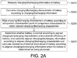
- the characteristic calculating module 110 is configured to align the charging/discharging characteristic of the battery 1021 according to a comparison characteristic point of a comparison characteristic to obtain an aligned charging/discharging characteristic.
- the characteristic calculating module 110 aligns the charging/discharging characteristic of the battery 1021 with a comparison characteristic point of a comparison characteristic to obtain an aligned charging/discharging characteristic.
- details of the alignment are as follows.
- the charging/discharging characteristic includes a relationship curve, which includes charging/discharging characteristic points.
- the relationship curve of the charging/discharging characteristic is shifted, such that the horizontal-axis coordinates and/or the vertical-axis coordinates of the charging/discharging characteristic points of the relationship curve of the charging/discharging characteristic are identical to the horizontal-axis coordinates and/or the vertical-axis coordinates of the comparison characteristic points of the comparison characteristic.
- the comparison characteristic is stored in the storage unit 108.
- the charging/discharging characteristic of the battery is a charging characteristic or a discharging characteristic of the battery 1021
- the comparison characteristic is a history charging characteristic of the battery 1021 or a history discharging characteristic of the battery 1021.
- the charging characteristic is stored as a history charging characteristic of the battery 1021.
- the discharging characteristic is stored as a history discharging characteristic of the battery 1021.
- the comparison characteristic is a history charging characteristic of another battery or a history discharging characteristic of another battery.
- the another battery is, for example, a battery of the same manufacturer brand or of the same model as the battery 1021.
- the charging/discharging characteristic of the battery 1021 is one of the charging characteristic and the discharging characteristic of the battery 1021, and the comparison characteristic is the other of the charging characteristic and the discharging characteristic of the battery 1021.
- a differential capacity (dQ/dV) versus voltage (dQ/dV-V) relationship during a discharging process is taken as the charging/discharging characteristic
- a differential capacity (dQ/dV) versus voltage (dQ/dV-V) relationship during a charging process is taken as the comparison characteristic as an example, to illustrate details of aligning the charging/discharging characteristic point of the charging/discharging characteristic of the battery 1021 with the comparison characteristic point of the comparison characteristic.
- the characteristic calculating module 110 identifies a local maximum point of the relationship curve of discharging differential capacity versus discharging voltage as a discharging local maximum point, identifies a local maximum point of a relationship curve of charging differential capacity versus charging voltage as a charging local maximum point, and shifts the relationship curve of discharging differential capacity versus discharging voltage such that the horizontal-axis coordinate of the discharging local maximum point is substantially identical to the horizontal-axis coordinate of the charging local maximum point, thus completing the alignment.
- the shifted relationship curve of discharging differential capacity versus discharging voltage is the aligned charging/discharging characteristic.
- the number of the charging/discharging characteristic point and/or the comparison characteristic point may be more than one.
- a charging/discharging characteristic point having a largest error from the corresponding comparison characteristic point may be omitted, or different weightings may be assigned to different charging/discharging characteristic points for the alignment.
- Step S240 is performed after step S230.
- the characteristic calculating module 110 is configured to determine whether the battery 1021 is normal according to the aligned charging/discharging characteristic or a coulombic efficiency of the battery 1021.
- the internal short-circuit resistance calculating module 112 is configured to calculate aligned charging/discharging information according to the aligned charging/discharging characteristic, and calculate the resistance of an internal short circuit of the battery 1021 according to the aligned charging/discharging information.
- the aligned charging/discharging information includes aligned voltage information, aligned current information, aligned battery capacity information and/or aligned time information.
- a discharging process of the battery 1021 may be determined according to the calculated resistance of the internal short circuit, and the battery 1021 may be discharged according to the determined discharging process.
- the voltage information has a corresponding relationship with the current information and/or the battery capacity information
- the aligned voltage information also has a corresponding relationship with the aligned current information and/or the aligned battery capacity information.
- the current information and/or the battery capacity information, but not the voltage information is adjusted during the alignment, so as to adjust the corresponding relationship of the aligned voltage information with the aligned current information and/or the aligned battery capacity information.
- the voltage information, but not the current information and/or the battery capacity information is adjusted during the alignment, so as to adjust the corresponding relationship of the aligned voltage information with the aligned current information and/or the aligned battery capacity information.
- the time information is not adjusted, and so the aligned time information is identical to the time information before the alignment.
- the charging/discharging characteristic includes a first charging/discharging characteristic and a second charging/discharging characteristic
- the first charging/discharging characteristic is a differential capacity versus voltage (dQ/dV-V) relationship of the battery 1021
- the second charging/discharging characteristic is a battery capacity versus voltage (Q-V) relationship of the battery 1021.
- the characteristic calculating module 110 calculates the first charging/discharging characteristic and the second charging/discharging characteristic of the battery 1021 according to the charging/discharging information.
- step S230 the characteristic calculating module 110 aligns the first charging/discharging characteristic of the battery 1021 according to a comparison characteristic point of a comparison characteristic to obtain an aligned first charging/discharging characteristic, and aligns the second charging/discharging characteristic according to the aligned first charging/discharging characteristic to obtain an aligned second charging/discharging characteristic.
- the characteristic calculating module 110 aligns the charging/discharging characteristic point of the first charging/discharging characteristic with the comparison characteristic point of the comparison characteristic to obtain the aligned first charging/discharging characteristic, and shifts the second charging/discharging characteristic according to a difference between the charging/discharging characteristic point of the first charging/discharging characteristic and the charging/discharging characteristic point of the aligned first charging/discharging characteristic to obtain the aligned second charging/discharging characteristic.
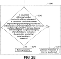
- FIG. 2B shows a detailed flowchart of step S240 according to an embodiment.
- step S240 in FIG. 2B may include steps S242, S244 and S246.
- the characteristic calculating module 110 determines whether a coulombic efficiency of the battery 1021 is less than a coulombic efficiency threshold, whether a correlation coefficient between the aligned charging/discharging characteristic and the comparison characteristic is less than a correlation coefficient threshold, and/or whether a pairwise distance between the aligned charging/discharging characteristic and the comparison characteristic is greater than a pairwise distance threshold.
- the correlation coefficient is, for example, a Pearson's correlation coefficient.
- the pairwise distance is, for example, an Euclidean distance.
- a difference between the temperature information of the battery 1021 and comparison temperature information of the comparison characteristic is less than a temperature threshold, e.g., the temperature threshold is ⁇ 2°C.
- the charging/discharging characteristic is a differential capacity versus voltage (dQ/dV-V) relationship during a charging process of the battery 1021
- the comparison characteristic is a history charging characteristic of the battery 1021, e.g., the dQ/dV-V relationship during one previous charging process.
- the characteristic calculating module 110 calculates the correlation coefficient according to the dQ/dV-V relationship of the aligned charging process and the dQ/dV-V relationship of the previous charging process, and determines whether the correlation coefficient is less than the correlation coefficient threshold by comparing the two.
- the correlation coefficient threshold is between 0.95 and 1.
- the battery capacity is a battery capacity change during a charging process, e.g., the battery capacity change from the beginning to the end of the charging process;
- the quantity of data points is the number of sets of data of the charging process, e.g., the number of sets of charging voltage data or charging battery capacity data from the beginning to the end of the charging process.
- the characteristic calculating module 110 calculates the non-dimensional pairwise distance, and determines whether the non-dimensional pairwise distance is greater than a pairwise distance threshold by comparison.
- the pairwise distance threshold is between 2% and 5%.
- the characteristic calculating module 110 determines whether the coulombic efficiency of the battery 1021 is less than a coulombic efficiency threshold, whether the correlation coefficient between the aligned charging/discharging characteristic and the comparison characteristic is less than the correlation coefficient threshold, and whether the pairwise distance between the aligned charging/discharging characteristic and the comparison characteristic is greater than the pairwise distance threshold. If the characteristic calculating module 110 determines that all of the three above determination conditions are negative, the characteristic calculating module 110 determines that the battery 1021 is normal; if the characteristic calculating module 110 determines that one or more of the three determination conditions above is affirmative, the characteristic calculating module 110 determines that the battery 1021 is abnormal.
- the characteristic calculating module 110 determines whether the coulombic efficiency of the battery 1021 is less than a coulombic efficiency threshold, whether the correlation coefficient between the aligned charging/discharging characteristic and the comparison characteristic is less than a correlation coefficient threshold, or whether the pairwise distance between the aligned charging/discharging characteristic and the comparison characteristic is greater than the pairwise distance threshold.
- the characteristic calculating module 110 determines that one of the three determination conditions above is negative, the characteristic calculating module 110 determines that the battery 1021 is normal; when the characteristic calculating module 110 determines that all of the three determination conditions above are affirmative, the characteristic calculating module 110 determines that the battery 1021 is abnormal.
- the characteristic calculating module 110 may only determine whether the coulombic efficiency of the battery 1021 is less than a coulombic efficiency threshold to determine whether the battery 1021 is normal. In one embodiment, the characteristic calculating module 110 may only determine whether the correlation coefficient between the aligned charging/discharging characteristic and the comparison characteristic is less than the correlation coefficient threshold to determine whether the battery 1021 is normal. In one embodiment, the characteristic calculating module 110 may only determine whether the pairwise distance between the aligned charging/discharging characteristic and the comparison characteristic is greater than the pairwise distance threshold to determine whether the battery 1021 is normal. Step S244 is performed if the determination of step S242 is affirmative, otherwise step S246 is performed.
- the internal short-circuit resistance calculating module 112 calculates the resistance of the internal short circuit of the battery 1021.
- the internal short-circuit resistance calculating module 112 calculates a plurality of resistance values of the internal short circuit, which respectively correspond to a plurality of voltages in a voltage range.
- the internal short-circuit resistance calculating module 112 calculates a plurality of resistance values of the internal short circuit respectively corresponding to a plurality of sets of charging voltage information during one charging process, or calculates a plurality of resistance values of the internal short circuit respectively corresponding to a plurality of sets of discharging voltage information during one discharging process.
- the charging process or the discharging process includes the voltage range.
- step S246 the characteristic calculating module 110 determines the battery 1021 as being normal.
- the battery 1021 can be used normally and/or can normally charge and discharge.
- FIG. 3A to FIG. 3E show simulation schematic diagrams of a method for detecting resistance of an internal short circuit of a battery according to an embodiment.
- the DAQ module 106 measures charging/discharging information of the battery 1021.
- the charging/discharging information of the battery 1021 is charging information of a charging process, wherein the charging information includes charging voltage information, charging current information, charging time information and charging battery temperature information.
- the comparison characteristic is a history charging characteristic of the battery 1021, and the history charging characteristic is stored in the storage unit 108.
- the characteristic calculating module 110 calculates the charging/discharging characteristic of the battery 1021 according to the charging/discharging information.
- the charging/discharging characteristic includes a first charging/discharging characteristic and a second charging/discharging characteristic, the first charging/discharging characteristic is a dQ/dV-V relationship of the charging process, and the second charging/discharging characteristic is a Q-V relationship of the charging process.
- the characteristic calculating module 110 calculates the charging battery capacity information according to the charging current information and the charging time information. In FIG. 3A , the vertical axis is the battery capacity and the horizontal axis is the voltage.
- the characteristic calculating module 110 draws a Q-V relationship curve 304 of the charging process. In one embodiment, the characteristic calculating module 110 further draws a Q-V relationship curve 302 of one previous charging process. In one embodiment, the Q-V relationship curve 302 of the previous charging process may be stored in the storage unit 108.
- the characteristic calculating module 110 differentiates the charging battery capacity information with respect to the charging voltage information to obtain charging differential capacity information.
- the vertical axis is the differential capacity and the horizontal axis is the voltage.
- the characteristic calculating module 110 draws a dQ/dV-V relationship curve 314 of a charging process.
- the characteristic calculating module 110 further draws a dQ/dV-V relationship curve 312 of one previous charging process.
- the dQ/dV-V relationship curve 312 of the previous charging process may be stored in the storage unit 108.
- step S230 the characteristic calculating module 110 aligns the charging/discharging characteristic of the battery 1021 according to the comparison characteristic point of the comparison characteristic to obtain an aligned charging/discharging characteristic.
- the characteristic calculating module 110 aligns the first charging/discharging characteristic of the battery 1021 according to the comparison characteristic point of the comparison characteristic to obtain an aligned first charging/discharging characteristic, and aligns the second charging/discharging characteristic according to the aligned first charging/discharging characteristic to obtain an aligned second charging/discharging characteristic.
- the characteristic calculating module 110 aligns a first local maximum point 314A, a second local maximum point 314B and a third local maximum point 314C of the dQ/dV-V relationship curve 314 of the charging process in FIG. 3B with a first local maximum point 312A, a second local maximum point 312B and a third local maximum point 312C of the dQ/dV-V relationship curve 312 of the previous charging process, e.g., shifting to the left, to obtain a dQ/dV-V relationship curve 314' of an aligned charging process, as shown in FIG. 3C .
- FIG. 3C Referring to FIG.
- the first local maximum point 314A, the second local maximum point 314B and the third local maximum point 314C of the dQ/dV-V relationship curve 314 of the charging process in FIG. 3B become a first local maximum point 314A', a second local maximum point 314B' and a third local maximum point 314C' of the dQ/dV-V relationship curve 314' of the aligned charging process in FIG. 3C after the alignment,.
- the horizontal-axis coordinates of the first local maximum point 314A', the second local maximum point 314B' and the third local maximum point 314C' of the dQ/dV-V relationship curve 314' of the aligned charging process are substantially identical to the horizontal-axis coordinates of the first local maximum point 312A, the second local maximum point 312B and the third local maximum point 312C of the dQ/dV-V relationship curve 312 of the previous charging process.
- the characteristic calculating module 110 further aligns the Q-V relationship curve 304 of the charging process according to the dQ/dV-V relationship curve 314' of the aligned charging process to obtain a Q-V relationship curve 304' of an aligned charging process. For example, the characteristic calculating module 110 shifts the Q-V relationship curve 304 of the charging process to the left according to a difference between the horizontal-axis coordinates of the first local maximum point 314A of the dQ/dV-V relationship curve 314 of the charging process and the first local maximum point 314A' of the dQ/dV-V relationship curve 314' of the aligned charging process, to obtain a Q-V relationship curve 304' of the aligned charging process, as shown in FIG. 3D .
- Aligned charging information can be obtained after the alignment.
- aligned charging voltage information and aligned charging battery capacity information can be obtained after the alignment.
- step S240 the characteristic calculating module 110 determines whether the battery 1021 is normal according to the aligned charging/discharging characteristic or the coulombic efficiency of the battery 1021; when it is determined that the battery 1021 is abnormal, the internal short-circuit resistance calculating module 112 calculates aligned charging/discharging information, and calculates the resistance of the internal short circuit of the battery 1021 according to the aligned charging/discharging information. Details for determining whether the battery 1021 is normal can be referred from the description of step S242 in FIG. 2 . In this embodiment, details for calculating the resistance of the internal short circuit of the battery 1021 are given below. As shown in FIG.
- the aligned charging battery capacity information corresponding to the aligned charging voltage V 1 is Q c1
- the battery capacity information of the comparison characteristic corresponding to the aligned charging voltage V 1 is Q r1
- the aligned charging battery capacity information Q c2 corresponding to the aligned charging voltage V 2 is Q c2
- the battery capacity information of the comparison characteristic corresponding to the aligned charging voltage V 2 is Q r2 .
- the charging time information corresponding to the aligned charging voltage V 1 is t 1
- the charging time information corresponding to the aligned charging voltage V 2 is t 2 .
- a current of the internal short circuit I isc12 ⁇ Q 12 / ⁇ t.
- V isc12 may be V 1 or V 2 , or may be an average of V 1 and V 2 .
- a relationship curve 346 of the calculated the resistance of the internal short circuit and the aligned charging voltage is as shown in FIG. 3E .
- the internal short-circuit resistance calculating module 112 calculates a plurality of calculated resistance values of the internal short circuit in the charging voltage interval, wherein the plurality of calculated resistance values of the internal short circuit have a corresponding relationship with the aligned charging voltages in the charging voltage interval.
- the charging voltage interval may include all voltages in the charging process, or may include a part of the voltages in the charging process.
- the resistance values of the internal short circuit corresponding to the interval between 3.25 V and 4.2 V may be calculated, or the calculated resistance values of the internal short circuit corresponding to the interval between 3.62 V and 4.12 V may be calculated.
- the resistance values of the internal short circuit corresponding to all measured voltages in the charging process can be calculated in one charging process.
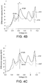
- FIG. 4A to FIG. 4E show simulation schematic diagrams of a method for detecting resistance of an internal short circuit of a battery according to another embodiment.
- the DAQ module 106 measures charging/discharging information of the battery 1021.
- the charging/discharging information of the battery 1021 is discharging information of a discharging process, wherein the discharging information includes discharging voltage information, discharging current information, discharging time information and discharging battery temperature information.
- the comparison characteristic is a charging characteristic of the battery 1021.
- the characteristic calculating module 110 calculates the charging/discharging characteristic of the battery 1021 according to the charging/discharging information.
- the charging/discharging characteristic includes a first charging/discharging characteristic and a second charging/discharging characteristic, the first charging/discharging characteristic is a dQ/dV-V relationship of a discharging process, and the second charging/discharging characteristic is a Q-V relationship of the discharging process.
- the comparison characteristic includes a first comparison characteristic and a second comparison characteristic, the first comparison characteristic is a dQ/dV-V relationship of a charging process, and the second comparison characteristic is a Q-V relationship of the charging process.
- the characteristic calculating module 110 calculates the discharging battery capacity information according to the discharging current information and the discharging time information.
- the vertical axis is the battery capacity and the horizontal axis is the voltage.
- the characteristic calculating module 110 draws a Q-V relationship curve 404 of the discharging process.
- the characteristic calculating module 110 further draws a Q-V relationship curve 402 of the charging process.
- the Q-V relationship curve 402 of the charging process may be stored in the storage unit 108.
- the characteristic calculating module 110 differentiates the charging battery capacity information with respect to the discharging voltage information to obtain discharging differential capacity information.
- the vertical axis is the differential capacity and the horizontal axis is the voltage.
- the characteristic calculating module 110 draws a dQ/dV-V relationship curve 414 of the discharging process.
- the characteristic calculating module 110 draws a dQ/dV-V relationship curve 412 of a charging process.
- the dQ/dV-V relationship curve 412 of the charging process may be stored in the storage unit 108.
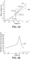
- step S240 the characteristic calculating module 110 determines whether the battery 1021 is normal according to the aligned charging/discharging characteristic or the coulombic efficiency of the battery 1021; when it is determined that the battery 1021 is abnormal, the internal short-circuit resistance calculating module 112 calculates aligned charging/discharging information, and calculates the resistance of the internal short circuit of the battery 1021 according to the aligned charging/discharging information. Details for determining whether the battery 1021 is normal can be referred from the description of step S242 in FIG. 2 . In this embodiment, details for calculating the resistance of the internal short circuit are given as below. As shown in FIG.
- the aligned discharging battery capacity information corresponding to the aligned discharging voltage V 3 is Q d3
- the charging battery capacity information corresponding to the aligned discharging voltage V 3 is Q c3
- the aligned discharging battery capacity information corresponding to the aligned discharging voltage V 4 is Q d4
- the charging battery capacity information corresponding to the aligned discharging voltage V 4 is Q c4 .
- ⁇ Q n is, when the battery 1021 is normal, a normal charging battery capacity or a normal discharging battery capacity in an interval between the aligned discharging voltage V 3 to the aligned discharging voltage V 4 , and the normal charging battery capacity is equal to the normal discharging battery capacity;
- ⁇ Q cisc is a charging battery capacity caused by an internal short circuit of the battery in an interval of charging from the aligned discharging voltage V 3 to the aligned discharging voltage V 4 ;
- ⁇ Q disc is a discharging battery capacity caused by an internal short circuit of the battery in an interval of discharging from the aligned discharging voltage V 3 to the aligned discharging voltage V 4 .
- the internal short-circuit resistance calculating module 112 calculates a plurality of calculated resistance values of the internal short circuit in the discharging voltage interval, wherein the plurality of calculated the resistance values of the internal short circuit have a corresponding relationship with the aligned discharging voltages in the discharging voltage interval.
- the discharging voltage interval may include all voltages in the discharging process, or may include a part of the voltages in the discharging process.
- the discharging process is discharging from 4.2 V to 3.25 V
- all of the calculated the resistance values of the internal short circuit corresponding to the interval between 4.2 V and 3.25 V may be calculated, or the calculated resistance values of the internal short circuit corresponding to the interval between 4.152 V and 3.9 V may be calculated.
- the resistance values of the internal short circuit corresponding to all measured voltages in the discharging process can be calculated.
- FIG. 5A shows a flowchart of a method for determining a discharging process of the battery 1021 according to an embodiment.
- FIG. 1B FIG. 1D and FIG. 5A
- details of steps S210, S220 and S230 in FIG. 5A may be referred from the description associated with FIG. 1A , FIG. 2B , FIG. 3A to FIG. 3E , and FIG. 4A to FIG. 4E .
- step S250 is performed after step S230.
- the characteristic calculating module 110 is configured to determine whether the battery 1021 is normal according to the aligned charging/discharging characteristic or the coulombic efficiency of the battery 1021; when it is determined that the battery 1021 is abnormal, the safety probability calculating module 114 is configured to calculate a safety probability of the battery 1021 according to the aligned charging/discharging characteristic and the resistance of the internal short circuit of the battery 1021.
- the resistance of the internal short circuit of the battery 1021 may be calculated according to the above embodiments, or may be fetched from the storage unit 108.
- Step S260 is performed after step S250.
- the safety probability calculating module 114 is configured to determine a discharging process of the battery 1021 according to the safety probability of the battery 1021.
- FIG. 5B shows a detailed flowchart of step S250 according to an embodiment.
- step S250 includes steps S252, S254 and S256. Details of step S252 may be referred from the description associated with step S242 in FIG. 2B .
- Step S254 is performed if the determination of step S252 is affirmative, otherwise step S256 is performed. In one embodiment, if the determination of step S252 is affirmative, the battery 1021 is no longer charged.
- the safety probability calculating module 114 calculates a correlation coefficient safety probability of the battery 1021 according to a correlation coefficient between the aligned charging/discharging characteristic and the comparison characteristic, and/or calculates a pairwise distance safety probability of the battery 1021 according to a pairwise distance between the aligned charging/discharging characteristic and the comparison characteristic.
- the charging/discharging characteristic is a Q-V relationship of a charging process of the battery 1021
- the comparison characteristic is a history charging characteristic, e.g., a Q-V relationship of one previous charging process of the battery 1021.
- step S252 the pairwise distance of the battery 1021 is calculated according to the Q-V relationship of the aligned charging process and the Q-V relationship of the previous charging process.
- the safety probability calculating module 114 constructs a pairwise distance graph by taking the value of the pairwise distance as the vertical axis and taking the resistance or the log of the resistance as the horizontal axis, marks the pairwise distance of the battery 1021 and the resistance of the internal short circuit of the battery 1021 in the pairwise distance graph of the battery 1021, and determines a pairwise distance safety determination range.
- the safety probability calculating module 114 stores the pairwise distance of the battery 1021 and the corresponding resistance values of the internal short circuit of the battery 1021 and/or the events of the battery 1021 (e.g., "abnormal but safe", “abnormal and overheated", or "abnormal and burned") in the storage unit 108 to serve as one set of pairwise distance information for the next determination.
- the charging/discharging characteristic is a dQ/dV-V relationship of a charging process of the battery 1021
- the comparison characteristic is a history charging characteristic of the battery 1021, e.g., a dQ/dV-V relationship of one previous charging process.
- the characteristic calculating module 110 calculates the correlation coefficient of the battery 1021 according to the dQ/dV-V relationship of the aligned charging process and the dQ/dV-V relationship of the previous charging process.
- the safety probability calculating module 114 constructs a correlation coefficient graph by taking the number of correlation coefficients as the vertical axis and the resistance or the log of the resistance as the horizontal axis, marks the correlation coefficients of the battery 1021 and the resistance values of the internal short circuit of the battery 1021 in the correlation coefficient graph, and determines a correlation coefficient safety determination range.
- the storage unit 108 stores a plurality of sets of correlation coefficient information, e.g., history correlation coefficients of the battery 1021 and the corresponding resistance values of an internal short circuit, or correlation coefficients of another battery and the corresponding resistance values of an internal short circuit.
- the another battery is a battery of the same manufacturer brand and/or of the same model as the battery 1021.
- the characteristic calculating module 110 determines that the battery 1021 is normal.
- the battery 1021 can be used normally and/or can charge and discharge normally.
- the safety probability calculating module 114 stores the pairwise distances of the battery 1021, the corresponding resistance values of an internal short circuit of the battery 1021, and/or events of the battery 1021 (e.g., "normal") in the storage unit 108 to serve as one set of pairwise distance information for the next determination.
- the safety probability calculating module 114 stores the correlation coefficients of the battery 1021, the corresponding resistance values of an internal short circuit of the battery 1021, and/or events of the battery 1021 (e.g., "normal") in the storage unit 108 to serve as one set of correlation coefficient information for the next determination.
- FIG. 5C shows a detailed flowchart of step S260 according to an embodiment.
- step S260 includes steps S262, S264 and S266.
- step S262 if the safety probability calculating module 114 determines that the correlation coefficient safety probability is greater than the correlation coefficient safety probability threshold, step S262 is determined to be affirmative, and the pairwise distance safety probability does not need to be determined. In one embodiment, if the safety probability calculating module 114 determines that the pairwise distance safety probability is greater than the pairwise distance safety probability threshold, step S262 is determined to be affirmative, and the correlation coefficient safety probability does not need to be determined. Step S266 is performed if step S262 is determined to be affirmative, otherwise step S264 is performed if step S262 is determined to be negative.
- step S264 the battery 1021 is discharged by using an abnormal discharging circuit 116.
- the battery 1021 is no longer charged after it has been discharged.
- the switch 1164 by using the switch 1164, the first end 1162A of the variable resistor 1162 and the first end 102A of the battery 1021 are connected, and the second end 1162B of the variable resistor 1162 and the second end 102B of the battery 1021 are connected, such that the battery 1021 is allowed to discharge to the variable resistor 1162.
- the battery 1021 is normally discharged.
- the battery 1021 when the battery 1021 is under normal use, the battery 1021 is no longer charged after it has been discharged.
- the battery 1021 is a battery in a cell phone
- the cell phone can be used normally until the power in the battery 1021 is depleted and then the battery 1021 is no longer charged.
- the switch 1164 by using the switch 1164, the variable resistor 1162 and the battery 1021 are not connected, such that the battery 1021 is allowed to discharge normally.
- FIG. 6A shows a pairwise distance graph 600 of the battery 1021 according to an embodiment.
- the horizontal axis (X-axis) represents the log (log 10 R) of the resistance, wherein the base of the log is 10, and the vertical axis (Y-axis) represents the pairwise distance value.
- the base of the log of the resistance may be 2 or other values instead of 10.
- the battery 1021 is determined as being abnormal in step S252, and the pairwise distances of the battery 1021 and the resistance values of the internal short circuit of the battery 1021 are marked in the pairwise distance graph 600 in step S254 to become an abnormal point 602.
- the pairwise distance graph 600 in addition to the abnormal point 602, a plurality of sets of pairwise distance information are further included.
- the pairwise distance information of a battery of the same manufacturer brand and the same model as the battery 1021 is also marked in the pairwise distance graph 600, and the pairwise distance information is categorized into "normal”, “abnormal but no safety event", "abnormal and overheated", and "abnormal and burned”.
- the pairwise distance safety probability is ((quantity of normal + quantity of abnormal but no safety events) / (quantity of normal + quantity of abnormal but no safety events + quantity of abnormal and overheated + quantity of abnormal and burned)) * 100%; the pairwise distance safety probability threshold is 90%.
- the safety probability calculating module 114 counts 7 sets of pairwise distance information within the pairwise distance safety determination range 604. Among the 7 sets of pairwise distance information, 0 is "normal", 4 are “abnormal but no safety event", 3 are “abnormal and overheated”, and 0 is "abnormal and burned”.
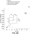
- FIG. 6B shows a correlation coefficient graph 610 of the battery 1021 according to an embodiment.
- the horizontal axis (X-axis) represents the log (log 10 R) of the resistance, wherein the base of the log is 10, and the vertical axis (Y-axis) represents the correlation coefficient.
- the base of the log of the resistance may be 2 or other values instead of 10.
- the battery 1021 is determined as being abnormal in step S252, and the correlation coefficient of the battery 1021 and the resistance value of the internal short circuit of the battery 1021 are marked in the correlation coefficient graph 610 in step S254 to become an abnormal point 612.
- the correlation coefficient graph 610 in addition to the abnormal point 612, a plurality of sets of correlation coefficient information are further included.
- the correlation coefficient information of a battery of the same manufacturer brand and the same model as the battery 1021 is also marked in the correlation coefficient graph 610, and the correlation coefficient information is categorized into "normal”, “abnormal but no safety event", “abnormal and overheated", and "abnormal and burned”.
- the correlation coefficient safety determination range 614 is constructed between the X-axis coordinates (X 612 -R d3 ) and (X 612 +R d4 ) and between the Y-axis coordinates (Y 612 -C d2 ) and (Y 612 +C d2 ).
- the third resistance error R d3 and the fourth resistance error R d4 may be the same or different, and the first correlation coefficient error C d1 and the second correlation coefficient error C d2 may be the same or different.
- FIG. 7 shows a flowchart of a method for determining a discharging process of the battery 1021 according to an embodiment.
- the characteristic calculating module 110 determines that the battery 1021 is abnormal.
- the safety probability calculating module 114 is configured to determine a safety determination range according to the relationship between the battery capacity and resistance of the battery 1021, and/or the relationship between the differential capacity and resistance of the battery 1021, and calculate the safety probability of the battery according to the quantity and danger levels of a plurality of sets of event information in the safety determination range.
- FIG. 8 shows a flowchart of a method for detecting resistance of an internal short circuit of the battery 1021 and a method for determining a discharging process of the battery 1021 according an embodiment.
- the DAQ module 106 measures charging/discharging information of the battery 1021.
- the characteristic calculating module 110 calculates a charging/discharging characteristic according to the charging/discharging information of the battery 1021.
- the characteristic calculating module 110 aligns the charging/discharging characteristic of the battery 1021 according to a comparison characteristic point of a comparison characteristic to obtain an aligned charging/discharging characteristic.
- a function of detecting an internal short circuit of a battery at an early stage is provided.
- a battery system is able to detect whether a characteristic in a current charging or discharging interval is changed to further analyze whether an internal short circuit occurs and calculate the resistance of the internal short circuit
- a function of detecting an internal short circuit of a battery at an early stage is provided.
- a battery system is able to detect whether a characteristic in a current charging or discharging interval is changed, such that a safety probability value can be calculated when the internal short circuit is moderate at an early stage so as to provide appropriate early warning and reactive measures.
Landscapes
- Engineering & Computer Science (AREA)
- Physics & Mathematics (AREA)
- General Physics & Mathematics (AREA)
- Power Engineering (AREA)
- Transportation (AREA)
- Mechanical Engineering (AREA)
- Manufacturing & Machinery (AREA)
- Electrochemistry (AREA)
- General Chemical & Material Sciences (AREA)
- Chemical Kinetics & Catalysis (AREA)
- Chemical & Material Sciences (AREA)
- Life Sciences & Earth Sciences (AREA)
- Sustainable Development (AREA)
- Sustainable Energy (AREA)
- Charge And Discharge Circuits For Batteries Or The Like (AREA)
- Secondary Cells (AREA)
Abstract
Description
- The disclosure relates to a method and a system for determining a discharging process of a battery.
- With the ever-progressing technologies, more and more electronic devices, power storage systems and electric vehicles are equipped with batteries. An abnormality of a battery may cause the battery burning, putting a user into danger and making huge losses to manufacturers. Therefore, there is a need for a solution for determining whether a battery is abnormal and determining a discharging process of the battery.
- The disclosure is directed to a method and a system for determining a discharging process of a battery.
- According to an embodiment, a method for determining a discharging process of a battery is provided. The method includes steps of: measuring charging/discharging information of a battery; calculating a charging/discharging characteristic of the battery according to the charging/discharging information; aligning the charging/discharging characteristic of the battery according to a comparison characteristic point of a comparison characteristic to obtain an aligned charging/discharging characteristic; determining whether the battery is normal according to the aligned charging/discharging characteristic or a coulombic efficiency of the battery; calculating a safety probability of the battery according to the aligned charging/discharging characteristic and resistance of an internal short circuit of the battery when the battery is determined as being abnormal; and determining a discharging process of the battery according to the safety probability of the battery.
- According to another embodiment, a system for determining a discharging process of a battery is provided. The system for detecting resistance of an internal short circuit of a battery includes a battery set, a data acquisition (DAQ) module, a characteristic calculating module and a safety probability calculating module. The battery set includes a battery. The DAQ module is configured to measure charging/discharging information of the battery. The characteristic calculating module is configured to calculate a charging/discharging characteristic of the battery according to the charging/discharging information, align the charging/discharging characteristic according to a comparison characteristic point of a comparison characteristic to obtain an aligned charging/discharging characteristic, and determine whether the battery is normal according to the aligned charging/discharging characteristic or a coulombic efficiency of the battery. The safety probability calculating module is configured to calculate a safety probability of the battery according to the aligned charging/discharging characteristic and resistance of internal short circuit of the battery, and determine a discharging process of the battery according to the safety probability
- According to another embodiment, a method for determining a discharging process is provided. The method for determining the discharging process includes: determining that a battery is abnormal; determining a safety determination range according to a battery capacity versus resistance relationship or a differential capacity versus resistance relationship, and calculating a safety probability of the battery according to danger levels and a quantity of events in the safety determination range; and determining the discharging process of the battery according to the safety probability of the battery.
- To better understand the disclosure, preferred embodiments are given in detail with the accompanying drawings below.
-
-
FIG. 1A is a schematic diagram of a system for detecting resistance of an internal short circuit of a battery according to an embodiment; -
FIG. 1B is a schematic diagram of a system for determining a discharging process of a battery according to an embodiment; -
FIG. 1C is a schematic diagram of a system for detecting resistance of an internal short circuit and determining a discharging process of a battery according to an embodiment; -
FIG. 1D is a schematic diagram of a battery set and an abnormal discharging circuit according to an embodiment; -
FIG. 1E is a schematic diagram of a battery set and an abnormal discharging circuit according to another embodiment; -
FIG. 2A is a flowchart of a method for detecting resistance of an internal short circuit of a battery according to an embodiment; -
FIG. 2B is a detailed flowchart of step S240 according to an embodiment; -
FIGS. 3A to 3E are simulation schematic diagrams of a method for detecting resistance of an internal short circuit of a battery according to an embodiment; -
FIGS. 4A to 4E are simulation schematic diagrams of a method for detecting resistance of an internal short circuit of a battery according to another embodiment; -
FIG. 5A is a flowchart of a method for determining a discharging process of a battery according to an embodiment; -
FIG. 5B is a detailed flowchart of step S250 inFIG. 5A according to an embodiment; -
FIG. 5C is a detailed flowchart of step S260 inFIG. 5A according to an embodiment; -
FIG. 6A is a pairwise distance graph of a battery according to an embodiment; -
FIG. 6B is a correlation coefficient graph of a battery according to an embodiment; -
FIG. 7 is a flowchart of a method for determining a discharging process of a battery according to an embodiment; and -
FIG. 8 is a flowchart of a method for detecting resistance of an internal short circuit of a battery and a method for determining a discharging process of a battery according to an embodiment. - In the following detailed description, for purposes of explanation, numerous specific details are set forth in order to provide a thorough understanding of the disclosed embodiments. It will be apparent, however, that one or more embodiments may be practiced without these specific details. In other instances, well-known structures and devices are schematically shown in order to simplify the drawing.
- Technical terms of the application are based on general definition in the technical field of the application. If the application describes or explains one or some terms, definition of the terms are based on the description or explanation of the application. Each embodiment of the disclosure includes one or more technical features. In possible implementation, one person skilled in the art can selectively implement a part or all of the technical features of any of the embodiments, or selectively combine a part or all of the technical features of the embodiments.
-
FIG. 1A shows a schematic diagram of asystem 100 for detecting resistance of an internal circuit of a battery according to an embodiment. In this embodiment, thesystem 100 for detecting resistance of an internal circuit of a battery is suitable for detecting resistance of an internal short circuit (ISC) of a battery. In this embodiment, thesystem 100 for detecting resistance of an internal circuit of a battery includes abattery set 102, acharging circuit 104, a data acquisition (DAQ)module 106, astorage unit 108, a characteristic calculatingmodule 110 and an internal short-circuitresistance calculating module 112. In one embodiment, thesystem 100 for detecting resistance of an internal circuit of a battery may further include an abnormal discharging circuit (not shown) that is coupled to the characteristic calculatingmodule 110. In one embodiment, thesystem 100 for detecting resistance of an internal circuit of a battery may be placed in a mobile device, e.g., a cell phone, a personal digital assistant (PDA), a tablet computer, a laptop computer, a point-of-sales (POS) machine, a portable media player, a digital camera or a wearable device. In one embodiment, thesystem 100 for detecting resistance of an internal circuit of a battery may also be placed in a vehicle, e.g., an automobile, a motorcycle, an aircraft, a boat, a submarine, an unmanned automobile, a drone or an unmanned boat. In one embodiment, thesystem 100 for detecting resistance of an internal circuit of a battery may also be placed in a toy or a model of any of the above vehicles. - The battery set 102 is coupled to the charging
circuit 104 and theDAQ module 106, and includes one or multiple batteries. The batteries of the battery set 102 are formed in a serial, parallel or array structure. For example, the array structure may be the reconfigurable array of inexpensive batteries architecture (RAIBA) technique. In one embodiment, the above batteries may be rechargeable batteries such as lithium-ion batteries, lithium metal batteries, lead-acid batteries, nickel-cadmium batteries, nickel-metal hydride batteries, or may be super capacitors, fuel cells or solar cells. - The charging
circuit 104 is coupled to the battery set 102, and may be a circuit or a switch. The chargingcircuit 104 is capable of charging or terminating the charging of the batteries in thebattery set 102. In one embodiment, the chargingcircuit 104 may be provided outside thesystem 100 for detecting resistance of an internal short circuit of a battery. - The
DAQ module 106 is coupled to the battery set 102 and thecharacteristic calculating module 110. TheDAQ module 106 may be one or multiple separate or integrated meters or sensors, e.g., a voltmeter, an ammeter, a temperature sensor and/or a time recorder. In one embodiment, theDAQ module 106 may be a detection circuit. In one embodiment, theDAQ module 106 may be an independent device or instrument outside thesystem 100 for detecting resistance of an internal short circuit of a battery. In one embodiment, theDAQ module 106 may measure and/or record a voltage, a current, a temperature or a time of the batteries in the battery set by using the above meters, sensors, detection circuits, devices and/or instruments. - The
storage unit 108 is coupled to thecharacteristic calculating module 110. Thestorage unit 108 may be a hardware unit, e.g., a memory, a hard drive, a solid-state disk (SSD), a flash memory or a read-only memory (ROM). - The
characteristic calculating module 110 is coupled to theDAQ module 106, thestorage unit 108 and the internal short-circuitresistance calculating module 112. Thecharacteristic calculating module 110 may be a hardware circuit, a software module executed by a processor (not shown) or a controller (not shown), or partly a circuit and partly a software module executed by a processor or a controller. Details of the function of thecharacteristic calculating module 110 are to be described shortly. - The internal short-circuit
resistance calculating module 112 is coupled to thecharacteristic calculating module 110. The internal short-circuitresistance calculating module 112 may be a hardware circuit, a software module executed by a processor (not shown) or a controller (not shown), or partly a circuit and partly a software module executed by a processor or a controller. Details of the function of the internal short-circuitresistance calculating module 112 are to be described shortly. In one embodiment, thecharacteristic calculating module 110 and the internal short-circuitresistance calculating module 112 may be integrated into one module. -
FIG. 1B shows a schematic diagram of asystem 200 for determining a discharging process of a battery according to an embodiment of the present invention. In this embodiment, thesystem 200 for determining a discharging process of a battery is suitable for determining a discharging process of a battery. In this embodiment, thesystem 200 for determining a discharging process of a battery includes abattery set 102, a chargingcircuit 104, aDAQ module 106, astorage unit 108, acharacteristic calculating module 110, a safetyprobability calculating module 114 and an abnormal dischargingcircuit 116. In one embodiment, thesystem 200 for determining a discharging process of a battery may be placed in a mobile device, e.g., a cell phone, a PDA, a tablet computer, a laptop computer, a POS machine, a portable media player, a digital camera, or a wearable device. In one embodiment, thesystem 200 for determining a discharging process of a battery may also be placed in a vehicle, e.g., an automobile, a motorcycle, an aircraft, a boat, a submarine, an unmanned automobile, a drone or an unmanned boat. In one embodiment, thesystem 200 for determining a discharging process of a battery may also be placed in a toy or a model of any of the above vehicles. The battery set 102, the chargingcircuit 104, theDAQ module 106, thestorage unit 108 and thecharacteristic calculating module 110 inFIG. 1B are identical or similar to the chargingcircuit 104, theDAQ module 106, thestorage unit 108 and thecharacteristic calculating module 110 inFIG. 1A , and associated details can be referred from the corresponding description. In this embodiment, thecharacteristic calculating module 110 is coupled to theDAQ module 106, thestorage unit 108 and the safetyprobability calculating module 114. - The safety
probability calculating module 114 is coupled to thecharacteristic calculating module 110, thestorage unit 108 and the abnormal dischargingcircuit 116. The safetyprobability calculating module 114 may be a hardware circuit, a software module executed by a processor (not shown) or a controller (not shown), or partly a circuit and partly a software module executed by a processor or a controller. Details of the function of the safetyprobability calculating module 114 are to be described shortly. In one embodiment, thecharacteristic calculating module 110 and the safetyprobability calculating module 114 may be integrated into one module. - The abnormal discharging
circuit 116 is coupled to the battery set 102 and the safetyprobability calculating module 114. The abnormal dischargingcircuit 116 may include one or multiple variable resistors, one or multiple fixed resistors, or a combination of one or multiple variable resistors and/or one or multiple fixed resistors that are connected in series or in parallel. In one embodiment, the abnormal dischargingcircuit 116 may include a circuit consisting of one or multiple active components or other passive components. Active components are, e.g., metal-oxide-semiconductor field-effect transistors (MOSFETs) or bipolar transistors, and passive components are, e.g., inductors or capacitors. -
FIG. 1C shows a schematic diagram of asystem 300 for detecting resistance of an internal short circuit of a battery and determining a discharging process of a battery according to an embodiment of the present invention. In this embodiment, thesystem 300 for detecting resistance of an internal short circuit of a battery and determining a discharging process of a battery is suitable for calculating resistance of an internal short circuit of a battery and/or determining a discharging process of a battery. In this embodiment, thesystem 300 for detecting resistance of an internal short circuit of a battery and determining a discharging process of a battery includes abattery set 102, a chargingcircuit 104, aDAQ module 106, astorage unit 108, acharacteristic calculating module 110, an internal short-circuitresistance calculating module 112, a safetyprobability calculating module 114 and an abnormal dischargingcircuit 116. In one embodiment, thesystem 300 for detecting resistance of an internal short circuit of a battery and determining a discharging process of a battery may be placed in a mobile device, e.g., a cell phone, a PDA, a tablet computer, a laptop computer, a POS machine, a portable media player, a digital camera, or a wearable device. In one embodiment, thesystem 300 for detecting resistance of an internal short circuit of a battery and a discharging process of a battery may also be placed in a vehicle, e.g., an automobile, a motorcycle, an aircraft, a boat, a submarine, an unmanned automobile, a drone or an unmanned boat. In one embodiment, thesystem 300 for detecting resistance of an internal short circuit of a battery and a discharging process of a battery may also be placed in a toy or a model of any of the above vehicles. The battery set 102, the chargingcircuit 104, theDAQ module 106, thestorage unit 108, thecharacteristic calculating module 110 and the internal short-circuitresistance calculating module 112 inFIG. 1C are identical or similar to the chargingcircuit 104, theDAQ module 106, thestorage unit 108, thecharacteristic calculating module 110 and the internal short-circuitresistance calculating module 112 inFIG. 1A , and associated details can be referred from the corresponding description. The safetyprobability calculating module 114 and the abnormal dischargingcircuit 116 inFIG. 1C are identical or similar to the safetyprobability calculating module 114 and the abnormal dischargingcircuit 116 inFIG. 1B , and associated details can be referred from the corresponding description. In this embodiment, thecharacteristic calculating module 110 is coupled to theDAQ module 106, thestorage unit 108, the internal short-circuitresistance calculating module 112 and the safetyprobability calculating module 114. The internal short-circuitresistance calculating module 112 is coupled to thecharacteristic calculating module 110 and the safetyprobability calculating module 114. The safetyprobability calculating module 114 is coupled to thecharacteristic calculating module 110, the internal short-circuitresistance calculating module 112 and the abnormal dischargingcircuit 116. In one embodiment, thecharacteristic calculating module 110, the internal short-circuitresistance calculating module 112 and the safetyprobability calculating module 114 may be integrated into one module. -
FIG. 1D shows a schematic diagram of abattery set 102 and an abnormal dischargingcircuit 116 according to an embodiment. In this embodiment, the battery set 102 includes abattery 1021; the abnormal dischargingcircuit 116 includes avariable resistor 1162 and aswitch 1164. The abnormal dischargingcircuit 116 can be controlled to discharge thebattery 1021. For example, afirst end 1162A of thevariable resistor 1162 and afirst end 102A of thebattery 1021 may be connected, and asecond end 1162B of thevariable resistor 1162 and asecond end 102B of thebattery 1021 are connected, so as to allow thebattery 1021 to discharge to thevariable resistor 1162. In one embodiment, the resistance of thevariable resistor 1162 is adjustable. When thebattery 1021 is abnormal, the resistance of thevariable resistor 1162 may be adjusted to a minimum value (or a predetermined small resistance value) so as to accelerate the speed of discharging thebattery 1021. In one embodiment, when the battery set 102 is under normal use, the resistance of thevariable resistor 1162 may be adjusted to a maximum value (or a predetermined large resistance value) or is disconnected from the battery of the battery set 102, so as to prevent or reduce the discharging of the battery set 102 via thevariable resistor 1162. -
FIG. 1E shows a schematic diagram of abattery set 102 and an abnormal dischargingcircuit 116 according to another embodiment. In this embodiment, the battery set 102 includes abattery 1022, abattery 1023, abattery 1024, abattery 1025, abattery 1026 and abattery 1027; the abnormal dischargingcircuit 116 includes avariable resistor 1162 and aswitch 1164. The abnormal dischargingcircuit 116 can be controlled to discharge an individual battery or batteries in combination. For example, afirst end 1162A of thevariable resistor 1162 and afirst end 102C of thebattery 1022 are connected, and asecond end 1162B of thevariable resistor 1162 and asecond end 102D of thebattery 1022 are connected, so as to allow thebattery 1022 to discharge to thevariable resistor 1162. In one embodiment, the resistance of thevariable resistor 1162 is adjustable. When a battery in a battery set is abnormal, e.g., when thebattery 1022 is abnormal, the resistance of thevariable resistor 1162 may be adjusted to a minimum value (or a predetermined small resistance value), so as to accelerate the speed of discharging an individual battery or batteries in combination. In one embodiment, when a battery set is under normal use, the resistance of thevariable resistor 1162 may be adjusted to a maximum value (or a predetermined large resistance value) or be disconnected from the battery of the battery set 102, so as to prevent or reduce the discharging of the battery set 102 via thevariable resistor 1162. -
FIG. 2A shows a flowchart of a method for detecting resistance of an internal short circuit of a battery according to an embodiment. Referring toFIG. 1A ,FIG. 1D ,FIG. 1E andFIG. 2A , in step S210, theDAQ module 106 is configured to measure charging/discharging information of a battery. The charging/discharging information includes voltage information, current information, time information and/or battery temperature information. In one embodiment, theDAQ module 106 may measure the charging/discharging information of one single battery individually, e.g., the charging/discharging information of thebattery 1022. In one embodiment, theDAQ module 106 may measure the charging/discharging information of multiple batteries respectively, e.g., the charging/discharging information of thebattery 1022 and the charging/discharging information of thebattery 1023. In one embodiment, theDAQ module 106 may measure combined charging/discharging information of multiple batteries, e.g., the charging/discharging information of thebattery 1022 and thebattery 1023 connected in series. Thebattery 1021 is taken as an example in the following description. In one embodiment, the voltage information includes a plurality of sets of voltage data, the current information includes a plurality of sets of current data, the time information includes a plurality of sets of time data, and the battery temperature information includes a plurality of sets of battery temperature data. The sets of voltage data, current data, time data and/or battery temperature data have a corresponding relationship. For example, corresponding to the time data ti, the voltage data is Vi, the current data is Ii and/or the battery temperature data is Ti. In one embodiment, the charging/discharging information includes charging information during a charging process of thebattery 1021 or discharging information during a discharging process of thebattery 1021. In one embodiment, the charging/discharging information may be charging information during a charging process of thebattery 1021, wherein the charging information includes charging voltage information, charging current information, charging time information and/or charging battery temperature information. The charging process is, for example, charging from a minimum voltage (e.g., 0 V) of thebattery 1021 to a maximum voltage (e.g., 4.2 V) of thebattery 1021. In one embodiment, the charging process is, for example, charging a predetermined low voltage of thebattery 1021 to a predetermined high voltage of thebattery 1021. In one embodiment, the charging process is, for example, charging from a current voltage (e.g., a user charges a cell phone when thebattery 1021 of the cell phone still has remaining power) of the battery to a maximum voltage, a predetermined high voltage or a voltage when the charging ends (e.g., a user terminates the charging of a cell phone when thebattery 1021 of the cell phone is not yet fully charged). In one embodiment, the charging process is, for example, first charging by a constant current (CC) to a predetermined voltage (e.g., 4.2 V) and then charging by a constant voltage (CV) until the current is very small (e.g., less than a predetermined current), and the charging is terminated. In one embodiment, the charging/discharging information may be discharging information during a discharging process of thebattery 1021, wherein the discharging information includes discharging voltage information, discharging current information, discharging time information and/or discharging battery temperature information. The discharging process is, for example, discharging from a maximum voltage (e.g., 4.2 V) of thebattery 1021 to a minimum voltage (e.g., 0 V) of thebattery 1021. In one embodiment, the discharging process is, for example, discharging from a predetermined high voltage of thebattery 1021 to a predetermined low voltage of thebattery 1021. In one embodiment, the discharging process is, for example, discharging from a current voltage (e.g., a user plays games on a cell phone) of thebattery 1021 to a minimum voltage, a predetermined lower voltage or a voltage when the discharging is terminated (e.g., a user finishes a game on a cell phone and turns off the cell phone). - Step S220 is performed after step S210. In step S220, the
characteristic calculating module 110 is configured to calculate a charging/discharging characteristic of thebattery 1021 according to the charging/discharging information. In one embodiment, the charging/discharging characteristic of thebattery 1021 includes a relationship between battery capacity information and the voltage information of thebattery 1021. In one embodiment, thecharacteristic calculating module 110 calculates battery capacity information of thebattery 1021 according to the current information and the time information of thebattery 1021. Thecharacteristic calculating module 110 further draws a battery capacity versus voltage (Q-V) relationship curve to obtain a battery capacity versus voltage (Q-V) relationship, differentiates the battery capacity information with respect to the voltage information to obtain differential capacity information, and draws a differential capacity (dQ/dV) versus voltage (dQ/dV-V) relationship curve to obtain a differential capacity versus voltage (dQ/dV-V) relationship. In one embodiment, the charging/discharging characteristic is a charging characteristic during a charging process of thebattery 1021, e.g., a Q-V relationship and/or a dQ/dV-V relationship during the charging process of thebattery 1021. More specifically, thecharacteristic calculating module 110 calculates charging battery capacity information according to charging current information and charging time information of thebattery 1021, e.g., multiplying the charging current information by the charging time information to obtain the charging battery capacity information, and draws a relationship curve of the charging battery capacity versus the charging voltage by using the charging battery capacity as the vertical axis and the charging voltage information as the horizontal axis to obtain the Q-V relationship during the charging process. In one embodiment, the charging voltage information includes a plurality of sets of charging voltage data, the charging current information includes a plurality of sets of charging current data, and the charging time information includes a plurality of sets of charging time data. Thus, the calculated charging battery capacity information has a corresponding number of sets of charging battery capacity data. In one embodiment, thecharacteristic calculating module 110 further differentiates the charging battery capacity information with respect to the charging voltage information to obtain charging differential capacity information, and draws a relationship curve of charging differential capacity versus charging voltage by using the charging differential capacity information as the vertical axis and the charging voltage information as the horizontal axis to obtain a differential capacity versus voltage relationship during the charging process. In one embodiment, the charging/discharging characteristic is a discharging characteristic of a discharging process, e.g., a battery capacity versus voltage (Q-V) relationship and/or a differential capacity (dQ/dV) versus voltage (dQ/dV-V) relationship during a discharging process of thebattery 1021. More specifically, thecharacteristic calculating module 110 calculates discharging battery capacity information of thebattery 1021 according to discharging current information and discharging time information of thebattery 1021, e.g., multiplying the discharging current information by the discharging time information to obtain discharging battery capacity information, and draws a discharging battery capacity versus discharging voltage relationship curve by using the discharging battery capacity information as the vertical axis and the discharging voltage information as the horizontal axis to obtain a Q-V relationship during the discharging process. Thecharacteristic calculating module 110 may further differentiate the discharging battery capacity information with respect to the discharging voltage information to obtain discharging differential capacity information, and draw a relationship curve of discharging differential capacity versus discharging voltage by using the discharging differential capacity information as the vertical axis and the discharging voltage information as the horizontal axis to obtain the dQ/dV-V relationship during the discharging process. - After step S220, step S230 is performed. In step S230, the
characteristic calculating module 110 is configured to align the charging/discharging characteristic of thebattery 1021 according to a comparison characteristic point of a comparison characteristic to obtain an aligned charging/discharging characteristic. For example, thecharacteristic calculating module 110 aligns the charging/discharging characteristic of thebattery 1021 with a comparison characteristic point of a comparison characteristic to obtain an aligned charging/discharging characteristic. In one embodiment, details of the alignment are as follows. The charging/discharging characteristic includes a relationship curve, which includes charging/discharging characteristic points. The relationship curve of the charging/discharging characteristic is shifted, such that the horizontal-axis coordinates and/or the vertical-axis coordinates of the charging/discharging characteristic points of the relationship curve of the charging/discharging characteristic are identical to the horizontal-axis coordinates and/or the vertical-axis coordinates of the comparison characteristic points of the comparison characteristic. In one embodiment, the comparison characteristic is stored in thestorage unit 108. In one embodiment, the charging/discharging characteristic of the battery is a charging characteristic or a discharging characteristic of thebattery 1021, and the comparison characteristic is a history charging characteristic of thebattery 1021 or a history discharging characteristic of thebattery 1021. In one embodiment, after it is determined that thebattery 1021 is normal in one previous charging process, the charging characteristic is stored as a history charging characteristic of thebattery 1021. In one embodiment, after it is determined that thebattery 1021 is normal in one previous discharging process, the discharging characteristic is stored as a history discharging characteristic of thebattery 1021. The comparison characteristic is a history charging characteristic of another battery or a history discharging characteristic of another battery. The another battery is, for example, a battery of the same manufacturer brand or of the same model as thebattery 1021. In one embodiment, the charging/discharging characteristic of thebattery 1021 is one of the charging characteristic and the discharging characteristic of thebattery 1021, and the comparison characteristic is the other of the charging characteristic and the discharging characteristic of thebattery 1021. For example, the charging/discharging characteristic of thebattery 1021 is the charging characteristic of thebattery 1021, and the comparison characteristic is the discharging characteristic of thebattery 1021. Alternatively, the charging/discharging characteristic of thebattery 1021 is the discharging characteristic of thebattery 1021, and the comparison characteristic is the charging characteristic of thebattery 1021. In one embodiment, the charging/discharging characteristic point is a local maximum point and/or a local minimum point of the charging/discharging characteristic. In one embodiment, the comparison characteristic point is a local maximum point and/or a local minimum point of the comparison characteristic point. In the description below, a differential capacity (dQ/dV) versus voltage (dQ/dV-V) relationship during a discharging process is taken as the charging/discharging characteristic, and a differential capacity (dQ/dV) versus voltage (dQ/dV-V) relationship during a charging process is taken as the comparison characteristic as an example, to illustrate details of aligning the charging/discharging characteristic point of the charging/discharging characteristic of thebattery 1021 with the comparison characteristic point of the comparison characteristic. Thecharacteristic calculating module 110 identifies a local maximum point of the relationship curve of discharging differential capacity versus discharging voltage as a discharging local maximum point, identifies a local maximum point of a relationship curve of charging differential capacity versus charging voltage as a charging local maximum point, and shifts the relationship curve of discharging differential capacity versus discharging voltage such that the horizontal-axis coordinate of the discharging local maximum point is substantially identical to the horizontal-axis coordinate of the charging local maximum point, thus completing the alignment. In this embodiment, the shifted relationship curve of discharging differential capacity versus discharging voltage is the aligned charging/discharging characteristic. In one embodiment, the number of the charging/discharging characteristic point and/or the comparison characteristic point may be more than one. A charging/discharging characteristic point having a largest error from the corresponding comparison characteristic point may be omitted, or different weightings may be assigned to different charging/discharging characteristic points for the alignment. - Step S240 is performed after step S230. In step S240, the
characteristic calculating module 110 is configured to determine whether thebattery 1021 is normal according to the aligned charging/discharging characteristic or a coulombic efficiency of thebattery 1021. When it is determined that thebattery 1021 is abnormal, the internal short-circuitresistance calculating module 112 is configured to calculate aligned charging/discharging information according to the aligned charging/discharging characteristic, and calculate the resistance of an internal short circuit of thebattery 1021 according to the aligned charging/discharging information. The aligned charging/discharging information includes aligned voltage information, aligned current information, aligned battery capacity information and/or aligned time information. In one embodiment, a discharging process of thebattery 1021 may be determined according to the calculated resistance of the internal short circuit, and thebattery 1021 may be discharged according to the determined discharging process. In one embodiment, the voltage information has a corresponding relationship with the current information and/or the battery capacity information, and the aligned voltage information also has a corresponding relationship with the aligned current information and/or the aligned battery capacity information. In one embodiment, the current information and/or the battery capacity information, but not the voltage information, is adjusted during the alignment, so as to adjust the corresponding relationship of the aligned voltage information with the aligned current information and/or the aligned battery capacity information. In one embodiment, the voltage information, but not the current information and/or the battery capacity information, is adjusted during the alignment, so as to adjust the corresponding relationship of the aligned voltage information with the aligned current information and/or the aligned battery capacity information. In one embodiment, the time information is not adjusted, and so the aligned time information is identical to the time information before the alignment. - In one embodiment, the charging/discharging characteristic includes a first charging/discharging characteristic and a second charging/discharging characteristic, the first charging/discharging characteristic is a differential capacity versus voltage (dQ/dV-V) relationship of the
battery 1021, and the second charging/discharging characteristic is a battery capacity versus voltage (Q-V) relationship of thebattery 1021. In step S220, thecharacteristic calculating module 110 calculates the first charging/discharging characteristic and the second charging/discharging characteristic of thebattery 1021 according to the charging/discharging information. In step S230, thecharacteristic calculating module 110 aligns the first charging/discharging characteristic of thebattery 1021 according to a comparison characteristic point of a comparison characteristic to obtain an aligned first charging/discharging characteristic, and aligns the second charging/discharging characteristic according to the aligned first charging/discharging characteristic to obtain an aligned second charging/discharging characteristic. For example, thecharacteristic calculating module 110 aligns the charging/discharging characteristic point of the first charging/discharging characteristic with the comparison characteristic point of the comparison characteristic to obtain the aligned first charging/discharging characteristic, and shifts the second charging/discharging characteristic according to a difference between the charging/discharging characteristic point of the first charging/discharging characteristic and the charging/discharging characteristic point of the aligned first charging/discharging characteristic to obtain the aligned second charging/discharging characteristic. In step S240, thecharacteristic calculating module 110 determines whether thebattery 1021 is normal according to the aligned first charging/discharging characteristic, the aligned second charging/discharging characteristic, or a coulombic efficiency of thebattery 1021; when it is determined that thebattery 1021 is abnormal, the internal short-circuitresistance calculating module 112 calculates the resistance of the internal short circuit of thebattery 1021. -
FIG. 2B shows a detailed flowchart of step S240 according to an embodiment. Referring toFIG. 1A ,FIG. 1D ,FIG. 2A andFIG. 2B , step S240 inFIG. 2B may include steps S242, S244 and S246. - In step S242, the
characteristic calculating module 110 determines whether a coulombic efficiency of thebattery 1021 is less than a coulombic efficiency threshold, whether a correlation coefficient between the aligned charging/discharging characteristic and the comparison characteristic is less than a correlation coefficient threshold, and/or whether a pairwise distance between the aligned charging/discharging characteristic and the comparison characteristic is greater than a pairwise distance threshold. In one embodiment, the correlation coefficient is, for example, a Pearson's correlation coefficient. In one embodiment, the pairwise distance is, for example, an Euclidean distance. In one embodiment, a difference between the temperature information of thebattery 1021 and comparison temperature information of the comparison characteristic is less than a temperature threshold, e.g., the temperature threshold is ±2°C. In one embodiment, thecharacteristic calculating module 110 calculates the coulombic efficiency of thebattery 1021 according to the charging battery capacity information and the discharging battery capacity information, e.g., the coulombic efficiency=(discharging battery capacity information/charging battery capacity information)*100%. Thecharacteristic calculating module 110 further determines whether the coulombic efficiency of thebattery 1021 is less than the coulombic efficiency threshold. In one embodiment, the coulombic efficiency threshold is 95% to 98%. In one embodiment, the charging/discharging characteristic is a differential capacity versus voltage (dQ/dV-V) relationship during a charging process of thebattery 1021, and the comparison characteristic is a history charging characteristic of thebattery 1021, e.g., the dQ/dV-V relationship during one previous charging process. Thecharacteristic calculating module 110 calculates the correlation coefficient according to the dQ/dV-V relationship of the aligned charging process and the dQ/dV-V relationship of the previous charging process, and determines whether the correlation coefficient is less than the correlation coefficient threshold by comparing the two. In one embodiment, the correlation coefficient threshold is between 0.95 and 1. In one embodiment, the charging/discharging characteristic is a Q-V relationship during a charging process of thebattery 1021, the comparison characteristic is a history charging characteristic, e.g., a Q-V relationship during one previous charging process of thebattery 1021, and the pairwise distance is calculated according to the Q-V relationship of the aligned charging process and the Q-V relationship of the previous charging process. In one embodiment, a dimensional pairwise distance is first calculated and a non-dimensional pairwise distance is then calculated. For example, an Euclidean distance d(Q, V) of the Q-V relationship is calculated according to the Q-V relationship of the aligned charging process and the Q-V relationship of the previous charging process, wherein d(Q, V) is a dimensional pairwise distance; a non-dimensional pairwise distance = (average pairwise distance/battery capacity)*100% = ((d(Q, V) / quantity of data points) / battery capacity)*100%. In this embodiment, the battery capacity is a battery capacity change during a charging process, e.g., the battery capacity change from the beginning to the end of the charging process; the quantity of data points is the number of sets of data of the charging process, e.g., the number of sets of charging voltage data or charging battery capacity data from the beginning to the end of the charging process. Thecharacteristic calculating module 110 calculates the non-dimensional pairwise distance, and determines whether the non-dimensional pairwise distance is greater than a pairwise distance threshold by comparison. In one embodiment, the pairwise distance threshold is between 2% and 5%. - In one embodiment, the
characteristic calculating module 110 determines whether the coulombic efficiency of thebattery 1021 is less than a coulombic efficiency threshold, whether the correlation coefficient between the aligned charging/discharging characteristic and the comparison characteristic is less than the correlation coefficient threshold, and whether the pairwise distance between the aligned charging/discharging characteristic and the comparison characteristic is greater than the pairwise distance threshold. If thecharacteristic calculating module 110 determines that all of the three above determination conditions are negative, thecharacteristic calculating module 110 determines that thebattery 1021 is normal; if thecharacteristic calculating module 110 determines that one or more of the three determination conditions above is affirmative, thecharacteristic calculating module 110 determines that thebattery 1021 is abnormal. In one embodiment, thecharacteristic calculating module 110 determines whether the coulombic efficiency of thebattery 1021 is less than a coulombic efficiency threshold, whether the correlation coefficient between the aligned charging/discharging characteristic and the comparison characteristic is less than a correlation coefficient threshold, or whether the pairwise distance between the aligned charging/discharging characteristic and the comparison characteristic is greater than the pairwise distance threshold. When thecharacteristic calculating module 110 determines that one of the three determination conditions above is negative, thecharacteristic calculating module 110 determines that thebattery 1021 is normal; when thecharacteristic calculating module 110 determines that all of the three determination conditions above are affirmative, thecharacteristic calculating module 110 determines that thebattery 1021 is abnormal. In one embodiment, thecharacteristic calculating module 110 may only determine whether the coulombic efficiency of thebattery 1021 is less than a coulombic efficiency threshold to determine whether thebattery 1021 is normal. In one embodiment, thecharacteristic calculating module 110 may only determine whether the correlation coefficient between the aligned charging/discharging characteristic and the comparison characteristic is less than the correlation coefficient threshold to determine whether thebattery 1021 is normal. In one embodiment, thecharacteristic calculating module 110 may only determine whether the pairwise distance between the aligned charging/discharging characteristic and the comparison characteristic is greater than the pairwise distance threshold to determine whether thebattery 1021 is normal. Step S244 is performed if the determination of step S242 is affirmative, otherwise step S246 is performed. - In step S244, the internal short-circuit
resistance calculating module 112 calculates the resistance of the internal short circuit of thebattery 1021. In one embodiment, the internal short-circuitresistance calculating module 112 calculates a plurality of resistance values of the internal short circuit, which respectively correspond to a plurality of voltages in a voltage range. For example, the internal short-circuitresistance calculating module 112 calculates a plurality of resistance values of the internal short circuit respectively corresponding to a plurality of sets of charging voltage information during one charging process, or calculates a plurality of resistance values of the internal short circuit respectively corresponding to a plurality of sets of discharging voltage information during one discharging process. In one embodiment, the charging process or the discharging process includes the voltage range. - In step S246, the
characteristic calculating module 110 determines thebattery 1021 as being normal. Thebattery 1021 can be used normally and/or can normally charge and discharge. -
FIG. 3A to FIG. 3E show simulation schematic diagrams of a method for detecting resistance of an internal short circuit of a battery according to an embodiment. Referring toFIG. 1A ,FIG. 1D ,FIG. 2A ,FIG. 2B andFIG. 3A toFIG. 3E , in step S210, theDAQ module 106 measures charging/discharging information of thebattery 1021. In this embodiment, the charging/discharging information of thebattery 1021 is charging information of a charging process, wherein the charging information includes charging voltage information, charging current information, charging time information and charging battery temperature information. The comparison characteristic is a history charging characteristic of thebattery 1021, and the history charging characteristic is stored in thestorage unit 108. - In step S220, the
characteristic calculating module 110 calculates the charging/discharging characteristic of thebattery 1021 according to the charging/discharging information. In this embodiment, the charging/discharging characteristic includes a first charging/discharging characteristic and a second charging/discharging characteristic, the first charging/discharging characteristic is a dQ/dV-V relationship of the charging process, and the second charging/discharging characteristic is a Q-V relationship of the charging process. Thecharacteristic calculating module 110 calculates the charging battery capacity information according to the charging current information and the charging time information. InFIG. 3A , the vertical axis is the battery capacity and the horizontal axis is the voltage. Thecharacteristic calculating module 110 draws aQ-V relationship curve 304 of the charging process. In one embodiment, thecharacteristic calculating module 110 further draws aQ-V relationship curve 302 of one previous charging process. In one embodiment, theQ-V relationship curve 302 of the previous charging process may be stored in thestorage unit 108. - The
characteristic calculating module 110 differentiates the charging battery capacity information with respect to the charging voltage information to obtain charging differential capacity information. InFIG. 3B , the vertical axis is the differential capacity and the horizontal axis is the voltage. Thecharacteristic calculating module 110 draws a dQ/dV-V relationship curve 314 of a charging process. In one embodiment, thecharacteristic calculating module 110 further draws a dQ/dV-V relationship curve 312 of one previous charging process. In one embodiment, the dQ/dV-V relationship curve 312 of the previous charging process may be stored in thestorage unit 108. - In step S230, the
characteristic calculating module 110 aligns the charging/discharging characteristic of thebattery 1021 according to the comparison characteristic point of the comparison characteristic to obtain an aligned charging/discharging characteristic. In this embodiment, thecharacteristic calculating module 110 aligns the first charging/discharging characteristic of thebattery 1021 according to the comparison characteristic point of the comparison characteristic to obtain an aligned first charging/discharging characteristic, and aligns the second charging/discharging characteristic according to the aligned first charging/discharging characteristic to obtain an aligned second charging/discharging characteristic. More specifically, thecharacteristic calculating module 110 aligns a first localmaximum point 314A, a second localmaximum point 314B and a third localmaximum point 314C of the dQ/dV-V relationship curve 314 of the charging process inFIG. 3B with a first localmaximum point 312A, a second localmaximum point 312B and a third localmaximum point 312C of the dQ/dV-V relationship curve 312 of the previous charging process, e.g., shifting to the left, to obtain a dQ/dV-V relationship curve 314' of an aligned charging process, as shown inFIG. 3C . Referring toFIG. 3C , the first localmaximum point 314A, the second localmaximum point 314B and the third localmaximum point 314C of the dQ/dV-V relationship curve 314 of the charging process inFIG. 3B , become a first localmaximum point 314A', a second localmaximum point 314B' and a third localmaximum point 314C' of the dQ/dV-V relationship curve 314' of the aligned charging process inFIG. 3C after the alignment,. Further, the horizontal-axis coordinates of the first localmaximum point 314A', the second localmaximum point 314B' and the third localmaximum point 314C' of the dQ/dV-V relationship curve 314' of the aligned charging process are substantially identical to the horizontal-axis coordinates of the first localmaximum point 312A, the second localmaximum point 312B and the third localmaximum point 312C of the dQ/dV-V relationship curve 312 of the previous charging process. - The
characteristic calculating module 110 further aligns theQ-V relationship curve 304 of the charging process according to the dQ/dV-V relationship curve 314' of the aligned charging process to obtain a Q-V relationship curve 304' of an aligned charging process. For example, thecharacteristic calculating module 110 shifts theQ-V relationship curve 304 of the charging process to the left according to a difference between the horizontal-axis coordinates of the first localmaximum point 314A of the dQ/dV-V relationship curve 314 of the charging process and the first localmaximum point 314A' of the dQ/dV-V relationship curve 314' of the aligned charging process, to obtain a Q-V relationship curve 304' of the aligned charging process, as shown inFIG. 3D . Aligned charging information can be obtained after the alignment. In this embodiment, aligned charging voltage information and aligned charging battery capacity information can be obtained after the alignment. - In step S240, the
characteristic calculating module 110 determines whether thebattery 1021 is normal according to the aligned charging/discharging characteristic or the coulombic efficiency of thebattery 1021; when it is determined that thebattery 1021 is abnormal, the internal short-circuitresistance calculating module 112 calculates aligned charging/discharging information, and calculates the resistance of the internal short circuit of thebattery 1021 according to the aligned charging/discharging information. Details for determining whether thebattery 1021 is normal can be referred from the description of step S242 inFIG. 2 . In this embodiment, details for calculating the resistance of the internal short circuit of thebattery 1021 are given below. As shown inFIG. 3D , the aligned charging battery capacity information corresponding to the aligned charging voltage V1 is Qc1, the battery capacity information of the comparison characteristic corresponding to the aligned charging voltage V1 is Qr1, the aligned charging battery capacity information Qc2 corresponding to the aligned charging voltage V2 is Qc2, and the battery capacity information of the comparison characteristic corresponding to the aligned charging voltage V2 is Qr2. In an interval of charging from the aligned charging voltage V1 to the aligned charging voltage V2, the battery capacity difference is ΔQ12 = (Qc2-Qc1) - (Qr2-Qr1). The charging time information corresponding to the aligned charging voltage V1 is t1, the charging time information corresponding to the aligned charging voltage V2 is t2. In an interval of charging from the aligned charging voltage V1 to the aligned charging voltage V2, a charging time difference is Δt=t2-t1, and a current of the internal short circuit Iisc12=ΔQ12/Δt. The resistance of the internal short circuit is Risc12=Visc12/Iisc12=Visc12/(ΔQ12/Δt). In this embodiment, Visc12 may be V1 or V2, or may be an average of V1 and V2. Arelationship curve 346 of the calculated the resistance of the internal short circuit and the aligned charging voltage is as shown inFIG. 3E . In one embodiment, the internal short-circuitresistance calculating module 112 calculates a plurality of calculated resistance values of the internal short circuit in the charging voltage interval, wherein the plurality of calculated resistance values of the internal short circuit have a corresponding relationship with the aligned charging voltages in the charging voltage interval. In one embodiment, the charging voltage interval may include all voltages in the charging process, or may include a part of the voltages in the charging process. For example, assuming that the charging process is charging from 3.25 V to 4.2 V, all of the calculated resistance values of the internal short circuit corresponding to the interval between 3.25 V and 4.2 V may be calculated, or the calculated resistance values of the internal short circuit corresponding to the interval between 3.62 V and 4.12 V may be calculated. In one embodiment, the resistance values of the internal short circuit corresponding to all measured voltages in the charging process can be calculated in one charging process. -
FIG. 4A to FIG. 4E show simulation schematic diagrams of a method for detecting resistance of an internal short circuit of a battery according to another embodiment. Referring toFIG. 1A ,FIG. 1D ,FIG. 2A ,FIG. 2B andFIG. 4A to FIG. 4E , in step S210, theDAQ module 106 measures charging/discharging information of thebattery 1021. In this embodiment, the charging/discharging information of thebattery 1021 is discharging information of a discharging process, wherein the discharging information includes discharging voltage information, discharging current information, discharging time information and discharging battery temperature information. In this embodiment, the comparison characteristic is a charging characteristic of thebattery 1021. In one embodiment, the charging characteristic may be stored in advance in thestorage unit 108. In another embodiment, thecharacteristic calculating module 110 calculates the charging characteristic according to the charging information of the charging process, wherein the charging information includes charging voltage information, charging current information, charging time information and charging battery temperature information. In one embodiment, one charging process may be first performed on thebattery 1021 to obtain the charging information, and then one discharging process may be performed to obtain the discharging information. Alternatively, one discharging process may be first performed on thebattery 1021 to obtain the discharging information, and then one charging process may be performed to obtain the charging information. - In step S220, the
characteristic calculating module 110 calculates the charging/discharging characteristic of thebattery 1021 according to the charging/discharging information. In this embodiment, the charging/discharging characteristic includes a first charging/discharging characteristic and a second charging/discharging characteristic, the first charging/discharging characteristic is a dQ/dV-V relationship of a discharging process, and the second charging/discharging characteristic is a Q-V relationship of the discharging process. The comparison characteristic includes a first comparison characteristic and a second comparison characteristic, the first comparison characteristic is a dQ/dV-V relationship of a charging process, and the second comparison characteristic is a Q-V relationship of the charging process. Thecharacteristic calculating module 110 calculates the discharging battery capacity information according to the discharging current information and the discharging time information. InFIG. 4A , the vertical axis is the battery capacity and the horizontal axis is the voltage. Thecharacteristic calculating module 110 draws aQ-V relationship curve 404 of the discharging process. In one embodiment, thecharacteristic calculating module 110 further draws aQ-V relationship curve 402 of the charging process. In one embodiment, theQ-V relationship curve 402 of the charging process may be stored in thestorage unit 108. - The
characteristic calculating module 110 differentiates the charging battery capacity information with respect to the discharging voltage information to obtain discharging differential capacity information. InFIG. 4B , the vertical axis is the differential capacity and the horizontal axis is the voltage. Thecharacteristic calculating module 110 draws a dQ/dV-V relationship curve 414 of the discharging process. In one embodiment, thecharacteristic calculating module 110 draws a dQ/dV-V relationship curve 412 of a charging process. In one embodiment, the dQ/dV-V relationship curve 412 of the charging process may be stored in thestorage unit 108. - In step S230, the
characteristic calculating module 110 aligns the charging/discharging characteristic of thebattery 1021 according to the comparison characteristic point of the comparison characteristic to obtain the aligned charging/discharging characteristic. In this embodiment, thecharacteristic calculating module 110 aligns the first charging/discharging characteristic of thebattery 1021 according to the comparison characteristic point of the first comparison characteristic to obtain the aligned first charging/discharging characteristic, and aligns the second charging/discharging characteristic according to the aligned first charging/discharging characteristic to obtain the aligned second charging/discharging characteristic. More specifically, thecharacteristic calculating module 110 aligns a first localmaximum point 414A of the dQ/dV-V relationship curve 414 of the discharging process inFIG. 4B with a first localmaximum point 412A of the dQ/dV-V relationship curve 412 of the charging process, e.g., shifting the dQ/dV-V relationship curve 414 of the discharging process to the right by a displacement d, such that the first localmaximum point 414A of the dQ/dV-V relationship curve 414 of the discharging process and the first localmaximum point 412A of the dQ/dV-V relationship curve 412 of the charging process have the same horizontal-axis coordinate, so as to obtain a dQ/dV-V relationship curve 414' of an aligned discharging process, as shown inFIG. 4C . After the alignment, the first localmaximum point 414A of the dQ/dV-V relationship curve 414 of the discharging process inFIG. 4B becomes the first localmaximum point 414A' of the dQ/dV-V relationship curve 414' of the aligned discharging process inFIG. 4C . - The
characteristic calculating module 110 aligns theQ-V relationship curve 404 of the discharging process according to the dQ/dV-V relationship curve 414' of the aligned discharging process to obtain a Q-V relationship curve 404' of the aligned discharging process. For example, thecharacteristic calculating module 110 shifts theQ-V relationship curve 404 of the discharging process to the right by the displacement d to obtain the Q-V relationship curve 404' of the aligned discharging process, as shown inFIG. 4D . After the alignment, the aligned discharging information can be obtained. In this embodiment, the aligned discharging voltage information and the aligned discharging battery capacity information can be obtained after the alignment. - In step S240, the
characteristic calculating module 110 determines whether thebattery 1021 is normal according to the aligned charging/discharging characteristic or the coulombic efficiency of thebattery 1021; when it is determined that thebattery 1021 is abnormal, the internal short-circuitresistance calculating module 112 calculates aligned charging/discharging information, and calculates the resistance of the internal short circuit of thebattery 1021 according to the aligned charging/discharging information. Details for determining whether thebattery 1021 is normal can be referred from the description of step S242 inFIG. 2 . In this embodiment, details for calculating the resistance of the internal short circuit are given as below. As shown inFIG. 4D , the aligned discharging battery capacity information corresponding to the aligned discharging voltage V3 is Qd3, the charging battery capacity information corresponding to the aligned discharging voltage V3 is Qc3, the aligned discharging battery capacity information corresponding to the aligned discharging voltage V4 is Qd4, and the charging battery capacity information corresponding to the aligned discharging voltage V4 is Qc4. In an interval from the aligned discharging voltage V3 to the aligned discharging voltage V4, the charging battery capacity difference is ΔQc34=(Qc4-Qc3) and the charging battery capacity difference is ΔQc34=(ΔQn+ΔQcisc); the aligned discharging battery capacity difference is ΔQd34=(Qd4-Qd3), and the aligned discharging battery capacity difference is ΔQd34=(ΔQn-AQdisc). Wherein, ΔQn is, when thebattery 1021 is normal, a normal charging battery capacity or a normal discharging battery capacity in an interval between the aligned discharging voltage V3 to the aligned discharging voltage V4, and the normal charging battery capacity is equal to the normal discharging battery capacity; ΔQcisc is a charging battery capacity caused by an internal short circuit of the battery in an interval of charging from the aligned discharging voltage V3 to the aligned discharging voltage V4; and ΔQdisc is a discharging battery capacity caused by an internal short circuit of the battery in an interval of discharging from the aligned discharging voltage V3 to the aligned discharging voltage V4. Further, in the charging process, the charging time information corresponding to the aligned discharging voltage V3 is tc3, and the charging time information corresponding to the aligned discharging voltage V4 is tc4. In the discharging process, the discharging time information corresponding to the aligned discharging voltage V3 is td3, and the discharging time information corresponding to the aligned discharging voltage V4 is td4. In the interval of charging from the aligned discharging voltage V3 to the aligned discharging voltage V4, a charging time difference is Δtc=tc4-tc3. In the interval of discharging from the aligned discharging voltage V4 to the aligned discharging voltage V3, a discharging time difference is Δtd=td3-td4. The current of the internal short circuit is Iisc34=(ΔQcisc+ΔQdisc) / (Δtc+Δtd) =((ΔQn + ΔQcisc) - (ΔQn-ΔQdisc)) / (Δtc+Δtd) = (ΔQc34-ΔQd34) / (Δtc+Δtd). The resistance of the internal short circuit is Risc34=Visc34/Iisc34=Visc34/ ((ΔQc34-ΔQd34)/(Δtc+Δtd)). In this embodiment, Visc34 may be V3 or V4, or may be an average of V3 and V4. Arelationship curve 446 of the calculated resistance of the internal short circuit and the aligned discharging voltage is as shown inFIG. 4E . In one embodiment, the internal short-circuitresistance calculating module 112 calculates a plurality of calculated resistance values of the internal short circuit in the discharging voltage interval, wherein the plurality of calculated the resistance values of the internal short circuit have a corresponding relationship with the aligned discharging voltages in the discharging voltage interval. In one embodiment, the discharging voltage interval may include all voltages in the discharging process, or may include a part of the voltages in the discharging process. For example, assuming that the discharging process is discharging from 4.2 V to 3.25 V, all of the calculated the resistance values of the internal short circuit corresponding to the interval between 4.2 V and 3.25 V may be calculated, or the calculated resistance values of the internal short circuit corresponding to the interval between 4.152 V and 3.9 V may be calculated. In one embodiment, in one discharging process, the resistance values of the internal short circuit corresponding to all measured voltages in the discharging process can be calculated. -
FIG. 5A shows a flowchart of a method for determining a discharging process of thebattery 1021 according to an embodiment. Referring toFIG. 1B ,FIG. 1D andFIG. 5A , details of steps S210, S220 and S230 inFIG. 5A may be referred from the description associated withFIG. 1A ,FIG. 2B ,FIG. 3A to FIG. 3E , andFIG. 4A to FIG. 4E . - In this embodiment, step S250 is performed after step S230. In step S250, the
characteristic calculating module 110 is configured to determine whether thebattery 1021 is normal according to the aligned charging/discharging characteristic or the coulombic efficiency of thebattery 1021; when it is determined that thebattery 1021 is abnormal, the safetyprobability calculating module 114 is configured to calculate a safety probability of thebattery 1021 according to the aligned charging/discharging characteristic and the resistance of the internal short circuit of thebattery 1021. The resistance of the internal short circuit of thebattery 1021 may be calculated according to the above embodiments, or may be fetched from thestorage unit 108. - Step S260 is performed after step S250. In step S260, the safety
probability calculating module 114 is configured to determine a discharging process of thebattery 1021 according to the safety probability of thebattery 1021. -
FIG. 5B shows a detailed flowchart of step S250 according to an embodiment. Referring toFIG. 1B ,FIG. 1D andFIG. 5B , step S250 includes steps S252, S254 and S256. Details of step S252 may be referred from the description associated with step S242 inFIG. 2B . Step S254 is performed if the determination of step S252 is affirmative, otherwise step S256 is performed. In one embodiment, if the determination of step S252 is affirmative, thebattery 1021 is no longer charged. - In step S254, the safety
probability calculating module 114 calculates a correlation coefficient safety probability of thebattery 1021 according to a correlation coefficient between the aligned charging/discharging characteristic and the comparison characteristic, and/or calculates a pairwise distance safety probability of thebattery 1021 according to a pairwise distance between the aligned charging/discharging characteristic and the comparison characteristic. In one embodiment, the charging/discharging characteristic is a Q-V relationship of a charging process of thebattery 1021, and the comparison characteristic is a history charging characteristic, e.g., a Q-V relationship of one previous charging process of thebattery 1021. In step S252, the pairwise distance of thebattery 1021 is calculated according to the Q-V relationship of the aligned charging process and the Q-V relationship of the previous charging process. In step S254, the safetyprobability calculating module 114 constructs a pairwise distance graph by taking the value of the pairwise distance as the vertical axis and taking the resistance or the log of the resistance as the horizontal axis, marks the pairwise distance of thebattery 1021 and the resistance of the internal short circuit of thebattery 1021 in the pairwise distance graph of thebattery 1021, and determines a pairwise distance safety determination range. In one embodiment, thestorage unit 108 stores a plurality of sets of pairwise distance information, e.g., history pairwise distances of thebattery 1021 and the corresponding resistance values of an internal short circuit, or pairwise distances of another battery and the corresponding resistance values of an internal short circuit. For example, the another battery is a battery of the same manufacturer brand and/or of the same model as thebattery 1021. The safetyprobability calculating module 114 calculates the pairwise distance safety probability of thebattery 1021 according to danger levels and quantity of events in the pairwise distance information in the pairwise distance safety determination range. In one embodiment, the safetyprobability calculating module 114 stores the pairwise distance of thebattery 1021 and the corresponding resistance values of the internal short circuit of thebattery 1021 and/or the events of the battery 1021 (e.g., "abnormal but safe", "abnormal and overheated", or "abnormal and burned") in thestorage unit 108 to serve as one set of pairwise distance information for the next determination. - In one embodiment, the charging/discharging characteristic is a dQ/dV-V relationship of a charging process of the
battery 1021, and the comparison characteristic is a history charging characteristic of thebattery 1021, e.g., a dQ/dV-V relationship of one previous charging process. In step S252, thecharacteristic calculating module 110 calculates the correlation coefficient of thebattery 1021 according to the dQ/dV-V relationship of the aligned charging process and the dQ/dV-V relationship of the previous charging process. In step S254, the safetyprobability calculating module 114 constructs a correlation coefficient graph by taking the number of correlation coefficients as the vertical axis and the resistance or the log of the resistance as the horizontal axis, marks the correlation coefficients of thebattery 1021 and the resistance values of the internal short circuit of thebattery 1021 in the correlation coefficient graph, and determines a correlation coefficient safety determination range. In one embodiment, thestorage unit 108 stores a plurality of sets of correlation coefficient information, e.g., history correlation coefficients of thebattery 1021 and the corresponding resistance values of an internal short circuit, or correlation coefficients of another battery and the corresponding resistance values of an internal short circuit. For example, the another battery is a battery of the same manufacturer brand and/or of the same model as thebattery 1021. The safetyprobability calculating module 114 calculates the correlation coefficient safety probability of thebattery 1021 according to correlation coefficient information in the correlation coefficient safety determination range. In one embodiment, the safetyprobability calculating module 114 calculates the correlation coefficient safety probability of thebattery 1021 according to danger levels and quantity of events in the correlation coefficient information in the correlation coefficient safety determination range. In one embodiment, the safetyprobability calculating module 114 stores the correlation coefficients of thebattery 1021 and the corresponding resistance values of an internal short circuit of thebattery 1021 and/or the events of the battery 1021 (e.g., "abnormal but safe", "abnormal and overheated", or "abnormal and burned") in thestorage unit 108 to serve as one set of correlation coefficient information for the next determination. - In step S256, the
characteristic calculating module 110 determines that thebattery 1021 is normal. Thebattery 1021 can be used normally and/or can charge and discharge normally. In one embodiment, the safetyprobability calculating module 114 stores the pairwise distances of thebattery 1021, the corresponding resistance values of an internal short circuit of thebattery 1021, and/or events of the battery 1021 (e.g., "normal") in thestorage unit 108 to serve as one set of pairwise distance information for the next determination. In one embodiment, the safetyprobability calculating module 114 stores the correlation coefficients of thebattery 1021, the corresponding resistance values of an internal short circuit of thebattery 1021, and/or events of the battery 1021 (e.g., "normal") in thestorage unit 108 to serve as one set of correlation coefficient information for the next determination. -
FIG. 5C shows a detailed flowchart of step S260 according to an embodiment. Referring toFIG. 1B ,FIG. 1D andFIG. 5C , step S260 includes steps S262, S264 and S266. - In step S262, the safety
probability calculating module 114 determines whether the correlation coefficient safety probability is greater than a correlation coefficient safety probability threshold, and/or whether the pairwise distance safety probability is greater than a pairwise distance safety probability threshold. In one embodiment, the safetyprobability calculating module 114 determines the correlation coefficient safety probability and the pairwise distance safety probability. The determination result of step S262 is affirmative if the correlation coefficient safety probability is greater than the correlation coefficient safety probability threshold and the pairwise distance safety probability is greater than the pairwise distance safety probability threshold. The determination result of step S262 is negative if one of the correlation coefficient safety probability and the pairwise distance safety probability is not greater than the respective thresholds. In one embodiment, if the safetyprobability calculating module 114 determines that the correlation coefficient safety probability is greater than the correlation coefficient safety probability threshold, step S262 is determined to be affirmative, and the pairwise distance safety probability does not need to be determined. In one embodiment, if the safetyprobability calculating module 114 determines that the pairwise distance safety probability is greater than the pairwise distance safety probability threshold, step S262 is determined to be affirmative, and the correlation coefficient safety probability does not need to be determined. Step S266 is performed if step S262 is determined to be affirmative, otherwise step S264 is performed if step S262 is determined to be negative. - In step S264, the
battery 1021 is discharged by using an abnormal dischargingcircuit 116. In one embodiment, thebattery 1021 is no longer charged after it has been discharged. In one embodiment, referring toFIG. 1D , by using theswitch 1164, thefirst end 1162A of thevariable resistor 1162 and thefirst end 102A of thebattery 1021 are connected, and thesecond end 1162B of thevariable resistor 1162 and thesecond end 102B of thebattery 1021 are connected, such that thebattery 1021 is allowed to discharge to thevariable resistor 1162. - In step S266, the
battery 1021 is normally discharged. In one embodiment, when thebattery 1021 is under normal use, thebattery 1021 is no longer charged after it has been discharged. For example, thebattery 1021 is a battery in a cell phone, the cell phone can be used normally until the power in thebattery 1021 is depleted and then thebattery 1021 is no longer charged. In one embodiment, referring toFIG. 1D , by using theswitch 1164, thevariable resistor 1162 and thebattery 1021 are not connected, such that thebattery 1021 is allowed to discharge normally. -
FIG. 6A shows apairwise distance graph 600 of thebattery 1021 according to an embodiment. Refer toFIG. 1B ,FIG. 1D ,FIG. 5A to FIG. 5C andFIG. 6A . InFIG. 6A , the horizontal axis (X-axis) represents the log (log10R) of the resistance, wherein the base of the log is 10, and the vertical axis (Y-axis) represents the pairwise distance value. In one embodiment, the base of the log of the resistance may be 2 or other values instead of 10. In this embodiment, thebattery 1021 is determined as being abnormal in step S252, and the pairwise distances of thebattery 1021 and the resistance values of the internal short circuit of thebattery 1021 are marked in thepairwise distance graph 600 in step S254 to become anabnormal point 602. In thepairwise distance graph 600, in addition to theabnormal point 602, a plurality of sets of pairwise distance information are further included. In this embodiment, the pairwise distance information of a battery of the same manufacturer brand and the same model as thebattery 1021 is also marked in thepairwise distance graph 600, and the pairwise distance information is categorized into "normal", "abnormal but no safety event", "abnormal and overheated", and "abnormal and burned". Wherein, "normal" is determined as safe in the previous measurement, "abnormal but no safety event" is, for example, an event determined as abnormal in the previous measurement but incurs no safety event, "abnormal and overheated" is, for example, determined as abnormal in the previous measurement and the battery is overheated, and "abnormal and burned" is, for example, determined as abnormal in the previous measurement and burning took place. In thepairwise distance graph 600, theabnormal point 602 is used as the basis, and the pairwise distancesafety determination range 604 is constructed according to a measurement error, a calculation error and/or a predetermined error value. In this embodiment, the coordinates of theabnormal point 602 are (X602, Y602). Using theabnormal point 602 as the basis, there are a first resistance error Rd1 and a second resistance error Rd2 on the X-axis, and there are a first pairwise distance error Dd1 and a second pairwise distance error Dd2 on the Y-axis. As such, the pairwise distancesafety determination range 604 is constructed between the X-axis coordinates (X602-Rd1) and (X602+Rd2) and between the Y-axis coordinates (Y602-Dd1) and (Y602+Dd2). In one embodiment, the first resistance error Rd1 and the second resistance error Rd2 may be the same or different, and the first pairwise distance error Dd1 and the second pairwise distance error Dd2 may be the same or different. - In one embodiment, the pairwise distance safety probability is ((quantity of normal + quantity of abnormal but no safety events) / (quantity of normal + quantity of abnormal but no safety events + quantity of abnormal and overheated + quantity of abnormal and burned)) * 100%; the pairwise distance safety probability threshold is 90%. The safety
probability calculating module 114counts 7 sets of pairwise distance information within the pairwise distancesafety determination range 604. Among the 7 sets of pairwise distance information, 0 is "normal", 4 are "abnormal but no safety event", 3 are "abnormal and overheated", and 0 is "abnormal and burned". Thus, the safetyprobability calculating module 114 calculates the pairwise distance safety probability as ((0+4)/(0+4+3+0))*100%=(4/7)*100%. In this embodiment, the pairwise distance safety probability is about 57%. Thus, in step S262, the safetyprobability calculating module 114 determines that the pairwise distance safety probability is not greater than the pairwise distance safety probability threshold, and step S264 is performed to discharge thebattery 1021 by the abnormal dischargingcircuit 116. -
FIG. 6B shows acorrelation coefficient graph 610 of thebattery 1021 according to an embodiment. Refer toFIG. 1B ,FIG. 1D ,FIG. 5A to FIG. 5C andFIG. 6B . InFIG. 6B , the horizontal axis (X-axis) represents the log (log10R) of the resistance, wherein the base of the log is 10, and the vertical axis (Y-axis) represents the correlation coefficient. In one embodiment, the base of the log of the resistance may be 2 or other values instead of 10. In this embodiment, thebattery 1021 is determined as being abnormal in step S252, and the correlation coefficient of thebattery 1021 and the resistance value of the internal short circuit of thebattery 1021 are marked in thecorrelation coefficient graph 610 in step S254 to become anabnormal point 612. In thecorrelation coefficient graph 610, in addition to theabnormal point 612, a plurality of sets of correlation coefficient information are further included. In this embodiment, the correlation coefficient information of a battery of the same manufacturer brand and the same model as thebattery 1021 is also marked in thecorrelation coefficient graph 610, and the correlation coefficient information is categorized into "normal", "abnormal but no safety event", "abnormal and overheated", and "abnormal and burned". Wherein, "normal" is determined as safe in the previous measurement, "abnormal but no safety event" is, for example, an event determined as abnormal in the previous measurement but incurs no safety event, "abnormal and overheated" is, for example, determined as abnormal in the previous measurement and the battery is overheated, and "abnormal and burned" is, for example, determined as abnormal in the previous measurement and burning took place. In thecorrelation coefficient graph 610, theabnormal point 612 is used as the basis, and a correlation coefficientsafety determination range 614 is constructed according to a measurement error, a calculation error and/or a predetermined error value. In this embodiment, the coordinates of theabnormal point 612 are (X612, Y612). Using theabnormal point 612 as the basis, there are a third resistance error Rd3 and a fourth resistance error Rd4 on the X-axis, and there are a first correlation coefficient error Cd1 and a second correlation coefficient error Cd2 on the Y-axis. As such, the correlation coefficientsafety determination range 614 is constructed between the X-axis coordinates (X612-Rd3) and (X612+Rd4) and between the Y-axis coordinates (Y612-Cd2) and (Y612+Cd2). In one embodiment, the third resistance error Rd3 and the fourth resistance error Rd4 may be the same or different, and the first correlation coefficient error Cd1 and the second correlation coefficient error Cd2 may be the same or different. - In one embodiment, the correlation coefficient safety probability is ((quantity of normal + quantity of abnormal but no safety event) / (quantity of normal + quantity of abnormal but no safety event + quantity of abnormal and overheated + quantity of abnormal and burned)) * 100%; the correlation coefficient safety probability threshold is 90%. The safety
probability calculating module 114counts 2 sets of correlation coefficient information within the correlation coefficientsafety determination range 614. Among the 2 sets of pairwise distance information, 0 is "normal", 2 are "abnormal but no safety event", 0 is "abnormal and overheated", and 0 is "abnormal and burned". Thus, the safetyprobability calculating module 114 calculates the correlation coefficient safety probability as ((0+2)/(0+2+0+0))*100%=100%. In this embodiment, the correlation coefficient safety probability is 100%. Thus, in step S262, the safetyprobability calculating module 114 determines that the correlation coefficient safety probability is greater than the correlation coefficient safety probability threshold, and step S266 is performed to normally discharge thebattery 1021. -
FIG. 7 shows a flowchart of a method for determining a discharging process of thebattery 1021 according to an embodiment. Refer toFIG. 1B ,FIG. 1D ,FIG. 5A to FIG. 5C ,FIG. 6A ,FIG. 6B andFIG. 7 . In step S710, thecharacteristic calculating module 110 determines that thebattery 1021 is abnormal. In step S720, the safetyprobability calculating module 114 is configured to determine a safety determination range according to the relationship between the battery capacity and resistance of thebattery 1021, and/or the relationship between the differential capacity and resistance of thebattery 1021, and calculate the safety probability of the battery according to the quantity and danger levels of a plurality of sets of event information in the safety determination range. In step S730, the safetyprobability calculating module 114 determines the discharging process of thebattery 1021 according to the safety probability of thebattery 1021. In one embodiment, thebattery 1021 is discharged according to the discharging process. The safety determination range may be a pairwise distance safety determination range and/or a correlation coefficient safety determination range. The plurality of sets of event information may be pairwise distance information and/or correlation coefficient information. Details of this embodiment may be referred from the description associated withFIG. 1B ,FIG. 1D ,FIG. 5A to FIG. 5C ,FIG. 6A andFIG. 6B . -
FIG. 8 shows a flowchart of a method for detecting resistance of an internal short circuit of thebattery 1021 and a method for determining a discharging process of thebattery 1021 according an embodiment. Referring toFIG. 1C ,FIG. 1D andFIG. 8 , in step S210, theDAQ module 106 measures charging/discharging information of thebattery 1021. In step S220, thecharacteristic calculating module 110 calculates a charging/discharging characteristic according to the charging/discharging information of thebattery 1021. In step S230, thecharacteristic calculating module 110 aligns the charging/discharging characteristic of thebattery 1021 according to a comparison characteristic point of a comparison characteristic to obtain an aligned charging/discharging characteristic. In step S240, thecharacteristic calculating module 110 determines whether thebattery 1021 is normal according to the aligned charging/discharging characteristic of thebattery 1021 or a coulombic efficiency of thebattery 1021; when it is determined that thebattery 1021 is abnormal, the internal short-circuitresistance calculating module 112 calculates the aligned charging/discharging information, and calculates the resistance of the internal short circuit of thebattery 1021 according to the aligned charging/discharging information. In step S270, the safetyprobability calculating module 114 determines the safety probability of thebattery 1021 by using the resistance of an internal short circuit of thebattery 1021. In step S280, the safetyprobability calculating module 114 is configured to determine a discharging process of thebattery 1021 according to the safety probability. Details of this embodiment may be referred from the description of the foregoing embodiments. - According to an embodiment, a function of detecting an internal short circuit of a battery at an early stage is provided. Thus, during a charging or discharging process of the battery, a battery system is able to detect whether a characteristic in a current charging or discharging interval is changed to further analyze whether an internal short circuit occurs and calculate the resistance of the internal short circuit
- According to an embodiment, a function of detecting an internal short circuit of a battery at an early stage is provided. Thus, during a charging or discharging process of the battery, a battery system is able to detect whether a characteristic in a current charging or discharging interval is changed, such that a safety probability value can be calculated when the internal short circuit is moderate at an early stage so as to provide appropriate early warning and reactive measures.
- It will be apparent to those skilled in the art that various modifications and variations can be made to the disclosed embodiments. It is intended that the specification and examples be considered as exemplary only, with a true scope of the disclosure being indicated by the following claims and their equivalents.
Claims (22)
- A method for determining a discharging process of a battery, comprising:(S210) measuring charging/discharging information of the battery;(S220) calculating a charging/discharging characteristic of the battery according to the charging/discharging information;(S230) aligning the charging/discharging characteristic of the battery according to a comparison characteristic point of a comparison characteristic to obtain an aligned charging/discharging characteristic;(S250) determining whether the battery is normal according to the aligned charging/discharging characteristic or a coulombic efficiency of the battery, and calculating a safety probability of the battery according to the aligned charging/discharging characteristic and resistance of an internal short circuit of the battery when the battery is determined as being abnormal; and(S260) determining the discharging process of the battery according to the safety probability.
- The method for determining the discharging process of the battery according to claim 1, wherein the step of aligning the charging/discharging characteristic of the battery according to the comparison characteristic point of the comparison characteristic to obtain the aligned charging/discharging characteristic comprises:aligning a charging/discharging characteristic point of the charging/discharging characteristic of the battery with the comparison characteristic point of the comparison characteristic to obtain the aligned charging/discharging characteristic.
- The method for determining the discharging process of the battery according to claim 2, wherein the charging/discharging characteristic comprises a relationship curve, the relationship curve of the charging/discharging characteristic comprises the charging/discharging characteristic point, and the step of aligning the charging/discharging characteristic of the battery according to the comparison characteristic point of the comparison characteristic to obtain the aligned charging/discharging characteristic comprises:shifting the relationship curve of the charging/discharging characteristic such that a horizontal-axis coordinate or a vertical-axis coordinate of the charging/discharging characteristic point of the relationship curve of the charging/discharging characteristic is identical to a horizontal-axis coordinate or a vertical-axis coordinate of the comparison characteristic point of the comparison characteristic.
- The method for determining the discharging process of the battery according to claim 1, wherein the charging/discharging characteristic comprises a first charging/discharging characteristic and a second charging/discharging characteristic, and the step of aligning the charging/discharging characteristic of the battery according to the comparison characteristic point of the comparison characteristic to obtain the aligned charging/discharging characteristic comprises:aligning the first charging/discharging characteristic of the battery according to the comparison characteristic point of the comparison characteristic to obtain an aligned first charging/discharging characteristic, and aligning the second charging/discharging characteristic according to the aligned first charging/discharging characteristic to obtain an aligned second charging/discharging characteristic;wherein the first charging/discharging characteristic is a differential capacity versus voltage relationship of the battery, and the second charging/discharging characteristic is a battery capacity versus voltage relationship of the battery.
- The method for determining the discharging process of the battery according to claim 1, wherein the step of determining whether the battery is normal according to the aligned charging/discharging characteristic or the coulombic efficiency of the battery comprises:(S252) determining whether the coulombic efficiency of the battery is less than a coulombic efficiency threshold, whether a correlation coefficient between the aligned charging/discharging characteristic and the comparison characteristic is less than a correlation coefficient threshold, or whether a pairwise distance between the aligned charging/discharging characteristic and the comparison characteristic is greater than a pairwise distance threshold.
- The method for determining the discharging process of the battery according to claim 5, wherein the step of determining whether the battery is normal according to the aligned charging/discharging characteristic or the coulombic efficiency of the battery, and calculating the safety probability of the battery according to the aligned charging/discharging characteristic and the resistance of the internal short circuit of the battery when the battery is determined as being abnormal further comprises:(S256) if the coulombic efficiency of the battery is not less than the coulombic efficiency threshold, the correlation coefficient between the aligned charging/discharging characteristic and the comparison characteristic is not less than the correlation coefficient threshold and the pairwise distance between the aligned charging/discharging characteristic and the comparison characteristic is not greater than the pairwise distance threshold, determining the battery as being normal, and normally using the battery or normally charging/discharging the battery; andif the coulombic efficiency of the battery is less than the coulombic efficiency threshold, the correlation coefficient between the aligned charging/discharging characteristic and the comparison characteristic is less than the correlation coefficient threshold, or the pairwise distance between the aligned charging/discharging characteristic and the comparison characteristic is greater than the pairwise distance threshold, determining the battery as being abnormal.
- The method for determining the discharging process of the battery according to claim 5, wherein the step of determining whether the battery is normal according to the aligned charging/discharging characteristic or the coulombic efficiency of the battery, and calculating the safety probability of the battery according to the aligned charging/discharging characteristic and the resistance of the internal short circuit of the battery when the battery is determined as being abnormal further comprises:if the coulombic efficiency of the battery is less than the coulombic efficiency threshold, the correlation coefficient between the aligned charging/discharging characteristic and the comparison characteristic is less than the correlation coefficient threshold, or the pairwise distance between the aligned charging/discharging characteristic and the comparison characteristic is greater than the pairwise distance threshold, determining the battery as being abnormal; and(S254) calculating a correlation coefficient safety probability of the battery according to the correlation coefficient between the aligned charging/discharging characteristic and the comparison characteristic, or calculating a pairwise distance safety probability of the battery according to the pairwise distance between the aligned charging/discharging characteristic and the comparison characteristic.
- The method for determining the discharging process of the battery according to claim 7, wherein the step of calculating the correlation coefficient safety probability of the battery according to the correlation coefficient between the aligned charging/discharging characteristic and the comparison characteristic comprises:marking the correlation coefficient of the battery and the resistance of the internal short circuit of the battery in a correlation coefficient graph of the battery, and determining a correlation coefficient safety determination range; andcalculating the correlation coefficient safety probability of the battery according to danger levels and a quantity of events in a plurality of sets of pairwise distance information in the correlation coefficient safety determination range.
- The method for determining the discharging process of the battery according to claim 7, wherein the step of calculating the pairwise distance safety probability of the battery according to the pairwise distance between the aligned charging/discharging characteristic and the comparison characteristic comprises:marking the pairwise distance of the battery and the resistance of the internal short circuit of the battery in a pairwise distance graph of the battery, and determining a pairwise distance safety determination range; andcalculating the pairwise distance safety probability of the battery according to danger levels and a quantity of events in a plurality of sets of pairwise distance information in the pairwise distance safety determination range.
- The method for determining the discharging process of the battery according to claim 7, wherein the step of determining the discharging process of the battery according to the safety probability of the battery comprises:(S262) determining whether the correlation coefficient safety probability is greater than a correlation coefficient safety probability threshold, or determining whether the pairwise distance safety probability is greater than a pairwise distance safety probability threshold.
- The method for determining the discharging process of the battery according to claim 10, wherein the step of determining the discharging process of the battery according to the safety probability of the battery further comprises:(S266) if the correlation coefficient safety probability is greater than the correlation coefficient safety probability threshold and the pairwise distance safety probability is greater than the pairwise distance safety probability threshold, normally discharging the battery; and(S264) if the correlation coefficient safety probability is not greater than the correlation coefficient safety probability threshold or the pairwise distance safety probability is not greater than the pairwise distance safety probability threshold, discharging the battery by an abnormal discharging circuit.
- A system for determining a discharging process of a battery, comprising:a battery set (102), comprising a battery (1021);a data acquisition module (106), configured to measure charging/discharging information of the battery;a characteristic calculating module (110), configured to calculate a charging/discharging characteristic of the battery according to the charging/discharging information, align the charging/discharging characteristic of the battery according to a comparison characteristic point of a comparison characteristic to obtain an aligned charging/discharging characteristic, and determine whether the battery is normal according to the aligned charging/discharging characteristic or a coulombic efficiency of the battery; anda safety probability calculating module (114), configured to calculate a safety probability of the battery according to the aligned charging/discharging characteristic and resistance of an internal short circuit of the battery, and determine the discharging process of the battery according to the safety probability.
- The system for determining the discharging process of the battery according to claim 12, wherein the characteristic calculating module (110) is configured to align a charging/discharging characteristic point of the charging/discharging characteristic of the battery with the comparison characteristic point of the comparison characteristic to obtain the aligned charging/discharging characteristic.
- The system for determining the discharging process of the battery according to claim 13, wherein the charging/discharging characteristic comprises a relationship curve, the relationship curve of the charging/discharging characteristic comprises the charging/discharging characteristic point, and the characteristic calculating module (110) shifts the relationship curve of the charging/discharging characteristic such that a horizontal-axis coordinate or a vertical-axis coordinate of the charging/discharging characteristic point of the relationship curve of the charging/discharging characteristic is identical to a horizontal-axis coordinate or a vertical-axis coordinate of the comparison characteristic point of the comparison characteristic.
- The system for determining the discharging process of the battery according to claim 12, wherein the charging/discharging characteristic comprises a first charging/discharging characteristic and a second charging/discharging characteristic, and the characteristic calculating module (110) is configured to align the first charging/discharging characteristic of the battery according to the comparison characteristic point of the comparison characteristic to obtain an aligned first charging/discharging characteristic, and align the second charging/discharging characteristic according to the aligned first charging/discharging characteristic to obtain an aligned second charging/discharging characteristic;
wherein the first charging/discharging characteristic is a differential capacity versus voltage relationship of the battery, and the second charging/discharging characteristic is a battery capacity versus voltage relationship of the battery. - The system for determining the discharging process of the battery according to claim 12, wherein the characteristic calculating module (110) is configured to determine whether the coulombic efficiency of the battery is less than a coulombic efficiency threshold, whether a correlation coefficient between the aligned charging/discharging characteristic and the comparison characteristic is less than a correlation coefficient threshold, or whether a pairwise distance between the aligned charging/discharging characteristic and the comparison characteristic is greater than a pairwise distance threshold.
- The system for determining the discharging process of the battery according to claim 16, wherein if the characteristic calculating module (110) determines that the coulombic efficiency of the battery is not less than the coulombic efficiency threshold, the correlation coefficient between the aligned charging/discharging characteristic and the comparison characteristic is not less than the correlation coefficient threshold and the pairwise distance between the aligned charging/discharging characteristic and the comparison characteristic is not greater than the pairwise distance threshold, the characteristic calculating module (110) is configured to determine the battery as being normal, and the system for determining the discharging process of the battery normally uses the battery or normally charges/discharges the battery;
wherein if the characteristic calculating module (110) determines that the coulombic efficiency of the battery is less than the coulombic efficiency threshold, the correlation coefficient between the aligned charging/discharging characteristic and the comparison characteristic is less than the correlation coefficient threshold, or the pairwise distance between the aligned charging/discharging characteristic and the comparison characteristic is greater than the pairwise distance threshold, the characteristic calculating module (110) determines the battery as being abnormal. - The system for determining the discharging process of the battery according to claim 16, wherein if the characteristic calculating module (110) determines that the coulombic efficiency of the battery is less than the coulombic efficiency threshold, the correlation coefficient between the aligned charging/discharging characteristic and the comparison characteristic is less than the correlation coefficient threshold, or the pairwise distance between the aligned charging/discharging characteristic and the comparison characteristic is greater than the pairwise distance threshold, the characteristic calculating module (110) determines the battery as being abnormal; and the safety probability calculating module (114) is further configured to calculate a correlation coefficient safety probability of the battery according to the correlation coefficient between the aligned charging/discharging characteristic and the comparison characteristic, or calculate a pairwise distance safety probability of the battery according to the pairwise distance between the aligned charging/discharging characteristic and the comparison characteristic.
- The system for determining the discharging process of the battery according to claim 18, wherein the safety probability calculating module (114) is further configured to mark the correlation coefficient of the battery and the resistance of the internal short circuit of the battery in a correlation coefficient graph, and determine a correlation coefficient safety determination range, and the safety probability calculating module (114) is further configured to calculate the correlation coefficient safety probability of the battery according to danger levels and a quantity of events in a plurality of sets of pairwise distance information in the correlation coefficient safety determination range.
- The system for determining the discharging process of the battery according to claim 18, wherein the safety probability calculating module (114) is further configured to mark the pairwise distance of the battery and the resistance of the internal short circuit of the battery in a pairwise distance graph, and determine a pairwise distance safety determination range, and the safety probability calculating module (114) is further configured to calculate the pairwise distance safety probability of the battery according to danger levels and a quantity of events in a plurality of sets of pairwise distance information in the pairwise distance safety determination range.
- The system for determining the discharging process of the battery according to claim 18, wherein the safety probability calculating module (114) is further configured to determine whether the correlation coefficient safety probability is greater than a correlation coefficient safety probability threshold, or determine whether the pairwise distance safety probability is greater than a pairwise distance safety probability threshold.
- The system for determining the discharging process of the battery according to claim 21, further comprising an abnormal discharging circuit (116);
wherein if the safety probability calculating module (114) determines that the correlation coefficient safety probability is greater than the correlation coefficient safety probability threshold, and determines that the pairwise distance safety probability is greater than the pairwise distance safety probability threshold, the system for determining the discharging process of the battery normally discharges the battery;
wherein if the safety probability calculating module (114) determines that the correlation coefficient safety probability is not greater than the correlation coefficient safety probability threshold or the pairwise distance safety probability is not greater than the pairwise distance safety probability threshold, the abnormal discharging circuit (116) discharges the battery.
Applications Claiming Priority (1)
| Application Number | Priority Date | Filing Date | Title |
|---|---|---|---|
| TW106142428A TWI657639B (en) | 2017-12-04 | 2017-12-04 | Battery discharge process determination method and system |
Publications (2)
| Publication Number | Publication Date |
|---|---|
| EP3493321A1 true EP3493321A1 (en) | 2019-06-05 |
| EP3493321B1 EP3493321B1 (en) | 2022-04-13 |
Family
ID=60888241
Family Applications (1)
| Application Number | Title | Priority Date | Filing Date |
|---|---|---|---|
| EP17210300.4A Active EP3493321B1 (en) | 2017-12-04 | 2017-12-22 | Method and system for determining discharging process of battery |
Country Status (4)
| Country | Link |
|---|---|
| US (1) | US10974613B2 (en) |
| EP (1) | EP3493321B1 (en) |
| CN (1) | CN109884536B (en) |
| TW (1) | TWI657639B (en) |
Families Citing this family (19)
| Publication number | Priority date | Publication date | Assignee | Title |
|---|---|---|---|---|
| KR102563753B1 (en) | 2017-12-29 | 2023-08-04 | 삼성전자주식회사 | Method and apparatus for battery charging |
| JP7069837B2 (en) * | 2018-03-02 | 2022-05-18 | トヨタ自動車株式会社 | Battery diagnostic equipment and method |
| KR102802132B1 (en) * | 2019-02-20 | 2025-04-28 | 삼성에스디아이 주식회사 | Battery control appratus and battery control method |
| CN112339581B (en) * | 2019-08-07 | 2024-04-09 | 北京京东乾石科技有限公司 | Charging calibration method and device for transport vehicle |
| KR102668312B1 (en) * | 2019-08-22 | 2024-05-22 | 현대자동차주식회사 | Method and apparatus for reservation charge control |
| KR102766401B1 (en) * | 2019-09-19 | 2025-02-10 | 주식회사 엘지에너지솔루션 | Battery management apparatus, battery management method, battery pack and electric vehicle |
| CN111505516A (en) * | 2020-04-26 | 2020-08-07 | 北京百度网讯科技有限公司 | A kind of server cabinet backup power system and detection method |
| EP4147060A4 (en) * | 2020-05-07 | 2024-05-08 | Zitara Technologies, Inc. | BATTERY ANALYSIS SYSTEM AND METHOD |
| KR102737635B1 (en) * | 2020-07-20 | 2024-12-02 | 주식회사 엘지에너지솔루션 | Battery management system, battery management method, battery pack, and electric vehicle |
| JP7384330B2 (en) * | 2020-08-13 | 2023-11-21 | エルジー エナジー ソリューション リミテッド | Battery management system, battery management method, battery pack and electric vehicle |
| KR102847768B1 (en) | 2020-11-17 | 2025-08-18 | 주식회사 엘지에너지솔루션 | Apparatus and method for managing battery |
| KR102887844B1 (en) | 2020-12-29 | 2025-11-17 | 주식회사 엘지에너지솔루션 | Battery diagnosis system, battery diagnosis method, battery pack, and electric vehicle |
| CN113602147B (en) * | 2021-08-05 | 2023-05-16 | 肇庆小鹏汽车有限公司 | Battery fault detection method and battery fault detection device |
| US11774504B2 (en) | 2021-10-04 | 2023-10-03 | Zitara Technologies, Inc. | System and method for battery management |
| US11971454B2 (en) | 2021-12-09 | 2024-04-30 | Zitara Technologies, Inc. | System and method for determining a battery condition |
| US20230268753A1 (en) * | 2022-02-21 | 2023-08-24 | Lenovo (United States) Inc. | Intelligent battery charging based on history |
| CN115308617B (en) * | 2022-06-06 | 2024-05-03 | 北京西清能源科技有限公司 | Internal short circuit diagnosis method for lithium ion battery |
| CN116011998B (en) * | 2023-03-23 | 2023-06-30 | 深圳市杰成镍钴新能源科技有限公司 | Retired battery recycling and classifying treatment method and device |
| AU2024360191A1 (en) | 2023-10-11 | 2026-05-07 | Fortescue Zero Limited | System and method for degradation based battery control |
Citations (6)
| Publication number | Priority date | Publication date | Assignee | Title |
|---|---|---|---|---|
| US20120105069A1 (en) * | 2010-11-01 | 2012-05-03 | Gm Global Technology Operations, Inc. | Method and apparatus for assessing battery state of health |
| US20130103333A1 (en) * | 2010-09-27 | 2013-04-25 | Mitsubishi Heavy Industries, Ltd. | Battery system |
| DE112013006736T5 (en) * | 2013-02-27 | 2015-11-12 | Kabushiki Kaisha Toyota Jidoshokki | A method and apparatus for estimating a remaining battery capacity |
| US20160195589A1 (en) * | 2013-09-19 | 2016-07-07 | Kabushiki Kaisha Toshiba | Degradation diagnosis system and degradation diagnosis method for secondary battery |
| US20160370432A1 (en) * | 2015-06-17 | 2016-12-22 | Kabushiki Kaisha Toshiba | Simulation-signal generation device, simulation-signal generation method, and non-transitory computer readable medium |
| US20170104347A1 (en) * | 2015-10-09 | 2017-04-13 | Denso Corporation | Secondary battery apparatus |
Family Cites Families (50)
| Publication number | Priority date | Publication date | Assignee | Title |
|---|---|---|---|---|
| JPS5218891B1 (en) | 1971-03-19 | 1977-05-25 | ||
| US5982148A (en) | 1998-06-22 | 1999-11-09 | National Semiconductor Corporation | Method and apparatus for monitoring the self discharge of a secondary battery upon completion of a charge cycle |
| TW535308B (en) | 2000-05-23 | 2003-06-01 | Canon Kk | Detecting method for detecting internal state of a rechargeable battery, detecting device for practicing said detecting method, and instrument provided with said |
| GB2397656A (en) | 2003-01-21 | 2004-07-28 | Intelligent Battery Technology | Battery monitoring system |
| JP2004301782A (en) | 2003-03-31 | 2004-10-28 | Yazaki Corp | Fully charged state detecting device and method, charged state detecting device and method, deterioration degree detecting device and method |
| JP4461114B2 (en) * | 2006-03-30 | 2010-05-12 | 株式会社東芝 | Battery assembly system, battery assembly charging method and rechargeable vacuum cleaner |
| JP4995643B2 (en) | 2007-06-11 | 2012-08-08 | パナソニック株式会社 | Method and apparatus for detecting internal short circuit in non-aqueous electrolyte secondary battery |
| TWI398028B (en) * | 2007-07-20 | 2013-06-01 | Hon Hai Prec Ind Co Ltd | Apparatus and method for measuring internal resistance of battery |
| US20090155674A1 (en) * | 2007-12-18 | 2009-06-18 | Mitsumi Electronic Co., Ltd. | Battery Pack, Portable Device, Internal Short Detecting Method, and Internal Short Detecting Program |
| JP2009170397A (en) * | 2007-12-18 | 2009-07-30 | Mitsumi Electric Co Ltd | Battery pack, portable device using battery pack, internal short detection method in battery pack, internal short detection program |
| JP4561859B2 (en) | 2008-04-01 | 2010-10-13 | トヨタ自動車株式会社 | Secondary battery system |
| JP5368038B2 (en) * | 2008-09-11 | 2013-12-18 | ミツミ電機株式会社 | Battery state detection device and battery pack incorporating the same |
| JP5289083B2 (en) | 2009-02-05 | 2013-09-11 | 三洋電機株式会社 | Secondary battery abnormality detection device and secondary battery device |
| KR101199597B1 (en) * | 2009-12-14 | 2012-11-12 | 삼성에스디아이 주식회사 | Lithium secondary Battery and Short Resistance control method of the Same |
| JP2011135656A (en) * | 2009-12-22 | 2011-07-07 | Sanyo Electric Co Ltd | Battery system, vehicle with the same, and method for detecting internal short circuit in the battery system |
| US8866444B2 (en) | 2010-06-08 | 2014-10-21 | Tesla Motors, Inc. | Methodology for charging batteries safely |
| JP5682955B2 (en) | 2010-08-04 | 2015-03-11 | Necエナジーデバイス株式会社 | Lithium secondary battery control system and lithium secondary battery state detection method |
| US20120077076A1 (en) | 2010-09-23 | 2012-03-29 | Uchicago Argonne, Llc | Heteroaromatic-based electrolytes for lithium and lithium-ion batteries |
| US8531158B2 (en) | 2010-11-01 | 2013-09-10 | GM Global Technology Operations LLC | Method and apparatus for assessing battery state of health |
| TWI428622B (en) | 2010-11-25 | 2014-03-01 | Ind Tech Res Inst | Method for checking and modulating battery capacity and power based on battery charging/discharging characteristics |
| US9229510B2 (en) * | 2010-11-25 | 2016-01-05 | Industrial Technology Research Institute | Power management method for electro-chemical batteries in low capacity state |
| JP5287844B2 (en) | 2010-12-27 | 2013-09-11 | 株式会社デンソー | Secondary battery remaining capacity calculation device |
| US8308971B1 (en) | 2011-06-09 | 2012-11-13 | Wildcat Discovery Technologies, Inc. | Materials for battery electrolytes and methods for use |
| CN104025353A (en) | 2011-10-04 | 2014-09-03 | 旭化成株式会社 | Materials for battery electrolytes and methods for use |
| CN103123992B (en) | 2011-11-17 | 2015-07-29 | 财团法人工业技术研究院 | Battery pack and method for controlling charging and discharging of the battery pack using its thermoelectric characteristics |
| JP5768769B2 (en) | 2012-06-26 | 2015-08-26 | トヨタ自動車株式会社 | Secondary battery inspection method |
| EP2696465B1 (en) | 2012-08-09 | 2016-12-21 | Samsung SDI Co., Ltd. | Battery management system and cell balancing method |
| US9461490B2 (en) | 2013-03-13 | 2016-10-04 | GM Global Technology Operations LLC | Method and apparatus for evaluating a rechargeable battery |
| US20140278170A1 (en) | 2013-03-15 | 2014-09-18 | Qualcomm Incorporated | State of charge (soc) display for rechargeable battery |
| JP5744957B2 (en) | 2013-04-12 | 2015-07-08 | プライムアースEvエナジー株式会社 | Battery status judgment device |
| CN104124726B (en) | 2013-04-25 | 2016-08-31 | 财团法人工业技术研究院 | Charging device and charging method |
| US9559543B2 (en) | 2013-07-19 | 2017-01-31 | Apple Inc. | Adaptive effective C-rate charging of batteries |
| JP6192738B2 (en) | 2013-11-29 | 2017-09-06 | 日立オートモティブシステムズ株式会社 | Battery module and battery pack |
| TW201531725A (en) * | 2014-02-11 | 2015-08-16 | Hon Hai Prec Ind Co Ltd | Method and apparatus for detecting internal resistance of a battery |
| US10033213B2 (en) | 2014-09-30 | 2018-07-24 | Johnson Controls Technology Company | Short circuit wake-up system and method for automotive battery while in key-off position |
| TWI523297B (en) | 2014-11-07 | 2016-02-21 | 財團法人工業技術研究院 | Battery control method based on ageing-adaptive operation window |
| TWI517521B (en) | 2014-12-08 | 2016-01-11 | 財團法人工業技術研究院 | Programmable battery source architecture and method thereof |
| CN104614632B (en) * | 2015-01-19 | 2017-11-28 | 清华大学 | A kind of recognition methods of battery micro-short circuit |
| JP6202032B2 (en) * | 2015-03-31 | 2017-09-27 | トヨタ自動車株式会社 | Secondary battery inspection method |
| US10355497B2 (en) | 2015-05-15 | 2019-07-16 | Apple Inc. | Protection of parallel connected cells in battery packs |
| JP7018609B2 (en) | 2015-06-26 | 2022-02-14 | 国立研究開発法人宇宙航空研究開発機構 | A method and system for estimating the state of charge or the depth of discharge of a battery, and a method and system for evaluating the soundness of a battery. |
| EP3166172B1 (en) * | 2015-11-05 | 2019-01-09 | Lithium Energy and Power GmbH & Co. KG | Battery cell with a fast discharging unit and fast discharging method for such a battery cell |
| TWI568122B (en) | 2015-11-09 | 2017-01-21 | 財團法人工業技術研究院 | Battery system and its control method |
| CN105425158B (en) * | 2015-11-12 | 2020-06-09 | 中国检验检疫科学研究院 | A kind of low temperature performance detection method of lithium ion battery |
| US10036779B2 (en) | 2015-11-30 | 2018-07-31 | Battelle Energy Alliance, Llc | Systems and related methods for determining self-discharge currents and internal shorts in energy storage cells |
| US9840161B2 (en) | 2016-03-10 | 2017-12-12 | Ford Global Technologies, Llc | Circuit and method for detection of battery cell degradation events |
| CN106154172B (en) | 2016-06-17 | 2018-11-23 | 清华大学 | The quantitative estimation method of lithium-ion-power cell internal short-circuit degree |
| CN106067560B (en) | 2016-08-04 | 2019-03-05 | 清华大学 | Preparation method of internal short-circuit lithium-ion power battery |
| CN108241102A (en) | 2016-12-23 | 2018-07-03 | 华为技术有限公司 | A kind of detection method and device of battery micro-short circuit |
| CN107202959B (en) * | 2017-05-19 | 2019-11-05 | 江苏大学 | One kind being used for battery pack and battery management system matching test centring system |
-
2017
- 2017-12-04 TW TW106142428A patent/TWI657639B/en active
- 2017-12-21 CN CN201711397366.7A patent/CN109884536B/en active Active
- 2017-12-22 EP EP17210300.4A patent/EP3493321B1/en active Active
- 2017-12-28 US US15/857,006 patent/US10974613B2/en active Active
Patent Citations (6)
| Publication number | Priority date | Publication date | Assignee | Title |
|---|---|---|---|---|
| US20130103333A1 (en) * | 2010-09-27 | 2013-04-25 | Mitsubishi Heavy Industries, Ltd. | Battery system |
| US20120105069A1 (en) * | 2010-11-01 | 2012-05-03 | Gm Global Technology Operations, Inc. | Method and apparatus for assessing battery state of health |
| DE112013006736T5 (en) * | 2013-02-27 | 2015-11-12 | Kabushiki Kaisha Toyota Jidoshokki | A method and apparatus for estimating a remaining battery capacity |
| US20160195589A1 (en) * | 2013-09-19 | 2016-07-07 | Kabushiki Kaisha Toshiba | Degradation diagnosis system and degradation diagnosis method for secondary battery |
| US20160370432A1 (en) * | 2015-06-17 | 2016-12-22 | Kabushiki Kaisha Toshiba | Simulation-signal generation device, simulation-signal generation method, and non-transitory computer readable medium |
| US20170104347A1 (en) * | 2015-10-09 | 2017-04-13 | Denso Corporation | Secondary battery apparatus |
Non-Patent Citations (1)
| Title |
|---|
| NG K S ET AL: "Enhanced coulomb counting method for estimating state-of-charge and state-of-health of lithium-ion batteries", APPLIED ENERGY, ELSEVIER SCIENCE PUBLISHERS, GB, vol. 86, no. 9, 1 September 2009 (2009-09-01), pages 1506 - 1511, XP026065528, ISSN: 0306-2619, [retrieved on 20090108], DOI: 10.1016/J.APENERGY.2008.11.021 * |
Also Published As
| Publication number | Publication date |
|---|---|
| EP3493321B1 (en) | 2022-04-13 |
| CN109884536B (en) | 2021-08-24 |
| US10974613B2 (en) | 2021-04-13 |
| CN109884536A (en) | 2019-06-14 |
| TW201926841A (en) | 2019-07-01 |
| US20190168617A1 (en) | 2019-06-06 |
| TWI657639B (en) | 2019-04-21 |
Similar Documents
| Publication | Publication Date | Title |
|---|---|---|
| EP3492939B1 (en) | Method and system for detecting resistance of internal short circuit of battery | |
| EP3493321B1 (en) | Method and system for determining discharging process of battery | |
| KR100847546B1 (en) | Battery management system | |
| US8203306B2 (en) | Battery pack and control method therefor | |
| KR102951707B1 (en) | Apparatus and method for estimating state of health of battery | |
| KR101675191B1 (en) | Apparatus and method for measuring insulation resistance | |
| CN110109030A (en) | Method for evaluating consistency of battery pack and battery pack balancing strategy | |
| CN101320916A (en) | Battery protection device and battery pack device | |
| US10211651B2 (en) | Device and method for managing SOC and SOH of parallel-connected battery pack | |
| US9372238B2 (en) | Battery management system with over-discharge detection and warning, battery pack comprising the same, and method for protecting a battery from over-discharge | |
| JP2023527335A (en) | Battery diagnostic device and method | |
| CN104823065A (en) | Control apparatus, control method, power supply system, and electric vehicle | |
| US20120035874A1 (en) | Battery pack and method of controlling the same | |
| JP2003257501A (en) | Remaining battery capacity meter | |
| KR20150030501A (en) | Battery warm up system and Method for warming up the battery using the same | |
| CN115667957B (en) | Battery management equipment, battery testing devices and battery management methods | |
| EP4484972A1 (en) | Direct current resistance measurement method for battery, system, device, and storage medium | |
| Scavongelli et al. | Battery management system simulation using SystemC | |
| US20250258244A1 (en) | Apparatus and method for diagnosing a battery assembly | |
| WO2019187680A1 (en) | Secondary battery control device | |
| CN110109018A (en) | Data drawing list generation method and battery pack maintenance method | |
| JP5005610B2 (en) | Storage device state detection device | |
| CN120601587B (en) | Battery pack series and parallel connection identification method, electronic device and its storage medium | |
| US20260133255A1 (en) | Battery diagnosing device and method | |
| JP7860350B2 (en) | Battery management device and method |
Legal Events
| Date | Code | Title | Description |
|---|---|---|---|
| PUAI | Public reference made under article 153(3) epc to a published international application that has entered the european phase |
Free format text: ORIGINAL CODE: 0009012 |
|
| STAA | Information on the status of an ep patent application or granted ep patent |
Free format text: STATUS: REQUEST FOR EXAMINATION WAS MADE |
|
| 17P | Request for examination filed |
Effective date: 20171222 |
|
| AK | Designated contracting states |
Kind code of ref document: A1 Designated state(s): AL AT BE BG CH CY CZ DE DK EE ES FI FR GB GR HR HU IE IS IT LI LT LU LV MC MK MT NL NO PL PT RO RS SE SI SK SM TR |
|
| AX | Request for extension of the european patent |
Extension state: BA ME |
|
| GRAP | Despatch of communication of intention to grant a patent |
Free format text: ORIGINAL CODE: EPIDOSNIGR1 |
|
| STAA | Information on the status of an ep patent application or granted ep patent |
Free format text: STATUS: GRANT OF PATENT IS INTENDED |
|
| RIC1 | Information provided on ipc code assigned before grant |
Ipc: G01R 31/392 20190101ALI20211221BHEP Ipc: G01R 31/389 20190101ALI20211221BHEP Ipc: G01R 31/3832 20190101ALI20211221BHEP Ipc: G01R 31/382 20190101ALI20211221BHEP Ipc: G01R 31/36 20200101ALI20211221BHEP Ipc: H02J 7/00 20060101ALI20211221BHEP Ipc: H01M 10/48 20060101ALI20211221BHEP Ipc: H01M 10/44 20060101AFI20211221BHEP |
|
| INTG | Intention to grant announced |
Effective date: 20220114 |
|
| GRAS | Grant fee paid |
Free format text: ORIGINAL CODE: EPIDOSNIGR3 |
|
| GRAA | (expected) grant |
Free format text: ORIGINAL CODE: 0009210 |
|
| STAA | Information on the status of an ep patent application or granted ep patent |
Free format text: STATUS: THE PATENT HAS BEEN GRANTED |
|
| AK | Designated contracting states |
Kind code of ref document: B1 Designated state(s): AL AT BE BG CH CY CZ DE DK EE ES FI FR GB GR HR HU IE IS IT LI LT LU LV MC MK MT NL NO PL PT RO RS SE SI SK SM TR |
|
| REG | Reference to a national code |
Ref country code: GB Ref legal event code: FG4D |
|
| REG | Reference to a national code |
Ref country code: CH Ref legal event code: EP |
|
| REG | Reference to a national code |
Ref country code: DE Ref legal event code: R096 Ref document number: 602017055853 Country of ref document: DE |
|
| REG | Reference to a national code |
Ref country code: IE Ref legal event code: FG4D |
|
| REG | Reference to a national code |
Ref country code: AT Ref legal event code: REF Ref document number: 1484116 Country of ref document: AT Kind code of ref document: T Effective date: 20220515 |
|
| REG | Reference to a national code |
Ref country code: LT Ref legal event code: MG9D |
|
| REG | Reference to a national code |
Ref country code: NL Ref legal event code: MP Effective date: 20220413 |
|
| REG | Reference to a national code |
Ref country code: AT Ref legal event code: MK05 Ref document number: 1484116 Country of ref document: AT Kind code of ref document: T Effective date: 20220413 |
|
| PG25 | Lapsed in a contracting state [announced via postgrant information from national office to epo] |
Ref country code: NL Free format text: LAPSE BECAUSE OF FAILURE TO SUBMIT A TRANSLATION OF THE DESCRIPTION OR TO PAY THE FEE WITHIN THE PRESCRIBED TIME-LIMIT Effective date: 20220413 |
|
| PG25 | Lapsed in a contracting state [announced via postgrant information from national office to epo] |
Ref country code: SE Free format text: LAPSE BECAUSE OF FAILURE TO SUBMIT A TRANSLATION OF THE DESCRIPTION OR TO PAY THE FEE WITHIN THE PRESCRIBED TIME-LIMIT Effective date: 20220413 Ref country code: PT Free format text: LAPSE BECAUSE OF FAILURE TO SUBMIT A TRANSLATION OF THE DESCRIPTION OR TO PAY THE FEE WITHIN THE PRESCRIBED TIME-LIMIT Effective date: 20220816 Ref country code: NO Free format text: LAPSE BECAUSE OF FAILURE TO SUBMIT A TRANSLATION OF THE DESCRIPTION OR TO PAY THE FEE WITHIN THE PRESCRIBED TIME-LIMIT Effective date: 20220713 Ref country code: LT Free format text: LAPSE BECAUSE OF FAILURE TO SUBMIT A TRANSLATION OF THE DESCRIPTION OR TO PAY THE FEE WITHIN THE PRESCRIBED TIME-LIMIT Effective date: 20220413 Ref country code: HR Free format text: LAPSE BECAUSE OF FAILURE TO SUBMIT A TRANSLATION OF THE DESCRIPTION OR TO PAY THE FEE WITHIN THE PRESCRIBED TIME-LIMIT Effective date: 20220413 Ref country code: GR Free format text: LAPSE BECAUSE OF FAILURE TO SUBMIT A TRANSLATION OF THE DESCRIPTION OR TO PAY THE FEE WITHIN THE PRESCRIBED TIME-LIMIT Effective date: 20220714 Ref country code: FI Free format text: LAPSE BECAUSE OF FAILURE TO SUBMIT A TRANSLATION OF THE DESCRIPTION OR TO PAY THE FEE WITHIN THE PRESCRIBED TIME-LIMIT Effective date: 20220413 Ref country code: ES Free format text: LAPSE BECAUSE OF FAILURE TO SUBMIT A TRANSLATION OF THE DESCRIPTION OR TO PAY THE FEE WITHIN THE PRESCRIBED TIME-LIMIT Effective date: 20220413 Ref country code: BG Free format text: LAPSE BECAUSE OF FAILURE TO SUBMIT A TRANSLATION OF THE DESCRIPTION OR TO PAY THE FEE WITHIN THE PRESCRIBED TIME-LIMIT Effective date: 20220713 Ref country code: AT Free format text: LAPSE BECAUSE OF FAILURE TO SUBMIT A TRANSLATION OF THE DESCRIPTION OR TO PAY THE FEE WITHIN THE PRESCRIBED TIME-LIMIT Effective date: 20220413 |
|
| PG25 | Lapsed in a contracting state [announced via postgrant information from national office to epo] |
Ref country code: RS Free format text: LAPSE BECAUSE OF FAILURE TO SUBMIT A TRANSLATION OF THE DESCRIPTION OR TO PAY THE FEE WITHIN THE PRESCRIBED TIME-LIMIT Effective date: 20220413 Ref country code: PL Free format text: LAPSE BECAUSE OF FAILURE TO SUBMIT A TRANSLATION OF THE DESCRIPTION OR TO PAY THE FEE WITHIN THE PRESCRIBED TIME-LIMIT Effective date: 20220413 Ref country code: LV Free format text: LAPSE BECAUSE OF FAILURE TO SUBMIT A TRANSLATION OF THE DESCRIPTION OR TO PAY THE FEE WITHIN THE PRESCRIBED TIME-LIMIT Effective date: 20220413 Ref country code: IS Free format text: LAPSE BECAUSE OF FAILURE TO SUBMIT A TRANSLATION OF THE DESCRIPTION OR TO PAY THE FEE WITHIN THE PRESCRIBED TIME-LIMIT Effective date: 20220813 |
|
| REG | Reference to a national code |
Ref country code: DE Ref legal event code: R097 Ref document number: 602017055853 Country of ref document: DE |
|
| PG25 | Lapsed in a contracting state [announced via postgrant information from national office to epo] |
Ref country code: SM Free format text: LAPSE BECAUSE OF FAILURE TO SUBMIT A TRANSLATION OF THE DESCRIPTION OR TO PAY THE FEE WITHIN THE PRESCRIBED TIME-LIMIT Effective date: 20220413 Ref country code: SK Free format text: LAPSE BECAUSE OF FAILURE TO SUBMIT A TRANSLATION OF THE DESCRIPTION OR TO PAY THE FEE WITHIN THE PRESCRIBED TIME-LIMIT Effective date: 20220413 Ref country code: RO Free format text: LAPSE BECAUSE OF FAILURE TO SUBMIT A TRANSLATION OF THE DESCRIPTION OR TO PAY THE FEE WITHIN THE PRESCRIBED TIME-LIMIT Effective date: 20220413 Ref country code: EE Free format text: LAPSE BECAUSE OF FAILURE TO SUBMIT A TRANSLATION OF THE DESCRIPTION OR TO PAY THE FEE WITHIN THE PRESCRIBED TIME-LIMIT Effective date: 20220413 Ref country code: DK Free format text: LAPSE BECAUSE OF FAILURE TO SUBMIT A TRANSLATION OF THE DESCRIPTION OR TO PAY THE FEE WITHIN THE PRESCRIBED TIME-LIMIT Effective date: 20220413 Ref country code: CZ Free format text: LAPSE BECAUSE OF FAILURE TO SUBMIT A TRANSLATION OF THE DESCRIPTION OR TO PAY THE FEE WITHIN THE PRESCRIBED TIME-LIMIT Effective date: 20220413 |
|
| PLBE | No opposition filed within time limit |
Free format text: ORIGINAL CODE: 0009261 |
|
| STAA | Information on the status of an ep patent application or granted ep patent |
Free format text: STATUS: NO OPPOSITION FILED WITHIN TIME LIMIT |
|
| 26N | No opposition filed |
Effective date: 20230116 |
|
| PG25 | Lapsed in a contracting state [announced via postgrant information from national office to epo] |
Ref country code: AL Free format text: LAPSE BECAUSE OF FAILURE TO SUBMIT A TRANSLATION OF THE DESCRIPTION OR TO PAY THE FEE WITHIN THE PRESCRIBED TIME-LIMIT Effective date: 20220413 |
|
| PG25 | Lapsed in a contracting state [announced via postgrant information from national office to epo] |
Ref country code: SI Free format text: LAPSE BECAUSE OF FAILURE TO SUBMIT A TRANSLATION OF THE DESCRIPTION OR TO PAY THE FEE WITHIN THE PRESCRIBED TIME-LIMIT Effective date: 20220413 |
|
| REG | Reference to a national code |
Ref country code: CH Ref legal event code: PL |
|
| GBPC | Gb: european patent ceased through non-payment of renewal fee |
Effective date: 20221222 |
|
| REG | Reference to a national code |
Ref country code: BE Ref legal event code: MM Effective date: 20221231 |
|
| PG25 | Lapsed in a contracting state [announced via postgrant information from national office to epo] |
Ref country code: LU Free format text: LAPSE BECAUSE OF NON-PAYMENT OF DUE FEES Effective date: 20221222 |
|
| PG25 | Lapsed in a contracting state [announced via postgrant information from national office to epo] |
Ref country code: LI Free format text: LAPSE BECAUSE OF NON-PAYMENT OF DUE FEES Effective date: 20221231 Ref country code: IE Free format text: LAPSE BECAUSE OF NON-PAYMENT OF DUE FEES Effective date: 20221222 Ref country code: GB Free format text: LAPSE BECAUSE OF NON-PAYMENT OF DUE FEES Effective date: 20221222 Ref country code: CH Free format text: LAPSE BECAUSE OF NON-PAYMENT OF DUE FEES Effective date: 20221231 |
|
| PG25 | Lapsed in a contracting state [announced via postgrant information from national office to epo] |
Ref country code: BE Free format text: LAPSE BECAUSE OF NON-PAYMENT OF DUE FEES Effective date: 20221231 |
|
| PG25 | Lapsed in a contracting state [announced via postgrant information from national office to epo] |
Ref country code: HU Free format text: LAPSE BECAUSE OF FAILURE TO SUBMIT A TRANSLATION OF THE DESCRIPTION OR TO PAY THE FEE WITHIN THE PRESCRIBED TIME-LIMIT; INVALID AB INITIO Effective date: 20171222 |
|
| PG25 | Lapsed in a contracting state [announced via postgrant information from national office to epo] |
Ref country code: CY Free format text: LAPSE BECAUSE OF FAILURE TO SUBMIT A TRANSLATION OF THE DESCRIPTION OR TO PAY THE FEE WITHIN THE PRESCRIBED TIME-LIMIT Effective date: 20220413 |
|
| PG25 | Lapsed in a contracting state [announced via postgrant information from national office to epo] |
Ref country code: MK Free format text: LAPSE BECAUSE OF FAILURE TO SUBMIT A TRANSLATION OF THE DESCRIPTION OR TO PAY THE FEE WITHIN THE PRESCRIBED TIME-LIMIT Effective date: 20220413 |
|
| PG25 | Lapsed in a contracting state [announced via postgrant information from national office to epo] |
Ref country code: MC Free format text: LAPSE BECAUSE OF FAILURE TO SUBMIT A TRANSLATION OF THE DESCRIPTION OR TO PAY THE FEE WITHIN THE PRESCRIBED TIME-LIMIT Effective date: 20220413 |
|
| PG25 | Lapsed in a contracting state [announced via postgrant information from national office to epo] |
Ref country code: MC Free format text: LAPSE BECAUSE OF FAILURE TO SUBMIT A TRANSLATION OF THE DESCRIPTION OR TO PAY THE FEE WITHIN THE PRESCRIBED TIME-LIMIT Effective date: 20220413 |
|
| PG25 | Lapsed in a contracting state [announced via postgrant information from national office to epo] |
Ref country code: MT Free format text: LAPSE BECAUSE OF FAILURE TO SUBMIT A TRANSLATION OF THE DESCRIPTION OR TO PAY THE FEE WITHIN THE PRESCRIBED TIME-LIMIT Effective date: 20220413 |
|
| PG25 | Lapsed in a contracting state [announced via postgrant information from national office to epo] |
Ref country code: BG Free format text: LAPSE BECAUSE OF FAILURE TO SUBMIT A TRANSLATION OF THE DESCRIPTION OR TO PAY THE FEE WITHIN THE PRESCRIBED TIME-LIMIT Effective date: 20220413 |
|
| PG25 | Lapsed in a contracting state [announced via postgrant information from national office to epo] |
Ref country code: BG Free format text: LAPSE BECAUSE OF FAILURE TO SUBMIT A TRANSLATION OF THE DESCRIPTION OR TO PAY THE FEE WITHIN THE PRESCRIBED TIME-LIMIT Effective date: 20220413 |
|
| PG25 | Lapsed in a contracting state [announced via postgrant information from national office to epo] |
Ref country code: TR Free format text: LAPSE BECAUSE OF FAILURE TO SUBMIT A TRANSLATION OF THE DESCRIPTION OR TO PAY THE FEE WITHIN THE PRESCRIBED TIME-LIMIT Effective date: 20220413 |
|
| PGFP | Annual fee paid to national office [announced via postgrant information from national office to epo] |
Ref country code: IT Payment date: 20251219 Year of fee payment: 9 |
|
| PGFP | Annual fee paid to national office [announced via postgrant information from national office to epo] |
Ref country code: FR Payment date: 20251226 Year of fee payment: 9 |
|
| PGFP | Annual fee paid to national office [announced via postgrant information from national office to epo] |
Ref country code: DE Payment date: 20251229 Year of fee payment: 9 |