EP3493151A1 - Kombination von zeitlich aufgelösten angiographischen bildern mit einem räumlichen aufgelösten angiographischen bild - Google Patents
Kombination von zeitlich aufgelösten angiographischen bildern mit einem räumlichen aufgelösten angiographischen bild Download PDFInfo
- Publication number
- EP3493151A1 EP3493151A1 EP17204271.5A EP17204271A EP3493151A1 EP 3493151 A1 EP3493151 A1 EP 3493151A1 EP 17204271 A EP17204271 A EP 17204271A EP 3493151 A1 EP3493151 A1 EP 3493151A1
- Authority
- EP
- European Patent Office
- Prior art keywords
- image
- angiographic
- voxels
- magnetic resonance
- imaging system
- Prior art date
- Legal status (The legal status is an assumption and is not a legal conclusion. Google has not performed a legal analysis and makes no representation as to the accuracy of the status listed.)
- Withdrawn
Links
- 230000003068 static effect Effects 0.000 claims abstract description 68
- 230000036962 time dependent Effects 0.000 claims abstract description 54
- 238000002059 diagnostic imaging Methods 0.000 claims abstract description 43
- 239000002131 composite material Substances 0.000 claims abstract description 32
- 238000000034 method Methods 0.000 claims description 48
- 238000002595 magnetic resonance imaging Methods 0.000 claims description 34
- 238000001208 nuclear magnetic resonance pulse sequence Methods 0.000 claims description 33
- 238000002583 angiography Methods 0.000 claims description 20
- 230000002792 vascular Effects 0.000 claims description 17
- 238000002372 labelling Methods 0.000 claims description 14
- 230000006870 function Effects 0.000 claims description 13
- 238000004590 computer program Methods 0.000 claims description 12
- 230000002547 anomalous effect Effects 0.000 claims description 11
- 238000003909 pattern recognition Methods 0.000 claims description 3
- 230000002123 temporal effect Effects 0.000 description 20
- 210000001367 artery Anatomy 0.000 description 17
- 238000003384 imaging method Methods 0.000 description 17
- 238000012800 visualization Methods 0.000 description 9
- 238000010276 construction Methods 0.000 description 8
- 238000010586 diagram Methods 0.000 description 8
- 230000006399 behavior Effects 0.000 description 7
- 230000008901 benefit Effects 0.000 description 7
- 238000002591 computed tomography Methods 0.000 description 7
- 238000012545 processing Methods 0.000 description 7
- 230000009286 beneficial effect Effects 0.000 description 6
- 238000002405 diagnostic procedure Methods 0.000 description 6
- 230000000004 hemodynamic effect Effects 0.000 description 6
- 239000008280 blood Substances 0.000 description 5
- 210000004369 blood Anatomy 0.000 description 5
- 230000002159 abnormal effect Effects 0.000 description 4
- 230000005856 abnormality Effects 0.000 description 4
- 239000002872 contrast media Substances 0.000 description 4
- 238000003745 diagnosis Methods 0.000 description 4
- 230000003287 optical effect Effects 0.000 description 4
- 230000009543 pathological alteration Effects 0.000 description 4
- 210000005166 vasculature Anatomy 0.000 description 4
- 208000022211 Arteriovenous Malformations Diseases 0.000 description 3
- 206010028980 Neoplasm Diseases 0.000 description 3
- 230000005744 arteriovenous malformation Effects 0.000 description 3
- 238000011156 evaluation Methods 0.000 description 3
- 238000010191 image analysis Methods 0.000 description 3
- 230000008569 process Effects 0.000 description 3
- 230000002966 stenotic effect Effects 0.000 description 3
- 206010002329 Aneurysm Diseases 0.000 description 2
- 208000027418 Wounds and injury Diseases 0.000 description 2
- 238000004458 analytical method Methods 0.000 description 2
- 210000003484 anatomy Anatomy 0.000 description 2
- 210000005249 arterial vasculature Anatomy 0.000 description 2
- 230000017531 blood circulation Effects 0.000 description 2
- 230000002490 cerebral effect Effects 0.000 description 2
- 238000004891 communication Methods 0.000 description 2
- 230000006378 damage Effects 0.000 description 2
- 230000007423 decrease Effects 0.000 description 2
- 230000001419 dependent effect Effects 0.000 description 2
- 201000010099 disease Diseases 0.000 description 2
- 208000037265 diseases, disorders, signs and symptoms Diseases 0.000 description 2
- 208000014674 injury Diseases 0.000 description 2
- 238000007917 intracranial administration Methods 0.000 description 2
- 230000007170 pathology Effects 0.000 description 2
- 230000000644 propagated effect Effects 0.000 description 2
- 238000012552 review Methods 0.000 description 2
- 230000011218 segmentation Effects 0.000 description 2
- 238000002178 spin tagging velocimetry Methods 0.000 description 2
- 210000003462 vein Anatomy 0.000 description 2
- 239000011800 void material Substances 0.000 description 2
- 208000018152 Cerebral disease Diseases 0.000 description 1
- 241001584898 Cerma Species 0.000 description 1
- 206010016717 Fistula Diseases 0.000 description 1
- 229910052688 Gadolinium Inorganic materials 0.000 description 1
- 238000012307 MRI technique Methods 0.000 description 1
- 208000031481 Pathologic Constriction Diseases 0.000 description 1
- 208000037273 Pathologic Processes Diseases 0.000 description 1
- 208000006011 Stroke Diseases 0.000 description 1
- 238000013473 artificial intelligence Methods 0.000 description 1
- 238000013528 artificial neural network Methods 0.000 description 1
- 238000011511 automated evaluation Methods 0.000 description 1
- 230000005540 biological transmission Effects 0.000 description 1
- 210000004556 brain Anatomy 0.000 description 1
- 208000026106 cerebrovascular disease Diseases 0.000 description 1
- 230000008859 change Effects 0.000 description 1
- 238000010968 computed tomography angiography Methods 0.000 description 1
- 210000004351 coronary vessel Anatomy 0.000 description 1
- 238000009792 diffusion process Methods 0.000 description 1
- 230000000694 effects Effects 0.000 description 1
- 230000003890 fistula Effects 0.000 description 1
- 239000012530 fluid Substances 0.000 description 1
- UIWYJDYFSGRHKR-UHFFFAOYSA-N gadolinium atom Chemical compound [Gd] UIWYJDYFSGRHKR-UHFFFAOYSA-N 0.000 description 1
- PCHJSUWPFVWCPO-UHFFFAOYSA-N gold Chemical compound [Au] PCHJSUWPFVWCPO-UHFFFAOYSA-N 0.000 description 1
- 230000005865 ionizing radiation Effects 0.000 description 1
- 239000004973 liquid crystal related substance Substances 0.000 description 1
- 238000010801 machine learning Methods 0.000 description 1
- 230000005415 magnetization Effects 0.000 description 1
- 238000004519 manufacturing process Methods 0.000 description 1
- 239000000463 material Substances 0.000 description 1
- 238000005259 measurement Methods 0.000 description 1
- 239000013307 optical fiber Substances 0.000 description 1
- 230000001575 pathological effect Effects 0.000 description 1
- 230000009054 pathological process Effects 0.000 description 1
- 230000002093 peripheral effect Effects 0.000 description 1
- 238000011002 quantification Methods 0.000 description 1
- 210000002254 renal artery Anatomy 0.000 description 1
- 230000002441 reversible effect Effects 0.000 description 1
- 238000013214 routine measurement Methods 0.000 description 1
- 229920006395 saturated elastomer Polymers 0.000 description 1
- 239000007787 solid Substances 0.000 description 1
- 230000036262 stenosis Effects 0.000 description 1
- 208000037804 stenosis Diseases 0.000 description 1
- 210000003813 thumb Anatomy 0.000 description 1
- 238000012546 transfer Methods 0.000 description 1
- 230000009466 transformation Effects 0.000 description 1
- 230000000007 visual effect Effects 0.000 description 1
Images


Classifications
-
- G—PHYSICS
- G06—COMPUTING; CALCULATING OR COUNTING
- G06T—IMAGE DATA PROCESSING OR GENERATION, IN GENERAL
- G06T11/00—2D [Two Dimensional] image generation
- G06T11/60—Editing figures and text; Combining figures or text
-
- G—PHYSICS
- G06—COMPUTING; CALCULATING OR COUNTING
- G06T—IMAGE DATA PROCESSING OR GENERATION, IN GENERAL
- G06T11/00—2D [Two Dimensional] image generation
- G06T11/003—Reconstruction from projections, e.g. tomography
- G06T11/008—Specific post-processing after tomographic reconstruction, e.g. voxelisation, metal artifact correction
-
- G—PHYSICS
- G01—MEASURING; TESTING
- G01R—MEASURING ELECTRIC VARIABLES; MEASURING MAGNETIC VARIABLES
- G01R33/00—Arrangements or instruments for measuring magnetic variables
- G01R33/20—Arrangements or instruments for measuring magnetic variables involving magnetic resonance
- G01R33/44—Arrangements or instruments for measuring magnetic variables involving magnetic resonance using nuclear magnetic resonance [NMR]
- G01R33/48—NMR imaging systems
- G01R33/4808—Multimodal MR, e.g. MR combined with positron emission tomography [PET], MR combined with ultrasound or MR combined with computed tomography [CT]
- G01R33/4812—MR combined with X-ray or computed tomography [CT]
-
- G—PHYSICS
- G01—MEASURING; TESTING
- G01R—MEASURING ELECTRIC VARIABLES; MEASURING MAGNETIC VARIABLES
- G01R33/00—Arrangements or instruments for measuring magnetic variables
- G01R33/20—Arrangements or instruments for measuring magnetic variables involving magnetic resonance
- G01R33/44—Arrangements or instruments for measuring magnetic variables involving magnetic resonance using nuclear magnetic resonance [NMR]
- G01R33/48—NMR imaging systems
- G01R33/54—Signal processing systems, e.g. using pulse sequences ; Generation or control of pulse sequences; Operator console
- G01R33/56—Image enhancement or correction, e.g. subtraction or averaging techniques, e.g. improvement of signal-to-noise ratio and resolution
- G01R33/5608—Data processing and visualization specially adapted for MR, e.g. for feature analysis and pattern recognition on the basis of measured MR data, segmentation of measured MR data, edge contour detection on the basis of measured MR data, for enhancing measured MR data in terms of signal-to-noise ratio by means of noise filtering or apodization, for enhancing measured MR data in terms of resolution by means for deblurring, windowing, zero filling, or generation of gray-scaled images, colour-coded images or images displaying vectors instead of pixels
-
- G—PHYSICS
- G01—MEASURING; TESTING
- G01R—MEASURING ELECTRIC VARIABLES; MEASURING MAGNETIC VARIABLES
- G01R33/00—Arrangements or instruments for measuring magnetic variables
- G01R33/20—Arrangements or instruments for measuring magnetic variables involving magnetic resonance
- G01R33/44—Arrangements or instruments for measuring magnetic variables involving magnetic resonance using nuclear magnetic resonance [NMR]
- G01R33/48—NMR imaging systems
- G01R33/54—Signal processing systems, e.g. using pulse sequences ; Generation or control of pulse sequences; Operator console
- G01R33/56—Image enhancement or correction, e.g. subtraction or averaging techniques, e.g. improvement of signal-to-noise ratio and resolution
- G01R33/563—Image enhancement or correction, e.g. subtraction or averaging techniques, e.g. improvement of signal-to-noise ratio and resolution of moving material, e.g. flow contrast angiography
- G01R33/5635—Angiography, e.g. contrast-enhanced angiography [CE-MRA] or time-of-flight angiography [TOF-MRA]
-
- G—PHYSICS
- G06—COMPUTING; CALCULATING OR COUNTING
- G06T—IMAGE DATA PROCESSING OR GENERATION, IN GENERAL
- G06T15/00—3D [Three Dimensional] image rendering
- G06T15/08—Volume rendering
-
- G—PHYSICS
- G06—COMPUTING; CALCULATING OR COUNTING
- G06T—IMAGE DATA PROCESSING OR GENERATION, IN GENERAL
- G06T5/00—Image enhancement or restoration
- G06T5/50—Image enhancement or restoration using two or more images, e.g. averaging or subtraction
-
- G—PHYSICS
- G06—COMPUTING; CALCULATING OR COUNTING
- G06T—IMAGE DATA PROCESSING OR GENERATION, IN GENERAL
- G06T7/00—Image analysis
- G06T7/0002—Inspection of images, e.g. flaw detection
- G06T7/0012—Biomedical image inspection
-
- G—PHYSICS
- G06—COMPUTING; CALCULATING OR COUNTING
- G06T—IMAGE DATA PROCESSING OR GENERATION, IN GENERAL
- G06T2207/00—Indexing scheme for image analysis or image enhancement
- G06T2207/10—Image acquisition modality
- G06T2207/10072—Tomographic images
- G06T2207/10088—Magnetic resonance imaging [MRI]
-
- G—PHYSICS
- G06—COMPUTING; CALCULATING OR COUNTING
- G06T—IMAGE DATA PROCESSING OR GENERATION, IN GENERAL
- G06T2207/00—Indexing scheme for image analysis or image enhancement
- G06T2207/30—Subject of image; Context of image processing
- G06T2207/30004—Biomedical image processing
- G06T2207/30016—Brain
-
- G—PHYSICS
- G06—COMPUTING; CALCULATING OR COUNTING
- G06T—IMAGE DATA PROCESSING OR GENERATION, IN GENERAL
- G06T2207/00—Indexing scheme for image analysis or image enhancement
- G06T2207/30—Subject of image; Context of image processing
- G06T2207/30004—Biomedical image processing
- G06T2207/30101—Blood vessel; Artery; Vein; Vascular
- G06T2207/30104—Vascular flow; Blood flow; Perfusion
-
- G—PHYSICS
- G06—COMPUTING; CALCULATING OR COUNTING
- G06T—IMAGE DATA PROCESSING OR GENERATION, IN GENERAL
- G06T2211/00—Image generation
- G06T2211/40—Computed tomography
- G06T2211/404—Angiography
Definitions
- the invention relates to angiographic medical imaging techniques, in particular to the magnetic resonance imaging techniques of arterial spin labeling and time of flight angiography.
- a slice is a thin volume that is only one voxel thick.
- a voxel is a small volume element over which the MR signal is averaged, and represents the resolution of the MR image.
- a voxel may also be referred to as a pixel (picture element) herein if a single slice is considered.
- the invention provides for a medical imaging system, a computer program product, and a method of medical imaging.
- Embodiments of the invention may provide a means for combining a static angiographic image which provides spatial angiographic information with a time series of angiographic images that provides temporal angiographic information into a composite angiographic image that contains both the spatial angiographic data and temporal angiographic data. This may be achieved by constructing an image mask from the static angiographic image. The image mask may identify voxels image the vascular structure of a subject.
- time series of angiographic images is used to construct a time dependent signal for each voxel within the image mask.
- the time dependent signal for voxels within the image mask can then be examined to determine if and when the voxel is filled during the time period imaged by the time series of angiographic images.
- time dependent signal for voxels outside of the image mask can also be determined and analyzed to identify anomalous flow outside of the voxels identified in the image mask.
- the invention provides for a medical imaging system that comprises a memory storing machine-executable instructions.
- the medical imaging system further comprises a processor for controlling the medical imaging system. Execution of the machine-executable instructions cause the processor to receive a static angiographic image of a region of interest.
- the region of interest comprises voxels.
- a static angiographic image as used herein encompasses an image that has been acquired using an angiographic imaging technique or imaging modality.
- a region of interest as used herein encompasses a three-dimensional region that is imaged by the static angiographic image.
- the region of interest may be a three-dimensional volume or a two-dimensional slab which has a thickness represented by the thickness of the voxels.
- Execution of the machine-executable instructions further causes the processor to receive a time series of angiographic images of the region of interest.
- the time series of angiographic images may be angiographic images that are acquired at a regular interval or period and which may be used to provide an animation or time evolution.
- Execution of the machine-executable instructions further causes the processor to construct an image mask using the static angiographic image.
- the image mask is an identification of voxels within the region of interest.
- the image mask may for instance be used to indicate regions within the region of interest that contain a vascular structure. The construction of the image mask may be performed differently in the various examples.
- the static angiographic image could be thresholded and voxels which have a value above or below a chosen threshold may be identified as being within the image mask.
- Execution of the machine-executable instructions further causes the processor to determine a time dependent signal for each voxel within the image mask using the time series of angiographic images. For example for each of the voxels within the angiographic images there may be one or more values assigned to the voxel.
- the time dependent signal may be a series of values which represent the value of a particular voxel within the time series of angiographic images.
- Execution of the machine-executable instructions further cause the processor to construct a composite angiographic image.
- the construction of the angiographic image may be performed in several steps. Firstly, a fill time may be assigned to each voxel within the image mask using an extremum of the time dependent signal if the extremum deviates from an average of the time dependent signal more than a predetermined threshold.
- the average may be an average within a particular voxel, a group of voxels, or a global voxel average.
- the group of voxels could be for example a group of voxels within the entire mask or within a neighborhood of the voxel being examined.
- the construction of the composite angiographic image may be further performed by identifying voxels of an image mask as being unfilled voxels if the extremum deviates from the average of the time dependent signal less than a predetermined threshold.
- a predetermined threshold For example the time dependent signal in each voxel can be averaged or assigned some statistical value.
- the time dependent signal in each voxel can then be searched to see if there is an extremum that is either larger or smaller than the others. If this extremum is outside of a predetermined threshold which could for example be a percent or absolute value above the average, then this voxel can be identified as being a fill time or as an unfilled voxel.
- there may be vascular structures identified by the image mask which are not filled during the time for which the time series of angiographic images were acquired.
- This embodiment may be beneficial because it may enable the combination of different angiographic images to provide advantages of both.
- the static angiographic image may have been acquired such that it contains greater detail of the vascular structure of a subject.
- the time series angiographic data may for example be acquired very rapidly so that it is able to show the time evolution of a signal.
- the time series of angiographic images are then used to transfer the signal measured into the static angiographic image.
- the medical imaging system further comprises a magnetic resonance imaging system.
- the memory further comprises pulse sequence commands configured for controlling the magnetic resonance imaging system to acquire the TOF magnetic resonance data according to a time of flight magnetic resonance angiography protocol.
- the pulse sequence commands are further configured to control the magnetic resonance imaging system to acquire the ASL magnetic resonance data according to an arterial spin labeling magnetic resonance angiography protocol.
- Execution of the machine-executable instructions further cause the processor to control the magnetic resonance imaging system with the pulse sequence commands to acquire the TOF magnetic resonance data using the pulse sequence commands.
- Execution of the machine-executable instructions further causes the processor to acquire the ASL magnetic resonance data by controlling the magnetic resonance imaging system with the pulse sequence commands.
- This embodiment may be beneficial because the static angiographic image and the time series of angiographic images may be acquired when the subject is in the magnetic resonance imaging system. This may mean that the data may be acquired such that the subject is in the same or similar position. This may reduce the amount of registration that needs to be performed and also the data may be more consistent.
- the pulse sequence commands could also be configured for acquiring the TOF magnetic resonance data and the ASL magnetic resonance data in an interleaved fashion or even in a sequential fashion.
- the ASL protocol could also be a so called continuous protocol.
- the ASL protocol may under sample and acquire portions of the k-space which rotate with respect to each other. This may enable flexible selection of the lines in k-space which are used to reconstruct the time series of angiographic images.
- the ASL magnetic resonance data is acquired in fully sampled portions of k-space which are able to be reconstructed into individual images.
- the arterial spin labeling magnetic resonance angiography protocol is a selective arterial spin labeling magnetic resonance angiography protocol.
- a selective arterial spin labeling magnetic resonance angiography protocol a particular vein alone may be labeled. This in combination with the method of constructing the composite angiographic image may enable very detailed construction of venous flow from a particular vein.
- the static angiographic image is a magnetic resonance angiographic image.
- the static angiographic image is a CT or computer tomography angiographic image.
- the time series of angiographic images is a time series of magnetic resonance angiographic images.
- the time series of angiographic images is a time series of CT or computer tomography angiographic images.
- execution of the machine-executable instructions further cause the processor to identify an anomalous flow and/or anomalous vascular structure using the composite angiographic image, the static angiographic image, and the time series of angiographic images as input to a trained pattern recognition algorithm.
- the trained pattern recognition algorithm may for example be a neural network or other artificial intelligence algorithm which is able to recognize flow structures which are not due to normal venous or arterial structures. This may be useful in identifying abnormal structures within the subject such as tumors, disease or injuries.
- the composite angiographic image is rendered as an animation showing the filling of voxels within the image mask as a function of the fill time.
- execution of the machine-executable instructions further cause the processor to determine the time dependent signal for each voxel outside of the image mask using the time series of angiographic images. Execution of the machine-executable instructions further cause the processor to identify voxels outside of the image mask as anomalous voxels if the extremum of the time dependent signal deviates from the average of the time dependent signal more than the predetermined threshold. This may be useful in identifying voxels which indicate an anomaly in the subject's structure such as a tumor or injury.
- execution of the machine-executable instructions further cause the processor to mark unfilled voxels in the composite angiographic image. For example there may be voxels that are located within the mask but have not been filled. It may be useful to indicate voxels which are part of the vascular structure of the subject that were not filled.
- execution of the machine-executable instructions further cause the processor to register the time series of angiographic images with one another.
- Execution of the machine-executable instructions may also cause the processor to register the static angiographic image with the time series of angiographic images.
- Execution of the machine-executable instructions may cause both of these possibilities to happen. This may be useful in dealing with the problem when the subject moves during the acquisition of the time series of angiographic images and/or the static angiographic image.
- the registration may be performed in different ways. In some instances the vascular structure may be used for the registration. In other cases other anatomical structures and landmarks may be visible within the time series of angiographic images and/or the static angiographic image. For example there may be regions which appear to the eye as being uniform or not containing the anatomic structure, however variations of the contrast may still indicate an anatomical structure.
- the static angiographic image divides a region of interest into a first set of voxels with a first resolution and a first slice thickness.
- the time series of angiographic images divides the region of interest into a second set of voxels with a second resolution and a second slice thickness.
- Execution of the machine-executable instructions further causes the processor to interpolate one of the first set of voxels or the second set of voxels such that the first resolution matches the second resolution and the first slice thickness matches the second slice thickness. This may be beneficial because it enables the static angiographic image to be acquired at a different resolution than the time series of angiographic images.
- the resolution of the time series of angiographic images may be lower than the static angiographic image. This for example may enable the time series of angiographic images to be acquired more rapidly. The data acquired from the lower resolution angiographic images is then essentially superimposed on the higher resolution static angiographic image.
- the invention provides for a computer program product comprising machine-executable instructions for execution by a processor controlling the medical imaging system.
- Execution of the machine-executable instructions causes the processor to receive a static angiographic image of a region of interest.
- the region of interest comprises voxels.
- Execution of the machine-executable instructions further causes the processor to receive a time series of angiographic images of the region of interest.
- Execution of the machine-executable instructions further causes the processor to construct an image mask using the static angiographic image.
- the image mask is an identification of voxels within the region of interest.
- Execution of the machine-executable instructions further cause the processor to determine a time dependent signal for each voxel within the image mask using the time series of angiographic images.
- Execution of the machine-executable instructions further causes the processor to construct a composite angiographic image.
- the construction of the composite angiographic image may be performed by assigning a fill time to each voxel within the image mask using an extremum of the time dependent signal if the extremum deviates from an average of the time dependent signal more than a predetermined threshold.
- the construction of the composite angiographic image may further be performed by identifying voxels within the image mask as being unfilled voxels if the extremum deviates from the average of the time dependent signal less than a predetermined threshold.
- the invention provides for a method of medical imaging.
- the method comprises receiving a static angiographic image of a region of interest.
- the region of interest comprises voxels.
- the method further comprises receiving a time series of angiographic images of the region of interest.
- the method further comprises constructing an image mask using the static angiographic image.
- the image mask is an identification of voxels within the region of interest.
- the method further comprises determining a time dependent signal for each voxel within the image mask using the time series of angiographic images.
- the method further comprises constructing a composite angiographic image.
- the composite angiographic image may be constructed by assigning a fill time to each voxel in the image mask using an extremum of the time dependent signal if the extremum deviates from an average of the time dependent signal more than a predetermined threshold.
- the composite angiographic image may be further constructed by identifying voxels within the image mask as being unfilled voxels if the extremum deviates from the average time of the dependent signal less than a predetermined threshold.
- aspects of the present invention may be embodied as an apparatus, method or computer program product. Accordingly, aspects of the present invention may take the form of an entirely hardware embodiment, an entirely software embodiment (including firmware, resident software, micro-code, etc.) or an embodiment combining software and hardware aspects that may all generally be referred to herein as a "circuit,” "module” or “system.” Furthermore, aspects of the present invention may take the form of a computer program product embodied in one or more computer readable medium(s) having computer executable code embodied thereon.
- the computer readable medium may be a computer readable signal medium or a computer readable storage medium.
- a 'computer-readable storage medium' as used herein encompasses any tangible storage medium which may store instructions which are executable by a processor of a computing device.
- the computer-readable storage medium may be referred to as a computer-readable non-transitory storage medium.
- the computer-readable storage medium may also be referred to as a tangible computer readable medium.
- a computer-readable storage medium may also be able to store data which is able to be accessed by the processor of the computing device.
- Examples of computer-readable storage media include, but are not limited to: a floppy disk, a magnetic hard disk drive, a solid state hard disk, flash memory, a USB thumb drive, Random Access Memory (RAM), Read Only Memory (ROM), an optical disk, a magneto-optical disk, and the register file of the processor.
- Examples of optical disks include Compact Disks (CD) and Digital Versatile Disks (DVD), for example CD-ROM, CD-RW, CD-R, DVD-ROM, DVD-RW, or DVD-R disks.
- the term computer readable-storage medium also refers to various types of recording media capable of being accessed by the computer device via a network or communication link.
- a data may be retrieved over a modem, over the internet, or over a local area network.
- Computer executable code embodied on a computer readable medium may be transmitted using any appropriate medium, including but not limited to wireless, wire line, optical fiber cable, RF, etc., or any suitable combination of the foregoing.
- a computer readable signal medium may include a propagated data signal with computer executable code embodied therein, for example, in baseband or as part of a carrier wave. Such a propagated signal may take any of a variety of forms, including, but not limited to, electro-magnetic, optical, or any suitable combination thereof.
- a computer readable signal medium may be any computer readable medium that is not a computer readable storage medium and that can communicate, propagate, or transport a program for use by or in connection with an instruction execution system, apparatus, or device.
- a 'processor' as used herein encompasses an electronic component which is able to execute a program or machine executable instruction or computer executable code.
- References to the computing device comprising "a processor” should be interpreted as possibly containing more than one processor or processing core.
- the processor may for instance be a multi-core processor.
- a processor may also refer to a collection of processors within a single computer system or distributed amongst multiple computer systems.
- the term computing device should also be interpreted to possibly refer to a collection or network of computing devices each comprising a processor or processors.
- the computer executable code may be executed by multiple processors that may be within the same computing device or which may even be distributed across multiple computing devices.
- Computer executable code may comprise machine executable instructions or a program which causes a processor to perform an aspect of the present invention.
- Computer executable code for carrying out operations for aspects of the present invention may be written in any combination of one or more programming languages, including an object oriented programming language such as Java, Smalltalk, C++ or the like and conventional procedural programming languages, such as the C programming language or similar programming languages and compiled into machine executable instructions.
- the computer executable code may be in the form of a high level language or in a pre-compiled form and be used in conjunction with an interpreter which generates the machine executable instructions on the fly.
- These computer program instructions may be provided to a processor of a general purpose computer, special purpose computer, or other programmable data processing apparatus to produce a machine, such that the instructions, which execute via the processor of the computer or other programmable data processing apparatus, create means for implementing the functions/acts specified in the flowchart and/or block diagram block or blocks.
- These computer program instructions may also be stored in a computer readable medium that can direct a computer, other programmable data processing apparatus, or other devices to function in a particular manner, such that the instructions stored in the computer readable medium produce an article of manufacture including instructions which implement the function/act specified in the flowchart and/or block diagram block or blocks.
- the computer program instructions may also be loaded onto a computer, other programmable data processing apparatus, or other devices to cause a series of operational steps to be performed on the computer, other programmable apparatus or other devices to produce a computer implemented process such that the instructions which execute on the computer or other programmable apparatus provide processes for implementing the functions/acts specified in the flowchart and/or block diagram block or blocks.
- a 'user interface' as used herein is an interface which allows a user or operator to interact with a computer or computer system.
- a 'user interface' may also be referred to as a 'human interface device.
- a user interface may provide information or data to the operator and/or receive information or data from the operator.
- a user interface may enable input from an operator to be received by the computer and may provide output to the user from the computer.
- the user interface may allow an operator to control or manipulate a computer and the interface may allow the computer indicate the effects of the operator's control or manipulation.
- the display of data or information on a display or a graphical user interface is an example of providing information to an operator.
- a 'hardware interface' as used herein encompasses an interface which enables the processor of a computer system to interact with and/or control an external computing device and/or apparatus.
- a hardware interface may allow a processor to send control signals or instructions to an external computing device and/or apparatus.
- a hardware interface may also enable a processor to exchange data with an external computing device and/or apparatus.
- Examples of a hardware interface include, but are not limited to: a universal serial bus, IEEE 1394 port, parallel port, IEEE 1284 port, serial port, RS-232 port, IEEE-488 port, bluetooth connection, wireless local area network connection, TCP/IP connection, ethernet connection, control voltage interface, MIDI interface, analog input interface, and digital input interface.
- a 'display' or 'display device' as used herein encompasses an output device or a user interface adapted for displaying images or data.
- a display may output visual, audio, and or tactile data.
- Examples of a display include, but are not limited to: a computer monitor, a television screen, a touch screen, tactile electronic display, Braille screen, Cathode ray tube (CRT), Storage tube, Bi-stable display, Electronic paper, Vector display, Flat panel display, Vacuum fluorescent display (VF), Light-emitting diode (LED) display, Electroluminescent display (ELD), Plasma display panel (PDP), Liquid crystal display (LCD), Organic light-emitting diode display (OLED), a projector, and Head-mounted display.
- VF Vacuum fluorescent display
- LED Light-emitting diode
- ELD Electroluminescent display
- PDP Plasma display panel
- LCD Liquid crystal display
- OLED Organic light-emitting diode display
- Magnetic Resonance (MR) data is defined herein as being the recorded measurements of radio frequency signals emitted by atomic spins using the antenna of a magnetic resonance apparatus during a magnetic resonance imaging scan.
- Magnetic resonance data is an example of medical imaging data.
- a Magnetic Resonance (MR) image is defined herein as being the reconstructed two or three dimensional visualization of anatomic data contained within the magnetic resonance imaging data.
- TOF magnetic resonance data is an example of magnetic resonance data.
- ASL magnetic resonance data is a further example of magnetic resonance data.
- Fig. 1 illustrates an example of a medical imaging system 100.
- the medical imaging system 100 is shown as comprising a computer 102.
- the computer comprises a processor 106 that is in communication with an optional hardware interface 104, a user interface 108, and a memory 110.
- the hardware interface 104 may enable the processor 106 to communicate or control other components or to exchange data with other medical imaging or computer systems.
- the processor 106 may represent one or more processors and/or multiple processor cores.
- the user interface 108 may include devices for inputting data as well as displaying data.
- the user interface 108 may include a keyboard, mouse, touchscreen.
- the user interface 108 may also include display or data output devices.
- the memory 638 (also referred to as computer memory) may be any combination of memory which is accessible to the processor 106. This may include such things as main memory, cached memory, and also non-volatile memory such as flash RAM, hard drives, or other storage devices.
- the memory 110 may be considered to be a non-trans
- the memory 110 is shown as containing machine-executable instructions 112.
- the machine-executable instructions 112 enable the processor 106 to control other components via the hardware interface 104 and/or to manipulate data or other files to change and manipulate data such as performing Fourier transforms for other mathematical or data operations.
- the memory 110 is further shown as containing a static angiographic image 114.
- the memory 110 is further shown as containing a time series of angiographic images 116.
- the memory 110 is shown as containing an image mask 118 that was constructed using the static angiographic image 114.
- the computer memory 110 is further shown as containing a time dependent signal 120 that was derived for voxels located within the image mask 118 for each of the time series of angiographic images 116.
- the memory 110 is further shown as containing a calculated average 122 from a voxel. This calculated average 122 may be from a time dependent signal 120 of a particular voxel or voxels within the image mask 118.
- the memory 110 is further shown as containing an extremum of one of the time dependent signals 120.
- the extremum of the time dependent signal 124 and the calculated average 122 may be either used for marking a particular voxel within the image mask 118 as having a fill time 126 or being a non-filled voxel in the image mask.
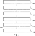
- Fig. 2 shows a flowchart which illustrates a method of operating the medical imaging system 100 of Fig. 1 .
- the static angiographic image 114 is received.
- the static angiographic image is descriptive of a region of interest of a subject.
- the region of interest comprises voxels.
- the static angiographic image may be received in different ways. In some instances the static angiographic image may be received by reconstructing the image from magnetic resonance data. In other instances the static angiographic image may be received via a network connection or other data source.
- step 202 a time series of angiographic images of the region of interest is received.
- the time series of angiographic images may be acquired or received in a variety of ways.
- step 204 the image mask 118 is constructed using the static angiographic image 114.
- the image mask is an identification of voxels within the region of interest.
- step 206 a time dependent signal 120 is determined for each voxel within the image mask using the time series of angiographic images 116.
- step 208 the composite angiographic image 128 is constructed.
- the construction of the composite angiographic image 128 is shown as being performed in sub-steps 210 and 212.
- the fill time 126 is assigned to each of the voxels in the image mask using an extremum of the time dependent signal if the extremum deviates from the average 122 of the time dependent signal 120 more than a predetermined threshold.
- the construction of the composite angiographic image is further performed by identifying voxels within the image mask 118 as being unfilled voxels if the extremum deviates from the average 122 of the time dependent signal less than a predetermined threshold.
- Fig. 3 illustrates a further example of a medical imaging system 300.
- the medical imaging system 300 is shown as comprising a magnetic resonance imaging system 302.
- the magnetic resonance imaging system 302 comprises a magnet 304.
- the magnet 304 is a superconducting cylindrical type magnet 304 with a bore 306 through it. The use of different types of magnets is also possible. Inside the cryostat of the cylindrical magnet, there is a collection of superconducting coils. Within the bore 306 of the cylindrical magnet 304 there is an imaging zone 308 where the magnetic field is strong and uniform enough to perform magnetic resonance imaging.
- the magnetic field gradient coils 310 are connected to a magnetic field gradient coil power supply 312.
- the magnetic field gradient coils 310 are intended to be representative.
- magnetic field gradient coils 310 contain three separate sets of coils for spatially encoding in three orthogonal spatial directions.
- a magnetic field gradient power supply supplies current to the magnetic field gradient coils. The current supplied to the magnetic field gradient coils 310 is controlled as a function of time and may be ramped or pulsed.
- a radio-frequency coil 314 Adjacent to the imaging zone 308 is a radio-frequency coil 314 for manipulating the orientation of magnetic spins within the imaging zone 308 and for receiving radio transmissions from spins also within the imaging zone 308.
- the radio frequency antenna may contain multiple coil elements.
- the radio frequency antenna may also be referred to as a channel or antenna.
- the radio-frequency coil 314 is connected to a radio frequency transceiver 316.
- the radio-frequency coil 314 and radio frequency transceiver 316 may be replaced by separate transmit and receive coils and a separate transmitter and receiver. It is understood that the radio-frequency coil 314 and the radio frequency transceiver 316 are representative.
- the radio-frequency coil 314 is intended to also represent a dedicated transmit antenna and a dedicated receive antenna.
- the transceiver 316 may also represent a separate transmitter and receiver.
- the radio-frequency coil 314 may also have multiple receive/transmit elements and the radio frequency transceiver 316 may have multiple receive/transmit channels.
- the tagging location 324 is a region where a bolus of blood can be labeled either via ASL or TOF magnetic resonance imaging. In this example the tagging location 324 is shown as a plane. This would be used for example for non-selective ASL magnetic resonance imaging. The tagging location 324 could also be localized to a smaller region to perform selective ASL.
- the transceiver 316 and the magnetic field gradient coil power supply 312 are shown as being connected to the hardware interface 104 of computer system 102.
- the computer memory 110 is further shown as containing pulse sequence commands 330.
- Pulse sequence commands as used herein encompass commands or a timing diagram which may be converted into commands which are used to control the functions of the magnetic resonance imaging system 600 as a function of time. Pulse sequence commands are the implementation of the magnetic resonance imaging protocol applied to a particular magnetic resonance imaging system 600.
- the computer memory 110 is further shown as containing TOF magnetic resonance data 332 that was acquired by controlling the magnetic resonance imaging system 302 with the pulse sequence commands 330.
- the memory 110 is further shown as containing ASL magnetic resonance data 334 that was acquired by controlling the magnetic resonance imaging system 302 with the pulse sequence commands 330 also.
- the static angiographic image 114 is a TOF magnetic resonance angiographic image.
- the time series of angiographic images 116 is a time series of arterial spin labeling magnetic resonance angiographic images.
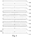
- Fig. 4 shows a flowchart which illustrates a method of operating the medical imaging system 300 of Fig. 3 .
- the method shown in Fig. 4 is similar to that of Fig. 2 with a number of additional steps performed.
- the processor uses the pulse sequence commands to acquire the TOF magnetic resonance data 332.
- the processor 106 uses the pulse sequence commands 330 to control the magnetic resonance imaging system 302 to acquire the ASL magnetic resonance data 334.
- Steps 400 and 402 may be reversed in order and may also be performed at the same time.
- the pulse sequence commands 330 could be an interleaved pulse sequence commands that acquires the portions of the TOF magnetic resonance data 332 and portions of the ASL magnetic resonance data 334 alternatively in time.
- steps 404 and 406 are performed. Steps 404 and 406 may be performed in reverse order.
- step 404 the static angiographic image 114 is provided by reconstructing the static angiographic image from the TOF magnetic resonance data 332.
- step 406 the time series of angiographic images 116 is provided by reconstructing the time series of angiographic images 116 from the ASL magnetic resonance data 334.
- step 406 the method proceeds to step 200 as is illustrated in Fig. 2 .
- Examples may provide a method to generate angiographic images of the arterial vasculature with high spatial and temporal resolution by combining information of both, high-resolved TOF acquisitions and temporal-resolved ASL images.
- the signal of each voxel in both ASL and TOF data is being analyzed simultaneously and conclusions about pathological alterations and technical issues can be drawn. This information can be used to pinpoint the attention of the radiologist to conspicuous features in images in order to avoid overseeing abnormalities, but also to accelerate the diagnostic process.
- a detailed visualization of brain feeding arteries and intracranial vessels may be important for the diagnosis of many cerebral diseases, such as stroke, arterio-venous malformations, aneurysms etc.
- High spatial resolution may be beneficial because it enables the assessment of the structural morphology of vessels, for instance, to measure the intra-luminar diameter in stenotic arteries or to detect small aneurysms.
- additional information about the hemodynamics is required like blood flow velocity, mean transit time etc.
- a combination of image information of different techniques seems attractive to cancel out individual drawbacks while emphasizing the benefits of each technique and thus simplify an evaluation of the data.
- this can also be used to automatically (or semi-automatically) pre-analyze the image information and classify certain properties according to the information of each individual sequence. Mismatches of image information that may point to a pathological process or technical issue can be pinpointed and emphasized for the radiologist.
- Digital subtraction angiography presents the gold standard for angiography regarding spatial and temporal resolution.
- the method only provides projection images of vessels and quantification of hemodynamic parameters is difficult.
- the procedure is invasive and a catheter is being placed in the vessel of interest to administer contrast agent.
- Computed tomography CT is less invasive and can generate 3D images of the vasculature, but - as in DSA - the patient is exposed to ionizing radiation and exogenous contrast agent material.
- Magnetic resonance imaging (MRI) offers a variety of acquisition techniques to visualize vessels.
- Time-of-flight angiography is often used in clinical routine measurements as it can generate angiograms with high spatial resolution, however, no hemodynamic information can be gathered.
- Time-resolved MR methods usually require gadolinium-based contrast agents and only have limited temporal and spatial resolution.
- Arterial Spin Labeling (ASL) techniques can create time-resolved angiograms without the usage of contrast agents, but are also limited in spatial resolution in order to reduce the overall acquisition time which impedes the assessment of small vascular structures.
- the radiologist has to interpret each image series individually and form a complete picture in his mind by gathering all information from the different images. There is no tool available that can analyze the image information and indicate abnormalities prior to the diagnostic process.
- Examples may provide for a method that makes it possible to generate angiographic images of the arterial vasculature with high spatial and temporal resolution by combining information of both, high-resolved TOF acquisitions and temporal-resolved ASL images.
- TOF and ASL images are registered using spatial and temporal information.
- the signal of each voxel in both ASL and TOF data is being analyzed simultaneously. Thereby, each voxel can be classified according to several properties (explained in more detail below). This information can be used to pinpoint the attention of the radiologist to conspicuous features in images in order to avoid overseeing abnormalities, but also to accelerate the diagnostic process.
- Fig. 5 shows an example of a static angiographic image 114 and also shows one frame of a time series of angiographic images 116.
- image 116 is intended to represent an entire time series of angiographic images, although only one image is shown.
- the static angiographic image 114 is a TOF angiographic image that is 512 x 512 voxels and makes up 170 slices.
- the time series of angiographic images 116 is 224 x 224 voxels per slice and has only 120 slices.
- the ASL image 116 therefore has a lower resolution.
- the ASL image is resized into a resized time series angiographic image 116. The image is interpolated such that the resized image 116 now has 512 x 512 voxels per slice and also has 170 slices.
- Fig. 6 shows a view of the static angiographic image 114 and the resized time series of angiographic images 116' from Fig. 5 . It is used to illustrate the determination of the fill time.
- Each of the marked regions indicates a number of voxels.
- Adjacent to the images 114 and 116' are a number of plots that are labeled according to which region they represent. Each plot is a plot of time in terms of frames as a function of voxel signal or intensity 612. Within each plot is then the time dependent signal 120 and also is shown the predetermined threshold 614.
- Region 600 is outside of the mask and shows a noise signal.
- Region 602 shows a voxel or voxels which are filled early.
- Region 604 shows a region which is filled at a medium or middle time.
- Region 606 shows a voxel which is filled comparatively late.
- Box 608 shows a venous signal.
- box 608 is located within the mask and region 600 is not.
- Fig. 6 illustrates the signal evaluation in TOF and ASL images. For instance, this can be used to analyze flow behavior or draw conclusions on the type of artery. Mismatches may indicate pathological alterations of the vessels, but also technical issues (region 608). Detailed description of selected possibilities is given in the text above.
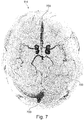
- Fig. 7 shows a further view of image 114.
- Fig. 7 there are three regions which are surrounded by dashed lines and marked 700. These are marked regions 700.
- the marked regions show mismatches in the analysis of the images and when plotted may also be plotted and colored for emphasis. They may indicate pathological alterations of the vessels and/or technical issues during acquisition.
- the visualization of venous vessels appears due to technical issues perhaps for insufficient saturation during acquisition of data.
- the attention of the radiologist can be pinpointed to critical areas and may assist in overall diagnostic process or the adjustment of the acquisition of the images.
- Mismatches in the analysis of the images may be color-coded and can indicate pathological alterations of the vessels and technical issues.
- the marked regions 700 indicate visualizations of venous vessels appeared due to technical issues (insufficient saturation). By this, the attention of the radiologist can be pinpointed to critical areas, supporting the overall diagnostic process.
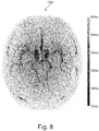
- Fig. 8 shows an example of a composite angiographic image 128 that was constructed using the static angiographic image 114 and the time series of angiographic images 116' from Figs. 5 and 6 .
- the composite angiographic image is a mapped TOF angiographic image with the temporal information from ASL presented as time of arrival map. Since ASL images only present arterial vessels, the presented image analysis can avoid visualization of venous vessels which may appear in QF images due to technical issues such as insufficient saturation as was indicated in Fig. 7 . It is noted that the artifacts illustrated in Fig. 7 are not present in Fig. 8.
- Fig. 7 shows an example of a composite angiographic image 128 that was constructed using the static angiographic image 114 and the time series of angiographic images 116' from Figs. 5 and 6 .
- the composite angiographic image is a mapped TOF angiographic image with the temporal information from ASL presented as time of arrival map. Since A
- FIG. 8 shows a mapped TOF image with the temporal information from ASL presented as a time-of-arrival map. Since ASL images only present arterial vessels, the presented image analysis can avoid the visualization of venous vessels which may appear in TOF images due to technical issues (insufficient saturation). This can be indicated as in Fig. 7 .
- Examples may be applied to such applications as, but are not limited to: imaging cerebrovascular diseases with complex and diffuse flow patterns, for which not only high resolution information about the arteries is important, but also underlying hemodynamic properties. These can be stroke, arterio-venous malformations (AVM), but also fistulas, shunting arteries and tumor feeding arteries. Other applications include stenotic arteries, and occlusions.
- Examples may not necessarily limited to the cerebral vasculature, but might also be used to visualize other arteries. These include visualization of the renal arteries, the coronary arteries, as well as the peripheral lower leg arteries.
- TOF angiography an image slice or volume is being saturated and data is acquired after unsaturated blood has entered the image stack. It is possible, to perform a certain amount of TOF imaging, i.e. a subset of a single slice or image volume, in between ASL sequences that are repeated several times (see Fig. 9 below).
- Fig. 9 illustrates a timing diagram for one implementation of the pulse sequence commands 330.
- the pulse sequence commands acquire the TOF magnetic resonance data and the ASL magnetic resonance data using an interleaved pulse sequence.
- An alternative would be to acquire the complete TOF magnetic resonance data with one pulse sequence and then acquire the ASL magnetic resonance data with the second pulse sequence.
- the interleaved pulse sequence 330 comprises two blocks which alternate. There is a first repetition 900 and a second repetition 902. These two blocks repeat one after the other continuously until all of the data is acquired.
- the first repetition 900 there is an ASL label 902, then an ASL readout is performed 904, and then finally a TOF readout 906.
- an ASL control 908 is performed first.
- an ASL readout 910 is performed followed by a TOF readout 912.
- the ASL readout 904 and 910 have the same phase encoding.
- the TOF readout 906 has a different phase encoding than the TOF readout 912.
- a computer program may be stored/distributed on a suitable medium, such as an optical storage medium or a solid-state medium supplied together with or as part of other hardware, but may also be distributed in other forms, such as via the Internet or other wired or wireless telecommunication systems. Any reference signs in the claims should not be construed as limiting the scope.
Landscapes
- Physics & Mathematics (AREA)
- Engineering & Computer Science (AREA)
- General Physics & Mathematics (AREA)
- Nuclear Medicine, Radiotherapy & Molecular Imaging (AREA)
- Health & Medical Sciences (AREA)
- Theoretical Computer Science (AREA)
- Radiology & Medical Imaging (AREA)
- General Health & Medical Sciences (AREA)
- High Energy & Nuclear Physics (AREA)
- Condensed Matter Physics & Semiconductors (AREA)
- Computer Vision & Pattern Recognition (AREA)
- Signal Processing (AREA)
- Artificial Intelligence (AREA)
- Pulmonology (AREA)
- Pathology (AREA)
- Medical Informatics (AREA)
- Quality & Reliability (AREA)
- Computer Graphics (AREA)
- Vascular Medicine (AREA)
- Magnetic Resonance Imaging Apparatus (AREA)
- Apparatus For Radiation Diagnosis (AREA)
- Image Processing (AREA)
Priority Applications (6)
| Application Number | Priority Date | Filing Date | Title |
|---|---|---|---|
| EP17204271.5A EP3493151A1 (de) | 2017-11-29 | 2017-11-29 | Kombination von zeitlich aufgelösten angiographischen bildern mit einem räumlichen aufgelösten angiographischen bild |
| JP2020528941A JP7252230B2 (ja) | 2017-11-29 | 2018-11-29 | 時間分解血管造影画像と空間分解血管造影画像との組み合わせ |
| CN201880077563.7A CN111417979B (zh) | 2017-11-29 | 2018-11-29 | 时间分辨的血管造影图像与空间分辨血管造影图像的组合 |
| US16/767,613 US11410353B2 (en) | 2017-11-29 | 2018-11-29 | Combination of temporally resolved angiographic images with a spatially resolved angiographic image |
| EP18807386.0A EP3718076B1 (de) | 2017-11-29 | 2018-11-29 | Kombination von zeitlich aufgelösten angiographischen bildern mit einem räumlichen aufgelösten angiographischen bild |
| PCT/EP2018/083060 WO2019106113A1 (en) | 2017-11-29 | 2018-11-29 | Combination of temporally resolved angiographic images with a spatially resolved angiographic image |
Applications Claiming Priority (1)
| Application Number | Priority Date | Filing Date | Title |
|---|---|---|---|
| EP17204271.5A EP3493151A1 (de) | 2017-11-29 | 2017-11-29 | Kombination von zeitlich aufgelösten angiographischen bildern mit einem räumlichen aufgelösten angiographischen bild |
Publications (1)
| Publication Number | Publication Date |
|---|---|
| EP3493151A1 true EP3493151A1 (de) | 2019-06-05 |
Family
ID=60515180
Family Applications (2)
| Application Number | Title | Priority Date | Filing Date |
|---|---|---|---|
| EP17204271.5A Withdrawn EP3493151A1 (de) | 2017-11-29 | 2017-11-29 | Kombination von zeitlich aufgelösten angiographischen bildern mit einem räumlichen aufgelösten angiographischen bild |
| EP18807386.0A Active EP3718076B1 (de) | 2017-11-29 | 2018-11-29 | Kombination von zeitlich aufgelösten angiographischen bildern mit einem räumlichen aufgelösten angiographischen bild |
Family Applications After (1)
| Application Number | Title | Priority Date | Filing Date |
|---|---|---|---|
| EP18807386.0A Active EP3718076B1 (de) | 2017-11-29 | 2018-11-29 | Kombination von zeitlich aufgelösten angiographischen bildern mit einem räumlichen aufgelösten angiographischen bild |
Country Status (5)
| Country | Link |
|---|---|
| US (1) | US11410353B2 (de) |
| EP (2) | EP3493151A1 (de) |
| JP (1) | JP7252230B2 (de) |
| CN (1) | CN111417979B (de) |
| WO (1) | WO2019106113A1 (de) |
Cited By (4)
| Publication number | Priority date | Publication date | Assignee | Title |
|---|---|---|---|---|
| CN111062997A (zh) * | 2019-12-09 | 2020-04-24 | 上海联影医疗科技有限公司 | 一种血管造影成像方法、系统、设备和存储介质 |
| CN111599004A (zh) * | 2020-05-18 | 2020-08-28 | 复旦大学附属中山医院 | 一种3d血管成像系统、方法及装置 |
| WO2021201753A1 (en) * | 2020-03-28 | 2021-10-07 | Oezarslan Evren | A magnetic resonance method, software product, and system for determining a diffusion propagator or related diffusion parameters for spin-labelled particles |
| EP4362042A1 (de) * | 2022-10-31 | 2024-05-01 | Siemens Healthineers AG | Schätzung der pharmakokinetik eines kontrastmittels durch ein analytisches modell eines kardiovaskulären systems und/oder einen algorithmus eines neuronalen netzwerks |
Families Citing this family (7)
| Publication number | Priority date | Publication date | Assignee | Title |
|---|---|---|---|---|
| US11430087B2 (en) * | 2019-12-20 | 2022-08-30 | Zoox, Inc. | Using maps comprising covariances in multi-resolution voxels |
| US11288861B2 (en) | 2019-12-20 | 2022-03-29 | Zoox, Inc. | Maps comprising covariances in multi-resolution voxels |
| DE102020200013A1 (de) * | 2020-01-03 | 2021-07-08 | Siemens Healthcare Gmbh | Magnetresonanzeinrichtung und Verfahren zum Betrieb einer Magnetresonanzeinrichtung, Computerprogramm und elektronisch lesbarer Datenträger |
| KR102283673B1 (ko) * | 2020-11-30 | 2021-08-03 | 주식회사 코어라인소프트 | 병변 추적 검사에 기반하여 진단 보조 정보의 임계치를 조정하는 의료 영상 판독 지원 장치 및 방법 |
| CN113593678B (zh) * | 2021-08-03 | 2022-06-10 | 北京安德医智科技有限公司 | 基于血管影像补全的脑卒中分型方法及装置 |
| EP4152032A1 (de) * | 2021-09-17 | 2023-03-22 | Koninklijke Philips N.V. | Bestimmung einer subjektspezifischen hämodynamischen antwortfunktion |
| CN115514962B (zh) * | 2022-11-22 | 2023-03-24 | 深圳市亿康医疗技术有限公司 | 一种心血管造影图像的图像压缩方法 |
Family Cites Families (16)
| Publication number | Priority date | Publication date | Assignee | Title |
|---|---|---|---|---|
| US5590654A (en) * | 1993-06-07 | 1997-01-07 | Prince; Martin R. | Method and apparatus for magnetic resonance imaging of arteries using a magnetic resonance contrast agent |
| JP2003299646A (ja) * | 2002-04-11 | 2003-10-21 | Hitachi Medical Corp | 画像解析装置 |
| JP5591440B2 (ja) * | 2007-01-17 | 2014-09-17 | 株式会社東芝 | 医用画像表示装置 |
| KR20140033332A (ko) * | 2010-12-17 | 2014-03-18 | 오르후스 우니베르시테트 | 조직 병변의 묘사방법 |
| EP2699928B1 (de) * | 2011-04-21 | 2016-08-24 | Koninklijke Philips N.V. | Robuste gleichzeitige magnetresonanzangiographie ohne kontrastmittel und magnetresonanzabbildung von blutungen in arteriosklerotischen plaques (rsnap) mithilfe von fluss-markierung |
| DE102011083674A1 (de) * | 2011-09-29 | 2013-04-04 | Siemens Aktiengesellschaft | Angiographisches Untersuchungsverfahren zur Darstellung von Flusseigenschaften |
| JP5919717B2 (ja) * | 2011-10-07 | 2016-05-18 | コニカミノルタ株式会社 | 動態医用画像生成システム |
| US9712738B2 (en) * | 2012-04-17 | 2017-07-18 | E-Vision Smart Optics, Inc. | Systems, devices, and methods for managing camera focus |
| JP6351942B2 (ja) * | 2012-08-31 | 2018-07-04 | キヤノンメディカルシステムズ株式会社 | 医用診断画像処理装置 |
| JP6351323B2 (ja) * | 2014-03-20 | 2018-07-04 | オリンパス株式会社 | 画像処理装置、画像処理方法、及び画像処理プログラム |
| US9702956B2 (en) * | 2014-03-25 | 2017-07-11 | Beth Israel Deaconess Medical Center, Inc. (Bidmc, Inc.) | MRI methods and apparatus for flexible visualization of any subset of an enlarged temporal window |
| WO2015158879A1 (en) * | 2014-04-18 | 2015-10-22 | Koninklijke Philips N.V. | Mri involving the acquisition of an angiography weighted image and of a perfusion weighted image |
| US20160135775A1 (en) * | 2014-11-17 | 2016-05-19 | Wisconsin Alumni Research Foundation | System And Method For Time-Resolved, Three-Dimensional Angiography With Physiological Information |
| US11089970B2 (en) * | 2015-06-12 | 2021-08-17 | Koninklijke Philips N.V. | Imaging fluid flow into a region of interest |
| DE102016205507A1 (de) * | 2016-04-04 | 2017-10-05 | Siemens Healthcare Gmbh | Verfahren zur Ermittlung einer den Blutfluss in Kollateralen beschreibenden Kollateralinformationen, medizinische Bildaufnahmeeinrichtung, Computerprogramm und elektronisch lesbarer Datenträger |
| EP3446141A1 (de) * | 2016-04-21 | 2019-02-27 | Koninklijke Philips N.V. | Magnetresonanzbildgebung von arteriellen strukturen |
-
2017
- 2017-11-29 EP EP17204271.5A patent/EP3493151A1/de not_active Withdrawn
-
2018
- 2018-11-29 WO PCT/EP2018/083060 patent/WO2019106113A1/en unknown
- 2018-11-29 JP JP2020528941A patent/JP7252230B2/ja active Active
- 2018-11-29 CN CN201880077563.7A patent/CN111417979B/zh active Active
- 2018-11-29 EP EP18807386.0A patent/EP3718076B1/de active Active
- 2018-11-29 US US16/767,613 patent/US11410353B2/en active Active
Non-Patent Citations (4)
| Title |
|---|
| BERNSTEIN: "Handbook of MRI Pulse Sequences", 2004, ELSEVIER, article "Handbook of MRI Pulse Sequences", pages: 802 through 829 |
| JENSEN-KONDERING ULF ET AL: "Superselective pseudo-continuous arterial spin labeling angiography", EUROPEAN JOURNAL OF RADIOLOGY, ELSEVIER SCIENCE, NL, vol. 84, no. 9, 22 June 2015 (2015-06-22), pages 1758 - 1767, XP029260120, ISSN: 0720-048X, DOI: 10.1016/J.EJRAD.2015.05.034 * |
| MAZAHERI YOUSEF ET AL: "Combined time-resolved and high-spatial-resolution 3D MRA using an extended adaptive acquisition", JOURNAL OF MAGNETIC RESONANCE IMAGING, SOCIETY FOR MAGNETIC RESONANCE IMAGING, OAK BROOK, IL, US, vol. 15, no. 3, 1 March 2002 (2002-03-01), pages 291 - 301, XP002302804, ISSN: 1053-1807 * |
| NILS DANIEL FORKERT ET AL: "4D blood flow visualization fusing 3D and 4D MRA image sequences", JOURNAL OF MAGNETIC RESONANCE IMAGING, vol. 36, no. 2, 1 August 2012 (2012-08-01), US, pages 443 - 453, XP055437927, ISSN: 1053-1807, DOI: 10.1002/jmri.23652 * |
Cited By (7)
| Publication number | Priority date | Publication date | Assignee | Title |
|---|---|---|---|---|
| CN111062997A (zh) * | 2019-12-09 | 2020-04-24 | 上海联影医疗科技有限公司 | 一种血管造影成像方法、系统、设备和存储介质 |
| CN111062997B (zh) * | 2019-12-09 | 2023-09-12 | 上海联影医疗科技股份有限公司 | 一种血管造影成像方法、系统、设备和存储介质 |
| WO2021201753A1 (en) * | 2020-03-28 | 2021-10-07 | Oezarslan Evren | A magnetic resonance method, software product, and system for determining a diffusion propagator or related diffusion parameters for spin-labelled particles |
| US11789106B2 (en) | 2020-03-28 | 2023-10-17 | Kalmia Ab | Magnetic resonance method, software product, and system for determining a diffusion propagator or related diffusion parameters for spin-labelled particles |
| CN111599004A (zh) * | 2020-05-18 | 2020-08-28 | 复旦大学附属中山医院 | 一种3d血管成像系统、方法及装置 |
| CN111599004B (zh) * | 2020-05-18 | 2023-09-12 | 复旦大学附属中山医院 | 一种3d血管成像系统、方法及装置 |
| EP4362042A1 (de) * | 2022-10-31 | 2024-05-01 | Siemens Healthineers AG | Schätzung der pharmakokinetik eines kontrastmittels durch ein analytisches modell eines kardiovaskulären systems und/oder einen algorithmus eines neuronalen netzwerks |
Also Published As
| Publication number | Publication date |
|---|---|
| JP2021504035A (ja) | 2021-02-15 |
| EP3718076B1 (de) | 2021-04-28 |
| CN111417979B (zh) | 2024-05-14 |
| WO2019106113A1 (en) | 2019-06-06 |
| US20200294286A1 (en) | 2020-09-17 |
| US11410353B2 (en) | 2022-08-09 |
| CN111417979A (zh) | 2020-07-14 |
| EP3718076A1 (de) | 2020-10-07 |
| JP7252230B2 (ja) | 2023-04-04 |
Similar Documents
| Publication | Publication Date | Title |
|---|---|---|
| US11410353B2 (en) | Combination of temporally resolved angiographic images with a spatially resolved angiographic image | |
| US10823798B2 (en) | Virtual CT images from magnetic resonance images | |
| US10677871B2 (en) | Magnetic resonance imaging of arterial structures | |
| EP3602097B1 (de) | Auswahl von magnetresonanzfingerabdruckwörterbüchern für anatomische bereiche | |
| JP2019506916A (ja) | 磁気共鳴拡散画像化のための方法及び装置 | |
| US11089970B2 (en) | Imaging fluid flow into a region of interest | |
| EP3523669B1 (de) | Kombinierte arterielle spin-markierung und magnetresonanzfingerabdruckerzeugung | |
| US10684341B2 (en) | Magnetic resonance imaging of arterial structures | |
| EP3607527B1 (de) | Quantitative bewertung von zeitveränderlichen daten | |
| EP4321890A1 (de) | Bestimmung von rekonstruktionsparametern für die rekonstruktion von synthetischen magnetresonanzbildern | |
| EP3996036A1 (de) | Magnetresonanzangiographie mit t2-gewichteten bildern | |
| EP3581090A1 (de) | Tomographische abbildung elektrischer eigenschaften von leitfähigkeitsveränderungen | |
| US20220012876A1 (en) | Determination of a further processing location in magnetic resonance imaging | |
| EP4127754A1 (de) | Magnetresonanzbildgebung von mikroverkalkungen der brust |
Legal Events
| Date | Code | Title | Description |
|---|---|---|---|
| PUAI | Public reference made under article 153(3) epc to a published international application that has entered the european phase |
Free format text: ORIGINAL CODE: 0009012 |
|
| AK | Designated contracting states |
Kind code of ref document: A1 Designated state(s): AL AT BE BG CH CY CZ DE DK EE ES FI FR GB GR HR HU IE IS IT LI LT LU LV MC MK MT NL NO PL PT RO RS SE SI SK SM TR |
|
| AX | Request for extension of the european patent |
Extension state: BA ME |
|
| RAP1 | Party data changed (applicant data changed or rights of an application transferred) |
Owner name: KONINKLIJKE PHILIPS N.V. |
|
| STAA | Information on the status of an ep patent application or granted ep patent |
Free format text: STATUS: THE APPLICATION IS DEEMED TO BE WITHDRAWN |
|
| 18D | Application deemed to be withdrawn |
Effective date: 20191206 |