EP3492957A1 - Reinforcement structure - Google Patents
Reinforcement structure Download PDFInfo
- Publication number
- EP3492957A1 EP3492957A1 EP17836593.8A EP17836593A EP3492957A1 EP 3492957 A1 EP3492957 A1 EP 3492957A1 EP 17836593 A EP17836593 A EP 17836593A EP 3492957 A1 EP3492957 A1 EP 3492957A1
- Authority
- EP
- European Patent Office
- Prior art keywords
- tension
- reinforcement structure
- resistance member
- heat
- optical fibers
- Prior art date
- Legal status (The legal status is an assumption and is not a legal conclusion. Google has not performed a legal analysis and makes no representation as to the accuracy of the status listed.)
- Ceased
Links
Images



Classifications
-
- G—PHYSICS
- G02—OPTICS
- G02B—OPTICAL ELEMENTS, SYSTEMS OR APPARATUS
- G02B6/00—Light guides; Structural details of arrangements comprising light guides and other optical elements, e.g. couplings
- G02B6/24—Coupling light guides
- G02B6/255—Splicing of light guides, e.g. by fusion or bonding
- G02B6/2558—Reinforcement of splice joint
Definitions
- the present invention relates to a reinforcement structure for reinforcing a fusion splice point of an optical fiber.
- Fiber lasers and other such fiber-optic systems that include a plurality optical fibers whose end faces have been fusion-spliced are used widely.
- Such fiber-optic systems often include a reinforcement structure for reinforcing the fusion splice point.
- a typical example of a reinforcement structure for reinforcing a fusion splice point of an optical fiber is a configuration in which an optical fiber and a tension-resistance member are bundled together by a heat-shrinkable tube.
- a reinforcement structure is disclosed in, for example, Patent Literatures 1 and 2.
- An object of the present invention is to provide a reinforcement structure which (i) has a simple configuration in which an optical fiber and a tension-resistance member are bundled by use of a heat-shrinkable tube, and (ii) decreases the likelihood of degradation of the heat-shrinkable tube.
- a reinforcement structure in accordance with an aspect of the present invention is a reinforcement structure for reinforcing a fusion splice point at which a plurality of optical fibers are fusion-spliced, the reinforcement structure including: a tension-resistance member; a heat-shrinkable tube which bundles the plurality of optical fibers and the tension-resistance member; and a radiator which is in thermal contact with the tension-resistance member, the tension-resistance member having a flat surface which faces respective circumferential surfaces of the plurality of optical fibers.
- An embodiment of the present invention makes it possible provide a reinforcement structure which (i) makes it possible to reinforce an optical fiber in a simple manner and (ii) decreases the likelihood of degradation of a heat-shrinkable tube.
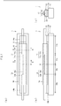
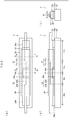
- Fig. 1 is a top view of the reinforcement structure 1.
- Fig. 1 is a right side view of the reinforcement structure 1.
- Fig. 1 is a front view of the reinforcement structure 1.
- Fig. 2 is a cross-sectional view of the reinforcement structure 1, taken along line A-A.
- Fig. 2 is another cross-sectional view of the reinforcement structure 1, taken along line B-B.
- the reinforcement structure 1 is a structure for reinforcing a fusion splice point P at which an optical fiber 11 and an optical fiber 12 are fusion-spliced.
- the reinforcement structure 1 includes a tension-resistance member 13, a leg part 14a, a leg part 14b, a radiator 15, a heat-shrinkable tube 16, and a low-refractive-index resin 17.
- the optical fiber 11 includes (i) a bare fiber part 11a made of glass and (ii) a jacket 11b which is made of resin and covers a circumferential surface of the bare fiber part 11a.
- the jacket 11b has been removed in a section (hereinafter, "jacket-removed section") I1a including the fusion splice point P.
- the optical fiber 12 includes (i) a bare fiber part 12a made of glass and (ii) a jacket 12b which is made of resin and covers a circumferential surface of the bare fiber part 12a.
- the jacket 12b has been removed in a section (hereinafter, "jacket-removed section”) I2a including the fusion splice point P.
- the tension-resistance member 13 has a flat surface and is provided so that the flat surface faces the circumferential surfaces of the optical fibers 11 and 12 at least in the jacket-removed sections I1a and I2a.
- the tension-resistance member 13 is a plate-like member which is provided such that an upper surface of the plate-like member faces the circumferential surfaces of the optical fibers 11 and 12 in (i) the jacket-removed sections I1a and I2a and (ii) adjacent sections I1b and I2b, which are adjacent to the jacket-removed sections I1a and I2a, respectively.
- the upper surface of the tension-resistance member 13 has a width which is greater than the diameter of the optical fibers 11 and 12.
- a material to be used for the tension-resistance member 13 need only have a high elastic modulus (at least higher than the elastic modulus of the bare fiber parts 11a and 12a) and a high thermal conductivity.
- suitable materials for the tension-resistance member 13 include copper, copper molybdenum, and other metals.
- the leg part 14a is provided to a front end of a lower surface of the tension-resistance member 13.
- the leg part 14b is provided to a rear end of the lower surface of the tension-resistance member 13.
- the tension-resistance member 13 is in thermal contact with the radiator 15 (described later) via the leg parts 14a and 14b.
- the leg parts 14a and 14b may be members separate from the tension-resistance member 13 which have been bonded to the tension-resistance member 13, or may be members which are a part of the tension-resistance member 13 and have been provided integrally with tension-resistance member 13.
- the leg parts 14a and 14b are each a member which (i) has a rectangular parallelepiped shape, (ii) has a height greater than a thickness of the heat-shrinkable tube 16, and (iii) has been bonded to the front end or rear end of the lower surface of the tension-resistance member 13.
- a material to be used for the leg parts 14a and 14b need only have a thermal conductivity which is approximately equal to that of the tension-resistance member 13. Examples of suitable materials for the leg parts 14a and 14b include copper, copper molybdenum, and other metals.
- the radiator 15 is a member for externally dissipating heat, specifically heat which has been conducted from the tension-resistance member 13 via the leg parts 14a and 14b.
- a known water-cooled plate is used as the radiator 15.
- a known air-cooled plate may be used as the radiator 15.
- the heat-shrinkable tube 16 is a tubular member which bundles the optical fibers 11 and 12 and the tension-resistance member 13.
- a material to be used for the heat-shrinkable tube 16 need only be heat-shrinkable.
- suitable materials for the heat-shrinkable tube 16 include a fluorocarbon resin such as (poly)tetrafluoroethylene (PTEF) and an olefin resin such as polyethylene (PE). Because the tension-resistance member 13 has a width which is greater than the diameter of the optical fibers 11 and 12, the heat-shrinkable tube 16 after being shrunk takes on a contour which is mountain-like when viewed in a cross section, as illustrated in (c) of Fig. 1 , and in (a) and (b) of Fig. 2 .
- an inner circumferential surface of the heat-shrinkable tube 16 is in close contact with (i) the lower surface and side surfaces of the tension-resistance member 13 and (ii) respective upper portions of the circumferential surfaces of the optical fibers 11 and 12 (outer circumferential surface of the jacket 11b), as illustrated in (a) of Fig. 2 .
- two small gaps are formed to the left and right of the optical fibers 11 and 12. The small gaps are surrounded by the circumferential surfaces of the optical fibers 11 and 12, the upper surface of the tension-resistance member 13, and the inner circumferential surface of the heat-shrinkable tube 16.
- the inner circumferential surface of the heat-shrinkable tube 16 is in close contact with the lower surface and side surfaces of the tension-resistance member 13, as illustrated in (b) of Fig. 2 . Furthermore, in the jacket-removed sections I1a and I2a, a large gap surrounding the optical fibers 11 and 12 is formed. The large gap is surrounded by the upper surface of the tension-resistance member 13 and the inner circumferential surface of the heat-shrinkable tube 16.
- the large gap and the small gaps are filled with the low-refractive-index resin 17, which has a refractive index that is lower than that of cladding (outermost shells of the bare fiber parts 11a and 12a) of the optical fibers 11 and 12.
- a material for the low-refractive-index resin 17 need only (i) have a refractive index which is lower than the refractive index of the cladding of the optical fibers 11 and 12 and (ii) be a thermoplastic resin which softens at a temperature at which the heat-shrinkable tube 16 shrinks, and hardens at normal temperature.
- suitable materials for the low-refractive-index resin 17 include ethylene-vinyl acetate (EVA)
- the reinforcement structure 1 is configured so that the heat-shrinkable tube 16 bundles the optical fibers 11 and 12 and the tension-resistance member 13. This makes it possible to reinforce the optical fibers 11 and 12 in a simple manner.
- the reinforcement structure 1 is configured such that (i) the upper surface of the tension-resistance member 13 faces the circumferential surfaces of the optical fibers 11 and 12 and (ii) the tension-resistance member 13 is in thermal contact with the radiator 15 via the leg parts 14a and 14b.
- the reinforcement structure 1 is configured such that (i) the upper surface of the tension-resistance member 13 faces the circumferential surfaces of the optical fibers 11 and 12 and (ii) the tension-resistance member 13 is in thermal contact with the radiator 15 via the leg parts 14a and 14b.
- the reinforcement structure 1 is configured such that the heat-shrinkable tube 16 is filled with the low-refractive-index resin 17, which has a refractive index that is lower than the refractive index of the cladding of the optical fibers 11 and 12. This makes it possible to decrease the amount of light which leaks from circumferential surfaces of the optical fibers 11 and 12 in the heat-shrinkable tube 16. It is therefore possible to further decrease the likelihood of degradation of the heat-shrinkable tube 16 caused by light which leaks from the circumferential surfaces of the optical fibers 11 and 12 and heats the heat-shrinkable tube 16.
- the reinforcement structure 1 includes the tension-resistance member 13, which is a plate-like member having a rectangular cross section.
- the tension-resistance member 13 is a rod-like member having a circular cross section.
- this makes it possible to reduce, out of light which leaks from the circumferential surfaces of the optical fibers 11 and 12, a proportion of light which is incident upon the heat-shrinkable tube 16. It is therefore possible to further decrease the likelihood of degradation of the heat-shrinkable tube 16 caused by light which leaks from the circumferential surfaces of the optical fibers 11 and 12 and heats the heat-shrinkable tube 16.
- Fig. 3 is a cross-sectional view of an adjacent section of a reinforcement structure in accordance with the comparative example.
- (b) of Fig. 3 is a cross-sectional view of a jacket-removed section of the reinforcement structure in accordance with the comparative example.
- the reinforcement structure in accordance with the comparative example includes a tension-resistance member which is rod-like and has a circular cross section.
- the reinforcement structure 1 in accordance with the present embodiment makes it possible, without excessively increasing the thickness of the reinforcement structure 1, to decrease, out of the light which leaks from the circumferential surfaces of the optical fibers 11 and 12, the proportion of light which is incident upon the heat-shrinkable tube 16.
- the reinforcement structure 1 can be produced by, for example, carried out the following steps in the following order.
- the optical fiber 11 is passed through a resin tube 17, and the resin tube 17 and tension-resistance member 13 are passed through the heat-shrinkable tube 16.
- the resin tube 17 is a tubular member made from a thermoplastic resin and serves as a base material for the low-refractive-index resin 17.
- Fusion splicing step An end face of the optical fiber 11 is fusion-spliced to an end face of the optical fiber 12.
- Heating step Next, the heat-shrinkable tube 16 and the resin tube 17 are heated. This shrinks the heat-shrinkable tube 16 and softens the resin tube 17. As a result, in the adjacent sections I1b and I2b, the inner circumferential surface of the heat-shrinkable tube 16 comes into close contact with (i) the lower surface and side surfaces of the tension-resistance member 13 and (ii) respective upper portions of the circumferential surfaces of the optical fibers 11 and 12 (the outer circumferential surface of the jacket 11b). In the adjacent sections I1b and I2b, the resin tube 17 which has softened becomes the low-refractive-index resin 17 which fills the small gaps to the left and right of the optical fibers 11 and 12.
- Cooling step The heat-shrinkable tube 16 and the low-refractive-index resin 17 are cooled (for example, by natural cooling). This causes the low-refractive-index resin 17 to harden.
- a method of producing the reinforcement structure 1 is not limited to such an example. That is, it is possible to produce the reinforcement structure 1 using a method in which the passing through step is carried out after the fusion splicing step.
- a step of bonding the upper surfaces of the leg parts 14a and 14b to the lower surface of the tension-resistance member 13 may be carried out before the passing through step.
- Fig. 5 is a top view of the reinforcement structure 2.
- Fig. 5 is a right side view of the reinforcement structure 2.
- Fig. 5 is a front view of the reinforcement structure 2.
- Fig. 6 is a cross-sectional view of the reinforcement structure 2, taken along line A-A.
- Fig. 6 is another cross-sectional view of the reinforcement structure 2, taken along line B-B.
- the reinforcement structure 2 in accordance with the present embodiment is a structure for reinforcing a fusion splice point P at which an optical fiber 21 and an optical fiber 22 are fusion-spliced.
- the reinforcement structure 2 includes a tension-resistance member 23, a leg part 24a, a leg part 24b, a leg part 24c, a radiator 25, a heat-shrinkable tube 26, and a low-refractive-index resin 27.
- the tension-resistance member 23, the leg parts 24a and 24b, the radiator 25, the heat-shrinkable tube 26, and the low-refractive-index resin 27 of the reinforcement structure 2 of the present embodiment respectively correspond to the tension-resistance member 13, the leg parts 14a and 14b, the radiator 15, the heat-shrinkable tube 16, and the low-refractive-index resin 17 of the reinforcement structure 1 of Embodiment 1.
- the reinforcement structure 2 of the present embodiment differs from the reinforcement structure 1 of Embodiment 1 in that (i) the leg part 24c is provided to the center of a lower surface of the tension-resistance member 23 and (ii) the heat-shrinkable tube 26 includes a cutout portion 26a through which the leg part 24c is to be passed.
- the tension-resistance member 23 is in thermal contact with the radiator 25 via the leg part 24a, the leg part 24b, and the leg part 24c.
- an amount of heat generated in the tension-resistance member 23 is, relatively, larger in a central portion which overlaps with the fusion splice point P, and smaller at both ends of the tension-resistance member 23.
- the tension-resistance member 23 is in thermal contact with the radiator 25 not only at both ends of the tension-resistance member 23, where the amount of heat generated is relatively small, but also at a central portion of the tension-resistance member 23, where the amount of heat generated is relatively large.
- this configuration enables even more efficient external dissipation of heat generated in the tension-resistance member 23.
- Fig. 7 is a top view of the reinforcement structure 3.
- Fig. 7 is a right side view of the reinforcement structure 3.
- Fig. 7 is a front view of the reinforcement structure 3.
- Fig. 8 is a cross-sectional view of the reinforcement structure 3, taken along line A-A.
- Fig. 8 is another cross-sectional view of the reinforcement structure 3, taken along line B-B.
- the reinforcement structure 3 in accordance with the present embodiment is a structure for reinforcing a fusion splice point P at which an optical fiber 31 and an optical fiber 32 are fusion-spliced.
- the reinforcement structure 3 includes a tension-resistance member 33, a leg part 34a, a leg part 34b, a radiator 35, a heat-shrinkable tube 36, and a low-refractive-index resin 37.
- the tension-resistance member 33, the leg parts 34a and 34b, the radiator 35, the heat-shrinkable tube 36, and the low-refractive-index resin 37 of the reinforcement structure 3 of the present embodiment respectively correspond to the tension-resistance member 13, the leg parts 14a and 14b, the radiator 15, the heat-shrinkable tube 16, and the low-refractive-index resin 17 of the reinforcement structure 1 of Embodiment 1.
- the reinforcement structure 3 of the present embodiment differs from the reinforcement structure 1 of Embodiment 1 in that (i) U-shaped grooves 33a and 33b for holding the optical fibers 31 and 32 are formed outside the jacket-removed sections Ia1 and Ia2 and (ii) in the jacket-removed sections I1a and I2a, the optical fibers 31 and 32 are in contact with an upper surface of the tension-resistance member 33.
- the optical fibers 31 and 32 have been brought closer to the upper surface of the tension-resistance member 33. This makes is possible to decrease, out of light which leaks from the circumferential surfaces of the optical fibers 31 and 32, a proportion of light which is incident upon the heat-shrinkable tube 36. It is therefore possible to decrease the likelihood of degradation of the heat-shrinkable tube 36 caused by light which leaks from the circumferential surfaces of the optical fibers 31 and 32 and heats the heat-shrinkable tube 36.
- the optical fibers 31 and 32 are in contact with the upper surface of the tension-resistance member 33 in the jacket-removed sections I1a and I2a, it is possible to prevent the optical fibers 31 and 32 from bending in a vertical direction. This makes it possible to prevent an increase in damage which could be caused by bending of the optical fibers 31 and 32.
- a reinforcement structure in accordance with an aspect of the present invention is a reinforcement structure for reinforcing a fusion splice point at which a plurality of optical fibers are fusion-spliced, the reinforcement structure including: a tension-resistance member; a heat-shrinkable tube which bundles the plurality of optical fibers and the tension-resistance member; and a radiator which is in thermal contact with the tension-resistance member, the tension-resistance member having a flat surface which faces respective circumferential surfaces of the plurality of optical fibers.
- the optical fiber and the tension-resistance member are bundled together by the heat-shrinkable tube.
- This makes it possible to reinforce the optical fiber in a simple manner.
- the tension-resistance member has a flat surface facing the circumferential surface of the optical fiber and is in thermal contact with the radiator. As such, even if light leaks from the circumferential surface of the optical fiber in the heat-shrinkable tube, a large portion of the leaked light is converted into heat in the tension-resistance member, and a large portion of that heat is dissipated via the radiator. It is therefore possible to decrease the likelihood of degradation of the optical fiber caused by light which leaks from the circumferential surface of the optical fiber and heats the optical fiber.
- the reinforcement structure in accordance with an embodiment of the present invention is preferably configured such that the heat-shrinkable tube is filled with a low-refractive-index resin whose refractive index is lower than a refractive index of cladding of each of the plurality of optical fibers.
- the heat-shrinkable tube is filled with a low-refractive-index resin whose refractive index in lower than a refractive index of cladding of the optical fiber. This makes it possible to decrease the amount of light which leaks from the circumferential surface of the optical fiber in the heat-shrinkable tube. It is therefore possible to further decrease the likelihood of degradation of the optical fiber caused by light which leaks from the circumferential surface of the optical fiber and heats the optical fiber.
- the reinforcement structure in accordance with an embodiment of the present invention is preferably configured such that the tension-resistance member is a plate-like member whose upper surface faces the respective circumferential surfaces of the plurality of optical fibers.
- the above configuration makes it possible, without excessively increasing the thickness of the reinforcement structure, to decrease, out of the light which leaks from the circumferential surface of the optical fiber, the proportion of light which is incident upon the heat-shrinkable tube. It is therefore possible to further decrease the likelihood of degradation of the heat-shrinkable tube caused by light which leaks from the circumferential surface of the optical fiber and heats the heat-shrinkable tube.
- the reinforcement structure in accordance with an embodiment of the present invention is preferably configured such that the flat surface of the tension-resistance member has a width which is greater than a diameter of each of the plurality of optical fibers.
- the above configuration makes it possible to further decrease, out of the light which leaks from the circumferential surface of the optical fiber, the proportion of light which is incident upon the heat-shrinkable tube. It is therefore possible to further decrease the likelihood of degradation of the heat-shrinkable tube caused by light which leaks from the circumferential surface of the optical fiber and heats the heat-shrinkable tube.
- the reinforcement structure in accordance with an embodiment of the present invention is preferably configured such that: the heat-shrinkable tube includes a cutout portion; and the tension-resistance member is in thermal contact with the radiator via a leg part which (i) is provided to a lower surface of the tension-resistance member in a region in which the tension-resistance member faces the fusion splice point and (ii) passes through the cutout portion.
- the above configuration makes it possible to bring the tension-resistance member into thermal contact with the radiator via the leg part in a region in which the tension-resistance member faces the fusion splice point, i.e., a region of the tension-resistance member in which an amount of generated heat is relatively large. This makes it possible to more efficiently dissipate heat generated in the tension-resistance member.
- the reinforcement structure in accordance with an embodiment of the present invention is preferably configured such that a groove for holding the plurality of optical fibers is formed in the upper surface of the tension-resistance member outside a jacket-removed section, such that in the jacket-removed section, the respective circumferential surfaces of the plurality of optical fibers are in contact with the upper surface of the tension-resistance member.
- the optical fiber has been brought closer to the upper surface of the tension-resistance member. This makes is possible to decrease, out of light which leaks from the circumferential surface of the optical fiber, a proportion of light which is incident upon the heat-shrinkable tube. It is therefore possible to decrease the likelihood of degradation of the heat-shrinkable tube caused by light which leaks from the circumferential surface of the optical fiber and heats the heat-shrinkable tube. Furthermore, with the above configuration, because the optical fiber is in contact with the upper surface of the tension-resistance member in the jacket-removed section, it is possible to prevent the optical fiber from bending in a vertical direction. This makes it possible to prevent an increase in damage which could be caused by bending of the optical fiber.
- the reinforcement structure in accordance with an embodiment of the present invention is preferably configured such that the radiator is a water-cooled plate.
- the above configuration makes it possible to more efficiently dissipate heat generated in the tension-resistance member.
- the present invention is not limited to the foregoing embodiments (examples), but can be altered by a skilled person in the art within the scope of the claims.
- the present invention also encompasses, in its technical scope, any embodiment derived by combining technical means disclosed in differing embodiments.
Landscapes
- Physics & Mathematics (AREA)
- Engineering & Computer Science (AREA)
- Plasma & Fusion (AREA)
- General Physics & Mathematics (AREA)
- Optics & Photonics (AREA)
- Mechanical Coupling Of Light Guides (AREA)
- Optical Fibers, Optical Fiber Cores, And Optical Fiber Bundles (AREA)
Abstract
Description
- The present invention relates to a reinforcement structure for reinforcing a fusion splice point of an optical fiber.
- Fiber lasers and other such fiber-optic systems that include a plurality optical fibers whose end faces have been fusion-spliced are used widely. Such fiber-optic systems often include a reinforcement structure for reinforcing the fusion splice point.
- A typical example of a reinforcement structure for reinforcing a fusion splice point of an optical fiber is a configuration in which an optical fiber and a tension-resistance member are bundled together by a heat-shrinkable tube. By merely bundling an optical fiber and a tension-resistance member with use of a heat-shrinkable tube, it is possible to reinforce a fusion splice point of the optical fiber in a simple manner. Such a reinforcement structure is disclosed in, for example,
Patent Literatures -
- [Patent Literature 1]
Japanese Utility Model Application Publication, Jitsukaisho, No.63-188606 (December 2, 1988 - [Patent Literature 2]
Japanese Patent Application Publication, Tokukaihei, No.8-248256 (September 27, 1996 - In the reinforcement structure disclosed in
Patent Literature 1, light which leaks from the optical fiber in the heat-shrinkable tube heats the heat-shrinkable tube. Problematically, this can cause the heat-shrinkable tube to degrade. - The present invention has been made in view of the above problem. An object of the present invention is to provide a reinforcement structure which (i) has a simple configuration in which an optical fiber and a tension-resistance member are bundled by use of a heat-shrinkable tube, and (ii) decreases the likelihood of degradation of the heat-shrinkable tube.
- In order to solve the above problem, a reinforcement structure in accordance with an aspect of the present invention is a reinforcement structure for reinforcing a fusion splice point at which a plurality of optical fibers are fusion-spliced, the reinforcement structure including: a tension-resistance member; a heat-shrinkable tube which bundles the plurality of optical fibers and the tension-resistance member; and a radiator which is in thermal contact with the tension-resistance member, the tension-resistance member having a flat surface which faces respective circumferential surfaces of the plurality of optical fibers.
- An embodiment of the present invention makes it possible provide a reinforcement structure which (i) makes it possible to reinforce an optical fiber in a simple manner and (ii) decreases the likelihood of degradation of a heat-shrinkable tube.
-
-
Fig. 1 illustrates a reinforcement structure in accordance withEmbodiment 1 of the present invention. (a) ofFig. 1 is a top view of the reinforcement structure. (b) ofFig. 1 is a right side view of the reinforcement structure. (c) ofFig. 1 is a front view of the reinforcement structure. -
Fig. 2 further illustrates the reinforcement structure illustrated inFig. 1 . (a) ofFig. 2 is a cross-sectional view of an adjacent section the reinforcement structure (taken along line A-A). (b) ofFig. 2 is a cross-sectional view of a jacket-removed section of the reinforcement structure (taken along line B-B). -
Fig. 3 illustrates a reinforcement structure in accordance with a comparative example. (a) ofFig. 3 is a cross-sectional view of an adjacent section the reinforcement structure. (b) ofFig. 3 is a cross-sectional view of a jacket-removed section of the reinforcement structure. -
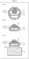
Fig. 4 illustrates a method of producing the reinforcement structure illustrated inFig. 1 . (a) to (c) ofFig. 4 are each a cross-sectional view of an adjacent section of the reinforcement structure as appears during production. -
Fig. 5 illustrates a reinforcement structure in accordance withEmbodiment 2 of the present invention. (a) ofFig. 5 is a top view of the reinforcement structure. (b) ofFig. 5 is a right side view of the reinforcement structure. (c) ofFig. 5 is a front view of the reinforcement structure. -
Fig. 6 further illustrates the reinforcement structure illustrated inFig. 5 . (a) ofFig. 6 is a cross-sectional view of an adjacent section the reinforcement structure (taken along line A-A). (b) ofFig. 6 is a cross-sectional view of a jacket-removed section of the reinforcement structure (taken along line B-B). -
Fig. 7 illustrates a reinforcement structure in accordance withEmbodiment 3 of the present invention. (a) ofFig. 7 is a top view of the reinforcement structure. (b) ofFig. 7 is a right side view of the reinforcement structure. (c) ofFig. 7 is a front view of the reinforcement structure. -
Fig. 8 further illustrates the reinforcement structure illustrated inFig. 7 . (a) ofFig. 8 is a cross-sectional view of an adjacent section the reinforcement structure (taken along line A-A). (b) ofFig. 8 is a cross-sectional view of a jacket-removed section of the reinforcement structure (taken along line B-B). - The following description will discuss, with reference to
Figs. 1 and2 , areinforcement structure 1 in accordance withEmbodiment 1 of the present invention. (a) ofFig. 1 is a top view of thereinforcement structure 1. (b) ofFig. 1 is a right side view of thereinforcement structure 1. (c) ofFig. 1 is a front view of thereinforcement structure 1. (a) ofFig. 2 is a cross-sectional view of thereinforcement structure 1, taken along line A-A. (b) ofFig. 2 is another cross-sectional view of thereinforcement structure 1, taken along line B-B. - The
reinforcement structure 1 is a structure for reinforcing a fusion splice point P at which anoptical fiber 11 and anoptical fiber 12 are fusion-spliced. Thereinforcement structure 1 includes a tension-resistance member 13, aleg part 14a, aleg part 14b, aradiator 15, a heat-shrinkable tube 16, and a low-refractive-index resin 17. - The
optical fiber 11 includes (i) abare fiber part 11a made of glass and (ii) ajacket 11b which is made of resin and covers a circumferential surface of thebare fiber part 11a. Thejacket 11b has been removed in a section (hereinafter, "jacket-removed section") I1a including the fusion splice point P. Similarly, theoptical fiber 12 includes (i) abare fiber part 12a made of glass and (ii) ajacket 12b which is made of resin and covers a circumferential surface of thebare fiber part 12a. Thejacket 12b has been removed in a section (hereinafter, "jacket-removed section") I2a including the fusion splice point P. - The tension-
resistance member 13 has a flat surface and is provided so that the flat surface faces the circumferential surfaces of theoptical fibers resistance member 13 is a plate-like member which is provided such that an upper surface of the plate-like member faces the circumferential surfaces of theoptical fibers resistance member 13 has a width which is greater than the diameter of theoptical fibers resistance member 13 need only have a high elastic modulus (at least higher than the elastic modulus of thebare fiber parts resistance member 13 include copper, copper molybdenum, and other metals. - The
leg part 14a is provided to a front end of a lower surface of the tension-resistance member 13. Theleg part 14b is provided to a rear end of the lower surface of the tension-resistance member 13. The tension-resistance member 13 is in thermal contact with the radiator 15 (described later) via theleg parts leg parts resistance member 13 which have been bonded to the tension-resistance member 13, or may be members which are a part of the tension-resistance member 13 and have been provided integrally with tension-resistance member 13. In the present embodiment, theleg parts shrinkable tube 16, and (iii) has been bonded to the front end or rear end of the lower surface of the tension-resistance member 13. A material to be used for theleg parts resistance member 13. Examples of suitable materials for theleg parts - The
radiator 15 is a member for externally dissipating heat, specifically heat which has been conducted from the tension-resistance member 13 via theleg parts radiator 15. Instead of a water-cooled plate, a known air-cooled plate may be used as theradiator 15. - The heat-
shrinkable tube 16 is a tubular member which bundles theoptical fibers resistance member 13. A material to be used for the heat-shrinkable tube 16 need only be heat-shrinkable. Examples of suitable materials for the heat-shrinkable tube 16 include a fluorocarbon resin such as (poly)tetrafluoroethylene (PTEF) and an olefin resin such as polyethylene (PE). Because the tension-resistance member 13 has a width which is greater than the diameter of theoptical fibers shrinkable tube 16 after being shrunk takes on a contour which is mountain-like when viewed in a cross section, as illustrated in (c) ofFig. 1 , and in (a) and (b) ofFig. 2 . - In the adjacent sections I1b and I2b, an inner circumferential surface of the heat-
shrinkable tube 16 is in close contact with (i) the lower surface and side surfaces of the tension-resistance member 13 and (ii) respective upper portions of the circumferential surfaces of theoptical fibers 11 and 12 (outer circumferential surface of thejacket 11b), as illustrated in (a) ofFig. 2 . Furthermore, in the adjacent sections I1b and I2b, two small gaps are formed to the left and right of theoptical fibers optical fibers resistance member 13, and the inner circumferential surface of the heat-shrinkable tube 16. In the jacket-removed sections I1a and I2a, the inner circumferential surface of the heat-shrinkable tube 16 is in close contact with the lower surface and side surfaces of the tension-resistance member 13, as illustrated in (b) ofFig. 2 . Furthermore, in the jacket-removed sections I1a and I2a, a large gap surrounding theoptical fibers resistance member 13 and the inner circumferential surface of the heat-shrinkable tube 16. The large gap and the small gaps are filled with the low-refractive-index resin 17, which has a refractive index that is lower than that of cladding (outermost shells of thebare fiber parts optical fibers index resin 17 need only (i) have a refractive index which is lower than the refractive index of the cladding of theoptical fibers shrinkable tube 16 shrinks, and hardens at normal temperature. Examples of suitable materials for the low-refractive-index resin 17 include ethylene-vinyl acetate (EVA) - In this way, the
reinforcement structure 1 is configured so that the heat-shrinkable tube 16 bundles theoptical fibers resistance member 13. This makes it possible to reinforce theoptical fibers - Furthermore, the
reinforcement structure 1 is configured such that (i) the upper surface of the tension-resistance member 13 faces the circumferential surfaces of theoptical fibers resistance member 13 is in thermal contact with theradiator 15 via theleg parts optical fibers shrinkable tube 16, a large portion of the leaked light is converted into heat in the tension-resistance member 13, and a large portion of that heat is dissipated via theradiator 15. This makes it possible to decrease the likelihood of degradation of the heat-shrinkable tube 16 caused by light which leaks from the circumferential surfaces of theoptical fibers shrinkable tube 16. - Furthermore, the
reinforcement structure 1 is configured such that the heat-shrinkable tube 16 is filled with the low-refractive-index resin 17, which has a refractive index that is lower than the refractive index of the cladding of theoptical fibers optical fibers shrinkable tube 16. It is therefore possible to further decrease the likelihood of degradation of the heat-shrinkable tube 16 caused by light which leaks from the circumferential surfaces of theoptical fibers shrinkable tube 16. - Furthermore, the
reinforcement structure 1 includes the tension-resistance member 13, which is a plate-like member having a rectangular cross section. As such, in comparison to a configuration in which the tension-resistance member 13 is a rod-like member having a circular cross section, this makes it possible to reduce, out of light which leaks from the circumferential surfaces of theoptical fibers shrinkable tube 16. It is therefore possible to further decrease the likelihood of degradation of the heat-shrinkable tube 16 caused by light which leaks from the circumferential surfaces of theoptical fibers shrinkable tube 16. - In order to confirm this, the comparative example illustrated in
Fig. 3 is considered here. (a) ofFig. 3 is a cross-sectional view of an adjacent section of a reinforcement structure in accordance with the comparative example. (b) ofFig. 3 is a cross-sectional view of a jacket-removed section of the reinforcement structure in accordance with the comparative example. The reinforcement structure in accordance with the comparative example includes a tension-resistance member which is rod-like and has a circular cross section. - In the
reinforcement structure 1 in accordance with the present embodiment, light which leaks at any direction within ± approximately 120° of an upward direction is incident upon the heat-shrinkable tube 16, as can be seen from (b) ofFig. 2 . However, in the reinforcement structure in accordance with the comparative example, light which leaks at any direction within ± approximately 135° of an upward direction is incident upon a heat-shrinkable tube, as can be seen from (b) ofFig. 3 . In other words, in thereinforcement structure 1 in accordance with the present embodiment, out of the light which leaks from theoptical fibers shrinkable tube 16 is less than that in the reinforcement structure in accordance with the comparative example. Note that even in the reinforcement structure in accordance with the comparative example, if the diameter of the tension-resistance member (the rod-like member having a circular cross section) is increased, it is possible to decrease this proportion so as to be approximately equal to that of thereinforcement structure 1 in accordance with the present embodiment. However, doing so would cause the reinforcement structure of the comparative example to have a much greater thickness than that of thereinforcement structure 1 of the present embodiment. In other words, thereinforcement structure 1 in accordance with the present embodiment makes it possible, without excessively increasing the thickness of thereinforcement structure 1, to decrease, out of the light which leaks from the circumferential surfaces of theoptical fibers shrinkable tube 16. - The following description will discuss a method of producing the
reinforcement structure 1, with reference toFig. 4 . (a) to (c) ofFig. 4 are each a cross-sectional view of thereinforcement structure 1, taken in one of the adjacent sections I1b or I2b. - The
reinforcement structure 1 can be produced by, for example, carried out the following steps in the following order. - Passing through step: First, the
optical fiber 11 is passed through aresin tube 17, and theresin tube 17 and tension-resistance member 13 are passed through the heat-shrinkable tube 16. Theresin tube 17 is a tubular member made from a thermoplastic resin and serves as a base material for the low-refractive-index resin 17. - Fusion splicing step: An end face of the
optical fiber 11 is fusion-spliced to an end face of theoptical fiber 12. - Sliding step: Next, the tension-
resistance member 13, theresin tube 17, and the heat-shrinkable tube 16 are slid so that in the jacket-removed sections I1a and I2a and the adjacent sections I1b and I2b, the upper surface of the tension-resistance member 13 faces the respective circumferential surfaces of theoptical fibers Fig. 4 illustrates a cross section of the adjacent section I1a of thereinforcement structure 1, as appears after this step has been carried out. - Heating step: Next, the heat-
shrinkable tube 16 and theresin tube 17 are heated. This shrinks the heat-shrinkable tube 16 and softens theresin tube 17. As a result, in the adjacent sections I1b and I2b, the inner circumferential surface of the heat-shrinkable tube 16 comes into close contact with (i) the lower surface and side surfaces of the tension-resistance member 13 and (ii) respective upper portions of the circumferential surfaces of theoptical fibers 11 and 12 (the outer circumferential surface of thejacket 11b). In the adjacent sections I1b and I2b, theresin tube 17 which has softened becomes the low-refractive-index resin 17 which fills the small gaps to the left and right of theoptical fibers shrinkable tube 16 comes into close contact with the lower surface and side surfaces of the tension-resistance member 13. In the jacket-removed sections I1a and I2a, theresin tube 17 which has softened becomes the low-refractive-index resin 17 which fills the large gap surrounding theoptical fibers Fig. 4 illustrates a cross section of the adjacent section I1a of thereinforcement structure 1, as appears after this step has been carried out. - Cooling step: The heat-
shrinkable tube 16 and the low-refractive-index resin 17 are cooled (for example, by natural cooling). This causes the low-refractive-index resin 17 to harden. - Bonding step: Upper surfaces of the
leg parts resistance member 13, and an upper surface of theradiator 15 is bonded to lower surfaces of theleg parts resistance member 13 and theradiator 15. (c) ofFig. 4 illustrates a cross section of the adjacent section I1a of thereinforcement structure 1, as appears after this step has been carried out. - Described above is an example method in which the fusion splicing step is carried out after the passing through step. Note, however, that a method of producing the
reinforcement structure 1 is not limited to such an example. That is, it is possible to produce thereinforcement structure 1 using a method in which the passing through step is carried out after the fusion splicing step. Furthermore, in a case where the heat-shrinkable tube 16 prior to shrinking has an inner diameter which is large enough to allow the tension-resistance member 13 to pass through the heat-shrinkable tube 16 even after theleg parts resistance member 13, a step of bonding the upper surfaces of theleg parts resistance member 13 may be carried out before the passing through step. - The following description will discuss, with reference to
Figs. 5 and6 , areinforcement structure 2 in accordance withEmbodiment 2 of the present invention. (a) ofFig. 5 is a top view of thereinforcement structure 2. (b) ofFig. 5 is a right side view of thereinforcement structure 2. (c) ofFig. 5 is a front view of thereinforcement structure 2. (a) ofFig. 6 is a cross-sectional view of thereinforcement structure 2, taken along line A-A. (b) ofFig. 6 is another cross-sectional view of thereinforcement structure 2, taken along line B-B. - The
reinforcement structure 2 in accordance with the present embodiment is a structure for reinforcing a fusion splice point P at which anoptical fiber 21 and anoptical fiber 22 are fusion-spliced. Similarly to thereinforcement structure 1 in accordance withEmbodiment 1, thereinforcement structure 2 includes a tension-resistance member 23, aleg part 24a, aleg part 24b, aleg part 24c, aradiator 25, a heat-shrinkable tube 26, and a low-refractive-index resin 27. - The tension-
resistance member 23, theleg parts radiator 25, the heat-shrinkable tube 26, and the low-refractive-index resin 27 of thereinforcement structure 2 of the present embodiment respectively correspond to the tension-resistance member 13, theleg parts radiator 15, the heat-shrinkable tube 16, and the low-refractive-index resin 17 of thereinforcement structure 1 ofEmbodiment 1. - The
reinforcement structure 2 of the present embodiment differs from thereinforcement structure 1 ofEmbodiment 1 in that (i) theleg part 24c is provided to the center of a lower surface of the tension-resistance member 23 and (ii) the heat-shrinkable tube 26 includes acutout portion 26a through which theleg part 24c is to be passed. The tension-resistance member 23 is in thermal contact with theradiator 25 via theleg part 24a, theleg part 24b, and theleg part 24c. - Light which propagates through the
optical fibers resistance member 23 is, relatively, larger in a central portion which overlaps with the fusion splice point P, and smaller at both ends of the tension-resistance member 23. With the above configuration, the tension-resistance member 23 is in thermal contact with theradiator 25 not only at both ends of the tension-resistance member 23, where the amount of heat generated is relatively small, but also at a central portion of the tension-resistance member 23, where the amount of heat generated is relatively large. In comparison to thereinforcement structure 1 ofEmbodiment 1, this configuration enables even more efficient external dissipation of heat generated in the tension-resistance member 23. - The following description will discuss, with reference to
Figs. 7 and8 , areinforcement structure 3 in accordance withEmbodiment 3 of the present invention. (a) ofFig. 7 is a top view of thereinforcement structure 3. (b) ofFig. 7 is a right side view of thereinforcement structure 3. (c) ofFig. 7 is a front view of thereinforcement structure 3. (a) ofFig. 8 is a cross-sectional view of thereinforcement structure 3, taken along line A-A. (b) ofFig. 8 is another cross-sectional view of thereinforcement structure 3, taken along line B-B. - The
reinforcement structure 3 in accordance with the present embodiment is a structure for reinforcing a fusion splice point P at which anoptical fiber 31 and anoptical fiber 32 are fusion-spliced. Similarly to thereinforcement structure 1 in accordance withEmbodiment 1, thereinforcement structure 3 includes a tension-resistance member 33, aleg part 34a, aleg part 34b, aradiator 35, a heat-shrinkable tube 36, and a low-refractive-index resin 37. - The tension-
resistance member 33, theleg parts radiator 35, the heat-shrinkable tube 36, and the low-refractive-index resin 37 of thereinforcement structure 3 of the present embodiment respectively correspond to the tension-resistance member 13, theleg parts radiator 15, the heat-shrinkable tube 16, and the low-refractive-index resin 17 of thereinforcement structure 1 ofEmbodiment 1. - The
reinforcement structure 3 of the present embodiment differs from thereinforcement structure 1 ofEmbodiment 1 in that (i)U-shaped grooves optical fibers optical fibers resistance member 33. - With the above configuration, in the jacket-removed sections I1a and I2a, the
optical fibers resistance member 33. This makes is possible to decrease, out of light which leaks from the circumferential surfaces of theoptical fibers shrinkable tube 36. It is therefore possible to decrease the likelihood of degradation of the heat-shrinkable tube 36 caused by light which leaks from the circumferential surfaces of theoptical fibers shrinkable tube 36. Furthermore, with the above configuration, because theoptical fibers resistance member 33 in the jacket-removed sections I1a and I2a, it is possible to prevent theoptical fibers optical fibers - A reinforcement structure in accordance with an aspect of the present invention is a reinforcement structure for reinforcing a fusion splice point at which a plurality of optical fibers are fusion-spliced, the reinforcement structure including: a tension-resistance member; a heat-shrinkable tube which bundles the plurality of optical fibers and the tension-resistance member; and a radiator which is in thermal contact with the tension-resistance member, the tension-resistance member having a flat surface which faces respective circumferential surfaces of the plurality of optical fibers.
- With the above configuration, the optical fiber and the tension-resistance member are bundled together by the heat-shrinkable tube. This makes it possible to reinforce the optical fiber in a simple manner. Furthermore, the tension-resistance member has a flat surface facing the circumferential surface of the optical fiber and is in thermal contact with the radiator. As such, even if light leaks from the circumferential surface of the optical fiber in the heat-shrinkable tube, a large portion of the leaked light is converted into heat in the tension-resistance member, and a large portion of that heat is dissipated via the radiator. It is therefore possible to decrease the likelihood of degradation of the optical fiber caused by light which leaks from the circumferential surface of the optical fiber and heats the optical fiber.
- The reinforcement structure in accordance with an embodiment of the present invention is preferably configured such that the heat-shrinkable tube is filled with a low-refractive-index resin whose refractive index is lower than a refractive index of cladding of each of the plurality of optical fibers.
- With the above configuration, the heat-shrinkable tube is filled with a low-refractive-index resin whose refractive index in lower than a refractive index of cladding of the optical fiber. This makes it possible to decrease the amount of light which leaks from the circumferential surface of the optical fiber in the heat-shrinkable tube. It is therefore possible to further decrease the likelihood of degradation of the optical fiber caused by light which leaks from the circumferential surface of the optical fiber and heats the optical fiber.
- The reinforcement structure in accordance with an embodiment of the present invention is preferably configured such that the tension-resistance member is a plate-like member whose upper surface faces the respective circumferential surfaces of the plurality of optical fibers.
- The above configuration makes it possible, without excessively increasing the thickness of the reinforcement structure, to decrease, out of the light which leaks from the circumferential surface of the optical fiber, the proportion of light which is incident upon the heat-shrinkable tube. It is therefore possible to further decrease the likelihood of degradation of the heat-shrinkable tube caused by light which leaks from the circumferential surface of the optical fiber and heats the heat-shrinkable tube.
- The reinforcement structure in accordance with an embodiment of the present invention is preferably configured such that the flat surface of the tension-resistance member has a width which is greater than a diameter of each of the plurality of optical fibers.
- The above configuration makes it possible to further decrease, out of the light which leaks from the circumferential surface of the optical fiber, the proportion of light which is incident upon the heat-shrinkable tube. It is therefore possible to further decrease the likelihood of degradation of the heat-shrinkable tube caused by light which leaks from the circumferential surface of the optical fiber and heats the heat-shrinkable tube.
- The reinforcement structure in accordance with an embodiment of the present invention is preferably configured such that: the heat-shrinkable tube includes a cutout portion; and the tension-resistance member is in thermal contact with the radiator via a leg part which (i) is provided to a lower surface of the tension-resistance member in a region in which the tension-resistance member faces the fusion splice point and (ii) passes through the cutout portion.
- The above configuration makes it possible to bring the tension-resistance member into thermal contact with the radiator via the leg part in a region in which the tension-resistance member faces the fusion splice point, i.e., a region of the tension-resistance member in which an amount of generated heat is relatively large. This makes it possible to more efficiently dissipate heat generated in the tension-resistance member.
- The reinforcement structure in accordance with an embodiment of the present invention is preferably configured such that a groove for holding the plurality of optical fibers is formed in the upper surface of the tension-resistance member outside a jacket-removed section, such that in the jacket-removed section, the respective circumferential surfaces of the plurality of optical fibers are in contact with the upper surface of the tension-resistance member.
- With the above configuration, in the jacket-removed section, the optical fiber has been brought closer to the upper surface of the tension-resistance member. This makes is possible to decrease, out of light which leaks from the circumferential surface of the optical fiber, a proportion of light which is incident upon the heat-shrinkable tube. It is therefore possible to decrease the likelihood of degradation of the heat-shrinkable tube caused by light which leaks from the circumferential surface of the optical fiber and heats the heat-shrinkable tube. Furthermore, with the above configuration, because the optical fiber is in contact with the upper surface of the tension-resistance member in the jacket-removed section, it is possible to prevent the optical fiber from bending in a vertical direction. This makes it possible to prevent an increase in damage which could be caused by bending of the optical fiber.
- The reinforcement structure in accordance with an embodiment of the present invention is preferably configured such that the radiator is a water-cooled plate.
- The above configuration makes it possible to more efficiently dissipate heat generated in the tension-resistance member.
- The present invention is not limited to the foregoing embodiments (examples), but can be altered by a skilled person in the art within the scope of the claims. The present invention also encompasses, in its technical scope, any embodiment derived by combining technical means disclosed in differing embodiments.
-
- 11, 12, 21, 22, 31, 32 Optical fiber
- 11a, 12a, 21a, 22a, 31a, 32a Bare fiber part
- 11b, 12b, 21b, 22b, 31b, 32b Jacket
- 13, 23, 33 Tension-resistance member
- 33a, 33b U-shaped groove
- 14a, 14b, 24a, 24b, 24c, 34a, 34bLeg part
- 15, 25, 35 Radiator
- 16, 26, 36 Heat-shrinkable tube
- 26a Cutout portion
- 17, 27, 37 Low-refractive-index resin
- P Fusion splice point
Claims (7)
- A reinforcement structure for reinforcing a fusion splice point at which a plurality of optical fibers are fusion-spliced, the reinforcement structure comprising:a tension-resistance member;a heat-shrinkable tube which bundles the plurality of optical fibers and the tension-resistance member; anda radiator which is in thermal contact with the tension-resistance member,the tension-resistance member having a flat surface which faces respective circumferential surfaces of the plurality of optical fibers.
- The reinforcement structure according to claim 1, wherein the heat-shrinkable tube is filled with a low-refractive-index resin whose refractive index is lower than a refractive index of cladding of each of the plurality of optical fibers.
- The reinforcement structure according to claim 1 or 2, wherein the tension-resistance member is a plate-like member whose upper surface faces the respective circumferential surfaces of the plurality of optical fibers.
- The reinforcement structure according to any one of claims 1 to 3, wherein the flat surface of the tension-resistance member has a width which is greater than a diameter of each of the plurality of optical fibers.
- The reinforcement structure according to claim 3 or 4, wherein:the heat-shrinkable tube includes a cutout portion; andthe tension-resistance member is in thermal contact with the radiator via a leg part which (i) is provided to a lower surface of the tension-resistance member in a region in which the tension-resistance member faces the fusion splice point and (ii) passes through the cutout portion.
- The reinforcement structure according to claim 3 or 4, wherein a groove for holding the plurality of optical fibers is formed in the upper surface of the tension-resistance member outside a jacket-removed section, such that in the jacket-removed section, the respective circumferential surfaces of the plurality of optical fibers are in contact with the upper surface of the tension-resistance member.
- The reinforcement structure according to any one of claims 1 to 6, wherein the radiator is a water-cooled plate.
Applications Claiming Priority (2)
| Application Number | Priority Date | Filing Date | Title |
|---|---|---|---|
| JP2016151101A JP6381591B2 (en) | 2016-08-01 | 2016-08-01 | Reinforced structure |
| PCT/JP2017/020262 WO2018025486A1 (en) | 2016-08-01 | 2017-05-31 | Reinforcement structure |
Publications (2)
| Publication Number | Publication Date |
|---|---|
| EP3492957A1 true EP3492957A1 (en) | 2019-06-05 |
| EP3492957A4 EP3492957A4 (en) | 2020-01-15 |
Family
ID=61073703
Family Applications (1)
| Application Number | Title | Priority Date | Filing Date |
|---|---|---|---|
| EP17836593.8A Ceased EP3492957A4 (en) | 2016-08-01 | 2017-05-31 | REINFORCEMENT STRUCTURE |
Country Status (5)
| Country | Link |
|---|---|
| US (1) | US11226449B2 (en) |
| EP (1) | EP3492957A4 (en) |
| JP (1) | JP6381591B2 (en) |
| CN (1) | CN109477937A (en) |
| WO (1) | WO2018025486A1 (en) |
Families Citing this family (2)
| Publication number | Priority date | Publication date | Assignee | Title |
|---|---|---|---|---|
| JP7508471B2 (en) * | 2019-10-01 | 2024-07-01 | 古河電気工業株式会社 | Reinforcement sleeve, structure and method for reinforcing optical fiber connection |
| JP7585057B2 (en) * | 2021-01-19 | 2024-11-18 | 古河電気工業株式会社 | Reinforcement sleeve and reinforcement structure for optical fiber connection |
Family Cites Families (15)
| Publication number | Priority date | Publication date | Assignee | Title |
|---|---|---|---|---|
| JPS63188606U (en) | 1987-05-26 | 1988-12-02 | ||
| JPH085858A (en) * | 1994-06-20 | 1996-01-12 | Fujitsu Ltd | Optical fiber connecting portion reinforcing structure, fiber module using the same, and method for manufacturing the structure |
| JPH08248256A (en) * | 1995-03-14 | 1996-09-27 | Sumitomo Electric Ind Ltd | Reinforcing method and reinforcing structure of optical fiber fusion splicing part |
| JP2004356421A (en) * | 2003-05-29 | 2004-12-16 | Fujikura Ltd | Optical fiber laser |
| JP2006201264A (en) * | 2005-01-18 | 2006-08-03 | Fujikura Ltd | Heat shrinkable sleeve heating device and optical fiber for reinforcing optical fiber connection |
| JP4305468B2 (en) * | 2006-04-13 | 2009-07-29 | 住友電気工業株式会社 | Fusion splicer |
| JP4982330B2 (en) | 2007-11-02 | 2012-07-25 | 株式会社フジクラ | Optical fiber fusion splicing structure, residual pumping light removal method, optical amplifier and optical fiber laser |
| JP5294114B2 (en) * | 2009-01-26 | 2013-09-18 | 株式会社メガオプト | Optical module |
| JP5276483B2 (en) * | 2009-03-11 | 2013-08-28 | 住友電気工業株式会社 | Method and structure for reinforcing connection |
| JP2011133838A (en) * | 2009-11-25 | 2011-07-07 | Sumitomo Electric Ind Ltd | Reinforcing member and reinforcing method for fusion spliced portions of optical fibers |
| WO2013001734A1 (en) | 2011-06-29 | 2013-01-03 | パナソニック株式会社 | Fiber laser |
| JP5607590B2 (en) * | 2011-08-29 | 2014-10-15 | 古河電気工業株式会社 | Reinforcing sleeve and optical fiber core wire fusion splicing method |
| JP6010566B2 (en) | 2014-02-03 | 2016-10-19 | 株式会社フジクラ | Leakage light removal structure and fiber laser |
| US10261329B2 (en) * | 2016-08-26 | 2019-04-16 | Nlight, Inc. | Fiber combiner with input port dump |
| JP6715279B2 (en) * | 2018-03-16 | 2020-07-01 | 株式会社フジクラ | Optical device |
-
2016
- 2016-08-01 JP JP2016151101A patent/JP6381591B2/en active Active
-
2017
- 2017-05-31 EP EP17836593.8A patent/EP3492957A4/en not_active Ceased
- 2017-05-31 WO PCT/JP2017/020262 patent/WO2018025486A1/en not_active Ceased
- 2017-05-31 US US16/316,122 patent/US11226449B2/en not_active Expired - Fee Related
- 2017-05-31 CN CN201780042726.3A patent/CN109477937A/en active Pending
Also Published As
| Publication number | Publication date |
|---|---|
| US11226449B2 (en) | 2022-01-18 |
| CN109477937A (en) | 2019-03-15 |
| US20210286131A1 (en) | 2021-09-16 |
| JP2018021952A (en) | 2018-02-08 |
| WO2018025486A1 (en) | 2018-02-08 |
| JP6381591B2 (en) | 2018-08-29 |
| EP3492957A4 (en) | 2020-01-15 |
Similar Documents
| Publication | Publication Date | Title |
|---|---|---|
| US8665916B2 (en) | Fiber laser | |
| KR101633799B1 (en) | Method of fusing optical fibers within a splice package | |
| US7410308B2 (en) | Fiber optic cable splice | |
| US8620129B2 (en) | Cable pulling assembly | |
| CN112888978B (en) | Optical fiber fanout assembly with ribbonized interface for multi-way fusion splicing and method of making same | |
| CN201156094Y (en) | A sleeve that protects the connection between optical fibers | |
| JP6370286B2 (en) | High efficiency pump signal combiner for high power fiber amplifier and laser applications | |
| KR20120101405A (en) | Reinforcing member and reinforcing method for fusion spliced portions of optical fibers | |
| US11327231B2 (en) | Flexible splice protector assembly and method for preparing same | |
| US20190204502A1 (en) | Optical fiber heat dissipation package | |
| US11226449B2 (en) | Reinforcement structure | |
| WO2010067510A1 (en) | Optical fiber collector, optical amplifier, and fiber laser device | |
| US9091800B2 (en) | Glass buffers | |
| US10833470B2 (en) | Optical fiber and fiber laser | |
| JP2015175958A (en) | Semiconductor laser module, semiconductor laser light source, and semiconductor laser system | |
| US20070160332A1 (en) | Apparatus and method for splicing optical fibers and reconstructing fiber-optic cables | |
| JP2008226886A (en) | Optical pumping device, optical amplifier, fiber laser, multi-core fiber for optical pumping device and manufacturing method thereof | |
| US11886009B2 (en) | Coating fusion spliced optical fibers and subsequent processing methods thereof | |
| JP2014193806A5 (en) | ||
| US9164241B2 (en) | Low loss passive optical hub for use in the plastic optical fiber networks | |
| US20210373266A1 (en) | Compact package for high-aspect-ratio rectangular (harr) optical fiber or other optical fiber | |
| WO2020264126A1 (en) | Reverse pumped fiber amplifier with cladding light stripper between segments of active fiber | |
| JP2004117443A (en) | Optical fiber coupler | |
| JP7809683B2 (en) | Optical fiber connector and method for manufacturing the same | |
| AU2019201283A1 (en) | Connection structure and method of producing connection structure |
Legal Events
| Date | Code | Title | Description |
|---|---|---|---|
| STAA | Information on the status of an ep patent application or granted ep patent |
Free format text: STATUS: THE INTERNATIONAL PUBLICATION HAS BEEN MADE |
|
| PUAI | Public reference made under article 153(3) epc to a published international application that has entered the european phase |
Free format text: ORIGINAL CODE: 0009012 |
|
| STAA | Information on the status of an ep patent application or granted ep patent |
Free format text: STATUS: REQUEST FOR EXAMINATION WAS MADE |
|
| 17P | Request for examination filed |
Effective date: 20190102 |
|
| AK | Designated contracting states |
Kind code of ref document: A1 Designated state(s): AL AT BE BG CH CY CZ DE DK EE ES FI FR GB GR HR HU IE IS IT LI LT LU LV MC MK MT NL NO PL PT RO RS SE SI SK SM TR |
|
| AX | Request for extension of the european patent |
Extension state: BA ME |
|
| DAV | Request for validation of the european patent (deleted) | ||
| DAX | Request for extension of the european patent (deleted) | ||
| A4 | Supplementary search report drawn up and despatched |
Effective date: 20191217 |
|
| RIC1 | Information provided on ipc code assigned before grant |
Ipc: G02B 6/255 20060101AFI20191212BHEP |
|
| STAA | Information on the status of an ep patent application or granted ep patent |
Free format text: STATUS: EXAMINATION IS IN PROGRESS |
|
| 17Q | First examination report despatched |
Effective date: 20220517 |
|
| REG | Reference to a national code |
Ref country code: DE Ref legal event code: R003 |
|
| STAA | Information on the status of an ep patent application or granted ep patent |
Free format text: STATUS: THE APPLICATION HAS BEEN REFUSED |
|
| 18R | Application refused |
Effective date: 20251015 |