EP3492926B1 - Pipette tip, liquid delivery method and liquid delivery system - Google Patents
Pipette tip, liquid delivery method and liquid delivery system Download PDFInfo
- Publication number
- EP3492926B1 EP3492926B1 EP17834111.1A EP17834111A EP3492926B1 EP 3492926 B1 EP3492926 B1 EP 3492926B1 EP 17834111 A EP17834111 A EP 17834111A EP 3492926 B1 EP3492926 B1 EP 3492926B1
- Authority
- EP
- European Patent Office
- Prior art keywords
- pipette tip
- film
- channel
- liquid
- distal end
- Prior art date
- Legal status (The legal status is an assumption and is not a legal conclusion. Google has not performed a legal analysis and makes no representation as to the accuracy of the status listed.)
- Active
Links
Images


Classifications
-
- B—PERFORMING OPERATIONS; TRANSPORTING
- B01—PHYSICAL OR CHEMICAL PROCESSES OR APPARATUS IN GENERAL
- B01L—CHEMICAL OR PHYSICAL LABORATORY APPARATUS FOR GENERAL USE
- B01L3/00—Containers or dishes for laboratory use, e.g. laboratory glassware; Droppers
- B01L3/02—Burettes; Pipettes
- B01L3/021—Pipettes, i.e. with only one conduit for withdrawing and redistributing liquids
-
- B—PERFORMING OPERATIONS; TRANSPORTING
- B01—PHYSICAL OR CHEMICAL PROCESSES OR APPARATUS IN GENERAL
- B01L—CHEMICAL OR PHYSICAL LABORATORY APPARATUS FOR GENERAL USE
- B01L3/00—Containers or dishes for laboratory use, e.g. laboratory glassware; Droppers
- B01L3/02—Burettes; Pipettes
- B01L3/0275—Interchangeable or disposable dispensing tips
-
- B—PERFORMING OPERATIONS; TRANSPORTING
- B01—PHYSICAL OR CHEMICAL PROCESSES OR APPARATUS IN GENERAL
- B01L—CHEMICAL OR PHYSICAL LABORATORY APPARATUS FOR GENERAL USE
- B01L3/00—Containers or dishes for laboratory use, e.g. laboratory glassware; Droppers
- B01L3/02—Burettes; Pipettes
- B01L3/0286—Ergonomic aspects, e.g. form or arrangement of controls
-
- B—PERFORMING OPERATIONS; TRANSPORTING
- B01—PHYSICAL OR CHEMICAL PROCESSES OR APPARATUS IN GENERAL
- B01L—CHEMICAL OR PHYSICAL LABORATORY APPARATUS FOR GENERAL USE
- B01L3/00—Containers or dishes for laboratory use, e.g. laboratory glassware; Droppers
- B01L3/50—Containers for the purpose of retaining a material to be analysed, e.g. test tubes
- B01L3/502—Containers for the purpose of retaining a material to be analysed, e.g. test tubes with fluid transport, e.g. in multi-compartment structures
-
- C—CHEMISTRY; METALLURGY
- C12—BIOCHEMISTRY; BEER; SPIRITS; WINE; VINEGAR; MICROBIOLOGY; ENZYMOLOGY; MUTATION OR GENETIC ENGINEERING
- C12M—APPARATUS FOR ENZYMOLOGY OR MICROBIOLOGY; APPARATUS FOR CULTURING MICROORGANISMS FOR PRODUCING BIOMASS, FOR GROWING CELLS OR FOR OBTAINING FERMENTATION OR METABOLIC PRODUCTS, i.e. BIOREACTORS OR FERMENTERS
- C12M1/00—Apparatus for enzymology or microbiology
-
- G—PHYSICS
- G01—MEASURING; TESTING
- G01N—INVESTIGATING OR ANALYSING MATERIALS BY DETERMINING THEIR CHEMICAL OR PHYSICAL PROPERTIES
- G01N1/00—Sampling; Preparing specimens for investigation
-
- G—PHYSICS
- G01—MEASURING; TESTING
- G01N—INVESTIGATING OR ANALYSING MATERIALS BY DETERMINING THEIR CHEMICAL OR PHYSICAL PROPERTIES
- G01N35/00—Automatic analysis not limited to methods or materials provided for in any single one of groups G01N1/00 - G01N33/00; Handling materials therefor
- G01N35/10—Devices for transferring samples or any liquids to, in, or from, the analysis apparatus, e.g. suction devices, injection devices
-
- B—PERFORMING OPERATIONS; TRANSPORTING
- B01—PHYSICAL OR CHEMICAL PROCESSES OR APPARATUS IN GENERAL
- B01L—CHEMICAL OR PHYSICAL LABORATORY APPARATUS FOR GENERAL USE
- B01L2200/00—Solutions for specific problems relating to chemical or physical laboratory apparatus
- B01L2200/08—Ergonomic or safety aspects of handling devices
- B01L2200/087—Ergonomic aspects
-
- B—PERFORMING OPERATIONS; TRANSPORTING
- B01—PHYSICAL OR CHEMICAL PROCESSES OR APPARATUS IN GENERAL
- B01L—CHEMICAL OR PHYSICAL LABORATORY APPARATUS FOR GENERAL USE
- B01L2300/00—Additional constructional details
- B01L2300/04—Closures and closing means
- B01L2300/041—Connecting closures to device or container
- B01L2300/044—Connecting closures to device or container pierceable, e.g. films, membranes
-
- B—PERFORMING OPERATIONS; TRANSPORTING
- B01—PHYSICAL OR CHEMICAL PROCESSES OR APPARATUS IN GENERAL
- B01L—CHEMICAL OR PHYSICAL LABORATORY APPARATUS FOR GENERAL USE
- B01L2300/00—Additional constructional details
- B01L2300/08—Geometry, shape and general structure
- B01L2300/0848—Specific forms of parts of containers
- B01L2300/0858—Side walls
-
- B—PERFORMING OPERATIONS; TRANSPORTING
- B01—PHYSICAL OR CHEMICAL PROCESSES OR APPARATUS IN GENERAL
- B01L—CHEMICAL OR PHYSICAL LABORATORY APPARATUS FOR GENERAL USE
- B01L2400/00—Moving or stopping fluids
- B01L2400/04—Moving fluids with specific forces or mechanical means
- B01L2400/0403—Moving fluids with specific forces or mechanical means specific forces
- B01L2400/0406—Moving fluids with specific forces or mechanical means specific forces capillary forces
-
- G—PHYSICS
- G01—MEASURING; TESTING
- G01N—INVESTIGATING OR ANALYSING MATERIALS BY DETERMINING THEIR CHEMICAL OR PHYSICAL PROPERTIES
- G01N21/00—Investigating or analysing materials by the use of optical means, i.e. using sub-millimetre waves, infrared, visible or ultraviolet light
- G01N21/62—Systems in which the material investigated is excited whereby it emits light or causes a change in wavelength of the incident light
- G01N21/63—Systems in which the material investigated is excited whereby it emits light or causes a change in wavelength of the incident light optically excited
- G01N21/64—Fluorescence; Phosphorescence
-
- G—PHYSICS
- G01—MEASURING; TESTING
- G01N—INVESTIGATING OR ANALYSING MATERIALS BY DETERMINING THEIR CHEMICAL OR PHYSICAL PROPERTIES
- G01N21/00—Investigating or analysing materials by the use of optical means, i.e. using sub-millimetre waves, infrared, visible or ultraviolet light
- G01N21/62—Systems in which the material investigated is excited whereby it emits light or causes a change in wavelength of the incident light
- G01N21/63—Systems in which the material investigated is excited whereby it emits light or causes a change in wavelength of the incident light optically excited
- G01N21/64—Fluorescence; Phosphorescence
- G01N21/645—Specially adapted constructive features of fluorimeters
- G01N21/648—Specially adapted constructive features of fluorimeters using evanescent coupling or surface plasmon coupling for the excitation of fluorescence
Definitions
- the present invention relates to a liquid delivery method and a liquid delivery system, for injecting a liquid into a channel of a channel chip and sucking a liquid from the channel of the channel chip with use of a pipette tip, and relates to a pipette tip that can be used in these.
- Biochemical reactions such as antigen-antibody reactions are used in biochemical examinations.
- a fluorescent immunoassay hereinafter also referred to as "FIA”
- a substance to be detected (antigen) is reacted with a labeling substance containing a fluorescent substance.
- fluorescence emitted by the fluorescent substance is detected by irradiating, with excitation light, the substance to be detected that has been labeled with the labeling substance.
- an intensity of the detected fluorescence and the like an amount of the substance to be detected is specified.
- SPFS surface plasmon-field enhanced fluorescence spectroscopy
- a first capturing body e.g., a primary antibody
- a reaction field for capturing the substance to be detected.
- the reaction field is formed in a fine channel.
- a sample liquid (specimen) containing the substance to be detected is injected into this channel, thereby binding the substance to be detected to the first capturing body (primary reaction).
- a fluorescent labeling liquid containing a second capturing body e.g., a secondary antibody
- the substance to be detected is indirectly labeled with the fluorescent substance.
- the fluorescent substance is excited by the electric field enhanced by surface plasmon resonance (hereinafter also referred to as "SPR") to emit fluorescence.
- SPR surface plasmon resonance
- JP 2013-185967 A discloses a biochemical examination apparatus that detects a substance to be detected with use of SPFS.
- This biochemical examination apparatus includes: an inspection chip having a channel formed with a reaction field inside; a reagent chip having a plurality of vessels each containing different types of reagents; a liquid delivery mechanism to move a liquid between the reagent chip and the inspection chip; a conveyance mechanism to move the inspection chip; a measurement unit to irradiate the inspection chip with excitation light and to detect fluorescence from the inspection chip, and the like.
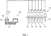
- FIG. 1 is a schematic view showing reagent chip 10 and inspection chip 20 in the biochemical examination apparatus described in JP 2013-185967 A .
- reagent chip 10 includes: cleaning liquid vessel 11 containing a cleaning liquid; specimen vessel 12 containing a specimen; diluent vessel 13 containing a diluent; sample liquid vessel 14 containing a sample liquid obtained by diluting the specimen with the diluent; and fluorescent labeling liquid vessel 15 containing a fluorescent labeling liquid.
- reagent chip 10 is attached with pipette tip 16. Pipette tip 16 is attached to the liquid delivery mechanism to be used.
- Inspection chip 20 has channel 21 and pipette tip insertion part (insertion hole) 22 connected to one end of channel 21.
- pipette tip insertion part 22 An opening of pipette tip insertion part 22 is closed with seal (insertion hole hermetic seal) 23.
- seal insertion hole hermetic seal
- pipette tip 16 with an outer diameter gradually increasing from a distal end to a proximal end except for the vicinity of the proximal end. In the vicinity of the proximal end, the outer diameter of pipette tip 16 is constant. An inner diameter of pipette tip 16 gradually increases from the distal end toward the proximal end, from the distal end to the proximal end. A taper angle of an inclined surface of an outer surface of pipette tip 16 is constant, and a taper angle of an inclined surface on an inner surface is also constant.
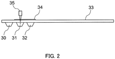
- FIG. 2 is a schematic view showing the reaction vessel described in WO 2006/104213 A1 . As shown in FIG.
- the reaction vessel has sample injection part 30, reagent container 31, mineral oil container 32, and reaction part 33, and openings of reagent container 31 and mineral oil container 32 are closed with film 34.
- the liquid is sucked into pipette tip 35 by pipette tip 35 pierced into film 34.
- pipette tip 35 with an outer diameter gradually increasing from a distal end to a proximal end except for the vicinity of the proximal end. In the vicinity of the proximal end, the outer diameter of pipette tip 35 is constant. A taper angle of an inclined surface of an outer surface of pipette tip 35 is constant.
- JP 2008 -020376 A discloses a nozzle tip comprising three bending portions from an opening at a distal end to an upward portion, and five sections that are divided by the bending portions into a first to fifth sections.
- angles opening upward of inner surfaces of each section are defined as ⁇ 1, ⁇ 2, ⁇ 3, ⁇ 4; each requirement ⁇ 1> ⁇ 2, ⁇ 2 ⁇ 3 and ⁇ 3> ⁇ 4 is satisfied; the ⁇ 1 is set in the range of 3 to 7°; the ⁇ 2 is set in the range of 1 to 3° and the inner diameter d1 is set in the range 1.8 to 2.2 mm.
- EP 1 839 752 A2 discloses disposable pipette tip that can prevent a tight fit with another pipette tip without providing a separating mechanism in a supplying apparatus.
- the disposable pipette tip comprises: an attachment section for being attached to the dispensing device, and a liquid containing section for containing a liquid aspirated by the dispensing device, which is continually located to the attachment section, has a tapered distal end and comprises a tight fit preventing part which is located adjacent to the tapered distal end and prevents a tight fit with another pipette tip.
- US 4 917 274 A discloses a miniscule fluid volume dispenser tip including a tube having an elongated constant diameter small bore disposed at the outlet end thereof with a fluid reservoir disposed at the opposite internal end thereof and plural inflection parts along an inner surface, the outlet end of the dispenser tip being sharply cut away to reduce surface area to which the dispensed liquid may attach.
- reagent chip 10 there is used a vessel that has an opening closed with a first film and contains a liquid inside
- inspection chip 20 there is used a channel chip that includes a channel and a pipette tip insertion part connected to one end of the channel and having its opening closed with a second film. Further, the pipette tip is attached to a pipette nozzle of a pipette (liquid delivery mechanism), to be used.
- the pipette tip is pierced into the first film of the vessel to suck the liquid contained in the vessel into the pipette tip, and then the pipette tip is pierced into the second film of the channel chip to inject the liquid held in the pipette tip into the channel via the pipette tip insertion part.
- the pipette tip is pierced into the second film of the channel chip to suck the liquid in the channel into the pipette tip via the pipette tip insertion part, and then the pipette tip is pierced into the first film of a used vessel or an empty vessel (used as a waste liquid container) to discharge the liquid held in the pipette tip into the vessel.
- through holes are formed in the first film of the vessel and the second film of the channel chip by piercing the pipette tip. After this, the vessel containing the waste liquid is discarded.
- the channel chip having the channel and the pipette tip insertion part with the opening closed with the second film, and the pipette tip it is necessary to satisfy the following requirement (1), and it is further preferable to satisfy the following requirements (2) and (3).
- an object of the present invention is to provide a pipette tip to be used in combination with a vessel having an opening closed with a first film, and with a channel chip having a channel and a pipette tip insertion part with an opening closed with a second film.
- the pipette tip satisfies the following three requirements: (1) properly performing injection of a liquid into the channel of the channel chip and suction of a liquid from the channel; (2) reducing a size of a through hole formed in the first film of the vessel; and (3) reducing a size of the pipette tip and the pipette nozzle.
- another object of the present invention is to provide a liquid delivery method and a liquid delivery system using this pipette tip.
- a pipette tip according to the present invention is a pipette tip with the features of claim 1 to be attached to a pipette nozzle and used in a liquid delivery system.
- the pipette tip including inter alia: a first part that includes a distal end of the pipette tip and has an outer diameter gradually increasing from a distal end side toward a proximal end side; a second part that is arranged adjacent to the first part on a proximal end side, has an outer diameter being unchanged or gradually increasing from a distal end side toward a proximal end side, and has a smaller taper angle of an outer surface than a taper angle of an outer surface of the first part; a third part that is arranged adjacent to the second part on a proximal end side, has an outer diameter gradually increasing from a distal end side toward a proximal end side, and has a larger taper angle of an outer surface than a taper angle of an outer surface of the first part; and a fourth
- a liquid delivery method includes the features of claim 7 comprising: a first step of sucking a liquid contained in a vessel into a pipette tip in a state where the pipette tip is inserted through a first film into the vessel of which opening is closed with the first film; a second step of injecting a liquid retained in the pipette tip into a channel in a state where the pipette tip is inserted through a second film into a pipette tip insertion part of a channel chip having the channel and the pipette tip insertion part, the pipette tip insertion part being connected to one end of the channel and having an opening closed with the second film; and a third step of sucking a liquid in the channel into the pipette tip in a state where the pipette tip is inserted through the second film into the pipette tip insertion part of the channel chip, in which A > B is satisfied where A is a length along an axial direction of the pipette tip from a distal
- a liquid delivery system includes the features of claim 6 comprising: a vessel that has an opening closed with a first film and contains a liquid inside; a channel chip that has a channel and a pipette tip insertion part, the pipette tip insertion part being connected to one end of the channel and having an opening closed with a second film; and a pipette that has a pipette nozzle and a pipette tip according to the invention attached to the pipette nozzle.
- FIG. 3 is a schematic view showing a configuration of liquid delivery system 100 according to an embodiment of the present invention.
- liquid delivery system 100 includes reagent chip 200, channel chip 300, and pipette 400.
- FIG. 4A is a plan view of reagent chip 200
- FIG. 4B is a cross-sectional view taken along line B-B in FIG. 4A .
- liquids contained in several vessels are omitted.
- reagent chip 200 includes a plurality of vessels 210a to 210h, and first film 220 that closes openings of some of vessels 210b to 210h among the plurality of vessels 210a to 210h.
- the plurality of vessels 210a to 210h are bottomed recesses configured to be able to contain a liquid (e.g., a specimen, a reagent, waste liquid, and the like).
- reagent chip 200 has eight vessels 210a to 210h.
- First vessel 210a to contain a specimen and a seventh vessel 210g to collect waste liquid are empty in a state before use, while different reagents are respectively contained in second vessel 210b, third vessel 210c, fourth vessel 210d, fifth vessel 210e, sixth vessel 210f, and eighth vessel 210h that are for storage of various reagents.
- a type of the reagent is not particularly limited, and is appropriately selected depending on use of reagent chip 200.
- Each of vessels 210b to 210f and 210h of reagent chip 200 according to the present embodiment to be used for SPFS contains for example, a saline solution for dilution of a specimen; a buffer solution to clean channel 370 of channel chip 300; a fluorescent labeling solution containing a fluorescently labeled antibody to fluorescently label a substance to be detected captured by a reaction field; a buffer solution to fill an inside of channel 370 at a time of fluorescent measurement, and the like.
- a material forming each of vessels 210a to 210h is not particularly limited as long as the vessel can hold a liquid and does not react with the contained liquid.
- the material forming the plurality of vessels 210a to 210h is, for example, resin, glass, metal, or the like.
- resins include polypropylene (PP), polystyrene (PS), acrylic resin, cycloolefin polymer (COP), polyethylene (PE), and polycarbonate (PC).
- a shape and a size of each of vessels 210a to 210h is not particularly limited as long as pipette tip 420 can be inserted at a predetermined depth as will be described later (see FIG. 7A ), and is appropriately selected in accordance with a type and an amount of a reagent to be contained inside.
- first vessel 210a to contain a specimen (e.g., blood) provided by a user and seventh vessel 210g to collect waste liquid are larger than other vessels b to f and h.
- the vessels a to f and h from which reagents contained inside are sucked by pipette 400 have a shape with a cross sectional area in a horizontal direction becoming smaller as approaching a bottom in order to facilitate suction of a reagent.
- the plurality of vessels 210a to 210h are integrally formed by injection molding or the like.
- First film 220 hermetically seals openings of second vessel 210b, third vessel 210c, fourth vessel 210d, fifth vessel 210e, sixth vessel 210f, seventh vessel 210g, and eighth vessel 210h. Even if reagents are contained in these vessels 210b to 210h before use, spillage of the reagent from each of vessels 210b to 210h is prevented by first film 220. Further, as will be described later, although one or two or more through holes are formed in first film 220 after use, spillage of the reagent or waste liquid in these vessels 210b to 210h can also be prevented to some extent by first film 220.
- a material and a thickness of first film 220 are not particularly limited as long as first film 220 can seal vessels 210b to 210h and can be penetrated by pipette tip 420.
- a material of first film 220 include polyethylene terephthalate (PET), aluminum, (AL), polyethylene (PE), low-density polyethylene (LDPE), linear low-density polyethylene (LLDPE), biaxially oriented polypropylene (OPP), casting polypropylene (CPP), nylon (NY), and ethylene-vinyl acetate copolymer (EVA).
- a thickness of first film 220 is, for example, 10 to 200 ⁇ m. Further, first film 220 may be a laminate body of a plurality of films.
- Examples of the laminated film include overprint coating 1 ⁇ m/AL 20 ⁇ m/sealant film 35 ⁇ m, OP coat 3 ⁇ m/AL 30 ⁇ m/CPP 3 ⁇ m, and PET 14 ⁇ m/AL 20 ⁇ m/sealant film 8 ⁇ m.
- Examples of a material of the sealant film include polyethylene (PE), low-density polyethylene (LDPE), linear low-density polyethylene (LLDPE), biaxially oriented polypropylene (OPP), casting polypropylene (CPP), ethylene-vinyl acetate copolymer (EVA), and polyvinyl chloride (PVC).
- Means to join first film 220 to vessels 210b to 210h is not particularly limited as long as it is possible to seal vessels 210b to 210h and to secure a joining strength to an extent that peeling does not occur when pipette tip 420 is pierced into first film 220.
- first film 220 is joined to vessels 210b to 210h by fusion bonding, double-sided adhesive tape, or the like.
- FIG. 5 is a cross-sectional view of channel chip 300.
- channel chip 300 has prism 310, metal film 320, adhesive layer 330, channel lid 340, second film 350, and third film 360.
- channel chip 300 also has channel 370, pipette tip insertion part 380 connected to one end of channel 370, and storage part 390 connected to the other end of channel 370.
- Second film 350 closes an opening of pipette tip insertion part 380
- third film 360 closes an opening of storage part 390.
- the components of channel chip 300 other than channel 370, pipette tip insertion part 380, and second film 350 are not indispensable components of channel chip 300, but are appropriately omitted depending on use.
- prism 310 and metal film 320 are indispensable components to implement prism-coupling SPFS (PC-SPFS), prism 310 and metal film 320 can be replaced with another member (e.g., a resin plate) in a case where the PC-SPFS is not implemented.
- storage part 390 is an indispensable component to perform reciprocating liquid delivery, but storage part 390 can be omitted in a case where reciprocating liquid delivery is not performed.
- third film 360 is provided to prevent scattering of a liquid from storage part 390, third film 360 can be omitted if it is not necessary.
- Prism 310 is made of a dielectric transparent to excitation light used in SPFS, and has at least an incident surface, reflection surface 311, and an exit surface.
- the incident surface is a surface to allow excitation light to enter into prism 310.
- Reflection surface 311 is a surface formed with metal film 320 thereon, and excitation light entering into prism 310 is totally reflected at reflection surface 311 (an interface between prism 310 and metal film 320).
- the exit surface is a surface to allow the reflected light reflected by reflection surface 311 to exit outside prism 310. It should be noted that, FIG. 5 does not illustrate the incident surface and the exit surface since they are located in front of or behind the page.
- a shape of prism 310 is not particularly limited.
- the shape of prism 310 is a columnar body having a trapezoid as a bottom surface.
- a surface corresponding to one base of the trapezoid is reflection surface 311, a surface corresponding to one leg is the incident surface, and a surface corresponding to another leg is the exit surface.
- a material of prism 310 is not particularly limited as long as it is a dielectric transparent to excitation light. Examples of a material of prism 310 include resin and glass.
- the material of prism 310 is preferably a resin having a refractive index of 1.4 to 1.6 and a small birefringence.
- Metal film 320 is disposed on the reflection surface 311 of prism 310. Disposing metal film 320 on reflection surface 311 of prism 310 causes an interaction (SPR) between photons of excitation light incident on reflection surface 311 under a total reflection condition and free electrons in metal film 320, generating an enhanced electric field on a surface of metal film 320.
- SPR interaction
- a material of metal film 320 is not particularly limited as long as it is a metal capable of generating SPR.
- Examples of a material of metal film 320 include gold, silver, copper, aluminum, and alloys of these.
- a method of forming metal film 320 is not particularly limited. Examples of a method of forming metal film 320 include sputtering, vapor deposition, and plating.
- a thickness of metal film 320 is not particularly limited, but it is preferably within a range of 30 to 70 nm.
- Adhesive layer 330 bonds prism 310 or metal film 320 to channel lid 340.
- Adhesive layer 330 is, for example, a double-sided adhesive tape. Further, adhesive layer 330 also serves to define a side surface shape of channel 370. That is, adhesive layer 330 is provided with an elongated through hole, and channel 370 is formed with one end being open to pipette tip insertion part 380 described later and the other end being open to storage part 390 described later, by closing a lower opening of the through hole with prism 310 or metal film 320, and closing an upper opening with channel lid 340. Meanwhile, prism 310 or metal film 320 may be joined to channel lid 340 by welding or pressure bonding without using adhesive layer 330. In this case, a groove having a shape corresponding to channel 370 may be provided on a lower surface of channel lid 340, and the side surface shape of channel 370 may be defined by this groove.
- Channel lid 340 is disposed on adhesive layer 330 (in a case where adhesive layer 330 is omitted, prism 310 or metal film 320).
- Channel lid 340 is formed with two through holes. By closing a lower opening of one through hole with prism 310 or metal film 320, and closing an upper opening with second film 350, this through hole becomes pipette tip insertion part 380. By closing a lower opening of the other through hole with prism 310 or metal film 320, this through hole becomes storage part 390.
- the opening of storage part 390 (an upper opening of the other through hole) is closed with third film 360.
- a shape and a size of pipette tip insertion part 380 is not particularly limited as long as pipette tip 420 can be inserted at a predetermined depth as will be described later (see FIG. 7B ). From the viewpoint of efficiently introducing a liquid in pipette tip 420 into channel 370, the size of pipette tip insertion part 380 is preferably not too large relative to pipette tip 420.
- a shape and a size of storage part 390 is not particularly limited as long as a volume of storage part 390 exceeds a volume of a liquid at a time of reciprocation of the liquid in channel 370.
- Channel lid 340 is formed of a material transparent to light (e.g., fluorescence) detected by SPFS. However, a part of channel lid 340 may be formed of a material opaque to light as long as detection of light is not obstructed. Further, in a case of using channel chip 300 for other application such as the SPR method, channel lid 340 may be formed of a material opaque to light.
- a material transparent to light examples include resin.
- a material forming channel lid 340 is, for example, resin, glass, or the like.
- resins include polypropylene (PP), polystyrene (PS), acrylic resin, cycloolefin polymer (COP), polyethylene (PE), and polycarbonate (PC).
- a capturing body to capture a substance to be detected that is a detection target of SPFS is fixed to metal film 320 exposed in channel 370.
- the capturing body is a substance having a recognition site to specifically bind to a substance to be detected in a specimen.
- the substance to be detected is selectively bound to the capturing body when a specimen or its diluted liquid is injected into channel 370. That is, a region fixed with the capturing body becomes a reaction field, and the substance to be detected is captured by the reaction field.
- a reaction of labeling a substance to be detected captured by the capturing body with a fluorescent substance is also performed in this reaction field.
- a type of the capturing body is not particularly limited as long as the capturing body has a recognition site to specifically bind to a substance to be detected.
- Examples of the capturing body include an antibody or a fragment thereof capable of specifically binding to a substance to be detected, an enzyme capable of specifically binding to a substance to be detected, and the like.
- a width and a height of channel 370 are not particularly limited, and are appropriately selected depending on use or the like of channel chip 300.
- Second film 350 closes an upper opening of pipette tip insertion part 380.
- Second film 350 is a film that can be pierced by pipette tip 420 and can come into close contact with an outer surface of pipette tip 420 without a gap when pipette tip 420 is pierced.
- second film 350 is an elastic film.
- Examples of a material forming second film 350 include synthetic rubbers such as silicone rubber, urethane rubber, and fluorinated rubber; and elastic resins such as polyurethane, low-density polyethylene (LDPE), and linear low-density polyethylene (LLDPE).
- Second film 350 may be a laminate body of a plurality of films.
- second film 350 may be provided with fine through hole 351 to facilitate piercing of pipette tip 420. That is, second film 350 may be provided with through hole 351 before pipette tip 420 is first inserted.
- Means to join second film 350 to channel lid 340 is not particularly limited as long as a joining strength can be secured to an extent that peeling does not occur when pipette tip 420 is pierced into second film 350.
- second film 350 is joined to channel lid 340 by an adhesive, a double-sided adhesive tape, fusion bonding, or the like.
- Third film 360 closes an upper opening of storage part 390.
- Third film 360 has fine vent hole 361.
- a configuration of third film 360 is not particularly limited.
- third film 360 may be an elastic film similar to second film 350 described above.
- Means to join third film 360 to channel lid 340 is not particularly limited.
- third film 360 is joined to channel lid 340 by an adhesive, a double-sided adhesive tape, fusion bonding, or the like.
- pipette tip 420 is inserted to a predetermined depth into pipette tip insertion part 380 (see FIG. 7B ).
- second film 350 is in contact with an outer periphery of pipette tip 420 without a gap. Therefore, injecting a liquid into pipette tip insertion part 380 from pipette tip 420 enables the liquid to be introduced into channel 370, and sucking a liquid in pipette tip insertion part 380 into pipette tip 420 enables the liquid in channel 370 to be removed. Further, alternately injecting and sucking a liquid also allows reciprocation of the liquid in channel 370 (reciprocating liquid delivery).
- FIGS. 3 to 5 illustrate an aspect where reagent chip 200 and channel chip 300 are separate from each other, but reagent chip 200 and channel chip 300 may be integrated.
- reagent chip 200 and channel chip 300 may be integrated by fitting reagent chip 200 and channel chip 300 into a separately prepared frame.
- Pipette 400 sucks a liquid (e.g., a specimen or a reagent) in vessels 210a to 210f and 210h of reagent chip 200, and injects the sucked liquid into channel 370 of channel chip 300. Thereafter, if necessary, pipette 400 causes reciprocation of the liquid in channel 370 by alternately repeating suction and injection of the liquid in channel 370. Further, pipette 400 sucks the liquid in channel 370 of channel chip 300 to remove the liquid in channel 370, and injects the sucked liquid (waste liquid) into seventh vessel 210g (waste liquid vessel) of the reagent chip.
- a liquid e.g., a specimen or a reagent
- Pipette 400 has pipette nozzle 410 and pipette tip 420 attached to a distal end of pipette nozzle 410 (see FIG. 3 ).
- pipette 400 also has a syringe pump (not shown) connected to pipette nozzle 410, a driving device (not shown) of the syringe pump, a moving device (not shown) of pipette nozzle 410, and the like.
- the driving device of the syringe pump is a device to cause reciprocating motion of a plunger of the syringe pump and includes, for example, a stepping motor.
- the reciprocating motion of the plunger in the syringe pump quantitatively causes suction of a liquid into pipette tip 420 and discharge of a liquid from inside pipette tip 420.
- the moving device of pipette nozzle 410 freely moves pipette nozzle 410 vertically and horizontally.
- the moving device of pipette nozzle 410 is formed by, for example, a driving device including a stepping motor, a robot arm, a biaxial stage, or a vertically movable turntable.
- Pipette tip 420 is used with its proximal end attached on pipette nozzle 410. Since the distal end of pipette tip 420 is inserted into vessels 210a to 210h of reagent chip 200 and pipette tip insertion part 380 of channel chip 300, the distal end is formed to be thinner than other parts. Whereas, the proximal end of pipette tip 420 is formed thicker than other parts since the proximal end of pipette tip 420 is to be inserted with pipette nozzle 410 inside thereof. Therefore, as a whole, pipette tip 420 has a shape that is thickened from the distal end side toward the proximal end side.
- pipette tip 420 is rotationally symmetric (preferably circularly symmetric) with an axis along suction and discharge directions of a liquid as a center axis.
- shape of pipette tip 420 is circularly symmetric except for a rib to be described later, and a cross-sectional shape orthogonal to the axis of pipette tip 420 is circular on both an outer surface and an inner surface.
- FIG. 6A is a front view of pipette tip 420 according to the example serving to explain aspects of the embodiment
- FIG. 6B is a cross-sectional view including a center axis of pipette tip 420 according to the example.
- pipette tip 420 according to the present example includes, in order from the distal end side toward the proximal end side, first part 421, second part 422, third part 423, fourth part 424, and fifth part 425.
- First part 421 includes the distal end of pipette tip 420 and is a portion where an outer diameter gradually increases from a distal end side toward a proximal end side.
- the outer diameter of the distal end is not particularly limited as long as the distal end can be inserted into vessels 210a to 210h of reagent chip 200 and pipette tip insertion part 380 of channel chip 300.
- the outer diameter of the distal end of pipette tip 420 is, for example, 0.8 to 2.5 mm.
- An outer diameter of the proximal end of first part 421 is, for example, 1.2 to 3.0 mm
- a length along an axial direction of first part 421 is not particularly limited, but as will be described later, the length is preferably set such that second part 422 can be positioned at the same height as first film 220 (see FIG. 7A ) when pipette tip 420 is inserted deepest into vessels 210b to 210h of reagent chip 200, and second film 350 can be in contact with second part 422 (see FIG. 7B ) when pipette tip 420 is inserted deepest into pipette tip insertion part 380 of channel chip 300.
- first part 421 The length along the axial direction of first part 421 is, for example, 3 to 13 mm
- a taper angle of an outer surface of first part 421 is, for example, 8° or more and less than 40°. Increasing the taper angle of the outer surface of first part 421 located on the most distal end side in this way allows the outer diameter of the most part of pipette tip 420 excluding the vicinity of the distal end to be equal to or larger than a size required for second film 350 to come into close contact with the outer surface of pipette tip 420 without a gap.
- second film 350 can come into close contact with the outer surface of pipette tip 420 without a gap, making it possible to properly perform injection of a liquid into channel 370 and suction of a liquid from channel 370.
- the term "taper angle" means an angle formed by two straight lines constituting a cross section of a target inclined surface (truncated conical surface) in a cross section including the center axis of pipette tip 420.
- Second part 422 is arranged adjacent to first part 421 on the proximal end side, and is a portion where an outer diameter does not change or gradually increases from a distal end side toward a proximal end side.
- a taper angle of an outer surface of second part 422 is smaller than the taper angle of the outer surface of first part 421.
- An outer diameter of the distal end of second part 422 is the same as the outer diameter of the proximal end of first part 421, and is, for example, 1.2 to 3.0 mm
- An outer diameter of the proximal end of second part 422 is, for example, 1.25 to 4.0 mm
- a length along an axial direction of second part 422 is not particularly limited, but as will be described later, the length is preferably set such that second part 422 can be positioned at the same height as first film 220 (see FIG. 7A ) when pipette tip 420 is inserted deepest into vessels 210b to 210h of reagent chip 200, and second film 350 can be in contact with second part 422 (see FIG.
- the length along the axial direction of second part 422 is, for example, 3 to 20 mm
- the taper angle of second part 422 is, for example, 0.5° or more and 5° or less.
- the outer diameter of second part 422 does not greatly change from the distal end side to the proximal end side, and the taper angle of the outer surface of second part 422 is preferably 5° or less.
- the taper angle of the outer surface of second part 422 also enables suppression of the size of the through hole formed in first film 220 when pipette tip 420 is inserted into vessels 210b to 210h of reagent chip 200.
- the outer surface of second part 422 need not be inclined with respect to the center axis of pipette tip 420, but is preferably slightly inclined from the viewpoint of mold releasing.
- Third part 423 is arranged adjacent to second part 422 on the proximal end side, and is a portion where an outer diameter gradually increases from a distal end side toward a proximal end side.
- a taper angle of an outer surface of third part 423 is larger than the taper angle of the outer surface of first part 421 and second part 422.
- An outer diameter of the distal end of third part 423 is the same as the outer diameter of the proximal end of second part 422, and is, for example, 1.25 to 4.0 mm.
- An outer diameter of the proximal end of third part 423 is, for example, 3.0 to 10.0 mm.
- a length along an axial direction of third part 423 is, for example, 1 to 15 mm.
- the taper angle of third part 423 is, for example, 10° or more and 40° or less. Increasing the taper angle of the outer surface of third part 423 in this way allows a volume of pipette tip 420 to be increased.
- Fourth part 424 is arranged adjacent to third part 423 on the proximal end side, and is a portion where an outer diameter does not change or gradually increases from a distal end side toward a proximal end side.
- a taper angle of an outer surface of fourth part 424 is smaller than the taper angle of the outer surface of third part 423.
- the outer diameter of the distal end of fourth part 424 is the same as the outer diameter of the proximal end of third part 423, and is, for example, 5.0 to 10.0mm.
- An outer diameter of the proximal end of fourth part 424 is set in accordance with a shape of pipette nozzle 410, and is, for example, 5.0 to 15.0 mm.
- a length along an axial direction of fourth part 424 is not particularly limited.
- the taper angle of fourth part 424 is, for example, 0.5° or more and less than 40°. Reducing the taper angle of the outer surface of fourth part 424 in this way enables suppression of an increase in an outer diameter and an inner diameter of fifth part 425 to be fitted with pipette nozzle 410. This can prevent an increase of the size of pipette nozzle 410 and accordingly an increase of the size of the entire liquid delivery system 100 including pipette 400.
- the outer surface of fourth part 424 needs not be inclined with respect to the center axis of pipette tip 420, but is preferably inclined from the viewpoint of mold releasing.
- Fifth part 425 is a portion to be inserted with pipette nozzle 410.
- Fifth part 425 is arranged adjacent to fourth part 424 on the proximal end side, and the outer diameter and the inner diameter gradually increase from a distal end side to a proximal end side in correspondence to the shape of pipette nozzle 410.
- a taper angle of an outer surface and of an inner surface of fifth part 425 is set in accordance with the shape of pipette nozzle 410.
- the outer surface of fifth part 425 is provided with a rib to increase the strength.
- fifth part 425 is an inserted part of pipette nozzle 410, but the inserted part of pipette nozzle 410 need not be adjacent to fourth part 424.
- a portion having a taper angle different from that of fourth part 424 and fifth part 425 may be further inserted between fourth part 424 and fifth part 425 (the inserted part of pipette nozzle 410).
- first part 421 and second part 422 are adjacent to each other, and the taper angle of the outer surface of second part 422 is smaller than the taper angle of the outer surface of first part 421. Therefore, at a boundary between first part 421 and second part 422, an inflection part (corner) a having a convex shape with respect to the outer side is provided. Further, second part 422 and third part 423 are adjacent to each other, and the taper angle of the outer surface of third part 423 is larger than the taper angle of the outer surface of second part 422. Therefore, at a boundary between second part 422 and third part 423, an inflection part (corner) b having a concave shape with respect to the outer side is provided.
- third part 423 and fourth part 424 are adjacent to each other, and the taper angle of the outer surface of fourth part 424 is smaller than the taper angle of the outer surface of third part 423. Therefore, at a boundary between third part 423 and fourth part 424, an inflection part (corner) c having a convex shape with respect to the outer side is provided. Meanwhile, these inflection parts a to c may be chamfered or not chamfered.
- FIG. 7A is a schematic view showing a state where pipette tip 420 is inserted into fifth vessel 210e of reagent chip 200.
- FIG. 7B is a schematic view showing a state where pipette tip 420 is inserted into pipette tip insertion part 380 of channel chip 300.
- liquid delivery system 100 when A is a length along the axial direction of pipette tip 420 from the distal end of pipette tip 420 to a lower surface of first film 220 when pipette tip 420 is inserted into vessels 210b to 210f and 210h of reagent chip 200 in order to suck a liquid in vessels 210b to 210f and 210h of reagent chip 200 as shown in FIG.
- pipette tip 420 is inserted deeper in a case of inserting pipette tip 420 into vessels 210b to 210f and 210h of reagent chip 200 as compared with a case of inserting into pipette tip insertion part 380 of channel chip 300.
- a and B mean the lengths when pipette tip 420 is inserted deepest into vessels 210b to 210f and 210h or pipette tip insertion part 380.
- the distal end of pipette tip 420 is preferably close to the bottoms of vessels 210b to 210f and 210h or pipette tip insertion part 380.
- suction of the liquid is rather disabled.
- suction of a liquid into pipette tip 420 is typically performed in a state where the distal end of pipette tip 420 is separated from the bottoms of vessels 210b to 210f and 210h or pipette tip insertion part 380.
- injection of liquid into vessels 210b to 210h or pipette tip insertion part 380 is performed in a state where the distal end of pipette tip 420 is separated from the bottoms of vessels 210b to 210h or pipette tip insertion part 380.
- a position of pipette tip 420 inserted into pipette tip insertion part 380 may be different between when injecting a liquid into channel 370 and when sucking a liquid in channel 370.
- the above B means a length when pipette tip 420 is inserted deeper into pipette tip insertion part 380.
- Pipette tip 420 is typically inserted deeper into pipette tip insertion part 380 when sucking a liquid in channel 370 than when injecting a liquid into channel 370.
- a position of pipette tip 420 inserted into vessels 210b to 210h may be different between when sucking a liquid in vessels 210b to 210f and 210h and when discharging a liquid into vessels 210b to 210h.
- Pipette tip 420 is typically inserted shallower into vessels 210b to 210h when discharging a liquid into vessels 210b to 210h than when sucking a liquid in vessels 210b to 210f and 210h.
- first film 220 is preferably positioned at the same height as second part 422 having a small taper angle when pipette tip 420 is inserted deepest into vessels 210b to 210f and 210h of reagent chip 200.
- C ⁇ A is preferably satisfied where A is a length along the axial direction of pipette tip 420 from the distal end of pipette tip 420 to the lower surface of first film 220 when pipette tip 420 is inserted into vessels 210b to 210f and 210h of reagent chip 200, and C is a length along the axial direction of pipette tip 420 from the distal end of pipette tip 420 to the boundary between first part 421 and second part 422.
- D > A is preferably satisfied where D is a length along the axial direction of pipette tip 420 from the distal end of pipette tip 420 to the boundary between second part 422 and third part 423.
- a maximum outer diameter of a portion of length A from the distal end of pipette tip 420 is preferably 3 mm or less. This causes a maximum diameter of the through hole formed in first film 220 to be 4 mm or less. It should be noted that, the reason why the inner diameter of the through hole is larger than the outer diameter of pipette tip 420 is that a crack or the like may occur around the through hole.
- second film 350 preferably comes into contact with second part 422 having a small taper angle when pipette tip 420 is inserted deepest into pipette tip insertion part 380 of channel chip 300 in order to inject a liquid into channel 370, or to suck a liquid in channel 370.
- C ⁇ B is preferably satisfied where B is a length along the axial direction of pipette tip 420 from the distal end of pipette tip 420 to the lower surface of second film 350 when pipette tip 420 is inserted into pipette tip insertion part 380 of channel chip 300, and C is a length along the axial direction of pipette tip 420 from the distal end of pipette tip 420 to the boundary between first part 421 and second part 422.
- D > B is also satisfied when D > A is satisfied as described above, since A > B.
- pipette tip 420 By inserting pipette tip 420 into pipette tip insertion part 380 such that second film 350 comes into contact with second part 422 having an outer diameter that is large to some extent instead of first part 421 having a small outer diameter, second film 350 easily comes into close contact with the outer surface of pipette tip 420 without a gap, Further, by inserting pipette tip 420 into pipette tip insertion part 380 such that second film 350 comes into contact with second part 422 having a small taper angle instead of third part 423 having a large taper angle, second film 350 easily comes into close contact with the outer surface of pipette tip 420 without a gap.
- first part 421 and the outer surface of second part 422 have different taper angles from each other
- the outer surface of second part 422 and the outer surface of third part 423 also have different taper angles from each other
- the outer surface of third part 423 and the outer surface of fourth part 424 also have different taper angles from each other. Therefore, on the outer surface of pipette tip 420, there are three inflection parts (corners) "a" to "c” between from the distal end of pipette tip 420 to the proximal end of fourth part 424. Meanwhile, the taper angle of the outer surface of pipette tip 420 does not have to coincide with the taper angle of the inner surface.
- the taper angle of the outer surface of pipette tip 420 is set in consideration of a positional relationship between first film 220 and second film 350 as described above, but the taper angle of the inner surface of pipette tip 420 is set in consideration of quantitativeness at a time of suction and discharge of a liquid.
- the number of inflection parts (corners) on the inner surface of pipette tip 420 is preferably small. Specifically, it is preferable that the number of inflection parts (corners) on the inner surface in a portion from the distal end of pipette tip 420 to the proximal end of fourth part 424 is 0 to 2. In a case where the number of inflection parts is 0, the taper angle from the distal end of pipette tip 420 to the proximal end of fourth part 424 is constant.
- the taper angle changes one or two times from the distal end of pipette tip 420 to the proximal end of fourth part 424.
- the taper angle of the inner surface of second part 422 is the same as the taper angle of the inner surface of first part 421. Therefore, there is no inflection part (corner) at the boundary between first part 421 and second part 422.
- the taper angle of the inner surface of third part 423 is larger than the taper angle of the inner surface of second part 422. Therefore, at the boundary between second part 422 and third part 423, the inflection part (corner) "d” having a convex shape with respect to the inner side is provided. Further, the taper angle of the inner surface of fourth part 424 is smaller than the taper angle of the inner surface of third part 423. Therefore, at the boundary between third part 423 and fourth part 424, the inflection part (corner) "e” having a concave shape with respect to the inner side is provided. Meanwhile, these inflection parts “d” and “e” may be chamfered or not chamfered.
- liquid droplets tend to remain in an inflection part (corner) having a concave shape with respect to inside on the inner surface of pipette tip 420, which tends to lower quantitativeness at a time of suction and discharge of a liquid. Therefore, from the viewpoint of improving the quantitativeness during suction and discharge of a liquid, it is preferable that the number of the inflection parts having a concave shape with respect to inside on the inner surface of pipette tip 420 is particularly small.
- the number of the inflection parts having a concave shape with respect to inside on an inner surface of a portion from the distal end of pipette tip 420 to the proximal end of fourth part 424 is zero or one according to the invention.
- the distal end of pipette tip 420 to the proximal end of fourth part 424 only one inflection part having a concave shape with respect to inside is provided at the boundary between third part 423 and fourth part 424 (inflection part "e").
- a material forming pipette tip 420 is not particularly limited.
- Pipette tip 420 is typically a resin-made disposable pipette tip.
- Examples of the resin forming pipette tip 420 include polypropylene (PP) and polystyrene (PS).
- FIG. 8 is a flowchart for explaining an operation of the liquid delivery system according to the present embodiment (the liquid delivery method according to the present embodiment).
- a reagent contained in any one of vessels 210b to 210f and 210h of reagent chip 200 is sucked into pipette tip 420 (step S10).
- pipette tip 420 is pierced into first film 220, and pipette tip 420 is inserted into vessels 210b to 210f and 210h to a predetermined depth (see FIG. 7A ).
- step S10 the reagent sucked into pipette tip 420 in step S10 is injected into channel 370 of channel chip 300 (step S20).
- pipette tip 420 is pierced into second film 350, and pipette tip 420 is inserted into pipette tip insertion part 380 to a predetermined depth (see FIG. 7B ).
- step S30 the reagent injected into channel 370 in step S20 is sucked into pipette tip 420 (step S30). Specifically, first, pipette tip 420 is pierced into second film 350, and pipette tip 420 is inserted into pipette tip insertion part 380 to a predetermined depth (see FIG. 7B ). As described above, it is preferable to insert pipette tip 420 into pipette tip insertion part 380 such that second film 350 comes into contact with second part 422, that is, the above expression of C ⁇ B ⁇ D (see FIG. 7B ) is satisfied.
- step S30 when step S30 is performed continuously with step S20, it is not necessary to insert pipette tip 420 into pipette tip insertion part 380 again since pipette tip 420 is still inserted in pipette tip insertion part 380.
- the liquid in pipette tip insertion part 380 when the liquid in pipette tip insertion part 380 is sucked into pipette tip 420, the liquid in channel 370 is also sucked since pressure in pipette tip insertion part 380 decreases. This allows the liquid in channel 370 to be properly sucked to pipette tip 420 in a state where second film 350 is in close contact with the outer surface of pipette tip 420 without a gap.
- step S40 the reagent sucked into pipette tip 420 in step S30 is discharged into seventh vessel 210g of reagent chip 200 (step S40).
- pipette tip 420 is pierced into first film 220, and pipette tip 420 is inserted into seventh vessel 210g to a predetermined depth.
- pipette tip 420 is inserted to a position equal to or less than a depth when pipette tip 420 is inserted into vessels 210b to 210f and 210h in step S10.
- the liquid in pipette tip 420 is discharged into seventh vessel 210g. This makes it possible to properly discharge the liquid in pipette tip 420 into seventh vessel 210g while suppressing the size of the through hole formed in first film 220.
- pipette tip 420 since the taper angle of the outer surface of first part 421 positioned on the most distal end side in pipette tip 420 is large, the outer diameter of the most part of pipette tip 420 is equal to or larger than a size required for second film 350 to come into close contact with the outer surface of pipette tip 420 without a gap. Therefore, when pipette tip 420 is inserted into pipette tip insertion part 380 of channel chip 300, second film 350 can come into close contact with the outer surface of pipette tip 420 without a gap, and injection of a liquid into channel 370 and suction of a liquid from channel 370 are properly performed.
- pipette tip 420 since the taper angle of the outer surface of second part 422 positioned on the distal end side after first part 421 is small, the size of the through hole formed in first film 220 when pipette tip 420 is inserted into vessels 210b to 210h of reagent chip 200 is suppressed. This makes it difficult for a liquid in vessels 210b to 210h to spill.
- pipette tip 420 since the taper angle of the outer surface of third part 423 positioned on the distal end side after first part 421 and second part 422 is large, the volume of pipette tip 420 can be increased. Whereas, since the taper angle of the outer surface of fourth part 424 positioned on the distal end side after third part 423 is small, an increase in the outer diameter and the inner diameter of fifth part 425 to be fitted with pipette nozzle 410 is suppressed. This prevents an increase of the size of pipette tip 420 and pipette nozzle 410, and accordingly prevents an increase of the size of the entire liquid delivery system 100 including pipette 400.
- liquid delivery system 100 it is possible to properly perform a predetermined reaction in channel 370 of channel chip 300 with use of reagents in vessels 210b to 210f and 210h, and it is also possible to reduce the size of the through hole formed in first film 220 of vessels 210b to 210h so as to make it difficult for a liquid in vessels 210b to 210h to spill.
- the plurality of vessels 210a to 210h are integrated, but the number of vessels may be one, or the plurality of vessels may be separate bodies.
- the pipette tip, the liquid delivery method, and the liquid delivery system of the present invention it is possible to properly perform a predetermined reaction in the channel of the channel chip with use of a liquid in the vessel, and it is also possible to suppress the size of the through hole formed in the first film of the vessel and make it difficult for a liquid in the vessel to spill.
- the pipette tip, the liquid delivery method, and the liquid delivery system according to the present invention are useful for clinical examination and the like.
Landscapes
- Chemical & Material Sciences (AREA)
- Health & Medical Sciences (AREA)
- Life Sciences & Earth Sciences (AREA)
- General Health & Medical Sciences (AREA)
- Clinical Laboratory Science (AREA)
- Chemical Kinetics & Catalysis (AREA)
- Engineering & Computer Science (AREA)
- Analytical Chemistry (AREA)
- Bioinformatics & Cheminformatics (AREA)
- Biochemistry (AREA)
- Physics & Mathematics (AREA)
- Immunology (AREA)
- Pathology (AREA)
- General Physics & Mathematics (AREA)
- Organic Chemistry (AREA)
- Biotechnology (AREA)
- Zoology (AREA)
- Wood Science & Technology (AREA)
- Sustainable Development (AREA)
- Microbiology (AREA)
- Biomedical Technology (AREA)
- Medicinal Chemistry (AREA)
- General Engineering & Computer Science (AREA)
- Genetics & Genomics (AREA)
- Hematology (AREA)
- Automatic Analysis And Handling Materials Therefor (AREA)
- Investigating, Analyzing Materials By Fluorescence Or Luminescence (AREA)
- Apparatus Associated With Microorganisms And Enzymes (AREA)
- Devices For Use In Laboratory Experiments (AREA)
Description
- The present invention relates to a liquid delivery method and a liquid delivery system, for injecting a liquid into a channel of a channel chip and sucking a liquid from the channel of the channel chip with use of a pipette tip, and relates to a pipette tip that can be used in these.
- Biochemical reactions such as antigen-antibody reactions are used in biochemical examinations. For example, in a fluorescent immunoassay (hereinafter also referred to as "FIA"), a substance to be detected (antigen) is reacted with a labeling substance containing a fluorescent substance. Thereafter, fluorescence emitted by the fluorescent substance is detected by irradiating, with excitation light, the substance to be detected that has been labeled with the labeling substance. Then, from an intensity of the detected fluorescence and the like, an amount of the substance to be detected is specified. Among such FIAs, as a method capable of detecting a substance to be detected with particularly high sensitivity, surface plasmon-field enhanced fluorescence spectroscopy (hereinafter also referred to as "SPFS") is known.
- In SPFS, a first capturing body (e.g., a primary antibody) capable of specifically binding to a substance to be detected is fixed on a metal film to form a reaction field for capturing the substance to be detected. Usually, the reaction field is formed in a fine channel. Then, a sample liquid (specimen) containing the substance to be detected is injected into this channel, thereby binding the substance to be detected to the first capturing body (primary reaction). Subsequently, a fluorescent labeling liquid containing a second capturing body (e.g., a secondary antibody) labeled with a fluorescent substance is injected into the channel, thereby further binding the second capturing body to the substance to be detected bound to the primary antibody (secondary reaction). That is, the substance to be detected is indirectly labeled with the fluorescent substance. When the metal film is irradiated with excitation light in this state, the fluorescent substance is excited by the electric field enhanced by surface plasmon resonance (hereinafter also referred to as "SPR") to emit fluorescence. Then, the substance to be detected can be detected by detecting the fluorescence emitted by the fluorescent substance.
-
JP 2013-185967 A -
FIG. 1 is a schematic view showingreagent chip 10 andinspection chip 20 in the biochemical examination apparatus described inJP 2013-185967 A FIG. 1 ,reagent chip 10 includes: cleaningliquid vessel 11 containing a cleaning liquid;specimen vessel 12 containing a specimen;diluent vessel 13 containing a diluent; sampleliquid vessel 14 containing a sample liquid obtained by diluting the specimen with the diluent; and fluorescent labelingliquid vessel 15 containing a fluorescent labeling liquid. Further,reagent chip 10 is attached withpipette tip 16.Pipette tip 16 is attached to the liquid delivery mechanism to be used.Inspection chip 20 haschannel 21 and pipette tip insertion part (insertion hole) 22 connected to one end ofchannel 21. An opening of pipettetip insertion part 22 is closed with seal (insertion hole hermetic seal) 23. In the biochemical examination apparatus described inJP 2013-185967 A FIG. 1 ,pipette tip 16 attached to the liquid delivery mechanism is inserted into any vessel ofreagent chip 10 to suck a reagent intopipette tip 16, and thenpipette tip 16 is inserted into pipettetip insertion part 22 ofinspection chip 20 to inject the reagent intochannel 21. While a through hole is formed inseal 23 whenpipette tip 16 is initially inserted into pipettetip insertion part 22, this through hole is closed withpipette tip 16 in a state wherepipette tip 16 is inserted into pipettetip insertion part 22. Therefore, injecting the liquid inpipette tip 16 into pipettetip insertion part 22 increases pressure inside pipettetip insertion part 22, and causes the liquid to be also injected intochannel 21. Similarly, sucking the liquid in pipettetip insertion part 22 intopipette tip 16 lowers pressure in pipettetip insertion part 22, and causes the liquid inchannel 21 to be also sucked intopipette tip 16. - In the biochemical examination apparatus described in
JP 2013-185967 A pipette tip 16 with an outer diameter gradually increasing from a distal end to a proximal end except for the vicinity of the proximal end. In the vicinity of the proximal end, the outer diameter ofpipette tip 16 is constant. An inner diameter ofpipette tip 16 gradually increases from the distal end toward the proximal end, from the distal end to the proximal end. A taper angle of an inclined surface of an outer surface ofpipette tip 16 is constant, and a taper angle of an inclined surface on an inner surface is also constant. - In the biochemical examination apparatus described in
JP 2013-185967 A tip insertion part 22 ofinspection chip 20 is closed withseal 23, but whether or not an opening of each vessel ofreagent chip 10 is closed with a seal is not particularly described. On the other hand, such sealing of an opening of a vessel containing a reagent with a seal has been done since before. For example,WO 2006/104213 A1 discloses a reaction vessel to detect SNP in which openings of a reagent container and a mineral oil container are closed with a film, and a reaction vessel processing apparatus using the reaction vessel.FIG. 2 is a schematic view showing the reaction vessel described inWO 2006/104213 A1 . As shown inFIG. 2 , the reaction vessel hassample injection part 30,reagent container 31,mineral oil container 32, andreaction part 33, and openings ofreagent container 31 andmineral oil container 32 are closed withfilm 34. In using a liquid inreagent container 31 ormineral oil container 32, the liquid is sucked intopipette tip 35 bypipette tip 35 pierced intofilm 34. - In the reaction vessel processing apparatus described in
WO 2006/104213 A1 , there is usedpipette tip 35 with an outer diameter gradually increasing from a distal end to a proximal end except for the vicinity of the proximal end. In the vicinity of the proximal end, the outer diameter ofpipette tip 35 is constant. A taper angle of an inclined surface of an outer surface ofpipette tip 35 is constant. -
JP 2008 -020376 A EP 1 839 752 A2 discloses disposable pipette tip that can prevent a tight fit with another pipette tip without providing a separating mechanism in a supplying apparatus. The disposable pipette tip comprises: an attachment section for being attached to the dispensing device, and a liquid containing section for containing a liquid aspirated by the dispensing device, which is continually located to the attachment section, has a tapered distal end and comprises a tight fit preventing part which is located adjacent to the tapered distal end and prevents a tight fit with another pipette tip. -
US 4 917 274 A discloses a miniscule fluid volume dispenser tip including a tube having an elongated constant diameter small bore disposed at the outlet end thereof with a fluid reservoir disposed at the opposite internal end thereof and plural inflection parts along an inner surface, the outlet end of the dispenser tip being sharply cut away to reduce surface area to which the dispensed liquid may attach. - Also in the biochemical examination apparatus described in
JP 2013-185967 A reagent chip 10 with a seal, as described inWO 2006/104213 A1 . In this case, asreagent chip 10, there is used a vessel that has an opening closed with a first film and contains a liquid inside, while asinspection chip 20, there is used a channel chip that includes a channel and a pipette tip insertion part connected to one end of the channel and having its opening closed with a second film. Further, the pipette tip is attached to a pipette nozzle of a pipette (liquid delivery mechanism), to be used. - Then, when it is desired to inject the liquid in the vessel into the channel of the channel chip, the pipette tip is pierced into the first film of the vessel to suck the liquid contained in the vessel into the pipette tip, and then the pipette tip is pierced into the second film of the channel chip to inject the liquid held in the pipette tip into the channel via the pipette tip insertion part. Further, when it is desired to remove the liquid in the channel of the channel chip, the pipette tip is pierced into the second film of the channel chip to suck the liquid in the channel into the pipette tip via the pipette tip insertion part, and then the pipette tip is pierced into the first film of a used vessel or an empty vessel (used as a waste liquid container) to discharge the liquid held in the pipette tip into the vessel. After performing these steps, through holes are formed in the first film of the vessel and the second film of the channel chip by piercing the pipette tip. After this, the vessel containing the waste liquid is discarded.
- As described above, in a case of using the vessel with the opening closed with the first film, the channel chip having the channel and the pipette tip insertion part with the opening closed with the second film, and the pipette tip, it is necessary to satisfy the following requirement (1), and it is further preferable to satisfy the following requirements (2) and (3).
- (1) When the pipette tip is inserted into the pipette tip insertion part of the channel chip, it is necessary that an outer surface of the pipette tip and the second film come into close contact with each other without a gap, and the second film can function as a pressure partition wall that separates pressure inside the pipette tip insertion part from external pressure. If the second film cannot function as the pressure partition wall, it is impossible to properly perform injection of liquid into the channel of the channel chip and suction of liquid from the channel. In order for the second film to function as the pressure partition wall, an outer diameter of a portion of the pipette tip corresponding to the second film needs to be larger than a diameter of a through hole of the second film when the through hole is formed in the second film by insertion of the pipette tip.
- (2) It is preferable that a diameter of the through hole formed in the first film of the vessel in order to suck a liquid in the vessel into the pipette tip is as small as possible. Reducing the diameter of the through hole formed in the first film makes it difficult for a reagent remaining in the vessel, waste liquid subsequently injected into the vessel, or the like to spill out of the vessel. Making it difficult for a liquid in the vessel to spill out of the vessel in this way is also preferable from the viewpoint of preventing environmental pollution and biohazard.
- (3) A size of the pipette tip and the pipette nozzle to be attached with the pipette tip is preferably as small as possible. Reducing the size of the pipette tip and the pipette nozzle makes it possible to realize downsizing of the system (apparatus).
- Accordingly, an object of the present invention is to provide a pipette tip to be used in combination with a vessel having an opening closed with a first film, and with a channel chip having a channel and a pipette tip insertion part with an opening closed with a second film. The pipette tip satisfies the following three requirements: (1) properly performing injection of a liquid into the channel of the channel chip and suction of a liquid from the channel; (2) reducing a size of a through hole formed in the first film of the vessel; and (3) reducing a size of the pipette tip and the pipette nozzle. Further, another object of the present invention is to provide a liquid delivery method and a liquid delivery system using this pipette tip.
- A pipette tip according to the present invention is a pipette tip with the features of claim 1 to be attached to a pipette nozzle and used in a liquid delivery system. The pipette tip including inter alia: a first part that includes a distal end of the pipette tip and has an outer diameter gradually increasing from a distal end side toward a proximal end side; a second part that is arranged adjacent to the first part on a proximal end side, has an outer diameter being unchanged or gradually increasing from a distal end side toward a proximal end side, and has a smaller taper angle of an outer surface than a taper angle of an outer surface of the first part; a third part that is arranged adjacent to the second part on a proximal end side, has an outer diameter gradually increasing from a distal end side toward a proximal end side, and has a larger taper angle of an outer surface than a taper angle of an outer surface of the first part; and a fourth part that is arranged adjacent to the third part on a proximal end side, has an outer diameter being unchanged or gradually increasing from a distal end side toward a proximal end side, and has a smaller taper angle of an outer surface than a taper angle of an outer surface of the third part.
- A liquid delivery method according to the present invention includes the features of claim 7 comprising: a first step of sucking a liquid contained in a vessel into a pipette tip in a state where the pipette tip is inserted through a first film into the vessel of which opening is closed with the first film; a second step of injecting a liquid retained in the pipette tip into a channel in a state where the pipette tip is inserted through a second film into a pipette tip insertion part of a channel chip having the channel and the pipette tip insertion part, the pipette tip insertion part being connected to one end of the channel and having an opening closed with the second film; and a third step of sucking a liquid in the channel into the pipette tip in a state where the pipette tip is inserted through the second film into the pipette tip insertion part of the channel chip, in which A > B is satisfied where A is a length along an axial direction of the pipette tip from a distal end of the pipette tip to the first film when the pipette tip is inserted deepest into the vessel in the first step, and B is a length along an axial direction of the pipette tip from a distal end of the pipette tip to the second film when the pipette tip is inserted deepest into the pipette tip insertion part in the second step and the third step, the pipette tip being that according to the invention..
- A liquid delivery system according to the present invention includes the features of claim 6 comprising: a vessel that has an opening closed with a first film and contains a liquid inside; a channel chip that has a channel and a pipette tip insertion part, the pipette tip insertion part being connected to one end of the channel and having an opening closed with a second film; and a pipette that has a pipette nozzle and a pipette tip according to the invention attached to the pipette nozzle.
- According to the present invention, it is possible to satisfy three requirements of: (1) properly performing injection of a liquid into the channel of the channel chip and suction of a liquid from the channel; (2) reducing a size of a through hole formed in the first film of the vessel; and (3) reducing a size of the pipette tip and the pipette nozzle
-
-
FIG. 1 is a schematic view showing a reagent chip and an inspection chip in a biochemical examination apparatus described inJP 2013-185967 A -
FIG. 2 is a schematic view showing a reaction vessel described inWO 2006/104213 A1 . -
FIG. 3 is a schematic view showing a configuration of a liquid delivery system according to an embodiment of the present invention. -
FIG. 4A is a plan view of a reagent chip, andFIG. 4B is a cross-sectional view taken along line B-B inFIG. 4A . -
FIG. 5 is a cross-sectional view of a channel chip. -
FIG. 6A is a front view of a pipette tip according to an example serving to explain features of a pipette tip according to an embodiment of the present invention, andFIG. 6B is a cross-sectional view including a center axis of the pipette tip. -
FIG. 7A is a schematic view showing a state where the pipette tip is inserted into a vessel of the reagent chip.FIG. 7B is a schematic view showing a state where the pipette tip is inserted into a pipette tip insertion part of the channel chip. -
FIG. 8 is a flowchart for explaining an operation of the liquid delivery system according to the present embodiment. - Hereinafter, an embodiment of the present invention will be described in detail with reference to the drawings. It should be noted that, in the following description, as an example of a pipette tip, a liquid delivery method, and a liquid delivery system according to the present invention, a description is given to a pipette tip, a liquid delivery method, and a liquid delivery system to be applied to a system that detects a substance to be detected by SPFS (e.g., see,
JP 2013-185967 A -
FIG. 3 is a schematic view showing a configuration ofliquid delivery system 100 according to an embodiment of the present invention. As shown inFIG. 3 ,liquid delivery system 100 includesreagent chip 200,channel chip 300, andpipette 400. -
FIG. 4A is a plan view ofreagent chip 200, andFIG. 4B is a cross-sectional view taken along line B-B inFIG. 4A . In these figures, liquids contained in several vessels are omitted. As shown inFIGS. 4A and 4B ,reagent chip 200 includes a plurality ofvessels 210a to 210h, andfirst film 220 that closes openings of some ofvessels 210b to 210h among the plurality ofvessels 210a to 210h. - The plurality of
vessels 210a to 210h are bottomed recesses configured to be able to contain a liquid (e.g., a specimen, a reagent, waste liquid, and the like). In the present embodiment,reagent chip 200 has eightvessels 210a to 210h.First vessel 210a to contain a specimen and aseventh vessel 210g to collect waste liquid are empty in a state before use, while different reagents are respectively contained insecond vessel 210b,third vessel 210c,fourth vessel 210d,fifth vessel 210e,sixth vessel 210f, andeighth vessel 210h that are for storage of various reagents. A type of the reagent is not particularly limited, and is appropriately selected depending on use ofreagent chip 200. Each ofvessels 210b to 210f and 210h ofreagent chip 200 according to the present embodiment to be used for SPFS contains for example, a saline solution for dilution of a specimen; a buffer solution to cleanchannel 370 ofchannel chip 300; a fluorescent labeling solution containing a fluorescently labeled antibody to fluorescently label a substance to be detected captured by a reaction field; a buffer solution to fill an inside ofchannel 370 at a time of fluorescent measurement, and the like. - A material forming each of
vessels 210a to 210h is not particularly limited as long as the vessel can hold a liquid and does not react with the contained liquid. The material forming the plurality ofvessels 210a to 210h is, for example, resin, glass, metal, or the like. Examples of resins include polypropylene (PP), polystyrene (PS), acrylic resin, cycloolefin polymer (COP), polyethylene (PE), and polycarbonate (PC). - A shape and a size of each of
vessels 210a to 210h is not particularly limited as long aspipette tip 420 can be inserted at a predetermined depth as will be described later (seeFIG. 7A ), and is appropriately selected in accordance with a type and an amount of a reagent to be contained inside. In the present embodiment,first vessel 210a to contain a specimen (e.g., blood) provided by a user andseventh vessel 210g to collect waste liquid are larger than other vessels b to f and h. Further, the vessels a to f and h from which reagents contained inside are sucked bypipette 400 have a shape with a cross sectional area in a horizontal direction becoming smaller as approaching a bottom in order to facilitate suction of a reagent. Further, in the present embodiment, the plurality ofvessels 210a to 210h are integrally formed by injection molding or the like. -
First film 220 hermetically seals openings ofsecond vessel 210b,third vessel 210c,fourth vessel 210d,fifth vessel 210e,sixth vessel 210f,seventh vessel 210g, andeighth vessel 210h. Even if reagents are contained in thesevessels 210b to 210h before use, spillage of the reagent from each ofvessels 210b to 210h is prevented byfirst film 220. Further, as will be described later, although one or two or more through holes are formed infirst film 220 after use, spillage of the reagent or waste liquid in thesevessels 210b to 210h can also be prevented to some extent byfirst film 220. - A material and a thickness of
first film 220 are not particularly limited as long asfirst film 220 can sealvessels 210b to 210h and can be penetrated bypipette tip 420. Examples of a material offirst film 220 include polyethylene terephthalate (PET), aluminum, (AL), polyethylene (PE), low-density polyethylene (LDPE), linear low-density polyethylene (LLDPE), biaxially oriented polypropylene (OPP), casting polypropylene (CPP), nylon (NY), and ethylene-vinyl acetate copolymer (EVA). A thickness offirst film 220 is, for example, 10 to 200 µm. Further,first film 220 may be a laminate body of a plurality of films. Examples of the laminated film include overprint coating 1 µm/AL 20 µm/sealant film 35 µm, OP coat 3 µm/AL 30 µm/CPP 3 µm, andPET 14 µm/AL 20 µm/sealant film 8 µm. Examples of a material of the sealant film include polyethylene (PE), low-density polyethylene (LDPE), linear low-density polyethylene (LLDPE), biaxially oriented polypropylene (OPP), casting polypropylene (CPP), ethylene-vinyl acetate copolymer (EVA), and polyvinyl chloride (PVC). - Means to join
first film 220 tovessels 210b to 210h is not particularly limited as long as it is possible to sealvessels 210b to 210h and to secure a joining strength to an extent that peeling does not occur whenpipette tip 420 is pierced intofirst film 220. For example,first film 220 is joined tovessels 210b to 210h by fusion bonding, double-sided adhesive tape, or the like. -
FIG. 5 is a cross-sectional view ofchannel chip 300. As shown inFIG. 5 ,channel chip 300 hasprism 310,metal film 320,adhesive layer 330,channel lid 340,second film 350, andthird film 360. - As will be described later,
channel chip 300 also haschannel 370, pipettetip insertion part 380 connected to one end ofchannel 370, andstorage part 390 connected to the other end ofchannel 370.Second film 350 closes an opening of pipettetip insertion part 380, andthird film 360 closes an opening ofstorage part 390. The components ofchannel chip 300 other thanchannel 370, pipettetip insertion part 380, andsecond film 350 are not indispensable components ofchannel chip 300, but are appropriately omitted depending on use. For example, althoughprism 310 andmetal film 320 are indispensable components to implement prism-coupling SPFS (PC-SPFS),prism 310 andmetal film 320 can be replaced with another member (e.g., a resin plate) in a case where the PC-SPFS is not implemented. Further,storage part 390 is an indispensable component to perform reciprocating liquid delivery, butstorage part 390 can be omitted in a case where reciprocating liquid delivery is not performed. Further, althoughthird film 360 is provided to prevent scattering of a liquid fromstorage part 390,third film 360 can be omitted if it is not necessary. -
Prism 310 is made of a dielectric transparent to excitation light used in SPFS, and has at least an incident surface,reflection surface 311, and an exit surface. The incident surface is a surface to allow excitation light to enter intoprism 310.Reflection surface 311 is a surface formed withmetal film 320 thereon, and excitation light entering intoprism 310 is totally reflected at reflection surface 311 (an interface betweenprism 310 and metal film 320). The exit surface is a surface to allow the reflected light reflected byreflection surface 311 to exit outsideprism 310. It should be noted that,FIG. 5 does not illustrate the incident surface and the exit surface since they are located in front of or behind the page. - A shape of
prism 310 is not particularly limited. In the present embodiment, the shape ofprism 310 is a columnar body having a trapezoid as a bottom surface. A surface corresponding to one base of the trapezoid isreflection surface 311, a surface corresponding to one leg is the incident surface, and a surface corresponding to another leg is the exit surface. A material ofprism 310 is not particularly limited as long as it is a dielectric transparent to excitation light. Examples of a material ofprism 310 include resin and glass. The material ofprism 310 is preferably a resin having a refractive index of 1.4 to 1.6 and a small birefringence. -
Metal film 320 is disposed on thereflection surface 311 ofprism 310. Disposingmetal film 320 onreflection surface 311 ofprism 310 causes an interaction (SPR) between photons of excitation light incident onreflection surface 311 under a total reflection condition and free electrons inmetal film 320, generating an enhanced electric field on a surface ofmetal film 320. - A material of
metal film 320 is not particularly limited as long as it is a metal capable of generating SPR. Examples of a material ofmetal film 320 include gold, silver, copper, aluminum, and alloys of these. A method of formingmetal film 320 is not particularly limited. Examples of a method of formingmetal film 320 include sputtering, vapor deposition, and plating. A thickness ofmetal film 320 is not particularly limited, but it is preferably within a range of 30 to 70 nm. -
Adhesive layer 330bonds prism 310 ormetal film 320 tochannel lid 340.Adhesive layer 330 is, for example, a double-sided adhesive tape. Further,adhesive layer 330 also serves to define a side surface shape ofchannel 370. That is,adhesive layer 330 is provided with an elongated through hole, andchannel 370 is formed with one end being open to pipettetip insertion part 380 described later and the other end being open tostorage part 390 described later, by closing a lower opening of the through hole withprism 310 ormetal film 320, and closing an upper opening withchannel lid 340. Meanwhile,prism 310 ormetal film 320 may be joined tochannel lid 340 by welding or pressure bonding without usingadhesive layer 330. In this case, a groove having a shape corresponding to channel 370 may be provided on a lower surface ofchannel lid 340, and the side surface shape ofchannel 370 may be defined by this groove. -
Channel lid 340 is disposed on adhesive layer 330 (in a case whereadhesive layer 330 is omitted,prism 310 or metal film 320).Channel lid 340 is formed with two through holes. By closing a lower opening of one through hole withprism 310 ormetal film 320, and closing an upper opening withsecond film 350, this through hole becomes pipettetip insertion part 380. By closing a lower opening of the other through hole withprism 310 ormetal film 320, this through hole becomesstorage part 390. In the present embodiment, in order to prevent scattering of a liquid fromstorage part 390, the opening of storage part 390 (an upper opening of the other through hole) is closed withthird film 360. - A shape and a size of pipette
tip insertion part 380 is not particularly limited as long aspipette tip 420 can be inserted at a predetermined depth as will be described later (seeFIG. 7B ). From the viewpoint of efficiently introducing a liquid inpipette tip 420 intochannel 370, the size of pipettetip insertion part 380 is preferably not too large relative to pipettetip 420. - Whereas, a shape and a size of
storage part 390 is not particularly limited as long as a volume ofstorage part 390 exceeds a volume of a liquid at a time of reciprocation of the liquid inchannel 370. -
Channel lid 340 is formed of a material transparent to light (e.g., fluorescence) detected by SPFS. However, a part ofchannel lid 340 may be formed of a material opaque to light as long as detection of light is not obstructed. Further, in a case of usingchannel chip 300 for other application such as the SPR method,channel lid 340 may be formed of a material opaque to light. - Examples of a material transparent to light include resin. A material forming
channel lid 340 is, for example, resin, glass, or the like. Examples of resins include polypropylene (PP), polystyrene (PS), acrylic resin, cycloolefin polymer (COP), polyethylene (PE), and polycarbonate (PC). - In the present embodiment, a capturing body to capture a substance to be detected that is a detection target of SPFS is fixed to
metal film 320 exposed inchannel 370. The capturing body is a substance having a recognition site to specifically bind to a substance to be detected in a specimen. In a case where the capturing body is fixed inchannel 370, the substance to be detected is selectively bound to the capturing body when a specimen or its diluted liquid is injected intochannel 370. That is, a region fixed with the capturing body becomes a reaction field, and the substance to be detected is captured by the reaction field. In SPFS, a reaction of labeling a substance to be detected captured by the capturing body with a fluorescent substance is also performed in this reaction field. Detecting the fluorescence emitted from this fluorescent substance enables detection of the substance to be detected. A type of the capturing body is not particularly limited as long as the capturing body has a recognition site to specifically bind to a substance to be detected. Examples of the capturing body include an antibody or a fragment thereof capable of specifically binding to a substance to be detected, an enzyme capable of specifically binding to a substance to be detected, and the like. A width and a height ofchannel 370 are not particularly limited, and are appropriately selected depending on use or the like ofchannel chip 300. -
Second film 350 closes an upper opening of pipettetip insertion part 380.Second film 350 is a film that can be pierced bypipette tip 420 and can come into close contact with an outer surface ofpipette tip 420 without a gap whenpipette tip 420 is pierced. For example,second film 350 is an elastic film. Examples of a material formingsecond film 350 include synthetic rubbers such as silicone rubber, urethane rubber, and fluorinated rubber; and elastic resins such as polyurethane, low-density polyethylene (LDPE), and linear low-density polyethylene (LLDPE).Second film 350 may be a laminate body of a plurality of films. In addition,second film 350 may be provided with fine throughhole 351 to facilitate piercing ofpipette tip 420. That is,second film 350 may be provided with throughhole 351 beforepipette tip 420 is first inserted. - Means to join
second film 350 tochannel lid 340 is not particularly limited as long as a joining strength can be secured to an extent that peeling does not occur whenpipette tip 420 is pierced intosecond film 350. For example,second film 350 is joined tochannel lid 340 by an adhesive, a double-sided adhesive tape, fusion bonding, or the like. -
Third film 360 closes an upper opening ofstorage part 390.Third film 360 hasfine vent hole 361. A configuration ofthird film 360 is not particularly limited. For example,third film 360 may be an elastic film similar tosecond film 350 described above. Means to jointhird film 360 tochannel lid 340 is not particularly limited. For example,third film 360 is joined tochannel lid 340 by an adhesive, a double-sided adhesive tape, fusion bonding, or the like. - As will be described later,
pipette tip 420 is inserted to a predetermined depth into pipette tip insertion part 380 (seeFIG. 7B ). At this time,second film 350 is in contact with an outer periphery ofpipette tip 420 without a gap. Therefore, injecting a liquid into pipettetip insertion part 380 frompipette tip 420 enables the liquid to be introduced intochannel 370, and sucking a liquid in pipettetip insertion part 380 intopipette tip 420 enables the liquid inchannel 370 to be removed. Further, alternately injecting and sucking a liquid also allows reciprocation of the liquid in channel 370 (reciprocating liquid delivery). - When a liquid of an amount exceeding a volume of
channel 370 is introduced intochannel 370 from pipettetip insertion part 380, the liquid flows intostorage part 390 from channel 370 (seeFIG. 7B ). Further, also in a case of reciprocatingly moving a liquid inchannel 370, the liquid flows intostorage part 390. The liquid flowing intostorage part 390 is stirred instorage part 390. When the liquid is stirred instorage part 390, a concentration of a component (e.g., a substance to be detected or a cleaning component) of a liquid (e.g., a specimen or a cleaning liquid) passing throughchannel 370 becomes uniform, causing various reactions to be likely to occur inchannel 370, or enhancing a cleaning effect. - It should be noted that,
FIGS. 3 to 5 illustrate an aspect wherereagent chip 200 andchannel chip 300 are separate from each other, butreagent chip 200 andchannel chip 300 may be integrated. For example,reagent chip 200 andchannel chip 300 may be integrated byfitting reagent chip 200 andchannel chip 300 into a separately prepared frame. -
Pipette 400 sucks a liquid (e.g., a specimen or a reagent) invessels 210a to 210f and 210h ofreagent chip 200, and injects the sucked liquid intochannel 370 ofchannel chip 300. Thereafter, if necessary,pipette 400 causes reciprocation of the liquid inchannel 370 by alternately repeating suction and injection of the liquid inchannel 370. Further,pipette 400 sucks the liquid inchannel 370 ofchannel chip 300 to remove the liquid inchannel 370, and injects the sucked liquid (waste liquid) intoseventh vessel 210g (waste liquid vessel) of the reagent chip. -
Pipette 400 haspipette nozzle 410 andpipette tip 420 attached to a distal end of pipette nozzle 410 (seeFIG. 3 ). Normally,pipette 400 also has a syringe pump (not shown) connected to pipettenozzle 410, a driving device (not shown) of the syringe pump, a moving device (not shown) ofpipette nozzle 410, and the like. The driving device of the syringe pump is a device to cause reciprocating motion of a plunger of the syringe pump and includes, for example, a stepping motor. The reciprocating motion of the plunger in the syringe pump quantitatively causes suction of a liquid intopipette tip 420 and discharge of a liquid frominside pipette tip 420. The moving device ofpipette nozzle 410 freely movespipette nozzle 410 vertically and horizontally. The moving device ofpipette nozzle 410 is formed by, for example, a driving device including a stepping motor, a robot arm, a biaxial stage, or a vertically movable turntable. -
Pipette tip 420 is used with its proximal end attached onpipette nozzle 410. Since the distal end ofpipette tip 420 is inserted intovessels 210a to 210h ofreagent chip 200 and pipettetip insertion part 380 ofchannel chip 300, the distal end is formed to be thinner than other parts. Whereas, the proximal end ofpipette tip 420 is formed thicker than other parts since the proximal end ofpipette tip 420 is to be inserted withpipette nozzle 410 inside thereof. Therefore, as a whole,pipette tip 420 has a shape that is thickened from the distal end side toward the proximal end side. Further, the shape ofpipette tip 420 is rotationally symmetric (preferably circularly symmetric) with an axis along suction and discharge directions of a liquid as a center axis. In the present embodiment, the shape ofpipette tip 420 is circularly symmetric except for a rib to be described later, and a cross-sectional shape orthogonal to the axis ofpipette tip 420 is circular on both an outer surface and an inner surface. -
FIG. 6A is a front view ofpipette tip 420 according to the example serving to explain aspects of the embodiment, andFIG. 6B is a cross-sectional view including a center axis ofpipette tip 420 according to the example. As shown in these figures,pipette tip 420 according to the present example includes, in order from the distal end side toward the proximal end side,first part 421,second part 422,third part 423,fourth part 424, andfifth part 425. -
First part 421 includes the distal end ofpipette tip 420 and is a portion where an outer diameter gradually increases from a distal end side toward a proximal end side. The outer diameter of the distal end is not particularly limited as long as the distal end can be inserted intovessels 210a to 210h ofreagent chip 200 and pipettetip insertion part 380 ofchannel chip 300. The outer diameter of the distal end ofpipette tip 420 is, for example, 0.8 to 2.5 mm. An outer diameter of the proximal end offirst part 421 is, for example, 1.2 to 3.0 mm A length along an axial direction offirst part 421 is not particularly limited, but as will be described later, the length is preferably set such thatsecond part 422 can be positioned at the same height as first film 220 (seeFIG. 7A ) whenpipette tip 420 is inserted deepest intovessels 210b to 210h ofreagent chip 200, andsecond film 350 can be in contact with second part 422 (seeFIG. 7B ) whenpipette tip 420 is inserted deepest into pipettetip insertion part 380 ofchannel chip 300. The length along the axial direction offirst part 421 is, for example, 3 to 13 mm A taper angle of an outer surface offirst part 421 is, for example, 8° or more and less than 40°. Increasing the taper angle of the outer surface offirst part 421 located on the most distal end side in this way allows the outer diameter of the most part ofpipette tip 420 excluding the vicinity of the distal end to be equal to or larger than a size required forsecond film 350 to come into close contact with the outer surface ofpipette tip 420 without a gap. As a result, even when the position ofpipette tip 420 is shifted to some extent whenpipette tip 420 is inserted into pipettetip insertion part 380 ofchannel chip 300,second film 350 can come into close contact with the outer surface ofpipette tip 420 without a gap, making it possible to properly perform injection of a liquid intochannel 370 and suction of a liquid fromchannel 370. In this specification, the term "taper angle" means an angle formed by two straight lines constituting a cross section of a target inclined surface (truncated conical surface) in a cross section including the center axis ofpipette tip 420. -
Second part 422 is arranged adjacent tofirst part 421 on the proximal end side, and is a portion where an outer diameter does not change or gradually increases from a distal end side toward a proximal end side. A taper angle of an outer surface ofsecond part 422 is smaller than the taper angle of the outer surface offirst part 421. An outer diameter of the distal end ofsecond part 422 is the same as the outer diameter of the proximal end offirst part 421, and is, for example, 1.2 to 3.0 mm An outer diameter of the proximal end ofsecond part 422 is, for example, 1.25 to 4.0 mm A length along an axial direction ofsecond part 422 is not particularly limited, but as will be described later, the length is preferably set such thatsecond part 422 can be positioned at the same height as first film 220 (seeFIG. 7A ) whenpipette tip 420 is inserted deepest intovessels 210b to 210h ofreagent chip 200, andsecond film 350 can be in contact with second part 422 (seeFIG. 7B ) whenpipette tip 420 is inserted deepest into pipettetip insertion part 380 ofchannel chip 300. The length along the axial direction ofsecond part 422 is, for example, 3 to 20 mm The taper angle ofsecond part 422 is, for example, 0.5° or more and 5° or less. In order to hermetically seal pipettetip insertion part 380 withsecond part 422 and withsecond film 350 whenpipette tip 420 is inserted into pipettetip insertion part 380 ofchannel chip 300, it is preferable that the outer diameter ofsecond part 422 does not greatly change from the distal end side to the proximal end side, and the taper angle of the outer surface ofsecond part 422 is preferably 5° or less. Setting the taper angle of the outer surface ofsecond part 422 to 5° or less also enables suppression of the size of the through hole formed infirst film 220 whenpipette tip 420 is inserted intovessels 210b to 210h ofreagent chip 200. As described above, the outer surface ofsecond part 422 need not be inclined with respect to the center axis ofpipette tip 420, but is preferably slightly inclined from the viewpoint of mold releasing. -
Third part 423 is arranged adjacent tosecond part 422 on the proximal end side, and is a portion where an outer diameter gradually increases from a distal end side toward a proximal end side. A taper angle of an outer surface ofthird part 423 is larger than the taper angle of the outer surface offirst part 421 andsecond part 422. An outer diameter of the distal end ofthird part 423 is the same as the outer diameter of the proximal end ofsecond part 422, and is, for example, 1.25 to 4.0 mm. An outer diameter of the proximal end ofthird part 423 is, for example, 3.0 to 10.0 mm. A length along an axial direction ofthird part 423 is, for example, 1 to 15 mm. The taper angle ofthird part 423 is, for example, 10° or more and 40° or less. Increasing the taper angle of the outer surface ofthird part 423 in this way allows a volume ofpipette tip 420 to be increased. -
Fourth part 424 is arranged adjacent tothird part 423 on the proximal end side, and is a portion where an outer diameter does not change or gradually increases from a distal end side toward a proximal end side. A taper angle of an outer surface offourth part 424 is smaller than the taper angle of the outer surface ofthird part 423. The outer diameter of the distal end offourth part 424 is the same as the outer diameter of the proximal end ofthird part 423, and is, for example, 5.0 to 10.0mm. An outer diameter of the proximal end offourth part 424 is set in accordance with a shape ofpipette nozzle 410, and is, for example, 5.0 to 15.0 mm. A length along an axial direction offourth part 424 is not particularly limited. The taper angle offourth part 424 is, for example, 0.5° or more and less than 40°. Reducing the taper angle of the outer surface offourth part 424 in this way enables suppression of an increase in an outer diameter and an inner diameter offifth part 425 to be fitted withpipette nozzle 410. This can prevent an increase of the size ofpipette nozzle 410 and accordingly an increase of the size of the entireliquid delivery system 100 includingpipette 400. As described above, the outer surface offourth part 424 needs not be inclined with respect to the center axis ofpipette tip 420, but is preferably inclined from the viewpoint of mold releasing. -
Fifth part 425 is a portion to be inserted withpipette nozzle 410.Fifth part 425 is arranged adjacent tofourth part 424 on the proximal end side, and the outer diameter and the inner diameter gradually increase from a distal end side to a proximal end side in correspondence to the shape ofpipette nozzle 410. A taper angle of an outer surface and of an inner surface offifth part 425 is set in accordance with the shape ofpipette nozzle 410. In the present example, the outer surface offifth part 425 is provided with a rib to increase the strength. Meanwhile, in the present example,fifth part 425 is an inserted part ofpipette nozzle 410, but the inserted part ofpipette nozzle 410 need not be adjacent tofourth part 424. For example, even inpipette tip 420 of this example, a portion having a taper angle different from that offourth part 424 andfifth part 425 may be further inserted betweenfourth part 424 and fifth part 425 (the inserted part of pipette nozzle 410). - As described above,
first part 421 andsecond part 422 are adjacent to each other, and the taper angle of the outer surface ofsecond part 422 is smaller than the taper angle of the outer surface offirst part 421. Therefore, at a boundary betweenfirst part 421 andsecond part 422, an inflection part (corner) a having a convex shape with respect to the outer side is provided. Further,second part 422 andthird part 423 are adjacent to each other, and the taper angle of the outer surface ofthird part 423 is larger than the taper angle of the outer surface ofsecond part 422. Therefore, at a boundary betweensecond part 422 andthird part 423, an inflection part (corner) b having a concave shape with respect to the outer side is provided. Further,third part 423 andfourth part 424 are adjacent to each other, and the taper angle of the outer surface offourth part 424 is smaller than the taper angle of the outer surface ofthird part 423. Therefore, at a boundary betweenthird part 423 andfourth part 424, an inflection part (corner) c having a convex shape with respect to the outer side is provided. Meanwhile, these inflection parts a to c may be chamfered or not chamfered. -
FIG. 7A is a schematic view showing a state wherepipette tip 420 is inserted intofifth vessel 210e ofreagent chip 200.FIG. 7B is a schematic view showing a state wherepipette tip 420 is inserted into pipettetip insertion part 380 ofchannel chip 300. - In
liquid delivery system 100 according to the present embodiment, when A is a length along the axial direction ofpipette tip 420 from the distal end ofpipette tip 420 to a lower surface offirst film 220 whenpipette tip 420 is inserted intovessels 210b to 210f and 210h ofreagent chip 200 in order to suck a liquid invessels 210b to 210f and 210h ofreagent chip 200 as shown inFIG. 7A, and B is a length along the axial direction ofpipette tip 420 from the distal end ofpipette tip 420 to a lower surface ofsecond film 350 whenpipette tip 420 is inserted into pipettetip insertion part 380 ofchannel chip 300 in order to inject a liquid intochannel 370, or to suck a liquid inchannel 370 as shown inFIG. 7B , A > B is satisfied. That is, inliquid delivery system 100 according to the present embodiment,pipette tip 420 is inserted deeper in a case of insertingpipette tip 420 intovessels 210b to 210f and 210h ofreagent chip 200 as compared with a case of inserting into pipettetip insertion part 380 ofchannel chip 300. - It should be noted that the above A and B mean the lengths when
pipette tip 420 is inserted deepest intovessels 210b to 210f and 210h or pipettetip insertion part 380. From the viewpoint of reducing an amount of remaining liquid, in sucking a liquid intopipette tip 420, the distal end ofpipette tip 420 is preferably close to the bottoms ofvessels 210b to 210f and 210h or pipettetip insertion part 380. However, if the distal end ofpipette tip 420 is too close to the bottoms ofvessels 210b to 210f and 210h or pipettetip insertion part 380, suction of the liquid is rather disabled. Therefore, suction of a liquid intopipette tip 420 is typically performed in a state where the distal end ofpipette tip 420 is separated from the bottoms ofvessels 210b to 210f and 210h or pipettetip insertion part 380. Similarly, injection of liquid intovessels 210b to 210h or pipettetip insertion part 380 is performed in a state where the distal end ofpipette tip 420 is separated from the bottoms ofvessels 210b to 210h or pipettetip insertion part 380. Meanwhile, a position ofpipette tip 420 inserted into pipettetip insertion part 380 may be different between when injecting a liquid intochannel 370 and when sucking a liquid inchannel 370. In this case, the above B means a length whenpipette tip 420 is inserted deeper into pipettetip insertion part 380.Pipette tip 420 is typically inserted deeper into pipettetip insertion part 380 when sucking a liquid inchannel 370 than when injecting a liquid intochannel 370. Similarly, a position ofpipette tip 420 inserted intovessels 210b to 210h may be different between when sucking a liquid invessels 210b to 210f and 210h and when discharging a liquid intovessels 210b to 210h.Pipette tip 420 is typically inserted shallower intovessels 210b to 210h when discharging a liquid intovessels 210b to 210h than when sucking a liquid invessels 210b to 210f and 210h. - Further, as shown in
FIG. 7A , in order to suck a liquid invessels 210b to 210f and 210h ofreagent chip 200,first film 220 is preferably positioned at the same height assecond part 422 having a small taper angle whenpipette tip 420 is inserted deepest intovessels 210b to 210f and 210h ofreagent chip 200. That is, C < A is preferably satisfied where A is a length along the axial direction ofpipette tip 420 from the distal end ofpipette tip 420 to the lower surface offirst film 220 whenpipette tip 420 is inserted intovessels 210b to 210f and 210h ofreagent chip 200, and C is a length along the axial direction ofpipette tip 420 from the distal end ofpipette tip 420 to the boundary betweenfirst part 421 andsecond part 422. Further, D > A is preferably satisfied where D is a length along the axial direction ofpipette tip 420 from the distal end ofpipette tip 420 to the boundary betweensecond part 422 andthird part 423. By insertingpipette tip 420 intovessels 210b to 210f and 210h such thatfirst film 220 is positioned at the same height assecond part 422 instead offirst part 421, the liquid near the bottom ofvessels 210b to 210f and 210h can also be sucked. Further, by insertingpipette tip 420 intovessels 210b to 210f and 210h such thatfirst film 220 is positioned at the same height assecond part 422 having a small taper angle instead ofthird part 423 having a large taper angle, the size of the through hole formed infirst film 220 by insertingpipette tip 420 can be suppressed. - From the viewpoint of suppressing the size of the through hole formed in
first film 220, a maximum outer diameter of a portion of length A from the distal end ofpipette tip 420 is preferably 3 mm or less. This causes a maximum diameter of the through hole formed infirst film 220 to be 4 mm or less. It should be noted that, the reason why the inner diameter of the through hole is larger than the outer diameter ofpipette tip 420 is that a crack or the like may occur around the through hole. - Further, as shown in
FIG. 7B ,second film 350 preferably comes into contact withsecond part 422 having a small taper angle whenpipette tip 420 is inserted deepest into pipettetip insertion part 380 ofchannel chip 300 in order to inject a liquid intochannel 370, or to suck a liquid inchannel 370. That is, C < B is preferably satisfied where B is a length along the axial direction ofpipette tip 420 from the distal end ofpipette tip 420 to the lower surface ofsecond film 350 whenpipette tip 420 is inserted into pipettetip insertion part 380 ofchannel chip 300, and C is a length along the axial direction ofpipette tip 420 from the distal end ofpipette tip 420 to the boundary betweenfirst part 421 andsecond part 422. Moreover, D > B is also satisfied when D > A is satisfied as described above, since A > B. By insertingpipette tip 420 into pipettetip insertion part 380 such thatsecond film 350 comes into contact withsecond part 422 having an outer diameter that is large to some extent instead offirst part 421 having a small outer diameter,second film 350 easily comes into close contact with the outer surface ofpipette tip 420 without a gap, Further, by insertingpipette tip 420 into pipettetip insertion part 380 such thatsecond film 350 comes into contact withsecond part 422 having a small taper angle instead ofthird part 423 having a large taper angle,second film 350 easily comes into close contact with the outer surface ofpipette tip 420 without a gap. - As described above, the outer surface of
first part 421 and the outer surface ofsecond part 422 have different taper angles from each other, the outer surface ofsecond part 422 and the outer surface ofthird part 423 also have different taper angles from each other, and the outer surface ofthird part 423 and the outer surface offourth part 424 also have different taper angles from each other. Therefore, on the outer surface ofpipette tip 420, there are three inflection parts (corners) "a" to "c" between from the distal end ofpipette tip 420 to the proximal end offourth part 424. Meanwhile, the taper angle of the outer surface ofpipette tip 420 does not have to coincide with the taper angle of the inner surface. The taper angle of the outer surface ofpipette tip 420 is set in consideration of a positional relationship betweenfirst film 220 andsecond film 350 as described above, but the taper angle of the inner surface ofpipette tip 420 is set in consideration of quantitativeness at a time of suction and discharge of a liquid. - From the viewpoint of improving the quantitativeness at a time of suction and discharge of a liquid, the number of inflection parts (corners) on the inner surface of
pipette tip 420 is preferably small. Specifically, it is preferable that the number of inflection parts (corners) on the inner surface in a portion from the distal end ofpipette tip 420 to the proximal end offourth part 424 is 0 to 2. In a case where the number of inflection parts is 0, the taper angle from the distal end ofpipette tip 420 to the proximal end offourth part 424 is constant. In a case where the number of inflection parts is one (according to the invention) or two (not according to the invention as claimed), the taper angle changes one or two times from the distal end ofpipette tip 420 to the proximal end offourth part 424. In the present example, there are two inflection parts "d" and "e" between from the distal end ofpipette tip 420 to the proximal end offourth part 424. Specifically, the taper angle of the inner surface ofsecond part 422 is the same as the taper angle of the inner surface offirst part 421. Therefore, there is no inflection part (corner) at the boundary betweenfirst part 421 andsecond part 422. Further, the taper angle of the inner surface ofthird part 423 is larger than the taper angle of the inner surface ofsecond part 422. Therefore, at the boundary betweensecond part 422 andthird part 423, the inflection part (corner) "d" having a convex shape with respect to the inner side is provided. Further, the taper angle of the inner surface offourth part 424 is smaller than the taper angle of the inner surface ofthird part 423. Therefore, at the boundary betweenthird part 423 andfourth part 424, the inflection part (corner) "e" having a concave shape with respect to the inner side is provided. Meanwhile, these inflection parts "d" and "e" may be chamfered or not chamfered. - Further, liquid droplets tend to remain in an inflection part (corner) having a concave shape with respect to inside on the inner surface of
pipette tip 420, which tends to lower quantitativeness at a time of suction and discharge of a liquid. Therefore, from the viewpoint of improving the quantitativeness during suction and discharge of a liquid, it is preferable that the number of the inflection parts having a concave shape with respect to inside on the inner surface ofpipette tip 420 is particularly small. Specifically, the number of the inflection parts having a concave shape with respect to inside on an inner surface of a portion from the distal end ofpipette tip 420 to the proximal end of fourth part 424 (an inflection part where the taper angle of the inner surface decreases from the distal end side toward the proximal end side) is zero or one according to the invention. In the present embodiment, from the distal end ofpipette tip 420 to the proximal end offourth part 424, only one inflection part having a concave shape with respect to inside is provided at the boundary betweenthird part 423 and fourth part 424 (inflection part "e"). - Further, from the viewpoint of improving quantitativeness at a time of suction and discharge of liquid, on an inner surface of a portion with a volume (a volume of an internal space) of 50 µL on the distal end side of
pipette tip 420, it is preferable that there is no inflection part having a concave shape with respect to inside (an inflection part where the taper angle of the inner surface decreases from the distal end side toward the proximal end side). In the present embodiment, as shown inFIG. 6B , in the portion with a volume of 50 µL on the distal end side ofpipette tip 420 corresponds tofirst part 421,second part 422, and a part of the distal end side ofthird part 423. Therefore, in the portion with a volume of 50 µL of the distal end side ofpipette tip 420, there is no inflection part having a concave shape with respect to inside. - A material forming
pipette tip 420 is not particularly limited.Pipette tip 420 is typically a resin-made disposable pipette tip. Examples of the resin formingpipette tip 420 include polypropylene (PP) and polystyrene (PS). - Next, an operation of the liquid delivery system according to the present embodiment (the liquid delivery method according to the present embodiment) will be described.
FIG. 8 is a flowchart for explaining an operation of the liquid delivery system according to the present embodiment (the liquid delivery method according to the present embodiment). - First, a reagent contained in any one of
vessels 210b to 210f and 210h ofreagent chip 200 is sucked into pipette tip 420 (step S10). Specifically, first,pipette tip 420 is pierced intofirst film 220, andpipette tip 420 is inserted intovessels 210b to 210f and 210h to a predetermined depth (seeFIG. 7A ). As described above, it is preferable to insertpipette tip 420 intovessels 210b to 210f and 210h such thatfirst film 220 is positioned at the same height assecond part 422, that is, the above expression of C < A < D (seeFIG. 7A ) is satisfied. In this state, the liquid contained invessels 210b to 210f and 210h is sucked intopipette tip 420. This makes it possible to properly suck the reagent invessels 210b to 210f and 210h intopipette tip 420, while suppressing the size of the through hole formed infirst film 220. - Next, the reagent sucked into
pipette tip 420 in step S10 is injected intochannel 370 of channel chip 300 (step S20). Specifically, first,pipette tip 420 is pierced intosecond film 350, andpipette tip 420 is inserted into pipettetip insertion part 380 to a predetermined depth (seeFIG. 7B ). As described above, it is preferable to insertpipette tip 420 into pipettetip insertion part 380 such thatsecond film 350 comes into contact withsecond part 422, that is, the above expression of C < B < D (seeFIG. 7B ) is satisfied. In this state, when the liquid inpipette tip 420 is injected into pipettetip insertion part 380, the liquid is also injected intochannel 370 since pressure inside pipettetip insertion part 380 increases. This allows the liquid inpipette tip 420 to be properly injected intochannel 370 in a state wheresecond film 350 is in close contact with the outer surface ofpipette tip 420 without a gap. Thereafter, in this state, the liquid may be reciprocated inchannel 370 by repeating suction and discharge. - Next, the reagent injected into
channel 370 in step S20 is sucked into pipette tip 420 (step S30). Specifically, first,pipette tip 420 is pierced intosecond film 350, andpipette tip 420 is inserted into pipettetip insertion part 380 to a predetermined depth (seeFIG. 7B ). As described above, it is preferable to insertpipette tip 420 into pipettetip insertion part 380 such thatsecond film 350 comes into contact withsecond part 422, that is, the above expression of C < B < D (seeFIG. 7B ) is satisfied. Further, when step S30 is performed continuously with step S20, it is not necessary to insertpipette tip 420 into pipettetip insertion part 380 again sincepipette tip 420 is still inserted in pipettetip insertion part 380. In this state, when the liquid in pipettetip insertion part 380 is sucked intopipette tip 420, the liquid inchannel 370 is also sucked since pressure in pipettetip insertion part 380 decreases. This allows the liquid inchannel 370 to be properly sucked topipette tip 420 in a state wheresecond film 350 is in close contact with the outer surface ofpipette tip 420 without a gap. - Finally, as an optional step, the reagent sucked into
pipette tip 420 in step S30 is discharged intoseventh vessel 210g of reagent chip 200 (step S40). Specifically, first,pipette tip 420 is pierced intofirst film 220, andpipette tip 420 is inserted intoseventh vessel 210g to a predetermined depth. At this time,pipette tip 420 is inserted to a position equal to or less than a depth whenpipette tip 420 is inserted intovessels 210b to 210f and 210h in step S10. In this state, the liquid inpipette tip 420 is discharged intoseventh vessel 210g. This makes it possible to properly discharge the liquid inpipette tip 420 intoseventh vessel 210g while suppressing the size of the through hole formed infirst film 220. - According to the above procedure, it is possible to inject a reagent in
vessels 210b to 210f and 210h intochannel 370 ofchannel chip 300, and to remove a reagent inchannel 370 ofchannel chip 300. - As described above, in
pipette tip 420 according to the present embodiment, since the taper angle of the outer surface offirst part 421 positioned on the most distal end side inpipette tip 420 is large, the outer diameter of the most part ofpipette tip 420 is equal to or larger than a size required forsecond film 350 to come into close contact with the outer surface ofpipette tip 420 without a gap. Therefore, whenpipette tip 420 is inserted into pipettetip insertion part 380 ofchannel chip 300,second film 350 can come into close contact with the outer surface ofpipette tip 420 without a gap, and injection of a liquid intochannel 370 and suction of a liquid fromchannel 370 are properly performed. - In addition, in
pipette tip 420 according to the present embodiment, since the taper angle of the outer surface ofsecond part 422 positioned on the distal end side afterfirst part 421 is small, the size of the through hole formed infirst film 220 whenpipette tip 420 is inserted intovessels 210b to 210h ofreagent chip 200 is suppressed. This makes it difficult for a liquid invessels 210b to 210h to spill. - In addition, in
pipette tip 420 according to the present embodiment, since the taper angle of the outer surface ofthird part 423 positioned on the distal end side afterfirst part 421 andsecond part 422 is large, the volume ofpipette tip 420 can be increased. Whereas, since the taper angle of the outer surface offourth part 424 positioned on the distal end side afterthird part 423 is small, an increase in the outer diameter and the inner diameter offifth part 425 to be fitted withpipette nozzle 410 is suppressed. This prevents an increase of the size ofpipette tip 420 andpipette nozzle 410, and accordingly prevents an increase of the size of the entireliquid delivery system 100 includingpipette 400. - Therefore, according to
liquid delivery system 100 according to the present embodiment, it is possible to properly perform a predetermined reaction inchannel 370 ofchannel chip 300 with use of reagents invessels 210b to 210f and 210h, and it is also possible to reduce the size of the through hole formed infirst film 220 ofvessels 210b to 210h so as to make it difficult for a liquid invessels 210b to 210h to spill. - Meanwhile, in the present embodiment, the plurality of
vessels 210a to 210h are integrated, but the number of vessels may be one, or the plurality of vessels may be separate bodies. - According to the pipette tip, the liquid delivery method, and the liquid delivery system of the present invention, it is possible to properly perform a predetermined reaction in the channel of the channel chip with use of a liquid in the vessel, and it is also possible to suppress the size of the through hole formed in the first film of the vessel and make it difficult for a liquid in the vessel to spill. For example, the pipette tip, the liquid delivery method, and the liquid delivery system according to the present invention are useful for clinical examination and the like.
-
- 10 reagent chip
- 11 cleaning liquid vessel
- 12 specimen vessel
- 13 diluent vessel
- 14 sample liquid vessel
- 15 fluorescent labeling liquid vessel
- 16 pipette tip
- 20 inspection chip
- 21 channel
- 22 pipette tip insertion part
- 23 seal
- 30 sample injection part
- 31 reagent container
- 32 mineral oil container
- 33 reaction part
- 34 film
- 35 pipette tip
- 100 liquid delivery system
- 200 reagent chip
- 210a first vessel
- 210b second vessel
- 210c third vessel
- 210d fourth vessel
- 210e fifth vessel
- 210f sixth vessel
- 210g seventh vessel
- 210h eighth vessel
- 220 first film
- 300 channel chip
- 310 prism
- 311 reflection surface
- 320 metal film
- 330 adhesive layer
- 340 channel lid
- 350 second film
- 351 through hole
- 360 third film
- 361 vent hole
- 370 channel
- 380 pipette tip insertion part
- 390 storage part
- 400 pipette
- 410 pipette nozzle
- 420 pipette tip
- 421 first part
- 422 second part
- 423 third part
- 424 fourth part
- 425 fifth part
- a convex inflection part between first part and second part
- b concave inflection part between second part and third part
- c convex inflection part between third part and fourth part
Claims (12)
- A pipette tip (420) to be attached to a pipette nozzle (410) and used in a liquid delivery system (100),
the pipette tip (420) comprising:a first part (421) that includes a distal end of the pipette tip (420) and has an outer diameter gradually increasing from a distal end side of the first part (421) toward a proximal end side of the first part (421);a second part (422) that is arranged adjacent to the first part (421) on the proximal end side of the first part (421), has an outer diameter being unchanged or gradually increasing from a distal end side of the second part (422) toward a proximal end side of the second part (422), and has a smaller taper angle of an outer surface than a taper angle of an outer surface of the first part (421);a third part (423) that is arranged adjacent to the second part (422) on the proximal end side of the second part (422), has an outer diameter gradually increasing from a distal end side of the third part (423) toward a proximal end side of the third part (423), and has a larger taper angle of an outer surface than a taper angle of an outer surface of the first part (421); anda fourth part (424) that is arranged adjacent to the third part (423) on the proximal end side of the third part (423), has an outer diameter being unchanged or gradually increasing from a distal end side of the fourth part (424) toward a proximal end side of the fourth part (424), and has a smaller taper angle of an outer surface than a taper angle of an outer surface of the third part (423),wherein a number of inflection parts in which a taper angle of an inner surface decreases is 0 or 1 on an inner surface of a portion from the distal end of the pipette tip (420) toward a proximal end of the fourth part (424). - The pipette tip (420) according to claim 1, wherein a maximum outer diameter of a portion of a length A along the axial direction of the pipette tip (420) from the distal end of the pipette tip (420) to a portion which is located between a boundary between the first part (421) and the second part (422) and a boundary between the second part (422) and the third part (423) is 3 mm or less.
- The pipette tip (420) according to claim 1 or 2, wherein the taper angle of the inner surface in a portion from the distal end of the pipette tip (420) to the proximal end of the fourth part (424) is constant from the distal end of the pipette tip (420) to the proximal end of the fourth part (424).
- The pipette tip (420) according to any one of claims 1 or 2, wherein there is no inflection part in which the taper angle of the inner surface decreases in an internal space from the distal end side of the first part (421) of the pipette tip (420) toward a proximal end side on an inner surface of a portion which has a volume of 50 µL.
- The pipette tip (420) according to any one of claims 1 to 4, wherein a taper angle of an outer surface of the second part (422) is 5° or less.
- A liquid delivery system (100) comprising:a vessel (210) that has an opening closed with a first film (220) and contains a liquid inside;a channel chip (300) that has a channel (370) and a pipette tip insertion part (380), the pipette tip insertion part (380) being connected to one end of the channel (370) and having an opening closed with a second film (350); anda pipette (400) that has a pipette nozzle (410) and a pipette tip (420) according to any one of claims 1 to 5 attached to the pipette nozzle (410).
- A liquid delivery method using the liquid delivery system (100) according to claim 6, the method comprising:a first step (S10) of sucking a liquid contained in a vessel (210) into the pipette tip (420) in a state where the pipette tip (420) is inserted through a first film (220) into the vessel (210) of which opening is closed with the first film (220);a second step (S20) of injecting a liquid retained in the pipette tip (420) into a channel (370) in a state where the pipette tip (420) is inserted through a second film (350) into a pipette tip insertion part (380) of a channel chip (300) having the channel (370) and the pipette tip insertion part (380), the pipette tip insertion part (380) being connected to one end of the channel (370) and having an opening closed with the second film (350); anda third step (S30) of sucking a liquid in the channel (370) into the pipette tip (420) in a state where the pipette tip (420) is inserted through the second film (350) into the pipette tip insertion part (380) of the channel chip (300), whereinA > B is satisfied where A is a length along an axial direction of the pipette tip (420) from a distal end of the pipette tip (420) to the first film (220) when the pipette tip (420) is inserted deepest into the vessel (210) in the first step (S10), and B is a length along an axial direction of the pipette tip (420) from a distal end of the pipette tip (420) to the second film (350) when the pipette tip (420) is inserted deepest into the pipette tip insertion part (380) in the second step (S20) and the third step (S30).
- The liquid delivery method according to claim 7, wherein C < A is satisfied where C is a length along an axial direction of the pipette tip (420) from the distal end of the pipette tip (420) to a boundary between the first part (421) and the second part (422).
- The liquid delivery method according to claim 8, wherein D > A is satisfied where D is a length along an axial direction of the pipette tip (420) from the distal end of the pipette tip (420) to a boundary between the second part (422) and the third part (423).
- The liquid delivery method according to claim 9, wherein C < B is satisfied where B is a length along an axial direction of the pipette tip (420) from the distal end of the pipette tip (420) to the second film (350) when the pipette tip (420) is inserted deepest into the pipette tip insertion part (380) in the second step and the third step.
- The liquid delivery method according to any one of claims 7 to 10, wherein a maximum diameter, after removing the pipette tip (420), of a through hole formed in the first film (220) by piercing the pipette tip (420) into the first film (220) in the first step is 4 mm or less.
- The liquid delivery method according to any one of claims 7 to 11, wherein the second film (350) has a through hole (351) at a time point before the pipette tip (420) is first inserted.
Applications Claiming Priority (2)
| Application Number | Priority Date | Filing Date | Title |
|---|---|---|---|
| JP2016146387 | 2016-07-26 | ||
| PCT/JP2017/026053 WO2018021103A1 (en) | 2016-07-26 | 2017-07-19 | Pipette tip, liquid delivery method and liquid delivery system |
Publications (3)
| Publication Number | Publication Date |
|---|---|
| EP3492926A1 EP3492926A1 (en) | 2019-06-05 |
| EP3492926A4 EP3492926A4 (en) | 2019-07-24 |
| EP3492926B1 true EP3492926B1 (en) | 2021-06-23 |
Family
ID=61016042
Family Applications (1)
| Application Number | Title | Priority Date | Filing Date |
|---|---|---|---|
| EP17834111.1A Active EP3492926B1 (en) | 2016-07-26 | 2017-07-19 | Pipette tip, liquid delivery method and liquid delivery system |
Country Status (4)
| Country | Link |
|---|---|
| US (1) | US11247203B2 (en) |
| EP (1) | EP3492926B1 (en) |
| JP (1) | JP6848972B2 (en) |
| WO (1) | WO2018021103A1 (en) |
Cited By (1)
| Publication number | Priority date | Publication date | Assignee | Title |
|---|---|---|---|---|
| EP4140588A1 (en) | 2021-08-30 | 2023-03-01 | Tecan Trading AG | Pipette tip with two positive angle steps |
Families Citing this family (2)
| Publication number | Priority date | Publication date | Assignee | Title |
|---|---|---|---|---|
| JP6870178B2 (en) * | 2019-02-19 | 2021-05-12 | プライムテック株式会社 | Egg cytoplasmic injection method |
| WO2021058456A1 (en) * | 2019-09-25 | 2021-04-01 | F. Hoffmann-La Roche Ag | Interface for automated fluid injection |
Family Cites Families (17)
| Publication number | Priority date | Publication date | Assignee | Title |
|---|---|---|---|---|
| US4917274A (en) * | 1983-09-27 | 1990-04-17 | Maurice Asa | Miniscule droplet dispenser tip |
| JPS6323749A (en) * | 1986-03-31 | 1988-02-01 | Koryo Kagaku Kogyo Kk | Pipet tip |
| JPH07284674A (en) * | 1994-04-20 | 1995-10-31 | Fuji Photo Film Co Ltd | Pipette tip |
| EP0733404A1 (en) * | 1995-03-24 | 1996-09-25 | Becton, Dickinson and Company | Pipette Tip |
| DE19963032A1 (en) * | 1999-12-24 | 2001-06-28 | Roche Diagnostics Gmbh | System for processing samples in a multi-chamber arrangement |
| JP3748231B2 (en) * | 2002-03-12 | 2006-02-22 | 株式会社ニート | Pipette tip and its mold |
| JP2005069830A (en) * | 2003-08-22 | 2005-03-17 | Sysmex Corp | Dispensation chip and analyzer using it |
| US20050255005A1 (en) * | 2004-05-13 | 2005-11-17 | Arta Motadel | Stackable pipette tips having increased accuracy |
| JP4619403B2 (en) | 2005-03-29 | 2011-01-26 | 株式会社島津製作所 | Reaction vessel and reaction vessel processing apparatus |
| JP2007271427A (en) | 2006-03-31 | 2007-10-18 | Sysmex Corp | Pipette tip |
| JP4955330B2 (en) * | 2006-07-14 | 2012-06-20 | 日立アロカメディカル株式会社 | Nozzle tip for dispensing equipment |
| CN102472695B (en) * | 2009-07-09 | 2014-07-16 | 凸版印刷株式会社 | Nucleic acid extraction kit, nucleic acid extraction method, and nucleic acid extraction apparatus |
| US9486803B2 (en) * | 2010-01-22 | 2016-11-08 | Biotix, Inc. | Pipette tips |
| JP2013185967A (en) | 2012-03-08 | 2013-09-19 | Konica Minolta Inc | Biochemical inspection device |
| WO2014179256A1 (en) * | 2013-04-30 | 2014-11-06 | Corning Incorporated | Pipette tip |
| EP3064943B1 (en) * | 2013-10-31 | 2019-01-09 | Konica Minolta, Inc. | Antigen detection method using sandwich immunoassay method |
| JP6513926B2 (en) | 2014-10-20 | 2019-05-15 | アークレイ株式会社 | Analytical tool, analytical device, analytical system including them, and method for drilling sheet-like member covering opening of analytical tool |
-
2017
- 2017-07-19 EP EP17834111.1A patent/EP3492926B1/en active Active
- 2017-07-19 WO PCT/JP2017/026053 patent/WO2018021103A1/en not_active Ceased
- 2017-07-19 US US16/319,983 patent/US11247203B2/en active Active
- 2017-07-19 JP JP2018529799A patent/JP6848972B2/en active Active
Non-Patent Citations (1)
| Title |
|---|
| None * |
Cited By (1)
| Publication number | Priority date | Publication date | Assignee | Title |
|---|---|---|---|---|
| EP4140588A1 (en) | 2021-08-30 | 2023-03-01 | Tecan Trading AG | Pipette tip with two positive angle steps |
Also Published As
| Publication number | Publication date |
|---|---|
| US20190247843A1 (en) | 2019-08-15 |
| JPWO2018021103A1 (en) | 2019-05-16 |
| US11247203B2 (en) | 2022-02-15 |
| WO2018021103A1 (en) | 2018-02-01 |
| JP6848972B2 (en) | 2021-03-24 |
| EP3492926A1 (en) | 2019-06-05 |
| EP3492926A4 (en) | 2019-07-24 |
Similar Documents
| Publication | Publication Date | Title |
|---|---|---|
| JP3234369U (en) | Disposable cartridge for sample fluid analysis | |
| JP5853961B2 (en) | Inspection chip set with inspection chip | |
| EP3304077B1 (en) | Fluid sample analysis system | |
| CN103487596B (en) | Analyzing method using analyzing device | |
| EP3492926B1 (en) | Pipette tip, liquid delivery method and liquid delivery system | |
| JP6759841B2 (en) | Micro flow path chip | |
| JP2015516583A (en) | Clinical diagnostic system including instrument and cartridge | |
| JP7638941B2 (en) | Reagent Cartridge | |
| EP3379256B1 (en) | Test kit, liquid delivery method and testing apparatus using test kit | |
| JP2013210320A (en) | Container with cleaning fluid for blood analyzer | |
| US9267940B2 (en) | Disc-like assay chip | |
| JP6937686B2 (en) | Liquid-sealed cartridge, sample analyzer, and sample analysis method | |
| JP7105845B2 (en) | Detection method, detection device and test kit | |
| JP2013185967A (en) | Biochemical inspection device | |
| JP6617374B2 (en) | Liquid feeding method, liquid feeding device and analyzer | |
| JPWO2016132793A1 (en) | Detection method and reaction apparatus | |
| WO2016132945A1 (en) | Reaction method and reaction device | |
| WO2019150993A1 (en) | Determination apparatus and determination method | |
| JP2017134042A (en) | Liquid storing vessel, liquid suction device, analysis tool, and analyser | |
| JP6922907B2 (en) | Reaction methods, as well as reaction systems and equipment that perform this. | |
| JP2016080558A (en) | Analysis tool, analysis device, analysis system including them, and method for punching sheet-like member covering opening of analysis tool | |
| JP2007292714A (en) | Microfluidic system and sample analyzer | |
| KR20250087341A (en) | Multi-diagnostic chip with microparticle well | |
| JP2006284324A (en) | Micro total analysis system |
Legal Events
| Date | Code | Title | Description |
|---|---|---|---|
| STAA | Information on the status of an ep patent application or granted ep patent |
Free format text: STATUS: THE INTERNATIONAL PUBLICATION HAS BEEN MADE |
|
| PUAI | Public reference made under article 153(3) epc to a published international application that has entered the european phase |
Free format text: ORIGINAL CODE: 0009012 |
|
| STAA | Information on the status of an ep patent application or granted ep patent |
Free format text: STATUS: REQUEST FOR EXAMINATION WAS MADE |
|
| 17P | Request for examination filed |
Effective date: 20190125 |
|
| AK | Designated contracting states |
Kind code of ref document: A1 Designated state(s): AL AT BE BG CH CY CZ DE DK EE ES FI FR GB GR HR HU IE IS IT LI LT LU LV MC MK MT NL NO PL PT RO RS SE SI SK SM TR |
|
| AX | Request for extension of the european patent |
Extension state: BA ME |
|
| A4 | Supplementary search report drawn up and despatched |
Effective date: 20190626 |
|
| RIC1 | Information provided on ipc code assigned before grant |
Ipc: C12M 1/00 20060101ALI20190619BHEP Ipc: B01L 3/02 20060101ALI20190619BHEP Ipc: B01L 3/00 20060101ALI20190619BHEP Ipc: G01N 35/10 20060101AFI20190619BHEP Ipc: G01N 21/64 20060101ALI20190619BHEP Ipc: G01N 1/00 20060101ALI20190619BHEP |
|
| DAV | Request for validation of the european patent (deleted) | ||
| DAX | Request for extension of the european patent (deleted) | ||
| STAA | Information on the status of an ep patent application or granted ep patent |
Free format text: STATUS: EXAMINATION IS IN PROGRESS |
|
| 17Q | First examination report despatched |
Effective date: 20200528 |
|
| GRAP | Despatch of communication of intention to grant a patent |
Free format text: ORIGINAL CODE: EPIDOSNIGR1 |
|
| STAA | Information on the status of an ep patent application or granted ep patent |
Free format text: STATUS: GRANT OF PATENT IS INTENDED |
|
| INTG | Intention to grant announced |
Effective date: 20210323 |
|
| GRAS | Grant fee paid |
Free format text: ORIGINAL CODE: EPIDOSNIGR3 |
|
| GRAA | (expected) grant |
Free format text: ORIGINAL CODE: 0009210 |
|
| STAA | Information on the status of an ep patent application or granted ep patent |
Free format text: STATUS: THE PATENT HAS BEEN GRANTED |
|
| AK | Designated contracting states |
Kind code of ref document: B1 Designated state(s): AL AT BE BG CH CY CZ DE DK EE ES FI FR GB GR HR HU IE IS IT LI LT LU LV MC MK MT NL NO PL PT RO RS SE SI SK SM TR |
|
| REG | Reference to a national code |
Ref country code: GB Ref legal event code: FG4D |
|
| REG | Reference to a national code |
Ref country code: CH Ref legal event code: EP |
|
| REG | Reference to a national code |
Ref country code: DE Ref legal event code: R096 Ref document number: 602017040959 Country of ref document: DE Ref country code: AT Ref legal event code: REF Ref document number: 1404743 Country of ref document: AT Kind code of ref document: T Effective date: 20210715 |
|
| REG | Reference to a national code |
Ref country code: IE Ref legal event code: FG4D |
|
| REG | Reference to a national code |
Ref country code: LT Ref legal event code: MG9D |
|
| PG25 | Lapsed in a contracting state [announced via postgrant information from national office to epo] |
Ref country code: LT Free format text: LAPSE BECAUSE OF FAILURE TO SUBMIT A TRANSLATION OF THE DESCRIPTION OR TO PAY THE FEE WITHIN THE PRESCRIBED TIME-LIMIT Effective date: 20210623 Ref country code: FI Free format text: LAPSE BECAUSE OF FAILURE TO SUBMIT A TRANSLATION OF THE DESCRIPTION OR TO PAY THE FEE WITHIN THE PRESCRIBED TIME-LIMIT Effective date: 20210623 Ref country code: HR Free format text: LAPSE BECAUSE OF FAILURE TO SUBMIT A TRANSLATION OF THE DESCRIPTION OR TO PAY THE FEE WITHIN THE PRESCRIBED TIME-LIMIT Effective date: 20210623 Ref country code: BG Free format text: LAPSE BECAUSE OF FAILURE TO SUBMIT A TRANSLATION OF THE DESCRIPTION OR TO PAY THE FEE WITHIN THE PRESCRIBED TIME-LIMIT Effective date: 20210923 |
|
| REG | Reference to a national code |
Ref country code: AT Ref legal event code: MK05 Ref document number: 1404743 Country of ref document: AT Kind code of ref document: T Effective date: 20210623 |
|
| PG25 | Lapsed in a contracting state [announced via postgrant information from national office to epo] |
Ref country code: SE Free format text: LAPSE BECAUSE OF FAILURE TO SUBMIT A TRANSLATION OF THE DESCRIPTION OR TO PAY THE FEE WITHIN THE PRESCRIBED TIME-LIMIT Effective date: 20210623 Ref country code: RS Free format text: LAPSE BECAUSE OF FAILURE TO SUBMIT A TRANSLATION OF THE DESCRIPTION OR TO PAY THE FEE WITHIN THE PRESCRIBED TIME-LIMIT Effective date: 20210623 Ref country code: NO Free format text: LAPSE BECAUSE OF FAILURE TO SUBMIT A TRANSLATION OF THE DESCRIPTION OR TO PAY THE FEE WITHIN THE PRESCRIBED TIME-LIMIT Effective date: 20210923 Ref country code: LV Free format text: LAPSE BECAUSE OF FAILURE TO SUBMIT A TRANSLATION OF THE DESCRIPTION OR TO PAY THE FEE WITHIN THE PRESCRIBED TIME-LIMIT Effective date: 20210623 Ref country code: GR Free format text: LAPSE BECAUSE OF FAILURE TO SUBMIT A TRANSLATION OF THE DESCRIPTION OR TO PAY THE FEE WITHIN THE PRESCRIBED TIME-LIMIT Effective date: 20210924 |
|
| REG | Reference to a national code |
Ref country code: NL Ref legal event code: MP Effective date: 20210623 |
|
| PG25 | Lapsed in a contracting state [announced via postgrant information from national office to epo] |
Ref country code: PT Free format text: LAPSE BECAUSE OF FAILURE TO SUBMIT A TRANSLATION OF THE DESCRIPTION OR TO PAY THE FEE WITHIN THE PRESCRIBED TIME-LIMIT Effective date: 20211025 Ref country code: RO Free format text: LAPSE BECAUSE OF FAILURE TO SUBMIT A TRANSLATION OF THE DESCRIPTION OR TO PAY THE FEE WITHIN THE PRESCRIBED TIME-LIMIT Effective date: 20210623 Ref country code: NL Free format text: LAPSE BECAUSE OF FAILURE TO SUBMIT A TRANSLATION OF THE DESCRIPTION OR TO PAY THE FEE WITHIN THE PRESCRIBED TIME-LIMIT Effective date: 20210623 Ref country code: EE Free format text: LAPSE BECAUSE OF FAILURE TO SUBMIT A TRANSLATION OF THE DESCRIPTION OR TO PAY THE FEE WITHIN THE PRESCRIBED TIME-LIMIT Effective date: 20210623 Ref country code: CZ Free format text: LAPSE BECAUSE OF FAILURE TO SUBMIT A TRANSLATION OF THE DESCRIPTION OR TO PAY THE FEE WITHIN THE PRESCRIBED TIME-LIMIT Effective date: 20210623 Ref country code: AT Free format text: LAPSE BECAUSE OF FAILURE TO SUBMIT A TRANSLATION OF THE DESCRIPTION OR TO PAY THE FEE WITHIN THE PRESCRIBED TIME-LIMIT Effective date: 20210623 Ref country code: SK Free format text: LAPSE BECAUSE OF FAILURE TO SUBMIT A TRANSLATION OF THE DESCRIPTION OR TO PAY THE FEE WITHIN THE PRESCRIBED TIME-LIMIT Effective date: 20210623 Ref country code: SM Free format text: LAPSE BECAUSE OF FAILURE TO SUBMIT A TRANSLATION OF THE DESCRIPTION OR TO PAY THE FEE WITHIN THE PRESCRIBED TIME-LIMIT Effective date: 20210623 Ref country code: ES Free format text: LAPSE BECAUSE OF FAILURE TO SUBMIT A TRANSLATION OF THE DESCRIPTION OR TO PAY THE FEE WITHIN THE PRESCRIBED TIME-LIMIT Effective date: 20210623 |
|
| PG25 | Lapsed in a contracting state [announced via postgrant information from national office to epo] |
Ref country code: PL Free format text: LAPSE BECAUSE OF FAILURE TO SUBMIT A TRANSLATION OF THE DESCRIPTION OR TO PAY THE FEE WITHIN THE PRESCRIBED TIME-LIMIT Effective date: 20210623 |
|
| REG | Reference to a national code |
Ref country code: CH Ref legal event code: PL |
|
| REG | Reference to a national code |
Ref country code: DE Ref legal event code: R097 Ref document number: 602017040959 Country of ref document: DE |
|
| PG25 | Lapsed in a contracting state [announced via postgrant information from national office to epo] |
Ref country code: MC Free format text: LAPSE BECAUSE OF FAILURE TO SUBMIT A TRANSLATION OF THE DESCRIPTION OR TO PAY THE FEE WITHIN THE PRESCRIBED TIME-LIMIT Effective date: 20210623 |
|
| REG | Reference to a national code |
Ref country code: BE Ref legal event code: MM Effective date: 20210731 |
|
| REG | Reference to a national code |
Ref country code: DE Ref legal event code: R081 Ref document number: 602017040959 Country of ref document: DE Owner name: OTSUKA PHARMACEUTICAL CO., LTD., JP Free format text: FORMER OWNER: KONICA MINOLTA, INC., TOKYO, JP |
|
| PG25 | Lapsed in a contracting state [announced via postgrant information from national office to epo] |
Ref country code: LI Free format text: LAPSE BECAUSE OF NON-PAYMENT OF DUE FEES Effective date: 20210731 Ref country code: DK Free format text: LAPSE BECAUSE OF FAILURE TO SUBMIT A TRANSLATION OF THE DESCRIPTION OR TO PAY THE FEE WITHIN THE PRESCRIBED TIME-LIMIT Effective date: 20210623 Ref country code: CH Free format text: LAPSE BECAUSE OF NON-PAYMENT OF DUE FEES Effective date: 20210731 |
|
| PLBE | No opposition filed within time limit |
Free format text: ORIGINAL CODE: 0009261 |
|
| STAA | Information on the status of an ep patent application or granted ep patent |
Free format text: STATUS: NO OPPOSITION FILED WITHIN TIME LIMIT |
|
| REG | Reference to a national code |
Ref country code: GB Ref legal event code: 732E Free format text: REGISTERED BETWEEN 20220428 AND 20220504 |
|
| 26N | No opposition filed |
Effective date: 20220324 |
|
| PG25 | Lapsed in a contracting state [announced via postgrant information from national office to epo] |
Ref country code: LU Free format text: LAPSE BECAUSE OF NON-PAYMENT OF DUE FEES Effective date: 20210719 Ref country code: AL Free format text: LAPSE BECAUSE OF FAILURE TO SUBMIT A TRANSLATION OF THE DESCRIPTION OR TO PAY THE FEE WITHIN THE PRESCRIBED TIME-LIMIT Effective date: 20210623 |
|
| PG25 | Lapsed in a contracting state [announced via postgrant information from national office to epo] |
Ref country code: IT Free format text: LAPSE BECAUSE OF FAILURE TO SUBMIT A TRANSLATION OF THE DESCRIPTION OR TO PAY THE FEE WITHIN THE PRESCRIBED TIME-LIMIT Effective date: 20210623 Ref country code: IE Free format text: LAPSE BECAUSE OF NON-PAYMENT OF DUE FEES Effective date: 20210719 Ref country code: BE Free format text: LAPSE BECAUSE OF NON-PAYMENT OF DUE FEES Effective date: 20210731 |
|
| P01 | Opt-out of the competence of the unified patent court (upc) registered |
Effective date: 20230512 |
|
| PG25 | Lapsed in a contracting state [announced via postgrant information from national office to epo] |
Ref country code: CY Free format text: LAPSE BECAUSE OF FAILURE TO SUBMIT A TRANSLATION OF THE DESCRIPTION OR TO PAY THE FEE WITHIN THE PRESCRIBED TIME-LIMIT Effective date: 20210623 |
|
| PG25 | Lapsed in a contracting state [announced via postgrant information from national office to epo] |
Ref country code: HU Free format text: LAPSE BECAUSE OF FAILURE TO SUBMIT A TRANSLATION OF THE DESCRIPTION OR TO PAY THE FEE WITHIN THE PRESCRIBED TIME-LIMIT; INVALID AB INITIO Effective date: 20170719 |
|
| PG25 | Lapsed in a contracting state [announced via postgrant information from national office to epo] |
Ref country code: MK Free format text: LAPSE BECAUSE OF FAILURE TO SUBMIT A TRANSLATION OF THE DESCRIPTION OR TO PAY THE FEE WITHIN THE PRESCRIBED TIME-LIMIT Effective date: 20210623 |
|
| PG25 | Lapsed in a contracting state [announced via postgrant information from national office to epo] |
Ref country code: MT Free format text: LAPSE BECAUSE OF FAILURE TO SUBMIT A TRANSLATION OF THE DESCRIPTION OR TO PAY THE FEE WITHIN THE PRESCRIBED TIME-LIMIT Effective date: 20210623 |
|
| PGFP | Annual fee paid to national office [announced via postgrant information from national office to epo] |
Ref country code: GB Payment date: 20250619 Year of fee payment: 9 |
|
| PGFP | Annual fee paid to national office [announced via postgrant information from national office to epo] |
Ref country code: FR Payment date: 20250619 Year of fee payment: 9 |
|
| PGFP | Annual fee paid to national office [announced via postgrant information from national office to epo] |
Ref country code: DE Payment date: 20250620 Year of fee payment: 9 |
|
| PG25 | Lapsed in a contracting state [announced via postgrant information from national office to epo] |
Ref country code: TR Free format text: LAPSE BECAUSE OF FAILURE TO SUBMIT A TRANSLATION OF THE DESCRIPTION OR TO PAY THE FEE WITHIN THE PRESCRIBED TIME-LIMIT Effective date: 20210623 |