EP3492811A1 - Nuclear power plants - Google Patents
Nuclear power plants Download PDFInfo
- Publication number
- EP3492811A1 EP3492811A1 EP18205298.5A EP18205298A EP3492811A1 EP 3492811 A1 EP3492811 A1 EP 3492811A1 EP 18205298 A EP18205298 A EP 18205298A EP 3492811 A1 EP3492811 A1 EP 3492811A1
- Authority
- EP
- European Patent Office
- Prior art keywords
- steam
- coolant
- steam generator
- nuclear power
- power plant
- Prior art date
- Legal status (The legal status is an assumption and is not a legal conclusion. Google has not performed a legal analysis and makes no representation as to the accuracy of the status listed.)
- Granted
Links
Images
Classifications
-
- G—PHYSICS
- G21—NUCLEAR PHYSICS; NUCLEAR ENGINEERING
- G21C—NUCLEAR REACTORS
- G21C15/00—Cooling arrangements within the pressure vessel containing the core; Selection of specific coolants
- G21C15/18—Emergency cooling arrangements; Removing shut-down heat
-
- F—MECHANICAL ENGINEERING; LIGHTING; HEATING; WEAPONS; BLASTING
- F22—STEAM GENERATION
- F22B—METHODS OF STEAM GENERATION; STEAM BOILERS
- F22B1/00—Methods of steam generation characterised by form of heating method
- F22B1/02—Methods of steam generation characterised by form of heating method by exploitation of the heat content of hot heat carriers
- F22B1/023—Methods of steam generation characterised by form of heating method by exploitation of the heat content of hot heat carriers with heating tubes for nuclear reactors, as long as they are not classified according to a specified heating fluid, in another group
-
- F—MECHANICAL ENGINEERING; LIGHTING; HEATING; WEAPONS; BLASTING
- F22—STEAM GENERATION
- F22B—METHODS OF STEAM GENERATION; STEAM BOILERS
- F22B1/00—Methods of steam generation characterised by form of heating method
- F22B1/02—Methods of steam generation characterised by form of heating method by exploitation of the heat content of hot heat carriers
- F22B1/08—Methods of steam generation characterised by form of heating method by exploitation of the heat content of hot heat carriers the heat carrier being steam
- F22B1/12—Methods of steam generation characterised by form of heating method by exploitation of the heat content of hot heat carriers the heat carrier being steam produced by an indirect cyclic process
- F22B1/123—Steam generators downstream of a nuclear boiling water reactor
-
- F—MECHANICAL ENGINEERING; LIGHTING; HEATING; WEAPONS; BLASTING
- F22—STEAM GENERATION
- F22B—METHODS OF STEAM GENERATION; STEAM BOILERS
- F22B35/00—Control systems for steam boilers
- F22B35/004—Control systems for steam generators of nuclear power plants
-
- F—MECHANICAL ENGINEERING; LIGHTING; HEATING; WEAPONS; BLASTING
- F22—STEAM GENERATION
- F22B—METHODS OF STEAM GENERATION; STEAM BOILERS
- F22B37/00—Component parts or details of steam boilers
- F22B37/02—Component parts or details of steam boilers applicable to more than one kind or type of steam boiler
- F22B37/26—Steam-separating arrangements
- F22B37/268—Steam-separating arrangements specially adapted for steam generators of nuclear power plants
-
- G—PHYSICS
- G21—NUCLEAR PHYSICS; NUCLEAR ENGINEERING
- G21C—NUCLEAR REACTORS
- G21C15/00—Cooling arrangements within the pressure vessel containing the core; Selection of specific coolants
- G21C15/02—Arrangements or disposition of passages in which heat is transferred to the coolant; Coolant flow control devices
-
- G—PHYSICS
- G21—NUCLEAR PHYSICS; NUCLEAR ENGINEERING
- G21D—NUCLEAR POWER PLANT
- G21D3/00—Control of nuclear power plant
- G21D3/04—Safety arrangements
-
- Y—GENERAL TAGGING OF NEW TECHNOLOGICAL DEVELOPMENTS; GENERAL TAGGING OF CROSS-SECTIONAL TECHNOLOGIES SPANNING OVER SEVERAL SECTIONS OF THE IPC; TECHNICAL SUBJECTS COVERED BY FORMER USPC CROSS-REFERENCE ART COLLECTIONS [XRACs] AND DIGESTS
- Y02—TECHNOLOGIES OR APPLICATIONS FOR MITIGATION OR ADAPTATION AGAINST CLIMATE CHANGE
- Y02E—REDUCTION OF GREENHOUSE GAS [GHG] EMISSIONS, RELATED TO ENERGY GENERATION, TRANSMISSION OR DISTRIBUTION
- Y02E30/00—Energy generation of nuclear origin
Definitions
- the present disclosure relates to nuclear power plants.
- a nuclear power plant typically includes a nuclear reactor, a primary circuit, a heat exchanger, a secondary circuit, and a turbine.
- the primary fluid in the primary circuit is heated by the nuclear reactor.
- the primary fluid flows to the heat exchanger, where it heats secondary fluid in the secondary circuit.
- the heated secondary fluid is then used to drive the turbine to generate electricity.
- cooling is provided in operation by the circulation of heat in the primary fluid (or coolant) of the primary circuit, exchanging that heat with the secondary cooling system via the heat exchanger (e.g. steam generator or boiler) and then exchanging this heat with an ultimate heat sink of the power station.
- the ultimate heat sink may be the sea, a cooling tower, or some other alternative heat sink.
- a nuclear power plant includes safety systems such that if there is a failure (e.g. no electricity) meaning that the usual cooling flow described above is not available, the reactor is prevented from overheating in its shutdown state, where the reactor will still be generating substantial heat in the form of decay heat.
- a failure e.g. no electricity
- a nuclear power plant comprising: a reactor pressure vessel; a steam generator arranged to generate steam utilising thermal energy generated within the reactor pressure vessel; a fluid circuit for transferring thermal energy from the reactor pressure vessel to the steam generator; and a coolant reservoir for storing coolant for supply to the steam generator under gravity in emergency conditions; wherein the steam generator comprises a steam drying zone comprising one or more steam separators configured to dry steam; and wherein the steam generator and coolant reservoir are configured such that when coolant is supplied from the coolant reservoir to the steam generator in emergency conditions the coolant stays below a threshold level defined by the steam drying zone.
- the threshold level may be set such that, provided that the coolant stays below the threshold level, the or each or at least some of the steam separators function to dry steam within the steam generator.
- the threshold level may be set such that, provided that the coolant in the secondary side of the steam generator stays below the threshold level, the or each or at least some of the steam separators function to dry steam within the steam generator.
- the threshold level may be defined by a lower limit of the steam drying zone.
- the steam drying zone may be defined as the region within which steam drying occurs, or the operable range of the or each steam separator.
- the or each steam separator may at least partially lie within the steam drying zone.
- the coolant reservoir may contain coolant such as water.
- the level of the coolant within the coolant reservoir may be at or below the threshold level.
- the coolant reservoir may be located inside a reactor containment.
- the coolant reservoir may circumferentially surround the steam generator, reactor arrangement or reactor containment structure.
- the coolant reservoir may be provided with a valve, such as a breather valve, operable to provide fluid communication between the coolant reservoir and the outside thereof.
- the power plant may further comprise a depressurisation valve operable to reduce the pressure within the steam generator.
- the depressurisation valve may be operable to route steam to a subsidiary location.
- the power plant may further comprise a feed conduit between the coolant reservoir and the steam generator.
- the feed conduit may be provided with a valve operable to allow fluid communication between the coolant reservoir and the steam generator.
- the method comprising supplying coolant from the coolant reservoir to the steam generator under gravity, the coolant remaining below a threshold level defined by the steam drying zone.
- the method may further comprise opening a valve so as to provide fluid communication between the coolant reservoir and the outside thereof.
- the method may further comprise opening a depressurisation valve so as to reduce the pressure within the steam generator. Opening the depressurisation valve may route steam to a subsidiary location.
- the invention may comprise any combination of the features and/or limitations referred to herein, except combinations of such features as are mutually exclusive.
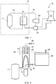
- a nuclear power plant is indicated generally at 10.
- the plant includes a reactor pressure vessel (RPV) 11 housing nuclear fuel, a primary fluid circuit 14, a heat exchanger which in this example is a steam generator 16, a secondary fluid circuit 18 and a turbine 20.
- the turbine 20 is housed within a turbine hall (or building or chamber) (not shown) and the reactor vessel 11 is housed within a reactor chamber 24 (or building or hall).
- the reactor chamber 24 is separated from the turbine hall by a containment barrier.
- the barrier may be made, for example, from concrete and/or steel.
- the primary fluid in the primary circuit 14 is heated by the thermal energy generated in the reactor pressure vessel 11.
- the primary fluid then flows to the steam generator 16, where it heats the secondary fluid, which in this example is water, to generate steam.
- the generated steam is then used to drive the turbine 20, thereby generating electricity.
- the secondary fluid flows to a condenser 19 where it is cooled using water from an ultimate heat sink 21.
- the ultimate heat sink may be a cooling tower, river, lake, or any other suitable supply of cooling water.
- the secondary circuit pumps may stop operating, meaning that the water in the secondary fluid circuit 18 will not continue to flow, causing a build-up of heat in the reactor pressure vessel 11. It is therefore desirable to provide a means for heat removal over extended periods of time from the immediate shut down state through to thermal roll-over of a plant without any intervention or power requirements.
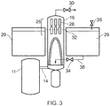
- FIG. 2 shows a part of the nuclear power plant which, as will be described in detail below, includes a local ultimate heatsink 29 for removing heat from the primary fluid circuit (and therefore from the reactor pressure vessel 11) in an emergency (e.g. during a power outage).
- the reactor is a close-coupled reactor which means that the steam generator 16 is closely coupled to the reactor pressure vessel 11.
- the steam generator 16 is adjacent to the reactor pressure vessel 11 and is both mechanically and fluidly connected to the reactor pressure vessel 11.
- Only one steam generator 16 is shown, it should be appreciated that a plurality of steam generators 16 may be provided.
- the entire assembly of the reactor pressure vessel 11 and the steam generator 16 is housed in the reactor chamber 24 and positioned proximal to a base of the reactor chamber 24.
- the steam generator 16 comprises two substantially horizontal arrays of steam separators 28, one located above the other in an upper region of the steam generator 16.
- the steam separators 28 are configured to dry the steam generated within the steam generator 16 such that water droplets are removed from vapour, thereby generating substantially dry steam.
- Substantially dry steam may be considered to be steam that contains less than 5% liquid water, or less than 4% liquid water, or less than 3% liquid water, or less than 2% liquid water, or less than 1% liquid water, or less than 0.5% liquid water, or less than 0.25% liquid water.
- the steam separators 28 therefore ensure that substantially dry steam is fed to the turbine 20. This may be highly desirable as wet steam can damage turbines and it carries less energy than dry steam.
- two rows of steam separators 28 are shown, it should be appreciated that any suitable number of separators could be used.
- the steam separators 28 define what is referred to in this specification as a steam drying zone 26 in the upper region of the steam generator 16.
- the steam drying zone 26 is the region of the steam generator 16 within which moisture droplets are removed from the wet steam by the steam separators 28 so as to generate substantially dry steam.
- the steam separators 28 are at least partly located within the steam drying zone 26.
- the steam generator 16 further comprises a depressurization valve 30 which is operable to depressurize the steam generator 16.
- the valve 30 may be operated by a motor or solenoid system, or via a remote control system, for example. In other arrangements, the valve 30 may comprise an electro-mechanical valve which may open automatically on loss of electrical power.
- the depressurization valve 30 can be operated to route the steam to a subsidiary location (i.e. a location or to equipment that is not the main turbine 20.
- the subsidiary location may be the reactor containment, the external atmosphere, a separate tank, an ultimate heat sink, or a local ultimate heat sink (which is described below).
- the nuclear power plant 10 further comprises a local ultimate heat sink (LUHS) in the form of a coolant reservoir 29.
- the local ultimate heat sink 29 is distinct from the ultimate heat sink 21 and is provided close (i.e. local) to the reactor pressure vessel 11.
- the coolant reservoir 29 is a water reservoir and contains a volume of water.
- other fluid coolants could be used.
- the coolant reservoir 29 can be used to draw heat away from the primary fluid circuit 14 in emergency conditions. Such an emergency condition may occur where the secondary fluid circuit 18 is not capable of drawing heat away from the primary fluid circuit 14. This could be because either fluid is not circulating in the secondary fluid circuit 18, or because the ultimate heat sink 21 is not appropriately cooling the secondary fluid.
- the coolant reservoir 29 is provided outside of the reactor chamber 24 such that there is a physical barrier (e.g. a containment barrier) between the reactor chamber 24 and the reservoir 29.
- a physical barrier e.g. a containment barrier
- the coolant reservoir 29 may be provided within the reactor chamber 24.
- the bottom of the reservoir 29 is fluidically connected to the bottom of the steam generator 16 by a feed conduit 38.
- the feed conduit 38 is provided with a valve 34, for example an electromechanical valve, which under emergency conditions opens (or can be opened) such that coolant within the reservoir 29 is supplied to the steam generator 16 under gravity.
- the upper region of the coolant reservoir 29 is also provided with a breather valve 36 which can be opened to provide fluid communication between the coolant reservoir 29 and the atmosphere (or external environment), thereby equalising the pressure between the inside and the outside of the reservoir 29. This may assist in the flow of coolant from the reservoir 29 to the steam generator 16 in emergency conditions.
- the coolant reservoir 29 is filled with coolant, which in this arrangement is water, to a fill level that ensures that when coolant is gravity-fed to the steam generator 16 (i.e. by opening valves 30, 34, 36) the coolant does not rise above a threshold level 32 defined by the steam drying zone 26.
- the threshold level 32 is at a position below the top of the steam separators 28 and above the bottom of the steam separators 28.
- the threshold level 32 is selected to ensure that, providing the coolant stays below the threshold level 32, the steam separators 28 appropriately function so as to dry the generated steam. This ensures that even under emergency conditions when the steam generator 16 is flooded with coolant from the reservoir 29, dry steam is generated.
- the coolant reservoir 29 is filled to a level that is at or below the threshold level 32. This ensures that when coolant 29 is fed to the steam generator 16 under gravity the coolant 29 does not exceed the threshold level 32.
- the coolant reservoir 29 could be filled above the threshold level 32, whilst still ensuring that under emergency conditions the coolant remains below the threshold level 32.
- the coolant reservoir 29 may be filled with coolant to a level above the threshold level 32 such that the volume of coolant in the coolant reservoir 29 above the threshold level 32 is no more than the volumetric capacity of the steam generator 16 below the threshold level 32.
- the steam generator 16 could be provided with an overflow that, under emergency conditions, prevents coolant from rising above the threshold level 32.
- valves 30, 36, 38 all open. This may be automatic, or an operator may have to open the valves in response to the detection of an emergency condition.
- one or more of the valves 30, 36, 38 may be electromechanical and configured such that in the case of a power outage the valves automatically open.
- Opening the depressurisation valve 30 causes the pressure within the steam generator 16 to drop, and also ensures that any steam generated is routed to a subsidiary location. Opening the breather valve 36 provides fluid communication between the coolant reservoir 29 and the atmosphere and therefore equalises the pressure. Opening the valve 34 causes the coolant (in this arrangement water) to gravity flow into the steam generator 16. The coolant, in the form of water, is turned into steam by the primary circuit 14, thereby removing heat from the primary circuit 14 and the reactor pressure vessel 11. Since the coolant remains below the threshold level 32, the steam separators 28 function appropriately to dry the steam (i.e. remove water droplets from the wet steam) such that the steam leaving the steam generator 16 is substantially dry steam.
- the steam leaving the steam generator 16 is substantially dry, more heat is removed from the steam generator 16 for the same volume of water. This may mean that less water is needed to achieve the same cooling than would be needed if the steam leaving the steam generator 16 was wet. Accordingly, it may be possible to provide a smaller coolant reservoir 29 (containing a smaller volume of water) in order to cool the reactor pressure vessel 11 for a set period of time (e.g. to thermal roll-over). Alternatively, of course, the same size reservoir 29 could be used to cool the reactor pressure vessel 11 for a longer period of time.
- the coolant reservoir 29 may be sized to provide the total heat sink requirements for decay heat removal over extended periods of time from the immediate shut down state through to thermal roll-over of a nuclear plant without any intervention or power requirements.
- the coolant reservoir 29 may be an annular coolant reservoir 29 that circumferentially surrounds the steam generator 16, reactor plant arrangement or reactor containment structure. Such an arrangement may allow the reservoir 29 to be appropriately sized, whilst keeping the level below the threshold level 32.
Landscapes
- Engineering & Computer Science (AREA)
- Physics & Mathematics (AREA)
- General Engineering & Computer Science (AREA)
- High Energy & Nuclear Physics (AREA)
- Thermal Sciences (AREA)
- Mechanical Engineering (AREA)
- Plasma & Fusion (AREA)
- Life Sciences & Earth Sciences (AREA)
- Sustainable Development (AREA)
- Sustainable Energy (AREA)
- Emergency Management (AREA)
- Business, Economics & Management (AREA)
- Chemical & Material Sciences (AREA)
- Combustion & Propulsion (AREA)
- Structure Of Emergency Protection For Nuclear Reactors (AREA)
Abstract
Description
- The present disclosure relates to nuclear power plants.
- A nuclear power plant typically includes a nuclear reactor, a primary circuit, a heat exchanger, a secondary circuit, and a turbine. The primary fluid in the primary circuit is heated by the nuclear reactor. The primary fluid flows to the heat exchanger, where it heats secondary fluid in the secondary circuit. The heated secondary fluid is then used to drive the turbine to generate electricity.
- It is important that the nuclear reactor and fuel does not overheat as this could result in catastrophic failure. As such, it is necessary to provide cooling to the reactor. Generally, cooling is provided in operation by the circulation of heat in the primary fluid (or coolant) of the primary circuit, exchanging that heat with the secondary cooling system via the heat exchanger (e.g. steam generator or boiler) and then exchanging this heat with an ultimate heat sink of the power station. The ultimate heat sink may be the sea, a cooling tower, or some other alternative heat sink.
- It is important that a nuclear power plant includes safety systems such that if there is a failure (e.g. no electricity) meaning that the usual cooling flow described above is not available, the reactor is prevented from overheating in its shutdown state, where the reactor will still be generating substantial heat in the form of decay heat.
- According to an aspect there is provided a nuclear power plant, comprising: a reactor pressure vessel; a steam generator arranged to generate steam utilising thermal energy generated within the reactor pressure vessel; a fluid circuit for transferring thermal energy from the reactor pressure vessel to the steam generator; and a coolant reservoir for storing coolant for supply to the steam generator under gravity in emergency conditions; wherein the steam generator comprises a steam drying zone comprising one or more steam separators configured to dry steam; and wherein the steam generator and coolant reservoir are configured such that when coolant is supplied from the coolant reservoir to the steam generator in emergency conditions the coolant stays below a threshold level defined by the steam drying zone.
- The threshold level may be set such that, provided that the coolant stays below the threshold level, the or each or at least some of the steam separators function to dry steam within the steam generator. The threshold level may be set such that, provided that the coolant in the secondary side of the steam generator stays below the threshold level, the or each or at least some of the steam separators function to dry steam within the steam generator. The threshold level may be defined by a lower limit of the steam drying zone. The steam drying zone may be defined as the region within which steam drying occurs, or the operable range of the or each steam separator. The or each steam separator may at least partially lie within the steam drying zone.
- The coolant reservoir may contain coolant such as water. The level of the coolant within the coolant reservoir may be at or below the threshold level. The coolant reservoir may be located inside a reactor containment. The coolant reservoir may circumferentially surround the steam generator, reactor arrangement or reactor containment structure.
- The coolant reservoir may be provided with a valve, such as a breather valve, operable to provide fluid communication between the coolant reservoir and the outside thereof. The power plant may further comprise a depressurisation valve operable to reduce the pressure within the steam generator. The depressurisation valve may be operable to route steam to a subsidiary location. The power plant may further comprise a feed conduit between the coolant reservoir and the steam generator. The feed conduit may be provided with a valve operable to allow fluid communication between the coolant reservoir and the steam generator.
- There is also disclosed a method of operating a nuclear power plant in accordance with any statement herein, the method comprising supplying coolant from the coolant reservoir to the steam generator under gravity, the coolant remaining below a threshold level defined by the steam drying zone.
- The method may further comprise opening a valve so as to provide fluid communication between the coolant reservoir and the outside thereof. The method may further comprise opening a depressurisation valve so as to reduce the pressure within the steam generator. Opening the depressurisation valve may route steam to a subsidiary location.
- The invention may comprise any combination of the features and/or limitations referred to herein, except combinations of such features as are mutually exclusive.
- Embodiments of the invention will now be described, by way of example, with reference to the accompanying drawings, in which:
-
Figure 1 schematically shows a nuclear power plant; -
Figure 2 schematically shows the reactor chamber ofFigure 1 ; and -
Figure 3 schematically shows a reactor chamber in accordance with an alternative arrangement. - Referring to
Figure 1 , a nuclear power plant is indicated generally at 10. The plant includes a reactor pressure vessel (RPV) 11 housing nuclear fuel, aprimary fluid circuit 14, a heat exchanger which in this example is asteam generator 16, asecondary fluid circuit 18 and aturbine 20. Theturbine 20 is housed within a turbine hall (or building or chamber) (not shown) and thereactor vessel 11 is housed within a reactor chamber 24 (or building or hall). Thereactor chamber 24 is separated from the turbine hall by a containment barrier. The barrier may be made, for example, from concrete and/or steel. - During normal operation of the
nuclear power plant 10, the primary fluid in theprimary circuit 14 is heated by the thermal energy generated in thereactor pressure vessel 11. The primary fluid then flows to thesteam generator 16, where it heats the secondary fluid, which in this example is water, to generate steam. The generated steam is then used to drive theturbine 20, thereby generating electricity. The secondary fluid flows to acondenser 19 where it is cooled using water from anultimate heat sink 21. The ultimate heat sink may be a cooling tower, river, lake, or any other suitable supply of cooling water. In emergency conditions, for example, if there is a power outage, the secondary circuit pumps may stop operating, meaning that the water in thesecondary fluid circuit 18 will not continue to flow, causing a build-up of heat in thereactor pressure vessel 11. It is therefore desirable to provide a means for heat removal over extended periods of time from the immediate shut down state through to thermal roll-over of a plant without any intervention or power requirements. -
Figure 2 shows a part of the nuclear power plant which, as will be described in detail below, includes a localultimate heatsink 29 for removing heat from the primary fluid circuit (and therefore from the reactor pressure vessel 11) in an emergency (e.g. during a power outage). As shown, in the present arrangement the reactor is a close-coupled reactor which means that thesteam generator 16 is closely coupled to thereactor pressure vessel 11. In particular, in this arrangement thesteam generator 16 is adjacent to thereactor pressure vessel 11 and is both mechanically and fluidly connected to thereactor pressure vessel 11. Although only onesteam generator 16 is shown, it should be appreciated that a plurality ofsteam generators 16 may be provided. The entire assembly of thereactor pressure vessel 11 and thesteam generator 16 is housed in thereactor chamber 24 and positioned proximal to a base of thereactor chamber 24. - As shown in
Figure 2 , thesteam generator 16 comprises two substantially horizontal arrays ofsteam separators 28, one located above the other in an upper region of thesteam generator 16. Thesteam separators 28 are configured to dry the steam generated within thesteam generator 16 such that water droplets are removed from vapour, thereby generating substantially dry steam. Substantially dry steam may be considered to be steam that contains less than 5% liquid water, or less than 4% liquid water, or less than 3% liquid water, or less than 2% liquid water, or less than 1% liquid water, or less than 0.5% liquid water, or less than 0.25% liquid water. Thesteam separators 28 therefore ensure that substantially dry steam is fed to theturbine 20. This may be highly desirable as wet steam can damage turbines and it carries less energy than dry steam. Although two rows ofsteam separators 28 are shown, it should be appreciated that any suitable number of separators could be used. - The
steam separators 28 define what is referred to in this specification as asteam drying zone 26 in the upper region of thesteam generator 16. Thesteam drying zone 26 is the region of thesteam generator 16 within which moisture droplets are removed from the wet steam by thesteam separators 28 so as to generate substantially dry steam. Thesteam separators 28 are at least partly located within thesteam drying zone 26. - The
steam generator 16 further comprises adepressurization valve 30 which is operable to depressurize thesteam generator 16. Thevalve 30 may be operated by a motor or solenoid system, or via a remote control system, for example. In other arrangements, thevalve 30 may comprise an electro-mechanical valve which may open automatically on loss of electrical power. Thedepressurization valve 30 can be operated to route the steam to a subsidiary location (i.e. a location or to equipment that is not themain turbine 20. The subsidiary location may be the reactor containment, the external atmosphere, a separate tank, an ultimate heat sink, or a local ultimate heat sink (which is described below). - The
nuclear power plant 10 further comprises a local ultimate heat sink (LUHS) in the form of acoolant reservoir 29. The localultimate heat sink 29 is distinct from theultimate heat sink 21 and is provided close (i.e. local) to thereactor pressure vessel 11. In this arrangement thecoolant reservoir 29 is a water reservoir and contains a volume of water. However, it should be appreciated that other fluid coolants could be used. As will be described in detail below, thecoolant reservoir 29 can be used to draw heat away from theprimary fluid circuit 14 in emergency conditions. Such an emergency condition may occur where thesecondary fluid circuit 18 is not capable of drawing heat away from theprimary fluid circuit 14. This could be because either fluid is not circulating in thesecondary fluid circuit 18, or because theultimate heat sink 21 is not appropriately cooling the secondary fluid. Such an emergency may occur when there is a power outage. In this arrangement thecoolant reservoir 29 is provided outside of thereactor chamber 24 such that there is a physical barrier (e.g. a containment barrier) between thereactor chamber 24 and thereservoir 29. However, in alternative arrangements thecoolant reservoir 29 may be provided within thereactor chamber 24. - The bottom of the
reservoir 29 is fluidically connected to the bottom of thesteam generator 16 by afeed conduit 38. Thefeed conduit 38 is provided with avalve 34, for example an electromechanical valve, which under emergency conditions opens (or can be opened) such that coolant within thereservoir 29 is supplied to thesteam generator 16 under gravity. The upper region of thecoolant reservoir 29 is also provided with abreather valve 36 which can be opened to provide fluid communication between thecoolant reservoir 29 and the atmosphere (or external environment), thereby equalising the pressure between the inside and the outside of thereservoir 29. This may assist in the flow of coolant from thereservoir 29 to thesteam generator 16 in emergency conditions. - The
coolant reservoir 29 is filled with coolant, which in this arrangement is water, to a fill level that ensures that when coolant is gravity-fed to the steam generator 16 (i.e. by openingvalves threshold level 32 defined by thesteam drying zone 26. In this arrangement thethreshold level 32 is at a position below the top of thesteam separators 28 and above the bottom of thesteam separators 28. Thethreshold level 32 is selected to ensure that, providing the coolant stays below thethreshold level 32, thesteam separators 28 appropriately function so as to dry the generated steam. This ensures that even under emergency conditions when thesteam generator 16 is flooded with coolant from thereservoir 29, dry steam is generated. - In this arrangement the
coolant reservoir 29 is filled to a level that is at or below thethreshold level 32. This ensures that whencoolant 29 is fed to thesteam generator 16 under gravity thecoolant 29 does not exceed thethreshold level 32. However, it should be appreciated that thecoolant reservoir 29 could be filled above thethreshold level 32, whilst still ensuring that under emergency conditions the coolant remains below thethreshold level 32. Specifically, thecoolant reservoir 29 may be filled with coolant to a level above thethreshold level 32 such that the volume of coolant in thecoolant reservoir 29 above thethreshold level 32 is no more than the volumetric capacity of thesteam generator 16 below thethreshold level 32. In an alternative arrangement thesteam generator 16 could be provided with an overflow that, under emergency conditions, prevents coolant from rising above thethreshold level 32. - In an emergency condition, for example if there is a power outage, it may no longer be possible to sufficiently cool the fluid within the
primary circuit 14. This may be because it is no longer possible to pump the fluid within thesecondary circuit 18 and/or because the secondary fluid may not be sufficiently cool. In such cases it is critical to ensure that thereactor pressure vessel 11 does not overheat. On detection of an emergency condition, thevalves valves depressurisation valve 30 causes the pressure within thesteam generator 16 to drop, and also ensures that any steam generated is routed to a subsidiary location. Opening thebreather valve 36 provides fluid communication between thecoolant reservoir 29 and the atmosphere and therefore equalises the pressure. Opening thevalve 34 causes the coolant (in this arrangement water) to gravity flow into thesteam generator 16. The coolant, in the form of water, is turned into steam by theprimary circuit 14, thereby removing heat from theprimary circuit 14 and thereactor pressure vessel 11. Since the coolant remains below thethreshold level 32, thesteam separators 28 function appropriately to dry the steam (i.e. remove water droplets from the wet steam) such that the steam leaving thesteam generator 16 is substantially dry steam. - As the steam leaving the
steam generator 16 is substantially dry, more heat is removed from thesteam generator 16 for the same volume of water. This may mean that less water is needed to achieve the same cooling than would be needed if the steam leaving thesteam generator 16 was wet. Accordingly, it may be possible to provide a smaller coolant reservoir 29 (containing a smaller volume of water) in order to cool thereactor pressure vessel 11 for a set period of time (e.g. to thermal roll-over). Alternatively, of course, thesame size reservoir 29 could be used to cool thereactor pressure vessel 11 for a longer period of time. Thecoolant reservoir 29 may be sized to provide the total heat sink requirements for decay heat removal over extended periods of time from the immediate shut down state through to thermal roll-over of a nuclear plant without any intervention or power requirements. - In an alternative arrangement shown in
Figure 3 , thecoolant reservoir 29 may be anannular coolant reservoir 29 that circumferentially surrounds thesteam generator 16, reactor plant arrangement or reactor containment structure. Such an arrangement may allow thereservoir 29 to be appropriately sized, whilst keeping the level below thethreshold level 32. - In the above described arrangement there is only a
single steam generator 16. However, it should be appreciated that there could bemultiple steam generators 16. Each could be provided with their own coolant reservoir 29 (or LUHS), or onecoolant reservoir 29 could supplymultiple steam generators 16. - Although the
steam generator 16 shown in a vertical steam generator, the arrangement described is equally applicable to a horizontal steam generator. - It will be understood that the invention is not limited to the embodiments above-described and various modifications and improvements can be made without departing from the concepts described herein. Except where mutually exclusive, any of the features may be employed separately or in combination with any other features and the disclosure extends to and includes all combinations and sub-combinations of one or more features described herein.
Claims (15)
- A nuclear power plant (10), comprising:a reactor pressure vessel (11);a steam generator (16) arranged to generate steam utilising thermal energy generated within the reactor pressure vessel;a fluid circuit (14) for transferring thermal energy from the reactor pressure vessel to the steam generator; anda coolant reservoir (29) for storing coolant for supply to the steam generator under gravity in emergency conditions;wherein the steam generator (16) comprises a steam drying zone (26) comprising one or more steam separators (28) configured to dry steam; andwherein the steam generator (16) and coolant reservoir (29) are configured such that when coolant is supplied from the coolant reservoir to the steam generator in emergency conditions the coolant stays below a threshold level (32) defined by the steam drying zone (26).
- A nuclear power plant according to claim 1, wherein the threshold level (32) is set such that, provided that the coolant stays below the threshold level, the or each steam separator (28) functions to dry steam within the steam generator (16).
- A nuclear power plant according to claim 1 or 2, wherein the threshold level (32) is defined by a lower limit of the steam drying zone (26).
- A nuclear power plant according to any preceding claim, wherein the or each steam separator (28) at least partially lies within the steam drying zone (26).
- A nuclear power plant according to any preceding claim, wherein the coolant reservoir (29) contains coolant.
- A nuclear power plant according to claim 5, wherein the level of the coolant within the coolant reservoir (29) is at or below the threshold level (32).
- A nuclear power plant according to any preceding claim, wherein the coolant reservoir (29) is located inside a reactor containment (24).
- A nuclear power plant according to any preceding claim, wherein the coolant reservoir (29) circumferentially surrounds the steam generator (16).
- A nuclear power plant according to any preceding claim, wherein the coolant reservoir (29) is provided with a valve (36) operable to provide fluid communication between the coolant reservoir and the outside thereof.
- A nuclear power plant according to any preceding claim, further comprising a depressurisation valve (30) operable to reduce the pressure within the steam generator (16).
- A nuclear power plant according to claim 10, wherein the depressurisation valve (30) is operable to route steam to a subsidiary location.
- A method of operating a nuclear power plant (10) in accordance with any preceding claim, the method comprising supplying coolant from the coolant reservoir (29) to the steam generator (16) under gravity, the coolant remaining below the threshold level (32) defined by the steam drying zone.
- A method according to claim 12, further comprising opening a valve (36) so as to provide fluid communication between the coolant reservoir and the outside thereof.
- A method according to claim 12 or 13, further comprising opening a depressurisation valve (30) so as to reduce the pressure within the steam generator.
- A method according to claim 14, wherein opening the depressurisation valve (30) routes steam to a subsidiary location.
Applications Claiming Priority (1)
| Application Number | Priority Date | Filing Date | Title |
|---|---|---|---|
| GB1719431.7A GB2568692B (en) | 2017-11-23 | 2017-11-23 | Nuclear power plants |
Publications (2)
| Publication Number | Publication Date |
|---|---|
| EP3492811A1 true EP3492811A1 (en) | 2019-06-05 |
| EP3492811B1 EP3492811B1 (en) | 2023-04-26 |
Family
ID=60950601
Family Applications (1)
| Application Number | Title | Priority Date | Filing Date |
|---|---|---|---|
| EP18205298.5A Active EP3492811B1 (en) | 2017-11-23 | 2018-11-09 | Nuclear power plants |
Country Status (7)
| Country | Link |
|---|---|
| US (1) | US20190164654A1 (en) |
| EP (1) | EP3492811B1 (en) |
| JP (1) | JP7199634B2 (en) |
| CA (1) | CA3025119A1 (en) |
| GB (1) | GB2568692B (en) |
| HU (1) | HUE062215T2 (en) |
| PL (1) | PL3492811T3 (en) |
Cited By (1)
| Publication number | Priority date | Publication date | Assignee | Title |
|---|---|---|---|---|
| WO2022186436A1 (en) * | 2021-03-04 | 2022-09-09 | Korea Atomic Energy Research Institute | Passive cooling system for nuclear reactor and method for operating the same |
Families Citing this family (1)
| Publication number | Priority date | Publication date | Assignee | Title |
|---|---|---|---|---|
| DE102022115375A1 (en) * | 2022-06-21 | 2023-12-21 | Franz Hofele | Thermal power plant and method for cooling a thermal power plant |
Citations (5)
| Publication number | Priority date | Publication date | Assignee | Title |
|---|---|---|---|---|
| EP0005898A1 (en) * | 1978-06-07 | 1979-12-12 | THE BABCOCK & WILCOX COMPANY | Method of operating a vapour generating system |
| EP0353867A1 (en) * | 1988-07-21 | 1990-02-07 | Rolls-Royce And Associates Limited | Full pressure passive emergency core cooling and residual heat removal system for water cooled nuclear reactors |
| US20150117586A1 (en) * | 2013-10-28 | 2015-04-30 | BABCOCK & WILCOX mPOWER, INC | Alternative safety function system for nuclear reactor |
| GB2535848A (en) * | 2014-11-19 | 2016-08-31 | China Nuclear Power Technology Res Inst Co Ltd | Secondary side passive waste heat removal system |
| GB2550352A (en) * | 2016-05-16 | 2017-11-22 | Rolls-Royce Power Eng Ltd | Power plant |
Family Cites Families (7)
| Publication number | Priority date | Publication date | Assignee | Title |
|---|---|---|---|---|
| DE2316066C2 (en) * | 1973-03-30 | 1982-05-27 | Siemens AG, 1000 Berlin und 8000 München | Nuclear reactor, especially pressurized water reactor |
| US4239596A (en) * | 1977-12-16 | 1980-12-16 | Combustion Engineering, Inc. | Passive residual heat removal system for nuclear power plant |
| US4654190A (en) * | 1984-04-05 | 1987-03-31 | Westinghouse Electric Corp. | Emergency feedwater system for steam generators of a nuclear power plant |
| FR2584228B1 (en) * | 1985-07-01 | 1987-12-24 | Framatome Sa | EMERGENCY COOLING DEVICE WITH INTRINSIC SAFETY OF A PRESSURE WATER NUCLEAR REACTOR. |
| JP2548838B2 (en) * | 1989-09-19 | 1996-10-30 | 三菱重工業株式会社 | Core collapse heat removal system for pressurized water reactor |
| DE4126630A1 (en) * | 1991-08-12 | 1993-02-18 | Siemens Ag | SECOND-SIDED HEAT EXHAUST SYSTEM FOR PRESSURE WATER CORE REACTORS |
| JP5055165B2 (en) * | 2008-02-29 | 2012-10-24 | 三菱重工業株式会社 | Steam generator |
-
2017
- 2017-11-23 GB GB1719431.7A patent/GB2568692B/en not_active Expired - Fee Related
-
2018
- 2018-11-08 US US16/184,606 patent/US20190164654A1/en not_active Abandoned
- 2018-11-09 PL PL18205298.5T patent/PL3492811T3/en unknown
- 2018-11-09 HU HUE18205298A patent/HUE062215T2/en unknown
- 2018-11-09 EP EP18205298.5A patent/EP3492811B1/en active Active
- 2018-11-22 JP JP2018219118A patent/JP7199634B2/en active Active
- 2018-11-23 CA CA3025119A patent/CA3025119A1/en active Pending
Patent Citations (5)
| Publication number | Priority date | Publication date | Assignee | Title |
|---|---|---|---|---|
| EP0005898A1 (en) * | 1978-06-07 | 1979-12-12 | THE BABCOCK & WILCOX COMPANY | Method of operating a vapour generating system |
| EP0353867A1 (en) * | 1988-07-21 | 1990-02-07 | Rolls-Royce And Associates Limited | Full pressure passive emergency core cooling and residual heat removal system for water cooled nuclear reactors |
| US20150117586A1 (en) * | 2013-10-28 | 2015-04-30 | BABCOCK & WILCOX mPOWER, INC | Alternative safety function system for nuclear reactor |
| GB2535848A (en) * | 2014-11-19 | 2016-08-31 | China Nuclear Power Technology Res Inst Co Ltd | Secondary side passive waste heat removal system |
| GB2550352A (en) * | 2016-05-16 | 2017-11-22 | Rolls-Royce Power Eng Ltd | Power plant |
Cited By (1)
| Publication number | Priority date | Publication date | Assignee | Title |
|---|---|---|---|---|
| WO2022186436A1 (en) * | 2021-03-04 | 2022-09-09 | Korea Atomic Energy Research Institute | Passive cooling system for nuclear reactor and method for operating the same |
Also Published As
| Publication number | Publication date |
|---|---|
| GB2568692B (en) | 2020-01-22 |
| PL3492811T3 (en) | 2023-09-11 |
| HUE062215T2 (en) | 2023-10-28 |
| US20190164654A1 (en) | 2019-05-30 |
| EP3492811B1 (en) | 2023-04-26 |
| GB2568692A (en) | 2019-05-29 |
| JP2019095450A (en) | 2019-06-20 |
| JP7199634B2 (en) | 2023-01-06 |
| CA3025119A1 (en) | 2019-05-23 |
| GB201719431D0 (en) | 2018-01-10 |
Similar Documents
| Publication | Publication Date | Title |
|---|---|---|
| KR101463440B1 (en) | Passive safety system and nuclear power plant having the same | |
| JP7744455B2 (en) | A highly simplified emergency condenser for a boiling water reactor. | |
| KR101229954B1 (en) | Passive cooling system for nuclear power plant | |
| EP0389231A2 (en) | Containment heat removal system | |
| KR101940197B1 (en) | Heat removal system and method for use with a nuclear reactor | |
| KR101242746B1 (en) | Integrated passive safety system outside containment for nuclear power plants | |
| US9947421B2 (en) | Nuclear reactor with liquid metal coolant | |
| JP6305936B2 (en) | Underwater power generation module | |
| KR20100072306A (en) | Nuclear reactor with improved cooling in an accident situation | |
| KR102243711B1 (en) | Nuclear reactor long-term cooling system and nuclear plant having the same | |
| US9194629B2 (en) | Condensation chamber cooling system | |
| JP6305935B2 (en) | Diving energy generation module | |
| US11915836B2 (en) | Cooling system in a nuclear plant | |
| CN112700893A (en) | Waste heat discharge system and method and nuclear power system | |
| CN204991158U (en) | A passive gravity safety injection system for nuclear power plants | |
| EP3492811B1 (en) | Nuclear power plants | |
| JP6359318B2 (en) | Static reactor containment cooling system and nuclear power plant | |
| CN210837199U (en) | Waste heat discharge system and nuclear power system | |
| JP5279325B2 (en) | Hybrid safety system for boiling water reactors | |
| JP6203196B2 (en) | Power generation module | |
| KR102115044B1 (en) | Underwater electricity generation module | |
| JP6305937B2 (en) | Submersible or underwater power generation module | |
| KR102583804B1 (en) | Small modular Reactor including the passive safety system | |
| KR20170011416A (en) | Passive Safety System of Nuclear Power generation system | |
| RU2650504C2 (en) | Emergency nuclear reactor cooling system |
Legal Events
| Date | Code | Title | Description |
|---|---|---|---|
| PUAI | Public reference made under article 153(3) epc to a published international application that has entered the european phase |
Free format text: ORIGINAL CODE: 0009012 |
|
| STAA | Information on the status of an ep patent application or granted ep patent |
Free format text: STATUS: THE APPLICATION HAS BEEN PUBLISHED |
|
| AK | Designated contracting states |
Kind code of ref document: A1 Designated state(s): AL AT BE BG CH CY CZ DE DK EE ES FI FR GB GR HR HU IE IS IT LI LT LU LV MC MK MT NL NO PL PT RO RS SE SI SK SM TR |
|
| AX | Request for extension of the european patent |
Extension state: BA ME |
|
| STAA | Information on the status of an ep patent application or granted ep patent |
Free format text: STATUS: REQUEST FOR EXAMINATION WAS MADE |
|
| 17P | Request for examination filed |
Effective date: 20191001 |
|
| RBV | Designated contracting states (corrected) |
Designated state(s): AL AT BE BG CH CY CZ DE DK EE ES FI FR GB GR HR HU IE IS IT LI LT LU LV MC MK MT NL NO PL PT RO RS SE SI SK SM TR |
|
| RAP1 | Party data changed (applicant data changed or rights of an application transferred) |
Owner name: ROLLS-ROYCE PLC |
|
| RIC1 | Information provided on ipc code assigned before grant |
Ipc: G21D 3/04 20060101ALI20220510BHEP Ipc: G21C 15/18 20060101ALI20220510BHEP Ipc: F22B 37/26 20060101ALI20220510BHEP Ipc: F22B 35/00 20060101ALI20220510BHEP Ipc: F22B 1/12 20060101ALI20220510BHEP Ipc: F22B 1/02 20060101AFI20220510BHEP |
|
| GRAP | Despatch of communication of intention to grant a patent |
Free format text: ORIGINAL CODE: EPIDOSNIGR1 |
|
| STAA | Information on the status of an ep patent application or granted ep patent |
Free format text: STATUS: GRANT OF PATENT IS INTENDED |
|
| INTG | Intention to grant announced |
Effective date: 20220627 |
|
| RAP1 | Party data changed (applicant data changed or rights of an application transferred) |
Owner name: ROLLS-ROYCE SMR LIMITED |
|
| GRAJ | Information related to disapproval of communication of intention to grant by the applicant or resumption of examination proceedings by the epo deleted |
Free format text: ORIGINAL CODE: EPIDOSDIGR1 |
|
| STAA | Information on the status of an ep patent application or granted ep patent |
Free format text: STATUS: REQUEST FOR EXAMINATION WAS MADE |
|
| INTC | Intention to grant announced (deleted) | ||
| GRAP | Despatch of communication of intention to grant a patent |
Free format text: ORIGINAL CODE: EPIDOSNIGR1 |
|
| STAA | Information on the status of an ep patent application or granted ep patent |
Free format text: STATUS: GRANT OF PATENT IS INTENDED |
|
| INTG | Intention to grant announced |
Effective date: 20230105 |
|
| GRAS | Grant fee paid |
Free format text: ORIGINAL CODE: EPIDOSNIGR3 |
|
| GRAA | (expected) grant |
Free format text: ORIGINAL CODE: 0009210 |
|
| STAA | Information on the status of an ep patent application or granted ep patent |
Free format text: STATUS: THE PATENT HAS BEEN GRANTED |
|
| AK | Designated contracting states |
Kind code of ref document: B1 Designated state(s): AL AT BE BG CH CY CZ DE DK EE ES FI FR GB GR HR HU IE IS IT LI LT LU LV MC MK MT NL NO PL PT RO RS SE SI SK SM TR |
|
| REG | Reference to a national code |
Ref country code: GB Ref legal event code: FG4D |
|
| REG | Reference to a national code |
Ref country code: CH Ref legal event code: EP |
|
| REG | Reference to a national code |
Ref country code: DE Ref legal event code: R096 Ref document number: 602018048834 Country of ref document: DE |
|
| REG | Reference to a national code |
Ref country code: AT Ref legal event code: REF Ref document number: 1563074 Country of ref document: AT Kind code of ref document: T Effective date: 20230515 |
|
| REG | Reference to a national code |
Ref country code: IE Ref legal event code: FG4D |
|
| REG | Reference to a national code |
Ref country code: NO Ref legal event code: T2 Effective date: 20230426 |
|
| REG | Reference to a national code |
Ref country code: LT Ref legal event code: MG9D |
|
| REG | Reference to a national code |
Ref country code: NL Ref legal event code: MP Effective date: 20230426 |
|
| REG | Reference to a national code |
Ref country code: AT Ref legal event code: MK05 Ref document number: 1563074 Country of ref document: AT Kind code of ref document: T Effective date: 20230426 |
|
| PG25 | Lapsed in a contracting state [announced via postgrant information from national office to epo] |
Ref country code: NL Free format text: LAPSE BECAUSE OF FAILURE TO SUBMIT A TRANSLATION OF THE DESCRIPTION OR TO PAY THE FEE WITHIN THE PRESCRIBED TIME-LIMIT Effective date: 20230426 |
|
| REG | Reference to a national code |
Ref country code: HU Ref legal event code: AG4A Ref document number: E062215 Country of ref document: HU |
|
| PG25 | Lapsed in a contracting state [announced via postgrant information from national office to epo] |
Ref country code: SE Free format text: LAPSE BECAUSE OF FAILURE TO SUBMIT A TRANSLATION OF THE DESCRIPTION OR TO PAY THE FEE WITHIN THE PRESCRIBED TIME-LIMIT Effective date: 20230426 Ref country code: PT Free format text: LAPSE BECAUSE OF FAILURE TO SUBMIT A TRANSLATION OF THE DESCRIPTION OR TO PAY THE FEE WITHIN THE PRESCRIBED TIME-LIMIT Effective date: 20230828 Ref country code: ES Free format text: LAPSE BECAUSE OF FAILURE TO SUBMIT A TRANSLATION OF THE DESCRIPTION OR TO PAY THE FEE WITHIN THE PRESCRIBED TIME-LIMIT Effective date: 20230426 Ref country code: AT Free format text: LAPSE BECAUSE OF FAILURE TO SUBMIT A TRANSLATION OF THE DESCRIPTION OR TO PAY THE FEE WITHIN THE PRESCRIBED TIME-LIMIT Effective date: 20230426 |
|
| PG25 | Lapsed in a contracting state [announced via postgrant information from national office to epo] |
Ref country code: RS Free format text: LAPSE BECAUSE OF FAILURE TO SUBMIT A TRANSLATION OF THE DESCRIPTION OR TO PAY THE FEE WITHIN THE PRESCRIBED TIME-LIMIT Effective date: 20230426 Ref country code: LV Free format text: LAPSE BECAUSE OF FAILURE TO SUBMIT A TRANSLATION OF THE DESCRIPTION OR TO PAY THE FEE WITHIN THE PRESCRIBED TIME-LIMIT Effective date: 20230426 Ref country code: LT Free format text: LAPSE BECAUSE OF FAILURE TO SUBMIT A TRANSLATION OF THE DESCRIPTION OR TO PAY THE FEE WITHIN THE PRESCRIBED TIME-LIMIT Effective date: 20230426 Ref country code: IS Free format text: LAPSE BECAUSE OF FAILURE TO SUBMIT A TRANSLATION OF THE DESCRIPTION OR TO PAY THE FEE WITHIN THE PRESCRIBED TIME-LIMIT Effective date: 20230826 Ref country code: HR Free format text: LAPSE BECAUSE OF FAILURE TO SUBMIT A TRANSLATION OF THE DESCRIPTION OR TO PAY THE FEE WITHIN THE PRESCRIBED TIME-LIMIT Effective date: 20230426 Ref country code: GR Free format text: LAPSE BECAUSE OF FAILURE TO SUBMIT A TRANSLATION OF THE DESCRIPTION OR TO PAY THE FEE WITHIN THE PRESCRIBED TIME-LIMIT Effective date: 20230727 |
|
| PG25 | Lapsed in a contracting state [announced via postgrant information from national office to epo] |
Ref country code: FI Free format text: LAPSE BECAUSE OF FAILURE TO SUBMIT A TRANSLATION OF THE DESCRIPTION OR TO PAY THE FEE WITHIN THE PRESCRIBED TIME-LIMIT Effective date: 20230426 |
|
| PG25 | Lapsed in a contracting state [announced via postgrant information from national office to epo] |
Ref country code: SK Free format text: LAPSE BECAUSE OF FAILURE TO SUBMIT A TRANSLATION OF THE DESCRIPTION OR TO PAY THE FEE WITHIN THE PRESCRIBED TIME-LIMIT Effective date: 20230426 |
|
| REG | Reference to a national code |
Ref country code: DE Ref legal event code: R097 Ref document number: 602018048834 Country of ref document: DE |
|
| PG25 | Lapsed in a contracting state [announced via postgrant information from national office to epo] |
Ref country code: SM Free format text: LAPSE BECAUSE OF FAILURE TO SUBMIT A TRANSLATION OF THE DESCRIPTION OR TO PAY THE FEE WITHIN THE PRESCRIBED TIME-LIMIT Effective date: 20230426 Ref country code: SK Free format text: LAPSE BECAUSE OF FAILURE TO SUBMIT A TRANSLATION OF THE DESCRIPTION OR TO PAY THE FEE WITHIN THE PRESCRIBED TIME-LIMIT Effective date: 20230426 Ref country code: RO Free format text: LAPSE BECAUSE OF FAILURE TO SUBMIT A TRANSLATION OF THE DESCRIPTION OR TO PAY THE FEE WITHIN THE PRESCRIBED TIME-LIMIT Effective date: 20230426 Ref country code: EE Free format text: LAPSE BECAUSE OF FAILURE TO SUBMIT A TRANSLATION OF THE DESCRIPTION OR TO PAY THE FEE WITHIN THE PRESCRIBED TIME-LIMIT Effective date: 20230426 Ref country code: DK Free format text: LAPSE BECAUSE OF FAILURE TO SUBMIT A TRANSLATION OF THE DESCRIPTION OR TO PAY THE FEE WITHIN THE PRESCRIBED TIME-LIMIT Effective date: 20230426 |
|
| PLBE | No opposition filed within time limit |
Free format text: ORIGINAL CODE: 0009261 |
|
| STAA | Information on the status of an ep patent application or granted ep patent |
Free format text: STATUS: NO OPPOSITION FILED WITHIN TIME LIMIT |
|
| 26N | No opposition filed |
Effective date: 20240129 |
|
| PG25 | Lapsed in a contracting state [announced via postgrant information from national office to epo] |
Ref country code: SI Free format text: LAPSE BECAUSE OF FAILURE TO SUBMIT A TRANSLATION OF THE DESCRIPTION OR TO PAY THE FEE WITHIN THE PRESCRIBED TIME-LIMIT Effective date: 20230426 |
|
| PG25 | Lapsed in a contracting state [announced via postgrant information from national office to epo] |
Ref country code: SI Free format text: LAPSE BECAUSE OF FAILURE TO SUBMIT A TRANSLATION OF THE DESCRIPTION OR TO PAY THE FEE WITHIN THE PRESCRIBED TIME-LIMIT Effective date: 20230426 Ref country code: IT Free format text: LAPSE BECAUSE OF FAILURE TO SUBMIT A TRANSLATION OF THE DESCRIPTION OR TO PAY THE FEE WITHIN THE PRESCRIBED TIME-LIMIT Effective date: 20230426 |
|
| REG | Reference to a national code |
Ref country code: CH Ref legal event code: PL |
|
| PG25 | Lapsed in a contracting state [announced via postgrant information from national office to epo] |
Ref country code: MC Free format text: LAPSE BECAUSE OF FAILURE TO SUBMIT A TRANSLATION OF THE DESCRIPTION OR TO PAY THE FEE WITHIN THE PRESCRIBED TIME-LIMIT Effective date: 20230426 |
|
| PG25 | Lapsed in a contracting state [announced via postgrant information from national office to epo] |
Ref country code: LU Free format text: LAPSE BECAUSE OF NON-PAYMENT OF DUE FEES Effective date: 20231109 |
|
| PG25 | Lapsed in a contracting state [announced via postgrant information from national office to epo] |
Ref country code: CH Free format text: LAPSE BECAUSE OF NON-PAYMENT OF DUE FEES Effective date: 20231130 |
|
| PG25 | Lapsed in a contracting state [announced via postgrant information from national office to epo] |
Ref country code: MC Free format text: LAPSE BECAUSE OF FAILURE TO SUBMIT A TRANSLATION OF THE DESCRIPTION OR TO PAY THE FEE WITHIN THE PRESCRIBED TIME-LIMIT Effective date: 20230426 Ref country code: LU Free format text: LAPSE BECAUSE OF NON-PAYMENT OF DUE FEES Effective date: 20231109 Ref country code: CH Free format text: LAPSE BECAUSE OF NON-PAYMENT OF DUE FEES Effective date: 20231130 |
|
| REG | Reference to a national code |
Ref country code: BE Ref legal event code: MM Effective date: 20231130 |
|
| REG | Reference to a national code |
Ref country code: IE Ref legal event code: MM4A |
|
| PG25 | Lapsed in a contracting state [announced via postgrant information from national office to epo] |
Ref country code: IE Free format text: LAPSE BECAUSE OF NON-PAYMENT OF DUE FEES Effective date: 20231109 |
|
| PG25 | Lapsed in a contracting state [announced via postgrant information from national office to epo] |
Ref country code: BE Free format text: LAPSE BECAUSE OF NON-PAYMENT OF DUE FEES Effective date: 20231130 |
|
| PG25 | Lapsed in a contracting state [announced via postgrant information from national office to epo] |
Ref country code: IE Free format text: LAPSE BECAUSE OF NON-PAYMENT OF DUE FEES Effective date: 20231109 Ref country code: BE Free format text: LAPSE BECAUSE OF NON-PAYMENT OF DUE FEES Effective date: 20231130 |
|
| PG25 | Lapsed in a contracting state [announced via postgrant information from national office to epo] |
Ref country code: BG Free format text: LAPSE BECAUSE OF FAILURE TO SUBMIT A TRANSLATION OF THE DESCRIPTION OR TO PAY THE FEE WITHIN THE PRESCRIBED TIME-LIMIT Effective date: 20230426 |
|
| PG25 | Lapsed in a contracting state [announced via postgrant information from national office to epo] |
Ref country code: BG Free format text: LAPSE BECAUSE OF FAILURE TO SUBMIT A TRANSLATION OF THE DESCRIPTION OR TO PAY THE FEE WITHIN THE PRESCRIBED TIME-LIMIT Effective date: 20230426 |
|
| PG25 | Lapsed in a contracting state [announced via postgrant information from national office to epo] |
Ref country code: CY Free format text: LAPSE BECAUSE OF FAILURE TO SUBMIT A TRANSLATION OF THE DESCRIPTION OR TO PAY THE FEE WITHIN THE PRESCRIBED TIME-LIMIT; INVALID AB INITIO Effective date: 20181109 |
|
| PGFP | Annual fee paid to national office [announced via postgrant information from national office to epo] |
Ref country code: PL Payment date: 20250716 Year of fee payment: 8 |
|
| PGFP | Annual fee paid to national office [announced via postgrant information from national office to epo] |
Ref country code: CZ Payment date: 20250717 Year of fee payment: 8 |
|
| PGFP | Annual fee paid to national office [announced via postgrant information from national office to epo] |
Ref country code: HU Payment date: 20251027 Year of fee payment: 8 |
|
| PGFP | Annual fee paid to national office [announced via postgrant information from national office to epo] |
Ref country code: DE Payment date: 20251021 Year of fee payment: 8 |
|
| PGFP | Annual fee paid to national office [announced via postgrant information from national office to epo] |
Ref country code: GB Payment date: 20251020 Year of fee payment: 8 |
|
| PGFP | Annual fee paid to national office [announced via postgrant information from national office to epo] |
Ref country code: NO Payment date: 20251023 Year of fee payment: 8 |
|
| PGFP | Annual fee paid to national office [announced via postgrant information from national office to epo] |
Ref country code: FR Payment date: 20251021 Year of fee payment: 8 |
|
| PGFP | Annual fee paid to national office [announced via postgrant information from national office to epo] |
Ref country code: TR Payment date: 20251009 Year of fee payment: 8 |