EP3492759A1 - Tapered roller bearing for automobile - Google Patents
Tapered roller bearing for automobile Download PDFInfo
- Publication number
- EP3492759A1 EP3492759A1 EP17833960.2A EP17833960A EP3492759A1 EP 3492759 A1 EP3492759 A1 EP 3492759A1 EP 17833960 A EP17833960 A EP 17833960A EP 3492759 A1 EP3492759 A1 EP 3492759A1
- Authority
- EP
- European Patent Office
- Prior art keywords
- crowning
- tapered roller
- tapered
- roller bearing
- automobile
- Prior art date
- Legal status (The legal status is an assumption and is not a legal conclusion. Google has not performed a legal analysis and makes no representation as to the accuracy of the status listed.)
- Granted
Links
Images


Classifications
-
- F—MECHANICAL ENGINEERING; LIGHTING; HEATING; WEAPONS; BLASTING
- F16—ENGINEERING ELEMENTS AND UNITS; GENERAL MEASURES FOR PRODUCING AND MAINTAINING EFFECTIVE FUNCTIONING OF MACHINES OR INSTALLATIONS; THERMAL INSULATION IN GENERAL
- F16C—SHAFTS; FLEXIBLE SHAFTS; ELEMENTS OR CRANKSHAFT MECHANISMS; ROTARY BODIES OTHER THAN GEARING ELEMENTS; BEARINGS
- F16C19/00—Bearings with rolling contact, for exclusively rotary movement
- F16C19/22—Bearings with rolling contact, for exclusively rotary movement with bearing rollers essentially of the same size in one or more circular rows, e.g. needle bearings
- F16C19/34—Bearings with rolling contact, for exclusively rotary movement with bearing rollers essentially of the same size in one or more circular rows, e.g. needle bearings for both radial and axial load
- F16C19/36—Bearings with rolling contact, for exclusively rotary movement with bearing rollers essentially of the same size in one or more circular rows, e.g. needle bearings for both radial and axial load with a single row of rollers
- F16C19/364—Bearings with rolling contact, for exclusively rotary movement with bearing rollers essentially of the same size in one or more circular rows, e.g. needle bearings for both radial and axial load with a single row of rollers with tapered rollers, i.e. rollers having essentially the shape of a truncated cone
-
- F—MECHANICAL ENGINEERING; LIGHTING; HEATING; WEAPONS; BLASTING
- F16—ENGINEERING ELEMENTS AND UNITS; GENERAL MEASURES FOR PRODUCING AND MAINTAINING EFFECTIVE FUNCTIONING OF MACHINES OR INSTALLATIONS; THERMAL INSULATION IN GENERAL
- F16C—SHAFTS; FLEXIBLE SHAFTS; ELEMENTS OR CRANKSHAFT MECHANISMS; ROTARY BODIES OTHER THAN GEARING ELEMENTS; BEARINGS
- F16C19/00—Bearings with rolling contact, for exclusively rotary movement
- F16C19/22—Bearings with rolling contact, for exclusively rotary movement with bearing rollers essentially of the same size in one or more circular rows, e.g. needle bearings
- F16C19/34—Bearings with rolling contact, for exclusively rotary movement with bearing rollers essentially of the same size in one or more circular rows, e.g. needle bearings for both radial and axial load
- F16C19/38—Bearings with rolling contact, for exclusively rotary movement with bearing rollers essentially of the same size in one or more circular rows, e.g. needle bearings for both radial and axial load with two or more rows of rollers
-
- F—MECHANICAL ENGINEERING; LIGHTING; HEATING; WEAPONS; BLASTING
- F16—ENGINEERING ELEMENTS AND UNITS; GENERAL MEASURES FOR PRODUCING AND MAINTAINING EFFECTIVE FUNCTIONING OF MACHINES OR INSTALLATIONS; THERMAL INSULATION IN GENERAL
- F16C—SHAFTS; FLEXIBLE SHAFTS; ELEMENTS OR CRANKSHAFT MECHANISMS; ROTARY BODIES OTHER THAN GEARING ELEMENTS; BEARINGS
- F16C33/00—Parts of bearings; Special methods for making bearings or parts thereof
- F16C33/30—Parts of ball or roller bearings
- F16C33/34—Rollers; Needles
- F16C33/36—Rollers; Needles with bearing-surfaces other than cylindrical, e.g. tapered; with grooves in the bearing surfaces
-
- F—MECHANICAL ENGINEERING; LIGHTING; HEATING; WEAPONS; BLASTING
- F16—ENGINEERING ELEMENTS AND UNITS; GENERAL MEASURES FOR PRODUCING AND MAINTAINING EFFECTIVE FUNCTIONING OF MACHINES OR INSTALLATIONS; THERMAL INSULATION IN GENERAL
- F16C—SHAFTS; FLEXIBLE SHAFTS; ELEMENTS OR CRANKSHAFT MECHANISMS; ROTARY BODIES OTHER THAN GEARING ELEMENTS; BEARINGS
- F16C33/00—Parts of bearings; Special methods for making bearings or parts thereof
- F16C33/30—Parts of ball or roller bearings
- F16C33/34—Rollers; Needles
- F16C33/36—Rollers; Needles with bearing-surfaces other than cylindrical, e.g. tapered; with grooves in the bearing surfaces
- F16C33/366—Tapered rollers, i.e. rollers generally shaped as truncated cones
-
- F—MECHANICAL ENGINEERING; LIGHTING; HEATING; WEAPONS; BLASTING
- F16—ENGINEERING ELEMENTS AND UNITS; GENERAL MEASURES FOR PRODUCING AND MAINTAINING EFFECTIVE FUNCTIONING OF MACHINES OR INSTALLATIONS; THERMAL INSULATION IN GENERAL
- F16C—SHAFTS; FLEXIBLE SHAFTS; ELEMENTS OR CRANKSHAFT MECHANISMS; ROTARY BODIES OTHER THAN GEARING ELEMENTS; BEARINGS
- F16C33/00—Parts of bearings; Special methods for making bearings or parts thereof
- F16C33/30—Parts of ball or roller bearings
- F16C33/58—Raceways; Race rings
- F16C33/583—Details of specific parts of races
- F16C33/585—Details of specific parts of races of raceways, e.g. ribs to guide the rollers
-
- F—MECHANICAL ENGINEERING; LIGHTING; HEATING; WEAPONS; BLASTING
- F16—ENGINEERING ELEMENTS AND UNITS; GENERAL MEASURES FOR PRODUCING AND MAINTAINING EFFECTIVE FUNCTIONING OF MACHINES OR INSTALLATIONS; THERMAL INSULATION IN GENERAL
- F16C—SHAFTS; FLEXIBLE SHAFTS; ELEMENTS OR CRANKSHAFT MECHANISMS; ROTARY BODIES OTHER THAN GEARING ELEMENTS; BEARINGS
- F16C33/00—Parts of bearings; Special methods for making bearings or parts thereof
- F16C33/30—Parts of ball or roller bearings
- F16C33/58—Raceways; Race rings
- F16C33/62—Selection of substances
-
- F—MECHANICAL ENGINEERING; LIGHTING; HEATING; WEAPONS; BLASTING
- F16—ENGINEERING ELEMENTS AND UNITS; GENERAL MEASURES FOR PRODUCING AND MAINTAINING EFFECTIVE FUNCTIONING OF MACHINES OR INSTALLATIONS; THERMAL INSULATION IN GENERAL
- F16C—SHAFTS; FLEXIBLE SHAFTS; ELEMENTS OR CRANKSHAFT MECHANISMS; ROTARY BODIES OTHER THAN GEARING ELEMENTS; BEARINGS
- F16C33/00—Parts of bearings; Special methods for making bearings or parts thereof
- F16C33/30—Parts of ball or roller bearings
- F16C33/58—Raceways; Race rings
- F16C33/64—Special methods of manufacture
-
- F—MECHANICAL ENGINEERING; LIGHTING; HEATING; WEAPONS; BLASTING
- F16—ENGINEERING ELEMENTS AND UNITS; GENERAL MEASURES FOR PRODUCING AND MAINTAINING EFFECTIVE FUNCTIONING OF MACHINES OR INSTALLATIONS; THERMAL INSULATION IN GENERAL
- F16C—SHAFTS; FLEXIBLE SHAFTS; ELEMENTS OR CRANKSHAFT MECHANISMS; ROTARY BODIES OTHER THAN GEARING ELEMENTS; BEARINGS
- F16C19/00—Bearings with rolling contact, for exclusively rotary movement
- F16C19/22—Bearings with rolling contact, for exclusively rotary movement with bearing rollers essentially of the same size in one or more circular rows, e.g. needle bearings
- F16C19/34—Bearings with rolling contact, for exclusively rotary movement with bearing rollers essentially of the same size in one or more circular rows, e.g. needle bearings for both radial and axial load
- F16C19/38—Bearings with rolling contact, for exclusively rotary movement with bearing rollers essentially of the same size in one or more circular rows, e.g. needle bearings for both radial and axial load with two or more rows of rollers
- F16C19/383—Bearings with rolling contact, for exclusively rotary movement with bearing rollers essentially of the same size in one or more circular rows, e.g. needle bearings for both radial and axial load with two or more rows of rollers with tapered rollers, i.e. rollers having essentially the shape of a truncated cone
- F16C19/385—Bearings with rolling contact, for exclusively rotary movement with bearing rollers essentially of the same size in one or more circular rows, e.g. needle bearings for both radial and axial load with two or more rows of rollers with tapered rollers, i.e. rollers having essentially the shape of a truncated cone with two rows, i.e. double-row tapered roller bearings
-
- F—MECHANICAL ENGINEERING; LIGHTING; HEATING; WEAPONS; BLASTING
- F16—ENGINEERING ELEMENTS AND UNITS; GENERAL MEASURES FOR PRODUCING AND MAINTAINING EFFECTIVE FUNCTIONING OF MACHINES OR INSTALLATIONS; THERMAL INSULATION IN GENERAL
- F16C—SHAFTS; FLEXIBLE SHAFTS; ELEMENTS OR CRANKSHAFT MECHANISMS; ROTARY BODIES OTHER THAN GEARING ELEMENTS; BEARINGS
- F16C2204/00—Metallic materials; Alloys
- F16C2204/60—Ferrous alloys, e.g. steel alloys
- F16C2204/66—High carbon steel, i.e. carbon content above 0.8 wt%, e.g. through-hardenable steel
-
- F—MECHANICAL ENGINEERING; LIGHTING; HEATING; WEAPONS; BLASTING
- F16—ENGINEERING ELEMENTS AND UNITS; GENERAL MEASURES FOR PRODUCING AND MAINTAINING EFFECTIVE FUNCTIONING OF MACHINES OR INSTALLATIONS; THERMAL INSULATION IN GENERAL
- F16C—SHAFTS; FLEXIBLE SHAFTS; ELEMENTS OR CRANKSHAFT MECHANISMS; ROTARY BODIES OTHER THAN GEARING ELEMENTS; BEARINGS
- F16C2204/00—Metallic materials; Alloys
- F16C2204/60—Ferrous alloys, e.g. steel alloys
- F16C2204/70—Ferrous alloys, e.g. steel alloys with chromium as the next major constituent
-
- F—MECHANICAL ENGINEERING; LIGHTING; HEATING; WEAPONS; BLASTING
- F16—ENGINEERING ELEMENTS AND UNITS; GENERAL MEASURES FOR PRODUCING AND MAINTAINING EFFECTIVE FUNCTIONING OF MACHINES OR INSTALLATIONS; THERMAL INSULATION IN GENERAL
- F16C—SHAFTS; FLEXIBLE SHAFTS; ELEMENTS OR CRANKSHAFT MECHANISMS; ROTARY BODIES OTHER THAN GEARING ELEMENTS; BEARINGS
- F16C2223/00—Surface treatments; Hardening; Coating
- F16C2223/10—Hardening, e.g. carburizing, carbo-nitriding
- F16C2223/12—Hardening, e.g. carburizing, carbo-nitriding with carburizing
-
- F—MECHANICAL ENGINEERING; LIGHTING; HEATING; WEAPONS; BLASTING
- F16—ENGINEERING ELEMENTS AND UNITS; GENERAL MEASURES FOR PRODUCING AND MAINTAINING EFFECTIVE FUNCTIONING OF MACHINES OR INSTALLATIONS; THERMAL INSULATION IN GENERAL
- F16C—SHAFTS; FLEXIBLE SHAFTS; ELEMENTS OR CRANKSHAFT MECHANISMS; ROTARY BODIES OTHER THAN GEARING ELEMENTS; BEARINGS
- F16C2326/00—Articles relating to transporting
- F16C2326/01—Parts of vehicles in general
- F16C2326/06—Drive shafts
Definitions
- the present invention relates to a tapered roller bearing for an automobile, and more particularly, to a tapered roller bearing for an automobile which is to be suitably used for a transmission or a differential of an automobile.
- a contact stress which is generated on raceway surfaces (including rolling surfaces of rollers) of the tapered roller bearing be suppressed to an appropriate magnitude.
- a contact surface pressure edge surface pressure
- crowning be formed. Specifically, attempts have been made with various methods such as a method of forming crowning in each of an inner ring, an outer ring, and rollers and a method of forming large crowning or logarithmic crowning only in the rollers.
- Patent Document 1 a logarithmic crowning function, which is obtained by modifying the Johns-Gohar's function through introduction of three design parameters thereto, and a roller bearing.
- Patent Document 2 with regard to a crowning shape for attaining an appropriate surface pressure, a range of a crowning drop amount at each of two points of a roller in a generating line direction from a center of a rolling element or a raceway ring is defined irrespective of the crowning shape. Further, according to Patent Document 3, there has been proposed a method of forming logarithmic crowning in a roller and forming logarithmic crowning also in any one of an inner ring and an outer ring.
- carburized steel be used as a material of the raceway ring. Moreover, carburized steel is used also for the rollers.
- the present invention has an object to provide a tapered roller bearing for an automobile, which is capable of achieving suppression of a contact surface pressure and increase in lifetime at low cost.
- the inventor of the present invention has arrived at the present invention based on an idea in terms of processing, that is, forming logarithmic crowning only in the rolling surfaces of the tapered rollers and an idea in terms of a material, that is, preventing degradation of an effect of thermal treatment applied to achieve increase in lifetime.
- a tapered roller bearing for an automobile comprising: an inner ring comprising a raceway surface having a tapered shape on an outer periphery; an outer ring comprising a raceway surface having a tapered shape on an inner periphery; a plurality of tapered rollers incorporated into a space defined between the raceway surfaces; and a retainer configured to receive the plurality of tapered rollers, wherein the inner ring and the outer ring are each made of carburized steel, wherein the raceway surfaces of the inner ring and the outer ring each have a straight generating line shape, wherein the tapered rollers each are made of high carbon chromium bearing steel, wherein the tapered rollers each have a rolling surface comprising: a straight portion, which is formed at a center portion in an axial direction; and crowning portions, which extend from the straight portion to both end portions, and wherein the crowning portions
- autonomous refers to "vehicle including a motor and a steering device and being capable of traveling on the ground with use of those components while a passenger rides on the vehicle” as defined in JIS D 0101-1993.
- ATV all-terrain vehicle
- motorcycle a construction vehicle
- industrial vehicle A tapered roller bearing for such automobile generally has an outer-ring outer diameter of from about ⁇ 50 mm to about ⁇ 150 mm.
- logarithmic crowning refers to, in addition to crowning having a logarithmic curve, crowning which is approximated to a logarithmic curve including a plurality of arcs having different curvature radii which are smoothly connected.
- straight generating line shape of the raceway surface refers to, in addition to a linear generating line shape, a substantially linear generating line shape with crowning having a drop amount of several micrometers.
- a ratio Dr/Dw of a drop amount Dr of the crowning portion of the rolling surface described above to a roller diameter Dw fall within a range of from 0.003 to 0.03. With this, the edge surface pressure can be set to an appropriate value.
- the tapered roller bearing for an automobile is to be suitably used for, in particular, a transmission or a differential.
- suppression of the contact surface pressure in the tapered roller bearing for an automobile and increase in lifetime of the tapered roller bearing can be achieved at low cost.
- tapered roller bearing for an automobile (hereinafter simply referred to also as “tapered roller bearing") according to one embodiment of the present invention.
- tapered roller bearing for an automobile
- FIG. 1 is a vertical sectional view for illustrating main parts of an example of a speed changer for an automobile to which the tapered roller bearing according to this embodiment is mounted.
- This speed changer 30 is a synchromesh speed changer.
- An input shaft 32 is supported so as to be rotatable by a mission case 31 through intermediation of a tapered roller bearing 2, and a main shaft 33 is arranged coaxially with the input shaft 32.
- the input shaft 32 and the main shaft 33 are supported so as to be relatively rotatable by a tapered roller bearing 3 at a pilot portion.
- illustration is omitted, other parts of the main shaft 33 are also supported by tapered roller bearings.
- An auxiliary shaft 34 which is arranged so as to be parallel to the input shaft 32 and the main shaft 33 and apart therefrom by a predetermined distance is supported so as to be rotatable by the mission case 31.
- the auxiliary shaft 34 is supported by a tapered roller bearing 1 and another tapered roller bearing (not shown).
- the input shaft 32 has an input shaft gear (hereinafter simply referred to also as “gear”) 35 formed integrally therewith, and always meshes with an auxiliary shaft gear (hereinafter simply referred to also as "gear”) 36 of the auxiliary shaft 34.
- a main shaft gear (hereinafter simply referred to also as "gear”) 43 is mounted to the main shaft 33 so as to be rotatable through intermediation of a tapered roller bearing 4 at an idler portion.
- the main shaft gear 43 always meshes with a gear 37 of the auxiliary shaft 34.
- the tapered roller bearing for an automobile corresponds to each of the tapered roller bearings 1 to 4 and other tapered roller bearings (not shown).
- the tapered roller bearing 3 at the pilot portion comprises an outer ring 3o being a component also serving as the gear 35
- the tapered roller bearing 4 at the idler portion comprises an outer ring 4o being a component also serving as the gear 43.
- the outer ring 3o and the outer ring 4o also correspond to the outer ring described in Description and Claims.
- a dog clutch 38 is coupled to a portion of the input shaft 32 adjacent to the gear 35.
- the dog clutch 38 integrally has dog teeth 38a and a cone 38b.
- the dog teeth 38a are formed on an outer periphery of the dog clutch 38.
- the cone 38b has a conical shape and is formed on one side of the dog clutch 38.
- a synchronization mechanism 39 is arranged close to the dog clutch 38.
- another dog clutch 38 is coupled to a portion of the main shaft 33 adjacent to the gear 43.
- the dog clutch 38 integrally has dog teeth 38a and a cone 38b.
- the dog teeth 38a are formed on an outer periphery of the dog clutch 38.
- the cone 38b has a conical shape and is formed on one side of the dog clutch 38.
- the synchronization mechanism 39 is arranged close to the dog clutch 38.
- the synchronization mechanism 39 comprises a sleeve 40, a synchronizer key 41, a hub 42, synchronizer rings 44, a pressing pin 45, and a spring 46.
- the sleeve 40 moves in an axial direction (right-and-left direction in FIG. 1 ) by actuation of a selector (not shown).
- the synchronizer key 41 is mounted to an inner periphery of the sleeve 40 so as to be movable in the axial direction.
- the hub 42 is engaged with and coupled to an outer peripheral surface of the main shaft 33.
- the synchronizer rings 44 are slidably mounted to outer peripheral surfaces of the cones 38b of the dog clutches 38.
- the pressing pin 45 and the spring 46 are configured to elastically press the synchronizer key 41 toward an inner periphery of the synchronizer key 41.
- the sleeve 40 and the synchronizer key 41 are held at a neutral position by the pressing pin 45.
- the synchronizer key 41 follows the sleeve 40 to move toward the right side in the axial direction and press the synchronizer ring 44 against an inclination surface of the cone 38b of the dog clutch 38. With this, the rotation speed of the dog clutch 38 is reduced, whereas the rotation speed on the synchronization mechanism 39 side is increased.
- the input shaft 32 and the main shaft 33 are coupled to each other through intermediation of the synchronization mechanism 39, and hence the main shaft 33 rotates at a rotation speed as high as that of the input shaft 32. In such a manner, a gear shift operation is performed.
- FIG. 2 is a vertical sectional view for illustrating an upper half from a center line of the tapered roller bearing according to this embodiment.
- the tapered roller bearings 2 to 4 are the same as the tapered roller bearing 1, and hence description thereof is omitted.
- the tapered roller bearing 1 comprises an inner ring 12, an outer ring 13, tapered rollers 14, and a retainer 15.
- the tapered rollers 14 are incorporated between the inner ring 12 and the outer ring 13.
- the retainer 15 is configured to retain the tapered rollers 14.
- the inner ring 12 has a raceway surface 12a, a small-flange portion 12b, and a large-flange portion 12c.
- the raceway surface 12a has a tapered shape and is formed on an outer periphery of the inner ring 12.
- the small-flange portion 12b is formed on a small-diameter side.
- the large-flange portion 12c is formed on a large-diameter side.
- the outer ring 13 has a raceway surface 13a.
- the raceway surface 13a has a tapered shape and is formed on an inner periphery of the outer ring 13.
- the plurality of tapered rollers 14 are incorporated between the raceway surface 12a of the inner ring 12 and the raceway surface 13a of the outer ring 13.
- the tapered rollers 14 are received in pockets 15a of the retainer 15 and are retained at equal intervals in a circumferential direction.
- a ground relief portion 12f is formed at a corner portion at which the raceway surface 12a of the inner ring 12 and a large-flange surface 12e of the large-flange portion 12c intersect each other.
- a ground relief portion 12g is formed at a corner portion at which the raceway surface 12a and a small-flange surface 12d of the small-flange portion 12b intersect each other.
- a generating line of the raceway surface 12a extending in the axial direction is linearly formed.
- a generating line of the raceway surface 13a of the outer ring 13 extending in the axial direction is also linearly formed.
- the raceway surface 12a of the inner ring 12 has the ground relief portions 12f and 12g.
- the rolling surface 16 having a tapered shape is formed on an outer periphery of the tapered roller 14.
- a small end surface 14a is formed on the small-diameter side, and a large end surface 14b is formed on the large-diameter side.
- the large end surface 14b of the tapered roller 14 is received on the large-flange surface 12e of the inner ring 12.
- the rolling surface 16 of the tapered roller 14 comprises a straight portion 16a and crowning portions 16b and 16c.
- the straight portion 16a is formed at a center portion in the axial direction.
- the crowning portions 16b and 16c are formed at both end portions in the axial direction.
- the drop amount of each of the crowning portions 16b and 16c is illustrated with emphasis.
- the retainer 15 comprises a small-diameter side annular portion 15b, a large-diameter side annular portion 15c, and a plurality of columnar portions 15d connecting the small-diameter side annular portion 15b and the large-diameter side annular portion 15c to each other in the axial direction.
- FIG. 3 is an enlarged front view of the tapered roller of FIG. 2 .
- FIG. 4 is an enlarged view for illustrating the portion B of FIG. 3 .
- the characteristic configuration of the tapered roller bearing according to this embodiment is achieved based on a combination of an idea in terms of processing, that is, forming the logarithmic crowning only in the rolling surfaces of the tapered rollers and an idea in terms of a material, that is, preventing degradation of an effect of thermal treatment applied to achieve increase in lifetime.
- the raceway surfaces of the inner ring and the outer ring being the raceway rings each have a straight generating line shape, and carburized steel is used as a material of the inner ring and the outer ring.
- the logarithmic crowning is formed only in the rolling surfaces of the tapered rollers being the rolling elements, and high carbon chromium bearing steel is used as a material of the tapered rollers.
- the raceway surface 12a of the inner ring 12 and the raceway surface 13a of the outer ring 13 each have a straight generating line shape.
- the raceway surface 12a and the raceway surface 13a each having the linear generating line shape are illustrated as an example.
- a substantially linear generating line shape with single-curve crowning having a small drop amount of about 5 ⁇ m (middle protruding shape) and a small curvature may be given.
- the inner ring 12 and the outer ring 13 are each made of carburized steel such as chromium steel (for example, SCR435) or chromium molybdenum steel (for example, SCM435).
- carburized steel such as chromium steel (for example, SCR435) or chromium molybdenum steel (for example, SCM435).
- the top surfaces of the raceway surface 12a of the inner ring 12 and the raceway surface 13a of the outer ring 13 each have a quench-hardened layer formed by carburizing, quenching, and tempering, and has a surface hardness of from about HRC 58 to about HRC 63.
- An effective hardened-layer depth of the quench-hardened layer in each of the raceway surfaces 12a and 13a after grinding falls within a range of from 0.3 mm to 0.5 mm or larger.
- the raceway surfaces 12a and 13a each have a straight generating line shape. Therefore, the grinding amount is small, and hence the effective hardened-layer depth of a required amount can be secured even after grinding. With this, a bearing function is secured, and the raceway surfaces 12a and 13a are applicable to a usage involving strong interference fitting.
- the effective hardened-layer depth generally falls within a range of equal to or larger than Hv 513 (HRC 50).
- the outer rings 3o and 4o are components serving also as the gears 35 and 43, respectively.
- carburized steel is used, and carburizing, quenching, and tempering are performed.
- the chromium steel and the chromium molybdenum steel are given as examples of the carburized steel. However, not limited to those, there may be employed, for example, a 5120 material, a 4118 material, an 8620 material, a 4320 material, and a 9310 material conforming to ASTM A534 standard, as corresponding materials.
- the rolling surface 16 of the tapered roller 14 comprises the straight portion 16a at a center portion in the axial direction and the crowning portions 16b and 16c at both end portions in the axial direction.
- the crowning portions 16b and 16c each have logarithmic crowning.
- a width Ls of the straight portion 16a of the rolling surface 16 of the tapered roller 14 is set so as to fall within a range of from 50% to 85% of the effective rolling surface width Le. Therefore, skew can be suppressed, and the contact surface pressure can be reduced. Further, ease of processing is excellent, and hence manufacturing cost can be reduced.
- the tapered roller 14 is made of high carbon chromium bearing steel (for example, SUJ2).
- the tapered roller 14 is entirely hardened from the top surface to the inside by entire quenching (through-hardening) and has a uniform hardness of from about HRC 58 to about HRC 63. Therefore, even when the grinding amount is large due to formation of the logarithmic crowning having a large drop amount, the quenching hardness of the rolling surface 16 of the tapered roller 14 can be kept, and the bearing function can be maintained.
- the tapered roller bearing for an automobile according to this embodiment can suppress the contact surface pressure and achieve long lifetime at low cost.
- high carbon chromium bearing steel other than SUJ2 there may be also employed SUJ3 or SUJ5.
- a corresponding material there may be employed, for example, a 52100 material conforming to the ASTM A295 standard or a Grade 1 material or a Grade 2 material conforming to the ASTM A485 standard.
- the design parameters K 1 , K 2 , and z m in the logarithmic crowning expression described above are subjected to design. Description is made of a mathematical optimization method for the logarithmic crowning. Through determination of the design parameter K 2 and appropriate selection of K 1 and z m in the function expression expressing the logarithmic crowning, optimum logarithmic crowning can be designed. In general, the crowning is designed so as to reduce the surface pressure of the contact portion or a maximum value of stress. It is assumed that the rolling fatigue lifetime occurs in accordance with the von Mises yield criterion, and the parameters K 1 and z m are selected so as to minimize a maximum value of the von Mises equivalent stress.
- the parameters K 1 and z m can be selected with use of an appropriate mathematical optimization method.
- Various algorithms for mathematical optimization methods have been proposed, and the direct search method as one example is capable of executing optimization without use of derivatives of function, and is effective for a case in which an objective function and variables cannot be directly expressed with use of expressions.
- the parameters K 1 and z m are determined with use of the Rosenbrock method as one of direct search methods.
- each of the crowning portions 16b and 16c of the tapered roller 14 in this embodiment is the logarithmic curve crowning determined by the expression described above.
- the shape is not limited to that determined by the expression described above, but the logarithmic curve may be determined with use of another logarithmic crowning expression.
- the crowning portions 16b and 16c of the tapered roller 14 illustrated in FIG. 3 each have crowning having a shape approximated to the logarithmic curve of the logarithmic crowning determined by the expression described above.
- the crowning portion 16b has a complex arc shape formed by smoothly connecting three arcs having large curvature radii R1, R2, and R3 to the straight portion 16a.
- the drop amounts of the crowning portion 16b there are defined a drop amount Dr1 at a first gate, an intermediate drop amount Dr2 at a second gate, and a maximum drop amount Dr3 at a third gate so that the crowning shape approximated to the logarithmic curve is formed.
- the drop amount Dr3 corresponds to Dr in Description and Claims.
- the drop amount Dr3 corresponds to z m in Expression 1 described above. With this, surface pressure distribution in the axial direction can be set uniform while avoiding the edge surface pressure.
- the drop amount depends on the size or the model number, but is about 60 ⁇ m at maximum.
- the crowning portion 16c formed in the small end surface 14a is similar to the crowning portion 16b, and hence description thereof is omitted.
- the straight portion of the rolling surface of the tapered roller described in Description and Claims is referred to as a portion having a linear shape and a portion having a substantially linear shape with crowning having a drop amount of about several micrometers.
- Regions of the crowning portions 16b and 16c opposed to the ground relief portions 12f and 12g of the inner ring 12 of FIG. 2 are not brought into contact with the inner ring 12. It is not always required that the raceway surface 16 of the tapered roller 14 in this region have the logarithmic crowning, and this region may be the linear shape, the arc shape, or other shape by which the crowning portions 16b and 16c are smoothly connected to each other. With this, the grinding amount is suppressed, and the processing efficiency of the roller is improved, thereby being capable of reducing the manufacturing cost.
- a gap S, which is illustrated in FIG. 2 , between the small end surface 14a of the tapered roller 14 and the small-flange surface 12d is set so as to be equal to or smaller than 0.3 mm. Therefore, the effect of suppressing skew can be attained. Further, the adapting rotation performed at the time of assembly of the tapered roller bearing 1 is reduced, thereby improving ease of assembly.
- the tapered roller 14 in the tapered roller bearing 1 according to this embodiment is made of high carbon chromium bearing steel, and with such configuration, even when the drop amount of the crowning is increased, there arises no problem in terms of a bearing function and in terms of processing.
- a ratio Dr/Dw of the drop amount Dr of the crowning portion 16b, 16c of the rolling surface 16 to a roller diameter Dw falls within a range of from 0.003 to 0.03. Verification results thereof are shown in Table 1.
- the inner ring and the outer ring being the raceway rings and the tapered rollers being rolling elements are subjected to carburizing, quenching, and tempering with carburized steel. Then, as a specification for a large load, cut crowning is formed in the raceway surfaces of the inner ring and the outer ring, and full crowning (single-curve crowning having a drop amount of about several micrometers) is formed in the rolling surfaces of the tapered rollers. In order to reduce the edge surface pressure, a large drop amount is required for the raceway surfaces of the inner ring and the outer ring due to application of the cut crowning.
- the cut crowning requires a drop amount of from about 15 ⁇ m to about 30 ⁇ m for the inner ring.
- the raceway surface width is longer than the rolling surface of the tapered roller.
- a larger drop amount is required, and hence is set to from about 50 ⁇ m to about 100 ⁇ m.
- the inventor of the present invention has arrived at the tapered roller bearing for an automobile according to this invention having the following configuration. That is, the raceway surfaces of the inner ring and the outer ring being the raceway rings each have a straight generating line shape, and carburized steel is used as a material of the inner ring and the outer ring. Moreover, the logarithmic crowning is formed only in the rolling surfaces of the tapered rollers being the rolling elements, and high carbon chromium bearing steel is used as a material of the tapered rollers.
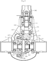
- FIG. 5 is a vertical sectional view of a general differential for an automobile.
- a drive pinion shaft 101 is received on an input side of a differential case 100, and is supported by a pair of tapered roller bearings 5 and 6 so as to be rotatable.
- a propeller shaft 102 is coupled to one end portion of the drive pinion shaft 101, and a drive pinion gear (deceleration small gear) 104 which meshes with a link gear (deceleration large gear) 103 is integrally provided to another end portion of the drive pinion shaft 101.
- the link gear 103 is coupled to a differential gear case 105, and the differential gear case 105 is supported by a pair of tapered roller bearings 7 and 8 so as to be rotatable relative to the differential case 100.
- a pair of pinion gears 106 and a pair of side gears 107, which mesh with the pair of pinion gears 106, are arranged inside the differential gear case 105.
- the pinion gears 106 are mounted to a pinion shaft 108, and the side gears 107 are mounted to the differential gear case 105.
- Right and left drive shafts (not shown) are coupled (for example, by serration coupling) to radially inner portions of the side gears 107.
- the tapered roller bearing for an automobile corresponds to each of the tapered roller bearings 5 to 8 described above.
- Drive torque of the propeller shaft 102 is transmitted through the drive pinion gear 104, the link gear 103, the differential gear case 105, the pinion gears 106, the side gears 107, and the drive shafts in the stated order.
- the raceway surfaces of the inner ring and the outer ring being the raceway rings each have a straight generating line shape, and carburized steel is used as a material of the inner ring and the outer ring.
- the logarithmic crowning is formed only in the rolling surfaces of the tapered rollers being the rolling elements, and high carbon chromium bearing steel is used as a material of the tapered rollers.
- Specific configurations and operations and effects of the tapered roller bearings 5 to 8 are similar to those of the tapered roller bearing 1. Thus, the description as to the tapered roller bearing 1 is similarly applied, and description thereof is omitted.
Landscapes
- Engineering & Computer Science (AREA)
- General Engineering & Computer Science (AREA)
- Mechanical Engineering (AREA)
- Manufacturing & Machinery (AREA)
- Rolling Contact Bearings (AREA)
Abstract
Description
- The present invention relates to a tapered roller bearing for an automobile, and more particularly, to a tapered roller bearing for an automobile which is to be suitably used for a transmission or a differential of an automobile.
- With regard to a tapered roller bearing for an automobile to be used for, for example, a transmission or a differential, in order to deal with application of a large load or misalignment, it is required that a contact stress which is generated on raceway surfaces (including rolling surfaces of rollers) of the tapered roller bearing be suppressed to an appropriate magnitude. In order to set a contact surface pressure (edge surface pressure) on the raceway surfaces of the tapered roller bearing to fall within an appropriate range, it is required that crowning be formed. Specifically, attempts have been made with various methods such as a method of forming crowning in each of an inner ring, an outer ring, and rollers and a method of forming large crowning or logarithmic crowning only in the rollers.
- Among those methods, as a method which is capable of attaining the most appropriate contact surface pressure and minimizing the stress generated inside the raceway surface to extend a bearing lifetime, there have been proposed, in
Patent Document 1, a logarithmic crowning function, which is obtained by modifying the Johns-Gohar's function through introduction of three design parameters thereto, and a roller bearing. - Moreover, according to
Patent Document 2, with regard to a crowning shape for attaining an appropriate surface pressure, a range of a crowning drop amount at each of two points of a roller in a generating line direction from a center of a rolling element or a raceway ring is defined irrespective of the crowning shape. Further, according toPatent Document 3, there has been proposed a method of forming logarithmic crowning in a roller and forming logarithmic crowning also in any one of an inner ring and an outer ring. -
- Patent Document 1:
JP 5037094 B2 - Patent Document 2:
JP 3731401 B2 - Patent Document 3:
JP 2010-106974 A - When crowning is to be formed, in consideration of ease of processing and cost, it is preferred that single-curve crowning or logarithmic crowning having a large drop amount be formed in the rolling surfaces of the tapered rollers being rolling elements. Further, in consideration of ease of processing and cost, it has been found out that it is also preferred that the raceway surfaces of the inner ring and the outer ring each have a single-curve crowning shape having a small drop amount or a straight shape having no crowning shape.
- In usage of the tapered roller bearing, there is a case in which the tapered roller bearing is used with strong interference fitting. Therefore, it is preferred that carburized steel be used as a material of the raceway ring. Moreover, carburized steel is used also for the rollers.
- However, in consideration of a case in which crowning is formed only in the rolling surfaces of the tapered rollers, it is required that a large drop amount be given. The increase in drop amount leads to increase in grinding amount. As a result, there arises a problem in that a heat-treated hardened layer for a top layer which is applied to attain a long lifetime becomes shallower. The present invention focuses on this problem.
- In view of the problem described above, the present invention has an object to provide a tapered roller bearing for an automobile, which is capable of achieving suppression of a contact surface pressure and increase in lifetime at low cost.
- As a result of various studies having been conducted to achieve the object described above, the inventor of the present invention has arrived at the present invention based on an idea in terms of processing, that is, forming logarithmic crowning only in the rolling surfaces of the tapered rollers and an idea in terms of a material, that is, preventing degradation of an effect of thermal treatment applied to achieve increase in lifetime.
- As a technical measure for achieving the above-mentioned object, according to one embodiment of the present invention, there is provided a tapered roller bearing for an automobile, comprising: an inner ring comprising a raceway surface having a tapered shape on an outer periphery; an outer ring comprising a raceway surface having a tapered shape on an inner periphery; a plurality of tapered rollers incorporated into a space defined between the raceway surfaces; and a retainer configured to receive the plurality of tapered rollers, wherein the inner ring and the outer ring are each made of carburized steel, wherein the raceway surfaces of the inner ring and the outer ring each have a straight generating line shape, wherein the tapered rollers each are made of high carbon chromium bearing steel, wherein the tapered rollers each have a rolling surface comprising: a straight portion, which is formed at a center portion in an axial direction; and crowning portions, which extend from the straight portion to both end portions, and wherein the crowning portions are each formed of logarithmic crowning.
- With the configuration described above, suppression of the contact surface pressure in the tapered roller bearing for an automobile and the increase in lifetime can be achieved at low cost.
- Herein, terms described in Description and Claims are defined as follows. The term "automobile" refers to "vehicle including a motor and a steering device and being capable of traveling on the ground with use of those components while a passenger rides on the vehicle" as defined in JIS D 0101-1993. As representatives of the automobile, there are given, for example, a passenger car, a bus, a truck, an all-terrain vehicle (ATV), a motorcycle, a construction vehicle, and an industrial vehicle. A tapered roller bearing for such automobile generally has an outer-ring outer diameter of from about ϕ50 mm to about ϕ150 mm. Moreover, the term "logarithmic crowning" refers to, in addition to crowning having a logarithmic curve, crowning which is approximated to a logarithmic curve including a plurality of arcs having different curvature radii which are smoothly connected. Further, the term "straight generating line shape" of the raceway surface refers to, in addition to a linear generating line shape, a substantially linear generating line shape with crowning having a drop amount of several micrometers.
- It is preferred that a ratio Dr/Dw of a drop amount Dr of the crowning portion of the rolling surface described above to a roller diameter Dw fall within a range of from 0.003 to 0.03. With this, the edge surface pressure can be set to an appropriate value.
- The tapered roller bearing for an automobile according to one embodiment of the present invention is to be suitably used for, in particular, a transmission or a differential.
- According to the present invention, suppression of the contact surface pressure in the tapered roller bearing for an automobile and increase in lifetime of the tapered roller bearing can be achieved at low cost.
-
-
FIG. 1 is a vertical sectional view for illustrating a part of a speed changer for an automobile for which a tapered roller bearing for an automobile according to one embodiment of the present invention is used. -
FIG. 2 is a vertical sectional view of the tapered roller bearing for an automobile according to one embodiment of the present invention. -
FIG. 3 is an enlarged front view of a tapered roller ofFIG. 2 . -
FIG. 4 is an enlarged view for illustrating the portion B ofFIG. 3 . -
FIG. 5 is a vertical sectional view for illustrating a differential for which the tapered roller bearing for an automobile according to one embodiment of the present invention is used. - With reference to
FIG. 1 to FIG. 5 , description is made of a tapered roller bearing for an automobile (hereinafter simply referred to also as "tapered roller bearing") according to one embodiment of the present invention. First, with reference toFIG. 1 , description is made of an outline of a speed changer for an automobile (transmission for an automobile) for which the tapered roller bearing according to this embodiment is used. -
FIG. 1 is a vertical sectional view for illustrating main parts of an example of a speed changer for an automobile to which the tapered roller bearing according to this embodiment is mounted. Thisspeed changer 30 is a synchromesh speed changer. Aninput shaft 32 is supported so as to be rotatable by amission case 31 through intermediation of a tapered roller bearing 2, and amain shaft 33 is arranged coaxially with theinput shaft 32. Theinput shaft 32 and themain shaft 33 are supported so as to be relatively rotatable by a tapered roller bearing 3 at a pilot portion. Although illustration is omitted, other parts of themain shaft 33 are also supported by tapered roller bearings. Anauxiliary shaft 34 which is arranged so as to be parallel to theinput shaft 32 and themain shaft 33 and apart therefrom by a predetermined distance is supported so as to be rotatable by themission case 31. Theauxiliary shaft 34 is supported by a tapered roller bearing 1 and another tapered roller bearing (not shown). Theinput shaft 32 has an input shaft gear (hereinafter simply referred to also as "gear") 35 formed integrally therewith, and always meshes with an auxiliary shaft gear (hereinafter simply referred to also as "gear") 36 of theauxiliary shaft 34. - Moreover, a main shaft gear (hereinafter simply referred to also as "gear") 43 is mounted to the
main shaft 33 so as to be rotatable through intermediation of a tapered roller bearing 4 at an idler portion. Themain shaft gear 43 always meshes with agear 37 of theauxiliary shaft 34. The tapered roller bearing for an automobile according to this embodiment corresponds to each of thetapered roller bearings 1 to 4 and other tapered roller bearings (not shown). Among the tapered roller bearings, the tapered roller bearing 3 at the pilot portion comprises an outer ring 3o being a component also serving as thegear 35, and the tapered roller bearing 4 at the idler portion comprises an outer ring 4o being a component also serving as thegear 43. The outer ring 3o and the outer ring 4o also correspond to the outer ring described in Description and Claims. - A
dog clutch 38 is coupled to a portion of theinput shaft 32 adjacent to thegear 35. Thedog clutch 38 integrally hasdog teeth 38a and acone 38b. Thedog teeth 38a are formed on an outer periphery of thedog clutch 38. Thecone 38b has a conical shape and is formed on one side of thedog clutch 38. Asynchronization mechanism 39 is arranged close to thedog clutch 38. Similarly to thegear 35 of theinput shaft 32, anotherdog clutch 38 is coupled to a portion of themain shaft 33 adjacent to thegear 43. Thedog clutch 38 integrally hasdog teeth 38a and acone 38b. Thedog teeth 38a are formed on an outer periphery of thedog clutch 38. Thecone 38b has a conical shape and is formed on one side of thedog clutch 38. Thesynchronization mechanism 39 is arranged close to thedog clutch 38. - The
synchronization mechanism 39 comprises asleeve 40, asynchronizer key 41, ahub 42, synchronizer rings 44, apressing pin 45, and aspring 46. Thesleeve 40 moves in an axial direction (right-and-left direction inFIG. 1 ) by actuation of a selector (not shown). Thesynchronizer key 41 is mounted to an inner periphery of thesleeve 40 so as to be movable in the axial direction. Thehub 42 is engaged with and coupled to an outer peripheral surface of themain shaft 33. The synchronizer rings 44 are slidably mounted to outer peripheral surfaces of thecones 38b of thedog clutches 38. Thepressing pin 45 and thespring 46 are configured to elastically press thesynchronizer key 41 toward an inner periphery of thesynchronizer key 41. - In the state illustrated in
FIG. 1 , thesleeve 40 and thesynchronizer key 41 are held at a neutral position by thepressing pin 45. When thesleeve 40 moves toward the right side in the axial direction from the state illustrated inFIG. 1 by actuation of the selector, thesynchronizer key 41 follows thesleeve 40 to move toward the right side in the axial direction and press thesynchronizer ring 44 against an inclination surface of thecone 38b of thedog clutch 38. With this, the rotation speed of thedog clutch 38 is reduced, whereas the rotation speed on thesynchronization mechanism 39 side is increased. When both rotation speeds are synchronized, thesleeve 40 further moves to the right side in the axial direction, and thesynchronizer key 41 is caused to mesh with thedog teeth 38a of thedog clutch 38. As a result, themain shaft gear 43 and themain shaft 33 are coupled to each other through intermediation of thesynchronization mechanism 39. With this, the rotation of the auxiliary shaft gear is transmitted to themain shaft gear 43, and hence themain shaft 33 rotates with a predetermined transmission gear ratio. Reversely, when thesleeve 40 moves toward the left side in the axial direction from the state illustrated inFIG. 1 , theinput shaft 32 and themain shaft 33 are coupled to each other through intermediation of thesynchronization mechanism 39, and hence themain shaft 33 rotates at a rotation speed as high as that of theinput shaft 32. In such a manner, a gear shift operation is performed. - Next, with reference to
FIG. 2 to FIG. 5 , detailed description is made of the tapered roller bearing according to this embodiment.FIG. 2 is a vertical sectional view for illustrating an upper half from a center line of the tapered roller bearing according to this embodiment. Description is made of the taperedroller bearing 1 configured to support theauxiliary shaft 34 inFIG. 1 as an example. The taperedroller bearings 2 to 4 are the same as the taperedroller bearing 1, and hence description thereof is omitted. - As illustrated in
FIG. 2 , the taperedroller bearing 1 comprises aninner ring 12, anouter ring 13, taperedrollers 14, and aretainer 15. The taperedrollers 14 are incorporated between theinner ring 12 and theouter ring 13. Theretainer 15 is configured to retain the taperedrollers 14. Theinner ring 12 has araceway surface 12a, a small-flange portion 12b, and a large-flange portion 12c. Theraceway surface 12a has a tapered shape and is formed on an outer periphery of theinner ring 12. The small-flange portion 12b is formed on a small-diameter side. The large-flange portion 12c is formed on a large-diameter side. Theouter ring 13 has araceway surface 13a. Theraceway surface 13a has a tapered shape and is formed on an inner periphery of theouter ring 13. The plurality of taperedrollers 14 are incorporated between theraceway surface 12a of theinner ring 12 and theraceway surface 13a of theouter ring 13. The taperedrollers 14 are received inpockets 15a of theretainer 15 and are retained at equal intervals in a circumferential direction. - A
ground relief portion 12f is formed at a corner portion at which theraceway surface 12a of theinner ring 12 and a large-flange surface 12e of the large-flange portion 12c intersect each other. A ground relief portion 12g is formed at a corner portion at which theraceway surface 12a and a small-flange surface 12d of the small-flange portion 12b intersect each other. A generating line of theraceway surface 12a extending in the axial direction is linearly formed. Moreover, a generating line of theraceway surface 13a of theouter ring 13 extending in the axial direction is also linearly formed. Theraceway surface 12a of theinner ring 12 has theground relief portions 12f and 12g. Thus, an effective raceway surface width Li of theraceway surface 12a is smaller than an effective rolling surface width Le (seeFIG. 3 ) of a rollingsurface 16 of the taperedroller 14. The contact surface pressure becomes more disadvantageous by such difference. - The rolling
surface 16 having a tapered shape is formed on an outer periphery of the taperedroller 14. Asmall end surface 14a is formed on the small-diameter side, and alarge end surface 14b is formed on the large-diameter side. Thelarge end surface 14b of the taperedroller 14 is received on the large-flange surface 12e of theinner ring 12. As illustrated inFIG. 3 , the rollingsurface 16 of the taperedroller 14 comprises astraight portion 16a and crowningportions straight portion 16a is formed at a center portion in the axial direction. The crowningportions FIG. 3 , the drop amount of each of the crowningportions portions FIG. 2 , theretainer 15 comprises a small-diameter sideannular portion 15b, a large-diameter sideannular portion 15c, and a plurality ofcolumnar portions 15d connecting the small-diameter sideannular portion 15b and the large-diameter sideannular portion 15c to each other in the axial direction. - The outline of the tapered roller bearing according to this embodiment is as described above. Next, with reference to
FIG. 2 to FIG. 4 , description is made of a characteristic configuration of the tapered roller bearing according to this embodiment.FIG. 3 is an enlarged front view of the tapered roller ofFIG. 2 .FIG. 4 is an enlarged view for illustrating the portion B ofFIG. 3 . The characteristic configuration of the tapered roller bearing according to this embodiment is achieved based on a combination of an idea in terms of processing, that is, forming the logarithmic crowning only in the rolling surfaces of the tapered rollers and an idea in terms of a material, that is, preventing degradation of an effect of thermal treatment applied to achieve increase in lifetime. The raceway surfaces of the inner ring and the outer ring being the raceway rings each have a straight generating line shape, and carburized steel is used as a material of the inner ring and the outer ring. Moreover, the logarithmic crowning is formed only in the rolling surfaces of the tapered rollers being the rolling elements, and high carbon chromium bearing steel is used as a material of the tapered rollers. - As illustrated in
FIG. 2 , theraceway surface 12a of theinner ring 12 and theraceway surface 13a of theouter ring 13 each have a straight generating line shape. In this embodiment, theraceway surface 12a and theraceway surface 13a each having the linear generating line shape are illustrated as an example. However, not limited to this, a substantially linear generating line shape with single-curve crowning having a small drop amount of about 5 µm (middle protruding shape) and a small curvature may be given. - The
inner ring 12 and theouter ring 13 are each made of carburized steel such as chromium steel (for example, SCR435) or chromium molybdenum steel (for example, SCM435). Although illustration is omitted, the top surfaces of theraceway surface 12a of theinner ring 12 and theraceway surface 13a of theouter ring 13 each have a quench-hardened layer formed by carburizing, quenching, and tempering, and has a surface hardness of from about HRC 58 to about HRC 63. An effective hardened-layer depth of the quench-hardened layer in each of the raceway surfaces 12a and 13a after grinding falls within a range of from 0.3 mm to 0.5 mm or larger. The raceway surfaces 12a and 13a each have a straight generating line shape. Therefore, the grinding amount is small, and hence the effective hardened-layer depth of a required amount can be secured even after grinding. With this, a bearing function is secured, and the raceway surfaces 12a and 13a are applicable to a usage involving strong interference fitting. The effective hardened-layer depth generally falls within a range of equal to or larger than Hv 513 (HRC 50). - In the tapered
roller bearing 3 at the pilot portion and the taperedroller bearing 4 at the idler portion illustrated inFIG. 1 , the outer rings 3o and 4o are components serving also as thegears - The chromium steel and the chromium molybdenum steel are given as examples of the carburized steel. However, not limited to those, there may be employed, for example, a 5120 material, a 4118 material, an 8620 material, a 4320 material, and a 9310 material conforming to ASTM A534 standard, as corresponding materials.
- As illustrated in
FIG. 3 , the rollingsurface 16 of the taperedroller 14 comprises thestraight portion 16a at a center portion in the axial direction and the crowningportions portions straight portion 16a of the rollingsurface 16 of the taperedroller 14 is set so as to fall within a range of from 50% to 85% of the effective rolling surface width Le. Therefore, skew can be suppressed, and the contact surface pressure can be reduced. Further, ease of processing is excellent, and hence manufacturing cost can be reduced. - In terms of a material, the tapered
roller 14 is made of high carbon chromium bearing steel (for example, SUJ2). The taperedroller 14 is entirely hardened from the top surface to the inside by entire quenching (through-hardening) and has a uniform hardness of from about HRC 58 to about HRC 63. Therefore, even when the grinding amount is large due to formation of the logarithmic crowning having a large drop amount, the quenching hardness of the rollingsurface 16 of the taperedroller 14 can be kept, and the bearing function can be maintained. With this, the tapered roller bearing for an automobile according to this embodiment can suppress the contact surface pressure and achieve long lifetime at low cost. - As high carbon chromium bearing steel other than SUJ2, there may be also employed SUJ3 or SUJ5. Alternatively, as a corresponding material, there may be employed, for example, a 52100 material conforming to the ASTM A295 standard or a
Grade 1 material or aGrade 2 material conforming to the ASTM A485 standard. - Now, description is made of the logarithmic crowning. The generating line of each of the crowning
portions 5037094 
- A: =2Q/πIE'
- a: Length from an original point O to an end of an effective contact portion
- E': Equivalent elastic modulus
- K1: Parameter representing a degree of a curvature of crowning
- K2: Parameter representing a ratio of crowning length with respect to "a"
- I: Length of an effective contact portion in a generating line direction
- Q: Load
- y: Position of the contact portion in the generating line direction
- z(y): Drop amount at an axial position "y"
- zm: Parameter representing an optimum value of a maximum drop amount of crowning at an end in an effective length of a roller
- The design parameters K1, K2, and zm in the logarithmic crowning expression described above are subjected to design. Description is made of a mathematical optimization method for the logarithmic crowning. Through determination of the design parameter K2 and appropriate selection of K1 and zm in the function expression expressing the logarithmic crowning, optimum logarithmic crowning can be designed. In general, the crowning is designed so as to reduce the surface pressure of the contact portion or a maximum value of stress. It is assumed that the rolling fatigue lifetime occurs in accordance with the von Mises yield criterion, and the parameters K1 and zm are selected so as to minimize a maximum value of the von Mises equivalent stress. The parameters K1 and zm can be selected with use of an appropriate mathematical optimization method. Various algorithms for mathematical optimization methods have been proposed, and the direct search method as one example is capable of executing optimization without use of derivatives of function, and is effective for a case in which an objective function and variables cannot be directly expressed with use of expressions. In this case, the parameters K1 and zm are determined with use of the Rosenbrock method as one of direct search methods.
- The shape of each of the crowning
portions roller 14 in this embodiment is the logarithmic curve crowning determined by the expression described above. However, the shape is not limited to that determined by the expression described above, but the logarithmic curve may be determined with use of another logarithmic crowning expression. - The crowning
portions roller 14 illustrated inFIG. 3 each have crowning having a shape approximated to the logarithmic curve of the logarithmic crowning determined by the expression described above. With reference toFIG. 4 , description is made of details of thecrowning portion 16b formed on thelarge end surface 14b side of the taperedroller 14. InFIG. 4 , for easy understanding of the drop amount of thecrowning portion 16b, more emphasis is given as compared to the taperedroller 14 illustrated inFIG. 3 . The crowningportion 16b has a complex arc shape formed by smoothly connecting three arcs having large curvature radii R1, R2, and R3 to thestraight portion 16a. As the drop amounts of thecrowning portion 16b, there are defined a drop amount Dr1 at a first gate, an intermediate drop amount Dr2 at a second gate, and a maximum drop amount Dr3 at a third gate so that the crowning shape approximated to the logarithmic curve is formed. The drop amount Dr3 corresponds to Dr in Description and Claims. Moreover, the drop amount Dr3 corresponds to zm inExpression 1 described above. With this, surface pressure distribution in the axial direction can be set uniform while avoiding the edge surface pressure. The drop amount depends on the size or the model number, but is about 60 µm at maximum. The crowningportion 16c formed in thesmall end surface 14a is similar to thecrowning portion 16b, and hence description thereof is omitted. The straight portion of the rolling surface of the tapered roller described in Description and Claims is referred to as a portion having a linear shape and a portion having a substantially linear shape with crowning having a drop amount of about several micrometers. - Regions of the crowning
portions ground relief portions 12f and 12g of theinner ring 12 ofFIG. 2 are not brought into contact with theinner ring 12. It is not always required that theraceway surface 16 of the taperedroller 14 in this region have the logarithmic crowning, and this region may be the linear shape, the arc shape, or other shape by which the crowningportions - A gap S, which is illustrated in
FIG. 2 , between thesmall end surface 14a of the taperedroller 14 and the small-flange surface 12d is set so as to be equal to or smaller than 0.3 mm. Therefore, the effect of suppressing skew can be attained. Further, the adapting rotation performed at the time of assembly of the taperedroller bearing 1 is reduced, thereby improving ease of assembly. - Next, description is made of the following issue. That is, as a specification for a large load, the tapered
roller 14 in the taperedroller bearing 1 according to this embodiment is made of high carbon chromium bearing steel, and with such configuration, even when the drop amount of the crowning is increased, there arises no problem in terms of a bearing function and in terms of processing. In the taperedroller 14 illustrated inFIG. 3 , a ratio Dr/Dw of the drop amount Dr of thecrowning portion surface 16 to a roller diameter Dw falls within a range of from 0.003 to 0.03. Verification results thereof are shown in Table 1.[Table 1] Roller diameter Dw [mm] φ10 φ10 φ15 φ20 φ10 φ10 Crowning drop amount Dr of roller [mm] 0.015 0.030 0.060 0.100 0.3 0.4 Crowning drop amount Dr of roller/roller diameter Dw 0.0015 0.003 0.004 0.005 0.03 0.04 Contact surface pressure × ○ ○ ○ ○ ○ Influence on lifetime ○ ○ ○ ○ ○ ○ Ease of processing ○ ○ ○ ○ ○ × Determination × ○ ○ ○ ○ × - As shown in Table 1, when the ratio Dr/Dw of the crowning drop amount Dr of the roller to the roller diameter Dw is smaller than 0.003, the contact surface pressure (edge surface pressure) becomes larger, with the result that there is difficulty in practical use. Meanwhile, it was verified that, when the ratio Dr/Dw is larger than 0.03, there is difficulty in manufacturing. Based on the verification results described above, when the ratio Dr/Dw is set within the range of from 0.003 to 0.03, the edge surface pressure can be set to an appropriate value. Moreover, ease of processing is excellent, and hence the manufacturing cost can be reduced.
- Meanwhile, description is made of verification results of a related-art tapered roller bearing given in the course of development. In the related-art tapered roller bearing, the inner ring and the outer ring being the raceway rings and the tapered rollers being rolling elements are subjected to carburizing, quenching, and tempering with carburized steel. Then, as a specification for a large load, cut crowning is formed in the raceway surfaces of the inner ring and the outer ring, and full crowning (single-curve crowning having a drop amount of about several micrometers) is formed in the rolling surfaces of the tapered rollers. In order to reduce the edge surface pressure, a large drop amount is required for the raceway surfaces of the inner ring and the outer ring due to application of the cut crowning. In order to reduce the edge surface pressure, the cut crowning requires a drop amount of from about 15 µm to about 30 µm for the inner ring. Moreover, in a case of application to the outer ring, the raceway surface width is longer than the rolling surface of the tapered roller. Thus, a larger drop amount is required, and hence is set to from about 50 µm to about 100 µm.
- When the crowning drop amount of the related art is given only to the tapered roller, a large drop amount is required. For example, when the roller diameter is ϕ20 mm, a drop amount of about 0.1 mm is required. However, when the grinding of 0.1 mm is performed, there is a fear in that the quench-hardened layer depth of the carburized steel causes the lifetime to be shortened. Therefore, a relationship between each roller diameter and a crowning drop amount of the roller was verified. The verification results are shown in Table 2.
[Table 2] Roller diameter Dw [mm] φ10 φ10 φ15 φ20 φ20 or larger Crowning drop amount Dr of roller [mm] 0.015 0.030 0.060 0.100 0.3 Crowning drop amount Dr of roller/roller diameter Dw 0.0015 0.003 0.004 0.005 0.03 Contact surface pressure × ○ ○ ○ ○ Influence on lifetime ○ ○ ○ × × Ease of processing ○ ○ ○ ○ × Determination × ○ ○ × × - As shown in Table 2, when the crowning drop amount Dr was set to 0.015 mm in the tapered roller having a roller diameter of ϕ10 mm, the edge surface pressure causing an adverse effect was generated, with the result that the determination result of "not applicable" was given. Moreover, in the tapered roller having a roller diameter of larger than ϕ20 mm, the crowning drop amount Dr became excessively larger. Thus, the hardened layer depth after grinding became smaller with the quench-hardened layer depth of the carburized steel, with the result that the determination result of "not applicable" was given.
- As a result of various studies conducted based on the verification results of the related-art tapered roller bearing described above, based on the idea in terms of processing, that is, forming the logarithmic crowning only in the rolling surfaces of the tapered rollers and the idea in terms of a material, that is, preventing degradation of an effect of thermal treatment applied to achieve increase in lifetime, the inventor of the present invention has arrived at the tapered roller bearing for an automobile according to this invention having the following configuration. That is, the raceway surfaces of the inner ring and the outer ring being the raceway rings each have a straight generating line shape, and carburized steel is used as a material of the inner ring and the outer ring. Moreover, the logarithmic crowning is formed only in the rolling surfaces of the tapered rollers being the rolling elements, and high carbon chromium bearing steel is used as a material of the tapered rollers.
- Next, with reference to
FIG. 5 , description is made of a differential for an automobile to which the tapered roller bearing for an automobile according to this embodiment is applied.FIG. 5 is a vertical sectional view of a general differential for an automobile. Adrive pinion shaft 101 is received on an input side of adifferential case 100, and is supported by a pair of taperedroller bearings propeller shaft 102 is coupled to one end portion of thedrive pinion shaft 101, and a drive pinion gear (deceleration small gear) 104 which meshes with a link gear (deceleration large gear) 103 is integrally provided to another end portion of thedrive pinion shaft 101. - The
link gear 103 is coupled to adifferential gear case 105, and thedifferential gear case 105 is supported by a pair of taperedroller bearings differential case 100. A pair of pinion gears 106 and a pair of side gears 107, which mesh with the pair of pinion gears 106, are arranged inside thedifferential gear case 105. The pinion gears 106 are mounted to apinion shaft 108, and the side gears 107 are mounted to thedifferential gear case 105. Right and left drive shafts (not shown) are coupled (for example, by serration coupling) to radially inner portions of the side gears 107. The tapered roller bearing for an automobile according to this embodiment corresponds to each of the taperedroller bearings 5 to 8 described above. - Drive torque of the
propeller shaft 102 is transmitted through thedrive pinion gear 104, thelink gear 103, thedifferential gear case 105, the pinion gears 106, the side gears 107, and the drive shafts in the stated order. - Similarly to the tapered
roller bearing 1 described above, also in each of the taperedroller bearings 5 to 8, the raceway surfaces of the inner ring and the outer ring being the raceway rings each have a straight generating line shape, and carburized steel is used as a material of the inner ring and the outer ring. Moreover, the logarithmic crowning is formed only in the rolling surfaces of the tapered rollers being the rolling elements, and high carbon chromium bearing steel is used as a material of the tapered rollers. Specific configurations and operations and effects of the taperedroller bearings 5 to 8 are similar to those of the taperedroller bearing 1. Thus, the description as to the taperedroller bearing 1 is similarly applied, and description thereof is omitted. - The present invention is not limited to the above-mentioned embodiment. As a matter of course, the present invention may be carried out in various modes without departing from the spirit of the present invention. The scope of the present invention is defined in claims, and encompasses equivalents described in claims and all changes within the scope of claims.
-
- 1
- tapered roller bearing
- 2
- tapered roller bearing for automobile
- 3
- tapered roller bearing for automobile
- 4
- tapered roller bearing for automobile
- 5
- tapered roller bearing for automobile
- 6
- tapered roller bearing for automobile
- 7
- tapered roller bearing for automobile
- 8
- tapered roller bearing for automobile
- 12
- inner ring
- 12a
- raceway surface
- 12b
- small-flange portion
- 12c
- large-flange portion
- 12d
- small-flange surface
- 12e
- large-flange surface
- 12f
- ground relief portion
- 12g
- ground relief portion
- 13
- outer ring
- 13a
- raceway surface
- 14
- tapered roller
- 14a
- small end surface
- 14b
- large end surface
- 15
- retainer
- 16
- rolling surface
- 16a
- straight portion
- 16b
- crowning portion
- 16c
- crowning portion
- Dr
- drop amount at end portion of crowning
- Dw
- roller diameter
- L
- roller length
- Le
- effective rolling surface width
- Li
- effective raceway surface width
- Ls
- width of straight portion
- S
- gap
Claims (3)
- A tapered roller bearing for an automobile, comprising:an inner ring comprising a raceway surface having a tapered shape on an outer periphery;an outer ring comprising a raceway surface having a tapered shape on an inner periphery;a plurality of tapered rollers incorporated into a space defined between the raceway surfaces; anda retainer configured to receive the plurality of tapered rollers,wherein the inner ring and the outer ring are each made of carburized steel,wherein the raceway surfaces of the inner ring and the outer ring each have a straight generating line shape,wherein the tapered rollers each are made of high carbon chromium bearing steel,wherein the tapered rollers each have a rolling surface comprising:a straight portion, which is formed at a center portion in an axial direction; andcrowning portions, which extend from the straight portion to both end portions, andwherein the crowning portions are each formed of logarithmic crowning.
- The tapered roller bearing for an automobile according to claim 1, wherein a ratio Dr/Dw of a drop amount (Dr) of the crowning portion of the rolling surface to a roller diameter (Dw) falls within a range of from 0.003 to 0.03.
- The tapered roller bearing for an automobile according to claim 1 or 2, wherein the tapered roller bearing for an automobile is to be used for a transmission or a differential.
Applications Claiming Priority (2)
| Application Number | Priority Date | Filing Date | Title |
|---|---|---|---|
| JP2016146151A JP6740050B2 (en) | 2016-07-26 | 2016-07-26 | Tapered roller bearings for automobiles |
| PCT/JP2017/023981 WO2018020951A1 (en) | 2016-07-26 | 2017-06-29 | Tapered roller bearing for automobile |
Publications (3)
| Publication Number | Publication Date |
|---|---|
| EP3492759A1 true EP3492759A1 (en) | 2019-06-05 |
| EP3492759A4 EP3492759A4 (en) | 2020-06-24 |
| EP3492759B1 EP3492759B1 (en) | 2022-06-08 |
Family
ID=61017398
Family Applications (1)
| Application Number | Title | Priority Date | Filing Date |
|---|---|---|---|
| EP17833960.2A Active EP3492759B1 (en) | 2016-07-26 | 2017-06-29 | Tapered roller bearing for automobile |
Country Status (5)
| Country | Link |
|---|---|
| US (1) | US11268571B2 (en) |
| EP (1) | EP3492759B1 (en) |
| JP (1) | JP6740050B2 (en) |
| CN (1) | CN109416075B (en) |
| WO (1) | WO2018020951A1 (en) |
Families Citing this family (4)
| Publication number | Priority date | Publication date | Assignee | Title |
|---|---|---|---|---|
| JP6739968B2 (en) * | 2016-04-01 | 2020-08-12 | Ntn株式会社 | Tapered roller bearing |
| WO2021153793A1 (en) * | 2020-01-30 | 2021-08-05 | 日本精工株式会社 | Roller bearing |
| DE102020130456A1 (en) * | 2020-11-18 | 2022-05-19 | Aktiebolaget Skf | tapered roller bearing |
| JP2024021306A (en) * | 2022-08-03 | 2024-02-16 | Ntn株式会社 | roller bearing |
Family Cites Families (23)
| Publication number | Priority date | Publication date | Assignee | Title |
|---|---|---|---|---|
| JPS5037094B1 (en) | 1971-02-17 | 1975-11-29 | ||
| JP3731401B2 (en) | 1999-08-31 | 2006-01-05 | 日本精工株式会社 | Roller bearing |
| JP4158845B2 (en) | 1999-10-13 | 2008-10-01 | 株式会社ジェイテクト | Tapered roller bearings |
| US7488113B2 (en) | 2003-04-16 | 2009-02-10 | Nsk Ltd. | Roller bearing for belt-type stepless speed changer |
| JP2005076675A (en) * | 2003-08-28 | 2005-03-24 | Ntn Corp | Tapered roller bearing for transmission of automobile |
| JP4364610B2 (en) * | 2003-11-25 | 2009-11-18 | Ntn株式会社 | Roller bearing |
| JP4592444B2 (en) | 2005-02-25 | 2010-12-01 | Ntn株式会社 | Tapered roller bearing |
| JP2007051714A (en) | 2005-08-18 | 2007-03-01 | Jtekt Corp | Tapered roller bearing and vehicle pinion shaft support device using the same |
| JP2007170418A (en) * | 2005-12-19 | 2007-07-05 | Ntn Corp | Tapered roller bearing |
| JP5037094B2 (en) | 2006-11-15 | 2012-09-26 | Ntn株式会社 | Roller bearing |
| JP5251431B2 (en) | 2008-10-30 | 2013-07-31 | 日本精工株式会社 | Tapered roller bearing |
| JP2010248568A (en) * | 2009-04-15 | 2010-11-04 | Nsk Ltd | Rolling bearing for hydrogen atmosphere |
| JP5334665B2 (en) * | 2009-04-24 | 2013-11-06 | Ntn株式会社 | Tapered roller bearing and design method thereof |
| JP2011208751A (en) | 2010-03-30 | 2011-10-20 | Ntn Corp | Rolling bearing, method for manufacturing roller, and roller machining device |
| JP2012107693A (en) | 2010-11-17 | 2012-06-07 | Jtekt Corp | Rolling bearing device for cam-follower |
| CN202108870U (en) * | 2011-06-09 | 2012-01-11 | 上虞市英耐特轴承有限公司 | Taper roller automobile hub bearing |
| JP2014052069A (en) * | 2012-08-06 | 2014-03-20 | Nsk Ltd | Cylindrical roller bearing |
| CN203257879U (en) * | 2013-05-28 | 2013-10-30 | 哈尔滨新哈精密轴承股份有限公司 | Inner-ring rib-free unangular-outer-ring double-rib oil groove and oil hole free precise bearing |
| DE102014219702A1 (en) * | 2014-09-29 | 2016-03-31 | Aktiebolaget Skf | Raceway structure for a rolling bearing and method |
| CN104565022A (en) * | 2014-12-31 | 2015-04-29 | 浙江大学 | Variable-contact angle tapered roller bearing |
| JP6798780B2 (en) * | 2015-01-28 | 2020-12-09 | Ntn株式会社 | Tapered roller bearing |
| JP2017094404A (en) * | 2015-11-18 | 2017-06-01 | Ntn株式会社 | Superfinish processing method of bearing roller and superfinish processor |
| CN105583588B (en) * | 2016-03-24 | 2017-12-12 | 哈尔滨汽车轴承有限公司 | A kind of processing method for taper roll bearing Internal and external cycle |
-
2016
- 2016-07-26 JP JP2016146151A patent/JP6740050B2/en active Active
-
2017
- 2017-06-29 US US16/319,605 patent/US11268571B2/en active Active
- 2017-06-29 CN CN201780042851.4A patent/CN109416075B/en active Active
- 2017-06-29 WO PCT/JP2017/023981 patent/WO2018020951A1/en not_active Ceased
- 2017-06-29 EP EP17833960.2A patent/EP3492759B1/en active Active
Also Published As
| Publication number | Publication date |
|---|---|
| JP2018017263A (en) | 2018-02-01 |
| US20210301867A1 (en) | 2021-09-30 |
| US11268571B2 (en) | 2022-03-08 |
| EP3492759B1 (en) | 2022-06-08 |
| CN109416075B (en) | 2021-09-14 |
| EP3492759A4 (en) | 2020-06-24 |
| JP6740050B2 (en) | 2020-08-12 |
| CN109416075A (en) | 2019-03-01 |
| WO2018020951A1 (en) | 2018-02-01 |
Similar Documents
| Publication | Publication Date | Title |
|---|---|---|
| EP3492759B1 (en) | Tapered roller bearing for automobile | |
| CN110325748B (en) | Tapered roller bearing | |
| EP3511586B1 (en) | Tapered roller bearing | |
| EP3438487A1 (en) | Tripod constant-velocity universal joint and method for heat-treating tripod member | |
| WO2014021428A1 (en) | Retainer for constant-velocity universal joint, fixed constant-velocity universal joint incorporating same, and drive shaft incorporating said fixed constant-velocity universal joint | |
| EP3438480B1 (en) | Tapered roller bearing | |
| JP4731945B2 (en) | Constant velocity universal joint, cage for constant velocity universal joint, and manufacturing method thereof | |
| US7488270B2 (en) | Toroidal continuously variable transmission and method for producing torque transmitting member thereof | |
| EP3842648B1 (en) | Tapered roller bearing | |
| WO2023032631A1 (en) | Tripod-type constant velocity universal joint | |
| JP6594719B2 (en) | Tripod type constant velocity universal joint | |
| US8661679B2 (en) | Bearing device for vehicle and method of manufacturing the same | |
| EP3940252A1 (en) | Rolling bearing | |
| JP2024016668A (en) | ball bearing | |
| WO2024101264A1 (en) | Rolling bearing | |
| JP2007253192A (en) | Manufacturing method of shaft | |
| JP2008309294A (en) | Synchronizer ring |
Legal Events
| Date | Code | Title | Description |
|---|---|---|---|
| STAA | Information on the status of an ep patent application or granted ep patent |
Free format text: STATUS: THE INTERNATIONAL PUBLICATION HAS BEEN MADE |
|
| PUAI | Public reference made under article 153(3) epc to a published international application that has entered the european phase |
Free format text: ORIGINAL CODE: 0009012 |
|
| STAA | Information on the status of an ep patent application or granted ep patent |
Free format text: STATUS: REQUEST FOR EXAMINATION WAS MADE |
|
| 17P | Request for examination filed |
Effective date: 20190213 |
|
| AK | Designated contracting states |
Kind code of ref document: A1 Designated state(s): AL AT BE BG CH CY CZ DE DK EE ES FI FR GB GR HR HU IE IS IT LI LT LU LV MC MK MT NL NO PL PT RO RS SE SI SK SM TR |
|
| AX | Request for extension of the european patent |
Extension state: BA ME |
|
| DAV | Request for validation of the european patent (deleted) | ||
| DAX | Request for extension of the european patent (deleted) | ||
| A4 | Supplementary search report drawn up and despatched |
Effective date: 20200525 |
|
| RIC1 | Information provided on ipc code assigned before grant |
Ipc: F16C 33/62 20060101ALI20200516BHEP Ipc: F16C 19/36 20060101ALI20200516BHEP Ipc: F16C 33/58 20060101ALI20200516BHEP Ipc: F16C 19/38 20060101AFI20200516BHEP Ipc: F16C 33/36 20060101ALI20200516BHEP Ipc: F16C 33/64 20060101ALI20200516BHEP |
|
| GRAP | Despatch of communication of intention to grant a patent |
Free format text: ORIGINAL CODE: EPIDOSNIGR1 |
|
| STAA | Information on the status of an ep patent application or granted ep patent |
Free format text: STATUS: GRANT OF PATENT IS INTENDED |
|
| INTG | Intention to grant announced |
Effective date: 20210827 |
|
| GRAJ | Information related to disapproval of communication of intention to grant by the applicant or resumption of examination proceedings by the epo deleted |
Free format text: ORIGINAL CODE: EPIDOSDIGR1 |
|
| STAA | Information on the status of an ep patent application or granted ep patent |
Free format text: STATUS: REQUEST FOR EXAMINATION WAS MADE |
|
| INTC | Intention to grant announced (deleted) | ||
| GRAP | Despatch of communication of intention to grant a patent |
Free format text: ORIGINAL CODE: EPIDOSNIGR1 |
|
| STAA | Information on the status of an ep patent application or granted ep patent |
Free format text: STATUS: GRANT OF PATENT IS INTENDED |
|
| INTG | Intention to grant announced |
Effective date: 20220121 |
|
| GRAS | Grant fee paid |
Free format text: ORIGINAL CODE: EPIDOSNIGR3 |
|
| GRAA | (expected) grant |
Free format text: ORIGINAL CODE: 0009210 |
|
| STAA | Information on the status of an ep patent application or granted ep patent |
Free format text: STATUS: THE PATENT HAS BEEN GRANTED |
|
| AK | Designated contracting states |
Kind code of ref document: B1 Designated state(s): AL AT BE BG CH CY CZ DE DK EE ES FI FR GB GR HR HU IE IS IT LI LT LU LV MC MK MT NL NO PL PT RO RS SE SI SK SM TR |
|
| REG | Reference to a national code |
Ref country code: AT Ref legal event code: REF Ref document number: 1497123 Country of ref document: AT Kind code of ref document: T Effective date: 20220615 Ref country code: CH Ref legal event code: EP |
|
| REG | Reference to a national code |
Ref country code: DE Ref legal event code: R096 Ref document number: 602017058373 Country of ref document: DE |
|
| REG | Reference to a national code |
Ref country code: IE Ref legal event code: FG4D |
|
| REG | Reference to a national code |
Ref country code: LT Ref legal event code: MG9D |
|
| REG | Reference to a national code |
Ref country code: NL Ref legal event code: MP Effective date: 20220608 |
|
| PG25 | Lapsed in a contracting state [announced via postgrant information from national office to epo] |
Ref country code: SE Free format text: LAPSE BECAUSE OF FAILURE TO SUBMIT A TRANSLATION OF THE DESCRIPTION OR TO PAY THE FEE WITHIN THE PRESCRIBED TIME-LIMIT Effective date: 20220608 Ref country code: NO Free format text: LAPSE BECAUSE OF FAILURE TO SUBMIT A TRANSLATION OF THE DESCRIPTION OR TO PAY THE FEE WITHIN THE PRESCRIBED TIME-LIMIT Effective date: 20220908 Ref country code: LT Free format text: LAPSE BECAUSE OF FAILURE TO SUBMIT A TRANSLATION OF THE DESCRIPTION OR TO PAY THE FEE WITHIN THE PRESCRIBED TIME-LIMIT Effective date: 20220608 Ref country code: HR Free format text: LAPSE BECAUSE OF FAILURE TO SUBMIT A TRANSLATION OF THE DESCRIPTION OR TO PAY THE FEE WITHIN THE PRESCRIBED TIME-LIMIT Effective date: 20220608 Ref country code: GR Free format text: LAPSE BECAUSE OF FAILURE TO SUBMIT A TRANSLATION OF THE DESCRIPTION OR TO PAY THE FEE WITHIN THE PRESCRIBED TIME-LIMIT Effective date: 20220909 Ref country code: FI Free format text: LAPSE BECAUSE OF FAILURE TO SUBMIT A TRANSLATION OF THE DESCRIPTION OR TO PAY THE FEE WITHIN THE PRESCRIBED TIME-LIMIT Effective date: 20220608 Ref country code: ES Free format text: LAPSE BECAUSE OF FAILURE TO SUBMIT A TRANSLATION OF THE DESCRIPTION OR TO PAY THE FEE WITHIN THE PRESCRIBED TIME-LIMIT Effective date: 20220608 Ref country code: BG Free format text: LAPSE BECAUSE OF FAILURE TO SUBMIT A TRANSLATION OF THE DESCRIPTION OR TO PAY THE FEE WITHIN THE PRESCRIBED TIME-LIMIT Effective date: 20220908 |
|
| REG | Reference to a national code |
Ref country code: AT Ref legal event code: MK05 Ref document number: 1497123 Country of ref document: AT Kind code of ref document: T Effective date: 20220608 |
|
| PG25 | Lapsed in a contracting state [announced via postgrant information from national office to epo] |
Ref country code: RS Free format text: LAPSE BECAUSE OF FAILURE TO SUBMIT A TRANSLATION OF THE DESCRIPTION OR TO PAY THE FEE WITHIN THE PRESCRIBED TIME-LIMIT Effective date: 20220608 Ref country code: LV Free format text: LAPSE BECAUSE OF FAILURE TO SUBMIT A TRANSLATION OF THE DESCRIPTION OR TO PAY THE FEE WITHIN THE PRESCRIBED TIME-LIMIT Effective date: 20220608 |
|
| PG25 | Lapsed in a contracting state [announced via postgrant information from national office to epo] |
Ref country code: NL Free format text: LAPSE BECAUSE OF FAILURE TO SUBMIT A TRANSLATION OF THE DESCRIPTION OR TO PAY THE FEE WITHIN THE PRESCRIBED TIME-LIMIT Effective date: 20220608 |
|
| PG25 | Lapsed in a contracting state [announced via postgrant information from national office to epo] |
Ref country code: SM Free format text: LAPSE BECAUSE OF FAILURE TO SUBMIT A TRANSLATION OF THE DESCRIPTION OR TO PAY THE FEE WITHIN THE PRESCRIBED TIME-LIMIT Effective date: 20220608 Ref country code: SK Free format text: LAPSE BECAUSE OF FAILURE TO SUBMIT A TRANSLATION OF THE DESCRIPTION OR TO PAY THE FEE WITHIN THE PRESCRIBED TIME-LIMIT Effective date: 20220608 Ref country code: RO Free format text: LAPSE BECAUSE OF FAILURE TO SUBMIT A TRANSLATION OF THE DESCRIPTION OR TO PAY THE FEE WITHIN THE PRESCRIBED TIME-LIMIT Effective date: 20220608 Ref country code: PT Free format text: LAPSE BECAUSE OF FAILURE TO SUBMIT A TRANSLATION OF THE DESCRIPTION OR TO PAY THE FEE WITHIN THE PRESCRIBED TIME-LIMIT Effective date: 20221010 Ref country code: EE Free format text: LAPSE BECAUSE OF FAILURE TO SUBMIT A TRANSLATION OF THE DESCRIPTION OR TO PAY THE FEE WITHIN THE PRESCRIBED TIME-LIMIT Effective date: 20220608 Ref country code: CZ Free format text: LAPSE BECAUSE OF FAILURE TO SUBMIT A TRANSLATION OF THE DESCRIPTION OR TO PAY THE FEE WITHIN THE PRESCRIBED TIME-LIMIT Effective date: 20220608 Ref country code: AT Free format text: LAPSE BECAUSE OF FAILURE TO SUBMIT A TRANSLATION OF THE DESCRIPTION OR TO PAY THE FEE WITHIN THE PRESCRIBED TIME-LIMIT Effective date: 20220608 |
|
| REG | Reference to a national code |
Ref country code: CH Ref legal event code: PL |
|
| REG | Reference to a national code |
Ref country code: BE Ref legal event code: MM Effective date: 20220630 |
|
| PG25 | Lapsed in a contracting state [announced via postgrant information from national office to epo] |
Ref country code: PL Free format text: LAPSE BECAUSE OF FAILURE TO SUBMIT A TRANSLATION OF THE DESCRIPTION OR TO PAY THE FEE WITHIN THE PRESCRIBED TIME-LIMIT Effective date: 20220608 Ref country code: IS Free format text: LAPSE BECAUSE OF FAILURE TO SUBMIT A TRANSLATION OF THE DESCRIPTION OR TO PAY THE FEE WITHIN THE PRESCRIBED TIME-LIMIT Effective date: 20221008 |
|
| REG | Reference to a national code |
Ref country code: DE Ref legal event code: R097 Ref document number: 602017058373 Country of ref document: DE |
|
| PG25 | Lapsed in a contracting state [announced via postgrant information from national office to epo] |
Ref country code: MC Free format text: LAPSE BECAUSE OF FAILURE TO SUBMIT A TRANSLATION OF THE DESCRIPTION OR TO PAY THE FEE WITHIN THE PRESCRIBED TIME-LIMIT Effective date: 20220608 Ref country code: AL Free format text: LAPSE BECAUSE OF FAILURE TO SUBMIT A TRANSLATION OF THE DESCRIPTION OR TO PAY THE FEE WITHIN THE PRESCRIBED TIME-LIMIT Effective date: 20220608 |
|
| PLBE | No opposition filed within time limit |
Free format text: ORIGINAL CODE: 0009261 |
|
| STAA | Information on the status of an ep patent application or granted ep patent |
Free format text: STATUS: NO OPPOSITION FILED WITHIN TIME LIMIT |
|
| PG25 | Lapsed in a contracting state [announced via postgrant information from national office to epo] |
Ref country code: LU Free format text: LAPSE BECAUSE OF NON-PAYMENT OF DUE FEES Effective date: 20220629 Ref country code: LI Free format text: LAPSE BECAUSE OF NON-PAYMENT OF DUE FEES Effective date: 20220630 Ref country code: IE Free format text: LAPSE BECAUSE OF NON-PAYMENT OF DUE FEES Effective date: 20220629 Ref country code: DK Free format text: LAPSE BECAUSE OF FAILURE TO SUBMIT A TRANSLATION OF THE DESCRIPTION OR TO PAY THE FEE WITHIN THE PRESCRIBED TIME-LIMIT Effective date: 20220608 Ref country code: CH Free format text: LAPSE BECAUSE OF NON-PAYMENT OF DUE FEES Effective date: 20220630 |
|
| 26N | No opposition filed |
Effective date: 20230310 |
|
| GBPC | Gb: european patent ceased through non-payment of renewal fee |
Effective date: 20220908 |
|
| PG25 | Lapsed in a contracting state [announced via postgrant information from national office to epo] |
Ref country code: SI Free format text: LAPSE BECAUSE OF FAILURE TO SUBMIT A TRANSLATION OF THE DESCRIPTION OR TO PAY THE FEE WITHIN THE PRESCRIBED TIME-LIMIT Effective date: 20220608 Ref country code: BE Free format text: LAPSE BECAUSE OF NON-PAYMENT OF DUE FEES Effective date: 20220630 |
|
| PG25 | Lapsed in a contracting state [announced via postgrant information from national office to epo] |
Ref country code: GB Free format text: LAPSE BECAUSE OF NON-PAYMENT OF DUE FEES Effective date: 20220908 |
|
| PG25 | Lapsed in a contracting state [announced via postgrant information from national office to epo] |
Ref country code: IT Free format text: LAPSE BECAUSE OF FAILURE TO SUBMIT A TRANSLATION OF THE DESCRIPTION OR TO PAY THE FEE WITHIN THE PRESCRIBED TIME-LIMIT Effective date: 20220608 |
|
| PG25 | Lapsed in a contracting state [announced via postgrant information from national office to epo] |
Ref country code: HU Free format text: LAPSE BECAUSE OF FAILURE TO SUBMIT A TRANSLATION OF THE DESCRIPTION OR TO PAY THE FEE WITHIN THE PRESCRIBED TIME-LIMIT; INVALID AB INITIO Effective date: 20170629 |
|
| PG25 | Lapsed in a contracting state [announced via postgrant information from national office to epo] |
Ref country code: MK Free format text: LAPSE BECAUSE OF FAILURE TO SUBMIT A TRANSLATION OF THE DESCRIPTION OR TO PAY THE FEE WITHIN THE PRESCRIBED TIME-LIMIT Effective date: 20220608 Ref country code: CY Free format text: LAPSE BECAUSE OF FAILURE TO SUBMIT A TRANSLATION OF THE DESCRIPTION OR TO PAY THE FEE WITHIN THE PRESCRIBED TIME-LIMIT Effective date: 20220608 |
|
| PG25 | Lapsed in a contracting state [announced via postgrant information from national office to epo] |
Ref country code: MT Free format text: LAPSE BECAUSE OF FAILURE TO SUBMIT A TRANSLATION OF THE DESCRIPTION OR TO PAY THE FEE WITHIN THE PRESCRIBED TIME-LIMIT Effective date: 20220608 |
|
| PG25 | Lapsed in a contracting state [announced via postgrant information from national office to epo] |
Ref country code: BG Free format text: LAPSE BECAUSE OF FAILURE TO SUBMIT A TRANSLATION OF THE DESCRIPTION OR TO PAY THE FEE WITHIN THE PRESCRIBED TIME-LIMIT Effective date: 20220608 |
|
| PG25 | Lapsed in a contracting state [announced via postgrant information from national office to epo] |
Ref country code: BG Free format text: LAPSE BECAUSE OF FAILURE TO SUBMIT A TRANSLATION OF THE DESCRIPTION OR TO PAY THE FEE WITHIN THE PRESCRIBED TIME-LIMIT Effective date: 20220608 |
|
| PGFP | Annual fee paid to national office [announced via postgrant information from national office to epo] |
Ref country code: DE Payment date: 20250507 Year of fee payment: 9 |
|
| PGFP | Annual fee paid to national office [announced via postgrant information from national office to epo] |
Ref country code: FR Payment date: 20250508 Year of fee payment: 9 |
|
| PG25 | Lapsed in a contracting state [announced via postgrant information from national office to epo] |
Ref country code: TR Free format text: LAPSE BECAUSE OF FAILURE TO SUBMIT A TRANSLATION OF THE DESCRIPTION OR TO PAY THE FEE WITHIN THE PRESCRIBED TIME-LIMIT Effective date: 20220608 |