EP3492754A1 - Construction machinery - Google Patents
Construction machinery Download PDFInfo
- Publication number
- EP3492754A1 EP3492754A1 EP18777939.2A EP18777939A EP3492754A1 EP 3492754 A1 EP3492754 A1 EP 3492754A1 EP 18777939 A EP18777939 A EP 18777939A EP 3492754 A1 EP3492754 A1 EP 3492754A1
- Authority
- EP
- European Patent Office
- Prior art keywords
- rotational speed
- center bypass
- flow control
- control valve
- directional flow
- Prior art date
- Legal status (The legal status is an assumption and is not a legal conclusion. Google has not performed a legal analysis and makes no representation as to the accuracy of the status listed.)
- Granted
Links
Images




Classifications
-
- E—FIXED CONSTRUCTIONS
- E02—HYDRAULIC ENGINEERING; FOUNDATIONS; SOIL SHIFTING
- E02F—DREDGING; SOIL-SHIFTING
- E02F9/00—Component parts of dredgers or soil-shifting machines, not restricted to one of the kinds covered by groups E02F3/00 - E02F7/00
- E02F9/20—Drives; Control devices
- E02F9/22—Hydraulic or pneumatic drives
- E02F9/2203—Arrangements for controlling the attitude of actuators, e.g. speed, floating function
-
- E—FIXED CONSTRUCTIONS
- E02—HYDRAULIC ENGINEERING; FOUNDATIONS; SOIL SHIFTING
- E02F—DREDGING; SOIL-SHIFTING
- E02F9/00—Component parts of dredgers or soil-shifting machines, not restricted to one of the kinds covered by groups E02F3/00 - E02F7/00
- E02F9/20—Drives; Control devices
- E02F9/22—Hydraulic or pneumatic drives
- E02F9/2221—Control of flow rate; Load sensing arrangements
-
- E—FIXED CONSTRUCTIONS
- E02—HYDRAULIC ENGINEERING; FOUNDATIONS; SOIL SHIFTING
- E02F—DREDGING; SOIL-SHIFTING
- E02F9/00—Component parts of dredgers or soil-shifting machines, not restricted to one of the kinds covered by groups E02F3/00 - E02F7/00
- E02F9/20—Drives; Control devices
- E02F9/22—Hydraulic or pneumatic drives
-
- E—FIXED CONSTRUCTIONS
- E02—HYDRAULIC ENGINEERING; FOUNDATIONS; SOIL SHIFTING
- E02F—DREDGING; SOIL-SHIFTING
- E02F9/00—Component parts of dredgers or soil-shifting machines, not restricted to one of the kinds covered by groups E02F3/00 - E02F7/00
- E02F9/20—Drives; Control devices
- E02F9/22—Hydraulic or pneumatic drives
- E02F9/2221—Control of flow rate; Load sensing arrangements
- E02F9/2225—Control of flow rate; Load sensing arrangements using pressure-compensating valves
- E02F9/2228—Control of flow rate; Load sensing arrangements using pressure-compensating valves including an electronic controller
-
- E—FIXED CONSTRUCTIONS
- E02—HYDRAULIC ENGINEERING; FOUNDATIONS; SOIL SHIFTING
- E02F—DREDGING; SOIL-SHIFTING
- E02F9/00—Component parts of dredgers or soil-shifting machines, not restricted to one of the kinds covered by groups E02F3/00 - E02F7/00
- E02F9/20—Drives; Control devices
- E02F9/22—Hydraulic or pneumatic drives
- E02F9/2221—Control of flow rate; Load sensing arrangements
- E02F9/2232—Control of flow rate; Load sensing arrangements using one or more variable displacement pumps
- E02F9/2235—Control of flow rate; Load sensing arrangements using one or more variable displacement pumps including an electronic controller
-
- E—FIXED CONSTRUCTIONS
- E02—HYDRAULIC ENGINEERING; FOUNDATIONS; SOIL SHIFTING
- E02F—DREDGING; SOIL-SHIFTING
- E02F9/00—Component parts of dredgers or soil-shifting machines, not restricted to one of the kinds covered by groups E02F3/00 - E02F7/00
- E02F9/20—Drives; Control devices
- E02F9/22—Hydraulic or pneumatic drives
- E02F9/2264—Arrangements or adaptations of elements for hydraulic drives
- E02F9/2267—Valves or distributors
-
- E—FIXED CONSTRUCTIONS
- E02—HYDRAULIC ENGINEERING; FOUNDATIONS; SOIL SHIFTING
- E02F—DREDGING; SOIL-SHIFTING
- E02F9/00—Component parts of dredgers or soil-shifting machines, not restricted to one of the kinds covered by groups E02F3/00 - E02F7/00
- E02F9/20—Drives; Control devices
- E02F9/22—Hydraulic or pneumatic drives
- E02F9/2278—Hydraulic circuits
- E02F9/2282—Systems using center bypass type changeover valves
-
- E—FIXED CONSTRUCTIONS
- E02—HYDRAULIC ENGINEERING; FOUNDATIONS; SOIL SHIFTING
- E02F—DREDGING; SOIL-SHIFTING
- E02F9/00—Component parts of dredgers or soil-shifting machines, not restricted to one of the kinds covered by groups E02F3/00 - E02F7/00
- E02F9/26—Indicating devices
- E02F9/264—Sensors and their calibration for indicating the position of the work tool
- E02F9/265—Sensors and their calibration for indicating the position of the work tool with follow-up actions (e.g. control signals sent to actuate the work tool)
-
- F—MECHANICAL ENGINEERING; LIGHTING; HEATING; WEAPONS; BLASTING
- F15—FLUID-PRESSURE ACTUATORS; HYDRAULICS OR PNEUMATICS IN GENERAL
- F15B—SYSTEMS ACTING BY MEANS OF FLUIDS IN GENERAL; FLUID-PRESSURE ACTUATORS, e.g. SERVOMOTORS; DETAILS OF FLUID-PRESSURE SYSTEMS, NOT OTHERWISE PROVIDED FOR
- F15B11/00—Servomotor systems without provision for follow-up action ; Circuits therefor
- F15B11/02—Systems essentially incorporating special features for controlling the speed or the actuating force of an output member
-
- F—MECHANICAL ENGINEERING; LIGHTING; HEATING; WEAPONS; BLASTING
- F15—FLUID-PRESSURE ACTUATORS; HYDRAULICS OR PNEUMATICS IN GENERAL
- F15B—SYSTEMS ACTING BY MEANS OF FLUIDS IN GENERAL; FLUID-PRESSURE ACTUATORS, e.g. SERVOMOTORS; DETAILS OF FLUID-PRESSURE SYSTEMS, NOT OTHERWISE PROVIDED FOR
- F15B11/00—Servomotor systems without provision for follow-up action ; Circuits therefor
- F15B11/08—Servomotor systems without provision for follow-up action ; Circuits therefor with only one servomotor
-
- E—FIXED CONSTRUCTIONS
- E02—HYDRAULIC ENGINEERING; FOUNDATIONS; SOIL SHIFTING
- E02F—DREDGING; SOIL-SHIFTING
- E02F3/00—Dredgers; Soil-shifting machines
- E02F3/04—Dredgers; Soil-shifting machines mechanically-driven
- E02F3/46—Dredgers; Soil-shifting machines mechanically-driven with reciprocating digging or scraping elements moved by cables or hoisting ropes ; Drives or control devices therefor
- E02F3/50—Dredgers; Soil-shifting machines mechanically-driven with reciprocating digging or scraping elements moved by cables or hoisting ropes ; Drives or control devices therefor with buckets or other digging elements moved along a rigid guideway
Definitions
- the present invention relates to a construction machine such as a hydraulic excavator, and in particular relates to a construction machine such as a hydraulic excavator that performs slow speed operation works such as crane works.
- Patent Document 1 discloses a hydraulic drive control system of construction machines that is capable of reducing work machine operation speeds.
- Patent Document 1 describes a hydraulic drive control system having: a prime mover; a hydraulic pump driven by this prime mover; an actuator driven by hydraulic fluid that occurs from this hydraulic pump; operation means provided to this actuator; a directional control valve that is switchingly operated according to an operation direction and operation amount of an operation lever of this operation means and controls a flow of the hydraulic fluid supplied to the actuator; a pilot pump that produces a pilot primary pressure; and a pilot valve that is provided to the operation means, produces a pilot secondary pressure according to the operation direction and operation amount of the operation lever based on the pilot primary pressure and causes the directional control valve to function.
- This hydraulic drive control system can reduce work machine working speeds by reducing rotational speeds of prime movers and reducing delivery rates of hydraulic pumps.
- Patent Document 1 Japanese Patent No. 4215409
- the present invention is made in view of the above-mentioned problems, and an object thereof is to provide a construction machine. If the rotational speed of a prime mover is set lower than a rated rotational speed and the delivery rate of a hydraulic pump is lowered, the construction machine can prevent deterioration of the operability in slow speed operation works by keeping wide a lever operation range in which the rate of flow supplied to a hydraulic actuator is variable.
- the present invention provides a construction machine including a hydraulic control system.
- the hydraulic control system includes: a prime mover; a variable displacement hydraulic pump driven by the prime mover; a plurality of hydraulic actuators driven by discharge fluid of the hydraulic pump; a plurality of center bypass directional flow control valves arranged in a center bypass line having an upstream end connected to the hydraulic pump and a downstream end connected to a hydraulic fluid tank, and controlling flows of hydraulic fluid supplied from the hydraulic pump to the plurality of hydraulic actuators; and a plurality of operation devices provided correspondingly to the plurality of hydraulic actuators and operating the respective directional flow control valves.
- the construction machine is characterized by including: an operation amount sensor detecting operation amounts of the plurality of directional flow control valves; a rotational speed sensor detecting a rotational speed of the prime mover; a center bypass control valve arranged downstream of the plurality of directional flow control valves in the center bypass line; and a controller that is configured to calculate, if the rotational speed of the prime mover detected by the rotational speed sensor is lower than a rated rotational speed which is an engine rotational speed used at a time of a normal work, a combined opening area obtained by combining opening areas of the plurality of directional flow control valves in the center bypass line based on the operation amounts of the plurality of operation devices detected by the operation amount sensor, and to control the center bypass control valve such that an opening area of the center bypass control valve becomes smaller than the combined opening area.
- the rotational speed of the prime mover is set lower than the rated rotational speed, and the delivery rate of the hydraulic pump is lowered, an increase of the lever operation amount with which the hydraulic fluid starts flowing into a load holding side of the hydraulic actuator, i.e., with which the hydraulic actuator starts moving, can be suppressed.
- a lever operation range in which the rate of flow supplied to the hydraulic actuator is variable is kept wide, deterioration of operability in slow speed operation works can be prevented.
- a lever operation range in which the rate of flow supplied to a hydraulic actuator is variable can be kept wide, and deterioration of the operability in slow speed operation works can be prevented.
- FIG. 1 is a figure illustrating an external appearance of a hydraulic excavator as one example of construction machines according to the present embodiment.
- a hydraulic excavator includes a lower track structure 100, an upper swing structure 101, and a front work implement 102.
- the lower track structure 100 has left and right, crawler-type track devices 103a and 103b, and is driven by left and right travelling motors 104a and 104b.
- the upper swing structure 101 is mounted on the lower track structure 100 such that the upper swing structure 101 can swing, and is swing-driven by a swing motor not illustrated.
- the front work implement 102 is attached to a front portion of the upper swing structure 101 such that the front work implement 102 can revolve in the upward and downward directions.
- the upper swing structure 101 is provided with an engine room 106 and a cabin (cab) 107.
- an engine (prime mover) 6 and hydraulic equipment such as a hydraulic pump 4 or a pilot pump 9 are arranged in the engine room 106.
- operation devices such as operation lever units 13, 24, and 27 illustrated in FIG. 2 or an operation pedal device not illustrated are arranged in the cabin 107.
- the front work implement 102 has an articulated structure having a boom 111, an arm 112 and a bucket 113.
- the boom 111 revolves in the upward and downward directions along with expansion and contraction of a boom cylinder 8.
- the arm 112 revolves in the upward and downward directions and forward and backward directions along with expansion and contraction of an arm cylinder 60.
- the bucket 113 revolves in the upward and downward directions and forward and backward directions along with expansion and contraction of a bucket cylinder 80.
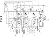
- FIG. 2 is an overall configuration diagram of a hydraulic control system mounted on the hydraulic excavator illustrated in FIG. 1 .
- FIG. 2 for the sake of simplicity of explanation, portions related to the left and right travelling motors 104a and 104b, and hydraulic actuators such as the arm cylinder 60 or the bucket cylinder 80 illustrated in FIG. 1 are omitted.
- the hydraulic control system in the present embodiment includes: the variable displacement hydraulic pump (main pump) 4 and the fixed displacement pilot pump 9 that are driven by the engine 6; the plurality of hydraulic actuators 8, 60, and 80 driven by hydraulic fluid discharged from the hydraulic pump 4; and a control valve device 11 having built-in pilot-type directional flow control valves 1, 20, and 21 that control flowing directions and flow rates of hydraulic fluid supplied from the hydraulic pump 4 to the hydraulic actuators 8, 60, and 80.
- a discharged fluid line of the hydraulic pump 4 is connected to a hydraulic fluid tank T via a main relief valve 22.
- the main relief valve 22 opens, and discharges hydraulic fluid to the hydraulic fluid tank T.
- a discharged fluid line of the pilot pump 9 is connected to the hydraulic fluid tank T via a pilot relief valve 23.
- the pilot relief valve 23 opens, and discharges hydraulic fluid to the hydraulic fluid tank T.
- the directional flow control valves 1, 20, and 21 are of center bypass-type, and are arranged on a center bypass line 12 communicating with the discharged fluid line of the hydraulic pump 4. That is, the center bypass line 12 extends penetrating through the directional flow control valves 1, 20, and 21. An upstream end of the center bypass line 12 is connected to the discharged fluid line of the hydraulic pump 4, and a downstream end thereof is connected to the hydraulic fluid tank T.
- the hydraulic actuator 8 is a hydraulic cylinder (boom cylinder) that raises and lowers the boom 111, and the directional flow control valve 1 is a first directional flow control valve for boom control.
- the hydraulic actuator 60 is a hydraulic cylinder (arm cylinder) that pushes and pulls the arm 112, and the directional flow control valve 20 is a second directional flow control valve for arm control.
- the hydraulic actuator 80 is a hydraulic cylinder (bucket cylinder) that pushes and pulls the bucket 113, and the directional flow control valve 21 is a third directional flow control valve for bucket control.
- the boom cylinder 8 is connected to the directional flow control valve 1 via actuator lines 16 and 17.
- the boom cylinder 8 has a bottom-side cylinder chamber 8a and a rod-side cylinder chamber 8b.
- the bottom-side cylinder chamber 8a is connected to the actuator line 16, and the rod-side cylinder chamber 8b is connected to the actuator line 17.
- the boom cylinder 8 is supplied with discharge fluid of the hydraulic pump 4 via the directional flow control valve 1. Since the same applies to the arm cylinder 60 and the bucket cylinder 80, explanations thereof are omitted.
- the operation lever unit 13 is a first operation lever unit for boom operation.
- the operation lever unit 13 has a pressure reducing valve that generates, based on the discharge pressure of the pilot pump 9, an operation pilot pressure Pp1 (hereinafter, referred to as a "boom-raising operation pilot pressure”) as a boom-raising command or an operation pilot pressure Pp2 (hereinafter, referred to as a “boom-lowering operation pilot pressure”) as a boom-lowering command that correspond to an operation direction of an operation lever 13a.
- the generated operation pilot pressure Pp1 or Pp2 is guided to a corresponding pressure-receiving section of the directional flow control valve 1, and the directional flow control valve 1 is switched to a boom-raising direction (the leftward direction in the illustration) or a boom-lowering direction (the rightward direction in the illustration) by the operation pilot pressure Pp1 or Pp2.
- the operation lever unit 24 is a second operation lever unit for arm operation.
- the operation lever unit 24 has a pressure reducing valve that generates, based on the discharge pressure of the pilot pump 9, an operation pilot pressure Pp3 (hereinafter, referred to as a "arm-pulling operation pilot pressure") as an arm-crowding (arm-pulling) command or an operation pilot pressure Pp4 (hereinafter, referred to as a “arm-pushing operation pilot pressure”) as an arm-dumping (arm-pushing) command that correspond to an operation direction of an operation lever 24a.
- an operation pilot pressure Pp3 hereinafter, referred to as a "arm-pulling operation pilot pressure”
- an operation pilot pressure Pp4 hereinafter, referred to as a "arm-pushing operation pilot pressure”
- the generated operation pilot pressure Pp3 or Pp4 is guided to a corresponding pressure-receiving section of the directional flow control valve 20, and the directional flow control valve 20 is switched to an arm-crowding direction (the leftward direction in the illustration) or an arm-dumping direction (the rightward direction in the illustration) by the operation pilot pressure Pp3 or Pp4.
- the operation lever unit 27 is a third operation lever unit for bucket operation.
- the operation lever unit 27 has a pressure reducing valve that generates, based on the discharge pressure of the pilot pump 9, an operation pilot pressure Pp5 (hereinafter, referred to as a “bucket-pulling operation pilot pressure”) as a bucket-crowding (bucket-pulling) command or an operation pilot pressure Pp6 (hereinafter, referred to as a “bucket-pushing operation pilot pressure”) as a bucket-dumping (bucket-pushing) command that correspond to an operation direction of an operation lever 27a.
- an operation pilot pressure Pp5 hereinafter, referred to as a "bucket-pulling operation pilot pressure”
- Pp6 hereinafter, referred to as a “bucket-pushing operation pilot pressure”
- Bucket-pushing operation pilot pressure bucket-dumping (bucket-pushing) command that correspond to an operation direction of an operation lever 27a.
- the generated operation pilot pressure Pp5 or Pp6 is guided to a corresponding pressure-receiving section of the directional flow control valve 21, and the directional flow control valve 21 is switched to a bucket-crowding direction (the leftward direction in the illustration) or a bucket-dumping direction (the rightward direction in the illustration) by the operation pilot pressure Pp5 or Pp6.
- FIG. 3A is a diagram illustrating enlarged graphic symbols of the directional flow control valves 1, 20, and 21.
- the center bypass directional flow control valves 1, 20, and 21 each have a center bypass passage portion Rb, a meter-in passage portion Ri and a meter-out passage portion Ro.
- the center bypass passage portion Rb is positioned on the center bypass line 12
- the meter-in passage portion Ri is positioned on a hydraulic line that establishes communication between a hydraulic fluid supply line 18 and the actuator line 16 or 17, the hydraulic fluid supply line 18 communicating with the discharged fluid line of the hydraulic pump 4.
- the meter-out passage portion Ro is positioned on a hydraulic line that establishes communication between the actuator line 16 or 17 and the hydraulic fluid tank T.
- the hydraulic fluid supply line 18 is provided with a load check valve 15 for preventing a reverse flow of hydraulic fluid from the hydraulic actuator side.
- the directional flow control valves 1, 20, and 21 adjust opening areas of the three passage portions Rb, Ri, and Ro according to their switching amounts (strokes) to thereby divide the delivery rate of the hydraulic pump 4 and supply hydraulic fluid to the hydraulic actuators 8, 60, and 80.
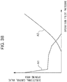
- FIG. 3B is a figure illustrating opening area characteristics of the directional flow control valves 1, 20, and 21.
- the center bypass passage portion Rb has opening area characteristics like the ones illustrated as A1, and the meter-in passage portion Ri and the meter-out passage portion Ro have opening area characteristics like the ones illustrated as A2.
- the horizontal axis in FIG. 3B indicates operation pilot pressures generated by a corresponding operation device, and approximately correspond to an operation amount of an operation lever (hereinafter, referred to as a "lever operation amount") or a spool stroke of the directional flow control valves 1, 20, and 21.
- the vertical axis in FIG. 3B indicates the opening area of the center bypass passage portion Rb, the meter-in passage portion Ri or the meter-out passage portion Ro.
- an opening area A1 of the center bypass passage portion Rb decreases, and opening areas A2 of the meter-in passage portion Ri and the meter-out passage portion Ro increase.
- the opening area A2 of the meter-in passage portion Ri increases, and the opening area A1 of the center bypass passage portion Rb decreases; therefore, the discharge pressure of the hydraulic pump 4 becomes higher than the load pressure of the hydraulic actuator, part of discharge fluid of the hydraulic pump 4 flows into the hydraulic actuator via the meter-in passage portion Ri, and the hydraulic actuator starts operating.
- the stroke of the directional flow control valve increases further, correspondingly the opening area A2 of the meter-in passage portion Ri increases, and the opening area A1 of the center bypass passage portion Rb decreases; therefore, the flow rate of hydraulic fluid supplied to the hydraulic actuator via the meter-in passage portion Ri increases, and a speed of the hydraulic actuator also increases.
- the opening area characteristics illustrated in FIG. 3B are optimized for each of the directional flow control valves 1, 20, and 21 according to a capacity of a hydraulic actuator or operability of an operation lever.
- the hydraulic pump 4 includes a regulator 5.
- the regulator 5 receives inputs of a pump control pressure Ppc and the discharge pressure of the hydraulic pump 4 that it relates to, and performs positive control and input torque limiting control.
- the hydraulic control system in the present embodiment further has, as its characteristic configurations: a center bypass control valve 2 arranged downstream of the directional flow control valves 1, 20, and 21 in the center bypass line 12; a pressure sensor (first pressure sensor) 7 that detects the boom-raising operation pilot pressure Pp1; a pressure sensor (second pressure sensor) 25 that detects the arm-pulling operation pilot pressure Pp3; a pressure sensor (third pressure sensor) 26 that detects the arm-pushing operation pilot pressure Pp4; a pressure sensor (fourth pressure sensor) 28 that detects the bucket-pulling operation pilot pressure Pp5; a pressure sensor (fifth pressure sensor) 29 that detects the bucket-pushing operation pilot pressure Pp6; a rotational speed sensor (rotational speed sensor) 19 that detects a rotational speed of the engine 6; a controller (controller) 10; and a solenoid proportional valve 3 that functions according to control signals from the controller 10 and generates a control pressure Pcb based on the discharge pressure of the pilot pump 9.
- FIG. 4 is a flowchart illustrating processing content of the controller 10.
- the controller 10 decides at Step S1 whether or not any of the boom-raising operation pilot pressure Pp1, the arm-pulling operation pilot pressure Pp3, the arm-pushing operation pilot pressure Pp4, the bucket-pulling operation pilot pressure Pp5 and the bucket-pushing operation pilot pressure Pp6 is higher than a predetermined value Ppmin.
- the predetermined value Ppmin is a minimum value of operation pilot pressures generated by the operation devices 13, 24, and 27, and an operation pilot pressure being higher than the predetermined value Ppmin means that an operation lever has been operated.
- the operation pilot pressures Pp1 to Pp6 correspond to operation amounts of the directional flow control valves 1, 20, and 21, and the pressure sensors 7, 25, 26, 28, and 29 constitute an operation amount sensor that detects operation amounts of the directional flow control valves 1, 20, and 21.
- Step S1 If it is decided at Step S1 that any of the operation pilot pressures Pp1 to Pp5 is higher than the predetermined value Ppmin (YES), the controller 10 further decides at Step S2, based on a detection signal of the rotational speed sensor 19, whether or not a rotational speed N of the engine 6 is lower than a predetermined value Nmax.
- Step S2 If it is decided at Step S2 that the rotational speed N of the engine 6 is lower than the predetermined value Nmax (NO), an opening area Acb of the center bypass control valve 2 is calculated at Step S3. A method of calculating the opening area Acb is described below.
- Step S1 if it is decided at Step S1 that the boom-raising operation pilot pressure Pp1 is not higher than the predetermined value Ppmin (NO) or if it is decided at Step S2 that the engine rotational speed N is not lower than the predetermined value Nmax (NO), the opening area Acb of the center bypass control valve 2 is set to a maximum value (fully opened) at Step S4.
- Step S5 the solenoid proportional valve 3 such that the opening area Acb of the center bypass control valve 2 matches the opening area set at Step S3 or S4.
- the controller 10 calculates a control pressure Pcb corresponding to the opening area set at Step S3 or S4 in FIG. 4 , and excites the solenoid proportional valve 3 such that the control pressure Pcb is generated by the solenoid proportional valve 3.
- the opening area Acb of the center bypass control valve 2 is controlled.
- FIG. 6 is a block diagram illustrating a center bypass opening area calculation process at Step S3 in FIG. 4 .
- Step S3 is constituted by calculation blocks B1 to B8, and the opening area Acb of the center bypass control valve 2 is calculated based on the operation pilot pressures Pp1 and Pp3 to Pp6 and the engine rotational speed N.
- the opening area of the center bypass passage portion Rb of the directional flow control valve 1 corresponding to the boom-raising operation pilot pressure Pp1 is calculated based on a conversion table T1.
- the opening area characteristics A1, illustrated in FIG. 3A , of the center bypass passage portion Rb of the directional flow control valve 20 are set in the conversion table T1.
- the opening area of the center bypass passage portion Rb of the directional flow control valve 20 corresponding to the arm-pulling operation pilot pressure Pp2 is calculated based on a conversion table T2.
- the opening area characteristics of the center bypass passage portion Rb of the directional flow control valve 20 are set in the conversion table T2.
- the opening area of the center bypass passage portion Rb of the directional flow control valve 20 corresponding to the arm-pushing operation pilot pressure Pp3 is calculated based on a conversion table T3.
- the opening area characteristics of the center bypass passage portion Rb of the directional flow control valve 20 are set in the conversion table T3.
- the opening area of the center bypass passage portion Rb of the directional flow control valve 21 corresponding to the bucket-pulling operation pilot pressure Pp4 is calculated based on a conversion table T4.
- the opening area characteristics of the center bypass passage portion Rb of the directional flow control valve 21 are set in the conversion table T4.
- the opening area of the center bypass passage portion Rb of the directional flow control valve 21 corresponding to the bucket-pushing operation pilot pressure Pp5 is output based on a conversion table T5.
- the opening area characteristics of the center bypass passage portion Rb of the directional flow control valve 21 are set in the conversion table T5.
- a minimum value among the opening areas calculated at the calculation blocks B1 to B5, or among the opening areas of the center bypass passage portions Rb of the directional flow control valves 1, 20, and 21, is selected. This selection of the minimum value is equivalent to obtaining a combined opening area that is obtained by combining the opening areas of the directional flow control valves 1, 20, and 21 at the center bypass passage portions Rb.
- the center bypass passage portions Rb (center bypass restrictors) of the directional flow control valves 1, 20, and 21 are connected in series on the center bypass line 12, and a restrictor with the smallest opening area has dominant effects in a configuration with restrictors connected in series.
- calculation of the combined opening area of the center bypass passage portions Rb of the directional flow control valves 1, 20, and 21 is simplified by approximately calculating the minimum value among the opening areas of the center bypass passage portions Rb as the combined opening area.
- the slow speed operation work is assumingly a crane work, and load in the boom-lowering direction does not occur; therefore, at the calculation block B6, the boom-lowering operation pressure Pp2 is not taken into consideration.
- the minimum value needs to be selected from a group including also the boom-lowering operation pressure Pp2.
- the rated rotational speed Nmax is an engine rotational speed used at the time of a normal work.
- the opening area Acb of the center bypass control valve 2 is calculated by multiplying the combined opening area calculated at the calculation block B6 by the correction coefficient (0 to 1) calculated at the calculation block B7.
- This calculation is equivalent to obtaining the opening area Acb of the center bypass control valve 2 when the combined opening area of the center bypass passage portions Rb of the directional flow control valves 1, 20, and 21 and the center bypass control valve 2 becomes a value obtained by multiplying the combined opening area of the center bypass passage portions Rb of the directional flow control valves 1, 20, and 21 by the above-mentioned correction coefficient (0 to 1).
- the restrictor of the center bypass control valve 2 becomes dominant in the center bypass line 12, and the combined opening area of the center bypass passage portions Rb of the directional flow control valves 1, 20, and 21 and the center bypass control valve 2 approximately matches the opening area of the center bypass control valve 2.
- the combined opening area of the center bypass passage portions Rb of the directional flow control valves 1, 20, and 21 and the center bypass control valve 2 can be made approximately match a value obtained by multiplying the combined opening area of the center bypass passage portions Rb of the directional flow control valves 1, 20, and 21 by the correction coefficient (0 to 1).
- FIG. 7 is a figure illustrating a relation between the operation pilot pressures Pp1 and Pp3 to Pp6 of the directional flow control valves 1, 20, and 21 and the opening area Acb of the center bypass control valve 2 (control characteristics of the center bypass control valve 2) .
- C0 indicates control characteristics in a case where the engine rotational speed N is set to the rated rotational speed Nmax, and irrespective of the operation pilot pressures, the opening area Acb of the center bypass control valve 2 becomes the maximum value (fully opened).
- C1 indicates control characteristics in a case where the engine rotational speed N is set to N1 lower than the rated rotational speed N0
- C2 indicates control characteristics in a case where the engine rotational speed N is set to N2 lower than N1, and they both approximately match ones obtained by multiplying the combined opening area, indicated by a broken line in the figure, of the directional flow control valves 1, 20, and 21 by ratios (correction coefficients) of the engine rotational speeds N1 and N2 to the rated rotational speed Nmax.
- a rear portion of the bucket 113 is equipped with a hook 130 that can be housed.
- the hook 130 is for crane works, and, as illustrated, a suspended load 131 is hung by a wire hooked on the hook 130 attached to the bucket rear portion.
- the suspended load 131 is moved (positionally adjusted) in the upward and downward directions (in a height direction) by raising and lowering of the boom 111 (boom-raising and boom-lowering), and the suspended load 131 is moved (positionally adjusted) in the forward and backward directions and lateral directions (horizontal directions) by pushing and pulling of the arm 112 (arm-dumping and arm-crowding) or swinging.
- the suspended load 131 is moved upward by boom-raising in a state where the suspended load 131 is held in midair as illustrated in FIG. 1 .
- the operation pilot pressure Pp1 which is a boom-raising command is guided to the pressure-receiving section of the directional flow control valve 1 for boom, and the directional flow control valve 1 is operated to switch to the boom-raising direction (the leftward direction in the illustration).
- the operation pilot pressure Pp1 which is a boom-raising command is detected by the pressure sensor 7, and a detection signal of the pressure sensor 7 is input to the controller 10 together with a detection signal of the rotational speed sensor 19 that detects the rotational speed of the engine 6.
- the controller 10 performs the processes in the flowchart illustrated in FIG. 4 based on these detection signals.
- the operation pilot pressure Pp1 > Ppmin and the engine rotational speed N ⁇ Nmax results of the decisions at Steps S1 and S2 are both YES, and as a result of the processes at Steps S3 and S5, a control signal is output to the solenoid proportional valve 3.
- the opening area of the center bypass control valve 2 is controlled such that the combined opening area of the center bypass line 12 shrinks correspondingly to lowering of the engine rotational speed N.
- the discharge pressure of the hydraulic pump 4 rises correspondingly to an increase of the lever operation amount, and if the discharge pressure of the hydraulic pump 4 exceeds a high holding pressure for the bottom-side cylinder chamber 8a of the boom cylinder 8, the discharge fluid of the hydraulic pump 4 flows into the bottom-side cylinder chamber 8a of the boom cylinder 8 which is the load holding side, the boom cylinder 8 is extended, and the boom 111 revolves upward.
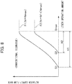
- FIG. 8 is a figure illustrating relations between lever operation amounts and actuator supply flow rates in a conventional technique.
- F1 indicates a relation in the case where the engine rotational speed N is set to the rated rotational speed Nmax
- F2 indicates a relation in the case where the engine rotational speed N is set lower than the rated rotational speed Nmax.
- a lever operation range up to the lever operation amount S1 becomes a dead zone
- a lever operation range between the lever operation amount S1 and a lever operation amount Smax where the rate of flow supplied to the hydraulic actuator becomes the maximum becomes a lever operation range X1 in which the rate of flow supplied to the hydraulic actuator is variable.
- the engine rotational speed N is set to N1 lower than the rated rotational speed Nmax, the delivery rate of the hydraulic pump 4 lowers proportionally to the engine rotational speed N, and the discharge pressure of the hydraulic pump 4 also lowers similarly.
- the lever operation amount reaches S1 in this state, the operation pilot pressure reaches PS1 in FIG. 7 , and the combined opening area of the center bypass passage portions Rb of the directional flow control valves 1, 20, and 21 shrinks to A11, but due to the lowered delivery rate of the hydraulic pump 4, the discharge pressure of the hydraulic pump 4 does not exceed the load pressure of the hydraulic actuator, and the hydraulic fluid does not flow into the load holding side of the hydraulic actuator.
- the operation lever is operated further, and the lever operation amount reaches S2, the operation pilot pressure reaches PS2 in FIG. 7 , and the combined opening area of the center bypass passage portions Rb of the directional flow control valves 1, 20, and 21 shrinks to A12 as illustrated in FIG. 7 .
- the discharge pressure of the hydraulic pump 4 exceeds the load pressure of the hydraulic actuator, and the hydraulic fluid starts flowing into the load holding side of the hydraulic actuator.
- the lever operation range up to the lever operation amount S2 becomes a dead zone, and the lever operation range in which the rate of flow supplied to the hydraulic actuator is variable shrinks from X1 to X2, and the operability in slow speed operation works deteriorates.
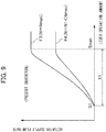
- FIG. 9 is a figure illustrating relations between lever operation amounts and actuator supply flow rates in the present embodiment.
- F3 indicates a relation in the case where the engine rotational speed N is set to the rated rotational speed Nmax
- F4 indicates a relation in the case where the engine rotational speed N is set lower than the rated rotational speed Nmax.
- the delivery rate of the hydraulic pump 4 lowers proportionally to the engine rotational speed N, and the discharge pressure of the hydraulic pump 4 also lowers similarly.
- the opening area Acb of the center bypass control valve 2 is controlled to be smaller than the combined opening area of the center bypass passage portions Rb of the directional flow control valves 1, 20, and 21 proportionally to lowering of the engine rotational speed N.
- the lever operation amount S1 with which the hydraulic fluid starts flowing into the load holding side of the hydraulic actuator, or with which the hydraulic actuator starts moving in the case where the engine rotational speed N is set to the rated rotational speed Nmax, the hydraulic fluid starts flowing into the load holding side of the hydraulic actuator.
- the present invention is not limited to the above-mentioned embodiment, but include various modifications.
- the present invention is applied to a hydraulic excavator, the present invention is not limited thereto, but can be applied to construction machines such as cranes.
- the above-mentioned embodiment is explained in detail in order to explain the present invention in an easy-to-understand manner, and is not necessarily limited to one including all the configurations explained.
Landscapes
- Engineering & Computer Science (AREA)
- General Engineering & Computer Science (AREA)
- Mining & Mineral Resources (AREA)
- Civil Engineering (AREA)
- Structural Engineering (AREA)
- Physics & Mathematics (AREA)
- Fluid Mechanics (AREA)
- Mechanical Engineering (AREA)
- Operation Control Of Excavators (AREA)
- Fluid-Pressure Circuits (AREA)
Abstract
Description
- The present invention relates to a construction machine such as a hydraulic excavator, and in particular relates to a construction machine such as a hydraulic excavator that performs slow speed operation works such as crane works.
- Construction machines such as hydraulic excavators are in some cases used at reduced work machine operation speeds in works that require careful operation such as crane works or ground leveling works (slow speed operation works).
Patent Document 1, for example, discloses a hydraulic drive control system of construction machines that is capable of reducing work machine operation speeds. -
Patent Document 1 describes a hydraulic drive control system having: a prime mover; a hydraulic pump driven by this prime mover; an actuator driven by hydraulic fluid that occurs from this hydraulic pump; operation means provided to this actuator; a directional control valve that is switchingly operated according to an operation direction and operation amount of an operation lever of this operation means and controls a flow of the hydraulic fluid supplied to the actuator; a pilot pump that produces a pilot primary pressure; and a pilot valve that is provided to the operation means, produces a pilot secondary pressure according to the operation direction and operation amount of the operation lever based on the pilot primary pressure and causes the directional control valve to function. This hydraulic drive control system can reduce work machine working speeds by reducing rotational speeds of prime movers and reducing delivery rates of hydraulic pumps. - Patent Document 1: Japanese Patent No.
4215409 - However, with the hydraulic drive control system described in
Patent Document 1, if the delivery rate of a hydraulic pump is lowered by setting the engine rotational speed lower than an engine rotational speed used at the time of a normal work (rated rotational speed), the lever operation amount increases when hydraulic fluid starts flowing into a load holding side of a hydraulic actuator, i.e., when the hydraulic actuator starts moving, and a lever operation range in which the rate of flow supplied to the hydraulic actuator is variable shrinks; therefore, operability in slow speed operation works deteriorates. - The present invention is made in view of the above-mentioned problems, and an object thereof is to provide a construction machine. If the rotational speed of a prime mover is set lower than a rated rotational speed and the delivery rate of a hydraulic pump is lowered, the construction machine can prevent deterioration of the operability in slow speed operation works by keeping wide a lever operation range in which the rate of flow supplied to a hydraulic actuator is variable.
- In order to achieve the above-mentioned object, the present invention provides a construction machine including a hydraulic control system. The hydraulic control system includes: a prime mover; a variable displacement hydraulic pump driven by the prime mover; a plurality of hydraulic actuators driven by discharge fluid of the hydraulic pump; a plurality of center bypass directional flow control valves arranged in a center bypass line having an upstream end connected to the hydraulic pump and a downstream end connected to a hydraulic fluid tank, and controlling flows of hydraulic fluid supplied from the hydraulic pump to the plurality of hydraulic actuators; and a plurality of operation devices provided correspondingly to the plurality of hydraulic actuators and operating the respective directional flow control valves. The construction machine is characterized by including: an operation amount sensor detecting operation amounts of the plurality of directional flow control valves; a rotational speed sensor detecting a rotational speed of the prime mover; a center bypass control valve arranged downstream of the plurality of directional flow control valves in the center bypass line; and a controller that is configured to calculate, if the rotational speed of the prime mover detected by the rotational speed sensor is lower than a rated rotational speed which is an engine rotational speed used at a time of a normal work, a combined opening area obtained by combining opening areas of the plurality of directional flow control valves in the center bypass line based on the operation amounts of the plurality of operation devices detected by the operation amount sensor, and to control the center bypass control valve such that an opening area of the center bypass control valve becomes smaller than the combined opening area.
- According to the thus-configured present invention, if the rotational speed of the prime mover is set lower than the rated rotational speed, and the delivery rate of the hydraulic pump is lowered, an increase of the lever operation amount with which the hydraulic fluid starts flowing into a load holding side of the hydraulic actuator, i.e., with which the hydraulic actuator starts moving, can be suppressed. Thereby, since a lever operation range in which the rate of flow supplied to the hydraulic actuator is variable is kept wide, deterioration of operability in slow speed operation works can be prevented.
- According to the present invention, if the rotational speed of a prime mover is set lower than a rated rotational speed and the delivery rate of a hydraulic pump is lowered, a lever operation range in which the rate of flow supplied to a hydraulic actuator is variable can be kept wide, and deterioration of the operability in slow speed operation works can be prevented.
-
-
FIG. 1 is a figure illustrating an external appearance of a hydraulic excavator as one example of construction machines according to an embodiment of the present invention. -
FIG. 2 is an overall configuration diagram of a hydraulic control system mounted on the hydraulic excavator illustrated inFIG. 1 . -
FIG. 3A is a diagram illustrating enlarged graphic symbols of directional flow control valves. -
FIG. 3B is a figure illustrating opening area characteristics of the directional flow control valves. -
FIG. 4 is a flowchart illustrating processing content of a controller. -
FIG. 5 is a figure illustrating a relation between control pressures applied to a center bypass control valve and an opening area of the center bypass control valve (conversion table). -
FIG. 6 is a block diagram illustrating a center bypass opening area calculation process. -
FIG. 7 is a figure illustrating a relation between operation pilot pressures of directional flow control valves and the opening area of the center bypass control valve (control characteristics of the center bypass control valve). -
FIG. 8 is a figure illustrating relations between lever operation amounts and actuator supply flow rates in a conventional technique. -
FIG. 9 is a figure illustrating a relation between lever operation amounts and actuator supply flow rates in the present embodiment. -
FIG. 1 is a figure illustrating an external appearance of a hydraulic excavator as one example of construction machines according to the present embodiment. - In
FIG. 1 , a hydraulic excavator includes alower track structure 100, anupper swing structure 101, and a front work implement 102. Thelower track structure 100 has left and right, crawler-type track devices upper swing structure 101 is mounted on thelower track structure 100 such that theupper swing structure 101 can swing, and is swing-driven by a swing motor not illustrated. Thefront work implement 102 is attached to a front portion of theupper swing structure 101 such that the front work implement 102 can revolve in the upward and downward directions. Theupper swing structure 101 is provided with anengine room 106 and a cabin (cab) 107. In theengine room 106, an engine (prime mover) 6 and hydraulic equipment such as a hydraulic pump 4 or a pilot pump 9 are arranged. In thecabin 107, operation devices such asoperation lever units FIG. 2 or an operation pedal device not illustrated are arranged. - The
front work implement 102 has an articulated structure having aboom 111, anarm 112 and abucket 113. Theboom 111 revolves in the upward and downward directions along with expansion and contraction of aboom cylinder 8. Thearm 112 revolves in the upward and downward directions and forward and backward directions along with expansion and contraction of anarm cylinder 60. Thebucket 113 revolves in the upward and downward directions and forward and backward directions along with expansion and contraction of abucket cylinder 80. -
FIG. 2 is an overall configuration diagram of a hydraulic control system mounted on the hydraulic excavator illustrated inFIG. 1 . InFIG. 2 , for the sake of simplicity of explanation, portions related to the left and right travelling motors 104a and 104b, and hydraulic actuators such as thearm cylinder 60 or thebucket cylinder 80 illustrated inFIG. 1 are omitted. - In
FIG. 2 , the hydraulic control system in the present embodiment includes: the variable displacement hydraulic pump (main pump) 4 and the fixed displacement pilot pump 9 that are driven by theengine 6; the plurality ofhydraulic actuators control valve device 11 having built-in pilot-type directionalflow control valves hydraulic actuators - A discharged fluid line of the hydraulic pump 4 is connected to a hydraulic fluid tank T via a
main relief valve 22. When a discharge pressure of the hydraulic pump 4 reaches a maximum discharge pressure, themain relief valve 22 opens, and discharges hydraulic fluid to the hydraulic fluid tank T. In addition, a discharged fluid line of the pilot pump 9 is connected to the hydraulic fluid tank T via apilot relief valve 23. When a discharge pressure of the pilot pump 9 reaches a maximum discharge pressure, thepilot relief valve 23 opens, and discharges hydraulic fluid to the hydraulic fluid tank T. - The directional
flow control valves center bypass line 12 communicating with the discharged fluid line of the hydraulic pump 4. That is, thecenter bypass line 12 extends penetrating through the directionalflow control valves center bypass line 12 is connected to the discharged fluid line of the hydraulic pump 4, and a downstream end thereof is connected to the hydraulic fluid tank T. - The
hydraulic actuator 8 is a hydraulic cylinder (boom cylinder) that raises and lowers theboom 111, and the directionalflow control valve 1 is a first directional flow control valve for boom control. Thehydraulic actuator 60 is a hydraulic cylinder (arm cylinder) that pushes and pulls thearm 112, and the directionalflow control valve 20 is a second directional flow control valve for arm control. Thehydraulic actuator 80 is a hydraulic cylinder (bucket cylinder) that pushes and pulls thebucket 113, and the directionalflow control valve 21 is a third directional flow control valve for bucket control. - The
boom cylinder 8 is connected to the directionalflow control valve 1 viaactuator lines boom cylinder 8 has a bottom-side cylinder chamber 8a and a rod-side cylinder chamber 8b. The bottom-side cylinder chamber 8a is connected to theactuator line 16, and the rod-side cylinder chamber 8b is connected to theactuator line 17. Thereby, theboom cylinder 8 is supplied with discharge fluid of the hydraulic pump 4 via the directionalflow control valve 1. Since the same applies to thearm cylinder 60 and thebucket cylinder 80, explanations thereof are omitted. - The
operation lever unit 13 is a first operation lever unit for boom operation. Theoperation lever unit 13 has a pressure reducing valve that generates, based on the discharge pressure of the pilot pump 9, an operation pilot pressure Pp1 (hereinafter, referred to as a "boom-raising operation pilot pressure") as a boom-raising command or an operation pilot pressure Pp2 (hereinafter, referred to as a "boom-lowering operation pilot pressure") as a boom-lowering command that correspond to an operation direction of anoperation lever 13a. The generated operation pilot pressure Pp1 or Pp2 is guided to a corresponding pressure-receiving section of the directionalflow control valve 1, and the directionalflow control valve 1 is switched to a boom-raising direction (the leftward direction in the illustration) or a boom-lowering direction (the rightward direction in the illustration) by the operation pilot pressure Pp1 or Pp2. - The
operation lever unit 24 is a second operation lever unit for arm operation. Theoperation lever unit 24 has a pressure reducing valve that generates, based on the discharge pressure of the pilot pump 9, an operation pilot pressure Pp3 (hereinafter, referred to as a "arm-pulling operation pilot pressure") as an arm-crowding (arm-pulling) command or an operation pilot pressure Pp4 (hereinafter, referred to as a "arm-pushing operation pilot pressure") as an arm-dumping (arm-pushing) command that correspond to an operation direction of anoperation lever 24a. The generated operation pilot pressure Pp3 or Pp4 is guided to a corresponding pressure-receiving section of the directionalflow control valve 20, and the directionalflow control valve 20 is switched to an arm-crowding direction (the leftward direction in the illustration) or an arm-dumping direction (the rightward direction in the illustration) by the operation pilot pressure Pp3 or Pp4. - The
operation lever unit 27 is a third operation lever unit for bucket operation. Theoperation lever unit 27 has a pressure reducing valve that generates, based on the discharge pressure of the pilot pump 9, an operation pilot pressure Pp5 (hereinafter, referred to as a "bucket-pulling operation pilot pressure") as a bucket-crowding (bucket-pulling) command or an operation pilot pressure Pp6 (hereinafter, referred to as a "bucket-pushing operation pilot pressure") as a bucket-dumping (bucket-pushing) command that correspond to an operation direction of anoperation lever 27a. The generated operation pilot pressure Pp5 or Pp6 is guided to a corresponding pressure-receiving section of the directionalflow control valve 21, and the directionalflow control valve 21 is switched to a bucket-crowding direction (the leftward direction in the illustration) or a bucket-dumping direction (the rightward direction in the illustration) by the operation pilot pressure Pp5 or Pp6. -
FIG. 3A is a diagram illustrating enlarged graphic symbols of the directionalflow control valves - In
FIG. 3A , the center bypass directionalflow control valves center bypass line 12, the meter-in passage portion Ri is positioned on a hydraulic line that establishes communication between a hydraulicfluid supply line 18 and theactuator line fluid supply line 18 communicating with the discharged fluid line of the hydraulic pump 4. The meter-out passage portion Ro is positioned on a hydraulic line that establishes communication between theactuator line fluid supply line 18 is provided with aload check valve 15 for preventing a reverse flow of hydraulic fluid from the hydraulic actuator side. The directionalflow control valves hydraulic actuators -
FIG. 3B is a figure illustrating opening area characteristics of the directionalflow control valves - In
FIG. 3B , the center bypass passage portion Rb has opening area characteristics like the ones illustrated as A1, and the meter-in passage portion Ri and the meter-out passage portion Ro have opening area characteristics like the ones illustrated as A2. The horizontal axis inFIG. 3B indicates operation pilot pressures generated by a corresponding operation device, and approximately correspond to an operation amount of an operation lever (hereinafter, referred to as a "lever operation amount") or a spool stroke of the directionalflow control valves FIG. 3B indicates the opening area of the center bypass passage portion Rb, the meter-in passage portion Ri or the meter-out passage portion Ro. - As an operation lever of an operation device is operated and the operation pilot pressure rises, i.e., as a lever operation amount or a spool stroke of a directional flow control valve increases, an opening area A1 of the center bypass passage portion Rb decreases, and opening areas A2 of the meter-in passage portion Ri and the meter-out passage portion Ro increase. That is, with center bypass directional flow control valves, when a stroke of a directional flow control valve is equal to or smaller than a certain small stroke, the opening area A1 of the meter-in passage portion Ri is small, and the opening area A2 of the center bypass passage portion Rb is large; therefore, the discharge pressure of the hydraulic pump does not become higher than a load pressure of the hydraulic actuator, and the delivery rate of the hydraulic pump entirely becomes a rate of outflow to the hydraulic fluid tank T via the center bypass passage portion Rb. As the stroke of the directional flow control valve increases, the opening area A2 of the meter-in passage portion Ri increases, and the opening area A1 of the center bypass passage portion Rb decreases; therefore, the discharge pressure of the hydraulic pump 4 becomes higher than the load pressure of the hydraulic actuator, part of discharge fluid of the hydraulic pump 4 flows into the hydraulic actuator via the meter-in passage portion Ri, and the hydraulic actuator starts operating. If the stroke of the directional flow control valve increases further, correspondingly the opening area A2 of the meter-in passage portion Ri increases, and the opening area A1 of the center bypass passage portion Rb decreases; therefore, the flow rate of hydraulic fluid supplied to the hydraulic actuator via the meter-in passage portion Ri increases, and a speed of the hydraulic actuator also increases. In addition, the opening area characteristics illustrated in
FIG. 3B are optimized for each of the directionalflow control valves - Returning to
FIG. 2 , the hydraulic pump 4 includes a regulator 5. The regulator 5 receives inputs of a pump control pressure Ppc and the discharge pressure of the hydraulic pump 4 that it relates to, and performs positive control and input torque limiting control. - The hydraulic control system in the present embodiment further has, as its characteristic configurations: a center
bypass control valve 2 arranged downstream of the directionalflow control valves center bypass line 12; a pressure sensor (first pressure sensor) 7 that detects the boom-raising operation pilot pressure Pp1; a pressure sensor (second pressure sensor) 25 that detects the arm-pulling operation pilot pressure Pp3; a pressure sensor (third pressure sensor) 26 that detects the arm-pushing operation pilot pressure Pp4; a pressure sensor (fourth pressure sensor) 28 that detects the bucket-pulling operation pilot pressure Pp5; a pressure sensor (fifth pressure sensor) 29 that detects the bucket-pushing operation pilot pressure Pp6; a rotational speed sensor (rotational speed sensor) 19 that detects a rotational speed of theengine 6; a controller (controller) 10; and a solenoid proportional valve 3 that functions according to control signals from thecontroller 10 and generates a control pressure Pcb based on the discharge pressure of the pilot pump 9. The control pressure Pcb generated by the solenoid proportional valve 3 is applied to the centerbypass control valve 2, and controls opening of a center bypass control valve 41. -
FIG. 4 is a flowchart illustrating processing content of thecontroller 10. - In
FIG. 4 , first, based on detection signals from thepressure sensors controller 10 decides at Step S1 whether or not any of the boom-raising operation pilot pressure Pp1, the arm-pulling operation pilot pressure Pp3, the arm-pushing operation pilot pressure Pp4, the bucket-pulling operation pilot pressure Pp5 and the bucket-pushing operation pilot pressure Pp6 is higher than a predetermined value Ppmin. Here, the predetermined value Ppmin is a minimum value of operation pilot pressures generated by theoperation devices flow control valves pressure sensors flow control valves - If it is decided at Step S1 that any of the operation pilot pressures Pp1 to Pp5 is higher than the predetermined value Ppmin (YES), the
controller 10 further decides at Step S2, based on a detection signal of the rotational speed sensor 19, whether or not a rotational speed N of theengine 6 is lower than a predetermined value Nmax. - If it is decided at Step S2 that the rotational speed N of the
engine 6 is lower than the predetermined value Nmax (NO), an opening area Acb of the centerbypass control valve 2 is calculated at Step S3. A method of calculating the opening area Acb is described below. - On the other hand, if it is decided at Step S1 that the boom-raising operation pilot pressure Pp1 is not higher than the predetermined value Ppmin (NO) or if it is decided at Step S2 that the engine rotational speed N is not lower than the predetermined value Nmax (NO), the opening area Acb of the center
bypass control valve 2 is set to a maximum value (fully opened) at Step S4. - Subsequent to Step S3 or S4, the
controller 10 controls at Step S5 the solenoid proportional valve 3 such that the opening area Acb of the centerbypass control valve 2 matches the opening area set at Step S3 or S4. Specifically, based on a conversion table illustrated inFIG. 5 , thecontroller 10 calculates a control pressure Pcb corresponding to the opening area set at Step S3 or S4 inFIG. 4 , and excites the solenoid proportional valve 3 such that the control pressure Pcb is generated by the solenoid proportional valve 3. With the above-mentioned processes, the opening area Acb of the centerbypass control valve 2 is controlled. -
FIG. 6 is a block diagram illustrating a center bypass opening area calculation process at Step S3 inFIG. 4 . - In
FIG. 6 , Step S3 is constituted by calculation blocks B1 to B8, and the opening area Acb of the centerbypass control valve 2 is calculated based on the operation pilot pressures Pp1 and Pp3 to Pp6 and the engine rotational speed N. - At the calculation block B1, the opening area of the center bypass passage portion Rb of the directional
flow control valve 1 corresponding to the boom-raising operation pilot pressure Pp1 is calculated based on a conversion table T1. Here, the opening area characteristics A1, illustrated inFIG. 3A , of the center bypass passage portion Rb of the directionalflow control valve 20 are set in the conversion table T1. - At the calculation block B2, the opening area of the center bypass passage portion Rb of the directional
flow control valve 20 corresponding to the arm-pulling operation pilot pressure Pp2 is calculated based on a conversion table T2. Here, the opening area characteristics of the center bypass passage portion Rb of the directionalflow control valve 20 are set in the conversion table T2. - At the calculation block B3, the opening area of the center bypass passage portion Rb of the directional
flow control valve 20 corresponding to the arm-pushing operation pilot pressure Pp3 is calculated based on a conversion table T3. Here, the opening area characteristics of the center bypass passage portion Rb of the directionalflow control valve 20 are set in the conversion table T3. - At the calculation block B4, the opening area of the center bypass passage portion Rb of the directional
flow control valve 21 corresponding to the bucket-pulling operation pilot pressure Pp4 is calculated based on a conversion table T4. Here, the opening area characteristics of the center bypass passage portion Rb of the directionalflow control valve 21 are set in the conversion table T4. - At the calculation block B5, the opening area of the center bypass passage portion Rb of the directional
flow control valve 21 corresponding to the bucket-pushing operation pilot pressure Pp5 is output based on a conversion table T5. Here, the opening area characteristics of the center bypass passage portion Rb of the directionalflow control valve 21 are set in the conversion table T5. - At the calculation block B6, a minimum value among the opening areas calculated at the calculation blocks B1 to B5, or among the opening areas of the center bypass passage portions Rb of the directional
flow control valves flow control valves flow control valves center bypass line 12, and a restrictor with the smallest opening area has dominant effects in a configuration with restrictors connected in series. Because of this, in the present embodiment, calculation of the combined opening area of the center bypass passage portions Rb of the directionalflow control valves - At a calculation block B7, a ratio of the engine rotational speed N detected by the rotational speed sensor 19 to a rated rotational speed Nmax (= N/Nmax) is calculated as a correction coefficient (0 to 1). Here, the rated rotational speed Nmax is an engine rotational speed used at the time of a normal work.
- At a calculation block B8, the opening area Acb of the center
bypass control valve 2 is calculated by multiplying the combined opening area calculated at the calculation block B6 by the correction coefficient (0 to 1) calculated at the calculation block B7. This calculation is equivalent to obtaining the opening area Acb of the centerbypass control valve 2 when the combined opening area of the center bypass passage portions Rb of the directionalflow control valves bypass control valve 2 becomes a value obtained by multiplying the combined opening area of the center bypass passage portions Rb of the directionalflow control valves bypass control valve 2 is made smaller than the combined opening area of the center bypass passage portions Rb of the directionalflow control valves bypass control valve 2 becomes dominant in thecenter bypass line 12, and the combined opening area of the center bypass passage portions Rb of the directionalflow control valves bypass control valve 2 approximately matches the opening area of the centerbypass control valve 2. Because of this, by making the opening area Acb of the centerbypass control valve 2 equal to a value obtained by multiplying the combined opening area of the center bypass passage portions Rb of the directionalflow control valves flow control valves bypass control valve 2 can be made approximately match a value obtained by multiplying the combined opening area of the center bypass passage portions Rb of the directionalflow control valves -
FIG. 7 is a figure illustrating a relation between the operation pilot pressures Pp1 and Pp3 to Pp6 of the directionalflow control valves - In
FIG. 7 , C0 indicates control characteristics in a case where the engine rotational speed N is set to the rated rotational speed Nmax, and irrespective of the operation pilot pressures, the opening area Acb of the centerbypass control valve 2 becomes the maximum value (fully opened). C1 indicates control characteristics in a case where the engine rotational speed N is set to N1 lower than the rated rotational speed N0, C2 indicates control characteristics in a case where the engine rotational speed N is set to N2 lower than N1, and they both approximately match ones obtained by multiplying the combined opening area, indicated by a broken line in the figure, of the directionalflow control valves - The functioning of the thus-configured hydraulic excavator is explained.
- Returning to
FIG. 1 , a rear portion of thebucket 113 is equipped with ahook 130 that can be housed. Thehook 130 is for crane works, and, as illustrated, a suspendedload 131 is hung by a wire hooked on thehook 130 attached to the bucket rear portion. In this crane work, the suspendedload 131 is moved (positionally adjusted) in the upward and downward directions (in a height direction) by raising and lowering of the boom 111 (boom-raising and boom-lowering), and the suspendedload 131 is moved (positionally adjusted) in the forward and backward directions and lateral directions (horizontal directions) by pushing and pulling of the arm 112 (arm-dumping and arm-crowding) or swinging. In boom-raising, the bottom-side cylinder chamber 8a of theboom cylinder 8 becomes a load holding side, and a high holding pressure occurs in the bottom-side cylinder chamber 8a. In addition, crane works require slow speed operation since large load is being applied, and thus the engine rotational speed N is set lower than the rated rotational speed Nmax. - It is assumed that as a crane work, the suspended
load 131 is moved upward by boom-raising in a state where the suspendedload 131 is held in midair as illustrated inFIG. 1 . - If an operator operates the
operation lever 13a of theoperation lever unit 13 for boom in the boom-raising direction, intending to move the suspendedload 131 upward by boom-raising in the crane work, the operation pilot pressure Pp1 which is a boom-raising command is guided to the pressure-receiving section of the directionalflow control valve 1 for boom, and the directionalflow control valve 1 is operated to switch to the boom-raising direction (the leftward direction in the illustration). - On the other hand, the operation pilot pressure Pp1 which is a boom-raising command is detected by the pressure sensor 7, and a detection signal of the pressure sensor 7 is input to the
controller 10 together with a detection signal of the rotational speed sensor 19 that detects the rotational speed of theengine 6. Thecontroller 10 performs the processes in the flowchart illustrated inFIG. 4 based on these detection signals. At this time, since the operation pilot pressure Pp1 > Ppmin and the engine rotational speed N < Nmax, results of the decisions at Steps S1 and S2 are both YES, and as a result of the processes at Steps S3 and S5, a control signal is output to the solenoid proportional valve 3. Thereby, the opening area of the centerbypass control valve 2 is controlled such that the combined opening area of thecenter bypass line 12 shrinks correspondingly to lowering of the engine rotational speed N. Thereby, as in the case where the engine rotational speed N is set to the rated rotational speed Nmax, the discharge pressure of the hydraulic pump 4 rises correspondingly to an increase of the lever operation amount, and if the discharge pressure of the hydraulic pump 4 exceeds a high holding pressure for the bottom-side cylinder chamber 8a of theboom cylinder 8, the discharge fluid of the hydraulic pump 4 flows into the bottom-side cylinder chamber 8a of theboom cylinder 8 which is the load holding side, theboom cylinder 8 is extended, and theboom 111 revolves upward. - Effects of the present embodiment are explained in comparison with a conventional technique.
-
FIG. 8 is a figure illustrating relations between lever operation amounts and actuator supply flow rates in a conventional technique. F1 indicates a relation in the case where the engine rotational speed N is set to the rated rotational speed Nmax, and F2 indicates a relation in the case where the engine rotational speed N is set lower than the rated rotational speed Nmax. - In
FIG. 8 , if the lever operation amount reaches S1 in a state where the engine rotational speed N is set to the rated rotational speed Nmax, the operation pilot pressure reaches PS1 inFIG. 7 , and the combined opening area of the center bypass passage portions Rb of the directionalflow control valves - On the other hand, if, in a slow speed operation work such as a crane work, the engine rotational speed N is set to N1 lower than the rated rotational speed Nmax, the delivery rate of the hydraulic pump 4 lowers proportionally to the engine rotational speed N, and the discharge pressure of the hydraulic pump 4 also lowers similarly. If the lever operation amount reaches S1 in this state, the operation pilot pressure reaches PS1 in
FIG. 7 , and the combined opening area of the center bypass passage portions Rb of the directionalflow control valves FIG. 7 , and the combined opening area of the center bypass passage portions Rb of the directionalflow control valves FIG. 7 . At this time, the discharge pressure of the hydraulic pump 4 exceeds the load pressure of the hydraulic actuator, and the hydraulic fluid starts flowing into the load holding side of the hydraulic actuator. As a result, the lever operation range up to the lever operation amount S2 becomes a dead zone, and the lever operation range in which the rate of flow supplied to the hydraulic actuator is variable shrinks from X1 to X2, and the operability in slow speed operation works deteriorates. -
FIG. 9 is a figure illustrating relations between lever operation amounts and actuator supply flow rates in the present embodiment. F3 indicates a relation in the case where the engine rotational speed N is set to the rated rotational speed Nmax, and F4 indicates a relation in the case where the engine rotational speed N is set lower than the rated rotational speed Nmax. - Since, in the present embodiment, if the engine rotational speed N is set equal to or higher than the rated rotational speed Nmax, a result of the decision at Step S2 in
FIG. 4 is NO, and the opening area of the centerbypass control valve 2 is set to the maximum value (fully opened) at Step S4. The combined opening area of thecenter bypass line 12 is thus not influenced by the centerbypass control valve 2. Accordingly, F3 matches the characteristics F1 illustrated inFIG. 8 in the conventional technique, and the hydraulic excavator functions similar to the conventional technique. - On the other hand, if the engine rotational speed N is set to N1 lower than the rated rotational speed Nmax in a slow speed operation work such as a crane work, the delivery rate of the hydraulic pump 4 lowers proportionally to the engine rotational speed N, and the discharge pressure of the hydraulic pump 4 also lowers similarly. At this time, the opening area Acb of the center
bypass control valve 2 is controlled to be smaller than the combined opening area of the center bypass passage portions Rb of the directionalflow control valves bypass control valve 2 shrinks to A12, the discharge pressure of the hydraulic pump 4 exceeds the load pressure of the hydraulic actuator, and the hydraulic fluid starts flowing into the load holding side of the hydraulic actuator. - According to the present embodiment, if the engine rotational speed N is set lower than the rated rotational speed Nmax, and the delivery rate of the hydraulic pump 4 is lowered in a slow speed operation work, with the lever operation amount S1 with which the hydraulic fluid starts flowing into the load holding side of the hydraulic actuator, or with which the hydraulic actuator starts moving, in the case where the engine rotational speed N is set to the rated rotational speed Nmax, the hydraulic fluid starts flowing into the load holding side of the hydraulic actuator. Thereby, since the lever operation range X1 in which the rate of flow supplied to the hydraulic actuator is variable is kept wide similar to that at the time when the engine rotational speed N is set to the rated rotational speed Nmax, deterioration of the operability in slow speed operation works can be prevented.
- Although the embodiment of the present invention is described in detail hereinabove, the present invention is not limited to the above-mentioned embodiment, but include various modifications. For example, although in the above-mentioned embodiment, the present invention is applied to a hydraulic excavator, the present invention is not limited thereto, but can be applied to construction machines such as cranes. In addition, the above-mentioned embodiment is explained in detail in order to explain the present invention in an easy-to-understand manner, and is not necessarily limited to one including all the configurations explained.
-
- 1: Directional flow control valve (First directional flow control valve)
- 2: Center bypass control valve
- 3: Solenoid proportional valve
- 4: Hydraulic pump (Main pump)
- 5: Regulator
- 6: Engine
- 7: Pressure sensor (First pressure sensor)
- 8: Boom cylinder (Hydraulic actuator)
- 8a: Bottom-side cylinder chamber
- 8b: Rod-side cylinder chamber
- 9: Pilot pump
- 10: Controller (Controller)
- 11: Control valve device
- 12: Center bypass line
- 13: Operation lever unit (First operation lever unit)
- 13a: Operation lever
- 15: Load check valve
- 16, 17: Actuator line
- 18: Hydraulic fluid supply line
- 19: Rotational speed sensor (Rotational speed sensor)
- 20: Directional flow control valve (Second directional flow control valve)
- 21: Directional flow control valve (Third directional flow control valve)
- 22: Main relief valve
- 23: Pilot relief valve
- 24: Operation lever unit (Second operation lever unit)
- 24a: Operation lever
- 25: Pressure sensor (Second pressure sensor)
- 26: Pressure sensor (Third pressure sensor)
- 27: Operation lever unit (Third operation lever unit)
- 27a: Operation lever
- 28: Pressure sensor (Fourth pressure sensor)
- 29: Pressure sensor (Fifth pressure sensor)
- 60: Arm cylinder (Hydraulic actuator)
- 60a: Bottom-side cylinder chamber
- 60b: Rod-side cylinder chamber
- 80: Bucket cylinder (Hydraulic actuator)
- 80a: Bottom-side cylinder chamber
- 80b: Rod-side cylinder chamber
- 100: Lower track structure
- 101: Upper swing structure
- 102: Front work implement
- 103a, 103b: Crawler-type track device
- 104a, 104b: Travelling motor
- 106: Engine room
- 107: Cabin
- 111: Boom
- 112: Arm
- 113: Bucket
- 130: Hook
- 131: Suspended load
- Pp1: Operation pilot pressure (Boom-raising)
- Pp2: Operation pilot pressure (Boom-lowering)
- Pp3: Operation pilot pressure (Arm-pulling)
- Pp4: Operation pilot pressure (Arm-pushing)
- Pp5: Operation pilot pressure (Bucket-pulling)
- Pp6: Operation pilot pressure (Bucket-pushing)
- Pcb: Control pressure
- Ppc: Pump control pressure
- Rb: Center bypass passage portion
- Ri: Meter-in passage portion
- Ro: Meter-out passage portion
- T: Hydraulic fluid tank
Claims (3)
- A construction machine including
a hydraulic control system havinga prime mover,a variable displacement hydraulic pump driven by the prime mover,a plurality of hydraulic actuators driven by discharge fluid of the hydraulic pump,a plurality of center bypass directional flow control valves arranged in a center bypass line having an upstream end connected to the hydraulic pump and a downstream end connected to a hydraulic fluid tank, and controlling flows of hydraulic fluid supplied from the hydraulic pump to the plurality of hydraulic actuators, anda plurality of operation devices provided correspondingly to the plurality of hydraulic actuators and operating the respective directional flow control valves, whereinthe construction machine comprises:an operation amount sensor detecting operation amounts of the plurality of directional flow control valves;a rotational speed sensor detecting a rotational speed of the prime mover;a center bypass control valve arranged downstream of the plurality of directional flow control valves in the center bypass line; anda controller that is configured to calculate, if the rotational speed of the prime mover detected by the rotational speed sensor is lower than a rated rotational speed which is an engine rotational speed used at a time of a normal work, a combined opening area obtained by combining opening areas of the plurality of directional flow control valves in the center bypass line based on the operation amounts of the plurality of operation devices detected by the operation amount sensor, and to control the center bypass control valve such that an opening area of the center bypass control valve becomes smaller than the combined opening area. - The construction machine according to claim 1, wherein the controller is configured to calculate the opening area of the center bypass control valve by selecting a minimum value among opening areas of the plurality of directional flow control valves in the center bypass line as the combined opening area, and multiplying the combined opening area by a ratio of the engine rotational speed detected by the rotational speed sensor to the rated rotational speed.
- The construction machine according to claim 1, wherein
the construction machine is a hydraulic excavator that comprises a front work implement having a boom, an arm and a bucket, and is equipped with a hook for crane works at the bucket,
the plurality of hydraulic actuators include a boom cylinder revolving the boom, an arm cylinder driving the arm, and a bucket cylinder revolving the bucket,
the plurality of directional flow control valves includea pilot-type first directional flow control valve controlling a flow of hydraulic fluid supplied from the hydraulic pump to the boom cylinder,a pilot-type second directional flow control valve controlling a flow of hydraulic fluid supplied from the hydraulic pump to the arm cylinder, anda pilot-type third directional flow control valve controlling a flow of hydraulic fluid supplied from the hydraulic pump to the bucket cylinder,the plurality of operation devices includea first operation lever unit operating the first directional flow control valve,a second operation lever unit operating the second directional flow control valve, anda third operation lever unit operating the third directional flow control valve, andthe operation amount sensor includesa first pressure sensor detecting a boom-raising operation pilot pressure generated by the first operation lever unit,a second pressure sensor detecting an arm-pulling operation pilot pressure generated by the second operation lever unit,a third pressure sensor detecting an arm-pushing operation pilot pressure generated by the second operation lever unit,a fourth pressure sensor detecting a bucket-pulling operation pilot pressure generated by the third operation lever unit, anda fifth pressure sensor detecting a bucket-pushing operation pilot pressure generated by the third operation lever unit.
Applications Claiming Priority (2)
| Application Number | Priority Date | Filing Date | Title |
|---|---|---|---|
| JP2017069600A JP6646007B2 (en) | 2017-03-31 | 2017-03-31 | Hydraulic control device for construction machinery |
| PCT/JP2018/010085 WO2018180512A1 (en) | 2017-03-31 | 2018-03-14 | Construction machinery |
Publications (3)
| Publication Number | Publication Date |
|---|---|
| EP3492754A1 true EP3492754A1 (en) | 2019-06-05 |
| EP3492754A4 EP3492754A4 (en) | 2020-04-22 |
| EP3492754B1 EP3492754B1 (en) | 2022-02-09 |
Family
ID=63675587
Family Applications (1)
| Application Number | Title | Priority Date | Filing Date |
|---|---|---|---|
| EP18777939.2A Active EP3492754B1 (en) | 2017-03-31 | 2018-03-14 | Construction machinery |
Country Status (6)
| Country | Link |
|---|---|
| US (1) | US11098462B2 (en) |
| EP (1) | EP3492754B1 (en) |
| JP (1) | JP6646007B2 (en) |
| KR (1) | KR102137127B1 (en) |
| CN (1) | CN109563851B (en) |
| WO (1) | WO2018180512A1 (en) |
Families Citing this family (7)
| Publication number | Priority date | Publication date | Assignee | Title |
|---|---|---|---|---|
| EP3943674B1 (en) * | 2019-03-19 | 2025-08-20 | Sumitomo Construction Machinery Co., Ltd. | Excavator |
| JP7297167B2 (en) * | 2020-09-23 | 2023-06-23 | 日立建機株式会社 | work vehicle |
| JP7546468B2 (en) * | 2020-12-09 | 2024-09-06 | 川崎重工業株式会社 | Hydraulic system and method for calibrating spool position thereof |
| US12559910B2 (en) * | 2020-12-24 | 2026-02-24 | Hitachi Construction Machinery Co., Ltd. | Work machine |
| JP7704501B2 (en) * | 2021-03-31 | 2025-07-08 | 住友建機株式会社 | Work Machine |
| JP2024008539A (en) * | 2022-07-08 | 2024-01-19 | 株式会社小松製作所 | hydraulic valve device |
| CN119654494B (en) * | 2022-09-29 | 2025-11-11 | 日立建机株式会社 | Work machine |
Family Cites Families (19)
| Publication number | Priority date | Publication date | Assignee | Title |
|---|---|---|---|---|
| JPH05106606A (en) * | 1991-10-18 | 1993-04-27 | Yutani Heavy Ind Ltd | Hydraulic circuit of construction machine |
| EP0644335B1 (en) * | 1993-03-23 | 2002-09-04 | Hitachi Construction Machinery Co., Ltd. | Hydraulic drive for hydraulic work machine |
| JP2892939B2 (en) * | 1994-06-28 | 1999-05-17 | 日立建機株式会社 | Hydraulic circuit equipment of hydraulic excavator |
| JP2001039672A (en) * | 1999-08-04 | 2001-02-13 | Shin Caterpillar Mitsubishi Ltd | Construction machine with crane function |
| JP4215409B2 (en) | 2001-03-12 | 2009-01-28 | 日立建機株式会社 | Hydraulic drive control device |
| JP4734196B2 (en) * | 2006-08-10 | 2011-07-27 | 日立建機株式会社 | Hydraulic drive device for large excavator |
| JP5013452B2 (en) * | 2007-03-06 | 2012-08-29 | キャタピラー エス エー アール エル | Hydraulic control circuit in construction machinery |
| JP5388787B2 (en) * | 2009-10-15 | 2014-01-15 | 日立建機株式会社 | Hydraulic system of work machine |
| JP5383537B2 (en) * | 2010-02-03 | 2014-01-08 | 日立建機株式会社 | Hydraulic system pump controller |
| JP5509433B2 (en) * | 2011-03-22 | 2014-06-04 | 日立建機株式会社 | Hybrid construction machine and auxiliary control device used therefor |
| JP5758348B2 (en) * | 2012-06-15 | 2015-08-05 | 住友建機株式会社 | Hydraulic circuit for construction machinery |
| JP6013888B2 (en) * | 2012-11-20 | 2016-10-25 | 株式会社Kcm | Hydraulic drive system and construction machine including the same |
| JP5992886B2 (en) * | 2013-08-30 | 2016-09-14 | 日立建機株式会社 | Work machine |
| JP6005082B2 (en) * | 2014-02-04 | 2016-10-12 | 日立建機株式会社 | Construction machinery |
| JP6469646B2 (en) * | 2014-02-24 | 2019-02-13 | 住友建機株式会社 | Excavator and control method of excavator |
| KR102426641B1 (en) * | 2014-11-10 | 2022-07-27 | 스미토모 겐키 가부시키가이샤 | Work Machine |
| JP6551978B2 (en) * | 2015-09-16 | 2019-07-31 | キャタピラー エス エー アール エル | Hydraulic pump control system for hydraulic working machines |
| CN108026713B (en) | 2015-09-16 | 2021-03-09 | 卡特彼勒Sarl | Hydraulic pump control system for hydraulic working machine |
| WO2017014324A1 (en) * | 2016-07-29 | 2017-01-26 | 株式会社小松製作所 | Control system, work machine, and control method |
-
2017
- 2017-03-31 JP JP2017069600A patent/JP6646007B2/en active Active
-
2018
- 2018-03-14 WO PCT/JP2018/010085 patent/WO2018180512A1/en not_active Ceased
- 2018-03-14 EP EP18777939.2A patent/EP3492754B1/en active Active
- 2018-03-14 US US16/329,517 patent/US11098462B2/en active Active
- 2018-03-14 KR KR1020197002577A patent/KR102137127B1/en active Active
- 2018-03-14 CN CN201880002972.0A patent/CN109563851B/en active Active
Also Published As
| Publication number | Publication date |
|---|---|
| JP2018172860A (en) | 2018-11-08 |
| CN109563851A (en) | 2019-04-02 |
| US20190194908A1 (en) | 2019-06-27 |
| EP3492754B1 (en) | 2022-02-09 |
| JP6646007B2 (en) | 2020-02-14 |
| KR102137127B1 (en) | 2020-07-24 |
| CN109563851B (en) | 2020-07-31 |
| EP3492754A4 (en) | 2020-04-22 |
| US11098462B2 (en) | 2021-08-24 |
| WO2018180512A1 (en) | 2018-10-04 |
| KR20190022780A (en) | 2019-03-06 |
Similar Documents
| Publication | Publication Date | Title |
|---|---|---|
| EP3492754B1 (en) | Construction machinery | |
| EP2532792B1 (en) | Hydraulic system pump control device | |
| US10301793B2 (en) | Hydraulic drive system for work machine | |
| CN105637229B (en) | Hydraulic shovel drive system | |
| US9394666B2 (en) | Construction machine with working attachment | |
| CN105637230B (en) | Hydraulic drive system for construction machinery | |
| EP3203089B1 (en) | Workmachine comprising a hydraulic drive system | |
| CN105008724B (en) | Hydraulic drives for construction machinery | |
| JP5965502B1 (en) | Hydraulic drive system for construction machinery | |
| JP6235917B2 (en) | Hydraulic drive system | |
| US20180274208A1 (en) | Construction Machine | |
| EP3872354B1 (en) | Construction machine with open and closed hydraulic circuits | |
| EP2952638A2 (en) | Hybrid construction machine | |
| EP3575615B1 (en) | Construction machine | |
| US20250389104A1 (en) | Hydraulic drive device | |
| WO2019180798A1 (en) | Construction machine | |
| JP2001039672A (en) | Construction machine with crane function | |
| JP6759135B2 (en) | Hydraulic control device for construction machinery | |
| JP2018159395A (en) | Hydraulic transmission of construction equipment |
Legal Events
| Date | Code | Title | Description |
|---|---|---|---|
| STAA | Information on the status of an ep patent application or granted ep patent |
Free format text: STATUS: THE INTERNATIONAL PUBLICATION HAS BEEN MADE |
|
| PUAI | Public reference made under article 153(3) epc to a published international application that has entered the european phase |
Free format text: ORIGINAL CODE: 0009012 |
|
| STAA | Information on the status of an ep patent application or granted ep patent |
Free format text: STATUS: REQUEST FOR EXAMINATION WAS MADE |
|
| 17P | Request for examination filed |
Effective date: 20190301 |
|
| AK | Designated contracting states |
Kind code of ref document: A1 Designated state(s): AL AT BE BG CH CY CZ DE DK EE ES FI FR GB GR HR HU IE IS IT LI LT LU LV MC MK MT NL NO PL PT RO RS SE SI SK SM TR |
|
| AX | Request for extension of the european patent |
Extension state: BA ME |
|
| A4 | Supplementary search report drawn up and despatched |
Effective date: 20200323 |
|
| RIC1 | Information provided on ipc code assigned before grant |
Ipc: F15B 11/02 20060101AFI20200317BHEP Ipc: E02F 9/22 20060101ALI20200317BHEP Ipc: F15B 11/08 20060101ALI20200317BHEP |
|
| DAV | Request for validation of the european patent (deleted) | ||
| DAX | Request for extension of the european patent (deleted) | ||
| GRAP | Despatch of communication of intention to grant a patent |
Free format text: ORIGINAL CODE: EPIDOSNIGR1 |
|
| STAA | Information on the status of an ep patent application or granted ep patent |
Free format text: STATUS: GRANT OF PATENT IS INTENDED |
|
| GRAJ | Information related to disapproval of communication of intention to grant by the applicant or resumption of examination proceedings by the epo deleted |
Free format text: ORIGINAL CODE: EPIDOSDIGR1 |
|
| GRAP | Despatch of communication of intention to grant a patent |
Free format text: ORIGINAL CODE: EPIDOSNIGR1 |
|
| INTG | Intention to grant announced |
Effective date: 20211011 |
|
| INTG | Intention to grant announced |
Effective date: 20211026 |
|
| GRAS | Grant fee paid |
Free format text: ORIGINAL CODE: EPIDOSNIGR3 |
|
| GRAA | (expected) grant |
Free format text: ORIGINAL CODE: 0009210 |
|
| STAA | Information on the status of an ep patent application or granted ep patent |
Free format text: STATUS: THE PATENT HAS BEEN GRANTED |
|
| AK | Designated contracting states |
Kind code of ref document: B1 Designated state(s): AL AT BE BG CH CY CZ DE DK EE ES FI FR GB GR HR HU IE IS IT LI LT LU LV MC MK MT NL NO PL PT RO RS SE SI SK SM TR |
|
| REG | Reference to a national code |
Ref country code: GB Ref legal event code: FG4D |
|
| REG | Reference to a national code |
Ref country code: CH Ref legal event code: EP Ref country code: AT Ref legal event code: REF Ref document number: 1467677 Country of ref document: AT Kind code of ref document: T Effective date: 20220215 |
|
| REG | Reference to a national code |
Ref country code: IE Ref legal event code: FG4D |
|
| REG | Reference to a national code |
Ref country code: DE Ref legal event code: R096 Ref document number: 602018030619 Country of ref document: DE |
|
| REG | Reference to a national code |
Ref country code: LT Ref legal event code: MG9D |
|
| REG | Reference to a national code |
Ref country code: NL Ref legal event code: MP Effective date: 20220209 |
|
| REG | Reference to a national code |
Ref country code: AT Ref legal event code: MK05 Ref document number: 1467677 Country of ref document: AT Kind code of ref document: T Effective date: 20220209 |
|
| PG25 | Lapsed in a contracting state [announced via postgrant information from national office to epo] |
Ref country code: SE Free format text: LAPSE BECAUSE OF FAILURE TO SUBMIT A TRANSLATION OF THE DESCRIPTION OR TO PAY THE FEE WITHIN THE PRESCRIBED TIME-LIMIT Effective date: 20220209 Ref country code: RS Free format text: LAPSE BECAUSE OF FAILURE TO SUBMIT A TRANSLATION OF THE DESCRIPTION OR TO PAY THE FEE WITHIN THE PRESCRIBED TIME-LIMIT Effective date: 20220209 Ref country code: PT Free format text: LAPSE BECAUSE OF FAILURE TO SUBMIT A TRANSLATION OF THE DESCRIPTION OR TO PAY THE FEE WITHIN THE PRESCRIBED TIME-LIMIT Effective date: 20220609 Ref country code: NO Free format text: LAPSE BECAUSE OF FAILURE TO SUBMIT A TRANSLATION OF THE DESCRIPTION OR TO PAY THE FEE WITHIN THE PRESCRIBED TIME-LIMIT Effective date: 20220509 Ref country code: NL Free format text: LAPSE BECAUSE OF FAILURE TO SUBMIT A TRANSLATION OF THE DESCRIPTION OR TO PAY THE FEE WITHIN THE PRESCRIBED TIME-LIMIT Effective date: 20220209 Ref country code: LT Free format text: LAPSE BECAUSE OF FAILURE TO SUBMIT A TRANSLATION OF THE DESCRIPTION OR TO PAY THE FEE WITHIN THE PRESCRIBED TIME-LIMIT Effective date: 20220209 Ref country code: HR Free format text: LAPSE BECAUSE OF FAILURE TO SUBMIT A TRANSLATION OF THE DESCRIPTION OR TO PAY THE FEE WITHIN THE PRESCRIBED TIME-LIMIT Effective date: 20220209 Ref country code: ES Free format text: LAPSE BECAUSE OF FAILURE TO SUBMIT A TRANSLATION OF THE DESCRIPTION OR TO PAY THE FEE WITHIN THE PRESCRIBED TIME-LIMIT Effective date: 20220209 Ref country code: BG Free format text: LAPSE BECAUSE OF FAILURE TO SUBMIT A TRANSLATION OF THE DESCRIPTION OR TO PAY THE FEE WITHIN THE PRESCRIBED TIME-LIMIT Effective date: 20220509 |
|
| PG25 | Lapsed in a contracting state [announced via postgrant information from national office to epo] |
Ref country code: PL Free format text: LAPSE BECAUSE OF FAILURE TO SUBMIT A TRANSLATION OF THE DESCRIPTION OR TO PAY THE FEE WITHIN THE PRESCRIBED TIME-LIMIT Effective date: 20220209 Ref country code: LV Free format text: LAPSE BECAUSE OF FAILURE TO SUBMIT A TRANSLATION OF THE DESCRIPTION OR TO PAY THE FEE WITHIN THE PRESCRIBED TIME-LIMIT Effective date: 20220209 Ref country code: GR Free format text: LAPSE BECAUSE OF FAILURE TO SUBMIT A TRANSLATION OF THE DESCRIPTION OR TO PAY THE FEE WITHIN THE PRESCRIBED TIME-LIMIT Effective date: 20220510 Ref country code: FI Free format text: LAPSE BECAUSE OF FAILURE TO SUBMIT A TRANSLATION OF THE DESCRIPTION OR TO PAY THE FEE WITHIN THE PRESCRIBED TIME-LIMIT Effective date: 20220209 Ref country code: AT Free format text: LAPSE BECAUSE OF FAILURE TO SUBMIT A TRANSLATION OF THE DESCRIPTION OR TO PAY THE FEE WITHIN THE PRESCRIBED TIME-LIMIT Effective date: 20220209 |
|
| PG25 | Lapsed in a contracting state [announced via postgrant information from national office to epo] |
Ref country code: IS Free format text: LAPSE BECAUSE OF FAILURE TO SUBMIT A TRANSLATION OF THE DESCRIPTION OR TO PAY THE FEE WITHIN THE PRESCRIBED TIME-LIMIT Effective date: 20220609 |
|
| PG25 | Lapsed in a contracting state [announced via postgrant information from national office to epo] |
Ref country code: SM Free format text: LAPSE BECAUSE OF FAILURE TO SUBMIT A TRANSLATION OF THE DESCRIPTION OR TO PAY THE FEE WITHIN THE PRESCRIBED TIME-LIMIT Effective date: 20220209 Ref country code: SK Free format text: LAPSE BECAUSE OF FAILURE TO SUBMIT A TRANSLATION OF THE DESCRIPTION OR TO PAY THE FEE WITHIN THE PRESCRIBED TIME-LIMIT Effective date: 20220209 Ref country code: RO Free format text: LAPSE BECAUSE OF FAILURE TO SUBMIT A TRANSLATION OF THE DESCRIPTION OR TO PAY THE FEE WITHIN THE PRESCRIBED TIME-LIMIT Effective date: 20220209 Ref country code: EE Free format text: LAPSE BECAUSE OF FAILURE TO SUBMIT A TRANSLATION OF THE DESCRIPTION OR TO PAY THE FEE WITHIN THE PRESCRIBED TIME-LIMIT Effective date: 20220209 Ref country code: DK Free format text: LAPSE BECAUSE OF FAILURE TO SUBMIT A TRANSLATION OF THE DESCRIPTION OR TO PAY THE FEE WITHIN THE PRESCRIBED TIME-LIMIT Effective date: 20220209 Ref country code: CZ Free format text: LAPSE BECAUSE OF FAILURE TO SUBMIT A TRANSLATION OF THE DESCRIPTION OR TO PAY THE FEE WITHIN THE PRESCRIBED TIME-LIMIT Effective date: 20220209 |
|
| REG | Reference to a national code |
Ref country code: CH Ref legal event code: PL |
|
| REG | Reference to a national code |
Ref country code: DE Ref legal event code: R097 Ref document number: 602018030619 Country of ref document: DE |
|
| PG25 | Lapsed in a contracting state [announced via postgrant information from national office to epo] |
Ref country code: MC Free format text: LAPSE BECAUSE OF FAILURE TO SUBMIT A TRANSLATION OF THE DESCRIPTION OR TO PAY THE FEE WITHIN THE PRESCRIBED TIME-LIMIT Effective date: 20220209 Ref country code: AL Free format text: LAPSE BECAUSE OF FAILURE TO SUBMIT A TRANSLATION OF THE DESCRIPTION OR TO PAY THE FEE WITHIN THE PRESCRIBED TIME-LIMIT Effective date: 20220209 |
|
| REG | Reference to a national code |
Ref country code: BE Ref legal event code: MM Effective date: 20220331 |
|
| PLBE | No opposition filed within time limit |
Free format text: ORIGINAL CODE: 0009261 |
|
| STAA | Information on the status of an ep patent application or granted ep patent |
Free format text: STATUS: NO OPPOSITION FILED WITHIN TIME LIMIT |
|
| 26N | No opposition filed |
Effective date: 20221110 |
|
| GBPC | Gb: european patent ceased through non-payment of renewal fee |
Effective date: 20220509 |
|
| PG25 | Lapsed in a contracting state [announced via postgrant information from national office to epo] |
Ref country code: LU Free format text: LAPSE BECAUSE OF NON-PAYMENT OF DUE FEES Effective date: 20220314 Ref country code: LI Free format text: LAPSE BECAUSE OF NON-PAYMENT OF DUE FEES Effective date: 20220331 Ref country code: IE Free format text: LAPSE BECAUSE OF NON-PAYMENT OF DUE FEES Effective date: 20220314 Ref country code: FR Free format text: LAPSE BECAUSE OF NON-PAYMENT OF DUE FEES Effective date: 20220409 Ref country code: CH Free format text: LAPSE BECAUSE OF NON-PAYMENT OF DUE FEES Effective date: 20220331 |
|
| PG25 | Lapsed in a contracting state [announced via postgrant information from national office to epo] |
Ref country code: SI Free format text: LAPSE BECAUSE OF FAILURE TO SUBMIT A TRANSLATION OF THE DESCRIPTION OR TO PAY THE FEE WITHIN THE PRESCRIBED TIME-LIMIT Effective date: 20220209 Ref country code: BE Free format text: LAPSE BECAUSE OF NON-PAYMENT OF DUE FEES Effective date: 20220331 |
|
| PG25 | Lapsed in a contracting state [announced via postgrant information from national office to epo] |
Ref country code: GB Free format text: LAPSE BECAUSE OF NON-PAYMENT OF DUE FEES Effective date: 20220509 |
|
| PG25 | Lapsed in a contracting state [announced via postgrant information from national office to epo] |
Ref country code: IT Free format text: LAPSE BECAUSE OF FAILURE TO SUBMIT A TRANSLATION OF THE DESCRIPTION OR TO PAY THE FEE WITHIN THE PRESCRIBED TIME-LIMIT Effective date: 20220209 |
|
| PG25 | Lapsed in a contracting state [announced via postgrant information from national office to epo] |
Ref country code: HU Free format text: LAPSE BECAUSE OF FAILURE TO SUBMIT A TRANSLATION OF THE DESCRIPTION OR TO PAY THE FEE WITHIN THE PRESCRIBED TIME-LIMIT; INVALID AB INITIO Effective date: 20180314 |
|
| PG25 | Lapsed in a contracting state [announced via postgrant information from national office to epo] |
Ref country code: MK Free format text: LAPSE BECAUSE OF FAILURE TO SUBMIT A TRANSLATION OF THE DESCRIPTION OR TO PAY THE FEE WITHIN THE PRESCRIBED TIME-LIMIT Effective date: 20220209 Ref country code: CY Free format text: LAPSE BECAUSE OF FAILURE TO SUBMIT A TRANSLATION OF THE DESCRIPTION OR TO PAY THE FEE WITHIN THE PRESCRIBED TIME-LIMIT Effective date: 20220209 |
|
| PG25 | Lapsed in a contracting state [announced via postgrant information from national office to epo] |
Ref country code: TR Free format text: LAPSE BECAUSE OF FAILURE TO SUBMIT A TRANSLATION OF THE DESCRIPTION OR TO PAY THE FEE WITHIN THE PRESCRIBED TIME-LIMIT Effective date: 20220209 |
|
| PG25 | Lapsed in a contracting state [announced via postgrant information from national office to epo] |
Ref country code: MT Free format text: LAPSE BECAUSE OF FAILURE TO SUBMIT A TRANSLATION OF THE DESCRIPTION OR TO PAY THE FEE WITHIN THE PRESCRIBED TIME-LIMIT Effective date: 20220209 |
|
| PGFP | Annual fee paid to national office [announced via postgrant information from national office to epo] |
Ref country code: DE Payment date: 20260128 Year of fee payment: 9 |