EP3492715A1 - Moteur à combustion comportant au moins un carter moteur de type sec - Google Patents
Moteur à combustion comportant au moins un carter moteur de type sec Download PDFInfo
- Publication number
- EP3492715A1 EP3492715A1 EP17204484.4A EP17204484A EP3492715A1 EP 3492715 A1 EP3492715 A1 EP 3492715A1 EP 17204484 A EP17204484 A EP 17204484A EP 3492715 A1 EP3492715 A1 EP 3492715A1
- Authority
- EP
- European Patent Office
- Prior art keywords
- common
- rotation
- axis
- crankcase
- pump
- Prior art date
- Legal status (The legal status is an assumption and is not a legal conclusion. Google has not performed a legal analysis and makes no representation as to the accuracy of the status listed.)
- Granted
Links
Images


Classifications
-
- F—MECHANICAL ENGINEERING; LIGHTING; HEATING; WEAPONS; BLASTING
- F01—MACHINES OR ENGINES IN GENERAL; ENGINE PLANTS IN GENERAL; STEAM ENGINES
- F01M—LUBRICATING OF MACHINES OR ENGINES IN GENERAL; LUBRICATING INTERNAL COMBUSTION ENGINES; CRANKCASE VENTILATING
- F01M1/00—Pressure lubrication
- F01M1/02—Pressure lubrication using lubricating pumps
-
- F—MECHANICAL ENGINEERING; LIGHTING; HEATING; WEAPONS; BLASTING
- F01—MACHINES OR ENGINES IN GENERAL; ENGINE PLANTS IN GENERAL; STEAM ENGINES
- F01M—LUBRICATING OF MACHINES OR ENGINES IN GENERAL; LUBRICATING INTERNAL COMBUSTION ENGINES; CRANKCASE VENTILATING
- F01M1/00—Pressure lubrication
- F01M1/12—Closed-circuit lubricating systems not provided for in groups F01M1/02 - F01M1/10
-
- F—MECHANICAL ENGINEERING; LIGHTING; HEATING; WEAPONS; BLASTING
- F01—MACHINES OR ENGINES IN GENERAL; ENGINE PLANTS IN GENERAL; STEAM ENGINES
- F01M—LUBRICATING OF MACHINES OR ENGINES IN GENERAL; LUBRICATING INTERNAL COMBUSTION ENGINES; CRANKCASE VENTILATING
- F01M1/00—Pressure lubrication
- F01M1/02—Pressure lubrication using lubricating pumps
- F01M2001/0207—Pressure lubrication using lubricating pumps characterised by the type of pump
- F01M2001/0238—Rotary pumps
-
- F—MECHANICAL ENGINEERING; LIGHTING; HEATING; WEAPONS; BLASTING
- F01—MACHINES OR ENGINES IN GENERAL; ENGINE PLANTS IN GENERAL; STEAM ENGINES
- F01M—LUBRICATING OF MACHINES OR ENGINES IN GENERAL; LUBRICATING INTERNAL COMBUSTION ENGINES; CRANKCASE VENTILATING
- F01M1/00—Pressure lubrication
- F01M1/02—Pressure lubrication using lubricating pumps
- F01M2001/0253—Pressure lubrication using lubricating pumps characterised by the pump driving means
-
- F—MECHANICAL ENGINEERING; LIGHTING; HEATING; WEAPONS; BLASTING
- F01—MACHINES OR ENGINES IN GENERAL; ENGINE PLANTS IN GENERAL; STEAM ENGINES
- F01M—LUBRICATING OF MACHINES OR ENGINES IN GENERAL; LUBRICATING INTERNAL COMBUSTION ENGINES; CRANKCASE VENTILATING
- F01M1/00—Pressure lubrication
- F01M1/12—Closed-circuit lubricating systems not provided for in groups F01M1/02 - F01M1/10
- F01M2001/126—Dry-sumps
Definitions
- the present invention relates to the field of combustion engines with compression ignition or controlled.
- the invention relates to a combustion engine comprising one or more engine casing (s) said (s) type "dry” because it (s) comprises (s) at least one reservoir of lubricating fluid separated in which the lubricating fluid of the engine is routed.
- combustion engine has an improved operating efficiency compared to the type of combustion engines called "wet sump (s)".
- the combustion engines with dry motor casings (s) allow in particular to eliminate the power losses associated with the bubbling of at least one crankshaft in its lubricating fluid during its rotational movement in at least one housing guiding the (or) casing (s) engine.
- Such combustion engines with dry engine sump (s) then generally comprise a plurality of pumps for pumping a mixture of lubricating fluid and air into at least one suction zone of the housing (s). s) guiding the (or) motor housing (s). More particularly, the mixture may be pumped by a unit pump for pumping the lubricating fluid present in each of the chambers adapted to receive at least one crankshaft connecting rod of a guide housing.
- a unitary pump is then secured in connection with the recess type with an outer wall of the (or) housing (s) motor to allow pumping the lubricating fluid it contains and route it to a separate tank.
- these unit pumps can then be mechanically connected to each other at their axis. unitary rotation to form a pump train driven by a single pulley or a single pinion secured to one of the axes of rotation of a unit pump.
- pump trains can also be formed by several pumps arranged coaxially in the same pump housing secured to a crankcase.
- the different pumps constituting the train can thus be driven by a common drive shaft as described in the documents JP H03 237207 , DE 10 2010 011477 and JP 2006 132342 .
- this type of pump train requires a large number of assembly parts to allow the connection type connection of each of the unit pumps with the (or) housing (s) motor.
- Such type of train pumps according to the prior art is very heavy.
- the pumps may be different depending on their placement in the pump train to match the order of the rooms able to accommodate at least one connecting rod or their respective position relative to the ends of the engine.
- a specific pump may be assigned to pumping the lubricating fluid present in a timing case while the other pumps of the train are identical and allow pumping the lubricating fluid present in each of the chambers.
- the driving of the different pumps can be carried out only one by the other, following, the supply of power of drive being done by one end of the train of pumps, the first driven pump leading the next step by step.
- a train pumps does not allow any adjustment to dampen the vibrations during its rotational movement.
- each unit pump with a common evacuation pipe of the fluid mixture lubrication / air are external to the (x) casing (s) engine and therefore prone to leakage.
- the connecting surface between this common pipe and each of the unit pumps is determined as a function of the relative mounting of each unit pump with the (or) housing (s) engine. As a result, such a bonding surface does not have perfect flatness and makes it difficult to seal between this bonding surface and the common discharge pipe.
- vibrations of the motor act directly on each unit pump or on the pump casing attached to the crankcase and solicit their fastenings with the crankcase.
- This type of individual connection of the unit pumps, or a pump casing, with the (or) housing (s) motor then causes difficulty in ensuring fatigue resistance in time of the whole.
- the present invention therefore aims to provide a combustion engine to overcome the limitations mentioned above.
- the common drive shaft has an inner driving shaft and a hollow outer shaft driven by the inner shaft, the inner and outer shafts being arranged coaxially with respect to each other.
- the combustion engine comprises a common drive shaft, the hollow outer shaft of which rotates simultaneously the different inner rotor lobes of the pump train.
- the pump train has a cylindrical outer shape complementary to that of the cylindrical bore of the (or) casing (s) motor (s). In this way, the pump train can be preassembled on the common drive shaft and then inserted and positioned within the cylindrical bore in a single positioning operation in a translation movement in a coaxial direction to the axis R of the cylindrical bore.
- Such lobe pumps are also referred to as “positive displacement pumps” or “positive displacement pumps” and are characterized by a ratio of proportionality between flow rate and rotational speed, independently of the discharge pressure.
- this particular arrangement of the pump train makes it possible to achieve any architecture of a multicylinder engine where the order of the pumps in the pump train can easily correspond to a preferential order of the pumping functions to be performed.
- an additional latitude for adjusting the inertia and stiffness for the vibratory behavior of the motor associated with its application is provided by the drive of the pump train by the common drive shaft whose flexibility can be adjusted by its geometry and especially by its diameter or profile.
- the common drive shaft whose flexibility can be adjusted by its geometry and especially by its diameter or profile.
- the insertion of the pump train inside the cylindrical bore of the motor housing (s) makes it possible to eliminate any planar junction surface between external pump casings and the casing (s). (s) engine. Indeed, there is more individual connection between each pump and the (or) casing (s) motor. Furthermore, the clearance between the pump train and the cylindrical bore in which it is slid contains lubricating fluid which can participate in damping any relative movements between the two. In this way, the wear associated with these relative movements can be controlled or even eliminated.
- the axis R of the cylindrical bore may be arranged parallel to the axis of rotation V of the (or) crankshaft (s).
- the at least two pumps may comprise a common pump housing comprising an outer face of complementary shape to that of the cylindrical bore of the (or) housing (s) motor, the common pump housing being immobilized in rotation by relative to the cylindrical bore, the common pump housing having a central portion for defining a common suction chamber and a common discharge chamber of the mixture formed by the lubricating fluid and gas for the at least two pumps.
- the pump train may comprise at least one group of two pumps comprising the same pump housing.
- the shape of the outer face of this pump housing cooperates in a complementary manner with the shape of the cylindrical bore. A minimum radial clearance, however, allows the insertion in translation of the common pump housing within the cylindrical bore.
- the engine casing (s) may comprise at least one suction bore, the suction bore (s) making it possible to put in communication with one another. hydraulic guiding housing of the (or) motor housing (s) with the common suction chamber of the common pump housing.
- This (or these) suction hole (s) thus make it possible to extract the lubrication fluid contained in the guide housing (or) housing (s) motor to the common suction chamber of the at least two pumps.
- the (or) housing (s) motor (s) may comprise a common discharge ramp of the mixture formed by the lubricating fluid and gas, the common discharge ramp being arranged substantially parallel to the axis R of the cylindrical bore.
- the discharge ramp can also be directly machined in the (or) housing (s) engine which eliminates any leakage of lubricating fluid at one or more joint plane (s).
- the (or) housing (s) engine (s) may comprise at least one discharge bore, the (or) bore (s) discharge to put in hydraulic communication the common discharge chamber of the housing common pump with the common running ramp.
- this (or these) discharge bore (s) thus make it possible to extract the lubrication fluid contained in the common discharge chamber of the at least two pumps to the common running ramp.
- the (or) bore (s) discharge (s) can (eg) be "corked (s)" on the outside so as to eliminate the sources of leakage on the high pressure part hydraulically connected to reservoir of lubricating fluid separated from the engine casing (s).
- a drive member may be secured in connection with the inner shaft at a proximal end of the inner shaft, the inner and outer shafts being secured to each other in a recessed connection at the level of the inner shaft. a distal end of the inner shaft.
- the drive member and the inner shaft have no degree of freedom with respect to each other.
- a drive member may for its part be formed for example by a pinion adapted to mesh with a ring gear secured or more generally driven in rotation by a motor shaft such as in particular the crankshaft.
- a drive member may also be formed by a receiving pulley rotated by a belt, itself driven in rotation by a driving pulley rotated by a drive shaft.
- a degree of freedom in translation can be maintained between the inner and outer shafts at the distal end of the inner shaft.
- Splines of complementary shapes may for example be provided at the distal end to eliminate a degree of freedom in rotation along the first axis of rotation R1.
- the common drive shaft may comprise an elastic torsion deformation capacity.
- Such an elastic deformation capacity may for example correspond to an angular displacement in torsion of the common drive shaft of between 10 ° and 15 ° in normal operation.
- This elastic deformation capacity then makes it possible to adapt and dampen the modes of torsional vibration of the kinematic transmission chain of the rotational movement allowing, for example, traction, propulsion and / or lift in the air of a vehicle. on which is arranged this combustion engine.
- this resilient deformation capacity makes it possible to provide at least one additional degree of freedom in the torsional vibration system including the kinematic transmission chain of a rotational movement of the vehicle on which such a motor is arranged.
- each lobe inner rotor of the pump train may comprise an inner face cooperating with an outer face of the common drive shaft, the inner and outer faces facing each other being of shapes. complementary to polygonal section.
- Such a polygonal section of an outer face of the common drive shaft may for example be of triangular shape.
- other equivalent means for transmitting a driving torque may also be used, such as in particular splines or keys.
- each lobe inner rotor of the pump train may comprise an inner face cooperating with an outer face of the common drive shaft, the inner and outer facing faces having grooves of complementary forms.
- such inner and outer rotors may for example be formed in a thermoplastic material such as polyetheretherketone (PEEK) loaded with about 25% short carbon fibers.
- PEEK polyetheretherketone
- the pump train may comprise at least one guide bearing in rotation along the first axis of rotation R1, the guide bearing (s) being arranged (s) coaxially with the common drive shaft. .
- Such a guide bearing then makes it possible to eliminate the friction between the common drive shaft and the common pump housing.
- This guide bearing thus allows the frictionless rotational movement along the first axis of rotation R1 of the common drive shaft relative to the common pump housing which remains motionless in the cylindrical bore.
- the invention relates to a combustion engine comprising at least one dry type of crankcase.
- such a combustion engine 1 comprises a block "high engine” 14 equipped with at least one cylinder head and at least one cylinder inside which at least one piston moves alternately in translation.
- Such a combustion engine 1 also comprises a "low engine” block comprising at least one crankshaft 4 and at least one crankcase 2 for defining a guide housing 3 for rotating the crankshaft 4 about an axis of rotation V.
- a "low engine” block comprising at least one crankshaft 4 and at least one crankcase 2 for defining a guide housing 3 for rotating the crankshaft 4 about an axis of rotation V.
- Such at least one crankcase 2 is dry type because the lubricating fluid 5 is constantly pumped out of the guide housing 3 by means of at least two pumps 7, 8.
- these at least two pumps 7, 8 are arranged coaxially to define a pump train 10 and allow simultaneous suction of the lubricating fluid 5 in different compartments of the (or) casing (s) motor 2 and / or in the high engine block 14 and the engine casing (s) 2.
- a pipe 11 then makes it possible to route the lubricating fluid 5 from the engine casing (s) 2 to the pump train 10 and then to a separate tank 6.
- Another pump 29 distinct from the at least two pumps 7, 8 then makes it possible to reroute the lubricating fluid 5 through a supply pipe 19 to for example the high engine block 14.
- a pipe 16 allows for it to reinject the gases 15 into the (or) housing (s) motor 2.
- the at least two pumps 7, 8 forming the train of pumps 10 are directly housed in a cylindrical bore 26 of the (or) housing (s) motor 2.
- a cylindrical bore 26 is generally made by machining the (or) motor casing (s) 2.
- machining may consist of a turning, milling or drilling operation of the motor casing (s) 2.
- such pumps 7, 8 each respectively comprise an inner rotor 17, 18 with lobes and an outer rotor with lobes 27, 28.
- Such inner rotors 17, 18 with lobes are then rotatable about a first axis rotation R1 and the outer rotor lobes 27, 28 are in turn rotatable about a second axis of rotation R2 arranged parallel to the first axis of rotation R1.
- the cylindrical bore 26 comprises meanwhile an axis R which is advantageously arranged parallel to the axis V of the crankshaft 4.
- the combustion engine 1 then comprises a common drive shaft 20 driven in rotation about the first axis of rotation R1.
- This common drive shaft 20 is then secured to the inner rotors 17, 18 lobes of the pump train 10 which in turn drive the outer rotors 27, 28 with lobes.
- this common drive shaft 20 can decompose into an inner driving shaft 30 and a hollow outer shaft 31 rotated by the inner shaft 30.
- Such an arrangement of the common two-piece drive shaft 20 in particular it is possible to adapt and absorb the torsional vibrations of a kinematic transmission chain of a rotational movement allowing, for example, traction, propulsion and / or lift in the air of a vehicle on which is reported such a combustion engine 1.
- O-rings 38 may be arranged at a median zone 37 of the inner shaft 30 to allow on the one hand a radial centering of the inner shaft 30 relative to the outer shaft 31 and on the other hand damping any vibration in a radial direction between the inner shaft 30 and the outer shaft 31. Such an arrangement thus avoids mechanical friction and wear resulting therefrom.
- Such a common drive shaft 20 is rotated via a not shown ring gear meshing with a drive gear 32 secured to the inner shaft 30 at a proximal end 33 of the inner shaft 30.
- the inner shaft 30 and the outer shaft 31 are interconnected at a distal end 34 of the inner shaft 30.
- Such a connection may for example be achieved by means of splines of complementary shapes made between the inner shaft 30 and the outer shaft 31. Such grooves then make it possible not to suppress a degree of freedom in translation at the distal end 34 of the inner shaft 30.
- the at least two pumps 7, 8 comprise a common pump housing 9 having an outer face 12 of cylindrical shape complementary to the internal shape of the cylindrical bore 26.
- a central portion 13 of this common pump housing 9 allows then define a common suction chamber 21 and a common discharge chamber 22 of the mixture formed by the lubricating fluid and gas between each of the two pumps 7, 8.
- such a common pump casing 9 is positioned axially on the axis R of the cylindrical bore 26 so as to correspond on the one hand at least one suction bore 23 formed in a crankcase 2 with the chamber of common suction 21 and on the other hand at least one discharge bore 25 with the common discharge chamber 22.
- such a suction bore 23 makes it possible to put in hydraulic communication the guide housing 3 with the common suction chamber 21 of the common pump casing 9.
- the discharge bore 25 makes it possible to put the common discharge chamber 22 of the common pump casing 9 into hydraulic communication with a discharge ramp 24.
- Such a common discharge ramp 24 is then arranged substantially parallel to the axis R of the cylindrical bore 26.
- the suction bore 23 and the corresponding discharge bore 25 of a common pump casing 9 can be arranged substantially coaxially with each other and be made in a single drilling operation of (or ) casing (s) motor 2 from outside the (or) casing (s) engine 2.
- a cap 50 then allows to seal a port 49 left open when drilling the (or) housing (s) engine 2.
- the pump train 10 may comprise at least one guide bearing 40 in rotation for guiding the outer shaft 31 in rotation about the first axis of rotation R1 with respect to the common pump casing 9.
- Such a guide bearing 40 can then be formed by facing two rings made of a low friction material such as in particular self-lubricated bronze, polytetrafluoroethylene (PTFE) or any other material. A first ring is then secured to the outer shaft 31 and a second ring is secured to the common pump housing 9.
- a low friction material such as in particular self-lubricated bronze, polytetrafluoroethylene (PTFE) or any other material.
- the pump train 10 may comprise four sets of two pumps 7, 8 arranged coaxially on the second axis of rotation R2. Each set allows, for example, to pump the fluid lubricating / gas mixture 5.15 contained in a chamber of the crankcase 2 suitable for receiving at least one connecting rod of the crankshaft 4. Each set of two pumps 7, 8 is then hydraulically isolated from a set two pumps 7, 8 juxtaposed by means of a separator plate 44 attached on either side of the common pump housing 9.
- Such a separating plate between two sets of two pumps 7, 8 may also comprise lubrication channels for good lubrication at the surfaces in contact with the inner rotors 17, 18 with lobes and outer rotor lobes 27 , 28.
- extremal connecting pieces 41, 42 allow for their axial positioning with precision the train of pumps 10 inside the cylindrical bore 26. Such extremal connecting pieces 41, 42 also make it possible to immobilize in rotation, the common pump casing (s) 9 with respect to the (x) motor housing (s) 2. Such extremal connecting pieces 41, 42 can thus be secured in connection with the recess type with the (or the) motor casing (s) 2 by means of screws 45.
- each inner rotor 17, 18 with lobes of the pump train 10 has an inner face 35 cooperating with an outer face 36 of the common drive shaft 20. These inner and outer faces 35 and 36 are thus arranged facing to allow the transmitting the rotational movement of the outer shaft 31 about the first axis of rotation R1 to each of the inner rotors 17, 18 with lobes.
- these inner 35 and outer faces 36 may for example be of complementary shapes with polygonal section or they may have splines capable of cooperating with each other in complementary manner.
Landscapes
- Engineering & Computer Science (AREA)
- Mechanical Engineering (AREA)
- General Engineering & Computer Science (AREA)
- Lubrication Of Internal Combustion Engines (AREA)
Abstract
Description
- La présente invention se rapporte au domaine des moteurs à combustion à allumage par compression ou commandé.
- Plus particulièrement, l'invention se rapporte à un moteur à combustion comprenant un ou plusieurs carter(s) moteur dit(s) de type "sec" car il(s) comporte(nt) au moins un réservoir de fluide de lubrification séparé dans lequel le fluide de lubrification du moteur est acheminé.
- Ce type de moteur à combustion dit à carter(s) moteur sec(s) présente un rendement de fonctionnement amélioré par rapport au type de moteurs à combustion dits à "carter(s) humide(s)". En effet, les moteurs à combustion à carter(s) moteur sec(s) permettent notamment de supprimer les pertes de puissance liées au barbotage d'au moins un vilebrequin dans son fluide de lubrification lors de son mouvement de rotation dans au moins un logement de guidage du (ou des) carter(s) moteur.
- De tels moteurs à combustion dits à carter(s) moteur sec(s) comportent alors généralement une pluralité de pompes pour pomper un mélange de fluide de lubrification et d'air dans au moins une zone d'aspiration du (ou des) logement(s) de guidage du (ou des) carter(s) moteur. Plus particulièrement, le mélange peut être pompé par une pompe unitaire pour pomper le fluide de lubrification présent dans chacune des chambres aptes à accueillir au moins une bielle de vilebrequin d'un logement de guidage.
- Tel que décrit dans le document
GB 2205611 - En outre, des trains de pompes peuvent également être formés par plusieurs pompes agencées coaxialement dans un même carter de pompe solidarisé avec un carter moteur. Les différentes pompes constituant le train peuvent ainsi être entraînées par un arbre d'entrainement commun tel que décrit dans les documents
JP H03 237207 DE 10 2010 011477 etJP 2006 132342 - Cependant, un tel type de moteur à combustion n'est pas optimum et présente un certain nombre de défauts.
- En premier lieu, ce type de train de pompes nécessite un nombre important de pièces d'assemblage pour permettre la solidarisation en liaison de type encastrement de chacune des pompes unitaires avec le (ou les) carter(s) moteur. Un tel type de train de pompes conforme à l'art antérieur est donc très lourd.
- De plus, les pompes peuvent être différentes en fonction de leur placement dans le train de pompes pour correspondre à l'ordre des chambres aptes à accueillir au moins une bielle ou bien de leur position respective par rapport aux extrémités du moteur. Par exemple, une pompe spécifique peut être affectée au pompage du fluide de lubrification présent dans un carter de distribution alors que les autres pompes du train sont identiques et permettent de pomper le fluide de lubrification présent dans chacune des chambres.
- L'entraînement des différentes pompes ne peut s'effectuer que l'une par l'autre, à la suite, l'apport de puissance d'entraînement se faisant par une extrémité du train de pompes, la première pompe entraînée entraînant la suivante de proche en proche. Par suite, un tel train de pompes ne permet aucun réglage visant à amortir les vibrations lors de son mouvement de rotation.
- En outre, les jonctions hydrauliques d'aspiration entre ces différentes pompes unitaires et le (ou les) carter(s) moteur sont nombreuses et sujettes à fuites.
- De même, les jonctions d'évacuation de chaque pompe unitaire avec une tubulure d'évacuation commune du mélange fluide lubrification/air sont extérieures au(x) carter(s) moteur et donc sujettes à fuites. La surface de liaison entre cette tubulure commune et chacune des pompes unitaires est déterminée en fonction du montage relatif de chaque pompe unitaire avec le (ou les) carter(s) moteur. Par suite, une telle surface de liaison n'a pas une planéité parfaite et rend délicate l'étanchéité à assurer entre cette surface de liaison et la tubulure d'évacuation commune.
- Enfin, les vibrations du moteur agissent directement sur chaque pompe unitaire ou sur le carter de pompe rapporté sur le carter moteur et sollicitent leurs fixations avec le carter moteur. Ce type de solidarisation individuelle des pompes unitaires ,ou d'un carter de pompe, avec le (ou les) carter(s) moteur entraîne alors une difficulté à assurer la tenue en fatigue dans le temps de l'ensemble.
- La présente invention a alors pour objet de proposer un moteur à combustion permettant de s'affranchir des limitations mentionnées ci-dessus.
- Ainsi comme déjà évoqué, l'invention concerne un moteur à combustion comportant au moins un carter moteur permettant de définir un logement de guidage dans lequel au moins un vilebrequin est guidé en rotation autour d'un axe de rotation V et lubrifié par un fluide de lubrification, le (ou les) carter(s) moteur étant de type "sec", un tel moteur à combustion comportant :
- un réservoir de fluide de lubrification séparé du (ou des) carter(s) moteur,
- au moins deux pompes formant un train de pompes coaxiales et permettant de pomper un mélange formé par le fluide de lubrification et des gaz au moins au niveau du (ou des) carter(s) moteur, les au moins deux pompes comportent respectivement chacune un rotor intérieur à lobes et un rotor extérieur à lobes, le rotor intérieur à lobes étant mobile autour d'un premier axe de rotation R1 et le rotor extérieur à lobes étant mobile en rotation autour d'un second axe de rotation R2 parallèle au premier axe de rotation R1, chaque rotor intérieur à lobes du train de pompes étant entraîné en rotation par un arbre d'entraînement commun mobile en rotation autour du premier axe de rotation R1, chaque rotor extérieur à lobes du train de pompes étant entraîné en rotation par un rotor intérieur à lobes du train de pompes et le train de pompes étant rapporté dans un alésage cylindrique du (ou des) carter(s) moteur, l'alésage cylindrique comportant un axe R confondu avec le second axe de rotation R2 et distinct du premier axe de rotation R1, et
- au moins une canalisation permettant de mettre en communication fluidique le (ou les) carter(s) moteur, les au moins deux pompes et le réservoir de fluide de lubrification.
- Un tel moteur est remarquable en ce que l'arbre d'entraînement commun comporte un arbre intérieur menant et un arbre extérieur creux entraîné par l'arbre intérieur, les arbres intérieur et extérieur étant agencés coaxialement l'un par rapport à l'autre.
- Autrement dit, le moteur à combustion comporte un arbre d'entraînement commun dont l'arbre extérieur creux permet d'entraîner en rotation de façon simultanée les différents rotors intérieurs à lobes du train de pompes.
- De plus, le train de pompes présente une forme extérieure cylindrique complémentaire à celle de l'alésage cylindrique du (ou des) carter(s) moteur(s). De cette manière, le train de pompes peut être préassemblé sur l'arbre d'entraînement commun puis inséré et positionné à l'intérieur de l'alésage cylindrique en une seule opération de mise en place selon un mouvement de translation selon une direction coaxiale à l'axe R de l'alésage cylindrique.
- De telles pompes à lobes sont également désignées par le terme de "pompes à déplacement positif" ou encore de "pompes volumétriques" et sont caractérisées par un rapport de proportionnalité entre débit et vitesse de rotation, indépendamment de la pression de refoulement.
- Par ailleurs, cet agencement particulier du train de pompes permet de réaliser une architecture quelconque de moteur multicylindre où l'ordre des pompes dans le train de pompes peut correspondre facilement à un ordre préférentiel des fonctions de pompage à effectuer.
- En outre, une latitude supplémentaire de réglage des inerties et raideurs pour le comportement vibratoire du moteur associé à son application est apportée par l'entraînement du train de pompes par l'arbre d'entraînement commun dont la souplesse peut être ajustée par sa géométrie et notamment par son diamètre ou son profil. De plus, il est aussi possible de fractionner ou d'intervenir sur le profil de différents tronçons constituant cet arbre d'entraînement commun.
- Par ailleurs, un tel agencement de l'arbre d'entraînement commun en deux arbres coaxiaux permet par exemple d'amortir d'éventuelles vibrations en torsion des arbres moteur et/ou de la chaîne cinématique de transmission permettant de transmettre le mouvement de rotation produit par le moteur à des organes aptes à générer un effort de traction ou de propulsion et de mettre en mouvement un véhicule équipé d'un tel moteur. Cet amortissement et cette adaptation vibratoire en torsion d'un véhicule peuvent ainsi être réalisés en concevant l'arbre intérieur menant et/ou de l'arbre extérieur creux du train de pompes avec des dimensions ou des formes particulières adaptées.
- Par ailleurs, l'insertion du train de pompes à l'intérieur de l'alésage cylindrique du (ou des) carter(s) moteur permet de supprimer toute surface plane de jonction entre des carters de pompes externes et le (ou les) carter(s) moteur. En effet, il n'y a plus de solidarisation individuelle entre chaque pompe et le (ou les) carter(s) moteur. Par ailleurs, le jeu présent entre le train de pompes et l'alésage cylindrique dans lequel il est glissé contient du fluide de lubrification qui peut participer à l'amortissement des mouvements relatifs éventuels entre les deux. De cette manière, l'usure liée à ces mouvements relatifs peut être maîtrisée, voire supprimée.
- Avantageusement, l'axe R de l'alésage cylindrique peut être agencé parallèlement à l'axe de rotation V du (ou des) vilebrequin(s).
- Un tel agencement parallèle entre l'axe de rotation V du (ou des) vilebrequin(s) et l'axe de rotation R de l'alésage cylindrique permet en effet d'optimiser la compacité et la masse résultante du (ou des) carter(s) moteur d'un tel moteur à combustion.
- En pratique, les au moins deux pompes peuvent comporter un carter de pompe commun comprenant une face externe de forme complémentaire à celle de l'alésage cylindrique du (ou des) carter(s) moteur, le carter de pompe commun étant immobilisé en rotation par rapport à l'alésage cylindrique, le carter de pompe commun comportant une portion centrale permettant de définir une chambre d'aspiration commune et une chambre de refoulement commune du mélange formé par le fluide de lubrification et de gaz pour les au moins deux pompes.
- De cette manière, le train de pompes peut comporter au moins un groupe de deux pompes comportant un même carter de pompe. La forme de la face externe de ce carter de pompe coopère de façon complémentaire avec la forme de l'alésage cylindrique. Un jeu minimal radial permet cependant l'insertion en translation du carter de pompe commun à l'intérieur de l'alésage cylindrique.
- Selon une caractéristique avantageuse de l'invention, le (ou les) carter(s) moteur peu(ven)t comporter au moins un perçage d'aspiration, le (ou les) perçage(s) d'aspiration permettant de mettre en communication hydraulique le logement de guidage du (ou des) carter(s) moteur avec la chambre d'aspiration commune du carter de pompe commun.
- Ce (ou ces) perçage(s) d'aspiration permettent ainsi d'extraire le fluide de lubrification contenu dans le logement de guidage du (ou des) carter(s) moteur vers la chambre d'aspiration commune des au moins deux pompes.
- Avantageusement, le (ou les) carter(s) moteur peu(ven)t comporter une rampe de refoulement commune du mélange formé par le fluide de lubrification et de gaz, la rampe de refoulement commune étant agencée sensiblement parallèlement par rapport à l'axe R de l'alésage cylindrique.
- De cette manière, la rampe de refoulement peut également être directement usinée dans le (ou les) carter(s) moteur ce qui supprime d'éventuelles fuites de fluide de lubrification au niveau d'un ou plusieurs plan(s) de joint.
- En pratique, le (ou les) carter(s) moteur peu(ven)t comporter au moins un perçage de refoulement, le (ou les) perçage(s) de refoulement permettant de mettre en communication hydraulique la chambre de refoulement commune du carter de pompe commun avec la rampe de roulement commune.
- De même que précédemment, ce (ou ces) perçage(s) de refoulement permettent ainsi d'extraire le fluide de lubrification contenu dans la chambre de refoulement commune des au moins deux pompes vers la rampe de roulement commune. Une fois réalisé(s), le (ou les) perçage(s) de refoulement peu(ven)t par exemple être "bouchonné(s)" côté extérieur de manière à supprimer les sources de fuites sur la partie haute pression connectée hydrauliquement au réservoir de fluide de lubrification séparé du (ou des) carter(s) moteur.
- Avantageusement, un organe d'entraînement peut être solidarisé en liaison de type encastrement avec l'arbre intérieur au niveau d'une extrémité proximale de l'arbre intérieur, les arbres intérieur et extérieur étant solidarisés entre eux en liaison de type encastrement au niveau d'une extrémité distale de l'arbre intérieur.
- En d'autres termes, l'organe d'entraînement et l'arbre intérieur ne comportent aucun de degré de liberté l'un par rapport à l'autre. Un tel organe d'entraînement peut quant à lui être formé par exemple par un pignon apte à engrener avec une couronne dentée solidarisée ou plus généralement entraînée en rotation par un arbre moteur tel que notamment le vilebrequin. Selon un autre exemple de réalisation équivalent, un tel organe d'entraînement peut également être formé par une poulie réceptrice entraînée en rotation par une courroie, elle-même entraînée en rotation par une poulie motrice entraînée en rotation par un arbre moteur.
- Au contraire, un degré de liberté en translation peut être conservé entre les arbres intérieur et extérieur au niveau de l'extrémité distale de l'arbre intérieur. Des cannelures de formes complémentaires peuvent par exemple être ménagées au niveau de l'extrémité distale pour supprimer un degré de liberté en rotation suivant le premier axe de rotation R1.
- En pratique, l'arbre d'entraînement commun peut comporter une capacité de déformation élastique en torsion.
- Une telle capacité de déformation élastique peut par exemple correspondre à un débattement angulaire en torsion de l'arbre d'entraînement commun compris entre 10° et 15° en fonctionnement normal. Cette capacité de déformation élastique permet alors d'adapter et amortir les modes des vibrations en torsion de la chaîne cinématique de transmission du mouvement de rotation permettant par exemple de réaliser la traction, la propulsion et/ou la sustentation dans les airs d'un véhicule sur lequel est agencé ce moteur à combustion. Autrement dit, cette capacité de déformation élastique permet d'apporter au moins un degré de liberté supplémentaire dans le système vibratoire en torsion incluant la chaîne cinématique de transmission d'un mouvement de rotation du véhicule sur lequel un tel moteur est agencé.
- Par ailleurs, la transmission du mouvement de rotation de l'arbre d'entraînement commun à chaque rotor intérieur à lobes peut être réalisée de différentes manières.
- Ainsi selon un premier exemple de réalisation de l'invention, chaque rotor intérieur à lobes du train de pompes peut comporter une face interne coopérant avec une face externe de l'arbre d'entraînement commun, les faces interne et externe en regard étant de formes complémentaires à section polygonale.
- Une telle section polygonale d'une face externe de l'arbre d'entraînement commun peut par exemple être de forme triangulaire. Bien entendu, d'autres moyens équivalents pour transmettre un couple moteur peuvent également être utilisés tels que notamment des cannelures ou des clavettes.
- Selon un second exemple de réalisation de l'invention, chaque rotor intérieur à lobes du train de pompes peut comporter une face interne coopérant avec une face externe de l'arbre d'entraînement commun, les faces interne et externe en regard comportant des cannelures de formes complémentaires.
- Par ailleurs, quel que soit l'exemple de réalisation retenu, de tels rotors intérieur et extérieur peuvent par exemple être formés dans un matériau thermoplastique tel que du polyetheretherketone (PEEK) chargé avec environ 25% de fibres de carbone courtes.
- En pratique, le train de pompes peut comporter au moins un palier de guidage en rotation suivant le premier axe de rotation R1, le (ou les) palier(s) de guidage étant agencé(s) coaxialement avec l'arbre d'entraînement commun.
- Un tel palier de guidage permet alors de supprimer les frottements entre l'arbre d'entraînement commun et le carter de pompe commun. Ce palier de guidage permet ainsi le mouvement de rotation sans frottement suivant le premier axe de rotation R1 de l'arbre d'entraînement commun par rapport au carter de pompe commun qui reste quant à lui immobile dans l'alésage cylindrique.
- L'invention et ses avantages apparaîtront avec plus de détails dans le cadre de la description qui suit avec des exemples donnés à titre illustratif en référence aux figures annexées qui représentent :
- la
figure 1 , une vue schématique de côté d'un moteur à combustion à carter moteur de type sec, conformément à l'invention, - la
figure 2 , une vue en coupe partielle transversale d'un moteur à combustion conforme à l'invention, - la
figure 3 , une vue éclatée en perspective d'un ensemble de deux pompes équipant un moteur à combustion conforme à l'invention, - la
figure 4 , une vue éclatée en perspective d'un train de pompes équipant un moteur à combustion conforme à l'invention, et - la
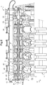
figure 5 , une vue en coupe partielle de côté d'un moteur à combustion conforme à l'invention. - Les éléments présents dans plusieurs figures distinctes sont affectés d'une seule et même référence.
- Comme déjà évoqué, l'invention se rapporte à un moteur à combustion comportant au moins un carter moteur de type sec.
- Tel que représenté à la
figure 1 , un tel moteur à combustion 1 comporte un bloc "haut moteur" 14 équipé d'au moins d'une culasse et d'au moins un cylindre à l'intérieur duquel au moins un piston se déplace alternativement en translation. - Classiquement un tel moteur à combustion 1 comporte également un bloc "bas moteur" comportant au moins un vilebrequin 4 et au moins un carter moteur 2 permettant de définir un logement de guidage 3 pour guider en rotation le vilebrequin 4 autour d'un axe de rotation V. Un tel au moins un carter moteur 2 est de type sec car le fluide de lubrification 5 est constamment pompé en dehors du logement de guidage 3 au moyen d'au moins deux pompes 7, 8.
- Par ailleurs, ces au moins deux pompes 7, 8 sont agencées de manière coaxiale pour définir un train de pompes 10 et permettre une aspiration simultanée du fluide de lubrification 5 dans différents compartiments du (ou des) carter(s) moteur 2 et/ou dans le bloc haut moteur 14 et le (ou les) carter(s) moteur 2.
- Une canalisation 11 permet alors d'acheminer le fluide de lubrification 5 depuis le (ou les) carter(s) moteur 2 vers le train de pompes 10 puis vers un réservoir 6 séparé. Une autre pompe 29 distincte des au moins deux pompes 7, 8 permet alors ensuite de réacheminer le fluide de lubrification 5 au travers d'une canalisation d'alimentation 19 vers par exemple le bloc haut moteur 14.
- Dans un mode de réalisation, une canalisation 16 permet quant à elle de réinjecter les gaz 15 dans le (ou les) carter(s) moteur 2.
- Telles que représentées aux
figures 2 à 4 , les au moins deux pompes 7, 8 formant le train de pompes 10 sont directement logées dans un alésage cylindrique 26 du (ou des) carter(s) moteur 2. Un tel alésage cylindrique 26 est généralement réalisé par usinage du (ou des) carter(s) moteur 2. Par exemple un tel usinage peut consister en une opération de tournage, de fraisage ou de perçage du (ou des) carter(s) moteur 2. - De plus, de telles pompes 7, 8 comportent respectivement chacune un rotor intérieur 17, 18 à lobes et un rotor extérieur à lobes 27, 28. De tels rotors intérieurs 17, 18 à lobes sont alors mobiles en rotation autour d'un premier axe de rotation R1 et les rotors extérieurs à lobes 27, 28 sont quant à eux mobiles en rotation autour d'un second axe de rotation R2 agencé parallèlement par rapport au premier axe de rotation R1.
- Tel que représenté à la
figure 2 , l'alésage cylindrique 26 comporte quant à lui un axe R qui est avantageusement agencé parallèlement à l'axe V du vilebrequin 4. Le moteur à combustion 1 comporte alors un arbre d'entraînement commun 20 entraîné en rotation autour du premier axe de rotation R1. Cet arbre d'entraînement commun 20 est alors solidarisé avec les rotors intérieurs 17, 18 à lobes du train de pompes 10 qui entraînent à leur tour les rotors extérieurs 27, 28 à lobes. - De plus, cet arbre d'entraînement commun 20 peut se décomposer en un arbre intérieur 30 menant et un arbre extérieur 31 creux entraîné en rotation par l'arbre intérieur 30. Un tel agencement de l'arbre d'entraînement commun 20 en deux parties distinctes peut notamment permettre d'adapter et d'absorber les vibrations en torsion d'une chaîne cinématique de transmission d'un mouvement de rotation permettant par exemple la traction, la propulsion et/ou la sustentation dans les airs d'un véhicule sur lequel est rapporté un tel moteur à combustion 1.
- Des joints toriques 38 peuvent être agencés au niveau d'une zone médiane 37 de l'arbre intérieur 30 pour permettre d'une part un centrage radial de l'arbre intérieur 30 par rapport à l'arbre extérieur 31 et d'autre part d'amortir d'éventuelles vibrations suivant une direction radiale entre l'arbre intérieur 30 et l'arbre extérieur 31. Un tel agencement permet ainsi d'éviter les frottements mécaniques et l'usure qui en résulterait.
- Par ailleurs, un tel arbre d'entraînement commun 20 est entraîné en rotation via une couronne dentée non représentée engrenant avec un pignon d'entraînement 32 solidarisé à l'arbre intérieur 30 au niveau d'une extrémité proximale 33 de cet arbre intérieur 30.
- L'arbre intérieur 30 et l'arbre extérieur 31 sont solidarisés entre eux au niveau d'une extrémité distale 34 de cet arbre intérieur 30. Une telle solidarisation peut par exemple être réalisée au moyen de cannelures de formes complémentaires réalisées entre l'arbre intérieur 30 et l'arbre extérieur 31. De telles cannelures permettent alors de ne pas supprimer un degré de liberté en translation au niveau de l'extrémité distale 34 de l'arbre intérieur 30.
- En outre, les au moins deux pompes 7, 8 comportent un carter de pompe commun 9 comportant une face externe 12 de forme cylindrique complémentaire à la forme interne de l'alésage cylindrique 26. Une portion centrale 13 de ce carter de pompe commun 9 permet alors de définir une chambre d'aspiration commune 21 et une chambre de refoulement commune 22 du mélange formé par le fluide de lubrification et de gaz entre chacune des deux pompes 7, 8.
- Tel que représenté à la
figure 2 , un tel carter de pompe commun 9 est positionné axialement sur l'axe R de l'alésage cylindrique 26 de manière à faire correspondre d'une part au moins un perçage d'aspiration 23 ménagé dans un carter moteur 2 avec la chambre d'aspiration commune 21 et d'autre part au moins un perçage de refoulement 25 avec la chambre de refoulement commune 22. - Tel que représenté à la
figure 5 , un tel perçage d'aspiration 23 permet de mettre en communication hydraulique le logement de guidage 3 avec la chambre d'aspiration commune 21 du carter de pompe commun 9. Le perçage de refoulement 25 permet quant à lui de mettre en communication hydraulique la chambre de refoulement commune 22 du carter de pompe commun 9 avec une rampe de refoulement commune 24. Une telle rampe de refoulement commune 24 est alors agencée sensiblement parallèlement par rapport à l'axe R de l'alésage cylindrique 26. - Selon une caractéristique avantageuse de l'invention, le perçage d'aspiration 23 et le perçage de refoulement 25 correspondant d'un carter de pompe commun 9 peuvent être agencés sensiblement coaxialement entre eux et être réalisés en une seule opération de perçage du (ou des) carter(s) moteur 2 depuis l'extérieur du (ou des) carter(s) moteur 2. Un bouchon 50 permet alors de refermer de manière étanche un orifice 49 laissé ouvert lors du perçage du (ou des) carter(s) moteur 2.
- Au surplus tel que représenté à la
figure 3 , le train de pompes 10 peut comporter au moins un palier de guidage 40 en rotation permettant de guider en rotation l'arbre extérieur 31 autour du premier axe de rotation R1 par rapport au carter de pompe commun 9. - Un tel palier de guidage 40 peut alors être formé par la mise en regard de deux bagues réalisées dans un matériau à faible coefficient de frottement tel que notamment du bronze auto lubrifié, du polytétrafluoroéthylène (PTFE) ou tout autre matériau. Une première bague est alors solidarisée avec l'arbre extérieur 31 et une deuxième bague est solidarisée avec le carter de pompe commun 9.
- Tel que représenté à la
figure 4 , le train de pompes 10 peut comporter quatre ensembles de deux pompes 7, 8 agencés coaxialement sur le second axe de rotation R2. Chaque ensemble permet par exemple de pomper le mélange fluide de lubrification/gaz 5,15 contenu dans une chambre du carter moteur 2 apte à accueillir au moins une bielle du vilebrequin 4. Chaque ensemble de deux pompes 7, 8 est alors isolé hydrauliquement d'un ensemble de deux pompes 7, 8 juxtaposé au moyen d'une plaque de séparation 44 rapportée de part et d'autre du carter de pompe commun 9. - Une telle plaque de séparation entre deux ensembles de deux pompes 7, 8 peut par ailleurs comporter des canaux de lubrification destinés à réaliser une bonne lubrification au niveau des surfaces en contact avec les rotors intérieurs 17, 18 à lobes et les rotors extérieurs à lobes 27, 28.
- En outre, des pièces de liaison extrémales 41, 42 permettent quant à elles de positionner axialement avec précision le train de pompes 10 à l'intérieur de l'alésage cylindrique 26. De telles pièces de liaison extrémales 41, 42 permettent également d'immobiliser en rotation le ou les carter(s) de pompe commun 9 par rapport au(x) carter(s) moteur 2. De telles pièces de liaison extrémales 41, 42 peuvent ainsi être solidarisées en liaison de type encastrement avec le (ou les) carter(s) moteur 2 au moyen de vis 45.
- Dans le cas particulier où un train de pompes comporte plusieurs ensembles de deux pompes 7, 8 juxtaposés et donc plusieurs carters de pompe commun 9 juxtaposés, des ergots de formes complémentaires permettent alors d'immobiliser en rotation chaque carter de pompe commun 9 avec un autre carter de pompe commun 9 juxtaposé. Ainsi, les pièces de liaison extrémales 41, 42 permettent alors d'immobiliser en rotation un ensemble formé par les différents carters de pompe commun 9 juxtaposés par rapport à l'alésage cylindrique 26 dans lequel cet ensemble est agencé.
- Enfin tel que représenté à la
figure 5 , chaque rotor intérieur 17, 18 à lobes du train de pompes 10 comporte une face interne 35 coopérant avec une face externe 36 de l'arbre d'entraînement commun 20. Ces faces interne 35 et externe 36 sont ainsi agencées en regard pour permettre la transmission du mouvement de rotation de l'arbre extérieur 31 autour du premier axe de rotation R1 à chacun des rotors intérieurs 17, 18 à lobes. - Par ailleurs, ces faces interne 35 et externe 36 peuvent par exemple être de formes complémentaires à section polygonale ou encore elles peuvent présenter des cannelures aptes à coopérer entre elles de manière complémentaire.
- Naturellement, la présente invention est sujette à de nombreuses variations quant à sa mise en oeuvre. Bien que plusieurs modes de réalisation aient été décrits, on comprend bien qu'il n'est pas concevable d'identifier de manière exhaustive tous les modes possibles. Il est bien sûr envisageable de remplacer un moyen décrit par un moyen équivalent sans sortir du cadre de la présente invention.
Claims (10)
- Moteur à combustion (1) comportant au moins un carter moteur (2) permettant de définir un logement de guidage (3) dans lequel au moins un vilebrequin (4) est guidé en rotation autour d'un axe de rotation V et lubrifié par un fluide de lubrification (5), ledit au moins un carter moteur (2) étant de type "sec", un tel moteur à combustion (1) comportant :• un réservoir (6) de fluide de lubrification (5) séparé dudit au moins un carter moteur (2),• au moins deux pompes (7, 8) formant un train de pompes (10) coaxiales et permettant de pomper un mélange formé par le fluide de lubrification (5) et des gaz (15) au moins au niveau dudit au moins un carter moteur (2), lesdites au moins deux pompes (7, 8) comportent respectivement chacune un rotor intérieur (17, 18) à lobes et un rotor extérieur (27, 28) à lobes, ledit rotor intérieur (17, 18) à lobes étant mobile en rotation autour d'un premier axe de rotation R1 et ledit rotor extérieur (27, 28) à lobes étant mobile en rotation autour d'un second axe de rotation R2 parallèle audit premier axe de rotation R1, chaque rotor intérieur (17, 18) à lobes dudit train de pompes (10) étant entraîné en rotation par un arbre d'entraînement commun (20) mobile en rotation autour dudit premier axe de rotation R1, chaque rotor extérieur (27, 28) à lobes dudit train de pompes (10) étant entraîné en rotation par un rotor intérieur (17, 18) à lobes dudit train de pompes (10) et ledit train de pompes (10) étant rapporté dans un alésage cylindrique (26) dudit au moins un carter moteur (2), ledit alésage cylindrique (26) comportant un axe R confondu avec ledit second axe de rotation R2 et distinct dudit premier axe de rotation R1, et• au moins une canalisation (11) permettant de mettre en communication fluidique ledit au moins un carter moteur (2), lesdites au moins deux pompes (7, 8) et ledit réservoir (6) de fluide de lubrification (5),caractérisé en ce que ledit arbre d'entraînement commun (20) comporte un arbre intérieur (30) menant et un arbre extérieur (31) creux entraîné par ledit arbre intérieur (30), lesdits arbres intérieur (30) et extérieur (31) étant agencés coaxialement l'un par rapport à l'autre.
- Moteur selon la revendication 1,
caractérisé en ce que ledit axe R dudit alésage cylindrique (26) est agencé parallèlement audit axe de rotation V dudit au moins un vilebrequin (4). - Moteur selon l'une quelconque des revendications 1 à 2,
caractérisé en ce que lesdites au moins deux pompes (7, 8) comportent un carter de pompe commun (9) comprenant une face externe (12) de forme complémentaire à celle dudit alésage cylindrique (26) dudit au moins un carter moteur (2), ledit carter de pompe commun (9) étant immobilisé en rotation par rapport audit alésage cylindrique (26), ledit carter de pompe commun (9) comportant une portion centrale (13) permettant de définir une chambre d'aspiration commune (21) et une chambre de refoulement commune (22) dudit mélange formé par ledit fluide de lubrification et de gaz pour lesdites au moins deux pompes (7, 8). - Moteur selon la revendication 3,
caractérisé en ce que ledit au moins un carter moteur (2) comporte au moins un perçage d'aspiration (23), chacun desdits au moins un perçage d'aspiration (23) permettant de mettre en communication hydraulique ledit logement de guidage (3) dudit au moins un carter moteur (2) avec ladite chambre d'aspiration commune (21) dudit carter de pompe commun (9). - Moteur selon l'une quelconque des revendications 1 à 4,
caractérisé en ce que ledit au moins un carter moteur (2) comporte une rampe de refoulement commune (24) dudit mélange formé par le fluide de lubrification et de gaz, ladite rampe de refoulement commune (24) étant agencée sensiblement parallèlement par rapport audit axe R dudit alésage cylindrique (26). - Moteur selon les revendications 3 et 5,
caractérisé en ce que ledit au moins un carter moteur (2) comporte au moins un perçage de refoulement (25), chacun desdits au moins un perçage de refoulement (25) permettant de mettre en communication hydraulique ladite chambre de refoulement commune (22) dudit carter de pompe commun (9) avec ladite rampe de roulement commune (24). - Moteur selon la revendication 1,
caractérisé en ce qu'un organe d'entraînement (32) est solidarisé en liaison de type encastrement avec ledit arbre intérieur (30) au niveau d'une extrémité proximale (33) dudit arbre intérieur (30), lesdits arbres intérieur (30) et extérieur (31) étant solidarisés entre eux en liaison de type encastrement au niveau d'une extrémité distale (34) dudit arbre intérieur (30). - Moteur selon l'une quelconque des revendications 1 à 7,
caractérisé en ce que ledit arbre d'entraînement commun (20) comporte une capacité de déformation élastique en torsion. - Moteur selon l'une quelconque des revendications 1 à 8,
caractérisé en ce que chaque rotor intérieur (17) à lobes dudit train de pompes (10) comporte une face interne (35) coopérant avec une face externe (36) dudit arbre d'entraînement commun (20), lesdites faces interne (35) et externe (36) en regard étant de formes complémentaires à section polygonale. - Moteur selon l'une quelconque des revendications 1 à 9,
caractérisé en ce que ledit train de pompes (10) comporte au moins un palier de guidage (40) en rotation suivant ledit premier axe de rotation R1, ledit au moins un palier de guidage (40) étant agencé coaxialement avec ledit arbre d'entraînement commun (20).
Priority Applications (2)
| Application Number | Priority Date | Filing Date | Title |
|---|---|---|---|
| PL17204484T PL3492715T3 (pl) | 2017-11-29 | 2017-11-29 | Silnik spalinowy zawierający co najmniej jedną skrzynię korbową typu suchego |
| EP17204484.4A EP3492715B1 (fr) | 2017-11-29 | 2017-11-29 | Moteur à combustion comportant au moins un carter moteur de type sec |
Applications Claiming Priority (1)
| Application Number | Priority Date | Filing Date | Title |
|---|---|---|---|
| EP17204484.4A EP3492715B1 (fr) | 2017-11-29 | 2017-11-29 | Moteur à combustion comportant au moins un carter moteur de type sec |
Publications (2)
| Publication Number | Publication Date |
|---|---|
| EP3492715A1 true EP3492715A1 (fr) | 2019-06-05 |
| EP3492715B1 EP3492715B1 (fr) | 2021-05-12 |
Family
ID=60543389
Family Applications (1)
| Application Number | Title | Priority Date | Filing Date |
|---|---|---|---|
| EP17204484.4A Active EP3492715B1 (fr) | 2017-11-29 | 2017-11-29 | Moteur à combustion comportant au moins un carter moteur de type sec |
Country Status (2)
| Country | Link |
|---|---|
| EP (1) | EP3492715B1 (fr) |
| PL (1) | PL3492715T3 (fr) |
Citations (6)
| Publication number | Priority date | Publication date | Assignee | Title |
|---|---|---|---|---|
| US3619093A (en) * | 1968-11-18 | 1971-11-09 | Hohenzollern Huettenverwalt | Gear-type hydraulic machine |
| GB2205611A (en) | 1987-06-09 | 1988-12-14 | Austin Rover Group | A pump assembly |
| JPH03237207A (ja) | 1989-10-31 | 1991-10-23 | Isuzu Motors Ltd | エンジンの潤滑装置 |
| US5580232A (en) * | 1995-05-04 | 1996-12-03 | Kobelco Compressors (America), Inc. | Rotor assembly having a slip joint in the shaft assembly |
| JP2006132342A (ja) | 2004-11-02 | 2006-05-25 | Honda Motor Co Ltd | オイルポンプユニット |
| DE102010011477A1 (de) | 2010-03-16 | 2011-09-22 | Audi Ag | Brennkraftmaschine mit Trockensumpfschmierung undmehrstufiger integrierter Ölpumpe |
-
2017
- 2017-11-29 PL PL17204484T patent/PL3492715T3/pl unknown
- 2017-11-29 EP EP17204484.4A patent/EP3492715B1/fr active Active
Patent Citations (6)
| Publication number | Priority date | Publication date | Assignee | Title |
|---|---|---|---|---|
| US3619093A (en) * | 1968-11-18 | 1971-11-09 | Hohenzollern Huettenverwalt | Gear-type hydraulic machine |
| GB2205611A (en) | 1987-06-09 | 1988-12-14 | Austin Rover Group | A pump assembly |
| JPH03237207A (ja) | 1989-10-31 | 1991-10-23 | Isuzu Motors Ltd | エンジンの潤滑装置 |
| US5580232A (en) * | 1995-05-04 | 1996-12-03 | Kobelco Compressors (America), Inc. | Rotor assembly having a slip joint in the shaft assembly |
| JP2006132342A (ja) | 2004-11-02 | 2006-05-25 | Honda Motor Co Ltd | オイルポンプユニット |
| DE102010011477A1 (de) | 2010-03-16 | 2011-09-22 | Audi Ag | Brennkraftmaschine mit Trockensumpfschmierung undmehrstufiger integrierter Ölpumpe |
Also Published As
| Publication number | Publication date |
|---|---|
| PL3492715T3 (pl) | 2021-11-22 |
| EP3492715B1 (fr) | 2021-05-12 |
Similar Documents
| Publication | Publication Date | Title |
|---|---|---|
| CA2640208C (fr) | Carter intermediaire de turboreacteur et turboreacteur | |
| CA2922034C (fr) | Ensemble rotatif comprenant un organe de transmission et un systeme de distribution d'huile | |
| CA2943732C (fr) | Ensemble de transmission comprenant un organe de transmission et un systeme de distribution d'huile | |
| CA2952506C (fr) | Dispositif et procede de lubrification d'un palier a roulement de turbomachine | |
| EP2724004B1 (fr) | Moteur à combustion interne avec transmission à calage variable | |
| FR2491134A1 (fr) | Turbine a gaz pour vehicule automobile | |
| BE1016961A3 (fr) | Perfectionnements du moteur a rapport volumetrique variable. | |
| CA2987117C (fr) | Moteur a combustion comportant au moins un carter moteur de type sec | |
| EP3492715B1 (fr) | Moteur à combustion comportant au moins un carter moteur de type sec | |
| FR2831934A1 (fr) | Boite de transmission basculante avec dispositif de rattrapage de jeu selon l'axe de basculement | |
| EP4023909B1 (fr) | Porte-satellites pour un reducteur mecanique de turbomachine d aeronef | |
| FR3057609A1 (fr) | Moteur a combustion comportant au moins un carter moteur de type sec | |
| FR2733008A1 (fr) | Installation pour transferer du carburant d'un reservoir vers le moteur d'un vehicule automobile, par une pompe a engrenages ou a transfert et une pompe a cellules semi-rotative | |
| WO2014048838A1 (fr) | Différentiel intégrant un appareil hydraulique | |
| FR2486588A1 (fr) | Moteur a combustion interne a cinq cylindres en ligne, equipe d'un arbre d'equilibrage | |
| FR3096072A1 (fr) | Turbomachine comprenant un amortisseur de palier d’arbre à viscance variable | |
| EP3134286B1 (fr) | Ensemble d'entraînement pour un arbre moteur d'un véhicule automobile | |
| EP0487393B1 (fr) | Mécanisme à fluide sous pression dit "à came tournante" | |
| FR3081184A1 (fr) | Moteur rotatif a conduite centrale du rotor avec axe moteur rectiligne | |
| FR3075898A1 (fr) | Arbre de transmission pour une turbomachine | |
| FR3078749A1 (fr) | Coussinet de palier de vilebrequin et systeme de lubrification associe | |
| EP4279758A1 (fr) | Joint de cardan lubrifié | |
| FR3022951A1 (fr) | Pompe a deux etages, prevue notamment comme pompe principale d'alimentation d'un moteur d'avion en carburant | |
| FR2628479A1 (fr) | Assemblage piston et cylindre a mouvement alternatif pour moteurs a combustion interne et equivalent | |
| EP4293203B1 (fr) | Module de lubrification d'un poste de lubrification d'une turbomachine |
Legal Events
| Date | Code | Title | Description |
|---|---|---|---|
| PUAI | Public reference made under article 153(3) epc to a published international application that has entered the european phase |
Free format text: ORIGINAL CODE: 0009012 |
|
| STAA | Information on the status of an ep patent application or granted ep patent |
Free format text: STATUS: THE APPLICATION HAS BEEN PUBLISHED |
|
| AK | Designated contracting states |
Kind code of ref document: A1 Designated state(s): AL AT BE BG CH CY CZ DE DK EE ES FI FR GB GR HR HU IE IS IT LI LT LU LV MC MK MT NL NO PL PT RO RS SE SI SK SM TR |
|
| AX | Request for extension of the european patent |
Extension state: BA ME |
|
| STAA | Information on the status of an ep patent application or granted ep patent |
Free format text: STATUS: REQUEST FOR EXAMINATION WAS MADE |
|
| 17P | Request for examination filed |
Effective date: 20190829 |
|
| RBV | Designated contracting states (corrected) |
Designated state(s): AL AT BE BG CH CY CZ DE DK EE ES FI FR GB GR HR HU IE IS IT LI LT LU LV MC MK MT NL NO PL PT RO RS SE SI SK SM TR |
|
| GRAP | Despatch of communication of intention to grant a patent |
Free format text: ORIGINAL CODE: EPIDOSNIGR1 |
|
| RIC1 | Information provided on ipc code assigned before grant |
Ipc: F01M 1/02 20060101AFI20210121BHEP Ipc: F01M 11/00 20060101ALN20210121BHEP Ipc: F02B 75/06 20060101ALI20210121BHEP Ipc: F01M 1/12 20060101ALI20210121BHEP |
|
| STAA | Information on the status of an ep patent application or granted ep patent |
Free format text: STATUS: GRANT OF PATENT IS INTENDED |
|
| INTG | Intention to grant announced |
Effective date: 20210225 |
|
| GRAS | Grant fee paid |
Free format text: ORIGINAL CODE: EPIDOSNIGR3 |
|
| GRAA | (expected) grant |
Free format text: ORIGINAL CODE: 0009210 |
|
| STAA | Information on the status of an ep patent application or granted ep patent |
Free format text: STATUS: THE PATENT HAS BEEN GRANTED |
|
| AK | Designated contracting states |
Kind code of ref document: B1 Designated state(s): AL AT BE BG CH CY CZ DE DK EE ES FI FR GB GR HR HU IE IS IT LI LT LU LV MC MK MT NL NO PL PT RO RS SE SI SK SM TR |
|
| REG | Reference to a national code |
Ref country code: GB Ref legal event code: FG4D Free format text: NOT ENGLISH |
|
| REG | Reference to a national code |
Ref country code: CH Ref legal event code: EP |
|
| REG | Reference to a national code |
Ref country code: DE Ref legal event code: R096 Ref document number: 602017038459 Country of ref document: DE |
|
| REG | Reference to a national code |
Ref country code: IE Ref legal event code: FG4D Free format text: LANGUAGE OF EP DOCUMENT: FRENCH |
|
| REG | Reference to a national code |
Ref country code: AT Ref legal event code: REF Ref document number: 1392298 Country of ref document: AT Kind code of ref document: T Effective date: 20210615 |
|
| REG | Reference to a national code |
Ref country code: LT Ref legal event code: MG9D |
|
| REG | Reference to a national code |
Ref country code: AT Ref legal event code: MK05 Ref document number: 1392298 Country of ref document: AT Kind code of ref document: T Effective date: 20210512 |
|
| REG | Reference to a national code |
Ref country code: NL Ref legal event code: MP Effective date: 20210512 |
|
| PG25 | Lapsed in a contracting state [announced via postgrant information from national office to epo] |
Ref country code: HR Free format text: LAPSE BECAUSE OF FAILURE TO SUBMIT A TRANSLATION OF THE DESCRIPTION OR TO PAY THE FEE WITHIN THE PRESCRIBED TIME-LIMIT Effective date: 20210512 Ref country code: AT Free format text: LAPSE BECAUSE OF FAILURE TO SUBMIT A TRANSLATION OF THE DESCRIPTION OR TO PAY THE FEE WITHIN THE PRESCRIBED TIME-LIMIT Effective date: 20210512 Ref country code: BG Free format text: LAPSE BECAUSE OF FAILURE TO SUBMIT A TRANSLATION OF THE DESCRIPTION OR TO PAY THE FEE WITHIN THE PRESCRIBED TIME-LIMIT Effective date: 20210812 Ref country code: LT Free format text: LAPSE BECAUSE OF FAILURE TO SUBMIT A TRANSLATION OF THE DESCRIPTION OR TO PAY THE FEE WITHIN THE PRESCRIBED TIME-LIMIT Effective date: 20210512 Ref country code: FI Free format text: LAPSE BECAUSE OF FAILURE TO SUBMIT A TRANSLATION OF THE DESCRIPTION OR TO PAY THE FEE WITHIN THE PRESCRIBED TIME-LIMIT Effective date: 20210512 |
|
| PG25 | Lapsed in a contracting state [announced via postgrant information from national office to epo] |
Ref country code: SE Free format text: LAPSE BECAUSE OF FAILURE TO SUBMIT A TRANSLATION OF THE DESCRIPTION OR TO PAY THE FEE WITHIN THE PRESCRIBED TIME-LIMIT Effective date: 20210512 Ref country code: RS Free format text: LAPSE BECAUSE OF FAILURE TO SUBMIT A TRANSLATION OF THE DESCRIPTION OR TO PAY THE FEE WITHIN THE PRESCRIBED TIME-LIMIT Effective date: 20210512 Ref country code: PT Free format text: LAPSE BECAUSE OF FAILURE TO SUBMIT A TRANSLATION OF THE DESCRIPTION OR TO PAY THE FEE WITHIN THE PRESCRIBED TIME-LIMIT Effective date: 20210913 Ref country code: NO Free format text: LAPSE BECAUSE OF FAILURE TO SUBMIT A TRANSLATION OF THE DESCRIPTION OR TO PAY THE FEE WITHIN THE PRESCRIBED TIME-LIMIT Effective date: 20210812 Ref country code: IS Free format text: LAPSE BECAUSE OF FAILURE TO SUBMIT A TRANSLATION OF THE DESCRIPTION OR TO PAY THE FEE WITHIN THE PRESCRIBED TIME-LIMIT Effective date: 20210912 Ref country code: LV Free format text: LAPSE BECAUSE OF FAILURE TO SUBMIT A TRANSLATION OF THE DESCRIPTION OR TO PAY THE FEE WITHIN THE PRESCRIBED TIME-LIMIT Effective date: 20210512 Ref country code: GR Free format text: LAPSE BECAUSE OF FAILURE TO SUBMIT A TRANSLATION OF THE DESCRIPTION OR TO PAY THE FEE WITHIN THE PRESCRIBED TIME-LIMIT Effective date: 20210813 |
|
| PG25 | Lapsed in a contracting state [announced via postgrant information from national office to epo] |
Ref country code: NL Free format text: LAPSE BECAUSE OF FAILURE TO SUBMIT A TRANSLATION OF THE DESCRIPTION OR TO PAY THE FEE WITHIN THE PRESCRIBED TIME-LIMIT Effective date: 20210512 |
|
| PG25 | Lapsed in a contracting state [announced via postgrant information from national office to epo] |
Ref country code: SM Free format text: LAPSE BECAUSE OF FAILURE TO SUBMIT A TRANSLATION OF THE DESCRIPTION OR TO PAY THE FEE WITHIN THE PRESCRIBED TIME-LIMIT Effective date: 20210512 Ref country code: SK Free format text: LAPSE BECAUSE OF FAILURE TO SUBMIT A TRANSLATION OF THE DESCRIPTION OR TO PAY THE FEE WITHIN THE PRESCRIBED TIME-LIMIT Effective date: 20210512 Ref country code: CZ Free format text: LAPSE BECAUSE OF FAILURE TO SUBMIT A TRANSLATION OF THE DESCRIPTION OR TO PAY THE FEE WITHIN THE PRESCRIBED TIME-LIMIT Effective date: 20210512 Ref country code: DK Free format text: LAPSE BECAUSE OF FAILURE TO SUBMIT A TRANSLATION OF THE DESCRIPTION OR TO PAY THE FEE WITHIN THE PRESCRIBED TIME-LIMIT Effective date: 20210512 Ref country code: EE Free format text: LAPSE BECAUSE OF FAILURE TO SUBMIT A TRANSLATION OF THE DESCRIPTION OR TO PAY THE FEE WITHIN THE PRESCRIBED TIME-LIMIT Effective date: 20210512 Ref country code: RO Free format text: LAPSE BECAUSE OF FAILURE TO SUBMIT A TRANSLATION OF THE DESCRIPTION OR TO PAY THE FEE WITHIN THE PRESCRIBED TIME-LIMIT Effective date: 20210512 Ref country code: ES Free format text: LAPSE BECAUSE OF FAILURE TO SUBMIT A TRANSLATION OF THE DESCRIPTION OR TO PAY THE FEE WITHIN THE PRESCRIBED TIME-LIMIT Effective date: 20210512 |
|
| REG | Reference to a national code |
Ref country code: DE Ref legal event code: R097 Ref document number: 602017038459 Country of ref document: DE |
|
| PLBE | No opposition filed within time limit |
Free format text: ORIGINAL CODE: 0009261 |
|
| STAA | Information on the status of an ep patent application or granted ep patent |
Free format text: STATUS: NO OPPOSITION FILED WITHIN TIME LIMIT |
|
| 26N | No opposition filed |
Effective date: 20220215 |
|
| PG25 | Lapsed in a contracting state [announced via postgrant information from national office to epo] |
Ref country code: IS Free format text: LAPSE BECAUSE OF FAILURE TO SUBMIT A TRANSLATION OF THE DESCRIPTION OR TO PAY THE FEE WITHIN THE PRESCRIBED TIME-LIMIT Effective date: 20210912 Ref country code: AL Free format text: LAPSE BECAUSE OF FAILURE TO SUBMIT A TRANSLATION OF THE DESCRIPTION OR TO PAY THE FEE WITHIN THE PRESCRIBED TIME-LIMIT Effective date: 20210512 |
|
| PG25 | Lapsed in a contracting state [announced via postgrant information from national office to epo] |
Ref country code: MC Free format text: LAPSE BECAUSE OF FAILURE TO SUBMIT A TRANSLATION OF THE DESCRIPTION OR TO PAY THE FEE WITHIN THE PRESCRIBED TIME-LIMIT Effective date: 20210512 |
|
| REG | Reference to a national code |
Ref country code: CH Ref legal event code: PL |
|
| PG25 | Lapsed in a contracting state [announced via postgrant information from national office to epo] |
Ref country code: LU Free format text: LAPSE BECAUSE OF NON-PAYMENT OF DUE FEES Effective date: 20211129 Ref country code: BE Free format text: LAPSE BECAUSE OF NON-PAYMENT OF DUE FEES Effective date: 20211130 |
|
| REG | Reference to a national code |
Ref country code: BE Ref legal event code: MM Effective date: 20211130 |
|
| PG25 | Lapsed in a contracting state [announced via postgrant information from national office to epo] |
Ref country code: IE Free format text: LAPSE BECAUSE OF NON-PAYMENT OF DUE FEES Effective date: 20211129 |
|
| PG25 | Lapsed in a contracting state [announced via postgrant information from national office to epo] |
Ref country code: CY Free format text: LAPSE BECAUSE OF FAILURE TO SUBMIT A TRANSLATION OF THE DESCRIPTION OR TO PAY THE FEE WITHIN THE PRESCRIBED TIME-LIMIT Effective date: 20210512 |
|
| P01 | Opt-out of the competence of the unified patent court (upc) registered |
Effective date: 20230530 |
|
| PG25 | Lapsed in a contracting state [announced via postgrant information from national office to epo] |
Ref country code: LI Free format text: LAPSE BECAUSE OF NON-PAYMENT OF DUE FEES Effective date: 20220630 Ref country code: HU Free format text: LAPSE BECAUSE OF FAILURE TO SUBMIT A TRANSLATION OF THE DESCRIPTION OR TO PAY THE FEE WITHIN THE PRESCRIBED TIME-LIMIT; INVALID AB INITIO Effective date: 20171129 Ref country code: CH Free format text: LAPSE BECAUSE OF NON-PAYMENT OF DUE FEES Effective date: 20220630 |
|
| PG25 | Lapsed in a contracting state [announced via postgrant information from national office to epo] |
Ref country code: MK Free format text: LAPSE BECAUSE OF FAILURE TO SUBMIT A TRANSLATION OF THE DESCRIPTION OR TO PAY THE FEE WITHIN THE PRESCRIBED TIME-LIMIT Effective date: 20210512 |
|
| PG25 | Lapsed in a contracting state [announced via postgrant information from national office to epo] |
Ref country code: MT Free format text: LAPSE BECAUSE OF FAILURE TO SUBMIT A TRANSLATION OF THE DESCRIPTION OR TO PAY THE FEE WITHIN THE PRESCRIBED TIME-LIMIT Effective date: 20210512 |
|
| PG25 | Lapsed in a contracting state [announced via postgrant information from national office to epo] |
Ref country code: TR Free format text: LAPSE BECAUSE OF FAILURE TO SUBMIT A TRANSLATION OF THE DESCRIPTION OR TO PAY THE FEE WITHIN THE PRESCRIBED TIME-LIMIT Effective date: 20210512 |
|
| PGFP | Annual fee paid to national office [announced via postgrant information from national office to epo] |
Ref country code: DE Payment date: 20251119 Year of fee payment: 9 |
|
| PGFP | Annual fee paid to national office [announced via postgrant information from national office to epo] |
Ref country code: GB Payment date: 20251121 Year of fee payment: 9 |
|
| PGFP | Annual fee paid to national office [announced via postgrant information from national office to epo] |
Ref country code: IT Payment date: 20251125 Year of fee payment: 9 |
|
| PGFP | Annual fee paid to national office [announced via postgrant information from national office to epo] |
Ref country code: FR Payment date: 20251126 Year of fee payment: 9 |
|
| PGFP | Annual fee paid to national office [announced via postgrant information from national office to epo] |
Ref country code: PL Payment date: 20251023 Year of fee payment: 9 |