EP3492683A1 - Door and door arrangement - Google Patents
Door and door arrangement Download PDFInfo
- Publication number
- EP3492683A1 EP3492683A1 EP17204377.0A EP17204377A EP3492683A1 EP 3492683 A1 EP3492683 A1 EP 3492683A1 EP 17204377 A EP17204377 A EP 17204377A EP 3492683 A1 EP3492683 A1 EP 3492683A1
- Authority
- EP
- European Patent Office
- Prior art keywords
- door
- door leaf
- doorway
- panel
- thickness direction
- Prior art date
- Legal status (The legal status is an assumption and is not a legal conclusion. Google has not performed a legal analysis and makes no representation as to the accuracy of the status listed.)
- Withdrawn
Links
Images

Classifications
-
- E—FIXED CONSTRUCTIONS
- E06—DOORS, WINDOWS, SHUTTERS, OR ROLLER BLINDS IN GENERAL; LADDERS
- E06B—FIXED OR MOVABLE CLOSURES FOR OPENINGS IN BUILDINGS, VEHICLES, FENCES OR LIKE ENCLOSURES IN GENERAL, e.g. DOORS, WINDOWS, BLINDS, GATES
- E06B5/00—Doors, windows, or like closures for special purposes; Border constructions therefor
- E06B5/10—Doors, windows, or like closures for special purposes; Border constructions therefor for protection against air-raid or other war-like action; for other protective purposes
- E06B5/18—Doors, windows, or like closures for special purposes; Border constructions therefor for protection against air-raid or other war-like action; for other protective purposes against harmful radiation
-
- E—FIXED CONSTRUCTIONS
- E05—LOCKS; KEYS; WINDOW OR DOOR FITTINGS; SAFES
- E05D—HINGES OR SUSPENSION DEVICES FOR DOORS, WINDOWS OR WINGS
- E05D15/00—Suspension arrangements for wings
- E05D15/06—Suspension arrangements for wings for wings sliding horizontally more or less in their own plane
- E05D15/10—Suspension arrangements for wings for wings sliding horizontally more or less in their own plane movable out of one plane into a second parallel plane
- E05D15/1042—Suspension arrangements for wings for wings sliding horizontally more or less in their own plane movable out of one plane into a second parallel plane with transversely moving carriage
-
- E—FIXED CONSTRUCTIONS
- E05—LOCKS; KEYS; WINDOW OR DOOR FITTINGS; SAFES
- E05D—HINGES OR SUSPENSION DEVICES FOR DOORS, WINDOWS OR WINGS
- E05D15/00—Suspension arrangements for wings
- E05D15/06—Suspension arrangements for wings for wings sliding horizontally more or less in their own plane
- E05D15/10—Suspension arrangements for wings for wings sliding horizontally more or less in their own plane movable out of one plane into a second parallel plane
- E05D15/1042—Suspension arrangements for wings for wings sliding horizontally more or less in their own plane movable out of one plane into a second parallel plane with transversely moving carriage
- E05D2015/1055—Suspension arrangements for wings for wings sliding horizontally more or less in their own plane movable out of one plane into a second parallel plane with transversely moving carriage with slanted or curved track sections or cams
-
- E—FIXED CONSTRUCTIONS
- E05—LOCKS; KEYS; WINDOW OR DOOR FITTINGS; SAFES
- E05Y—INDEXING SCHEME ASSOCIATED WITH SUBCLASSES E05D AND E05F, RELATING TO CONSTRUCTION ELEMENTS, ELECTRIC CONTROL, POWER SUPPLY, POWER SIGNAL OR TRANSMISSION, USER INTERFACES, MOUNTING OR COUPLING, DETAILS, ACCESSORIES, AUXILIARY OPERATIONS NOT OTHERWISE PROVIDED FOR, APPLICATION THEREOF
- E05Y2800/00—Details, accessories and auxiliary operations not otherwise provided for
- E05Y2800/40—Physical or chemical protection
- E05Y2800/414—Physical or chemical protection against high or low temperatures
- E05Y2800/416—Physical or chemical protection against high or low temperatures against fire
-
- E—FIXED CONSTRUCTIONS
- E05—LOCKS; KEYS; WINDOW OR DOOR FITTINGS; SAFES
- E05Y—INDEXING SCHEME ASSOCIATED WITH SUBCLASSES E05D AND E05F, RELATING TO CONSTRUCTION ELEMENTS, ELECTRIC CONTROL, POWER SUPPLY, POWER SIGNAL OR TRANSMISSION, USER INTERFACES, MOUNTING OR COUPLING, DETAILS, ACCESSORIES, AUXILIARY OPERATIONS NOT OTHERWISE PROVIDED FOR, APPLICATION THEREOF
- E05Y2900/00—Application of doors, windows, wings or fittings thereof
- E05Y2900/10—Application of doors, windows, wings or fittings thereof for buildings or parts thereof
- E05Y2900/13—Type of wing
- E05Y2900/132—Doors
- E05Y2900/134—Fire doors
Definitions
- the invention relates to doors, and particularly to doors suitable for covering doorways of a room for medical treatment or examination. Such doors are needed for example in hospitals, and they may need to have special features integrated therein so as to ensure safety.
- Doors for special purposes such as doors used in rooms for medical treatment and/or examination in hospitals, may need to have special features integrated therein.
- Such features may include one or more of a structure enabling tight closing of the door, a means for absorbing radiation generated by examination or treatment machinery such as X-rays, and a fireproof structure.
- a drawback of the known doors has been that they are expensive to manufacture. This is partially due to their case-specific features, but largely also due to that they need to be tailored and that they are unique. It has come up a need for a new solution reducing manufacturing costs of the door.
- the object of the invention is to provide a new door leaf solution.
- An object is particularly to alleviate one or more of the above defined problems of prior art and/or problems discussed or implied elsewhere in the description.
- An object is particularly to provide a new door leaf solution suitable for covering a doorway of a room for medical treatment or examination.
- the door leaf which can be manufactured cost-effectively, and that it can be such that it includes one or more special features such as a structure enabling tight closing of the door, a means for absorbing radiation generated by examination or treatment machinery such as X-rays, and a fireproof structure, for example.
- the door leaf comprising a first door panel and a second door panel, wherein the first and second door panel are parallel to each other and superimposed in their thickness direction and connected to each other movably in said thickness direction towards each other and away from each other, in particular a limited range of movement back and forth, and wherein the door leaf comprises one or more springs loadable to push the door panels to move in said thickness direction away from each other.
- first and second door panel are connected to each other immovably in directions orthogonal to said thickness direction.
- the one or more springs are loadable by moving the door panels towards each other.
- said limited range of movement is 0.5 cm - 5 cm long, more preferably 1 cm - 3 cm long, as measured in said thickness direction.
- the door leaf comprises means for limiting the range of movement of the door panel in said thickness direction towards each other.
- each said door panel comprises a first skin made of sheet metal and a second skin made of sheet metal, and a space between said first and second skin.
- the door leaf comprises a seal provided on the second door panel for being pressed against a border of a doorway for sealing the gap between the second door panel and a border of a doorway.
- the seal is deformable by compression exerted thereon in said thickness direction.
- the seal is provided on an outer surface of the second door panel, the surface preferably facing in said thickness direction away from the second door panel.
- the seal is elastic.
- the seal is made of rubber.
- the one or more springs are arranged to elastically deform when the door panels move towards each other.
- the one or more springs are loadable by elastically deforming them.
- the one or more springs are between the first and second door panel.
- the one or more springs are loadable by compression, preferably compression in said thickness direction.
- the one or more springs are coil springs, but they can alternatively be disc springs, leaf springs, torsion springs or gas springs, for example.
- the door leaf comprises a space between the first panel and the second panel into which the first panel can at least partially move when the first and second door panel are moved in said thickness direction towards each other.
- the door leaf is a door leaf for a covering a doorway of a room for medical treatment and/or examination.
- the door leaf preferably the first panel and/or the second panel thereof, comprises at least one lead member, such as a lead plate for absorbing radiation, particularly X-ray radiation.
- the door leaf is a fire door leaf.
- the first panel and/or the second panel comprises a space containing fireproof filling, such as fire proof polyurethane material, such as polyurethane material comprising a fire retardant additive.
- the polyurethane is preferably polyurethane foam.
- the fireproof filling fills substantially the space.
- the door leaf is a sliding door leaf.
- the door leaf comprises one or more guide members for guiding the door leaf into a closed position, preferably by sliding.
- said guide members are guide runners comprised in the door leaf suitable for being guided by a guide rail mounted in proximity of the doorway such as a roller or slider.
- the guidance could operated in opposite way, namely said one or more guide members comprised in the door could comprise a guide rail suitable for receiving and for being guided by a guide runner, such as a roller or slider that is mounted in proximity of the doorway.
- the one or more guide members could comprise a hinge.
- the one or more guide runners comprised in the door leaf mentioned in the preceding paragraph extend vertically upwards and/or downwards from the door leaf.
- the one or more guide runners can comprise one or more guide runners mounted on the first door panel and/or one or more guide runners mounted on the second door panel.
- the door comprises guide means for guiding of the movement of the first and second door panel in said thickness direction towards each other and away from each other, most preferably by linear movement.
- Said guide means preferably comprise a first guide means for blocking relative movement between the first and second door panel in horizontal direction orthogonal to said thickness direction and/or a second guide means for blocking movement relative between the first and second door panel in vertical direction.
- the first guide means can comprise a guide member, such a slider, e.g. a pin, coupled with the first panel, and a guide rail that is coupled with the second panel and elongated in said thickness direction and suitable for guiding movement of the guide member, or vice versa.
- a guide member such as a slider, e.g. a pin, coupled with the first panel, and a guide rail that is coupled with the second panel and elongated in said thickness direction and suitable for guiding movement of the guide member, or vice versa.
- the door leaf comprises a positioning member provided on the first door panel, which positioning member is engageable with a counterpart provided on the border of the doorway for positioning the first door panel immovably to a position relative to the border of the doorway at least in said thickness direction when the door leaf is in closed position.
- Said positioning member is preferably operable to move back and forth for engaging and disengaging with said counterpart.
- the counterpart is preferably a counterpart opening provided on the border of the doorway, and the positioning member a bolt such as a latch bolt or dead bolt provided on the first panel.
- the door leaf comprises a handle operably connected with the bolt, whereby by actuation of the handle, the bolt can be operated.
- the one or more springs are preloaded to push the door panels to move in said thickness direction away from each other. This means that when the door panels are at the end of their range of movement away from each other, the one or more springs push the door panels to move in said thickness direction away from each other. Also in this case, the one or more springs can be loadable, i.e. further loadable, by moving the door panels towards each other. Preloading is advantageous since it eliminates undesired movement and clap of the door panels. This is particularly valuable for making movement of the door leaf smooth and quiet when the door leaf is separate from the border of the doorway.
- movement the door panels relative to each other is linear movement.
- no deformation, such as bending for instance, of the door panels occur during the movement.
- the door leaf is movable between open position and a closed position.
- the door leaf in the closed position the door leaf covers the doorway.
- it is mounted in proximity of the doorway movably between said open position and a closed position.
- the door arrangement comprises guide means for guiding the door leaf into the closed position.
- Said guide means preferably comprise one or more guide runners comprised in the door leaf, and one or more guide rails mounted in proximity of the doorway, or vice versa.
- Said guide rails are preferably shaped to guide the door leaf to move at least in said thickness direction towards the doorway.
- said guide rails are curved to guide the door leaf to move along a non-linear path, including a first section for guiding the door leaf to move in horizontal direction orthogonal to said thickness direction towards the doorway, and a second section for guiding the door leaf to move at least in said thickness direction towards the doorway to lean on the border of the opening.
- the door arrangement comprises motor-driven machinery for moving the door leaf into the closed position.
- the one or more springs are loaded to push the door panels to move in said thickness direction away from each other such that the second door panel is pressed against the border of the doorway, directly or via one or more seals provided therebetween.
- the second door panel in the closed position of the door leaf the second door panel is positioned to lean on a border of the doorway at least in said thickness direction (directly or via one or more seals provided therebetween), and the door panels positioned relative to each other i.e. such close to each other that the one or more springs are in loaded state where they push the second door panel to move in said thickness direction towards the border of the doorway, whereby the second door panel is pressed against the border of the doorway, directly or via one or more seals provided therebetween.
- the door leaf in closing of the door leaf the door leaf is arranged to move at least in said thickness direction to lean on the border of the opening (directly or via one or more seals provided therebetween), which border of the opening is arranged to block movement of the second panel in said thickness direction, and further movement of the door leaf in said thickness direction is arranged to force the door panels to move in said thickness direction towards each other such that the springs are loaded to push the second door panel to move in said thickness direction towards the border of the doorway, whereby the second door panel is pressed against the border of the doorway directly or via one or more seals provided therebetween.
- the second door panel in the closed position is positioned to lean on a border of the doorway via one or more seals provided therebetween.
- each said seal is deformed by compression exerted thereon in said thickness direction.
- the first panel when the door leaf is in closed position, the first panel is positioned such that it provides the one or more springs the reaction force needed by the one or more springs for pushing the second door panel to move in said thickness direction towards the border of the doorway.
- the arrangement comprises a positioning means for positioning the door leaf relative to a doorway in said closed position.
- the positioning means are arranged to position the first door panel to be immovable relative to the border of the doorway at least in said thickness direction when in closed position.
- the positioning means comprise a positioning member engageable with a counterpart provided on the border of the doorway for positioning the first door panel to a position immovable relative to the border of the doorway at least in said thickness direction t when the door leaf is in closed position.
- the arrangement comprises one or more seals for sealing the gap between the second door panel and a border of a doorway.
- the one or more seals can include one or more seals provided on the second door panel for being pressed against a border of a doorway and/or one or more seals provided on the border of a doorway for being pressed by the second door panel when the door leaf is in closed position.
- the doorway is a doorway of a room for medical treatment and/or examination.
- the room is then preferably a room of a hospital.
- the door leaf comprises a first door panel 3 and a second door panel 4, which first and second door panel 3,4 are parallel to each other and superimposed in their thickness direction t and connected to each other movably in said thickness direction t towards each other and away from each other, preferably a limited range of movement back and forth.
- the door leaf 1 comprises one or more springs 5, in the illustrated embodiment at least two of such springs 5, loadable to push the door panels 3,4 to move in said thickness direction t away from each other. This makes it possible to move the door leaf 1 in in a closed position as illustrated in Figure 2 .
- the second door panel 4 leans on a border 8 of the doorway 2 at least in said thickness direction, and the door panels 3,4 are positioned relative to each other that the one or more springs 5 are in loaded state where they push the second door panel 4 to move in said thickness direction t towards the border of the doorway 2, whereby the second door panel 4 is pressed against the border of the doorway 2, directly or via one or more seals 6a,6b provided therebetween.
- Each of the seals 6a,6b is preferably elastic, and can be made of rubber, for instance.
- the first panel 3 When the door leaf 1 is in closed position, the first panel 3 is positioned such that it provides the one or more springs 5 the reaction force needed by the one or more springs 5 for pushing the second door panel 4 to move in said thickness direction t towards the border of the doorway 2.
- each said door panel 3,4 comprises a first skin 3a;4a made of sheet metal and a second skin 3b;4b made of sheet metal, and a space 18 between said first and second skin 3a,3b;4a,4b.
- This construction makes it possible to use two similar or at least substantially similar panel elements, whereby manufacturing of the door leaf 1 is made simple and cheap, and panel elements used in regular doors can be used also in this special door and need for tailor-made components is reduced. This construction also makes it possible to make the door leaf 1 simply fireproof.
- the door leaf 1 is moreover preferably such that the first panel 3 and/or the second panel 4 comprises a space 16 contain a fireproof filling 17, such as a filling comprising fire proof polyurethane material, such as polyurethane material comprising a fire retardant additive.
- a fireproof filling 17 such as a filling comprising fire proof polyurethane material, such as polyurethane material comprising a fire retardant additive.
- the polyurethane is preferably polyurethane foam.
- the fireproof filling 16 preferably fills substantially the space 16.
- first and the second door panel 3,4 are connected to each other movably in said thickness direction t towards each other and away from each other, preferably a limited range of movement back and forth.
- Said limited range of movement is preferably 0.5 cm - 5 cm long, more preferably 1 cm - 3 cm long, as measured in said thickness direction t.
- the one or more springs 5 are loadable by moving the door panels 3,4 towards each other.
- the one or more springs 5 are arranged to elastically deform when the door panels 3,4 move towards each other and to elastically resist movement of the door panels towards each other.
- the one or more springs 5 are between the first and second door panel 3,4. However this is not necessary.
- the one or more springs 5 illustrated are coil springs, but it is possible to modify the construction such that instead of coil springs the one or more springs are some other kind of springs, such as disc springs, leaf springs, torsion springs or gas springs, for example.
- the one or more springs 5 are loadable by compression in said thickness direction.
- the door leaf 1 preferably comprises a seal 6a provided on the second door panel 4 for being pressed against a border 8 of a doorway 2 for sealing the gap 7 between the second door panel 4 and a border 8 of a doorway 2.
- the seal 6a is in the preferred embodiment provided on an outer surface of the second door panel 4, the surface facing in said thickness direction t away from the second door panel 4.
- Such a seal 6b can alternatively, or additionally be provided on the border of the opening 2, as disclosed in Figure 2 .
- the seal(s) 6a,6b facilitate airtight closing of the door leaf 1. This is advantageous when the door leaf 1 covers a doorway 2 of a room for medical treatment and/or examination. Airtight closing is advantageous as it prevents air flow into the room, which air flow could bring harmful gases or impurities into the room.
- the seal(s) 6a,6b is/are also advantageous when the door leaf 1 is a fire door leaf, since then the flames and/or possible gases produced in fire cannot move between rooms separated by the door leaf 1.
- Each said seal 6a,6b is preferably made of fireproof material.
- Each said seal 6a,6b is preferably such that it is deformable by compression exerted thereon in said thickness direction t. Thus, movement of the door leaf 1 into closed position can effectively seal the aforementioned gap.
- the door leaf comprises a space 18 between the first panel 3 and the second panel 4 into which the first panel can at least partially move when the first and second door panel 3,4 are moved in said thickness direction t towards each other.
- This space is advantageous when the door leaf 1 is a fire door leaf, since it provides a further isolation for heat transmission through the door leaf 1. This facilitates keeping the surface temperature of the outer face of the door panel facing away from the room in fire from rising high.
- the space 18 is also advantageous as it allows use of screws or rivets in manufacturing of the panels 3,4 since their ends can be received by the space 18 and hidden between the panels 3,4.
- the space 18 is also advantageous as it can be used for receiving and hiding also other components, such as the positioning member 19 and/or components for operating it.
- the space 18 can be closed in horizontal direction with a cover plate 11 forming a side plate of the door leaf 1.
- the cover plate then preferably is mounted on one of the panels 3,4 and movable in said thickness direction t, in horizontal direction adjacent to the other of the panels 3,4. Thereby, it does not block movement of the panels 3,4 in thickness direction t.
- the space 18 can be closed in horizontal direction with an elastic cover sheet forming a side sheet of the door leaf 1, which elastic cover can deform such that it allows movement of the panels 3,4 in thickness direction t.
- the elastic cover sheet can then be for example a rubber bellows.
- the door leaf 1 can be a door leaf for covering a doorway 2 of a room for medical treatment and/or examination. Then, the door leaf 1, preferably the first panel 3 and/or the second panel 4 thereof, comprises at least one lead member 15, such as a lead plate for absorbing radiation, particularly X-ray radiation. Due to the above described suitability for serving as a fireproof door leaf, the door leaf 1 can be a fireproof door leaf for covering a doorway 2 of a room for medical treatment and/or examination.
- the door leaf 1 comprises one or more guide members 9 for guiding the door leaf into a closed position.
- the door leaf 1 is preferably a sliding door leaf.
- said guide members 9 are guide runners 9 comprised in the door leaf 1 suitable for being guided by a guide rail 10 mounted in proximity of the doorway 2, the guide runners being for example rollers or sliders. This could alternatively be vice versa, such that said one or more guide members 9 comprised in the door comprise a guide rail suitable for receiving and for being guided by a guide runner, such as a roller or slider that is mounted in proximity of the doorway 2, preferably stationary.
- the door leaf 1 is preferably a sliding door leaf, but it could alternatively be hinged door leaf.
- the structure of the door leaf 1 is preferably moreover such that the door comprises guide means 11-14 for guiding of the movement of the first and second door panel 3,4 in said thickness direction t towards each other and away from each other, in particular by linear movement.
- said guide means 11-14 comprise a first guide means 11, 13-14 for blocking relative movement of the first and second door panel 3,4 in horizontal direction orthogonal to said thickness direction and a second guide means (12) for blocking movement in vertical direction.
- the first guide means 11, 13-14 comprise a guide member 13, such a slider, e.g. a pin, coupled with the first panel, and a guide rail 14 coupled with the second panel 4 and being elongated in said thickness direction t and suitable for guiding movement of the guide member 13, or vice versa.
- Said guide means 11-14 for guiding of the movement of the first and second door panel 3,4 in said thickness direction t towards each other and away from each other can also serve as a means for limiting the range of movement of the door panel 3,4 in said thickness direction t towards each other.
- the first and second door panel 3,4 are preferably connected to each other immovably in directions orthogonal to said thickness direction t. This can be implemented with the aforementioned guide means 11-14 for guiding of the movement of the first and second door panel 3,4 in said thickness direction t towards each other and away from each other, in particular by linear movement.
- the door leaf 1 preferably moreover comprises a positioning member 19 provided on the first door panel 3, which positioning member 19 is engageable with a counterpart provided on the border of the doorway for positioning the first door panel 3 to a position immovably relative to the border 8 of the doorway 2 at least in said thickness direction t when the door leaf 1 is in closed position.
- Said positioning member 19 in the illustrated embodiment operable to move back and forth for engaging and disengaging with said counterpart.
- the counterpart is preferably a counterpart opening 20 provided on the border of the doorway, and the positioning member 19, which can be a bolt such as a latch bolt or dead bolt provided on the first panel 3.
- the door leaf 1 preferably comprises a handle 22 operably connected with the positioning member 19 as illustrated, whereby by actuation of the handle 22 the positioning member 19 can be operated.
- Figure 2 illustrates an arrangement implementing the door leaf 1 of Figure 1 .
- the door leaf 1 is movable between open position and a closed position.
- Figure 2 illustrates the door leaf 1 in closed position. In the closed position the door leaf covers the doorway 2.
- the door leaf 1 is a sliding door leaf. For this purpose it is and mounted to be slidable horizontally, and in particular along a horizontal plane.
- the door arrangement comprises guide means 9,10 for guiding the door leaf 1 into the closed position.
- Said guide means 9,10 comprise one or more guide runners 9 comprised in the door leaf 1, and one or more guide rails 10 mounted in proximity of the doorway 2, or vice versa.
- the desired path and position of the components of the door leaf 1 during closing and opening can be achieved by aid of guide rails 10.
- Said guide rails 10 are shaped to guide the door leaf 1 to move at least in said thickness direction towards the doorway 2.
- Said guide rails 10 are curved to guide the door leaf 1 to move along a non-linear path, including a first section S1 for guiding the door leaf to move towards the doorway 2 in horizontal direction orthogonal to said thickness direction t, and a second section S2 for guiding the door leaf to move at least in said thickness direction t towards the doorway 2 to lean on the border of the doorway 2.
- the door leaf 1 may be manually movable into the closed position, or the door arrangement comprises motor-driven machinery for moving the door leaf 1 into the closed position.
- the one or more springs 5 are loaded to push the door panels 3,4 to move in said thickness direction t away from each other such that the second door panel 4 is pressed against the border of the doorway 2, directly or via one or more seals 6a,6b provided therebetween.
- the second door panel 4 when the door leaf 1 is in its closed position, the second door panel 4 is positioned to lean on a border 8 of the doorway 2 at least in said thickness direction directly or via one or more seals 6a,6b provided therebetween, and the door panels 3,4 positioned relative to each other i.e. such close to each other that the one or more springs 5 are in loaded state where they push the second door panel 4 to move in said thickness direction t towards the border of the doorway 2, whereby the second door panel 4 is pressed against the border of the doorway 2, directly or via one or more seals 6 provided therebetween.
- the door leaf 1 In closing of the door leaf 1, the door leaf 1 is arranged to move at least in said thickness direction to lean on the border of the opening 2, directly or via one or more seals 6 provided therebetween, which border 8 of the opening 2 is arranged to block movement of the second panel 4 in said thickness direction t. Further movement of the door leaf 1 in said thickness direction t is arranged to force the door panels 3,4 to move in said thickness direction t towards each other such that the springs 5 are loaded to push the second door panel 4 to move in said thickness direction t towards the border of the doorway 2, whereby the second door panel 4 is pressed against the border 8 of the doorway 2 directly or via one or more seals 6 provided therebetween.
- the second door panel 4 is positioned to lean on a border 8 of the doorway 2 via one or more seals 6a,6b provided therebetween, the one or more seals 6a,6b being deformed by compression exerted thereon in said thickness direction t.
- the seal(s) 6a,6b facilitate airtight closing of the door leaf 1. This is advantageous when the door leaf 1 covers a doorway 2 of a room for medical treatment and/or examination. Airtight closing is advantageous as it prevents air flow into the room, which air flow could bring harmful gases or impurities into the room.
- the seal(s) 6a,6b is/are also advantageous when the door leaf 1 is a fire door leaf, since then the flames and/or possible gases produced in fire cannot move between rooms separated by the door leaf 1.
- the second door panel 4 leans on a border 8 of the doorway at least in said thickness direction means that the leaning need not be completely in direction of the thickness direction t, but there could be, although this is not necessary, in addition to a force component extending in said thickness direction also a force component orthogonal to the thickness direction t.
- the one or more springs 5 can be preloaded to push the door panels 3,4 to move in said thickness direction t away from each other. This means that when the door panels 3,4 are at the end of their range of movement away from each other, the one or more springs 5 push the door panels 3,4 to move in said thickness direction t away from each other. Also in this case, the one or more springs 5 can be loadable, i.e. further loadable, by moving the door panels 3,4 towards each other. Preloading is advantageous since it eliminates undesired movement and clap of the door panels 3,4.
- the new door leaf presented is suitable for covering doorways of a room for medical treatment or examination, it is also suitable for covering other doorways, such as doorway of an elevator car or a doorway of an elevator landing leading to elevator shaft or any doorway of a building, for instance.
Landscapes
- Engineering & Computer Science (AREA)
- Health & Medical Sciences (AREA)
- Toxicology (AREA)
- Civil Engineering (AREA)
- Structural Engineering (AREA)
- Mechanical Engineering (AREA)
- Specific Sealing Or Ventilating Devices For Doors And Windows (AREA)
Abstract
The invention relates to a door leaf (1) for covering a doorway (2) comprising a first door panel (3); a second door panel (4); wherein the first and second door panel (3,4) are parallel to each other and superimposed in their thickness direction (t) and connected to each other movably in said thickness direction (t) towards each other and away from each other; and wherein the door leaf (1) comprises one or more springs (5) loadable to push the door panels (3,4) to move in said thickness direction (t) away from each other. The invention also relates to door arrangement comprising a door leaf (1).
Description
- The invention relates to doors, and particularly to doors suitable for covering doorways of a room for medical treatment or examination. Such doors are needed for example in hospitals, and they may need to have special features integrated therein so as to ensure safety.
- Doors for special purposes, such as doors used in rooms for medical treatment and/or examination in hospitals, may need to have special features integrated therein. Such features may include one or more of a structure enabling tight closing of the door, a means for absorbing radiation generated by examination or treatment machinery such as X-rays, and a fireproof structure. A drawback of the known doors has been that they are expensive to manufacture. This is partially due to their case-specific features, but largely also due to that they need to be tailored and that they are unique. It has come up a need for a new solution reducing manufacturing costs of the door.
- The object of the invention is to provide a new door leaf solution. An object is particularly to alleviate one or more of the above defined problems of prior art and/or problems discussed or implied elsewhere in the description.
- An object is particularly to provide a new door leaf solution suitable for covering a doorway of a room for medical treatment or examination. A further object is that the door leaf which can be manufactured cost-effectively, and that it can be such that it includes one or more special features such as a structure enabling tight closing of the door, a means for absorbing radiation generated by examination or treatment machinery such as X-rays, and a fireproof structure, for example.
- It is brought forward a new door leaf for covering a doorway, the door leaf comprising a first door panel and a second door panel, wherein the first and second door panel are parallel to each other and superimposed in their thickness direction and connected to each other movably in said thickness direction towards each other and away from each other, in particular a limited range of movement back and forth, and wherein the door leaf comprises one or more springs loadable to push the door panels to move in said thickness direction away from each other. With this solution, one or more of the above mentioned advantages and/or objectives are achieved. This construction makes it possible to use two similar or at least substantially similar panels, whereby manufacturing of the door leaf is made simple and cheap. In this way it is also made possible that panel elements which are used in other less demanding doors, such as elevator doors, can be used also in this special door leaf, and need for tailor-made components is reduced. This construction also facilitates tight closing of the door leaf. This construction also makes it possible to make the door leaf simply fireproof. Accordingly, the door leaf is well suitable for special purposes, such as to be used in rooms where the doors need to have special features integrated therein, such as rooms of medical treatment and/or examination in hospitals. Preferable further features are introduced in the following, which further features can be combined with the door leaf individually or in any combination.
- In a preferred embodiment, the first and second door panel are connected to each other immovably in directions orthogonal to said thickness direction.
- In a preferred embodiment, the one or more springs are loadable by moving the door panels towards each other.
- In a preferred embodiment, said limited range of movement is 0.5 cm - 5 cm long, more preferably 1 cm - 3 cm long, as measured in said thickness direction.
- In a preferred embodiment, the door leaf comprises means for limiting the range of movement of the door panel in said thickness direction towards each other.
- In a preferred embodiment, each said door panel comprises a first skin made of sheet metal and a second skin made of sheet metal, and a space between said first and second skin.
- In a preferred embodiment, the door leaf comprises a seal provided on the second door panel for being pressed against a border of a doorway for sealing the gap between the second door panel and a border of a doorway.
- In a preferred embodiment, the seal is deformable by compression exerted thereon in said thickness direction.
- In a preferred embodiment, the seal is provided on an outer surface of the second door panel, the surface preferably facing in said thickness direction away from the second door panel.
- In a preferred embodiment, the seal is elastic.
- In a preferred embodiment, the seal is made of rubber.
- In a preferred embodiment, the one or more springs are arranged to elastically deform when the door panels move towards each other.
- In a preferred embodiment, the one or more springs are loadable by elastically deforming them.
- In a preferred embodiment, the one or more springs are between the first and second door panel.
- In a preferred embodiment, the one or more springs are loadable by compression, preferably compression in said thickness direction.
- In a preferred embodiment, the one or more springs are coil springs, but they can alternatively be disc springs, leaf springs, torsion springs or gas springs, for example.
- In a preferred embodiment, the door leaf comprises a space between the first panel and the second panel into which the first panel can at least partially move when the first and second door panel are moved in said thickness direction towards each other.
- In a preferred embodiment, the door leaf is a door leaf for a covering a doorway of a room for medical treatment and/or examination.
- In a preferred embodiment, the door leaf, preferably the first panel and/or the second panel thereof, comprises at least one lead member, such as a lead plate for absorbing radiation, particularly X-ray radiation.
- In a preferred embodiment, the door leaf is a fire door leaf.
- In a preferred embodiment, the first panel and/or the second panel comprises a space containing fireproof filling, such as fire proof polyurethane material, such as polyurethane material comprising a fire retardant additive. The polyurethane is preferably polyurethane foam.
- In a preferred embodiment, the fireproof filling fills substantially the space.
- In a preferred embodiment, the door leaf is a sliding door leaf.
- In a preferred embodiment, the door leaf comprises one or more guide members for guiding the door leaf into a closed position, preferably by sliding. Preferably, said guide members are guide runners comprised in the door leaf suitable for being guided by a guide rail mounted in proximity of the doorway such as a roller or slider. Alternatively, the guidance could operated in opposite way, namely said one or more guide members comprised in the door could comprise a guide rail suitable for receiving and for being guided by a guide runner, such as a roller or slider that is mounted in proximity of the doorway. As a further option, the one or more guide members could comprise a hinge.
- In a preferred embodiment, the one or more guide runners comprised in the door leaf mentioned in the preceding paragraph extend vertically upwards and/or downwards from the door leaf. The one or more guide runners can comprise one or more guide runners mounted on the first door panel and/or one or more guide runners mounted on the second door panel.
- In a preferred embodiment, the door comprises guide means for guiding of the movement of the first and second door panel in said thickness direction towards each other and away from each other, most preferably by linear movement. Said guide means preferably comprise a first guide means for blocking relative movement between the first and second door panel in horizontal direction orthogonal to said thickness direction and/or a second guide means for blocking movement relative between the first and second door panel in vertical direction.
- The first guide means can comprise a guide member, such a slider, e.g. a pin, coupled with the first panel, and a guide rail that is coupled with the second panel and elongated in said thickness direction and suitable for guiding movement of the guide member, or vice versa.
- In a preferred embodiment, the door leaf comprises a positioning member provided on the first door panel, which positioning member is engageable with a counterpart provided on the border of the doorway for positioning the first door panel immovably to a position relative to the border of the doorway at least in said thickness direction when the door leaf is in closed position. Said positioning member is preferably operable to move back and forth for engaging and disengaging with said counterpart. The counterpart is preferably a counterpart opening provided on the border of the doorway, and the positioning member a bolt such as a latch bolt or dead bolt provided on the first panel.
- In a preferred embodiment, the door leaf comprises a handle operably connected with the bolt, whereby by actuation of the handle, the bolt can be operated.
- In a preferred embodiment, the one or more springs are preloaded to push the door panels to move in said thickness direction away from each other. This means that when the door panels are at the end of their range of movement away from each other, the one or more springs push the door panels to move in said thickness direction away from each other. Also in this case, the one or more springs can be loadable, i.e. further loadable, by moving the door panels towards each other. Preloading is advantageous since it eliminates undesired movement and clap of the door panels. This is particularly valuable for making movement of the door leaf smooth and quiet when the door leaf is separate from the border of the doorway.
- In a preferred embodiment, movement the door panels relative to each other is linear movement. Preferably, no deformation, such as bending for instance, of the door panels occur during the movement.
- It is also brought forward a new door arrangement comprising a doorway and a door leaf for covering the doorway. The door leaf is as defined anywhere above. With this solution, one or more of the above mentioned advantages and/or objectives are achieved. Preferable further features are introduced in the following, which further features can be combined with the door arrangement individually or in any combination.
- In a preferred embodiment, the door leaf is movable between open position and a closed position.
- In a preferred embodiment, in the closed position the door leaf covers the doorway. For this purpose it is mounted in proximity of the doorway movably between said open position and a closed position.
- In a preferred embodiment, the door arrangement comprises guide means for guiding the door leaf into the closed position. Said guide means preferably comprise one or more guide runners comprised in the door leaf, and one or more guide rails mounted in proximity of the doorway, or vice versa. Said guide rails are preferably shaped to guide the door leaf to move at least in said thickness direction towards the doorway. Most preferably, said guide rails are curved to guide the door leaf to move along a non-linear path, including a first section for guiding the door leaf to move in horizontal direction orthogonal to said thickness direction towards the doorway, and a second section for guiding the door leaf to move at least in said thickness direction towards the doorway to lean on the border of the opening.
- In a preferred embodiment, the door arrangement comprises motor-driven machinery for moving the door leaf into the closed position.
- In a preferred embodiment, in the closed position the door leaf the one or more springs are loaded to push the door panels to move in said thickness direction away from each other such that the second door panel is pressed against the border of the doorway, directly or via one or more seals provided therebetween.
- In a preferred embodiment, in the closed position of the door leaf the second door panel is positioned to lean on a border of the doorway at least in said thickness direction (directly or via one or more seals provided therebetween), and the door panels positioned relative to each other i.e. such close to each other that the one or more springs are in loaded state where they push the second door panel to move in said thickness direction towards the border of the doorway, whereby the second door panel is pressed against the border of the doorway, directly or via one or more seals provided therebetween.
- In a preferred embodiment, in closing of the door leaf the door leaf is arranged to move at least in said thickness direction to lean on the border of the opening (directly or via one or more seals provided therebetween), which border of the opening is arranged to block movement of the second panel in said thickness direction, and further movement of the door leaf in said thickness direction is arranged to force the door panels to move in said thickness direction towards each other such that the springs are loaded to push the second door panel to move in said thickness direction towards the border of the doorway, whereby the second door panel is pressed against the border of the doorway directly or via one or more seals provided therebetween.
- In a preferred embodiment, in the closed position the second door panel is positioned to lean on a border of the doorway via one or more seals provided therebetween. Preferably, each said seal is deformed by compression exerted thereon in said thickness direction.
- In a preferred embodiment, when the door leaf is in closed position, the first panel is positioned such that it provides the one or more springs the reaction force needed by the one or more springs for pushing the second door panel to move in said thickness direction towards the border of the doorway.
- In a preferred embodiment, the arrangement comprises a positioning means for positioning the door leaf relative to a doorway in said closed position. Preferably, the positioning means are arranged to position the first door panel to be immovable relative to the border of the doorway at least in said thickness direction when in closed position. Preferably, the positioning means comprise a positioning member engageable with a counterpart provided on the border of the doorway for positioning the first door panel to a position immovable relative to the border of the doorway at least in said thickness direction t when the door leaf is in closed position.
- In a preferred embodiment, the arrangement comprises one or more seals for sealing the gap between the second door panel and a border of a doorway. The one or more seals can include one or more seals provided on the second door panel for being pressed against a border of a doorway and/or one or more seals provided on the border of a doorway for being pressed by the second door panel when the door leaf is in closed position.
- In a preferred embodiment, the doorway is a doorway of a room for medical treatment and/or examination. The room is then preferably a room of a hospital.
- In the following, the present invention will be described in more detail by way of example and with reference to the attached drawings, in which
-
Figure 1 illustrates a preferred embodiment of a door leaf for covering a doorway according to an embodiment as viewed from above. -
Figure 2 illustrates a preferred embodiment of a door arrangement implementing the door leaf ofFigure 1 as viewed from above. -
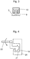
Figure 3 illustrates a preferred embodiment of a guide means for guiding the door leaf into a closed position as viewed in horizontal direction. -
Figure 4 illustrates a preferred embodiment of a positioning means for positioning the door leaf relative to a doorway. -
Figures 1 and illustrates a preferred embodiment of adoor leaf 1 for covering adoorway 2 according to an embodiment. The door leaf comprises afirst door panel 3 and asecond door panel 4, which first andsecond door panel door leaf 1 comprises one ormore springs 5, in the illustrated embodiment at least two ofsuch springs 5, loadable to push thedoor panels door leaf 1 in in a closed position as illustrated inFigure 2 . - When the
door leaf 1 is in closed position, thesecond door panel 4 leans on aborder 8 of thedoorway 2 at least in said thickness direction, and thedoor panels more springs 5 are in loaded state where they push thesecond door panel 4 to move in said thickness direction t towards the border of thedoorway 2, whereby thesecond door panel 4 is pressed against the border of thedoorway 2, directly or via one ormore seals seals - When the
door leaf 1 is in closed position, thefirst panel 3 is positioned such that it provides the one ormore springs 5 the reaction force needed by the one ormore springs 5 for pushing thesecond door panel 4 to move in said thickness direction t towards the border of thedoorway 2. - In the preferred embodiment illustrated, each said
door panel first skin 3a;4a made of sheet metal and asecond skin 3b;4b made of sheet metal, and aspace 18 between said first andsecond skin door leaf 1 is made simple and cheap, and panel elements used in regular doors can be used also in this special door and need for tailor-made components is reduced. This construction also makes it possible to make thedoor leaf 1 simply fireproof. Thedoor leaf 1 is moreover preferably such that thefirst panel 3 and/or thesecond panel 4 comprises aspace 16 contain afireproof filling 17, such as a filling comprising fire proof polyurethane material, such as polyurethane material comprising a fire retardant additive. The polyurethane is preferably polyurethane foam. The fireproof filling 16 preferably fills substantially thespace 16. - As mentioned the first and the
second door panel - In the preferred embodiment illustrated, the one or
more springs 5 are loadable by moving thedoor panels more springs 5 are arranged to elastically deform when thedoor panels - In the preferred embodiment illustrated, the one or
more springs 5 are between the first andsecond door panel - The one or
more springs 5 illustrated are coil springs, but it is possible to modify the construction such that instead of coil springs the one or more springs are some other kind of springs, such as disc springs, leaf springs, torsion springs or gas springs, for example. In the preferred embodiment illustrated, the one ormore springs 5 are loadable by compression in said thickness direction. - The
door leaf 1 preferably comprises aseal 6a provided on thesecond door panel 4 for being pressed against aborder 8 of adoorway 2 for sealing the gap 7 between thesecond door panel 4 and aborder 8 of adoorway 2. Theseal 6a is in the preferred embodiment provided on an outer surface of thesecond door panel 4, the surface facing in said thickness direction t away from thesecond door panel 4. Such aseal 6b can alternatively, or additionally be provided on the border of theopening 2, as disclosed inFigure 2 . Thus, when thedoor leaf 1 is in closed position, thesecond door panel 4 can lean, pushed by the one ormore springs 5, on aborder 8 of thedoorway 2 at least in said thickness direction via one ormore seals - The seal(s) 6a,6b facilitate airtight closing of the
door leaf 1. This is advantageous when thedoor leaf 1 covers adoorway 2 of a room for medical treatment and/or examination. Airtight closing is advantageous as it prevents air flow into the room, which air flow could bring harmful gases or impurities into the room. The seal(s) 6a,6b is/are also advantageous when thedoor leaf 1 is a fire door leaf, since then the flames and/or possible gases produced in fire cannot move between rooms separated by thedoor leaf 1. Each saidseal seal door leaf 1 into closed position can effectively seal the aforementioned gap. - In the preferred embodiment, the door leaf comprises a
space 18 between thefirst panel 3 and thesecond panel 4 into which the first panel can at least partially move when the first andsecond door panel door leaf 1 is a fire door leaf, since it provides a further isolation for heat transmission through thedoor leaf 1. This facilitates keeping the surface temperature of the outer face of the door panel facing away from the room in fire from rising high. Thespace 18 is also advantageous as it allows use of screws or rivets in manufacturing of thepanels space 18 and hidden between thepanels space 18 is also advantageous as it can be used for receiving and hiding also other components, such as the positioningmember 19 and/or components for operating it. Thespace 18 can be closed in horizontal direction with acover plate 11 forming a side plate of thedoor leaf 1. The cover plate then preferably is mounted on one of thepanels panels panels space 18 can be closed in horizontal direction with an elastic cover sheet forming a side sheet of thedoor leaf 1, which elastic cover can deform such that it allows movement of thepanels - The
door leaf 1 can be a door leaf for covering adoorway 2 of a room for medical treatment and/or examination. Then, thedoor leaf 1, preferably thefirst panel 3 and/or thesecond panel 4 thereof, comprises at least onelead member 15, such as a lead plate for absorbing radiation, particularly X-ray radiation. Due to the above described suitability for serving as a fireproof door leaf, thedoor leaf 1 can be a fireproof door leaf for covering adoorway 2 of a room for medical treatment and/or examination. - In the preferred embodiment illustrated, the
door leaf 1 comprises one ormore guide members 9 for guiding the door leaf into a closed position. Thedoor leaf 1 is preferably a sliding door leaf. In this case, saidguide members 9 areguide runners 9 comprised in thedoor leaf 1 suitable for being guided by aguide rail 10 mounted in proximity of thedoorway 2, the guide runners being for example rollers or sliders. This could alternatively be vice versa, such that said one ormore guide members 9 comprised in the door comprise a guide rail suitable for receiving and for being guided by a guide runner, such as a roller or slider that is mounted in proximity of thedoorway 2, preferably stationary. Thedoor leaf 1 is preferably a sliding door leaf, but it could alternatively be hinged door leaf. - The structure of the
door leaf 1 is preferably moreover such that the door comprises guide means 11-14 for guiding of the movement of the first andsecond door panel second door panel guide member 13, such a slider, e.g. a pin, coupled with the first panel, and aguide rail 14 coupled with thesecond panel 4 and being elongated in said thickness direction t and suitable for guiding movement of theguide member 13, or vice versa. - Said guide means 11-14 for guiding of the movement of the first and
second door panel door panel - The first and
second door panel second door panel - The
door leaf 1 preferably moreover comprises a positioningmember 19 provided on thefirst door panel 3, which positioningmember 19 is engageable with a counterpart provided on the border of the doorway for positioning thefirst door panel 3 to a position immovably relative to theborder 8 of thedoorway 2 at least in said thickness direction t when thedoor leaf 1 is in closed position. Said positioningmember 19 in the illustrated embodiment operable to move back and forth for engaging and disengaging with said counterpart. The counterpart is preferably acounterpart opening 20 provided on the border of the doorway, and the positioningmember 19, which can be a bolt such as a latch bolt or dead bolt provided on thefirst panel 3. Thedoor leaf 1 preferably comprises ahandle 22 operably connected with the positioningmember 19 as illustrated, whereby by actuation of thehandle 22 the positioningmember 19 can be operated. -
Figure 2 illustrates an arrangement implementing thedoor leaf 1 ofFigure 1 . In the arrangement, thedoor leaf 1 is movable between open position and a closed position.Figure 2 illustrates thedoor leaf 1 in closed position. In the closed position the door leaf covers thedoorway 2. Thedoor leaf 1 is a sliding door leaf. For this purpose it is and mounted to be slidable horizontally, and in particular along a horizontal plane. - The door arrangement comprises guide means 9,10 for guiding the
door leaf 1 into the closed position. Said guide means 9,10 comprise one ormore guide runners 9 comprised in thedoor leaf 1, and one ormore guide rails 10 mounted in proximity of thedoorway 2, or vice versa. Thus, the desired path and position of the components of thedoor leaf 1 during closing and opening can be achieved by aid of guide rails 10. - Said
guide rails 10 are shaped to guide thedoor leaf 1 to move at least in said thickness direction towards thedoorway 2. Saidguide rails 10 are curved to guide thedoor leaf 1 to move along a non-linear path, including a first section S1 for guiding the door leaf to move towards thedoorway 2 in horizontal direction orthogonal to said thickness direction t, and a second section S2 for guiding the door leaf to move at least in said thickness direction t towards thedoorway 2 to lean on the border of thedoorway 2. - The
door leaf 1 may be manually movable into the closed position, or the door arrangement comprises motor-driven machinery for moving thedoor leaf 1 into the closed position. - When the
door leaf 1 is in its closed position, the one ormore springs 5 are loaded to push thedoor panels second door panel 4 is pressed against the border of thedoorway 2, directly or via one ormore seals - Particularly, when the
door leaf 1 is in its closed position, thesecond door panel 4 is positioned to lean on aborder 8 of thedoorway 2 at least in said thickness direction directly or via one ormore seals door panels more springs 5 are in loaded state where they push thesecond door panel 4 to move in said thickness direction t towards the border of thedoorway 2, whereby thesecond door panel 4 is pressed against the border of thedoorway 2, directly or via one or more seals 6 provided therebetween. - In closing of the
door leaf 1, thedoor leaf 1 is arranged to move at least in said thickness direction to lean on the border of theopening 2, directly or via one or more seals 6 provided therebetween, whichborder 8 of theopening 2 is arranged to block movement of thesecond panel 4 in said thickness direction t. Further movement of thedoor leaf 1 in said thickness direction t is arranged to force thedoor panels springs 5 are loaded to push thesecond door panel 4 to move in said thickness direction t towards the border of thedoorway 2, whereby thesecond door panel 4 is pressed against theborder 8 of thedoorway 2 directly or via one or more seals 6 provided therebetween. Most preferably, when thedoor leaf 1 is in its closed position, thesecond door panel 4 is positioned to lean on aborder 8 of thedoorway 2 via one ormore seals more seals door leaf 1. This is advantageous when thedoor leaf 1 covers adoorway 2 of a room for medical treatment and/or examination. Airtight closing is advantageous as it prevents air flow into the room, which air flow could bring harmful gases or impurities into the room. The seal(s) 6a,6b is/are also advantageous when thedoor leaf 1 is a fire door leaf, since then the flames and/or possible gases produced in fire cannot move between rooms separated by thedoor leaf 1. - In the application definition that the
second door panel 4 leans on aborder 8 of the doorway at least in said thickness direction means that the leaning need not be completely in direction of the thickness direction t, but there could be, although this is not necessary, in addition to a force component extending in said thickness direction also a force component orthogonal to the thickness direction t. - The one or
more springs 5 can be preloaded to push thedoor panels door panels more springs 5 push thedoor panels more springs 5 can be loadable, i.e. further loadable, by moving thedoor panels door panels - Although the new door leaf presented is suitable for covering doorways of a room for medical treatment or examination, it is also suitable for covering other doorways, such as doorway of an elevator car or a doorway of an elevator landing leading to elevator shaft or any doorway of a building, for instance.
- It is to be understood that the above description and the accompanying Figures are only intended to teach the best way known to the inventors to make and use the invention. It will be apparent to a person skilled in the art that the inventive concept can be implemented in various ways. The above-described embodiments of the invention may thus be modified or varied, without departing from the invention, as appreciated by those skilled in the art in light of the above teachings. It is therefore to be understood that the invention and its embodiments are not limited to the examples described above but may vary within the scope of the claims.
Claims (15)
- A door leaf (1) for covering a doorway (2) comprising aa first door panel (3);a second door panel (4);wherein the first and second door panel (3,4) are parallel to each other and superimposed in their thickness direction (t) and connected to each other movably in said thickness direction (t) towards each other and away from each other; andwherein the door leaf (1) comprises one or more springs (5) loadable to push the door panels (3,4) to move in said thickness direction (t) away from each other.
- A door leaf according to claim 1, wherein the one or more springs (5) are loadable by moving the door panels (3,4) towards each other.
- A door leaf according to any of the preceding claims, wherein each said door panel (3,4) comprises a first skin (3a;4a) made of sheet metal and a second skin (3b;4b) made of sheet metal, and a space (18) between said first and second skin (3a,3b;4a,4b).
- A door leaf according to any of the preceding claims, wherein the door (1) comprises a seal (6) provided on the second door panel (4) for being pressed against a border (8) of a doorway (2) for sealing the gap (7) between the second door panel (4) and a border (8) of a doorway (2).
- A door leaf according to any of the preceding claims, wherein the one or more springs (5) are arranged to elastically deform when the door panels (3,4) move towards each other.
- A door leaf according to any of the preceding claims, wherein the one or more springs (5) are between the first and second door panel (3,4).
- A door leaf according to any of the preceding claims, wherein the door leaf (1) comprises a space (18) between the first panel (3) and the second panel (4) into which space (18) the first panel (3) can at least partially move when the first and second door panel (3,4) are moved in said thickness direction (t) towards each other.
- A door leaf according to any of the preceding claims, wherein the door leaf (1), preferably the first panel (3) and/or the second panel (4) thereof, comprises at least one lead member (15) for absorbing radiation, particularly X-ray radiation.
- A door leaf according to any of the preceding claims, wherein the door leaf (1) comprises one or more guide members (9) for guiding the door leaf (1) into a closed position, preferably by sliding, said guide members (9) preferably being guide runners (9) comprised in the door leaf (1) and suitable for being guided by a guide rail (10) mounted in proximity of the doorway (2).
- A door arrangement comprising
a doorway (2); and
a door leaf (1) for covering the doorway (2), wherein the door leaf (1) is according to any of the preceding claims. - A door arrangement according to claim 10, wherein the door leaf (1) is movable between open position and a closed position, wherein in the closed position the door leaf (1) covers the doorway (2).
- A door arrangement according to any of the preceding claims 10-11, wherein the door arrangement comprises guide means (9,10) for guiding the door leaf (1) into a closed position.
- A door arrangement according to claim 12, wherein said guide means (9,10) comprise one or more guide runners (9) comprised in the door leaf (1), and one or more guide rails (10) mounted in proximity of the doorway (2), or vice versa.
- A door arrangement according to claim 13, wherein said guide rails (10) are shaped to guide the door leaf (1) to move at least in said thickness direction (t) towards the doorway (2), said guide rails (10) preferably being curved to guide the door leaf (1) to move along a non-linear path, preferably including a first section (S1) for guiding the door leaf (1) to move in horizontal direction orthogonal to said thickness direction (t) towards the doorway (2), and a second section (S2) for guiding the door leaf (1) to move at least in said thickness direction (t) towards the doorway (1) to lean on the border of the opening (2).
- A door arrangement according to any of the preceding claims 10-14, wherein in the closed position of the door leaf (1) the second door panel (4) is positioned to lean on a border (8) of the doorway (2) at least in said thickness direction (t), and the door panels (3,4) are positioned relative to each other such that the one or more springs (5) are in loaded state where they push the second door panel (4) to move in said thickness direction (t) towards the border of the doorway (2), whereby the second door panel (4) is pressed against the border of the doorway (2), preferably either directly or via one or more seals (6a,6b) provided therebetween.
Priority Applications (1)
| Application Number | Priority Date | Filing Date | Title |
|---|---|---|---|
| EP17204377.0A EP3492683A1 (en) | 2017-11-29 | 2017-11-29 | Door and door arrangement |
Applications Claiming Priority (1)
| Application Number | Priority Date | Filing Date | Title |
|---|---|---|---|
| EP17204377.0A EP3492683A1 (en) | 2017-11-29 | 2017-11-29 | Door and door arrangement |
Publications (1)
| Publication Number | Publication Date |
|---|---|
| EP3492683A1 true EP3492683A1 (en) | 2019-06-05 |
Family
ID=60515198
Family Applications (1)
| Application Number | Title | Priority Date | Filing Date |
|---|---|---|---|
| EP17204377.0A Withdrawn EP3492683A1 (en) | 2017-11-29 | 2017-11-29 | Door and door arrangement |
Country Status (1)
| Country | Link |
|---|---|
| EP (1) | EP3492683A1 (en) |
Cited By (1)
| Publication number | Priority date | Publication date | Assignee | Title |
|---|---|---|---|---|
| CN110388172A (en) * | 2019-06-13 | 2019-10-29 | 宿州市金长城科技门业有限公司 | A kind of high-strength multifunctional security door |
Citations (4)
| Publication number | Priority date | Publication date | Assignee | Title |
|---|---|---|---|---|
| US3531577A (en) * | 1968-07-10 | 1970-09-29 | Sprague Electric Co | Door for a shielded enclosure |
| EP0541893A1 (en) * | 1991-11-14 | 1993-05-19 | Biomagnetic Technologies, Inc. | Magnetically shielded room with sliding door |
| JP2005048363A (en) * | 2003-07-29 | 2005-02-24 | Panahome Corp | Sliding door device |
| EP2878755A1 (en) * | 2013-11-29 | 2015-06-03 | ETS Lingren, Inc | Manual-automatic rf sealing system |
-
2017
- 2017-11-29 EP EP17204377.0A patent/EP3492683A1/en not_active Withdrawn
Patent Citations (4)
| Publication number | Priority date | Publication date | Assignee | Title |
|---|---|---|---|---|
| US3531577A (en) * | 1968-07-10 | 1970-09-29 | Sprague Electric Co | Door for a shielded enclosure |
| EP0541893A1 (en) * | 1991-11-14 | 1993-05-19 | Biomagnetic Technologies, Inc. | Magnetically shielded room with sliding door |
| JP2005048363A (en) * | 2003-07-29 | 2005-02-24 | Panahome Corp | Sliding door device |
| EP2878755A1 (en) * | 2013-11-29 | 2015-06-03 | ETS Lingren, Inc | Manual-automatic rf sealing system |
Cited By (1)
| Publication number | Priority date | Publication date | Assignee | Title |
|---|---|---|---|---|
| CN110388172A (en) * | 2019-06-13 | 2019-10-29 | 宿州市金长城科技门业有限公司 | A kind of high-strength multifunctional security door |
Similar Documents
| Publication | Publication Date | Title |
|---|---|---|
| CN104271865B (en) | Lifting door assembly and its lintel sealing device | |
| US20090038228A1 (en) | Method and apparatus for window closing in the sliding window system | |
| TWI258455B (en) | Airtight device of elevator doors | |
| US11352832B2 (en) | Air tight door | |
| EP3696358B1 (en) | Automatic sliding fire door | |
| WO2012093382A1 (en) | Sliding and sealing closure system | |
| KR101310495B1 (en) | Roller for a windows and doors | |
| CN211500397U (en) | A sealed screen door | |
| BRPI0700831A (en) | frame and profile system for hermetic and acoustic sealing on sliding windows and doors | |
| KR20210052826A (en) | Closed structure of automatic door | |
| US20210010323A1 (en) | Insulated door | |
| WO2014030217A1 (en) | Elevator device | |
| JP7420867B2 (en) | fittings | |
| JP6453624B2 (en) | Shutter guide rail structure | |
| KR102698392B1 (en) | Window opening/closing assist device for a window system | |
| KR20210023039A (en) | A sliding window | |
| US11959302B2 (en) | Door handle system for pivoting a sliding door | |
| JP2018204255A (en) | Sliding door device | |
| CN105612301A (en) | Fitting of an at least liftable, but preferably also displaceable wing of windows or doors | |
| WO2020021441A1 (en) | Sliding window structure | |
| KR101726856B1 (en) | Fire door | |
| KR20230144733A (en) | Sliding window system with latches | |
| KR101371335B1 (en) | Apparatus for window closing in the sliding window system | |
| JP2009179431A (en) | Elevator safety equipment | |
| CN223724437U (en) | Sliding door |
Legal Events
| Date | Code | Title | Description |
|---|---|---|---|
| PUAI | Public reference made under article 153(3) epc to a published international application that has entered the european phase |
Free format text: ORIGINAL CODE: 0009012 |
|
| AK | Designated contracting states |
Kind code of ref document: A1 Designated state(s): AL AT BE BG CH CY CZ DE DK EE ES FI FR GB GR HR HU IE IS IT LI LT LU LV MC MK MT NL NO PL PT RO RS SE SI SK SM TR |
|
| AX | Request for extension of the european patent |
Extension state: BA ME |
|
| STAA | Information on the status of an ep patent application or granted ep patent |
Free format text: STATUS: THE APPLICATION IS DEEMED TO BE WITHDRAWN |
|
| 18D | Application deemed to be withdrawn |
Effective date: 20191206 |