EP3492681A1 - Vacuum glazing and method for manufacturing the same - Google Patents
Vacuum glazing and method for manufacturing the same Download PDFInfo
- Publication number
- EP3492681A1 EP3492681A1 EP18208525.8A EP18208525A EP3492681A1 EP 3492681 A1 EP3492681 A1 EP 3492681A1 EP 18208525 A EP18208525 A EP 18208525A EP 3492681 A1 EP3492681 A1 EP 3492681A1
- Authority
- EP
- European Patent Office
- Prior art keywords
- glazing
- frame
- glazings
- vacuum
- coupled
- Prior art date
- Legal status (The legal status is an assumption and is not a legal conclusion. Google has not performed a legal analysis and makes no representation as to the accuracy of the status listed.)
- Granted
Links
Images











Classifications
-
- E—FIXED CONSTRUCTIONS
- E06—DOORS, WINDOWS, SHUTTERS, OR ROLLER BLINDS IN GENERAL; LADDERS
- E06B—FIXED OR MOVABLE CLOSURES FOR OPENINGS IN BUILDINGS, VEHICLES, FENCES OR LIKE ENCLOSURES IN GENERAL, e.g. DOORS, WINDOWS, BLINDS, GATES
- E06B3/00—Window sashes, door leaves, or like elements for closing wall or like openings; Layout of fixed or moving closures, e.g. windows in wall or like openings; Features of rigidly-mounted outer frames relating to the mounting of wing frames
- E06B3/66—Units comprising two or more parallel glass or like panes permanently secured together
- E06B3/673—Assembling the units
- E06B3/67304—Preparing rigid spacer members before assembly
- E06B3/67321—Covering spacer elements, e.g. with sealants
-
- C—CHEMISTRY; METALLURGY
- C03—GLASS; MINERAL OR SLAG WOOL
- C03C—CHEMICAL COMPOSITION OF GLASSES, GLAZES OR VITREOUS ENAMELS; SURFACE TREATMENT OF GLASS; SURFACE TREATMENT OF FIBRES OR FILAMENTS MADE FROM GLASS, MINERALS OR SLAGS; JOINING GLASS TO GLASS OR OTHER MATERIALS
- C03C27/00—Joining pieces of glass to pieces of other inorganic material; Joining glass to glass other than by fusing
- C03C27/06—Joining glass to glass by processes other than fusing
- C03C27/10—Joining glass to glass by processes other than fusing with the aid of adhesive specially adapted for that purpose
-
- E—FIXED CONSTRUCTIONS
- E06—DOORS, WINDOWS, SHUTTERS, OR ROLLER BLINDS IN GENERAL; LADDERS
- E06B—FIXED OR MOVABLE CLOSURES FOR OPENINGS IN BUILDINGS, VEHICLES, FENCES OR LIKE ENCLOSURES IN GENERAL, e.g. DOORS, WINDOWS, BLINDS, GATES
- E06B3/00—Window sashes, door leaves, or like elements for closing wall or like openings; Layout of fixed or moving closures, e.g. windows in wall or like openings; Features of rigidly-mounted outer frames relating to the mounting of wing frames
- E06B3/54—Fixing of glass panes or like plates
- E06B3/5454—Fixing of glass panes or like plates inside U-shaped section members
-
- E—FIXED CONSTRUCTIONS
- E06—DOORS, WINDOWS, SHUTTERS, OR ROLLER BLINDS IN GENERAL; LADDERS
- E06B—FIXED OR MOVABLE CLOSURES FOR OPENINGS IN BUILDINGS, VEHICLES, FENCES OR LIKE ENCLOSURES IN GENERAL, e.g. DOORS, WINDOWS, BLINDS, GATES
- E06B3/00—Window sashes, door leaves, or like elements for closing wall or like openings; Layout of fixed or moving closures, e.g. windows in wall or like openings; Features of rigidly-mounted outer frames relating to the mounting of wing frames
- E06B3/04—Wing frames not characterised by the manner of movement
- E06B3/06—Single frames
- E06B3/08—Constructions depending on the use of specified materials
- E06B3/12—Constructions depending on the use of specified materials of metal
-
- E—FIXED CONSTRUCTIONS
- E06—DOORS, WINDOWS, SHUTTERS, OR ROLLER BLINDS IN GENERAL; LADDERS
- E06B—FIXED OR MOVABLE CLOSURES FOR OPENINGS IN BUILDINGS, VEHICLES, FENCES OR LIKE ENCLOSURES IN GENERAL, e.g. DOORS, WINDOWS, BLINDS, GATES
- E06B3/00—Window sashes, door leaves, or like elements for closing wall or like openings; Layout of fixed or moving closures, e.g. windows in wall or like openings; Features of rigidly-mounted outer frames relating to the mounting of wing frames
- E06B3/66—Units comprising two or more parallel glass or like panes permanently secured together
- E06B3/6612—Evacuated glazing units
-
- E—FIXED CONSTRUCTIONS
- E06—DOORS, WINDOWS, SHUTTERS, OR ROLLER BLINDS IN GENERAL; LADDERS
- E06B—FIXED OR MOVABLE CLOSURES FOR OPENINGS IN BUILDINGS, VEHICLES, FENCES OR LIKE ENCLOSURES IN GENERAL, e.g. DOORS, WINDOWS, BLINDS, GATES
- E06B3/00—Window sashes, door leaves, or like elements for closing wall or like openings; Layout of fixed or moving closures, e.g. windows in wall or like openings; Features of rigidly-mounted outer frames relating to the mounting of wing frames
- E06B3/66—Units comprising two or more parallel glass or like panes permanently secured together
- E06B3/663—Elements for spacing panes
-
- E—FIXED CONSTRUCTIONS
- E06—DOORS, WINDOWS, SHUTTERS, OR ROLLER BLINDS IN GENERAL; LADDERS
- E06B—FIXED OR MOVABLE CLOSURES FOR OPENINGS IN BUILDINGS, VEHICLES, FENCES OR LIKE ENCLOSURES IN GENERAL, e.g. DOORS, WINDOWS, BLINDS, GATES
- E06B3/00—Window sashes, door leaves, or like elements for closing wall or like openings; Layout of fixed or moving closures, e.g. windows in wall or like openings; Features of rigidly-mounted outer frames relating to the mounting of wing frames
- E06B3/66—Units comprising two or more parallel glass or like panes permanently secured together
- E06B3/663—Elements for spacing panes
- E06B3/66309—Section members positioned at the edges of the glazing unit
- E06B3/66342—Section members positioned at the edges of the glazing unit characterised by their sealed connection to the panes
-
- E—FIXED CONSTRUCTIONS
- E06—DOORS, WINDOWS, SHUTTERS, OR ROLLER BLINDS IN GENERAL; LADDERS
- E06B—FIXED OR MOVABLE CLOSURES FOR OPENINGS IN BUILDINGS, VEHICLES, FENCES OR LIKE ENCLOSURES IN GENERAL, e.g. DOORS, WINDOWS, BLINDS, GATES
- E06B3/00—Window sashes, door leaves, or like elements for closing wall or like openings; Layout of fixed or moving closures, e.g. windows in wall or like openings; Features of rigidly-mounted outer frames relating to the mounting of wing frames
- E06B3/66—Units comprising two or more parallel glass or like panes permanently secured together
- E06B3/673—Assembling the units
-
- E—FIXED CONSTRUCTIONS
- E06—DOORS, WINDOWS, SHUTTERS, OR ROLLER BLINDS IN GENERAL; LADDERS
- E06B—FIXED OR MOVABLE CLOSURES FOR OPENINGS IN BUILDINGS, VEHICLES, FENCES OR LIKE ENCLOSURES IN GENERAL, e.g. DOORS, WINDOWS, BLINDS, GATES
- E06B3/00—Window sashes, door leaves, or like elements for closing wall or like openings; Layout of fixed or moving closures, e.g. windows in wall or like openings; Features of rigidly-mounted outer frames relating to the mounting of wing frames
- E06B3/66—Units comprising two or more parallel glass or like panes permanently secured together
- E06B3/673—Assembling the units
- E06B3/67326—Assembling spacer elements with the panes
-
- E—FIXED CONSTRUCTIONS
- E06—DOORS, WINDOWS, SHUTTERS, OR ROLLER BLINDS IN GENERAL; LADDERS
- E06B—FIXED OR MOVABLE CLOSURES FOR OPENINGS IN BUILDINGS, VEHICLES, FENCES OR LIKE ENCLOSURES IN GENERAL, e.g. DOORS, WINDOWS, BLINDS, GATES
- E06B3/00—Window sashes, door leaves, or like elements for closing wall or like openings; Layout of fixed or moving closures, e.g. windows in wall or like openings; Features of rigidly-mounted outer frames relating to the mounting of wing frames
- E06B3/66—Units comprising two or more parallel glass or like panes permanently secured together
- E06B3/677—Evacuating or filling the gap between the panes ; Equilibration of inside and outside pressure; Preventing condensation in the gap between the panes; Cleaning the gap between the panes
- E06B3/6775—Evacuating or filling the gap during assembly
-
- Y—GENERAL TAGGING OF NEW TECHNOLOGICAL DEVELOPMENTS; GENERAL TAGGING OF CROSS-SECTIONAL TECHNOLOGIES SPANNING OVER SEVERAL SECTIONS OF THE IPC; TECHNICAL SUBJECTS COVERED BY FORMER USPC CROSS-REFERENCE ART COLLECTIONS [XRACs] AND DIGESTS
- Y02—TECHNOLOGIES OR APPLICATIONS FOR MITIGATION OR ADAPTATION AGAINST CLIMATE CHANGE
- Y02A—TECHNOLOGIES FOR ADAPTATION TO CLIMATE CHANGE
- Y02A30/00—Adapting or protecting infrastructure or their operation
- Y02A30/24—Structural elements or technologies for improving thermal insulation
- Y02A30/249—Glazing, e.g. vacuum glazing
-
- Y—GENERAL TAGGING OF NEW TECHNOLOGICAL DEVELOPMENTS; GENERAL TAGGING OF CROSS-SECTIONAL TECHNOLOGIES SPANNING OVER SEVERAL SECTIONS OF THE IPC; TECHNICAL SUBJECTS COVERED BY FORMER USPC CROSS-REFERENCE ART COLLECTIONS [XRACs] AND DIGESTS
- Y02—TECHNOLOGIES OR APPLICATIONS FOR MITIGATION OR ADAPTATION AGAINST CLIMATE CHANGE
- Y02B—CLIMATE CHANGE MITIGATION TECHNOLOGIES RELATED TO BUILDINGS, e.g. HOUSING, HOUSE APPLIANCES OR RELATED END-USER APPLICATIONS
- Y02B80/00—Architectural or constructional elements improving the thermal performance of buildings
- Y02B80/22—Glazing, e.g. vaccum glazing
Definitions
- the vacuum glazing may be formed by making, in the vacuum state, the space between the two glazings.
- the vacuum glazing is more advantages than the double glazing in terms of capability to block heat from being transferred to an inside or an outside of glass.
- the frame includes a plurality of parts which are bent or curved. Accordingly, the close contact property between two glazings may be improved.
- the four frame parts include a first frame part coupled to first edge portions of the first and second plate glazings 110 and 120, a second frame part coupled to second edge portions of the first and second plate glazings 110 and 120, a third frame part coupled to third edge portions of the first and second plate glazings 110 and 120, and a fourth frame part coupled to fourth edge portions of the first and second plate glazings 110 and 120
- the exhaust finishing member 140 blocks the exhaust hole 125.
- the exhaust finishing member 140 may include glass frit having a lower melting point.
- the sealant 170 may be provided in the state that the sealant 170 has already been attached to the frame 150 before the frame 150 is assembled with the first and second glazings 110, 120.
- the sealant 170 may be coated on the frame 150 and may include glass frit.
- the sealant 170 is melted and compressed between the frame 150 and the first and second glazings 110 and 120.
- the effect of sealing the coupling part of the frame 150 may be increased.
- the third part 153 is connected with the first and second parts 151 and 152 and may be positioned at the side portions of the first and second glazings 110 and 120.
- the third part 153 may have a bent or rounded shape.
- the third part 153 may have a hemispheric shape.
- the frame 150 may apply elasticity force to the first and second glazings 110 and 120 due to the shape of the third part 153, such that the first and second glazings 110 and 120 may make close contact with the upper and lower portion of the frame 150.
- the spacer 130 may be provided on the top surface of the first glazing 110.
- the spacer 130 may include a plurality of spacers and the plurality of spacers may be provided at preset distances.
- the plurality of spacers 130 may be arranged in the form of a lattice (matrix).
- the plurality of spacers 130 may protrude from the top surface of the first glazing 110 (see FIG. 5B ).
- the exhaust tube 128 is coupled to the exhaust hole 125, and vacuum-pumping is performed through the exhaust tube 128.
- the vacuum layer 180 and the frame vacuum layer 182 may be formed (see FIG. 5E ).
- the exhaust hole 125 may be clogged by the exhaust finishing member 140, and an exhaust cap 145 may be coupled to an outer portion of the exhaust finishing member 140 (see FIG. 5F ).
- the vacuum-pumping process and the process of coupling the exhaust finishing member 140 to the exhaust cap 145 may be performed in a vacuum chamber having a vacuum atmosphere. Through the manufacturing method, the vacuum glazing 10 may be easily manufactured.
- the first and second glazings 110 and 120 are spaced apart from each other in a vertical direction, and a vacuum layer 180a may be formed in a space between the first and second glazings 110 and 120.
- the plurality of glazings 110 and 120 include a first glazing 110 and a second glazing 120.
- the description of the first and second glazings 110 and 120 will be understood by referring to those of the first embodiment.
- the plurality of frame parts 151b, 152b, 153b, and 154b may be linked to each other.
- one side portion of the first frame part 151b may be separated from one side portion of the fourth frame part 151d.
- the frame 150b may have the shape bent several times.
- the first frame part 151b may be assembled with the fourth frame part 151d after the frame 150b is assembled with the first and second glazings 110 and 120.
- the frame 150a may be coupled to edges of the first and second glazings 110 and 120 such that the vacuum layer 180 may be maintained in a vacuum state.
- the frame 150a may constitute the edge portion of the vacuum layer 180a.
- the sealant 170b may be interposed between the inner circumferential surfaces of the parts 151b, 152b, 153b, and 154b of the frame 150 and the first lateral side surface 113 of the first glazing 110.
- the sealant 170b may be interposed between the inner circumferential surfaces of the parts 151b, 152b, 153b, and 154b of the frame 150 and the second lateral side surface 123 of the second glazing 120.
- a spacer 130 may be interposed between the first and second glazings 110 and 120 to support the first and second glazings 110 and 120.
- the spacer 130 may be interposed in the vacuum layer 180c. The details of the spacer 130 may be understood by referring to the description of the first embodiment.
- the width 'w' of the frame 150c is formed to be 3 mm or less, the sealant 170c is not compressed in the space between the frame 150c and the first and second glazings 110 and 120 by the sufficient length. Accordingly, the sealing effect may be degraded. In contrast, if the width 'w3' of the frame 150c is formed to be 10 mm or more, since heat may be excessively lost in the edges of the first and second glazings 110 and 120, the insulation performance may be degraded.
- the second glazing 120 may be covered on the frame 150c (see FIG. 17B ). After the frame 150c is interposed between the first and second glazings 110 and 120, the assembly between the first and second glazings 110 and 120 and the frame 150c is heated. In this heating procedure, the sealant 170c is melted and compressed to seal the space between the first and second glazings 110 and 120 and the frame 150c (see FIG. 17B ).
- the insulating performance may be varied depending on the thickness of the frame according to the embodiment of the present invention.
- the thicknesses of the frames 150, 150a, and 150b described in the first to third embodiments are in the range of 0.2-1.0 mm.
- reference sign A on a horizontal axis represents that only the sealant is provided instead of the frame between the first and second glazings.
- a vertical axis represents an insulating load, that is, a heat transfer load value. Those skilled in the art may understand that an amount of transferred heat is increased if the insulating load is increased.
- reference signs B1 to B3 represent a less insulating load than reference sign A.
- the insulting performance of the vacuum glazing may be improved.
Landscapes
- Engineering & Computer Science (AREA)
- Civil Engineering (AREA)
- Structural Engineering (AREA)
- Chemical & Material Sciences (AREA)
- Ceramic Engineering (AREA)
- Life Sciences & Earth Sciences (AREA)
- Chemical Kinetics & Catalysis (AREA)
- General Chemical & Material Sciences (AREA)
- Geochemistry & Mineralogy (AREA)
- Materials Engineering (AREA)
- Organic Chemistry (AREA)
- Securing Of Glass Panes Or The Like (AREA)
- Joining Of Glass To Other Materials (AREA)
Abstract
Description
- The present invention relates to a vacuum glazing and a method for manufacturing the same.
- Glass may be used for the door of a home appliance. For example, the glass may be used for the door of a refrigerator. If the glass is applied to the door of the refrigerator, a user has an advantage in that the user may easily see foods stored in the refrigerator through transparent glass without opening the door.
- However, since the glass represents a low insulating rate due to the intrinsic characteristic of the glass, heat can be easily transferred to chilly air stored in the refrigerator from the outside through the glass. In particular, when the glass constitutes a glazing in a single layer, the low insulating rate may be a more serious problem.
- To compensate for the low insulating rate, the glass may constitute a double glazing or a vacuum glazing including at least two glazings. The double glazing may be formed by injecting specific gas, which has a low heat transfer coefficient, between the two glazings.
- In addition, the vacuum glazing may be formed by making, in the vacuum state, the space between the two glazings. The vacuum glazing is more advantages than the double glazing in terms of capability to block heat from being transferred to an inside or an outside of glass.
- Regarding the vacuum glazing, there are introduced following related arts.
- 1. Korean Unexamined Patent Publication No. (publication date):
10-2009-0036709 (April 15, 2009 - The related art has the following problems.
- First, as high thickness of an adhesive (glass frit) for bonding the two glazings to each other is formed (to about 8 mm or more) to improve the adhesive force between two glazings, heat is transferred through the bonding part, thereby forming dew. In addition, an additional heater is required to prevent the dew from being produced.
- Second, as a thick vacuum layer is formed due to the thick adhesive, the height of a spacer to support the two glazings between the two glazings is increased. Accordingly, the spacer may fall down or may not be stably installed in the manufacturing process of the vacuum glazing.
- In addition, when the diameter of the spacer is increased to resolve the above problem, the insulating performance of the vacuum glazing may be deteriorated.
- The present invention provides a vacuum glazing and a method for manufacturing the same, capable of improving insulating performance. In particular, the present invention provides a vacuum glazing capable of improving thermal insulating performance in an edge portion of a glazing.
- In addition, the present invention provides a vacuum glazing and a method for manufacturing the same, capable of improving the bonding property and strength of a glazing by applying a metallic frame to a part (the bonding part) at which two glazings are bonded to each other.
- Further, the present invention provides a vacuum glazing and a method for manufacturing the same, capable of lowering heat transfer at the bonding part by using a metallic frame having a lower heat transfer coefficient. In addition, the present invention provides a vacuum glazing, capable of reducing a heat transfer coefficient by applying an optimal shape of the frame and thus increasing the length of a heat transfer path.
- Further, the present invention provides a vacuum glazing in which a metallic frame having a low corrosion property is used. Thus, even if dew is produced at the bonding part, the metallic frame can be prevented from being corroded.
- The present invention provides a vacuum glazing simply manufactured by assembling a glazing with a frame having an adhesive. Further, the present invention provides a vacuum glazing and a method for manufacturing the same, in which a frame having an adhesive integrated thereto is applied as separate component.
- According to an aspect of the present invention, a vacuum glazing may include a vacuum layer formed between a first glazing and a second glazing, a spacer provided in the vacuum layer, a frame provided at edge portions of the first and second glazings, and a sealant interposed between the frame and surfaces of the first and second glazings to perform sealing of the vacuum layer. Accordingly, the insulating performance of the vacuum glazing may be improved.
- The frame may include a metallic member, especially, a stainless material. Accordingly, the strength of the vacuum glazing may be improved, and the bonding property of the glazing may be improved.
- The frame may be coupled to lateral side surfaces of the first and second glazings and may have a bent shape. Accordingly, the close contact property of the first and second glazings may be improved.
- The frame may further include a third part coupling a first part to a second part and having a bent or a rounded shape. Accordingly, the frame may apply elasticity to the first and second glazings.
- The first and second parts may be coupled to top and bottom surfaces of the first and second glazings, and the third part may be provided on lateral side surfaces of the first and second glazings. Accordingly, the bonding property between the first and second glazings may be improved.
- The vacuum layer includes a frame vacuum layer interposed between the lateral side surfaces of the first and second glazings and an inner surface of the third part.
- Since the sealant is provided between the inner circumferential surface of the frame and the outer surfaces of the first and second glazings, the sealing effect of the vacuum glazing may be improved.
- Since the sealant is provided between the frame and the top surface of the first glazing and between the frame and the bottom surface of the second glazing, the sealing effect of the vacuum glazing may be improved.
- The first and second glazings may have a rectangular shape and the frame may include four frame parts corresponding to edge portions of the first and second glazings. Accordingly, the first and second glazings may be stably coupled to the frame.
- Since the vertical width of the insulating layer is in the range of 0.18-0.22 mm, and the thickness of the frame is in the range of 0.2-1.0 mm, the insulating performance may be improved and the stiffness of the frame may be maintained.
- Since each of parts of the first and second glazings, which are coupled to the frame, has a lateral-width (w) in a range of 3-10 mm, the sealant may be stably formed.
- According to another aspect of the present invention, a method of manufacturing a vacuum glazing includes: installing a spacer on a top surface of a first glazing, covering a second glazing on the spacer, manufacturing a glazing assembly by coupling a frame including a metallic material to edge portions of the first glazing and the second glazing, sealing a space enclosed by the first glazing, the second glazing and the frame by heating the glazing assembly, forming a vacuum layer in the space by pumping air out through an exhaust hole in the second glazing, and filling the exhaust hole with an exhaust finishing material.
- As described above, according to the present invention, the frame and the adhesive may be assembled between the two glazings. Accordingly, the insulating performance of the vacuum glazing may be improved. In particular, the vacuum performance at the bonding part (the end portion) of the vacuum glazing, with which the frame is assembled, may be improved.
- In addition, the frame may include the metallic material, so the bonding property of the glazing is improved. Accordingly, the strength in the bonding part may be improved.
- In addition, the frame may include a stainless material having a lower heat transfer coefficient and a lower corrosion property. Accordingly, the vacuum glazing may be configured to represent the lower heat transfer at the bonding part and to represent a stronger property against moisture.
- In addition, the frame is configured to surround the edge portions of the two glazings, so the length of the heat transfer path is increased through the frame. Accordingly, the heat transfer coefficient may be lowered at the bonding part.
- In addition, the frame includes a plurality of parts which are bent or curved. Accordingly, the close contact property between two glazings may be improved.
- Further, since the glazing may be assembled with the frame having the adhesive integrated thereto, the manufacturing method may be simplified and the frame may be mass produced.
-
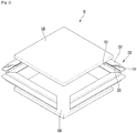
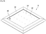
FIG. 1 is a perspective view illustrating the configuration of a vacuum glazing according to a first embodiment of the present invention; -
FIG. 2 is an exploded perspective view illustrating the configuration of the vacuum glazing according to the first embodiment of the present invention; -
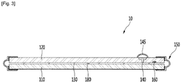
FIG. 3 is a sectional view taken along line I-I' ofFIG. 1 ; -
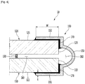
FIG. 4 is a sectional view taken along line II-II' ofFIG. 1 ; -
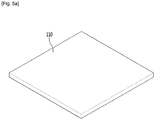
FIGS. 5A to 5F are views illustrating a method for manufacturing the vacuum glazing according to the first embodiment of the present invention; -
FIG. 6 is a perspective view illustrating the configuration of the vacuum glazing according to a second embodiment of the present invention; -
FIG. 7 is an exploded perspective view illustrating the configuration of the vacuum glazing according to the second embodiment of the present invention; -
FIG. 8 is a sectional view taken along line III-III' ofFIG. 6 ; -
FIGS. 9A to 9C are views illustrating a method for manufacturing the vacuum glazing according to the second embodiment of the present invention; -
FIG. 10 is a perspective view illustrating the configuration of the vacuum glazing according to the third embodiment of the present invention; -
FIG. 11 is an exploded perspective view illustrating the configuration of the vacuum glazing according to the third embodiment of the present invention; -
FIG. 12 is a sectional view taken along line IV-IV' ofFIG. 10 ; -
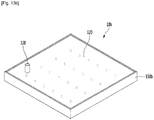
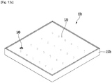
FIGS. 13A to 13C are views illustrating a method for manufacturing the vacuum glazing according to the third embodiment of the present invention; -
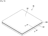
FIG. 14 is a perspective view illustrating the configuration of the vacuum glazing according to a fourth embodiment of the present invention; -
FIG. 15 is an exploded perspective view illustrating the configuration of the vacuum glazing according to the fourth embodiment of the present invention; -
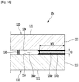
FIG. 16 is a sectional view taken along line V-V' ofFIG. 14 ; -
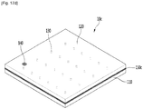
FIGS. 17A to 17D are views illustrating a method for manufacturing the vacuum glazing according to the third embodiment of the present invention; and -
FIG. 18 is an experimental graph illustrating the comparison between insulating loads measured depending on the thickness of the frame according to the present invention. - Hereinafter, the detailed embodiment of the present invention will be described. Those skilled in the art understanding the present invention may easily suggest other embodiments equivalent to the present invention.
-
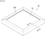
FIG. 1 is a perspective view illustrating the configuration of a vacuum glazing according to a first embodiment of the present invention,FIG. 2 is an exploded perspective view illustrating the configuration of the vacuum glazing according to the first embodiment of the present invention,FIG. 3 is a sectional view taken along line I-I' ofFIG. 1 , andFIG. 4 is a sectional view taken along line II-II' ofFIG. 1 . - Referring to
FIGS. 1 to 4 , avacuum glazing 10 according to the first embodiment of the present invention may be used for a refrigerator door. Avacuum glazing 10 according to the second to fourth embodiment to be described below may be used for the refrigerator door. - The
vacuum glazing 10 includes a plurality ofglazings frame 150 which is coupled to edge portions of the plurality ofglazings glazings glazings - The plurality of
glazings first glazing 110 and asecond glazing 120 provided at one side of thefirst glazing 110. Although the direction that the first andsecond glazings second glazing 120 may be provided above thefirst glazing 110 based on a drawing. - For example, when the
vacuum glazing 10 is used for the refrigerator door, thesecond glazing 120 may be formed on the rear surface of the refrigerator door and thefirst glazing 110 may be formed on the front surface of the refrigerator. - The
first glazing 110 and thesecond glazing 120 may be provided in the shape of a thin plate. For example, the thickness of thefirst glazing 110 orsecond glazing 120 may be formed in the range of 3.5- 4.5 mm. - In addition, the first and
second glazings second glazings - The
frame 150 may seal the edge portions of the first andsecond glazings frame 150 includes a plurality of frame parts arranged along the edge portions of the first andsecond glazings - The four frame parts include a first frame part coupled to first edge portions of the first and
second plate glazings second plate glazings second plate glazings second plate glazings - The first to fourth frame parts may have the same configuration and the same shape. The
frame 150 may have the rectangular shape having an open inner portion depending on the arrangement of the first to fourth frame parts. In addition, coupling surfaces 155 may be formed on opposite side portions of each of the first frame part to the fourth frame part. Thecoupling surface 155 may be configured to extend while being inclined with respect to four edge portions of the first andsecond glazings - The
frame 150 includes a metallic member. For example, the metallic material may include a stainless material having a lower heat transfer coefficient. The stainless material has a characteristic representing excellent adhesion to asealant 170 to be described. - As the
frame 150 is formed of metal, the bonding property between the first andsecond glazings frame 150 may be improved, and the strength may be improved between the first andsecond glazings frame 150. - The first and
second glazings vacuum layer 180 may be formed in a space between the first andsecond glazings vacuum layer 180 may be formed between the top surface of thefirst glazing 110 and the bottom surface of thesecond glazing 120. The vertical width of thevacuum layer 180 may be formed in the range of about 0.18-0.22 mm, and the vacuum pressure of thevacuum layer 180 may be 10-3 Torr or less. - A
spacer 130 may be interposed between the first andsecond glazings second glazings spacer 130 may be provided in thevacuum layer 180 and may have, for example, the substantially cylinder shape. The lower portion of thespacer 130 may be supported to the top surface of thefirst glazing 110, and the upper portion of thespacer 130 may support the bottom surface of thesecond glazing 120. - The
spacer 130 may include a plurality ofspacers 130. The diameter of thespacer 130 may be about 0.5 mm, and the distance between the plurality ofspacers 130 may be about 25 mm. - An
exhaust finishing member 140 is provided in thesecond glazing 120. Those skilled in the art understands that theexhaust finishing member 140 seals an exhaust hole 125 (seeFIG. 5C ) formed in thesecond glazing 120. - The
exhaust hole 125 may be configured to exhaust gas present between the first andsecond glazings second glazings exhaust hole 125 may be formed through thesecond glazing 120 in a vertical direction. - After the gas is exhausted through the
exhaust hole 125, theexhaust finishing member 140 blocks theexhaust hole 125. For example, theexhaust finishing member 140 may include glass frit having a lower melting point. - The
vacuum glazing 10 may further include anexhaust cap 145 provided at an upper portion of theexhaust finishing member 140. Theexhaust cap 145 may have a cap shape to cover theexhaust finishing member 140 and may include a metallic material. Theexhaust cap 145 may prevent the external pressure of thevacuum glass 10 to be applied to theexhaust finishing member 140, thereby preventing theexhaust finishing member 140 from deviating from theexhaust hole 125 or preventing theexhaust finishing member 140 from being broken. - The
vacuum glazing 10 further includes a gas adsorbent 160 (getter). Those skilled in the art may understand that thegas adsorbent 160 may include moisture or gas which may be generated in the procedure of manufacturing thevacuum glazing 10. In other words, even though thevacuum layer 180 is formed in thevacuum glazing 10, moisture or predetermined gas may be produced in the first andsecond glazings spacer 130. Thegas adsorbent 160 allows the moisture or gas to be adsorbed thereto, such that thevacuum layer 180 may be maintained in a vacuum state. For example, thegas adsorbent 160 may further include a non-evaporable getter activated if current flows. After thevacuum glazing 10 is manufactured, power, which is supplied from the outside of thevacuum glazing 10, may be supplied to thegas adsorbent 160 through a wire. - The
frame 150 may be coupled to the edge portions of the first andsecond glazings vacuum layer 10 may be easily maintained. In other words, theframe 150 may form an edge portion of thevacuum layer 180. - Each of the four frame parts constituting the
frame 150 includes afirst part 151, asecond part 152, and athird part 153. Thefirst part 151 and thesecond part 152 may be coupled to outer surfaces of the first andsecond glazings - In detail, the
first part 151 may have a bent shape and may be configured to be coupled between abottom surface 111 and a firstlateral side surface 113 of thefirst glazing 110. In addition, thesecond part 152 may have a bent shape and may be configured to be coupled to atop surface 121 and a secondlateral side 123 of thesecond glazing 120. - The thickness of the
frame 150, that is, the thickness (t) of the first tothird parts frame 150 is 0.2 mm or less, theframe 150 may be broken when theframe 150 is processed. In contrast, if the thickness 't' of theframe 150 is 1.0 mm or more, the heat transfer performance of theframe 150 is increased, so that the insulating performance of thevacuum glazing 10 may be lowered. - The left-right width of the
frame 150, that is, the width 'w' of thebottom surface 111 of thefirst glazing 110, which is coupled to thefirst part 151, may be formed in the range of 3-10 mm. The width 'w' may be equal to the width of thetop surface part 121 of thesecond glazing 120, which is coupled to thesecond part 152. - If the width 'w' of the
frame 150 is formed to be 3 mm or less, thesealant 170 is not compressed in the space between theframe 150 and the first andsecond glazings frame 150 is formed to be 10 mm or more, since heat may be excessively lost in the edge portions of the first andsecond glazings - A
sealant 170 may be further included in thevacuum glazing 10. Thesealant 170 may be provided in the coupling part between thefirst part 151 and thefirst glazing 110, and the coupling part between thesecond part 152 and thesecond glazing 120. - In detail, the
sealant 170 may be interposed between thefirst part 151 and thebottom surface 111 and between thefirst part 151 and the firstlateral side surface 113. In detail, thesealant 170 may be interposed between thesecond part 152 and thetop surface 121 and between thesecond part 152 and the secondlateral side portion 123. Thesealant 170 may be interposed between thethird part 153 and at least a portion of the firstlateral side surface 113 and/or the secondlateral side surface 123. - The
sealant 170 may be provided in the state that thesealant 170 has already been attached to theframe 150 before theframe 150 is assembled with the first andsecond glazings sealant 170 may be coated on theframe 150 and may include glass frit. When theframe 150 is heated after theframe 150 is coupled to the first andsecond glazings sealant 170 is melted and compressed between theframe 150 and the first andsecond glazings sealant 170, the effect of sealing the coupling part of theframe 150 may be increased. - The
third part 153 is connected with the first andsecond parts second glazings third part 153 may have a bent or rounded shape. For example, thethird part 153 may have a hemispheric shape. Theframe 150 may apply elasticity force to the first andsecond glazings third part 153, such that the first andsecond glazings frame 150. - A
frame vacuum layer 182 is formed among the first andsecond glazings third part 153. Theframe vacuum layer 182 may communicate with thevacuum layer 180, and thus the volume of a vacuum layer provided in thevacuum glazing 10 is enlarged. This enlarged vacuum space contributes to increasing the heat transfer resistance of thevacuum glazing 10. In a broad sense, those skilled art may understand that theframe vacuum layer 182 constitutes at least a portion of thevacuum layer 180. - The length of the
frame 150 may be relatively increased due to the configuration of the first tothird parts third part 153. Accordingly, the length of a heat transfer path may be increased due to theframe 150 and thus an amount of transferred heat may be reduced. -
FIGS. 5A to 5F are views illustrating a method for manufacturing the vacuum glazing according to the first embodiment of the present invention. Hereinafter, the method for manufacturing the vacuum glazing according to the first embodiment will be described with reference toFIGS. 5A to 5F . - First, the
first glazing 110 is provided. Thefirst glazing 110 may be provided after thefirst glazing 110 is cleaned (seeFIG. 5A ). - The
spacer 130 may be provided on the top surface of thefirst glazing 110. Thespacer 130 may include a plurality of spacers and the plurality of spacers may be provided at preset distances. For example, the plurality ofspacers 130 may be arranged in the form of a lattice (matrix). The plurality ofspacers 130 may protrude from the top surface of the first glazing 110 (seeFIG. 5B ). - The
second glazing 120 may be covered on thefirst glazing 110. If thesecond glazing 120 is disposed, upper portions of the plurality ofspacers 130 may support the bottom surface of thesecond glazing 120. - The
exhaust hole 125 may be formed in thesecond glazing 120 such that anexhaust tube 128 is coupled to theexhaust hole 125. As described above, those skilled in the art may understand theexhaust hole 125 as a component to form vacuum layers 180 and 182 by exhausting gas present between the first andsecond glazings gas adsorbent 160 may be provided on the bottom surface of the second glazing 120 (FIG. 5C ). - After the first and
second glazings frame 150 may be installed at edge portions of the first andsecond glazings frame 150 may have thesealant 170 coated on the inner surface of theframe 150. - In detail, four frame parts constituting the
frame 150 may be arranged at respective edge portions of the first andsecond glazings second glazings coupling surface 155 provided on opposite side portions of each frame part may be coupled to coupling surfaces of two adjacent frame parts. - After the
frame 150 is assembled with the first andsecond glazings second glazings frame 150 is heated. In this heating procedure, thesealant 170 is melted and compressed to seal the space between the first andsecond glazings FIG. 5D ). - Thereafter, the
exhaust tube 128 is coupled to theexhaust hole 125, and vacuum-pumping is performed through theexhaust tube 128. Accordingly, thevacuum layer 180 and theframe vacuum layer 182 may be formed (seeFIG. 5E ). After the vacuum layers 180 and 182 are formed, theexhaust hole 125 may be clogged by theexhaust finishing member 140, and anexhaust cap 145 may be coupled to an outer portion of the exhaust finishing member 140 (seeFIG. 5F ). The vacuum-pumping process and the process of coupling theexhaust finishing member 140 to theexhaust cap 145 may be performed in a vacuum chamber having a vacuum atmosphere. Through the manufacturing method, thevacuum glazing 10 may be easily manufactured. - Hereinafter, second to fourth embodiments of the present invention will be described. The above embodiments are different from the first embodiment in the configuration of the frame. Accordingly, the following description will be made while focusing on the difference, and the description of the same part as that of the first embodiment will be understood by referring to the description of the first embodiment. In addition, the same part will be assigned with reference numerals of the first embodiment.
-
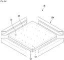
FIG. 6 is a perspective view illustrating the configuration of the vacuum glazing according to a second embodiment of the present invention,FIG. 7 is an exploded perspective view illustrating the configuration of the vacuum glazing according to the second embodiment of the present invention,FIG. 8 is a sectional view taken along line III-III' ofFIG. 6 , andFIGS. 9A to 9C are views illustrating a method for manufacturing the vacuum glazing according to the second embodiment of the present invention. - Referring to
FIGS. 6 to 9C , according to the second embodiment of the present invention, avacuum glazing 10a includes a plurality ofglazings frame 150 which is coupled to edge portions of the plurality ofglazings glazings glazings - The plurality of
glazings first glazing 110 and asecond glazing 120. The description of the first andsecond glazings - The
frame 150a may be configured to seal edge portions of the first andsecond glazings frame 150a may include a plurality of frame parts arranged along the edge portions of the first andsecond glazings - The four frame parts include a first frame part coupled to first edge portions of the first and
second plate glazings second plate glazings second plate glazings second plate glazings - The first to fourth frame parts may have the same configuration and the same shape. The
frame 150a may have the rectangular shape having an open inner portion depending on the arrangement of the first to fourth frame parts. In addition,coupling surfaces 155a may be formed on opposite side portions of each of the first frame part to the fourth frame part and coupled two adjacent frame parts. Thecoupling surface 155a may be configured to extend while being inclined with respect to four edges of the first andsecond glazings - The
frame 150a may include a metallic material, for example, a stainless material. The details thereof will be understood by citing the description of the first embodiment. - The first and
second glazings vacuum layer 180a may be formed in a space between the first andsecond glazings - In addition, a
spacer 130 may be interposed between the first andsecond glazings second glazings spacer 130 may be provided in thevacuum layer 180. The details of thespacer 130 may be understood by referring to the description of the first embodiment. - The
vacuum glazing 10a further includes anexhaust finishing member 140, anexhaust cap 145, and agas adsorbent 160 provided on thesecond glazing 120. The details thereof may be understood by referring to the description of the first embodiment. - The
frame 150a may be coupled to edges of the first andsecond glazings vacuum layer 180 may be maintained in a vacuum state. In other words, theframe 150a may constitute the end portion of thevacuum layer 180a. - The plurality of frame parts constituting the
frame 150a include afirst part 151a, asecond part 152a, and athird part 153a. Thefirst part 151a, thesecond part 152a, and thethird part 153a may be coupled to outer surfaces of the first andsecond glazings frame 150a may have a bending shape of "⊏" through the configuration of the first tothird parts - In detail, the
first part 151a may have a bent shape and be configured to be coupled to abottom surface 111 of thefirst glazing 110. In detail, thesecond part 152a may have a bent shape and be configured to be coupled to atop surface 121 of thefirst glazing 120. In addition, thethird part 153a may be configured to be coupled a firstlateral side surface 113 of thefirst glazing 110 and a secondlateral side surface 123 of thesecond glazing 120. - The thickness 't1' of the
frame 150a, that is, the thickness 't1' of each of the first tothird parts frame 150a is formed to be 0.2 mm or less, theframe 150a may be broken when theframe 150a is processed. In contrast, if the thickness 't1' of theframe 150 may be configured to be 1.0 mm or more, the heat transfer performance of theframe 150 may be increased, so the insulating performance of thevacuum glazing 10 may be lowered. - The left-right width of the
frame 150a, that is, the width 'w1' thebottom surface 111 of thefirst glazing 110, which is coupled to thefirst part 151a, may be formed in the range of 3-10 mm. The width 'w1' may be equal to the width of thetop surface part 121 of thesecond glazing 120, which is coupled to thesecond part 152a. - If the width 'w' of the
frame 150a is formed to be 3 mm or less, thesealant 170a is not compressed in the space between theframe 150a and the first andsecond glazings frame 150a is formed to be 10 mm or more, since heat may be excessively lost in the edge portions of the first andsecond glazings - The
sealant 170a may be further included in thevacuum glazing 10a. Thesealant 170a may be interposed between inner surfaces of the first tothird parts second glazings - In detail, the
sealant 170a may be interposed between thefirst part 151a and thebottom surface 111 of thefirst glazing 110. In detail, thesealant 170a may be interposed between thefirst part 152a and thetop surface 121 of thesecond glazing 120. In detail, thesealant 170a may be interposed between thethird part 153a, and at least a portion of the firstlateral side surface 113 and/or the secondlateral side surface 123. - The configuration of the
sealant 170a and the concept that theframe 150a having thesealant 170a is provided will be understood by referring to the description of the first embodiment. - The length of the
frame 150a may be relatively increased due to the configuration of the first tothird parts frame 150a and thus an amount of transferred heat may be reduced. - Hereinafter, the method for manufacturing the vacuum glazing according to the second embodiment will be described with reference to
FIGS. 9A to 9C . The description of the manufacturing method made with reference toFIGS. 5A to 5C of the description according to the first embodiment will be cited. - As shown in
FIGS. 5A to 5C , a plurality ofspacers 130 are installed on thefirst glazing 110 and thesecond glazing 120 is covered. Then, theframe 150a may be installed at the edge portions of the first andsecond glazings frame 150a may have thesealant 170a coated on the inner surface of theframe 150. - In detail, four frame parts constituting the
frame 150a may be arranged at respective edge portions of the first andsecond glazings second glazings coupling surface 155a provided on opposite side portions of each frame part may be coupled to coupling surfaces of two adjacent frame parts. - After the
frame 150a is assembled with the first andsecond glazings second glazings frame 150a is heated. In this heating procedure, thesealant 170a is melted and compressed to seal the space between the first andsecond glazings frame 150a (seeFIG. 9A ). - Thereafter, the
exhaust tube 128 is coupled to theexhaust hole 125 formed in thesecond glazing 120, and vacuum-pumping is performed through theexhaust tube 128. Accordingly, thevacuum layer 180a may be formed (seeFIG. 9B ). - After the
vacuum layer 180a is formed, theexhaust hole 125 is clogged by theexhaust finishing member 140, anexhaust cap 145 may be coupled to an outer portion of the exhaust finishing member 140 (seeFIG. 9C ). Through the manufacturing method, thevacuum glazing 10a may be easily manufactured. -
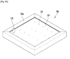
FIG. 10 is a perspective view illustrating the configuration of the vacuum glazing according to the third embodiment of the present invention,FIG. 11 is an exploded perspective view illustrating the configuration of the vacuum glazing according to the third embodiment of the present invention,FIG. 12 is a sectional view taken along line IV-IV' ofFIG. 10 , andFIGS. 13A to 13C are views illustrating a method for manufacturing the vacuum glazing according to the third embodiment of the present invention. - Referring to
FIGS. 10 to 13C , according to the third embodiment of the present invention, avacuum glazing 10b includes a plurality ofglazings frame 150b which is coupled to edge portions of the plurality ofglazings glazings glazings - The plurality of
glazings first glazing 110 and asecond glazing 120. The description of the first andsecond glazings - The
frame 150b may be configured to seal edge portions of the first andsecond glazings frame 150b may include a plurality offrame parts second glazings - For example, the plurality of frame parts include four frame parts. In detail, the four frame parts include a
first frame part 151b coupled to first edge portions of the first andsecond plate glazings second frame part 152b coupled to second edge portions of the first andsecond plate glazings third frame part 153b coupled to third edge portions of the first andsecond plate glazings fourth frame part 154b coupled to fourth edge portions of the first andsecond plate glazings - The plurality of
frame parts first frame part 151b may be separated from one side portion of the fourth frame part 151d. Theframe 150b may have the shape bent several times. Thefirst frame part 151b may be assembled with the fourth frame part 151d after theframe 150b is assembled with the first andsecond glazings - The first to
fourth frame parts frame 150a may have a rectangular shape having an open inner portion depending on the arrangement of the first to fourth frame parts. - The
frame 150b may include a metallic material, for example, a stainless material. The details thereof will be understood by referring to the description of the first embodiment. - The first and
second glazings vacuum layer 180b may be formed in a space between the first andsecond glazings - In addition, a
spacer 130 may be interposed between the first andsecond glazings second glazings spacer 130 may be interposed in thevacuum layer 180. The details of thespacer 130 may be understood by referring to the description of the first embodiment. - The
vacuum glazing 10b further includes anexhaust finishing member 140, anexhaust cap 145, and agas adsorbent 160 provided on thesecond glazing 120. The details thereof may be understood by referring to the description of the first embodiment. - The
frame 150a may be coupled to edges of the first andsecond glazings vacuum layer 180 may be maintained in a vacuum state. In other words, theframe 150a may constitute the edge portion of thevacuum layer 180a. - The first to
fourth frame parts lateral side surface 113 of thefirst glazing 110 and the secondlateral side surface 123 of thesecond glazing 120. - The thickness 't2' of the
frame 150b may be in the range of 0.2-1.0 mm. If the thickness 't2' of theframe 150b is formed to be 0.2 mm or less, theframe 150b may be broken when theframe 150b is processed. In contrast, if the thickness 't2' of theframe 150b may be configured to be 1.0 mm or more, the heat transfer performance of theframe 150b may be increased so that the insulating performance of thevacuum glazing 10b may be lowered. - The
sealant 170b may be further included in thevacuum glazing 10b. Thesealant 170b may be interposed between inner surfaces of the first tothird parts second glazings - In detail, the
sealant 170b may be interposed between the inner circumferential surfaces of theparts frame 150 and the firstlateral side surface 113 of thefirst glazing 110. In detail, thesealant 170b may be interposed between the inner circumferential surfaces of theparts frame 150 and the secondlateral side surface 123 of thesecond glazing 120. - The configuration of the
sealant 170b and the concept that theframe 150b having thesealant 170b is provided will be understood by citing the description of the first embodiment. - According to the configuration of the first to
fourth frame parts frame 150b is provided with contacting only the lateral side surfaces of the first andsecond glazings second glazings second glazings - Hereinafter, the method for manufacturing the vacuum glazing according to the third embodiment will be described with reference to
FIGS. 13A to 13C . The description of the manufacturing method made with reference toFIGS. 5A to 5C of the description according to the first embodiment will be cited in the present embodiment. - As shown in
FIGS. 5A to 5C , a plurality ofspacers 130 are installed on thefirst glazing 110 and thesecond glazing 120 is covered. Then, theframe 150b may be installed at the edge portions of the first andsecond glazings frame 150 may have thesealant 170b coated on the inner surface of theframe 150b. - In detail, four
frame parts frame 150a may be arranged at respective edge portions of the first andsecond glazings second glazings - After the
frame 150b is assembled with the first andsecond glazings second glazings frame 150b is heated. In this heating procedure, thesealant 170b is melted and compressed to seal the space between the first andsecond glazings frame 150b (seeFIG. 13A ). - Thereafter, the
exhaust tube 125 is coupled to theexhaust hole 125 formed in thesecond glazing 120, and vacuum-pumping is performed through theexhaust tube 128. Accordingly, thevacuum layer 180b may be formed (seeFIG. 13B ). - After the
vacuum layer 180b is formed, theexhaust hole 125 is clogged by theexhaust finishing member 140, anexhaust cap 145 may be coupled to an outer portion of the exhaust finishing member 140 (seeFIG. 5F ). Through the manufacturing method, thevacuum glazing 10b may be easily manufactured. -
FIG. 14 is a perspective view illustrating the configuration of the vacuum glazing according to a fourth embodiment of the present invention andFIG. 15 is an exploded perspective view illustrating the configuration of the vacuum glazing according to the fourth embodiment of the present invention.FIG. 16 is a sectional view taken along line V-V' ofFIG. 14 , andFIGS. 17A to 17D are views illustrating a method for manufacturing the vacuum glazing according to the third embodiment of the present invention. - Referring to
FIGS. 14 to 17D , according to the fourth embodiment of the present invention, avacuum glazing 10c includes a plurality ofglazings frame 150c which is interposed between the plurality ofglazings glazings glazings - The plurality of
glazings first glazing 110 and thesecond glazing 120. The description of the first andsecond glazings - The
frame 150c is compressed between the first andsecond glazings second glazings frame 150c includes a plurality offrame parts frame parts frame 150c may have the shape bent several times. - The first to
fourth frame parts frame 150c may have the shape of a rectangular frame having an open inner portion depending on the arrangement of the first to fourth frame parts. - The frame 15c may include a metallic material, for example, a stainless material. The details thereof will be understood by referring to the description of the first embodiment.
- The first and
second glazings vacuum layer 180c may be formed in a space between the first andsecond glazings - In addition, a
spacer 130 may be interposed between the first andsecond glazings second glazings spacer 130 may be interposed in thevacuum layer 180c. The details of thespacer 130 may be understood by referring to the description of the first embodiment. - The
vacuum glazing 10a further includes anexhaust finishing member 140, anexhaust cap 145, and agas adsorbent 160 provided on thesecond glazing 120. The details thereof may be understood by referring to the description of the first embodiment. - The
frame 150c may be coupled to edge portions of the first andsecond glazings vacuum layer 180 may be maintained in a vacuum state. In other words, theframe 150c may constitute the edge portion of thevacuum layer 180c. - The first to
fourth frame parts lateral side surface 114 of thefirst glazing 110 and the secondlateral side surface 124 of thesecond glazing 120. - The thickness 't3' of the
frame 150c may be in the range of 0.1-1.0 mm. If the thickness of theframe 150c is formed to be 0.1 mm or less, the vertical width of the vacuum layer 18c is significantly reduced and thus the insulating performance is degraded. In contrast, if the thickness 't3' of theframe 150c may be configured to be 1.0 mm or more, the heat transfer performance of theframe 150 may be increased so that the insulating performance of thevacuum glazing 10 may be lowered. - The left-right width of the
frame 150c, that is, the width 'w3' of atop surface 114 of thefirst glazing 110, which is coupled to theframe 150c, may be formed in the range of 3-10 mm. The width 'w3' may be equal to the width of thebottom surface 124 of thesecond glazing 120 couple to theframe 150c. - If the width 'w' of the
frame 150c is formed to be 3 mm or less, thesealant 170c is not compressed in the space between theframe 150c and the first andsecond glazings frame 150c is formed to be 10 mm or more, since heat may be excessively lost in the edges of the first andsecond glazings - The
sealant 170c may be further included in thevacuum glazing 10c. Thesealant 170c may be provided between bottom surfaces of the first tofourth frame parts top surface 114 of thefirst glazing 110, and may be provided between top surfaces of the first tofourth frame parts bottom surface 124 of thesecond glazing 120. - The configuration of the
sealant 170c and the concept that theframe 150c having thesealant 170c is provided will be understood by referring to the description of the first embodiment. - According to the configuration of the first to
fourth frame parts frame 150c may be interposed between the first andsecond glazings frame 150c may not be exposed out of the first andsecond glazings vacuum glazing 10c is used for the refrigerator door, the front surface and the rear surface of the door may be smooth. In addition, the interface with another component may not be made and the beautiful outer appearance may be made. - Hereinafter, the method for manufacturing the vacuum glazing according to the fourth embodiment will be described with reference to
FIGS. 17A to 17D . The description of the manufacturing method made with reference toFIGS. 5A and5B of the description according to the first embodiment will be cited in the present embodiment. - As illustrated in
FIGS. 5A and5B , after a plurality ofspacers 130 are installed on thefirst glazing 110, theframe 150c may be installed on the edge of the top surface of thefirst glazing 110. Theframe 150c may have asealant 170c coated on theframe 150c (seeFIG. 17A ). - The
second glazing 120 may be covered on theframe 150c (seeFIG. 17B ). After theframe 150c is interposed between the first andsecond glazings second glazings frame 150c is heated. In this heating procedure, thesealant 170c is melted and compressed to seal the space between the first andsecond glazings frame 150c (seeFIG. 17B ). - Thereafter, the
exhaust tube 128 is coupled to theexhaust hole 125 formed in thesecond glazing 120, and vacuum-pumping is performed through theexhaust tube 128. Accordingly, thevacuum layer 180c may be formed (seeFIG. 17C ). - After the
vacuum layer 180c is formed, theexhaust hole 125 is clogged by theexhaust finishing member 140, anexhaust cap 145 may be coupled to an outer portion of the exhaust finishing member 140 (seeFIG. 17D ). Through the manufacturing method, thevacuum glazing 10c may be easily manufactured. -
FIG. 18 is an experimental graph illustrating the comparison between insulating loads measured depending on the thickness of the frame according to the present invention. - The insulating performance may be varied depending on the thickness of the frame according to the embodiment of the present invention. In the above description, it is suggested that the thicknesses of the
frames - For example,
FIG. 18 is a graph showing the comparison between the related art and the second embodiment of the present invention. - Referring to
FIG. 18 , reference sign A on a horizontal axis represents that only the sealant is provided instead of the frame between the first and second glazings. A vertical axis represents an insulating load, that is, a heat transfer load value. Those skilled in the art may understand that an amount of transferred heat is increased if the insulating load is increased. - Reference signs B1 to B3 represent the thickness of the
frame 150a according to the second embodiment. In detail, reference sign B1 represents that the thickness t1 of theframe 150a is 0.2 mm, reference signal B2 represents that the thickness t1 of theframe 150a is 0.5 mm, and reference sign B3 represents that the thickness t1 of theframe 150a is 1.0 mm. - As known from the graph, reference signs B1 to B3 represent a less insulating load than reference sign A. In summary, according to the embodiment of the present invention, as compared to the related art, the insulting performance of the vacuum glazing may be improved.
Claims (15)
- A vacuum glazing comprising:a first glazing (110);a second glazing (120) provided at one side of the first glazing (110), the second glazing (120) being spaced apart from the first glazing (110);a vacuum layer (180) formed between the first glazing (110) and the second glazing (120);a spacer (130) provided in the vacuum layer to support the first glazing (110) and the second glazing (120);a frame (150, 150a, 150b, 150c) provided at edge portions of the first and second glazings (110, 120) and making contact with the first and second glazings (110, 120); anda sealant (170) interposed between the frame (150, 150a, 150b, 150c) and surfaces of the first and second glazings (110, 120) to perform sealing of the vacuum layer (180).
- The vacuum glazing of claim 1, wherein the frame (150, 150a, 150b, 150c) has a bent or rounded shape.
- The vacuum glazing of claim 1 or 2, wherein the frame (150, 150a, 150b) is coupled to lateral side surfaces of the first and second glazings (110, 120).
- The vacuum glazing of claim 3, wherein the frame (150, 150a) includes:a first part (151, 151a) coupled to a surface of the first glazing (110);a second part (152, 152a) coupled to a surface of the second glazing (120); anda third part (153, 153a) coupling the first part (151, 151a) to the second part (152, 152a, the third part having a bent or a rounded shape.
- The vacuum glazing of claim 4, wherein the frame (150, 150a) has a shape bent at least two times between the first part (151, 151a) and the third part (153, 153a), and
wherein the sealant (170) is provided at least in a space between the frame (150, 150a) and outer surfaces of the first and second glazings (110 120). - The vacuum glazing of claim 4 or 5, wherein the third part (153) has a bent or a rounded shape.
- The vacuum glazing of any one of claims 4 to 6, wherein the first and second parts (151, 152) are coupled to a bottom surface of the first glazing (110) and a top surface of the second glazing (120), respectively, and
wherein the third part (153) is spaced apart from lateral side surfaces of the first and second glazings (110, 120). - The vacuum glazing of any one of claims 4 to 7, further comprising:
a frame vacuum layer (182) interposed between the lateral side surfaces of the first and second glazings (110, 120) and an inner surface of the third part (153). - The vacuum glazing of claim 4 or 5, wherein the third part (153a) has a straight plane shape.
- The vacuum glazing of claim 1 or 2, wherein the frame (150c) is interposed between a top surface of the first glazing (110) and a bottom surface of the second glazing (120), and
wherein the sealant (170) is interposed between the frame (150c) and the top surface of the first glazing (110), and is interposed between the frame (150c) and the bottom surface of the second glazing (120). - The vacuum glazing of any one of claims 1 to 10, wherein the first and second glazings (110, 120) have rectangular shapes,
wherein the frame (150, 150a, 150b, 150c) includes:a first frame part disposed at first edge portions of the first and second glazings (110, 120);a second frame part disposed at second edge portions of the first and second glazings (110, 120);a third frame part disposed at third edge portions of the first and second glazings (110, 120); anda fourth frame part disposed at fourth side portions of the first and second glazings (110, 120). - The vacuum glazing of any one of claims 4 to 10, wherein a vertical width of the vacuum layer (180) is in a range of 0.18-0.22 mm, and
wherein each of parts of the first and second glazings (110, 120), which are coupled to the frame (150, 150a, 150c), has a lateral-width (w) in a range of 3-10 mm. - The vacuum glazing of claim 10, wherein a vertical thickness of the frame (150c) is in a range of 0.1-1.0 mm, and
wherein a vertical width of the vacuum layer (180) is in a range of 0.18-0.22 mm. - A method of manufacturing a vacuum glazing, the method comprising:installing a spacer (130) on a top surface of a first glazing (110);covering a second glazing (120) on the spacer (130);manufacturing a glazing assembly by coupling a frame (150, 150a, 150b, 150c) including a metallic material to edge portions of the first glazing (110) and the second glazing (120);sealing a space enclosed by the first glazing (110), the second glazing (120) and the frame (150, 150a, 150b, 150c) by heating the glazing assembly;forming a vacuum layer (180) in the space by pumping air out through an exhaust hole (125) in the second glazing (120); andfilling the exhaust hole (125) with an exhaust finishing material (140).
- The method of claim 14, further comprising:coating a sealant (170) on the frame (150, 150a, 150b, 150c) before coupling the frame to the edge portions of the first and second glazings (110, 120); andmelting the sealant (170) to be compressed between the first and second glazings (110, 120), and the frame (150, 150a, 150b, 150c), in a process of heating the glazing assembly.
Applications Claiming Priority (1)
| Application Number | Priority Date | Filing Date | Title |
|---|---|---|---|
| KR1020170163726A KR102068648B1 (en) | 2017-11-30 | 2017-11-30 | Vacuum glazing and manufacturing method the same |
Publications (2)
| Publication Number | Publication Date |
|---|---|
| EP3492681A1 true EP3492681A1 (en) | 2019-06-05 |
| EP3492681B1 EP3492681B1 (en) | 2025-07-30 |
Family
ID=64500227
Family Applications (1)
| Application Number | Title | Priority Date | Filing Date |
|---|---|---|---|
| EP18208525.8A Active EP3492681B1 (en) | 2017-11-30 | 2018-11-27 | Vacuum glazing |
Country Status (4)
| Country | Link |
|---|---|
| US (3) | US10676981B2 (en) |
| EP (1) | EP3492681B1 (en) |
| KR (1) | KR102068648B1 (en) |
| CN (3) | CN119320243A (en) |
Families Citing this family (6)
| Publication number | Priority date | Publication date | Assignee | Title |
|---|---|---|---|---|
| KR102068648B1 (en) * | 2017-11-30 | 2020-01-22 | 엘지전자 주식회사 | Vacuum glazing and manufacturing method the same |
| EP3879212A4 (en) * | 2018-11-08 | 2022-08-10 | LG Electronics Inc. | PANEL ARRANGEMENT, REFRIGERATOR AND HOUSEHOLD APPLIANCES |
| WO2020147908A1 (en) * | 2019-01-14 | 2020-07-23 | Vkr Holding A/S | Frame solution with gasket abutting vig unit surface |
| KR102439315B1 (en) | 2020-03-05 | 2022-09-02 | 이상백 | vacuum window |
| EP4164995A4 (en) * | 2020-06-11 | 2024-06-26 | V-Glass, Inc. | TWO-STAGE HERMETIC SEAL AND METHOD FOR MANUFACTURING THE SAME |
| KR102817456B1 (en) * | 2024-12-17 | 2025-06-10 | (주)종합건축사사무소 그룹케이 | Soundproof wall structure for apartment complexes |
Citations (4)
| Publication number | Priority date | Publication date | Assignee | Title |
|---|---|---|---|---|
| DE102007003962A1 (en) * | 2007-01-26 | 2008-07-31 | Peter Wasseroth | Sheet-edge bond for vacuum insulating glazing, which overstretches between glass panes in bent manner in cross section and closes in gas proof manner against outer atmosphere, has sheet bent, which is braced by beadings or shafts |
| KR20090036709A (en) | 2007-10-10 | 2009-04-15 | 주식회사 에피온 | Vacuum window glass and its manufacturing method |
| US20100178439A1 (en) * | 2009-01-15 | 2010-07-15 | Eversealed Windows, Inc. | Flexible edge seal for vacuum insulating glazing units |
| WO2012058938A1 (en) * | 2010-11-03 | 2012-05-10 | Luoyang Landglass Technology Co., Ltd. | Vacuum glass sealing method and vacuum glass product |
Family Cites Families (47)
| Publication number | Priority date | Publication date | Assignee | Title |
|---|---|---|---|---|
| US2157425A (en) * | 1937-04-24 | 1939-05-09 | Om Edwards Co Inc | Window construction |
| US2708774A (en) * | 1949-11-29 | 1955-05-24 | Rca Corp | Multiple glazed unit |
| US3389522A (en) * | 1966-04-20 | 1968-06-25 | Hordis Brothers | Glass unit and method |
| BE759898A (en) * | 1969-12-08 | 1971-05-17 | Marantier Bernard | IMPROVEMENTS TO FIXING DEVICES OF A VOLUME SUCH AS A GLASS OR GLASS, AND TO THE MOUNTING OF THESE DEVICES |
| JPS5718174Y2 (en) * | 1977-05-31 | 1982-04-16 | ||
| US4615159A (en) * | 1984-02-24 | 1986-10-07 | Gerald Kessler | Thermal window frame |
| US4952430A (en) * | 1985-05-16 | 1990-08-28 | Ppg Industries, Inc. | Insulated window units |
| JPH0684707B2 (en) * | 1985-11-29 | 1994-10-26 | ベヒリ・エミ−ル | Thermally insulating building elements and / or daylighting elements and methods for their production and apparatus for carrying out this method |
| US5131194A (en) * | 1989-05-08 | 1992-07-21 | Macarthur Company | Sound barrier window |
| WO1991001429A1 (en) * | 1989-07-16 | 1991-02-07 | Baechli Emil | Process for coating a glass surface |
| US5124185A (en) * | 1989-10-03 | 1992-06-23 | Ppg Industries, Inc. | Vacuum insulating unit |
| US5811926A (en) * | 1996-06-18 | 1998-09-22 | Ppg Industries, Inc. | Spacer units, image display panels and methods for making and using the same |
| MXPA99005203A (en) * | 1996-12-05 | 2006-07-18 | Sashlite Llc | Integrated multipane window unit and sash. |
| US6351923B1 (en) * | 1997-07-22 | 2002-03-05 | Wallace H. Peterson | Spacer for insulated windows having a lengthened thermal path |
| WO2001096255A1 (en) * | 2000-06-14 | 2001-12-20 | Nippon Sheet Glass Co., Ltd. | Glass panel |
| US6701749B2 (en) * | 2000-09-27 | 2004-03-09 | Guardian Industries Corp. | Vacuum IG window unit with edge seal at least partially diffused at temper and completed via microwave curing, and corresponding method of making the same |
| US6662523B2 (en) * | 2001-06-15 | 2003-12-16 | Sashlite, Llc | Insulating glass sash assemblies with adhesive mounting and spacing structures |
| AU2003229250A1 (en) * | 2002-09-13 | 2004-04-30 | Beo Technology Group Co., Ltd | High thermo and sound-insulating evacuated glass panel device |
| EP1883940A2 (en) * | 2005-05-06 | 2008-02-06 | David H. Stark | Insulated glazing units and methods |
| US20070116907A1 (en) * | 2005-11-18 | 2007-05-24 | Landon Shayne J | Insulated glass unit possessing room temperature-cured siloxane sealant composition of reduced gas permeability |
| DE102006061360A1 (en) * | 2006-12-22 | 2008-06-26 | Futech Gmbh | Heat-insulating glazing element, its manufacture and use |
| US7919157B2 (en) * | 2007-01-10 | 2011-04-05 | Guardian Industries Corp. | Vacuum IG window unit with metal member in hermetic edge seal |
| US7989040B2 (en) * | 2007-09-14 | 2011-08-02 | Electronics Packaging Solutions, Inc. | Insulating glass unit having multi-height internal standoffs and visible decoration |
| US8512829B2 (en) * | 2007-12-14 | 2013-08-20 | Guardian Industries Corp. | Metal-inclusive edge seal for vacuum insulating glass unit, and/or method of making the same |
| US8512830B2 (en) * | 2009-01-15 | 2013-08-20 | Eversealed Windows, Inc. | Filament-strung stand-off elements for maintaining pane separation in vacuum insulating glazing units |
| US9689195B2 (en) * | 2010-03-27 | 2017-06-27 | Robert S. Jones | Vacuum insulating glass unit with viscous edge seal |
| US9732552B2 (en) * | 2010-03-27 | 2017-08-15 | Robert S. Jones | Vacuum insulating glass unit with viscous edge seal |
| US8950162B2 (en) * | 2010-06-02 | 2015-02-10 | Eversealed Windows, Inc. | Multi-pane glass unit having seal with adhesive and hermetic coating layer |
| US9328512B2 (en) * | 2011-05-05 | 2016-05-03 | Eversealed Windows, Inc. | Method and apparatus for an insulating glazing unit and compliant seal for an insulating glazing unit |
| BE1020129A3 (en) * | 2011-08-03 | 2013-05-07 | Agc Glass Europe | GLAZING PANEL WITH PERIPHERAL SEALING AND CORRESPONDING MANUFACTURING METHOD. |
| KR101379061B1 (en) * | 2011-08-11 | 2014-03-28 | (주)엘지하우시스 | Heat strengthened vacuum glass |
| US9695628B2 (en) * | 2012-05-08 | 2017-07-04 | Guardian Industries Corp. | Vacuum insulated glass (VIG) window unit including pump-out tube protection ring and/or cap and methods for making same |
| US20130316099A1 (en) * | 2012-05-22 | 2013-11-28 | Eversealed Windows, Inc. | Stand-off construction for vacuum insulated glass |
| US8683775B1 (en) * | 2012-09-07 | 2014-04-01 | Guardian Industries Corp. | Spacer system for installing vacuum insulated glass (VIG) window unit in window frame designed to accommodate thicker IG window unit |
| US20140072735A1 (en) * | 2012-09-07 | 2014-03-13 | Guardian Industries Corp., | Spacer system for installing vacuum insulated glass (vig) window unit in window frame designed to accommodate thicker ig window unit |
| KR101402552B1 (en) | 2012-09-18 | 2014-06-02 | 주식회사 에피온 | Vacuum glass panel and method for manufacturing the same |
| US9441415B2 (en) * | 2012-12-27 | 2016-09-13 | Guardian Industries Corp. | Window having vacuum insulated glass (VIG) unit and frame including vacuum insulated structure(s) |
| EP2984052B1 (en) * | 2013-04-11 | 2018-12-26 | View, Inc. | Methods of fabricating a pressure compensated insulated glass unit |
| EP3191416A4 (en) * | 2013-10-18 | 2018-05-30 | Eversealed Windows, Inc. | Edge seal assemblies for hermetic insulating glass units and vacuum insulating glass units |
| KR101564143B1 (en) * | 2013-10-23 | 2015-10-28 | 한국과학기술원 | Vacuum insulation glass for reducing edge conduction |
| CN105669007A (en) * | 2014-11-19 | 2016-06-15 | 戴长虹 | Vacuum-glass heat-insulating board and manufacturing method thereof |
| CN204298238U (en) * | 2014-12-19 | 2015-04-29 | 洛阳兰迪玻璃机器股份有限公司 | A kind of sealing structure of vacuum glass and vacuum glass product thereof |
| CN204298239U (en) * | 2014-12-19 | 2015-04-29 | 洛阳兰迪玻璃机器股份有限公司 | A kind of sealing structure of vacuum glass and vacuum glass product thereof |
| ES2775186T3 (en) * | 2015-09-29 | 2020-07-24 | Panasonic Ip Man Co Ltd | Glass panel unit and glass window |
| KR101869604B1 (en) * | 2016-09-20 | 2018-07-20 | 박재일 | Method for manufacturing vacuum insulation glass panel assembly and device for manufacturing the same |
| EP3604245B1 (en) * | 2017-03-31 | 2023-07-26 | Panasonic Intellectual Property Management Co., Ltd. | Method for manufacturing glass panel unit and method for manufacturing glass window |
| KR102068648B1 (en) * | 2017-11-30 | 2020-01-22 | 엘지전자 주식회사 | Vacuum glazing and manufacturing method the same |
-
2017
- 2017-11-30 KR KR1020170163726A patent/KR102068648B1/en active Active
-
2018
- 2018-11-26 CN CN202411445628.2A patent/CN119320243A/en active Pending
- 2018-11-26 CN CN202411445631.4A patent/CN119320244A/en active Pending
- 2018-11-26 CN CN201811414658.1A patent/CN109851236A/en active Pending
- 2018-11-27 EP EP18208525.8A patent/EP3492681B1/en active Active
- 2018-11-30 US US16/206,569 patent/US10676981B2/en active Active
-
2020
- 2020-04-28 US US16/860,726 patent/US11236542B2/en active Active
-
2022
- 2022-01-04 US US17/568,308 patent/US11846135B2/en active Active
Patent Citations (4)
| Publication number | Priority date | Publication date | Assignee | Title |
|---|---|---|---|---|
| DE102007003962A1 (en) * | 2007-01-26 | 2008-07-31 | Peter Wasseroth | Sheet-edge bond for vacuum insulating glazing, which overstretches between glass panes in bent manner in cross section and closes in gas proof manner against outer atmosphere, has sheet bent, which is braced by beadings or shafts |
| KR20090036709A (en) | 2007-10-10 | 2009-04-15 | 주식회사 에피온 | Vacuum window glass and its manufacturing method |
| US20100178439A1 (en) * | 2009-01-15 | 2010-07-15 | Eversealed Windows, Inc. | Flexible edge seal for vacuum insulating glazing units |
| WO2012058938A1 (en) * | 2010-11-03 | 2012-05-10 | Luoyang Landglass Technology Co., Ltd. | Vacuum glass sealing method and vacuum glass product |
Also Published As
| Publication number | Publication date |
|---|---|
| EP3492681B1 (en) | 2025-07-30 |
| CN119320244A (en) | 2025-01-17 |
| KR20190064289A (en) | 2019-06-10 |
| US11236542B2 (en) | 2022-02-01 |
| US11846135B2 (en) | 2023-12-19 |
| US10676981B2 (en) | 2020-06-09 |
| CN119320243A (en) | 2025-01-17 |
| US20220127898A1 (en) | 2022-04-28 |
| CN109851236A (en) | 2019-06-07 |
| US20190162011A1 (en) | 2019-05-30 |
| US20200256114A1 (en) | 2020-08-13 |
| KR102068648B1 (en) | 2020-01-22 |
Similar Documents
| Publication | Publication Date | Title |
|---|---|---|
| EP3492681B1 (en) | Vacuum glazing | |
| JP4680998B2 (en) | Spacer profile for spacer frame and insulation window unit for insulation window unit | |
| US20140272208A1 (en) | Vacuum glass panel having getter filler and method of manufacturing same | |
| US8512829B2 (en) | Metal-inclusive edge seal for vacuum insulating glass unit, and/or method of making the same | |
| US6541084B2 (en) | Vacuum IG window unit with polymer spacers | |
| JP5373202B2 (en) | Method of sealing tempered vacuum glass and tempered vacuum glass | |
| US7919157B2 (en) | Vacuum IG window unit with metal member in hermetic edge seal | |
| JP6343283B2 (en) | Spacer system for installing vacuum insulated glass window units in window frames designed to accommodate thick insulated glass window units | |
| EP2627957B1 (en) | Vacuum insulation glass panel and refrigerator having the same | |
| CN108884700A (en) | Insulating glass units for refrigeration equipment | |
| CN105074113A (en) | Window having vacuum insulated glass (VIG) unit and frame including vacuum insulated structure (s) | |
| JP2018504536A (en) | Double glazing | |
| CN112984930B (en) | Insulated door components | |
| KR100990858B1 (en) | Vacuum window glass and its manufacturing method | |
| KR102169094B1 (en) | Vacuum glazing and manufacturing method the same | |
| EP3438398B1 (en) | Glass panel unit and fixture equipped with same | |
| KR102306143B1 (en) | Device for manufacturing a vacuum glazing | |
| JP2019529748A (en) | Modular system for multilayer insulation glazing unit, multilayer insulation glazing unit, and method for manufacturing the multilayer insulation glazing unit | |
| KR20190064292A (en) | Vacuum glazing, device for manufacturing the same and manufacturing method thereof | |
| US20070235441A1 (en) | Insulating glass unit construction with an electrically heated pane | |
| JP6893321B2 (en) | Manufacturing method of glass panel unit and fittings equipped with it | |
| US12084910B2 (en) | Apparatus for manufacturing vacuum glazing | |
| JP2001351547A (en) | Airtight vessel | |
| KR20200100021A (en) | Vacuum insulation glass and apparatus for manufacturing the same | |
| KR20070033110A (en) | Manufacturing method of field emission display device |
Legal Events
| Date | Code | Title | Description |
|---|---|---|---|
| PUAI | Public reference made under article 153(3) epc to a published international application that has entered the european phase |
Free format text: ORIGINAL CODE: 0009012 |
|
| STAA | Information on the status of an ep patent application or granted ep patent |
Free format text: STATUS: REQUEST FOR EXAMINATION WAS MADE |
|
| 17P | Request for examination filed |
Effective date: 20181227 |
|
| AK | Designated contracting states |
Kind code of ref document: A1 Designated state(s): AL AT BE BG CH CY CZ DE DK EE ES FI FR GB GR HR HU IE IS IT LI LT LU LV MC MK MT NL NO PL PT RO RS SE SI SK SM TR |
|
| AX | Request for extension of the european patent |
Extension state: BA ME |
|
| RBV | Designated contracting states (corrected) |
Designated state(s): AL AT BE BG CH CY CZ DE DK EE ES FI FR GB GR HR HU IE IS IT LI LT LU LV MC MK MT NL NO PL PT RO RS SE SI SK SM TR |
|
| RIC1 | Information provided on ipc code assigned before grant |
Ipc: E06B 3/663 20060101ALI20191220BHEP Ipc: E06B 3/66 20060101AFI20191220BHEP |
|
| STAA | Information on the status of an ep patent application or granted ep patent |
Free format text: STATUS: EXAMINATION IS IN PROGRESS |
|
| 17Q | First examination report despatched |
Effective date: 20200617 |
|
| GRAP | Despatch of communication of intention to grant a patent |
Free format text: ORIGINAL CODE: EPIDOSNIGR1 |
|
| STAA | Information on the status of an ep patent application or granted ep patent |
Free format text: STATUS: GRANT OF PATENT IS INTENDED |
|
| INTG | Intention to grant announced |
Effective date: 20250224 |
|
| GRAS | Grant fee paid |
Free format text: ORIGINAL CODE: EPIDOSNIGR3 |
|
| GRAA | (expected) grant |
Free format text: ORIGINAL CODE: 0009210 |
|
| STAA | Information on the status of an ep patent application or granted ep patent |
Free format text: STATUS: THE PATENT HAS BEEN GRANTED |
|
| AK | Designated contracting states |
Kind code of ref document: B1 Designated state(s): AL AT BE BG CH CY CZ DE DK EE ES FI FR GB GR HR HU IE IS IT LI LT LU LV MC MK MT NL NO PL PT RO RS SE SI SK SM TR |
|
| REG | Reference to a national code |
Ref country code: GB Ref legal event code: FG4D |
|
| REG | Reference to a national code |
Ref country code: CH Ref legal event code: EP |
|
| REG | Reference to a national code |
Ref country code: DE Ref legal event code: R096 Ref document number: 602018084026 Country of ref document: DE |
|
| REG | Reference to a national code |
Ref country code: IE Ref legal event code: FG4D |
|
| REG | Reference to a national code |
Ref country code: NL Ref legal event code: MP Effective date: 20250730 |
|
| REG | Reference to a national code |
Ref country code: AT Ref legal event code: MK05 Ref document number: 1819102 Country of ref document: AT Kind code of ref document: T Effective date: 20250730 |
|
| PG25 | Lapsed in a contracting state [announced via postgrant information from national office to epo] |
Ref country code: PT Free format text: LAPSE BECAUSE OF FAILURE TO SUBMIT A TRANSLATION OF THE DESCRIPTION OR TO PAY THE FEE WITHIN THE PRESCRIBED TIME-LIMIT Effective date: 20251202 |
|
| PG25 | Lapsed in a contracting state [announced via postgrant information from national office to epo] |
Ref country code: IS Free format text: LAPSE BECAUSE OF FAILURE TO SUBMIT A TRANSLATION OF THE DESCRIPTION OR TO PAY THE FEE WITHIN THE PRESCRIBED TIME-LIMIT Effective date: 20251130 |
|
| PGFP | Annual fee paid to national office [announced via postgrant information from national office to epo] |
Ref country code: DE Payment date: 20251002 Year of fee payment: 8 |
|
| PG25 | Lapsed in a contracting state [announced via postgrant information from national office to epo] |
Ref country code: NO Free format text: LAPSE BECAUSE OF FAILURE TO SUBMIT A TRANSLATION OF THE DESCRIPTION OR TO PAY THE FEE WITHIN THE PRESCRIBED TIME-LIMIT Effective date: 20251030 |
|
| REG | Reference to a national code |
Ref country code: LT Ref legal event code: MG9D |
|
| PG25 | Lapsed in a contracting state [announced via postgrant information from national office to epo] |
Ref country code: AT Free format text: LAPSE BECAUSE OF FAILURE TO SUBMIT A TRANSLATION OF THE DESCRIPTION OR TO PAY THE FEE WITHIN THE PRESCRIBED TIME-LIMIT Effective date: 20250730 |
|
| PG25 | Lapsed in a contracting state [announced via postgrant information from national office to epo] |
Ref country code: FI Free format text: LAPSE BECAUSE OF FAILURE TO SUBMIT A TRANSLATION OF THE DESCRIPTION OR TO PAY THE FEE WITHIN THE PRESCRIBED TIME-LIMIT Effective date: 20250730 |
|
| PGFP | Annual fee paid to national office [announced via postgrant information from national office to epo] |
Ref country code: IT Payment date: 20251021 Year of fee payment: 8 |
|
| PG25 | Lapsed in a contracting state [announced via postgrant information from national office to epo] |
Ref country code: NL Free format text: LAPSE BECAUSE OF FAILURE TO SUBMIT A TRANSLATION OF THE DESCRIPTION OR TO PAY THE FEE WITHIN THE PRESCRIBED TIME-LIMIT Effective date: 20250730 Ref country code: HR Free format text: LAPSE BECAUSE OF FAILURE TO SUBMIT A TRANSLATION OF THE DESCRIPTION OR TO PAY THE FEE WITHIN THE PRESCRIBED TIME-LIMIT Effective date: 20250730 |
|
| PGFP | Annual fee paid to national office [announced via postgrant information from national office to epo] |
Ref country code: FR Payment date: 20251001 Year of fee payment: 8 |
|
| PG25 | Lapsed in a contracting state [announced via postgrant information from national office to epo] |
Ref country code: GR Free format text: LAPSE BECAUSE OF FAILURE TO SUBMIT A TRANSLATION OF THE DESCRIPTION OR TO PAY THE FEE WITHIN THE PRESCRIBED TIME-LIMIT Effective date: 20251031 |
|
| PG25 | Lapsed in a contracting state [announced via postgrant information from national office to epo] |
Ref country code: SE Free format text: LAPSE BECAUSE OF FAILURE TO SUBMIT A TRANSLATION OF THE DESCRIPTION OR TO PAY THE FEE WITHIN THE PRESCRIBED TIME-LIMIT Effective date: 20250730 |
|
| PG25 | Lapsed in a contracting state [announced via postgrant information from national office to epo] |
Ref country code: LV Free format text: LAPSE BECAUSE OF FAILURE TO SUBMIT A TRANSLATION OF THE DESCRIPTION OR TO PAY THE FEE WITHIN THE PRESCRIBED TIME-LIMIT Effective date: 20250730 |
|
| PG25 | Lapsed in a contracting state [announced via postgrant information from national office to epo] |
Ref country code: BG Free format text: LAPSE BECAUSE OF FAILURE TO SUBMIT A TRANSLATION OF THE DESCRIPTION OR TO PAY THE FEE WITHIN THE PRESCRIBED TIME-LIMIT Effective date: 20250730 Ref country code: PL Free format text: LAPSE BECAUSE OF FAILURE TO SUBMIT A TRANSLATION OF THE DESCRIPTION OR TO PAY THE FEE WITHIN THE PRESCRIBED TIME-LIMIT Effective date: 20250730 |
|
| PG25 | Lapsed in a contracting state [announced via postgrant information from national office to epo] |
Ref country code: RS Free format text: LAPSE BECAUSE OF FAILURE TO SUBMIT A TRANSLATION OF THE DESCRIPTION OR TO PAY THE FEE WITHIN THE PRESCRIBED TIME-LIMIT Effective date: 20251030 |
|
| PG25 | Lapsed in a contracting state [announced via postgrant information from national office to epo] |
Ref country code: ES Free format text: LAPSE BECAUSE OF FAILURE TO SUBMIT A TRANSLATION OF THE DESCRIPTION OR TO PAY THE FEE WITHIN THE PRESCRIBED TIME-LIMIT Effective date: 20250730 |
|
| PG25 | Lapsed in a contracting state [announced via postgrant information from national office to epo] |
Ref country code: RO Free format text: LAPSE BECAUSE OF FAILURE TO SUBMIT A TRANSLATION OF THE DESCRIPTION OR TO PAY THE FEE WITHIN THE PRESCRIBED TIME-LIMIT Effective date: 20250730 |
|
| PG25 | Lapsed in a contracting state [announced via postgrant information from national office to epo] |
Ref country code: SM Free format text: LAPSE BECAUSE OF FAILURE TO SUBMIT A TRANSLATION OF THE DESCRIPTION OR TO PAY THE FEE WITHIN THE PRESCRIBED TIME-LIMIT Effective date: 20250730 |
|
| PG25 | Lapsed in a contracting state [announced via postgrant information from national office to epo] |
Ref country code: DK Free format text: LAPSE BECAUSE OF FAILURE TO SUBMIT A TRANSLATION OF THE DESCRIPTION OR TO PAY THE FEE WITHIN THE PRESCRIBED TIME-LIMIT Effective date: 20250730 |
|
| PG25 | Lapsed in a contracting state [announced via postgrant information from national office to epo] |
Ref country code: CZ Free format text: LAPSE BECAUSE OF FAILURE TO SUBMIT A TRANSLATION OF THE DESCRIPTION OR TO PAY THE FEE WITHIN THE PRESCRIBED TIME-LIMIT Effective date: 20250730 |
|
| PG25 | Lapsed in a contracting state [announced via postgrant information from national office to epo] |
Ref country code: EE Free format text: LAPSE BECAUSE OF FAILURE TO SUBMIT A TRANSLATION OF THE DESCRIPTION OR TO PAY THE FEE WITHIN THE PRESCRIBED TIME-LIMIT Effective date: 20250730 Ref country code: SK Free format text: LAPSE BECAUSE OF FAILURE TO SUBMIT A TRANSLATION OF THE DESCRIPTION OR TO PAY THE FEE WITHIN THE PRESCRIBED TIME-LIMIT Effective date: 20250730 |