EP3492433A1 - Membrane bioreactor system - Google Patents
Membrane bioreactor system Download PDFInfo
- Publication number
- EP3492433A1 EP3492433A1 EP18209127.2A EP18209127A EP3492433A1 EP 3492433 A1 EP3492433 A1 EP 3492433A1 EP 18209127 A EP18209127 A EP 18209127A EP 3492433 A1 EP3492433 A1 EP 3492433A1
- Authority
- EP
- European Patent Office
- Prior art keywords
- filtration
- bubble
- membrane
- bioreactor system
- hole
- Prior art date
- Legal status (The legal status is an assumption and is not a legal conclusion. Google has not performed a legal analysis and makes no representation as to the accuracy of the status listed.)
- Withdrawn
Links
- 239000012528 membrane Substances 0.000 title claims abstract description 107
- 238000001914 filtration Methods 0.000 claims abstract description 118
- 238000004140 cleaning Methods 0.000 claims abstract description 49
- 239000002351 wastewater Substances 0.000 claims abstract description 37
- QVGXLLKOCUKJST-UHFFFAOYSA-N atomic oxygen Chemical compound [O] QVGXLLKOCUKJST-UHFFFAOYSA-N 0.000 claims abstract description 15
- 229910052760 oxygen Inorganic materials 0.000 claims abstract description 15
- 239000001301 oxygen Substances 0.000 claims abstract description 15
- 239000012530 fluid Substances 0.000 claims description 7
- 238000004891 communication Methods 0.000 claims description 6
- 230000008878 coupling Effects 0.000 claims description 3
- 238000010168 coupling process Methods 0.000 claims description 3
- 238000005859 coupling reaction Methods 0.000 claims description 3
- 238000000926 separation method Methods 0.000 abstract description 15
- 238000005265 energy consumption Methods 0.000 abstract description 12
- 230000000694 effects Effects 0.000 abstract description 8
- 239000007788 liquid Substances 0.000 abstract description 8
- 238000005273 aeration Methods 0.000 description 47
- 230000000052 comparative effect Effects 0.000 description 20
- XLYOFNOQVPJJNP-UHFFFAOYSA-N water Substances O XLYOFNOQVPJJNP-UHFFFAOYSA-N 0.000 description 15
- 238000011084 recovery Methods 0.000 description 9
- VZSRBBMJRBPUNF-UHFFFAOYSA-N 2-(2,3-dihydro-1H-inden-2-ylamino)-N-[3-oxo-3-(2,4,6,7-tetrahydrotriazolo[4,5-c]pyridin-5-yl)propyl]pyrimidine-5-carboxamide Chemical compound C1C(CC2=CC=CC=C12)NC1=NC=C(C=N1)C(=O)NCCC(N1CC2=C(CC1)NN=N2)=O VZSRBBMJRBPUNF-UHFFFAOYSA-N 0.000 description 7
- 239000010410 layer Substances 0.000 description 5
- 238000000034 method Methods 0.000 description 5
- 239000011368 organic material Substances 0.000 description 5
- CURLTUGMZLYLDI-UHFFFAOYSA-N Carbon dioxide Chemical compound O=C=O CURLTUGMZLYLDI-UHFFFAOYSA-N 0.000 description 4
- 239000002033 PVDF binder Substances 0.000 description 4
- OAICVXFJPJFONN-UHFFFAOYSA-N Phosphorus Chemical compound [P] OAICVXFJPJFONN-UHFFFAOYSA-N 0.000 description 4
- 125000004122 cyclic group Chemical group 0.000 description 4
- 239000012510 hollow fiber Substances 0.000 description 4
- 238000009285 membrane fouling Methods 0.000 description 4
- 229910052698 phosphorus Inorganic materials 0.000 description 4
- 239000011574 phosphorus Substances 0.000 description 4
- 229920002492 poly(sulfone) Polymers 0.000 description 4
- 229920002239 polyacrylonitrile Polymers 0.000 description 4
- 229920002981 polyvinylidene fluoride Polymers 0.000 description 4
- IJGRMHOSHXDMSA-UHFFFAOYSA-N Atomic nitrogen Chemical compound N#N IJGRMHOSHXDMSA-UHFFFAOYSA-N 0.000 description 3
- 230000007423 decrease Effects 0.000 description 3
- 239000007787 solid Substances 0.000 description 3
- 238000004065 wastewater treatment Methods 0.000 description 3
- DEXFNLNNUZKHNO-UHFFFAOYSA-N 6-[3-[4-[2-(2,3-dihydro-1H-inden-2-ylamino)pyrimidin-5-yl]piperidin-1-yl]-3-oxopropyl]-3H-1,3-benzoxazol-2-one Chemical compound C1C(CC2=CC=CC=C12)NC1=NC=C(C=N1)C1CCN(CC1)C(CCC1=CC2=C(NC(O2)=O)C=C1)=O DEXFNLNNUZKHNO-UHFFFAOYSA-N 0.000 description 2
- 241000894006 Bacteria Species 0.000 description 2
- GRYLNZFGIOXLOG-UHFFFAOYSA-N Nitric acid Chemical compound O[N+]([O-])=O GRYLNZFGIOXLOG-UHFFFAOYSA-N 0.000 description 2
- IOVCWXUNBOPUCH-UHFFFAOYSA-N Nitrous acid Chemical compound ON=O IOVCWXUNBOPUCH-UHFFFAOYSA-N 0.000 description 2
- 239000004962 Polyamide-imide Substances 0.000 description 2
- 239000004695 Polyether sulfone Substances 0.000 description 2
- 239000004642 Polyimide Substances 0.000 description 2
- 238000011001 backwashing Methods 0.000 description 2
- 230000008901 benefit Effects 0.000 description 2
- 230000015572 biosynthetic process Effects 0.000 description 2
- 229910002092 carbon dioxide Inorganic materials 0.000 description 2
- 239000001569 carbon dioxide Substances 0.000 description 2
- 238000006243 chemical reaction Methods 0.000 description 2
- 239000002131 composite material Substances 0.000 description 2
- 239000000356 contaminant Substances 0.000 description 2
- 238000011109 contamination Methods 0.000 description 2
- 230000006866 deterioration Effects 0.000 description 2
- 239000000706 filtrate Substances 0.000 description 2
- 230000004907 flux Effects 0.000 description 2
- 230000003834 intracellular effect Effects 0.000 description 2
- VNWKTOKETHGBQD-UHFFFAOYSA-N methane Chemical compound C VNWKTOKETHGBQD-UHFFFAOYSA-N 0.000 description 2
- 229910017604 nitric acid Inorganic materials 0.000 description 2
- 229920003055 poly(ester-imide) Polymers 0.000 description 2
- 229920002312 polyamide-imide Polymers 0.000 description 2
- 229920006393 polyether sulfone Polymers 0.000 description 2
- 229920001721 polyimide Polymers 0.000 description 2
- 229920000642 polymer Polymers 0.000 description 2
- 230000000630 rising effect Effects 0.000 description 2
- 238000003786 synthesis reaction Methods 0.000 description 2
- 239000010409 thin film Substances 0.000 description 2
- YLZOPXRUQYQQID-UHFFFAOYSA-N 3-(2,4,6,7-tetrahydrotriazolo[4,5-c]pyridin-5-yl)-1-[4-[2-[[3-(trifluoromethoxy)phenyl]methylamino]pyrimidin-5-yl]piperazin-1-yl]propan-1-one Chemical compound N1N=NC=2CN(CCC=21)CCC(=O)N1CCN(CC1)C=1C=NC(=NC=1)NCC1=CC(=CC=C1)OC(F)(F)F YLZOPXRUQYQQID-UHFFFAOYSA-N 0.000 description 1
- MKYBYDHXWVHEJW-UHFFFAOYSA-N N-[1-oxo-1-(2,4,6,7-tetrahydrotriazolo[4,5-c]pyridin-5-yl)propan-2-yl]-2-[[3-(trifluoromethoxy)phenyl]methylamino]pyrimidine-5-carboxamide Chemical compound O=C(C(C)NC(=O)C=1C=NC(=NC=1)NCC1=CC(=CC=C1)OC(F)(F)F)N1CC2=C(CC1)NN=N2 MKYBYDHXWVHEJW-UHFFFAOYSA-N 0.000 description 1
- NIPNSKYNPDTRPC-UHFFFAOYSA-N N-[2-oxo-2-(2,4,6,7-tetrahydrotriazolo[4,5-c]pyridin-5-yl)ethyl]-2-[[3-(trifluoromethoxy)phenyl]methylamino]pyrimidine-5-carboxamide Chemical compound O=C(CNC(=O)C=1C=NC(=NC=1)NCC1=CC(=CC=C1)OC(F)(F)F)N1CC2=C(CC1)NN=N2 NIPNSKYNPDTRPC-UHFFFAOYSA-N 0.000 description 1
- AFCARXCZXQIEQB-UHFFFAOYSA-N N-[3-oxo-3-(2,4,6,7-tetrahydrotriazolo[4,5-c]pyridin-5-yl)propyl]-2-[[3-(trifluoromethoxy)phenyl]methylamino]pyrimidine-5-carboxamide Chemical compound O=C(CCNC(=O)C=1C=NC(=NC=1)NCC1=CC(=CC=C1)OC(F)(F)F)N1CC2=C(CC1)NN=N2 AFCARXCZXQIEQB-UHFFFAOYSA-N 0.000 description 1
- 239000004677 Nylon Substances 0.000 description 1
- 239000004952 Polyamide Substances 0.000 description 1
- 229940095054 ammoniac Drugs 0.000 description 1
- 230000003111 delayed effect Effects 0.000 description 1
- 230000002542 deteriorative effect Effects 0.000 description 1
- 229910001873 dinitrogen Inorganic materials 0.000 description 1
- 239000007789 gas Substances 0.000 description 1
- 239000012535 impurity Substances 0.000 description 1
- 238000009434 installation Methods 0.000 description 1
- 230000007774 longterm Effects 0.000 description 1
- 238000012423 maintenance Methods 0.000 description 1
- VUZPPFZMUPKLLV-UHFFFAOYSA-N methane;hydrate Chemical compound C.O VUZPPFZMUPKLLV-UHFFFAOYSA-N 0.000 description 1
- 244000005700 microbiome Species 0.000 description 1
- 230000001546 nitrifying effect Effects 0.000 description 1
- 229910052757 nitrogen Inorganic materials 0.000 description 1
- 229920001778 nylon Polymers 0.000 description 1
- 239000012466 permeate Substances 0.000 description 1
- 229920002647 polyamide Polymers 0.000 description 1
- 229920006149 polyester-amide block copolymer Polymers 0.000 description 1
- 230000008569 process Effects 0.000 description 1
- 238000005201 scrubbing Methods 0.000 description 1
- 239000002356 single layer Substances 0.000 description 1
- 238000004148 unit process Methods 0.000 description 1
Images


Classifications
-
- B—PERFORMING OPERATIONS; TRANSPORTING
- B01—PHYSICAL OR CHEMICAL PROCESSES OR APPARATUS IN GENERAL
- B01D—SEPARATION
- B01D65/00—Accessories or auxiliary operations, in general, for separation processes or apparatus using semi-permeable membranes
- B01D65/02—Membrane cleaning or sterilisation ; Membrane regeneration
-
- B—PERFORMING OPERATIONS; TRANSPORTING
- B01—PHYSICAL OR CHEMICAL PROCESSES OR APPARATUS IN GENERAL
- B01D—SEPARATION
- B01D63/00—Apparatus in general for separation processes using semi-permeable membranes
- B01D63/08—Flat membrane modules
-
- B—PERFORMING OPERATIONS; TRANSPORTING
- B01—PHYSICAL OR CHEMICAL PROCESSES OR APPARATUS IN GENERAL
- B01D—SEPARATION
- B01D63/00—Apparatus in general for separation processes using semi-permeable membranes
- B01D63/16—Rotary, reciprocated or vibrated modules
-
- B—PERFORMING OPERATIONS; TRANSPORTING
- B01—PHYSICAL OR CHEMICAL PROCESSES OR APPARATUS IN GENERAL
- B01F—MIXING, e.g. DISSOLVING, EMULSIFYING OR DISPERSING
- B01F23/00—Mixing according to the phases to be mixed, e.g. dispersing or emulsifying
- B01F23/20—Mixing gases with liquids
- B01F23/23—Mixing gases with liquids by introducing gases into liquid media, e.g. for producing aerated liquids
- B01F23/231—Mixing gases with liquids by introducing gases into liquid media, e.g. for producing aerated liquids by bubbling
- B01F23/23105—Arrangement or manipulation of the gas bubbling devices
- B01F23/2312—Diffusers
- B01F23/23121—Diffusers having injection means, e.g. nozzles with circumferential outlet
-
- C—CHEMISTRY; METALLURGY
- C02—TREATMENT OF WATER, WASTE WATER, SEWAGE, OR SLUDGE
- C02F—TREATMENT OF WATER, WASTE WATER, SEWAGE, OR SLUDGE
- C02F3/00—Biological treatment of water, waste water, or sewage
- C02F3/02—Aerobic processes
- C02F3/12—Activated sludge processes
- C02F3/1236—Particular type of activated sludge installations
- C02F3/1268—Membrane bioreactor systems
- C02F3/1273—Submerged membrane bioreactors
-
- C—CHEMISTRY; METALLURGY
- C02—TREATMENT OF WATER, WASTE WATER, SEWAGE, OR SLUDGE
- C02F—TREATMENT OF WATER, WASTE WATER, SEWAGE, OR SLUDGE
- C02F3/00—Biological treatment of water, waste water, or sewage
- C02F3/02—Aerobic processes
- C02F3/12—Activated sludge processes
- C02F3/20—Activated sludge processes using diffusers
-
- B—PERFORMING OPERATIONS; TRANSPORTING
- B01—PHYSICAL OR CHEMICAL PROCESSES OR APPARATUS IN GENERAL
- B01D—SEPARATION
- B01D2313/00—Details relating to membrane modules or apparatus
- B01D2313/26—Specific gas distributors or gas intakes
-
- B—PERFORMING OPERATIONS; TRANSPORTING
- B01—PHYSICAL OR CHEMICAL PROCESSES OR APPARATUS IN GENERAL
- B01D—SEPARATION
- B01D2315/00—Details relating to the membrane module operation
- B01D2315/04—Reciprocation, oscillation or vibration
-
- B—PERFORMING OPERATIONS; TRANSPORTING
- B01—PHYSICAL OR CHEMICAL PROCESSES OR APPARATUS IN GENERAL
- B01D—SEPARATION
- B01D2321/00—Details relating to membrane cleaning, regeneration, sterilization or to the prevention of fouling
- B01D2321/18—Use of gases
- B01D2321/185—Aeration
-
- B—PERFORMING OPERATIONS; TRANSPORTING
- B01—PHYSICAL OR CHEMICAL PROCESSES OR APPARATUS IN GENERAL
- B01D—SEPARATION
- B01D2321/00—Details relating to membrane cleaning, regeneration, sterilization or to the prevention of fouling
- B01D2321/20—By influencing the flow
- B01D2321/2033—By influencing the flow dynamically
- B01D2321/2058—By influencing the flow dynamically by vibration of the membrane, e.g. with an actuator
-
- B—PERFORMING OPERATIONS; TRANSPORTING
- B01—PHYSICAL OR CHEMICAL PROCESSES OR APPARATUS IN GENERAL
- B01F—MIXING, e.g. DISSOLVING, EMULSIFYING OR DISPERSING
- B01F2101/00—Mixing characterised by the nature of the mixed materials or by the application field
- B01F2101/305—Treatment of water, waste water or sewage
-
- B—PERFORMING OPERATIONS; TRANSPORTING
- B01—PHYSICAL OR CHEMICAL PROCESSES OR APPARATUS IN GENERAL
- B01F—MIXING, e.g. DISSOLVING, EMULSIFYING OR DISPERSING
- B01F2215/00—Auxiliary or complementary information in relation with mixing
- B01F2215/04—Technical information in relation with mixing
- B01F2215/0413—Numerical information
- B01F2215/0418—Geometrical information
- B01F2215/0431—Numerical size values, e.g. diameter of a hole or conduit, area, volume, length, width, or ratios thereof
-
- B—PERFORMING OPERATIONS; TRANSPORTING
- B01—PHYSICAL OR CHEMICAL PROCESSES OR APPARATUS IN GENERAL
- B01F—MIXING, e.g. DISSOLVING, EMULSIFYING OR DISPERSING
- B01F23/00—Mixing according to the phases to be mixed, e.g. dispersing or emulsifying
- B01F23/20—Mixing gases with liquids
- B01F23/23—Mixing gases with liquids by introducing gases into liquid media, e.g. for producing aerated liquids
- B01F23/231—Mixing gases with liquids by introducing gases into liquid media, e.g. for producing aerated liquids by bubbling
- B01F23/23105—Arrangement or manipulation of the gas bubbling devices
- B01F23/2312—Diffusers
- B01F23/23123—Diffusers consisting of rigid porous or perforated material
- B01F23/231231—Diffusers consisting of rigid porous or perforated material the outlets being in the form of perforations
-
- B—PERFORMING OPERATIONS; TRANSPORTING
- B01—PHYSICAL OR CHEMICAL PROCESSES OR APPARATUS IN GENERAL
- B01F—MIXING, e.g. DISSOLVING, EMULSIFYING OR DISPERSING
- B01F23/00—Mixing according to the phases to be mixed, e.g. dispersing or emulsifying
- B01F23/20—Mixing gases with liquids
- B01F23/23—Mixing gases with liquids by introducing gases into liquid media, e.g. for producing aerated liquids
- B01F23/231—Mixing gases with liquids by introducing gases into liquid media, e.g. for producing aerated liquids by bubbling
- B01F23/23105—Arrangement or manipulation of the gas bubbling devices
- B01F23/2312—Diffusers
- B01F23/23126—Diffusers characterised by the shape of the diffuser element
- B01F23/231265—Diffusers characterised by the shape of the diffuser element being tubes, tubular elements, cylindrical elements or set of tubes
-
- C—CHEMISTRY; METALLURGY
- C02—TREATMENT OF WATER, WASTE WATER, SEWAGE, OR SLUDGE
- C02F—TREATMENT OF WATER, WASTE WATER, SEWAGE, OR SLUDGE
- C02F2303/00—Specific treatment goals
- C02F2303/16—Regeneration of sorbents, filters
-
- Y—GENERAL TAGGING OF NEW TECHNOLOGICAL DEVELOPMENTS; GENERAL TAGGING OF CROSS-SECTIONAL TECHNOLOGIES SPANNING OVER SEVERAL SECTIONS OF THE IPC; TECHNICAL SUBJECTS COVERED BY FORMER USPC CROSS-REFERENCE ART COLLECTIONS [XRACs] AND DIGESTS
- Y02—TECHNOLOGIES OR APPLICATIONS FOR MITIGATION OR ADAPTATION AGAINST CLIMATE CHANGE
- Y02W—CLIMATE CHANGE MITIGATION TECHNOLOGIES RELATED TO WASTEWATER TREATMENT OR WASTE MANAGEMENT
- Y02W10/00—Technologies for wastewater treatment
- Y02W10/10—Biological treatment of water, waste water, or sewage
Definitions
- the present invention relates to a membrane bioreactor system, and more specifically, to a membrane bioreactor system which does not require a separate site for a membrane separation tank since a filtration apparatus for solid-liquid separation is provided in an aerobic tank and, when cleaning the membrane of the filtration apparatus, makes use of a portion of the fine bubbles supplied in the aerobic tank to increase the dissolved oxygen of the wastewater introduced into the aerobic tank, thereby minimizing the energy consumption while guaranteeing excellent membrane cleaning effect.
- a membrane bioreactor system (hereinafter, "MBR system”) is a wastewater treatment system which combines a biological treatment process and a membrane separation process in order to remove contaminants from the wastewater.
- a conventional MBR system comprises a flow control tank, an anoxic tank, an anaerobic tank, an aerobic tank, and a membrane separation tank.
- the anoxic tank and anaerobic tank may be omitted when the contaminants to be removed are mainly organic materials.
- the solids are accumulated on the surface of the filtration membrane, thereby causing a membrane fouling.
- the membrane fouling decreases a filtration efficiency.
- a membrane cleaning should be carried out so as to inhibit the membrane fouling.
- a fine bubble generator in the aerobic tank in order to increase the dissolved oxygen of the wastewater so that the wastewater treatment by microorganism can be performed well.
- the fine bubbles supplied from the fine bubble generator are required to have a diameter small enough to be able to easily dissolve in water so as to substantially increase the dissolved oxygen of the wastewater. Due to such a small size, the fine bubbles themselves are of little help to the membrane cleaning.
- the energy consumption of the blower in the continuous aeration is enormous to such an extent as to account for most of the entire energy consumption of the MBR system.
- Prior Art 2 Korean Patent Laid-Open Publication No. 10-2017-0121738 discloses a MBR system which performs solid-liquid separation by submerging a filtration membrane in an aerobic tank and cleans the membrane by mechanically reciprocating the filtration membrane in the aerobic tank rather than by performing an aeration cleaning using a blower and an aeration pipe.
- the present invention is directed to a MBR system which substantially obviate one or more problems due to limitations and disadvantages of the related art.
- An aspect of the present invention is to provide a membrane bioreactor system which does not require a separate site for a membrane separation tank since a filtration apparatus for solid-liquid separation is provided in an aerobic tank and, when cleaning the membrane of the filtration apparatus, makes use of a portion of the fine bubbles supplied in the aerobic tank to increase the dissolved oxygen of the wastewater introduced into the aerobic tank, thereby minimizing the energy consumption while guaranteeing excellent membrane cleaning effect.
- a MBR system comprising: an aerobic tank configured to receive a wastewater from at least one of a flow control tank, an anoxic tank and an anaerobic tank; a fine bubble generator disposed in the aerobic tank to increase a dissolved oxygen of the wastewater introduced into the aerobic tank; and a filtration apparatus submerged in the wastewater introduced into the aerobic tank, the filtration apparatus disposed directly above the fine bubble generator, wherein the filtration apparatus comprises: a filtration membrane module; and a bubble-converting device disposed below the filtration membrane module and configured to convert a portion of fine bubbles provided by the fine bubble generator into coarse bubbles suitable for filtration membrane cleaning, wherein the bubble-converting device comprises: a case having a lower opening and a collecting space configured to confine the portion of the fine bubbles introduced therein via the lower opening; a main pipe extending downwardly from a circumference of a first hole formed in an upper plate of the case; and a branch pipe extending from a circumference of a second hole formed in
- a diameter of the first hole may be 10 to 50 mm.
- the fine bubble generator may be configured to provide the fine bubbles having a diameter of 1 to 3 mm.
- the filtration apparatus may be disposed opposite a wastewater inlet of the aerobic tank in the aerobic tank.
- An opening of the branch pipe opposite to the second hole may be positioned closer to the upper plate of the case than the second hole.
- the opening of the branch pipe may face the upper plate of the case.
- the MBR system may further comprise a vibration apparatus configured to enable a rectilinear reciprocating movement of the filtration apparatus submerged in the wastewater.
- the vibration apparatus may comprise: a motor; a rotor rotatable by the motor; a shaft configured to convert a rotary motion of the rotor into a rectilinear reciprocating motion of the filtration apparatus; and a rail configured to guide the rectilinear reciprocating motion of the filtration apparatus.
- the filtration apparatus may further comprise a frame, and the filtration membrane module and the bubble-converting device may be respectively installed in the frame.
- the MBR system may further comprise a rod for coupling the bubble-converting device to the frame, the rod configured to enable the bubble-converting device to rotate on an axis of the rod within a predetermined angle range.
- the frame may comprise a lower horizontal member having a third hole, one end of the rod may be connected to the bubble-converting device, the other end of the rod may be inserted in the third hole of the lower horizontal member, and a lower part of the rod may have a curved cross section so that the rod can rotate in the third hole of the lower horizontal member within the predetermined angle range
- the MBR system of the present invention does not require separate aeration instruments such as a blower and an aeration pipe, and thus can minimize the energy consumption for the membrane cleaning without causing deterioration of the filtration efficiency.
- the cleaning effect can be maximized by, in addition to the membrane cleaning using the portion of the fine bubbles, vibrating the filtration apparatus when the filtration is performed.
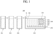
- FIG. 1 schematically shows a MBR system 200 according to an embodiment of the present invention.
- a MBR system 200 comprises a flow control tank 201, an anoxic tank 210, an anaerobic tank 220, and an aerobic tank 230.
- either of the anoxic tank 210 or the anaerobic tank 220 or both of them may be omitted depending on the objects and/or functions of the MBR system 200.
- the flow control tank 201 is generally for equalization of flow and water quality and, in some cases, may further function as a bioreactor.
- nitrous acid and/or nitric acid are/is reduced into nitrogen gas by denitrifying microbes and removed.
- organic materials are decomposed into methane gas and/or carbon dioxide by anaerobes and removed, and phosphorus accumulating bacterium releases phosphorus while performing intracellular synthesis of organic materials.
- organic materials are decomposed into carbon dioxide and water by aerobes, nitrification of ammoniac nitrogen into nitrous acid and/or nitric acid is carried out by nitrifying microbes, and phosphorus accumulating bacterium accumulates phosphorus again while decomposing the organic materials produced through intracellular synthesis.
- the wastewater from at least one of the flow control tank 201, anoxic tank 210, and anaerobic tank 220 is introduced into the aerobic tank 230.
- the wastewater passing through the flow control tank 201, anoxic tank 210, and anaerobic tank 220 sequentially is introduced into the aerobic tank 230
- the wastewater passing through the flow control tank 201, anaerobic tank 220, and anoxic tank 210 sequentially is introduced into the aerobic tank 230
- the wastewater passing through the flow control tank 201 and anoxic tank 210 sequentially is introduced into the aerobic tank 230
- the wastewater passing through the flow control tank 201 and anoxic tank 220 sequentially is introduced into the aerobic tank 230
- the wastewater passing through the flow control tank 201 and anaerobic tank 220 sequentially is introduced into the aerobic tank 230
- the wastewater passing through the flow control tank 201 is directly introduced into the aerobic tank 230.
- the MBR system 200 of the present invention further comprises a fine bubble generator 241 disposed in the aerobic tank 230.
- the fine bubble generator 241 receives an air from a blower 242 and generates fine bubbles FB, thereby increasing the dissolved oxygen of the wastewater in the aerobic tank 230.
- the fine bubbles FB supplied by the fine bubble generator 241 into the wastewater have a diameter small enough to be able to easily dissolve in the water, for example a diameter of 1 to 3 mm.
- the MBR system 200 of the present invention further comprises a filtration apparatus 100 which is submerged in the wastewater introduced in the aerobic tank 230 and carries out solid-liquid separation therein.
- the filtration apparatus 100 is disposed directly above the fine bubble generator 241 in the aerobic tank 230.
- the filtration apparatus 100 is provided in the aerobic tank 230, a separate site for a membrane separation tank is not additionally required.
- the filtration apparatus 100 of the present invention comprises a filtration membrane module 110 and a bubble-converting device 120 disposed below the filtration membrane module 110 and configured to convert a portion of fine bubbles FB provided by the fine bubble generator 241 into coarse bubbles CB suitable for membrane cleaning.
- the filtration membrane module 110 and the bubble-converting device 120 may be respectively installed in a frame 130.
- a portion of the fine bubbles supplied by the fine bubble generator 241 in the aerobic tank 230 in order to increase the dissolved oxygen of the wastewater are converted into the coarse bubbles CB by the bubble-converting device 120.
- a proper aeration cleaning can be performed using a portion of the fine bubbles FB supplied in the aerobic tank 230 without requiring installation and operation of a separate blower for an aeration cleaning, and thus the energy consumption can be remarkably reduced without deteriorating the filtration efficiency for the solid-liquid separation.
- the filtration apparatus 100 may be disposed opposite the wastewater inlet IL of the aerobic tank 230 in the aerobic tank 230 (i.e., at the latter part of the aerobic tank 230).
- the fine bubbles FB generated by the fine bubble generator 241 and supposed to be supplied to the wastewater positioned at the former part of the aerobic tank 230 are supplied thereto in their entirety so that the dissolved oxygen of the wastewater can be sufficiently increased and the wastewater treatment by microbes can be performed well.
- the fine bubbles FB supposed to be supplied to the wastewater positioned at the latter part of the aerobic tank 230 may be used for producing the coarse bubbles CB suitable for membrane cleaning.
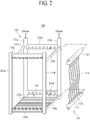
- FIG. 5 a filtration apparatus 100 according to the present invention will be described in more detail referring to FIG 2 to FIG. 5 .
- the filtration apparatus 100 of the present invention comprises at least one filtration membrane module 110 and at least one bubble-converting device 120 disposed below the filtration membrane module 110.
- the filtration membrane module 110 and the bubble-converting device 120 may be respectively installed in a frame 130.
- the filtration membrane module 110 comprises first and second headers 111 and 112 and a filtration membrane 113 positioned therebetween, the filtration membrane 113 being in fluid communication with at least one of the first and second headers 111 and 112.
- a hollow fiber membrane is illustrated in FIG. 1 as the filtration membrane 113, a flat sheet membrane may be adopted as the filtration membrane 113 in stead of a hollow fiber membrane.
- the filtration membrane 113 may be formed of polysulfone, polyether sulfone, sulfonated polysulfone, polyvinylidene fluoride (PVDF), polyacrylonitrile (PAN), polyimide, polyamideimide, polyesterimide, or any combination thereof.
- PVDF polyvinylidene fluoride
- PAN polyacrylonitrile
- the hollow fiber membrane which can be used as the filtration membrane 113 may be a single-layer membrane type or a composite membrane type.
- the hollow fiber membrane of a composite membrane type comprises a tubular braid and a polymer thin film coated on the outer surface thereof.
- the tubular braid may be made of polyester or polyamide (e.g., nylon), and the polymer thin film may be formed of polysulfone, polyether sulfone, sulfonated polysulfone, polyvinylidene fluoride (PVDF), polyacrylonitrile (PAN), polyimide, polyamideimide, polyesterimide, or any combination thereof.
- One end of the filtration membrane 113 is fixed to the first header 111 through a first fixing layer (not shown), and the other end thereof is fixed to the second header 112 through a second fixing layer (112a).
- At least one of the first and second headers 111 and 112 has a water collecting space therein, and the filtration membrane 113 is in fluid communication with the water collecting space.
- the frame 130 may comprise two vertical members 131a and 131b, two vertical pipes 132a and 132b, upper and lower cross bars 133a and 133b, upper and lower cross pipes 134a and 134b, two upper horizontal members 135a and 135b, and two lower horizontal members 136a and 136b.
- first and second headers 111 and 112 are coupled to and in fluid communication with the upper and lower cross pipes 134a and 134b, respectively, and the other ends thereof are coupled to the upper and lower cross bars 133a and 133b, respectively.
- the filtrate produced by the filtration membrane 113 flows into the upper and lower cross pipes 134a and 134b of the frame 130 via the first and second headers 111 and 112, and then is discharged out of the filtration apparatus 100 via at least one of the two vertical pipes 132a and 132b.
- the vertical pipes 132a and 132b may be replaced with vertical members without a fluid passage, and the filtrate introduced into the upper and lower cross pipes 134a and 134b may be discharged out of the filtration apparatus 100 via a separate pipe.
- both ends of the bubble-converting device 120 disposed below the filtration membrane module 110 may be directly or indirectly coupled to the lower horizontal members 136a and 136b, respectively.
- FIG. 3 schematically shows a bubble-converting device 120 of the present invention
- FIG. 4 shows the cross section of the bubble-converting device 120 along the IV-IV' line of FIG. 3 .
- the bubble-converting device 120 of the present invention comprises a case 121 having a lower opening LO.
- the case 121 comprises an upper plate 121a and side plates 121b extending downwardly from the circumference of the upper plate 121a.
- a collecting space CS surrounded by the upper plate 121a and side plates 121b is formed in the case 121. That is, the case 121 has a collecting space configured to confine the fine bubbles introduced therein via the lower opening LO. Accordingly, a portion of the fine bubbles FB supplied by the fine bubble generator 241 in the aerobic tank 230 may be confined in the collecting space CS of the case 121 and exploited for the aeration cleaning of the filtration membrane 113.
- the upper plate 121a of the case 121 has at least one first hole H1.
- the first holes H1 may be formed in the upper plate 121a along the longitudinal direction of the case 121.
- the bubble-converting device 120 of the present invention further comprises a main pipe 122 extending downwardly from the circumference of the first hole H1 formed in the upper plate 121 and a branch pipe 123 extending from a second hole H2 formed in a side of main pipe 122.
- the main pipe 122 is in fluid communication with the collecting space CS via the branch pipe 123.
- the opening PO of the branch pipe 123 disposed opposite to the second hole H2 may be positioned closer to the upper plate 121a of the case 121 than the second hole H2. Further, the opening PO of the branch pipe 123 may face the upper plate 121a.
- the filtration apparatus 100 of the present invention When the filtration apparatus 100 of the present invention is submerged in the feed water to perform a filtering operation, not only the inside of the case 121 of the bubble-converting device 120 but also the insides of the main pipe 122 and branch pipe 123 are filled with the feed water.
- the water surface WS in the case 121 continuously gets lower.
- the air confined in the collecting space moves into the main pipe 122 via the second hole H2 as shown in FIG. 5(B) , comes out of the bubble-converting device 120 via the first hole H1 of the case, and rises toward the filtration membrane module 110.
- the opening PO of the branch pipe 123 disposed opposite to the second hole H2 of the main pipe 122 may be positioned closer to the upper plate 121a of the case 121 than the second hole H2. Accordingly, once the air confined in the collecting space CS starts to come out of the bubble-converting device 120, as shown in FIG. 5(C) , the water surface WS in the case 121 rises and, until the water surface WS rising inside the case 121 reaches the same level as the opening PO of the branch pipe 123, the air is continuously discharged out of the bubble-converting device 120 in accordance with siphonage and forms coarse bubbles CB suitable for cleaning of the filtration membrane 113. Therefore, according to the present invention, the coarse bubbles CB for cleaning of the filtration membrane 113 can be provided without any additional supply of air by a blower, and thus the energy consumption for aeration cleaning can be minimized while guaranteeing the suitable cleaning effect.
- the first hole H1 may have a diameter of 3 to 30 mm.
- the diameter may be 10 to 50 mm which is larger than that of the aeration hole of the conventional aeration pipe (generally, about 7 mm).
- the MBR system 200 of the present invention may further comprise a vibration apparatus 250 configured to enable a rectilinear reciprocating movement of the filtration apparatus 100 submerged in the wastewater of the aerobic tank 230, thereby further maximizing the membrane cleaning efficiency.
- a vibration apparatus 250 configured to enable a rectilinear reciprocating movement of the filtration apparatus 100 submerged in the wastewater of the aerobic tank 230, thereby further maximizing the membrane cleaning efficiency.
- the filtration is vibrated in the wastewater so that the solids adhered to the surface of the filtration membrane 113 can be removed more easily.
- the vibration apparatus 250 may comprise a motor 251, a rotor 252 rotatable by the motor 251, a shaft configured to convert a rotary motion of the rotor into a rectilinear reciprocating motion of the filtration apparatus 100, and a rail 254 configured to guide the rectilinear reciprocating motion of the filtration apparatus 100.
- the motor 251 and the rotor 252 may be coupled to each other with a pulley and a belt.
- FIG. 7 illustrates a way how the lower horizontal member 136a of the frame 130 and the bubble-converting device 120 are coupled to each other according to an embodiment of the present invention.
- the filtration apparatus 100 of the present invention may further comprise a rod 124 for coupling the bubble-converting device 120 to the frame 130.
- the rod 124 may be configured to enable the bubble-converting device 120 to rotate on an axis of the rod 124 within a predetermined angle range.
- one end of the bubble-converting device 120 is connected to one end of the rod 124, and the other end of the rod 124 is inserted in the third hole H3 formed in the lower horizontal member 136a of the frame 130.
- the other end of the bubble-converting device 120 is also indirectly coupled to the opposite lower horizontal member 136b of the frame 130 similarly.
- the rod 124 and third hole H3 are configured to enable the bubble-converting device 120 to rotate on an axis of the rod 124 within a predetermined angle range.
- the lower part of the rod 124 may have a curved cross section so that the rod 124 can rotate in the third hole H3.
- the third hole H3 may have a cross section of such shape that the rod 124 can rotate therein only within a predetermined angle range (e.g., as illustrated in FIG. 7 , a circular cross section with the top part thereof cut out).
- the bubble-converting device 120 can rotate on the axis of the rod 124 with the predetermined angle range. Consequently, even before the air layer is formed within the collecting space CS in a volume large enough for the water surface WS in the case 121 to reach the same level as the second hole H2 formed in the side of the main pipe 122, a portion of the air layer can escape from the collecting space CS and form the coarse bubbles CB to contribute to the cleaning of the filtration membrane 113.
- a filtration apparatus illustrated in FIG. 2 (No. of filtration membrane modules: 38, membrane surface area of filtration membrane module: about 22.1 m 2 , total membrane surface area of filtration apparatus: about 840 m 2 ) was submerged in the wastewater of the aerobic tank and operated with permeate flux of 25 LMH(L/m 2 /h) for 14 days.
- the filtration was carried out by repeating a unit process (12 hours) consisting of the steps of repeating filtration (9 min.) and backwashing (0.5 min., backwashing flux: 37.5 LMH) 76 times and performing a maintenance cleaning using 200mg/L of NaOCI solution for 1 minute.
- the diameter of the aeration hole (i.e., 'the first hole (H1)') of the bubble-converting device was 50mm.
- the aeration rate per unit area of the filtration membrane (hereinafter, 'aeration rate') was 0.001 Nm 3 /min/m 2 .
- transmembrane pressure (TMP) rise of 0.007 bar was observed.
- a filtration was carried out in the same manner as in Example 1-1, except that the diameter of the aeration hole of the bubble-converting device was 30mm. During the operation of 14 days, TMP rise of 0.008 bar was observed.
- a filtration was carried out in the same manner as in Example 1-1, except that the diameter of the aeration hole of the bubble-converting device was 10mm. During the operation of 14 days, TMP rise of 0.009 bar was observed.
- a filtration was carried out in the same manner as in Example 1-1, except that the diameter of the aeration hole of the bubble-converting device was 7mm. During the operation of 14 days, TMP rise of 0.01 bar was observed.
- a filtration was carried out in the same manner as in Example 1-1, except that the diameter of the aeration hole of the bubble-converting device was 3mm. During the operation of 14 days, TMP rise of 0.03 bar was observed.
- a filtration was carried out in the same manner as in Example 1-1, except that the filtration apparatus was vibrated (amplitude: 10cm, reciprocating 0.6 times per 1 sec.) during the filtration operation. During the operation of 14 days, TMP rise of 0.005 bar was observed.
- a filtration was carried out in the same manner as in Example 2-1, except that the diameter of the aeration hole of the bubble-converting device was 30mm. During the operation of 14 days, TMP rise of 0.006 bar was observed.
- a filtration was carried out in the same manner as in Example 2-1, except that the diameter of the aeration hole of the bubble-converting device was 10mm. During the operation of 14 days, TMP rise of 0.007 bar was observed.
- a filtration was carried out in the same manner as in Example 2-1, except that the diameter of the aeration hole of the bubble-converting device was 7mm. During the operation of 14 days, TMP rise of 0.008 bar was observed.
- a filtration was carried out in the same manner as in Example 2-1, except that the diameter of the aeration hole of the bubble-converting device was 3mm. During the operation of 14 days, TMP rise of 0.022 bar was observed.
- a filtration was carried out in the same manner as in Example 1-1, except that the bubble-converting device of the filtration apparatus was replaced with a convention aeration pipe (aeration hole diameter: 7mm) and an air was continuously supplied by a blower to the aeration pipe in such an amount that the aeration rate could be 0.004 Nm 3 /min/m 2 .
- TMP rise of 0.01 bar was observed.
- a filtration was carried out in the same manner as in Comparative Example 1, except that the aeration rate was 0.003 Nm 3 /min/m 2 . During the operation of 14 days, TMP rise of 0.06 bar was observed.
- a filtration was carried out in the same manner as in Comparative Example 1, except that, instead of the continuous aeration, a cyclic aeration was performed by repeating air supply for 10 seconds and air non-supply for 10 seconds (i.e., the aeration rate was 0.002 Nm 3 /min/m 2 ). During the operation of 14 days, TMP rise of 0.012 bar was observed.
- a filtration was carried out in the same manner as in Comparative Example 3, except that the aeration rate was 0.001 Nm 3 /min/m 2 . During the operation of 14 days, TMP rise of 0.07 bar was observed.
- a filtration was carried out in the same manner as in Example 2-1, except that the bubble-converting device was removed from the filtration apparatus (i.e., the aeration rate was 0 Nm 3 /min/m 2 ). During the operation of 14 days, TMP rise of 0.015 bar was observed.
- TMP of a filtration membrane is critical TMP (0.6 bar) or higher, a recovery rate achievable by a recovery cleaning is considerably reduced. Therefore, before TMP of a filtration membrane reaches the critical TMP (0.6 bar), filtration needs to be stopped and recovery cleaning should be performed. Generally, the recovery cleaning is performed every 6 months in this industry. That is, TMP of a filtration membrane is required to be lower than the critical TMP (0.6 bar) even after six-month operation.
- TMP rise during the operation for 14 days is 0.06 bar as is the case of Comparative Example 2 or 0.07 bar as is the case of Comparative Example 4, it is more than likely that TMP of the filtration membrane after six-month operation would be higher than the critical TMP (0.6 bar) (theoretically, not less than 0.92 bar and not less than 1.04 bar, respectively). Therefore, the recovery cleaning cycle is required to be shorter than 6 months, which is problematic.
- Comparative Examples 1, 3, and 5 the TMP rises of which during 14-day operations were 0.01 bar, 0.012 bar, and 0.015 bar, respectively, are the cases in which the contamination of the filtration membranes was sufficiently delayed.
- Comparative Examples 1 and 3 relatively large amount of air (0.004 Nm 3 /min/m 2 and 0.002 Nm 3 /min/m 2 , respectively) was used, and thus such a large amount of energy was consumed for the aeration cleaning.
- Example 2-5 shows that the bubbles produced by a relatively small aeration hole may be a hindrance to the membrane cleaning. It seems to be because the bubbles produced by a relatively small aeration hole cannot provide sufficient shear force on the membrane surface and, by providing oxygen, cause a biofilm contamination by microbes on the membrane surface.
Landscapes
- Chemical & Material Sciences (AREA)
- Life Sciences & Earth Sciences (AREA)
- Chemical Kinetics & Catalysis (AREA)
- Biodiversity & Conservation Biology (AREA)
- Microbiology (AREA)
- Hydrology & Water Resources (AREA)
- Engineering & Computer Science (AREA)
- Environmental & Geological Engineering (AREA)
- Water Supply & Treatment (AREA)
- Organic Chemistry (AREA)
- Separation Using Semi-Permeable Membranes (AREA)
Abstract
Disclosed is a membrane bioreactor system capable of minimizing the energy consumption while guaranteeing excellent membrane cleaning effect. According to the membrane bioreactor system of the present invention, a filtration apparatus for solid-liquid separation is provided in an aerobic tank and a portion of fine bubbles supplied to increase the dissolved oxygen of wastewater introduced into the aerobic tank are used for cleaning the membrane of the filtration apparatus.
Description
- This application claims the benefit of the Korean Patent Application No.
10-2017-0164523 filed on December 1, 2017 - The present invention relates to a membrane bioreactor system, and more specifically, to a membrane bioreactor system which does not require a separate site for a membrane separation tank since a filtration apparatus for solid-liquid separation is provided in an aerobic tank and, when cleaning the membrane of the filtration apparatus, makes use of a portion of the fine bubbles supplied in the aerobic tank to increase the dissolved oxygen of the wastewater introduced into the aerobic tank, thereby minimizing the energy consumption while guaranteeing excellent membrane cleaning effect.
- A membrane bioreactor system (hereinafter, "MBR system") is a wastewater treatment system which combines a biological treatment process and a membrane separation process in order to remove contaminants from the wastewater.
- A conventional MBR system comprises a flow control tank, an anoxic tank, an anaerobic tank, an aerobic tank, and a membrane separation tank. The anoxic tank and anaerobic tank may be omitted when the contaminants to be removed are mainly organic materials.
- One of drawbacks of such conventional MBR system is that it requires a separate site for the membrane separation tank.
- In order to solve the problem, it has been suggested, for example by Korean Patent No.
10-0422211 - As the solid-liquid separation is performed by the filtration membrane, the solids are accumulated on the surface of the filtration membrane, thereby causing a membrane fouling. The membrane fouling decreases a filtration efficiency. Thus, a membrane cleaning should be carried out so as to inhibit the membrane fouling.
- Generally, there is provided a fine bubble generator in the aerobic tank in order to increase the dissolved oxygen of the wastewater so that the wastewater treatment by microorganism can be performed well. The fine bubbles supplied from the fine bubble generator are required to have a diameter small enough to be able to easily dissolve in water so as to substantially increase the dissolved oxygen of the wastewater. Due to such a small size, the fine bubbles themselves are of little help to the membrane cleaning.
- In Prior Art 1, in order to inhibit the membrane fouling, the air continuously supplied from a blower is strongly erupted through the holes of a aeration pipe, thereby forming coarse bubbles. While rising in the feed water, the coarse bubbles scrub the membrane surface, thereby removing the solids adhered to the surface.
- The energy consumption of the blower in the continuous aeration, however, is enormous to such an extent as to account for most of the entire energy consumption of the MBR system.
- In order to decrease the energy consumption of the blower, alternative methods (e.g., a cyclic aeration) to control the air supply timing of the blower and/or the amount of the air supplied by the blower have been suggested. If average air supply per unit time is excessively reduced only for the energy-saving purpose, the membrane is contaminated by the impurities more quickly and the filtration efficiency drops rapidly. Besides, further energy saving is still required in such alternative methods.
- Korean Patent Laid-Open Publication No.
10-2017-0121738 - Even though the cleaning method of Prior Art 2 requires relatively low energy consumption compared to that of Prior Art 1, however, it cannot delay the decline of cleaning efficiency as long as required in this field because the cleaning effect thereof is also relatively low.
- Accordingly, the present invention is directed to a MBR system which substantially obviate one or more problems due to limitations and disadvantages of the related art.
- An aspect of the present invention is to provide a membrane bioreactor system which does not require a separate site for a membrane separation tank since a filtration apparatus for solid-liquid separation is provided in an aerobic tank and, when cleaning the membrane of the filtration apparatus, makes use of a portion of the fine bubbles supplied in the aerobic tank to increase the dissolved oxygen of the wastewater introduced into the aerobic tank, thereby minimizing the energy consumption while guaranteeing excellent membrane cleaning effect.
- Additional aspects and features of the invention will be set forth in part in the description which follows and in part will become apparent to those having ordinary skill in the art upon examination of the following or may be learned from practice of the invention. The objectives and other advantages of the invention may be realized and attained by the structure particularly pointed out in the written description and claims hereof as well as the appended drawings.
- According to one aspect of the present invention, there is provided a MBR system comprising: an aerobic tank configured to receive a wastewater from at least one of a flow control tank, an anoxic tank and an anaerobic tank; a fine bubble generator disposed in the aerobic tank to increase a dissolved oxygen of the wastewater introduced into the aerobic tank; and a filtration apparatus submerged in the wastewater introduced into the aerobic tank, the filtration apparatus disposed directly above the fine bubble generator, wherein the filtration apparatus comprises: a filtration membrane module; and a bubble-converting device disposed below the filtration membrane module and configured to convert a portion of fine bubbles provided by the fine bubble generator into coarse bubbles suitable for filtration membrane cleaning, wherein the bubble-converting device comprises: a case having a lower opening and a collecting space configured to confine the portion of the fine bubbles introduced therein via the lower opening; a main pipe extending downwardly from a circumference of a first hole formed in an upper plate of the case; and a branch pipe extending from a circumference of a second hole formed in a side of the main pipe, and wherein the main pipe is in fluid communication with the collecting space via the branch pipe.
- A diameter of the first hole may be 10 to 50 mm.
- The fine bubble generator may be configured to provide the fine bubbles having a diameter of 1 to 3 mm.
- The filtration apparatus may be disposed opposite a wastewater inlet of the aerobic tank in the aerobic tank.
- An opening of the branch pipe opposite to the second hole may be positioned closer to the upper plate of the case than the second hole.
- The opening of the branch pipe may face the upper plate of the case.
- The MBR system may further comprise a vibration apparatus configured to enable a rectilinear reciprocating movement of the filtration apparatus submerged in the wastewater.
- The vibration apparatus may comprise: a motor; a rotor rotatable by the motor; a shaft configured to convert a rotary motion of the rotor into a rectilinear reciprocating motion of the filtration apparatus; and a rail configured to guide the rectilinear reciprocating motion of the filtration apparatus.
- The filtration apparatus may further comprise a frame, and the filtration membrane module and the bubble-converting device may be respectively installed in the frame.
- The MBR system may further comprise a rod for coupling the bubble-converting device to the frame, the rod configured to enable the bubble-converting device to rotate on an axis of the rod within a predetermined angle range.
- The frame may comprise a lower horizontal member having a third hole, one end of the rod may be connected to the bubble-converting device, the other end of the rod may be inserted in the third hole of the lower horizontal member, and a lower part of the rod may have a curved cross section so that the rod can rotate in the third hole of the lower horizontal member within the predetermined angle range
- According to the present invention, a portion of the fine bubbles supplied in an aerobic tank to increase the dissolved oxygen of an wastewater can be used for filtration membrane cleaning. Therefore, the MBR system of the present invention does not require separate aeration instruments such as a blower and an aeration pipe, and thus can minimize the energy consumption for the membrane cleaning without causing deterioration of the filtration efficiency.
- Furthermore, according to one embodiment of the present invention, the cleaning effect can be maximized by, in addition to the membrane cleaning using the portion of the fine bubbles, vibrating the filtration apparatus when the filtration is performed.
- It is to be understood that both the foregoing general description and the following detailed description of the present invention are exemplary and explanatory and are intended to provide further explanation of the invention as claimed.
- The accompanying drawings, which are included to provide a further understanding of the invention and are incorporated in and constitute a part of this application, illustrate embodiment(s) of the invention and together with the description serve to explain the principle of the invention. In the drawings:
-
FIG. 1 schematically shows a MBR system according to an embodiment of the present invention; -
FIG. 2 schematically shows a filtration apparatus according to an embodiment of the present invention; -
FIG. 3 schematically shows a bubble-converting device according to an embodiment of the present invention; -
FIG. 4 shows the cross section of the bubble-converting device along the IV-IV' line ofFIG. 3 ; -
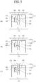
FIGs. 5(A) to 5(C) illustrate the operation of a bubble-converting device according to an embodiment of the present invention; -
FIG. 6 illustrates a vibration apparatus according to an embodiment of the present invention; and -
FIG. 7 illustrates a way how a lower horizontal member of a frame and a bubble-converting device are coupled to each other according to an embodiment of the present invention. - Reference will now be made in detail to the exemplary embodiments of the present invention, examples of which are illustrated in the accompanying drawings. Wherever possible, the same reference numbers will be used throughout the drawings to refer to the same or like parts.
-
FIG. 1 schematically shows aMBR system 200 according to an embodiment of the present invention. - As illustrated in
FIG. 1 , aMBR system 200 according to an embodiment of the present invention comprises aflow control tank 201, ananoxic tank 210, ananaerobic tank 220, and anaerobic tank 230. - Alternatively, either of the
anoxic tank 210 or theanaerobic tank 220 or both of them may be omitted depending on the objects and/or functions of theMBR system 200. - The
flow control tank 201 is generally for equalization of flow and water quality and, in some cases, may further function as a bioreactor. - In the
anoxic tank 210, nitrous acid and/or nitric acid are/is reduced into nitrogen gas by denitrifying microbes and removed. - In the
anaerobic tank 220, organic materials are decomposed into methane gas and/or carbon dioxide by anaerobes and removed, and phosphorus accumulating bacterium releases phosphorus while performing intracellular synthesis of organic materials. - In the
aerobic tank 230, organic materials are decomposed into carbon dioxide and water by aerobes, nitrification of ammoniac nitrogen into nitrous acid and/or nitric acid is carried out by nitrifying microbes, and phosphorus accumulating bacterium accumulates phosphorus again while decomposing the organic materials produced through intracellular synthesis. - According to the present invention, the wastewater from at least one of the
flow control tank 201,anoxic tank 210, andanaerobic tank 220 is introduced into theaerobic tank 230. For example, (i) as shown inFIG. 1 , the wastewater passing through theflow control tank 201,anoxic tank 210, andanaerobic tank 220 sequentially is introduced into theaerobic tank 230, (ii) the wastewater passing through theflow control tank 201,anaerobic tank 220, andanoxic tank 210 sequentially is introduced into theaerobic tank 230, (iii) the wastewater passing through theflow control tank 201 andanoxic tank 210 sequentially is introduced into theaerobic tank 230, (iv) the wastewater passing through theflow control tank 201 andanaerobic tank 220 sequentially is introduced into theaerobic tank 230, or (v) the wastewater passing through theflow control tank 201 is directly introduced into theaerobic tank 230. - The
MBR system 200 of the present invention further comprises afine bubble generator 241 disposed in theaerobic tank 230. Thefine bubble generator 241 receives an air from ablower 242 and generates fine bubbles FB, thereby increasing the dissolved oxygen of the wastewater in theaerobic tank 230. In order to substantially increase the dissolved oxygen of the wastewater, the fine bubbles FB supplied by thefine bubble generator 241 into the wastewater have a diameter small enough to be able to easily dissolve in the water, for example a diameter of 1 to 3 mm. - The
MBR system 200 of the present invention further comprises afiltration apparatus 100 which is submerged in the wastewater introduced in theaerobic tank 230 and carries out solid-liquid separation therein. Thefiltration apparatus 100 is disposed directly above thefine bubble generator 241 in theaerobic tank 230. - Therefore, according to the present invention, since the
filtration apparatus 100 is provided in theaerobic tank 230, a separate site for a membrane separation tank is not additionally required. - The
filtration apparatus 100 of the present invention comprises afiltration membrane module 110 and a bubble-convertingdevice 120 disposed below thefiltration membrane module 110 and configured to convert a portion of fine bubbles FB provided by thefine bubble generator 241 into coarse bubbles CB suitable for membrane cleaning. Thefiltration membrane module 110 and the bubble-convertingdevice 120 may be respectively installed in aframe 130. - According to the present invention, instead of using separate instruments such as a blower and an aeration pipe to produce coarse bubbles necessary for aeration cleaning, a portion of the fine bubbles supplied by the
fine bubble generator 241 in theaerobic tank 230 in order to increase the dissolved oxygen of the wastewater are converted into the coarse bubbles CB by the bubble-convertingdevice 120. - Thus, according to the present invention, a proper aeration cleaning can be performed using a portion of the fine bubbles FB supplied in the
aerobic tank 230 without requiring installation and operation of a separate blower for an aeration cleaning, and thus the energy consumption can be remarkably reduced without deteriorating the filtration efficiency for the solid-liquid separation. - The coarse bubbles CB suitable for membrane cleaning cannot make a substantial contribution to the increase of the dissolved oxygen of the wastewater because they rise rapidly in the wastewater. Therefore, according to one embodiment of the present invention, as illustrated in
FIG. 1 , thefiltration apparatus 100 may be disposed opposite the wastewater inlet IL of theaerobic tank 230 in the aerobic tank 230 (i.e., at the latter part of the aerobic tank 230). - In other words, since the biological reaction such as nitrification reaction occurs mainly at the former part of the
aerobic tank 230, the fine bubbles FB generated by thefine bubble generator 241 and supposed to be supplied to the wastewater positioned at the former part of theaerobic tank 230 are supplied thereto in their entirety so that the dissolved oxygen of the wastewater can be sufficiently increased and the wastewater treatment by microbes can be performed well. On the other hand, the fine bubbles FB supposed to be supplied to the wastewater positioned at the latter part of theaerobic tank 230 may be used for producing the coarse bubbles CB suitable for membrane cleaning. - Hereinafter, a
filtration apparatus 100 according to the present invention will be described in more detail referring toFIG 2 to FIG. 5 . - As illustrated in
FIG. 2 , thefiltration apparatus 100 of the present invention comprises at least onefiltration membrane module 110 and at least one bubble-convertingdevice 120 disposed below thefiltration membrane module 110. Thefiltration membrane module 110 and the bubble-convertingdevice 120 may be respectively installed in aframe 130. - The
filtration membrane module 110 comprises first andsecond headers filtration membrane 113 positioned therebetween, thefiltration membrane 113 being in fluid communication with at least one of the first andsecond headers FIG. 1 as thefiltration membrane 113, a flat sheet membrane may be adopted as thefiltration membrane 113 in stead of a hollow fiber membrane. - The
filtration membrane 113 may be formed of polysulfone, polyether sulfone, sulfonated polysulfone, polyvinylidene fluoride (PVDF), polyacrylonitrile (PAN), polyimide, polyamideimide, polyesterimide, or any combination thereof. - The hollow fiber membrane which can be used as the
filtration membrane 113 may be a single-layer membrane type or a composite membrane type. The hollow fiber membrane of a composite membrane type comprises a tubular braid and a polymer thin film coated on the outer surface thereof. The tubular braid may be made of polyester or polyamide (e.g., nylon), and the polymer thin film may be formed of polysulfone, polyether sulfone, sulfonated polysulfone, polyvinylidene fluoride (PVDF), polyacrylonitrile (PAN), polyimide, polyamideimide, polyesterimide, or any combination thereof. - One end of the
filtration membrane 113 is fixed to thefirst header 111 through a first fixing layer (not shown), and the other end thereof is fixed to thesecond header 112 through a second fixing layer (112a). - At least one of the first and
second headers filtration membrane 113 is in fluid communication with the water collecting space. - As illustrated in
FIG. 2 , theframe 130 may comprise twovertical members vertical pipes lower cross bars lower cross pipes horizontal members horizontal members - One ends of the first and
second headers lower cross pipes lower cross bars - The filtrate produced by the
filtration membrane 113 flows into the upper andlower cross pipes frame 130 via the first andsecond headers filtration apparatus 100 via at least one of the twovertical pipes - Alternatively, the
vertical pipes lower cross pipes filtration apparatus 100 via a separate pipe. - As illustrated in
FIG. 2 , both ends of the bubble-convertingdevice 120 disposed below thefiltration membrane module 110 may be directly or indirectly coupled to the lowerhorizontal members -
FIG. 3 schematically shows a bubble-convertingdevice 120 of the present invention, andFIG. 4 shows the cross section of the bubble-convertingdevice 120 along the IV-IV' line ofFIG. 3 . - As illustrated in
FIG. 3 and FIG. 4 , the bubble-convertingdevice 120 of the present invention comprises acase 121 having a lower opening LO. Thecase 121 comprises anupper plate 121a andside plates 121b extending downwardly from the circumference of theupper plate 121a. A collecting space CS surrounded by theupper plate 121a andside plates 121b is formed in thecase 121. That is, thecase 121 has a collecting space configured to confine the fine bubbles introduced therein via the lower opening LO. Accordingly, a portion of the fine bubbles FB supplied by thefine bubble generator 241 in theaerobic tank 230 may be confined in the collecting space CS of thecase 121 and exploited for the aeration cleaning of thefiltration membrane 113. - The
upper plate 121a of thecase 121 has at least one first hole H1. When theupper plate 121a has a plurality of first holes H1, as shown inFIG. 3 , the first holes H1 may be formed in theupper plate 121a along the longitudinal direction of thecase 121. - As illustrated in
FIG. 4 , the bubble-convertingdevice 120 of the present invention further comprises amain pipe 122 extending downwardly from the circumference of the first hole H1 formed in theupper plate 121 and abranch pipe 123 extending from a second hole H2 formed in a side ofmain pipe 122. Themain pipe 122 is in fluid communication with the collecting space CS via thebranch pipe 123. - The opening PO of the
branch pipe 123 disposed opposite to the second hole H2 may be positioned closer to theupper plate 121a of thecase 121 than the second hole H2. Further, the opening PO of thebranch pipe 123 may face theupper plate 121a. - Hereinafter, referring to
FIGs 5(A) to 5(C) , the operation of the bubble-convertingdevice 120 of the present invention will be described in detail. - When the
filtration apparatus 100 of the present invention is submerged in the feed water to perform a filtering operation, not only the inside of thecase 121 of the bubble-convertingdevice 120 but also the insides of themain pipe 122 andbranch pipe 123 are filled with the feed water. - As shown in
FIG. 5(A) , when the fine bubbles FB are supplied by thefine bubble generator 241 to increase the dissolved oxygen of the feed water, a portion of the fine bubbles FB are confined in the collecting space CS of thecase 121 of the bubble-convertingdevice 120, thereby forming an air layer. - As the fine bubbles FB are continuously supplied by the
fine bubble generator 241, the water surface WS in thecase 121 continuously gets lower. When the water surface WS reaches the same level as the second hole H2 formed in the side of themain pipe 122, the air confined in the collecting space moves into themain pipe 122 via the second hole H2 as shown inFIG. 5(B) , comes out of the bubble-convertingdevice 120 via the first hole H1 of the case, and rises toward thefiltration membrane module 110. - As mentioned above, the opening PO of the
branch pipe 123 disposed opposite to the second hole H2 of themain pipe 122 may be positioned closer to theupper plate 121a of thecase 121 than the second hole H2. Accordingly, once the air confined in the collecting space CS starts to come out of the bubble-convertingdevice 120, as shown inFIG. 5(C) , the water surface WS in thecase 121 rises and, until the water surface WS rising inside thecase 121 reaches the same level as the opening PO of thebranch pipe 123, the air is continuously discharged out of the bubble-convertingdevice 120 in accordance with siphonage and forms coarse bubbles CB suitable for cleaning of thefiltration membrane 113. Therefore, according to the present invention, the coarse bubbles CB for cleaning of thefiltration membrane 113 can be provided without any additional supply of air by a blower, and thus the energy consumption for aeration cleaning can be minimized while guaranteeing the suitable cleaning effect. - In order for the air discharged out of the bubble-converting
device 120 via the first hole H1 to be able to form coarse bubbles CB suitable for cleaning of thefiltration membrane 113, the first hole H1 may have a diameter of 3 to 30 mm. Preferably, in order to maximize the cleaning effect, the diameter may be 10 to 50 mm which is larger than that of the aeration hole of the conventional aeration pipe (generally, about 7 mm). - As illustrated in
FIG. 6 , theMBR system 200 of the present invention may further comprise avibration apparatus 250 configured to enable a rectilinear reciprocating movement of thefiltration apparatus 100 submerged in the wastewater of theaerobic tank 230, thereby further maximizing the membrane cleaning efficiency. In other words, in addition to the membrane surface scrubbing by the coarse bubbles CB, the filtration is vibrated in the wastewater so that the solids adhered to the surface of thefiltration membrane 113 can be removed more easily. - The
vibration apparatus 250 according to one embodiment of the present invention may comprise amotor 251, arotor 252 rotatable by themotor 251, a shaft configured to convert a rotary motion of the rotor into a rectilinear reciprocating motion of thefiltration apparatus 100, and arail 254 configured to guide the rectilinear reciprocating motion of thefiltration apparatus 100. - Alternatively, in order to control the rate of the rectilinear reciprocating motion, the
motor 251 and therotor 252 may be coupled to each other with a pulley and a belt. -
FIG. 7 illustrates a way how the lowerhorizontal member 136a of theframe 130 and the bubble-convertingdevice 120 are coupled to each other according to an embodiment of the present invention. - As illustrated in
FIG. 7 , thefiltration apparatus 100 of the present invention may further comprise arod 124 for coupling the bubble-convertingdevice 120 to theframe 130. Therod 124 may be configured to enable the bubble-convertingdevice 120 to rotate on an axis of therod 124 within a predetermined angle range. - Particularly, one end of the bubble-converting
device 120 is connected to one end of therod 124, and the other end of therod 124 is inserted in the third hole H3 formed in the lowerhorizontal member 136a of theframe 130. Although not shown inFIG. 7 , the other end of the bubble-convertingdevice 120 is also indirectly coupled to the opposite lowerhorizontal member 136b of theframe 130 similarly. - According to one embodiment of the present invention, the
rod 124 and third hole H3 are configured to enable the bubble-convertingdevice 120 to rotate on an axis of therod 124 within a predetermined angle range. For instance, the lower part of therod 124 may have a curved cross section so that therod 124 can rotate in the third hole H3. Further, the third hole H3 may have a cross section of such shape that therod 124 can rotate therein only within a predetermined angle range (e.g., as illustrated inFIG. 7 , a circular cross section with the top part thereof cut out). - Accordingly, when the
filtration apparatus 100 reciprocates, the bubble-convertingdevice 120 can rotate on the axis of therod 124 with the predetermined angle range. Consequently, even before the air layer is formed within the collecting space CS in a volume large enough for the water surface WS in thecase 121 to reach the same level as the second hole H2 formed in the side of themain pipe 122, a portion of the air layer can escape from the collecting space CS and form the coarse bubbles CB to contribute to the cleaning of thefiltration membrane 113. - Hereinafter, the present invention will be described in more detail with reference to the following Examples and Comparative Examples. The following Examples are only given for better understanding of the present invention and should not be construed as limiting the scope of the present invention.
- A filtration apparatus illustrated in
FIG. 2 (No. of filtration membrane modules: 38, membrane surface area of filtration membrane module: about 22.1 m2, total membrane surface area of filtration apparatus: about 840 m2) was submerged in the wastewater of the aerobic tank and operated with permeate flux of 25 LMH(L/m2/h) for 14 days. The filtration was carried out by repeating a unit process (12 hours) consisting of the steps of repeating filtration (9 min.) and backwashing (0.5 min., backwashing flux: 37.5 LMH) 76 times and performing a maintenance cleaning using 200mg/L of NaOCI solution for 1 minute. The diameter of the aeration hole (i.e., 'the first hole (H1)') of the bubble-converting device was 50mm. The aeration rate per unit area of the filtration membrane (hereinafter, 'aeration rate') was 0.001 Nm3/min/m2. During the operation of 14 days, transmembrane pressure (TMP) rise of 0.007 bar was observed. - A filtration was carried out in the same manner as in Example 1-1, except that the diameter of the aeration hole of the bubble-converting device was 30mm. During the operation of 14 days, TMP rise of 0.008 bar was observed.
- A filtration was carried out in the same manner as in Example 1-1, except that the diameter of the aeration hole of the bubble-converting device was 10mm. During the operation of 14 days, TMP rise of 0.009 bar was observed.
- A filtration was carried out in the same manner as in Example 1-1, except that the diameter of the aeration hole of the bubble-converting device was 7mm. During the operation of 14 days, TMP rise of 0.01 bar was observed.
- A filtration was carried out in the same manner as in Example 1-1, except that the diameter of the aeration hole of the bubble-converting device was 3mm. During the operation of 14 days, TMP rise of 0.03 bar was observed.
- A filtration was carried out in the same manner as in Example 1-1, except that the filtration apparatus was vibrated (amplitude: 10cm, reciprocating 0.6 times per 1 sec.) during the filtration operation. During the operation of 14 days, TMP rise of 0.005 bar was observed.
- A filtration was carried out in the same manner as in Example 2-1, except that the diameter of the aeration hole of the bubble-converting device was 30mm. During the operation of 14 days, TMP rise of 0.006 bar was observed.
- A filtration was carried out in the same manner as in Example 2-1, except that the diameter of the aeration hole of the bubble-converting device was 10mm. During the operation of 14 days, TMP rise of 0.007 bar was observed.
- A filtration was carried out in the same manner as in Example 2-1, except that the diameter of the aeration hole of the bubble-converting device was 7mm. During the operation of 14 days, TMP rise of 0.008 bar was observed.
- A filtration was carried out in the same manner as in Example 2-1, except that the diameter of the aeration hole of the bubble-converting device was 3mm. During the operation of 14 days, TMP rise of 0.022 bar was observed.
- A filtration was carried out in the same manner as in Example 1-1, except that the bubble-converting device of the filtration apparatus was replaced with a convention aeration pipe (aeration hole diameter: 7mm) and an air was continuously supplied by a blower to the aeration pipe in such an amount that the aeration rate could be 0.004 Nm3/min/m2. During the operation of 14 days, TMP rise of 0.01 bar was observed.
- A filtration was carried out in the same manner as in Comparative Example 1, except that the aeration rate was 0.003 Nm3/min/m2. During the operation of 14 days, TMP rise of 0.06 bar was observed.
- A filtration was carried out in the same manner as in Comparative Example 1, except that, instead of the continuous aeration, a cyclic aeration was performed by repeating air supply for 10 seconds and air non-supply for 10 seconds (i.e., the aeration rate was 0.002 Nm3/min/m2). During the operation of 14 days, TMP rise of 0.012 bar was observed.
- A filtration was carried out in the same manner as in Comparative Example 3, except that the aeration rate was 0.001 Nm3/min/m2. During the operation of 14 days, TMP rise of 0.07 bar was observed.
- A filtration was carried out in the same manner as in Example 2-1, except that the bubble-converting device was removed from the filtration apparatus (i.e., the aeration rate was 0 Nm3/min/m2). During the operation of 14 days, TMP rise of 0.015 bar was observed.
- The comparison of the membrane cleaning efficiencies of the Examples and Comparative Examples is shown in the following Table 1.
[Table 1] Cleaning Method Aeration Hole Diameter (mm) Aeration Rate (Nm3/min/m2) TMP Rise (bar) Ex. 1-1 bubble-converting 50 0.001 0.007 Ex. 1-2 bubble-converting 30 0.001 0.008 Ex. 1-3 bubble-converting 10 0.001 0.009 Ex. 1-4 bubble-converting 7 0.001 0.01 Ex. 1-5 bubble-converting 3 0.001 0.03 Ex. 2-1 bubble-converting & vibration 50 0.001 0.005 Ex. 2-2 bubble-converting & vibration 30 0.001 0.006 Ex. 2-3 bubble-converting & vibration 10 0.001 0.007 Ex. 2-4 bubble-converting & vibration 7 0.001 0.008 Ex. 2-5 bubble-converting & vibration 3 0.001 0.022 Comp. Ex. 1 continuous aeration 7 0.004 0.01 Comp. Ex. 2 continuous aeration 7 0.003 0.06 Comp. Ex. 3 cyclic aeration 7 0.002 0.012 Comp. Ex. 4 cyclic aeration 7 0.001 0.07 Comp. Ex. 5 vibration - 0 0.015 - As can be seen in Table 1, the TMP rises during the operation for 14 days were 0.06 bar and 0.07 bar in Comparative Example 2 and Comparative Example 4, respectively, which means that the filtration membranes were not cleaned properly and sufficiently.
- Generally, when TMP of a filtration membrane is critical TMP (0.6 bar) or higher, a recovery rate achievable by a recovery cleaning is considerably reduced. Therefore, before TMP of a filtration membrane reaches the critical TMP (0.6 bar), filtration needs to be stopped and recovery cleaning should be performed. Generally, the recovery cleaning is performed every 6 months in this industry. That is, TMP of a filtration membrane is required to be lower than the critical TMP (0.6 bar) even after six-month operation.
- Assuming the initial TMP of a filtration membrane is about 0.2 bar, if TMP rise during the operation for 14 days is 0.06 bar as is the case of Comparative Example 2 or 0.07 bar as is the case of Comparative Example 4, it is more than likely that TMP of the filtration membrane after six-month operation would be higher than the critical TMP (0.6 bar) (theoretically, not less than 0.92 bar and not less than 1.04 bar, respectively). Therefore, the recovery cleaning cycle is required to be shorter than 6 months, which is problematic.
- Comparative Examples 1, 3, and 5 the TMP rises of which during 14-day operations were 0.01 bar, 0.012 bar, and 0.015 bar, respectively, are the cases in which the contamination of the filtration membranes was sufficiently delayed. In Comparative Examples 1 and 3, however, relatively large amount of air (0.004 Nm3/min/m2 and 0.002 Nm3/min/m2, respectively) was used, and thus such a large amount of energy was consumed for the aeration cleaning. Further, considering the fact that a recovery rate achievable by a recovery cleaning gets lower as the recovery cleaning is repeated and Comparative Example 5 showed TMP rise of 0.015 bar which is greater than those of Comparative Examples 1 and 3, it is more than likely that, after a long term operation of more than 5 years, TMP of the filtration membrane of Comparative Example 5 reaches the critical TMP before the next recovery cleaning cycle comes, thereby requiring additional energy consumption.
- On the other hand, from the fact that only small TMP rise of no more than 0.005 to 0.022 occurred in spite of the relatively small amount of the air (0.001 Nm3/min/m2) and the fine bubbles originally supplied in the aerobic tank were used for the membrane cleaning without an additional air from any other source, it can be seen that the energy consumptions of the Examples for the aeration cleaning were minimized without deterioration of the cleaning efficiency.
- Particularly, in Examples 1-1, 1-2, 1-3, 2-1, 2-2, and 2-3 where the diameters of the aeration holes were 10mm or longer, the cleaning effects were so excellent that TMP rises of less than 0.01 bar were only observed.
- Comparison of Example 2-5 with Comparative Example 5 shows that the bubbles produced by a relatively small aeration hole may be a hindrance to the membrane cleaning. It seems to be because the bubbles produced by a relatively small aeration hole cannot provide sufficient shear force on the membrane surface and, by providing oxygen, cause a biofilm contamination by microbes on the membrane surface.
Claims (11)
- A membrane bioreactor system comprising:an aerobic tank configured to receive a wastewater from at least one of a flow control tank, an anoxic tank and an anaerobic tank;a fine bubble generator disposed in the aerobic tank to increase a dissolved oxygen of the wastewater introduced into the aerobic tank; anda filtration apparatus submerged in the wastewater introduced into the aerobic tank, the filtration apparatus disposed directly above the fine bubble generator,wherein the filtration apparatus comprises:a filtration membrane module; anda bubble-converting device disposed below the filtration membrane module and configured to convert a portion of fine bubbles provided by the fine bubble generator into coarse bubbles suitable for filtration membrane cleaning,wherein the bubble-converting device comprises:a case having a lower opening and a collecting space configured to confine the portion of the fine bubbles introduced therein via the lower opening;a main pipe extending downwardly from a circumference of a first hole formed in an upper plate of the case; anda branch pipe extending from a circumference of a second hole formed in a side of the main pipe, andwherein the main pipe is in fluid communication with the collecting space via the branch pipe.
- The membrane bioreactor system of claim 1, wherein a diameter of the first hole is 10 to 50 mm.
- The membrane bioreactor system of claim 2, wherein the fine bubble generator is configured to provide the fine bubbles having a diameter of 1 to 3 mm.
- The membrane bioreactor system of claim 1, wherein the filtration apparatus is disposed opposite a wastewater inlet of the aerobic tank in the aerobic tank.
- The membrane bioreactor system of claim 1, wherein an opening of the branch pipe opposite to the second hole is positioned closer to the upper plate of the case than the second hole.
- The membrane bioreactor system of claim 5, wherein the opening of the branch pipe faces the upper plate of the case.
- The membrane bioreactor system of claim 1, further comprising a vibration apparatus configured to enable a rectilinear reciprocating movement of the filtration apparatus submerged in the wastewater.
- The membrane bioreactor system of claim 7, wherein the vibration apparatus comprises:a motor;a rotor rotatable by the motor;a shaft configured to convert a rotary motion of the rotor into a rectilinear reciprocating motion of the filtration apparatus; anda rail configured to guide the rectilinear reciprocating motion of the filtration apparatus.
- The membrane bioreactor system of claim 7, wherein the filtration apparatus further comprises a frame, and the filtration membrane module and the bubble-converting device are respectively installed in the frame.
- The membrane bioreactor system of claim 9, further comprising a rod for coupling the bubble-converting device to the frame, the rod configured to enable the bubble-converting device to rotate on an axis of the rod within a predetermined angle range.
- The membrane bioreactor system of claim 10, wherein the frame comprises a lower horizontal member having a third hole, one end of the rod is connected to the bubble-converting device, the other end of the rod is inserted in the third hole of the lower horizontal member, and a lower part of the rod has a curved cross section so that the rod can rotate in the third hole of the lower horizontal member within the predetermined angle range.
Applications Claiming Priority (1)
| Application Number | Priority Date | Filing Date | Title |
|---|---|---|---|
| KR20170164523 | 2017-12-01 |
Publications (1)
| Publication Number | Publication Date |
|---|---|
| EP3492433A1 true EP3492433A1 (en) | 2019-06-05 |
Family
ID=64559523
Family Applications (1)
| Application Number | Title | Priority Date | Filing Date |
|---|---|---|---|
| EP18209127.2A Withdrawn EP3492433A1 (en) | 2017-12-01 | 2018-11-29 | Membrane bioreactor system |
Country Status (3)
| Country | Link |
|---|---|
| US (1) | US20190168165A1 (en) |
| EP (1) | EP3492433A1 (en) |
| KR (1) | KR20190065140A (en) |
Families Citing this family (7)
| Publication number | Priority date | Publication date | Assignee | Title |
|---|---|---|---|---|
| CN113491953B (en) * | 2021-07-15 | 2023-08-01 | 杭州求是膜技术有限公司 | Opposed cross-flow flushing type vibrating diaphragm device |
| KR102681393B1 (en) * | 2021-11-29 | 2024-07-04 | (주)하이필엠 | Filtration Apparatus and Filtration System Comprising The Same |
| CN115196743A (en) * | 2022-05-27 | 2022-10-18 | 祝妍华 | Sewage treatment equipment with high-efficiency aeration device and method |
| WO2024143977A1 (en) * | 2022-12-29 | 2024-07-04 | 한국건설기술연구원 | Method for separating out solid materials in environmental sample by using ultra-fine bubbles and vibration impactor, and automatic sampler using same |
| KR102711493B1 (en) * | 2023-03-31 | 2024-09-26 | (주)하이필엠 | Water Treatment System |
| KR20250156348A (en) | 2024-04-25 | 2025-11-03 | 대한민국(환경부 국립생물자원관장) | Culture Device for Enrichment Culture of Methanotroph Using Membrane Biofilm Reactor |
| CN119118348B (en) * | 2024-09-29 | 2026-06-19 | 福建创投环保科技有限公司 | MBR (Membrane bioreactor) for wastewater dephosphorization |
Citations (5)
| Publication number | Priority date | Publication date | Assignee | Title |
|---|---|---|---|---|
| KR100422211B1 (en) | 2000-12-06 | 2004-03-12 | 대한통운 주식회사 | Management Unit and Method of Foul and Waste Water |
| WO2012134127A2 (en) * | 2011-03-31 | 2012-10-04 | 코오롱인더스트리 주식회사 | Filtration membrane module and filtration system including same |
| EP2960213A2 (en) * | 2012-10-08 | 2015-12-30 | Doosan Heavy Industries & Construction Co., Ltd. | Membrane bioreactor system using a reciprocating membrane |
| WO2016064466A1 (en) * | 2014-10-22 | 2016-04-28 | Koch Membrane Systems, Inc. | Membrane module system with bundle enclosures and pulsed aeration and method of operation |
| KR20170121738A (en) | 2015-08-24 | 2017-11-02 | 두산중공업 주식회사 | Water Treatment System Containing with Reciprocating Submerged Membrane |
Family Cites Families (2)
| Publication number | Priority date | Publication date | Assignee | Title |
|---|---|---|---|---|
| US6616843B1 (en) * | 1998-12-18 | 2003-09-09 | Omnium De Traitement Et De Valorisation | Submerged membrane bioreactor for treatment of nitrogen containing water |
| WO2011100320A2 (en) * | 2010-02-09 | 2011-08-18 | Aquatech International Corporation | Advanced filtration device for water and wastewater treatment |
-
2018
- 2018-11-29 EP EP18209127.2A patent/EP3492433A1/en not_active Withdrawn
- 2018-11-29 KR KR1020180150289A patent/KR20190065140A/en not_active Withdrawn
- 2018-11-30 US US16/205,713 patent/US20190168165A1/en not_active Abandoned
Patent Citations (5)
| Publication number | Priority date | Publication date | Assignee | Title |
|---|---|---|---|---|
| KR100422211B1 (en) | 2000-12-06 | 2004-03-12 | 대한통운 주식회사 | Management Unit and Method of Foul and Waste Water |
| WO2012134127A2 (en) * | 2011-03-31 | 2012-10-04 | 코오롱인더스트리 주식회사 | Filtration membrane module and filtration system including same |
| EP2960213A2 (en) * | 2012-10-08 | 2015-12-30 | Doosan Heavy Industries & Construction Co., Ltd. | Membrane bioreactor system using a reciprocating membrane |
| WO2016064466A1 (en) * | 2014-10-22 | 2016-04-28 | Koch Membrane Systems, Inc. | Membrane module system with bundle enclosures and pulsed aeration and method of operation |
| KR20170121738A (en) | 2015-08-24 | 2017-11-02 | 두산중공업 주식회사 | Water Treatment System Containing with Reciprocating Submerged Membrane |
Also Published As
| Publication number | Publication date |
|---|---|
| KR20190065140A (en) | 2019-06-11 |
| US20190168165A1 (en) | 2019-06-06 |
Similar Documents
| Publication | Publication Date | Title |
|---|---|---|
| US20190168165A1 (en) | Membrane bioreactor system | |
| EP2960213B1 (en) | Membrane bioreactor system using a reciprocating membrane | |
| US8528745B2 (en) | Membrane supported biofilm apparatus | |
| JP5908186B2 (en) | Water treatment method and water treatment apparatus using membrane | |
| JP2008264772A (en) | Membrane separation activated sludge apparatus and method for treating water containing organic matter | |
| JP5467793B2 (en) | Operation method of submerged membrane separator | |
| JP2014503349A (en) | Method, apparatus and membrane bioreactor for wastewater treatment | |
| JP2010069361A (en) | Membrane washing apparatus, membrane separation apparatus, and wastewater treatment apparatus | |
| US20200189948A1 (en) | Wastewater Treatment System and Method | |
| EP3124105A1 (en) | Filtering apparatus | |
| WO2005118115A1 (en) | Network for supporting spiral wound membrane cartridges for submerged operation | |
| KR101798551B1 (en) | Filtration Memebrane Module and Filtration System Having The Same | |
| JPWO2008062788A1 (en) | Hollow fiber membrane for immersion filtration, hollow fiber membrane module for immersion filtration using the same, immersion filtration device, and immersion filtration method | |
| Ødegaard et al. | Compact tertiary treatment based on the combination of MBBR and contained hollow fibre UF-membranes | |
| JP7105431B2 (en) | Method and apparatus for treating wastewater containing organic matter | |
| KR20200000056A (en) | The method and apparatus for treatment of livestock manure, livestock wastewater or livestock washing water using ceramic membrane | |
| Judd et al. | Membrane bio-reactors | |
| JP2018118213A (en) | Method and apparatus for treating wastewater containing organic matter | |
| IKEDA et al. | Energy-and Space-Saving Hollow Fiber Membrane Module Unit for Water Treatment | |
| JP2005040661A (en) | Processing method and apparatus for fresh water or brackish water | |
| KR20010112874A (en) | Submerged hollowfiber membrane separator | |
| KR20170079917A (en) | Filtration Apparatus and Aeration Unit Therefor | |
| Bodík et al. | Comparison of Membrane Modules in Domestic Wastewater Treatment plant–Three Years of Test Operation | |
| JPH0824596A (en) | Membrane separation method of suspension | |
| Brightwater et al. | Commercial Technologies |
Legal Events
| Date | Code | Title | Description |
|---|---|---|---|
| PUAI | Public reference made under article 153(3) epc to a published international application that has entered the european phase |
Free format text: ORIGINAL CODE: 0009012 |
|
| AK | Designated contracting states |
Kind code of ref document: A1 Designated state(s): AL AT BE BG CH CY CZ DE DK EE ES FI FR GB GR HR HU IE IS IT LI LT LU LV MC MK MT NL NO PL PT RO RS SE SI SK SM TR |
|
| AX | Request for extension of the european patent |
Extension state: BA ME |
|
| STAA | Information on the status of an ep patent application or granted ep patent |
Free format text: STATUS: THE APPLICATION IS DEEMED TO BE WITHDRAWN |
|
| 18D | Application deemed to be withdrawn |
Effective date: 20191206 |