EP3492381A1 - Mischen von zapf- und stauluft mittels einer zweiturbinenarchitektur mit einem ausflusswärmetauscher - Google Patents
Mischen von zapf- und stauluft mittels einer zweiturbinenarchitektur mit einem ausflusswärmetauscher Download PDFInfo
- Publication number
- EP3492381A1 EP3492381A1 EP17204787.0A EP17204787A EP3492381A1 EP 3492381 A1 EP3492381 A1 EP 3492381A1 EP 17204787 A EP17204787 A EP 17204787A EP 3492381 A1 EP3492381 A1 EP 3492381A1
- Authority
- EP
- European Patent Office
- Prior art keywords
- air
- medium
- turbine
- control system
- heat exchanger
- Prior art date
- Legal status (The legal status is an assumption and is not a legal conclusion. Google has not performed a legal analysis and makes no representation as to the accuracy of the status listed.)
- Withdrawn
Links
- 238000004378 air conditioning Methods 0.000 claims abstract description 7
- 238000011144 upstream manufacturing Methods 0.000 claims description 6
- 239000003570 air Substances 0.000 description 205
- 230000007613 environmental effect Effects 0.000 description 83
- XLYOFNOQVPJJNP-UHFFFAOYSA-N water Substances O XLYOFNOQVPJJNP-UHFFFAOYSA-N 0.000 description 16
- 238000012358 sourcing Methods 0.000 description 8
- 230000009977 dual effect Effects 0.000 description 5
- 238000000034 method Methods 0.000 description 5
- 238000010586 diagram Methods 0.000 description 4
- 239000000284 extract Substances 0.000 description 3
- 239000000446 fuel Substances 0.000 description 3
- 239000012080 ambient air Substances 0.000 description 2
- 238000001816 cooling Methods 0.000 description 2
- 239000007789 gas Substances 0.000 description 2
- 230000006872 improvement Effects 0.000 description 2
- 239000000203 mixture Substances 0.000 description 2
- 230000009467 reduction Effects 0.000 description 2
- 230000001143 conditioned effect Effects 0.000 description 1
- 238000005516 engineering process Methods 0.000 description 1
- 239000012530 fluid Substances 0.000 description 1
- 239000002608 ionic liquid Substances 0.000 description 1
- 239000007788 liquid Substances 0.000 description 1
- 230000007246 mechanism Effects 0.000 description 1
- 238000012986 modification Methods 0.000 description 1
- 230000004048 modification Effects 0.000 description 1
- 230000008569 process Effects 0.000 description 1
- 230000001105 regulatory effect Effects 0.000 description 1
- 239000002002 slurry Substances 0.000 description 1
- 239000007787 solid Substances 0.000 description 1
Images


Classifications
-
- B—PERFORMING OPERATIONS; TRANSPORTING
- B64—AIRCRAFT; AVIATION; COSMONAUTICS
- B64D—EQUIPMENT FOR FITTING IN OR TO AIRCRAFT; FLIGHT SUITS; PARACHUTES; ARRANGEMENT OR MOUNTING OF POWER PLANTS OR PROPULSION TRANSMISSIONS IN AIRCRAFT
- B64D13/00—Arrangements or adaptations of air-treatment apparatus for aircraft crew or passengers, or freight space, or structural parts of the aircraft
- B64D13/06—Arrangements or adaptations of air-treatment apparatus for aircraft crew or passengers, or freight space, or structural parts of the aircraft the air being conditioned
-
- B—PERFORMING OPERATIONS; TRANSPORTING
- B64—AIRCRAFT; AVIATION; COSMONAUTICS
- B64D—EQUIPMENT FOR FITTING IN OR TO AIRCRAFT; FLIGHT SUITS; PARACHUTES; ARRANGEMENT OR MOUNTING OF POWER PLANTS OR PROPULSION TRANSMISSIONS IN AIRCRAFT
- B64D13/00—Arrangements or adaptations of air-treatment apparatus for aircraft crew or passengers, or freight space, or structural parts of the aircraft
- B64D13/02—Arrangements or adaptations of air-treatment apparatus for aircraft crew or passengers, or freight space, or structural parts of the aircraft the air being pressurised
-
- B—PERFORMING OPERATIONS; TRANSPORTING
- B64—AIRCRAFT; AVIATION; COSMONAUTICS
- B64D—EQUIPMENT FOR FITTING IN OR TO AIRCRAFT; FLIGHT SUITS; PARACHUTES; ARRANGEMENT OR MOUNTING OF POWER PLANTS OR PROPULSION TRANSMISSIONS IN AIRCRAFT
- B64D13/00—Arrangements or adaptations of air-treatment apparatus for aircraft crew or passengers, or freight space, or structural parts of the aircraft
- B64D13/06—Arrangements or adaptations of air-treatment apparatus for aircraft crew or passengers, or freight space, or structural parts of the aircraft the air being conditioned
- B64D13/08—Arrangements or adaptations of air-treatment apparatus for aircraft crew or passengers, or freight space, or structural parts of the aircraft the air being conditioned the air being heated or cooled
-
- B—PERFORMING OPERATIONS; TRANSPORTING
- B64—AIRCRAFT; AVIATION; COSMONAUTICS
- B64D—EQUIPMENT FOR FITTING IN OR TO AIRCRAFT; FLIGHT SUITS; PARACHUTES; ARRANGEMENT OR MOUNTING OF POWER PLANTS OR PROPULSION TRANSMISSIONS IN AIRCRAFT
- B64D13/00—Arrangements or adaptations of air-treatment apparatus for aircraft crew or passengers, or freight space, or structural parts of the aircraft
- B64D13/06—Arrangements or adaptations of air-treatment apparatus for aircraft crew or passengers, or freight space, or structural parts of the aircraft the air being conditioned
- B64D2013/0603—Environmental Control Systems
- B64D2013/0618—Environmental Control Systems with arrangements for reducing or managing bleed air, using another air source, e.g. ram air
-
- B—PERFORMING OPERATIONS; TRANSPORTING
- B64—AIRCRAFT; AVIATION; COSMONAUTICS
- B64D—EQUIPMENT FOR FITTING IN OR TO AIRCRAFT; FLIGHT SUITS; PARACHUTES; ARRANGEMENT OR MOUNTING OF POWER PLANTS OR PROPULSION TRANSMISSIONS IN AIRCRAFT
- B64D13/00—Arrangements or adaptations of air-treatment apparatus for aircraft crew or passengers, or freight space, or structural parts of the aircraft
- B64D13/06—Arrangements or adaptations of air-treatment apparatus for aircraft crew or passengers, or freight space, or structural parts of the aircraft the air being conditioned
- B64D2013/0603—Environmental Control Systems
- B64D2013/0648—Environmental Control Systems with energy recovery means, e.g. using turbines
-
- Y—GENERAL TAGGING OF NEW TECHNOLOGICAL DEVELOPMENTS; GENERAL TAGGING OF CROSS-SECTIONAL TECHNOLOGIES SPANNING OVER SEVERAL SECTIONS OF THE IPC; TECHNICAL SUBJECTS COVERED BY FORMER USPC CROSS-REFERENCE ART COLLECTIONS [XRACs] AND DIGESTS
- Y02—TECHNOLOGIES OR APPLICATIONS FOR MITIGATION OR ADAPTATION AGAINST CLIMATE CHANGE
- Y02T—CLIMATE CHANGE MITIGATION TECHNOLOGIES RELATED TO TRANSPORTATION
- Y02T50/00—Aeronautics or air transport
- Y02T50/50—On board measures aiming to increase energy efficiency
Definitions
- an airplane includes a first medium at a first pressure, a second medium at a second pressure, a third medium at a third pressure; and an air conditioning system.
- the air conditioning system includes a compressor, a first heat exchanger configured to transfer heat from the first medium to the third medium, a second heat exchanger configured to reject heat from the first medium, a third heat exchanger configured to reject heat from the second medium, a first turbine configured to receive the first medium, and a second turbine configured to receive the second medium.
- the first medium can comprise fresh air compressed by the compressor.
- the first heat exchanger can be downstream of the compressor.
- the second heat can be downstream of the first heat exchanger.
- the first heat exchanger can be upstream of the first turbine.
- the second medium can comprise pressured air sourced from a pressurized volume.
- the third heat exchanger can be configured to receive the pressured air.
- the third heat exchanger can be upstream of the second turbine.
- the first and second medium can mix downstream of the second turbine.
- the third medium can comprise cabin discharge air.
- an airplane comprises a first medium at a first pressure; a second medium at a second pressure; a third medium at a third pressure; and an air conditioning system comprising: a compressor, a first heat exchanger configured to transfer heat from the first medium to the third medium, a second heat exchanger configured to reject heat from the second medium, a first turbine configured to receive the first medium and the third medium, and a second turbine configured to receive the second medium.
- the first medium can comprise fresh air compressed by the compressor.
- the first heat exchanger can be downstream of the compressor.
- the first heat exchanger can be upstream of the first turbine.
- the second medium can comprise pressured air from a pressurized volume.
- the second heat exchanger can be configured to receive the pressured air.
- the third heat exchanger can be upstream of the second turbine.
- the first and second medium can mix downstream of the second turbine.
- the third medium can comprise cabin discharge air.
- Embodiments herein provide an environmental control system of an aircraft that mixes mediums from different sources and uses the different energy sources to power the environmental control system and to provide cabin pressurization and cooling at a high fuel burn efficiency.
- the medium can generally be air, while other examples include gases, liquids, fluidized solids, or slurries.
- FIG. 1 a system 100 that receives a medium from an inlet 101 and provides a conditioned form of the medium to a chamber 102 is illustrated.
- the system 100 comprises a compressing device 110.
- the compressing device 110 comprises a compressor 112, a turbine 113, a fan 116, and a shaft 118.
- the system 100 also comprises a primary heat exchanger 120, a secondary heat exchanger 130, a condenser 160, a water extractor 162, and a reheater 164.
- the compressing device 110 is a mechanical device that includes components for performing thermodynamic work on the medium (e.g., extracts work from or works on the medium by raising and/or lowering pressure and by raising and/or lowering temperature).
- Examples of the compressing device 110 include an air cycle machine, a three-wheel air cycle machine, a four-wheel air cycle machine, etc.
- the compressor 112 is a mechanical device that raises the pressure of the medium received from the inlet 101.
- compressor types include centrifugal, diagonal or mixed-flow, axial-flow, reciprocating, ionic liquid piston, rotary screw, rotary vane, scroll, diaphragm, air bubble, etc.
- compressors can be driven by a motor or the medium via the turbine 113.
- the turbine 113 is mechanical device that drives the compressor 112 and the fan 116 via the shaft 118.
- the fan 116 e.g., a ram air fan
- the shell 119 receives and directs a medium (such as ram air) through the system 100.
- ram air is outside air used as a heat sink by the system 100.
- the heat exchangers 120 and 130 are devices built for efficient heat transfer from one medium to another.
- Examples of heat exchangers include double pipe, shell and tube, plate, plate and shell, adiabatic wheel, plate fin, pillow plate, and fluid heat exchangers.
- the condenser 160 and the reheater 164 are particular types of heat exchangers.
- the water extractor 162 is a mechanical device that performs a process of taking water from the medium. Together, the condenser 160, the water extractor 162, and/or the reheater 164 can combine to be a high pressure water separator.
- Valves e.g., flow regulation device or mass flow valve
- Valves are devices that regulate, direct, and/or control a flow of a medium by opening, closing, or partially obstructing various passageways within the tubes, pipes, etc. of the system 100.
- Valves can be operated by actuators, such that flow rates of the medium in any portion of the system 100 can be regulated to a desired value.
- the medium can flow from an inlet 101 through the system 100 to a chamber 102, as indicated by solid-lined arrows.
- a vale V1 e.g., a mass flow control valve
- a vale V2 controls whether the flow of the medium from the secondary heat exchanger 130 bypasses the condenser 160 in accordance with a mode of the system 100.
- a combination of components of the system 100 can be referred to as an air conditioning pack or a pack. The pack can begin at a vale V1 and conclude as air exits the condenser 162.
- the medium can be air and the system 100 can be an environmental control system.
- the air supplied to the environmental control system at the inlet 101 can be said to be "bled" from a turbine engine or an auxiliary power unit.
- the air can be referred to as bleed air (e.g., pressurized air that comes from an engine or an auxiliary power unit).
- bleed air e.g., pressurized air that comes from an engine or an auxiliary power unit.
- the temperature, humidity, and pressure of the bleed air vary widely depending upon a compressor stage and a revolutions per minute of the turbine engine.
- FIG. 2 a schematic of an environmental control system 200 (e.g., an embodiment of system 100), as it could be installed on an aircraft, where in operation the environmental control system 200 mixes fresh air with bleed air, is depicted according to an embodiment.
- Components of the system 100 that are similar to the environmental control system 200 have been reused for ease of explanation, by using the same identifiers, and are not re-introduced.
- Alternative components of the environmental control system 200 include a compressing device 210 (that comprises a compressor 212, a turbine 213, a turbine 214, a fan 116, and a shaft 118), an inlet 201, an outlet 202, an outflow valve heat exchanger 230, a water collector 271, and a water collector 272, along with a path for the medium denoted by the dot-dashed line F2 (where the medium can be provided from the chamber 102 into the environmental control system 200).
- a medium when a medium is being provided from the chamber 102 (e.g., air leaving a pressurized volume, cabin of the aircraft, or cabin and flight deck of the aircraft), the medium can be referred as chamber discharge air (also known as pressured air or cabin discharge air).
- chamber discharge air also known as pressured air or cabin discharge air
- an exhaust from the environmental control system 200 can be released to ambient air through the shell 119 or sent to the outlet 202 (e.g., a cabin pressure control system).
- the medium when a medium is being provided from the inlet 201, the medium can be referred to as fresh outside air (also known as fresh air or outside air destined to enter the pressurized volume or chamber 102).
- fresh outside air also known as fresh air or outside air destined to enter the pressurized volume or chamber 1012.
- the fresh outside air can be procured by one or more scooping mechanisms, such as an impact scoop or a flush scoop.
- the inlet 201 can be considered a fresh air inlet.
- the primary heat exchanger 120 cools the pressure high-temperature air to nearly ambient temperature to produce cool high pressure air.
- This cool high pressure air enters the condenser 160, where it is further cooled by air from the turbine 213 of the compressing device 210.
- the cool high pressure air Upon exiting the condenser 160, the cool high pressure air enters the water extractor 272 so that moisture in the air is removed.
- the cool high pressure air enters the turbine 213 through a nozzle.
- the cool high pressure air is expanded across the turbine 213 and work extracted from the cool high pressure air.
- This extracted work drives the compressor 212 used to compress fresh outside air.
- This extracted work also drives the fan 216, which is used to move air through the primary heat exchanger 120 and the secondary heat exchanger 130 (also known as ram air heat exchangers).
- the act of compressing the fresh outside air heats the fresh outside air.
- the compressed fresh outside air enters the outflow valve heat exchanger 230 and is cooled by the chamber discharge air to produce cooled compressed fresh outside air.
- the cooled compressed fresh outside air then enters the secondary heat exchanger 130 and is further cooled to nearly ambient temperature.
- the air exiting the secondary heat exchanger 130 then enters the water extractor 271, where any free moisture is removed, to produce cool medium pressure air.
- This cool medium pressure air then enters the turbine 214 through a nozzle.
- the cool medium pressure air is expanded across the turbine 213 and work extracted from the cool high pressure air.
- the chamber discharge air exiting from the outflow valve heat exchanger 230 can then be sent to an outlet 202.
- the outlet 202 can be a cabin pressure control system that utilized the energy of the chamber discharge air.
- the two air flows (e.g., the fresh outside air sourcing from 201 and the bleed air sourcing from inlet 101) are mixed downstream of the turbine 213 to produce mixed air.
- This downstream location can be considered a first mixing point of the environmental control system 200.
- the mixed air leaves then enters the condenser 160 to cool the bleed air leaving the primary heat exchanger 120.
- the mixed air is then sent to condition the chamber 102.
- This low altitude operation can be consider a low altitude mode.
- the low altitude mode can be used for ground and low altitude flight conditions, such as ground idle, taxi, take-off, and hold conditions.
- the fresh outside air can be mixed downstream of the condenser 160 (rather than downstream of the turbine 113 or at the first mixing point).
- the air exiting the water extractor 271 is the cool medium pressure air.
- This cool medium pressure air is directed by the valve V2 to downstream of the condenser 160.
- the location at which this cool medium pressure air mixes with the bleed air, which is sourced from the inlet 101 and exiting the condenser 160, can be considered a second mixing point of the environmental control system 200.
- This high altitude operation can be considered a high altitude mode.
- the high altitude mode can be used at high altitude cruise, climb, and descent flight conditions.
- fresh air aviation requirements for passengers are met by mixing the two air flows (e.g., the fresh outside air sourcing from 201 and the bleed air sourcing from inlet 101).
- an amount of bleed air needed can be reduced.
- the environmental control system 200 provides bleed air reduction ranging from 40% to 75% to provide higher efficiencies with respect to engine fuel burn than contemporary airplane air systems.
- FIGS. 3 , 4 , and 5 illustrate variations of the environmental control system 200.
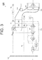
- FIG. 3 a schematic of an environmental control system 300 (e.g., an embodiment of the environmental control system 200) is depicted according to an embodiment. Components of the systems 100 and 200 that are similar to the environmental control system 300 have been reused for ease of explanation, by using the same identifiers, and are not re-introduced.
- Alternative components of the environmental control system 300 include a compressing device 310, which comprises a compressor 312, a turbine 313, a turbine 314, and a shaft 315, and a rotating device 316 (e.g., integral rotor or tip turbine), which comprises a turbine 317 and a fan 319, along with a secondary path for the medium sourced from the inlet 101 (e.g., a valve V3 can provide the medium from the inlet 101 to an inlet of the turbine 317).
- a compressing device 310 which comprises a compressor 312, a turbine 313, a turbine 314, and a shaft 315
- a rotating device 316 e.g., integral rotor or tip turbine
- a secondary path for the medium sourced from the inlet 101 e.g., a valve V3 can provide the medium from the inlet 101 to an inlet of the turbine 317.
- the environmental control system 300 operates similarly to the environmental control system 200 in that different mixing points are utilized based on the mode of operation.
- the environmental control system 300 separates the ram air fan (e.g., fan 116) from the air cycle machine (e.g., the compressing device 110) and provides the ram air fan within the rotating device 316.
- the turbine 317 of the rotating device 316 is powered by the bleed air sourced from the inlet 101 flowing through the valve V3.
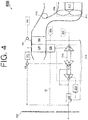
- FIG. 4 a schematic of an environmental control system 400 (e.g., an embodiment of the environmental control system 200) is depicted according to an embodiment.
- Components of the systems 100, 200, and 300 that are similar to the environmental control system 400 have been reused for ease of explanation, by using the same identifiers, and are not re-introduced.
- Alternative components of the environmental control system 400 include a rotating device 416, which comprises a motor 417 and a fan 419.
- the environmental control system 400 operates similarly to the environmental control system 200 in that different mixing points are utilized based on the mode of operation.
- the environmental control system 400 separates the ram air fan (e.g., fan 116) from the air cycle machine (e.g., the compressing device 110) and provides the ram air fan within the rotating device 416.
- the motor 417 of the rotating device 416 is powered by electric power.
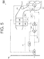
- FIG. 5 a schematic of an environmental control system 500 (e.g., an embodiment of the environmental control system 200) is depicted according to an embodiment.
- Components of the systems 100, 200, 300, and 400 that are similar to the environmental control system 500 have been reused for ease of explanation, by using the same identifiers, and are not re-introduced.
- Alternative components of the environmental control system 400 include a compressing device 510, which comprises a compressor 512, a turbine 513, and a shaft 515, and a rotating device 516, which comprises a turbine 517 and a fan 519. Note that the rotating device 516 is along a path of the medium sourced from the inlet 201, such that the rotating device 516 can be supplied this medium or bypassed.
- the environmental control system 500 operates similarly to the environmental control system 200 in that different mixing points are utilized based on the mode of operation.
- the environmental control system 500 separates the ram air fan (e.g., fan 116) from the air cycle machine (e.g., the compressing device 110) and provides the ram air fan within the rotating device 516.
- the turbine 517 of the rotating device 516 is powered by the fresh air sourced from the inlet 201.
- FIG. 6 a schematic of an environmental control system 600 (e.g., an embodiment of system 100), as it could be installed on an aircraft is depicted according to an embodiment.
- the environmental control system 600 can provide mixed air from any combination of fresh air, bleed air, and cabin discharge air.
- Components of the systems 100, 200, 300, 400 and 500 that are similar to the environmental control system 600 have been reused for ease of explanation, by using the same identifiers, and are not re-introduced.
- Alternative components of the environmental control system 600 include an outlet 601 and a compressing device 610 that comprises a compressor 612, a turbine 613, a turbine 614, a fan 616, and a shaft 618.
- Alternative components of the environmental control system 600 also include valves V6.1, V6.2, and V6.3.
- a path is further denoted by the dot-dashed line F6.1 for a flow the medium that is controlled by valve V6.1 to the outlet 601 (e.g., which can be overboard).
- Another path is denoted by the dot-dashed line F6.2 for a flow the medium that is controlled by valve V6.2 for supplying the cabin discharge air to the valve V6.3 (otherwise the cabin discharge air can be directed overboard through the shell 119).
- the turbine 614 can be a dual use and/or a dual entry turbine. A dual use turbine is configured to receive flows of different mediums in the alternative.
- a duel entry turbine is configured with multiple nozzles that can receive flows of mediums at different entry point, such that multiple flows can be received simultaneously.
- the turbine 614 can include a plurality of inlet gas flow paths, such as an inner flow path and an outer flow path, to enable mixing of alternative medium flows at the exit of the turbine 614.
- the inner flow path can be a first diameter
- the outer flow path can be a second diameter.
- the inner flow path can align with one of the first or second nozzles
- the outer flow path can align with the other of the first or second nozzles.
- the primary heat exchanger 120 cools the pressure high-temperature air to nearly ambient temperature to produce cool high pressure air.
- This cool high pressure air enters the condenser 160, where it is further cooled by air from the turbine 614 of the compressing device 610.
- the cool high pressure air Upon exiting the condenser 160, the cool high pressure air enters the water extractor 272 so that moisture in the air is removed.
- the cool high pressure air enters the turbine 613 through a nozzle.
- the cool high pressure air is expanded across the turbine 613 and work extracted from the cool high pressure air. This extracted work drives the compressor 612 used to compress fresh outside air. This extracted work also drives the fan 616, which is used to move air through the primary heat exchanger 120 and the secondary heat exchanger 130.
- the act of compressing the fresh outside air heats the fresh outside air.
- the compressed fresh outside air enters the outflow valve heat exchanger 230 and is cooled by the chamber discharge air to produce cooled compressed fresh outside air.
- the cooled compressed fresh outside air then enters the secondary heat exchanger 130 and is further cooled to nearly ambient temperature.
- the air exiting the secondary heat exchanger 130 then enters the water extractor 271, where any free moisture is removed, to produce cool medium pressure air.
- This cool medium pressure air then enters the turbine 614 through a nozzle.
- the cool medium pressure air is expanded across the turbine 614 and work extracted from the cool high pressure air.
- the two air flows (e.g., the fresh outside air sourcing from 201 and the bleed air sourcing from inlet 101) are mixed downstream of the turbine 613 to produce mixed air.
- a valve V6.1 can then be used to direct an outlet of the turbine 614 away from the chamber to the outlet 601 or to downstream of the turbine 613 (to provide the cool medium pressure air exiting the turbine 614 to the first mixing point such that it flows to the chamber 102).
- This downstream location can be considered a first mixing point of the environmental control system 600.
- the mixed air leaves then enters the condenser 160 to cool the bleed air leaving the primary heat exchanger 120.
- the mixed air is then sent to condition the chamber 102.
- This low altitude operation can be consider a low altitude mode.
- the low altitude mode can be used for ground and low altitude flight conditions, such as ground idle, taxi, take-off, and hold conditions.
- the fresh outside air can be mixed downstream of the condenser 160 (rather than at the first mixing point).
- the air exiting the water extractor 271 is the cool medium pressure air. This cool medium pressure air is directed by the valve V6.3 to downstream of the condenser 160.
- the valve V6.3 can also direct the cabin discharge air to the turbine 614.
- energy in the cabin discharge air can be used to power the compressor 612 by feeding (e.g., the dot-dashed line F6.2) the cabin discharge air to the turbine 614.
- the cabin discharge air enters the turbine 614 through a nozzle such that the turbine 614 extracts work from the hot air from the outflow valve heat exchanger 230.
- the cabin discharge air can continue overboard (e.g., to outlet 601) through valve V6.1. Overboard comprise an ambient pressure at high altitude operation.
- a pressure drop across the turbine 614 is created such that the cabin discharge air is drawn though the turbine 614 (e.g., cabin discharge air pressure is higher than ambient air pressure).
- the compressor 612 receives power from both the bleed air (across the turbine 613) and the cabin discharge air (across the turbine 614).
- This high altitude operation can be considered a high altitude mode.
- the high altitude mode can be used at high altitude cruise, climb, and descent flight conditions.
- fresh air aviation requirements for passengers are met by mixing the two air flows (e.g., the fresh outside air sourcing from 201 and the bleed air sourcing from inlet 101).
- an amount of bleed air needed can be reduced.
- the environmental control system 200 provides bleed air reduction ranging from 40% to 75% to provide higher efficiencies with respect to engine fuel burn than contemporary airplane air systems.
- FIGS. 7 , 8 , and 9 illustrate variations of the environmental control system 600.
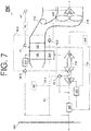
- FIG. 7 a schematic of an environmental control system 700 (e.g., an embodiment of the environmental control system 600) is depicted according to an embodiment.
- Components of the systems 100, 200, 300, 400, 500, and 600 that are similar to the environmental control system 700 have been reused for ease of explanation, by using the same identifiers, and are not re-introduced.
- Alternative components of the environmental control system 700 include a compressing device 710, which comprises a compressor 712, a turbine 713, a turbine 714, and a shaft 715. Note that the turbine 614 is both a dual use and a dual entry turbine.
- the environmental control system 700 operates similarly to the environmental control system 600 in that different mixing points are utilized based on the mode of operation.
- the environmental control system 700 separates the ram air fan (e.g., fan 116) from the air cycle machine (e.g., the compressing device 110) and provides the ram air fan within the rotating device 316.
- the turbine 317 of the rotating device 316 is powered by the bleed air sourced from the inlet 101 flowing through the valve V3.
- energy in the fresh air exiting from the water extractor 271 can be used to power the compressor 712 by feeding the air exiting the water extractor 271 via the valve V6.3 to the turbine 714.
- energy in the cabin discharge air exiting from the outflow valve heat exchanger 230 can be used to power the compressor 712 by feeding (e.g., the dot-dashed line F6.2) the cabin discharge air to the turbine 714.
- the additional or second turbine 714 can be fed air from the outflow valve heat exchanger 230 (e.g., cabin discharge air) and/or air exiting the water extractor 271 (e.g., fresh outside air), while the first turbine 713 can be fed air from the primary heat exchanger 120 (e.g., bleed air).
- the compressor 712 can receive power from the bleed air (via turbine 713), the cabin discharge air (via turbine 714), and/or the fresh outside air (also via turbine 714). Note that the cabin discharge air or the fresh outside air can be mixed with the bleed air downstream of the turbine 713.
- FIG. 8 a schematic of an environmental control system 800 (e.g., an embodiment of the environmental control system 600) is depicted according to an embodiment.
- Components of the systems 100, 200, 300, 400, 500, 600, and 700 that are similar to the environmental control system 800 have been reused for ease of explanation, by using the same identifiers, and are not re-introduced.
- the environmental control system 800 operates similarly to the environmental control system 600 in that different mixing points are utilized based on the mode of operation.
- the environmental control system 800 separates the ram air fan (e.g., fan 116) from the air cycle machine (e.g., the compressing device 710) and provides the ram air fan within the rotating device 416.
- the motor 417 of the rotating device 416 is powered by electric power.
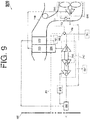
- FIG. 9 a schematic of an environmental control system 900 (e.g., an embodiment of the environmental control system 600) is depicted according to an embodiment.
- Components of the systems 100, 200, 300, 400, 500, 600, 700, and 800 that are similar to the environmental control system 900 have been reused for ease of explanation, by using the same identifiers, and are not re-introduced.
- Alternative components of the environmental control system 900 include a path for the medium denoted by the dot-dashed line F9 (where the medium can be provided from the chamber 102 to the turbine 714).
- the environmental control system 900 operates similarly to the environmental control system 600 in that different mixing points are utilized based on the mode of operation.
- the environmental control system 900 separates the ram air fan (e.g., fan 116) from the air cycle machine (e.g., the compressing device 110) and provides the ram air fan within the rotating device 516.
- the turbine 517 of the rotating device 516 is powered by the fresh air sourced from the inlet 201.
- the rotating device 516 is along a path of the medium sourced from the inlet 201, such that the rotating device 516 can be supplied this medium or bypassed based on the operation of valve V5.
- an exhaust from the turbine 714 can be sent to the outlet 202 (e.g., a cabin pressure control system) after the turbine 714 extracts work from the medium received from path F9.
Landscapes
- Health & Medical Sciences (AREA)
- General Health & Medical Sciences (AREA)
- Pulmonology (AREA)
- Engineering & Computer Science (AREA)
- Aviation & Aerospace Engineering (AREA)
- Structures Of Non-Positive Displacement Pumps (AREA)
Priority Applications (1)
| Application Number | Priority Date | Filing Date | Title |
|---|---|---|---|
| EP17204787.0A EP3492381A1 (de) | 2017-11-30 | 2017-11-30 | Mischen von zapf- und stauluft mittels einer zweiturbinenarchitektur mit einem ausflusswärmetauscher |
Applications Claiming Priority (1)
| Application Number | Priority Date | Filing Date | Title |
|---|---|---|---|
| EP17204787.0A EP3492381A1 (de) | 2017-11-30 | 2017-11-30 | Mischen von zapf- und stauluft mittels einer zweiturbinenarchitektur mit einem ausflusswärmetauscher |
Publications (1)
| Publication Number | Publication Date |
|---|---|
| EP3492381A1 true EP3492381A1 (de) | 2019-06-05 |
Family
ID=60569702
Family Applications (1)
| Application Number | Title | Priority Date | Filing Date |
|---|---|---|---|
| EP17204787.0A Withdrawn EP3492381A1 (de) | 2017-11-30 | 2017-11-30 | Mischen von zapf- und stauluft mittels einer zweiturbinenarchitektur mit einem ausflusswärmetauscher |
Country Status (1)
| Country | Link |
|---|---|
| EP (1) | EP3492381A1 (de) |
Citations (1)
| Publication number | Priority date | Publication date | Assignee | Title |
|---|---|---|---|---|
| CA2968745A1 (en) * | 2016-05-26 | 2017-11-26 | Hamilton Sundstrand Corporation | Mixing bleed and ram air using a two turbine architecture with an outflow heat exchanger |
-
2017
- 2017-11-30 EP EP17204787.0A patent/EP3492381A1/de not_active Withdrawn
Patent Citations (1)
| Publication number | Priority date | Publication date | Assignee | Title |
|---|---|---|---|---|
| CA2968745A1 (en) * | 2016-05-26 | 2017-11-26 | Hamilton Sundstrand Corporation | Mixing bleed and ram air using a two turbine architecture with an outflow heat exchanger |
Similar Documents
| Publication | Publication Date | Title |
|---|---|---|
| US10144517B2 (en) | Mixing bleed and ram air using a two turbine architecture with an outflow heat exchanger | |
| US10953992B2 (en) | Mixing bleed and ram air using an air cycle machine with two turbines | |
| US10604263B2 (en) | Mixing bleed and ram air using a dual use turbine system | |
| EP3248876B1 (de) | Mischen von zapf- und stau-luft an einem turbineneinlass einer komprimierungsvorrichtung | |
| US20210047044A1 (en) | Energy flow of an advanced environmental control system | |
| US10486817B2 (en) | Environmental control system with an outflow heat exchanger | |
| US10597162B2 (en) | Mixing bleed and ram air at a turbine inlet | |
| US10773807B2 (en) | Energy flow of an advanced environmental control system | |
| EP3248881B1 (de) | Mehrfachdüsenkonfigurationen für eine turbine eines klimaregelungssystems | |
| US11851190B2 (en) | Aircraft environmental control system | |
| EP3492381A1 (de) | Mischen von zapf- und stauluft mittels einer zweiturbinenarchitektur mit einem ausflusswärmetauscher |
Legal Events
| Date | Code | Title | Description |
|---|---|---|---|
| PUAI | Public reference made under article 153(3) epc to a published international application that has entered the european phase |
Free format text: ORIGINAL CODE: 0009012 |
|
| STAA | Information on the status of an ep patent application or granted ep patent |
Free format text: STATUS: THE APPLICATION HAS BEEN PUBLISHED |
|
| AK | Designated contracting states |
Kind code of ref document: A1 Designated state(s): AL AT BE BG CH CY CZ DE DK EE ES FI FR GB GR HR HU IE IS IT LI LT LU LV MC MK MT NL NO PL PT RO RS SE SI SK SM TR |
|
| AX | Request for extension of the european patent |
Extension state: BA ME |
|
| STAA | Information on the status of an ep patent application or granted ep patent |
Free format text: STATUS: REQUEST FOR EXAMINATION WAS MADE |
|
| 17P | Request for examination filed |
Effective date: 20191205 |
|
| RBV | Designated contracting states (corrected) |
Designated state(s): AL AT BE BG CH CY CZ DE DK EE ES FI FR GB GR HR HU IE IS IT LI LT LU LV MC MK MT NL NO PL PT RO RS SE SI SK SM TR |
|
| STAA | Information on the status of an ep patent application or granted ep patent |
Free format text: STATUS: EXAMINATION IS IN PROGRESS |
|
| 17Q | First examination report despatched |
Effective date: 20210506 |
|
| STAA | Information on the status of an ep patent application or granted ep patent |
Free format text: STATUS: EXAMINATION IS IN PROGRESS |
|
| STAA | Information on the status of an ep patent application or granted ep patent |
Free format text: STATUS: THE APPLICATION IS DEEMED TO BE WITHDRAWN |
|
| 18D | Application deemed to be withdrawn |
Effective date: 20211117 |