EP3492347A1 - Steering assistance device and steering assistance method - Google Patents
Steering assistance device and steering assistance method Download PDFInfo
- Publication number
- EP3492347A1 EP3492347A1 EP17834399.2A EP17834399A EP3492347A1 EP 3492347 A1 EP3492347 A1 EP 3492347A1 EP 17834399 A EP17834399 A EP 17834399A EP 3492347 A1 EP3492347 A1 EP 3492347A1
- Authority
- EP
- European Patent Office
- Prior art keywords
- steering
- vehicle
- unit
- force
- curvature
- Prior art date
- Legal status (The legal status is an assumption and is not a legal conclusion. Google has not performed a legal analysis and makes no representation as to the accuracy of the status listed.)
- Granted
Links
Images



Classifications
-
- B—PERFORMING OPERATIONS; TRANSPORTING
- B62—LAND VEHICLES FOR TRAVELLING OTHERWISE THAN ON RAILS
- B62D—MOTOR VEHICLES; TRAILERS
- B62D15/00—Steering not otherwise provided for
- B62D15/02—Steering position indicators ; Steering position determination; Steering aids
- B62D15/025—Active steering aids, e.g. helping the driver by actively influencing the steering system after environment evaluation
-
- B—PERFORMING OPERATIONS; TRANSPORTING
- B62—LAND VEHICLES FOR TRAVELLING OTHERWISE THAN ON RAILS
- B62D—MOTOR VEHICLES; TRAILERS
- B62D6/00—Arrangements for automatically controlling steering depending on driving conditions sensed and responded to, e.g. control circuits
- B62D6/008—Control of feed-back to the steering input member, e.g. simulating road feel in steer-by-wire applications
-
- B—PERFORMING OPERATIONS; TRANSPORTING
- B62—LAND VEHICLES FOR TRAVELLING OTHERWISE THAN ON RAILS
- B62D—MOTOR VEHICLES; TRAILERS
- B62D5/00—Power-assisted or power-driven steering
- B62D5/04—Power-assisted or power-driven steering electrical, e.g. using an electric servo-motor connected to, or forming part of, the steering gear
- B62D5/0457—Power-assisted or power-driven steering electrical, e.g. using an electric servo-motor connected to, or forming part of, the steering gear characterised by control features of the drive means as such
- B62D5/046—Controlling the motor
-
- B—PERFORMING OPERATIONS; TRANSPORTING
- B62—LAND VEHICLES FOR TRAVELLING OTHERWISE THAN ON RAILS
- B62D—MOTOR VEHICLES; TRAILERS
- B62D5/00—Power-assisted or power-driven steering
- B62D5/06—Power-assisted or power-driven steering fluid, i.e. using a pressurised fluid for most or all the force required for steering a vehicle
- B62D5/065—Power-assisted or power-driven steering fluid, i.e. using a pressurised fluid for most or all the force required for steering a vehicle characterised by specially adapted means for varying pressurised fluid supply based on need, e.g. on-demand, variable assist
-
- B—PERFORMING OPERATIONS; TRANSPORTING
- B62—LAND VEHICLES FOR TRAVELLING OTHERWISE THAN ON RAILS
- B62D—MOTOR VEHICLES; TRAILERS
- B62D5/00—Power-assisted or power-driven steering
- B62D5/06—Power-assisted or power-driven steering fluid, i.e. using a pressurised fluid for most or all the force required for steering a vehicle
- B62D5/09—Power-assisted or power-driven steering fluid, i.e. using a pressurised fluid for most or all the force required for steering a vehicle characterised by means for actuating valves
- B62D5/091—Hydraulic steer-by-wire systems, e.g. the valve being actuated by an electric motor
Definitions
- This disclosure relates to a steering assistance device and a steering assistance method, and in particular to a technique for assisting steering during curve traveling.
- Patent Literature 1 discloses a technique in which an assist pinion connected to a rack via a speed reducer is driven by a steering assistance force generated by a steering assistance motor which is a drive source.
- Patent Literature 1 JP-A-H11-198844
- a generation source of the steering assistance force is the motor alone.
- a hydraulic cylinder powered by an engine which is a generation source of steering assistance force in addition to the motor.
- This disclosure provides a technique for adjusting output of a motor and a power cylinder in a steering assistance device including the motor and the power cylinder powered by hydraulic pressure as generation sources of a steering assistance force.
- a steering assistance device includes: a curvature calculation unit, which calculates curvature of a lane on which a vehicle travels; an auxiliary unit, which includes: a first auxiliary unit that generates torque to assist steering of the vehicle by hydraulic pressure and a second auxiliary unit that generates torque to assist the steering of the vehicle by electric power; and a steering control unit, which causes the first auxiliary unit to generate torque with decreasing by a predetermined amount and causes the second auxiliary unit to generate torque equal to or less than the predetermined amount, in a case where the first auxiliary unit is capable of generating a steering assistance force such that a steering angle of the vehicle reaches a target steering angle determined according to the curvature so as to make the vehicle travel in the center of a lane.
- the steering assistance device may further include a speed measurement unit, which measures a travelling speed of the vehicle; and a steering-retention-force calculation unit, which calculates a steering retention force that is required to retain the target steering angle determined according to the curvature at the travelling speed measured by the speed measurement unit, wherein the steering control unit may cause the second auxiliary unit to generate torque in a direction canceling the steering retention force so as to minimize the steering retention force at the target steering angle.
- a steering assistance method includes: a step of detecting curvature of a lane on which a vehicle travels; a step of measuring a travelling speed of the vehicle; a step of calculating a steering retention force required for retaining a target steering angle determined according to the curvature at the measured travelling speed; a step of causing to reduce a steering assistance force based on hydraulic pressure; and a step of causing a motor to generate torque in a direction canceling the steering retention force so as to minimize the steering retention force at the target steering angle.
- a steering assistance device including a motor and a power cylinder powered by hydraulic pressure as generation sources of a steering assistance force
- the output of the motor and the power cylinder can be adjusted.
- FIG. 1 is a diagram for explaining an overview of a steering assistance device according to an embodiment.
- the steering assistance device according to the embodiment is mounted on a vehicle V and is used for assisting steering when the vehicle V travels on a curve.
- the steering assistance device according to the embodiment is suitably used for a large-sized vehicle V such as a bus or a truck.
- a large-sized vehicle V such as a bus or a truck.
- the vehicle V is a large-sized vehicle V such as a bus or a truck.
- torque is applied to a steering wheel 11 of the vehicle V in a direction in which the vehicle V goes straight, that is, in a direction in which a steering angle is 0 degree. Accordingly, in order to make the vehicle V travel on the curve, a driver applies a steering retention force that counteracts the torque to the steering wheel 11, and thus the vehicle V travels along the curve.
- the steering assistance device cooperates with a motor and a hydraulic cylinder mounted on the vehicle V to assist the steering of the vehicle V during the curve travel.
- the steering assistance device analyzes an image in front of the vehicle V captured by an imaging device 50 and calculates the curvature of the lane on which the vehicle V travels.
- the steering assistance device assists the steering of the vehicle V to reach a steering retention angle ⁇ of the steering wheel 11 to be retained for traveling along the lane of the vehicle V.
- the steering assistance device controls the steering such that the steering retention force is minimized at the steering retention angle ⁇ determined according to the curvature of the lane. Therefore, the driver of the vehicle V can sense the steering retention angle ⁇ to be maintained by the torque transmitted from the steering wheel 11, so that the vehicle V can naturally travel along the curve.
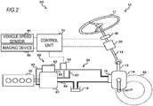
- FIG. 2 is a diagram schematically showing a configuration of a steering assistance system SS according to the embodiment.
- the steering assistance system SS includes an integral type steering unit 10, a motor 20, a steering angle sensor 30, a vehicle speed sensor 40, an imaging device 50, a pump unit 60, and a control unit 70.
- the integral type steering unit 10 is a unit for assisting a steering operation of a driver.
- the integral type steering unit 10 includes a steering wheel 11, a steering shaft 12, a stub shaft 13, a power cylinder unit 14, a reservoir tank 15, and a control valve 16.
- One end of the steering shaft 12 is connected to the steering wheel 11, and the other end is connected to the stub shaft 13.
- One end of the stub shaft 13 is connected to the steering shaft 12 and the other end is connected to an input shaft of the power cylinder unit 14.
- the steering shaft 12 and the stub shaft 13 transmit the steering torque applied to the steering wheel 11 to the power cylinder unit 14.
- the power cylinder unit 14 transmits a driving force to a steered wheel 80 of the vehicle V.
- the reservoir tank 15 stores hydraulic oil to be supplied to the power cylinder unit 14.
- the control valve 16 controls an oil amount of the hydraulic oil to be supplied to the power cylinder unit 14 and applies the hydraulic pressure corresponding to the steering torque to the internal of the power cylinder unit 14 to assist the steering operation of the driver.
- the motor 20 is attached to the steering shaft 12.
- the motor 20 is rotationally driven by electric power supplied from the control unit 70, and thus assistance torque (steering assistance force) is applied to the steering shaft 12 to assist the steering operation of the driver.
- the motor 20 mainly provides a steering induction function to make the vehicle V travel along the traveling lane.
- the steering angle sensor 30 is provided on the steering shaft 12, detects a rotation amount of the steering shaft 12, and detects a steering angle based on the rotation amount.
- the steering angle sensor 30 outputs the detected steering angle to the control unit 70.
- the vehicle speed sensor 40 detects a speed of the vehicle V.
- the vehicle speed sensor 40 outputs the detected speed to the control unit 70.
- the imaging device 50 is an in-vehicle camera mounted on the vehicle V.
- the imaging device 50 captures the front of the traveling direction of the vehicle V, the front including the lane on which the vehicle V travels.
- the imaging device 50 outputs the captured image to the control unit 70.
- the pump unit 60 is a known variable displacement pump.
- the pump unit 60 controls a flow rate of driving oil supplied to the power cylinder unit 14 based on the movement of the steering wheel 11 under the control of the control unit 70, so as to provide a power assistance function for further transmitting a force, which is in the same direction as the steering force transmitted to the power cylinder unit 14, to the power cylinder unit 14.
- the pump unit 60 includes a pump housing 61, a control valve 62, and a electromagnetic valve 63.
- the pump housing 61 defines and forms a pump chamber therein.
- the pump chamber is connected to the reservoir tank 15 via a suction passage 64 and sucks the hydraulic oil from the reservoir tank 15 via the suction passage 64.
- the pump chamber is connected to a first connection passage 65 through which the hydraulic oil is supplied to the control valve 62 and is connected to a second connection passage 66 through which the hydraulic oil is supplied to the control valve 16.
- the second connection passage 66 includes a main oil passage 67 connected to the control valve 16 and an auxiliary oil passage 68 that can be opened and closed and is connected to the control valve 62.
- the control valve 62 cooperates with the electromagnetic valve 63 to control the flow rate of the hydraulic oil to be supplied to the power cylinder unit 14.
- the electromagnetic valve 63 controls the opening and closing of the auxiliary oil passage 68.
- the electromagnetic valve 63 performs control such that electric power is supplied based on the steering angle detected by the steering angle sensor 30 and the traveling speed of the vehicle V detected by the vehicle speed sensor 40 that are from the control unit 70.
- an amount of electricity supplied to the electromagnetic valve 63 increases as the steering angle increases. Since the steering assistance force is required as the speed of the vehicle V decreases, the amount of electricity supplied to the electromagnetic valve 63 increases as the traveling speed of the vehicle V decreases.
- the electromagnetic valve 63 closes the auxiliary oil passage 68 in a non-energized state.
- the control valve 62 decreases a pump discharge amount in the pump unit 60.
- the electromagnetic valve 63 opens the auxiliary oil passage 68 in an energized state.
- the control valve 62 increases the pump discharge amount in the pump unit 60.
- the imaging device 50 is an in-vehicle camera mounted on the vehicle V.
- the imaging device 50 captures an image in front of the vehicle V in the traveling direction and the image including the lane on which the vehicle V travels.
- the control unit 70 analyzes the image captured by the imaging device 50 and calculates curvature of the lane on which the vehicle V travels.
- the control unit 70 calculates a target steering angle necessary for the vehicle V to travel on the lane based on the calculated curvature.
- the control unit 70 realizes support of keeping the vehicle V on the lane by controlling the power cylinder unit 14 and the motor 20 based on the calculated target steering angle.
- the steering assistance device 1 functions as power assistance and support of keeping the vehicle V on the lane, but the functional configuration of the steering assistance device 1 for realizing the support function of keeping the vehicle V on the lane will be mainly described below.
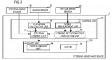
- FIG. 3 is a diagram schematically showing a functional configuration of the steering assistance device 1 according to the embodiment.
- the steering assistance device 1 includes a control unit 70 and an auxiliary unit 100.
- the control unit 70 is a calculation resource including a CPU (Central Processing Unit), a memory or the like (not shown) and realizes functions of a curvature calculation unit 71, a speed measurement unit 72, a steering-retention-force calculation unit 73, and a steering control unit 74 by executing a program.
- CPU Central Processing Unit
- the control unit 70 is a calculation resource including a CPU (Central Processing Unit), a memory or the like (not shown) and realizes functions of a curvature calculation unit 71, a speed measurement unit 72, a steering-retention-force calculation unit 73, and a steering control unit 74 by executing a program.
- the auxiliary unit 100 is a mechanism that assists the driver of the vehicle V to move the steered wheel 80 by operating the steering wheel 11, and includes the motor 20 and the power cylinder unit 14.
- the power cylinder unit 14 functions as a first auxiliary unit for generating, by hydraulic pressure, torque for assisting the steering of the vehicle V.
- the motor 20 functions as a second auxiliary unit for generating, by electric power, torque for assisting steering of the vehicle V.
- the curvature calculation unit 71 acquires the image captured by the imaging device 50.
- the curvature calculation unit 71 calculates the curvature of the lane on which the vehicle V travels by analyzing the acquired image. Specifically, the curvature calculation unit 71 calculates the curvature of the lane by extracting a lane defining line of the lane on which the vehicle V travels using a known image processing technique such as edge extraction.
- the speed measurement unit 72 measures a travelling speed of the vehicle V using the vehicle speed sensor.
- the steering-retention-force calculation unit 73 calculates a target steering angle determined according to the curvature calculated by the curvature calculation unit 71.
- the steering-retention-force calculation unit 73 further calculates a steering retention force required for retaining the calculated target steering angle at the traveling speed measured by the speed measurement unit 72.
- the steering control unit 74 causes the motor 20 to generate a steering assistance force in a direction canceling the steering retention force so as to minimize the steering retention force to be applied to the driver of the vehicle V at the target steering angle calculated by the steering-retention-force calculation unit 73.
- the steering control unit 74 causes the motor 20 to generate torque in the direction cancelling the steering retention force even when the power cylinder unit 14 can independently generate the steering assistance force. More specifically, the steering control unit 74 reduces the torque generated by the power cylinder unit 14 during straight traveling of the vehicle V by a predetermined amount and causes the motor 20 to generate torque equal to or less than the decreased predetermined amount.
- FIGS. 4A to 4D are diagrams for explaining torque control of the auxiliary unit 100 executed by the steering control unit 74 according to the embodiment.
- FIGS. 4A, 4B and 4D are diagrams showing the relationship between the steering angle and the torque, wherein a horizontal axis represents the steering angle of the steering wheel 11 and the vertical axis represents the magnitude of the torque which is a resistance force felt by the driver who operates the steering wheel 11.
- FIG. 4C is a diagram showing the relationship between the steering angle and the torque, wherein the horizontal axis represents the steering angle of the steering wheel 11 and the vertical axis represents the torque generated by the motor 20 under the control of the steering control unit 74.
- the steering angle is a negative value when the driver of the vehicle V turns the steering wheel 11 to the left, and the steering angle is a positive value when steering wheel 11 is turned to the right.
- the magnitude of the torque that is a resistance force felt by the driver who operates the steering wheel 11 may be referred to as “steering retention torque”
- the magnitude of the torque generated by the power cylinder unit 14 or the motor 20 under the control of the steering control unit 74 may be referred to as "steering assistance force”.
- FIG. 4A is a diagram showing the relationship between the steering angle and the steering retention torque during straight traveling of the vehicle V equipped with the steering assistance device 1 according to the embodiment.
- the steering control unit 74 stops the output of the steering assistance force generated by the motor 20 and outputs only the steering assistance force generated by the power cylinder unit 14.
- the diagrams showing the relationship between the steering angle and the steering retention torque is substantially U-shaped.
- an angle ⁇ indicates the target steering angle calculated by the steering-retention-force calculation unit 73. That is, it indicates that it is necessary for the driver to keep the steering wheel 11 turned to the right by an angle ⁇ in order to make the vehicle V travel along the lane.
- the steering control unit 74 controls the output of the power cylinder unit 14 and the motor 20 so as to minimize the steering retention torque at the angle ⁇ . Specifically, the steering control unit 74 first lowers the output of the power cylinder unit 14 as a whole by a predetermined amount t. As a result, a shape of the diagram showing the relationship between the steering angle and the steering retention torque is as shown in FIG. 4B . Assuming that the steering wheel 11 is operated in a state where the characteristic of the steering retention torque is as shown in FIG. 4B , the driver of the vehicle V feels that the steering wheel 11 as a whole becomes heavier by the torque represented by the predetermined amount t.
- the steering control unit 74 lowers the output of the power cylinder unit 14 by the predetermined amount t and at the same time causes the motor 20 to output torque whose maximum value is equal to or less than the predetermined amount t.
- FIG. 4C is a diagram showing the relationship between the steering assistance force output by the motor 20 under the control of the steering control unit 74 and the steering angle.
- the steering control unit 74 causes the motor 20 to output the steering assistance force directed in the same direction as the steering direction of the steering wheel 11 so as to maximize the steering angle when the steering angle is the angle ⁇ .
- the steering control unit 74 decreases the torque output by the motor 20 as the degree of deviation increases.
- FIG. 4D is a diagram showing characteristics of the steering retention torque in a case where the steering control unit 74 lowers the output of the power cylinder unit 14 by the predetermined amount t and causes the motor 20 to output the torque according to the steering angle of the steering wheel 11.
- the steering control unit 74 lowers the output of the power cylinder unit 14 by the predetermined amount t and causes the motor 20 to output the torque according to the steering angle of the steering wheel 11.
- the steering retention force increases as the steering angle of the steering wheel 11 deviates from the angle ⁇ which is the target steering angle.
- the steering control unit 74 controls the output of the power cylinder unit 14 and the motor 20 such that the steering angle of the steering wheel 11 is a so-called valley at the angle ⁇ . Then, the steering control unit 74 determines the shape of torque to be generated by the motor 20 in consideration of the torque characteristic of the power cylinder unit 14 in the vicinity of the angle ⁇ . As a result, since the steering angle of the steering wheel 11 can be set to the so-called valley at the angle ⁇ , the driver of the vehicle V can sense the resistance of transmitting the steering angle of the steering wheel 11 to the hand, in order to make the vehicle V travel along the lane.
- the steering control unit 74 controls the power cylinder unit 14 and the motor 20 such that the steering retention force is minimized when the steering angle of the steering wheel 11 is the angle ⁇ which is the target steering angle
- the minimum value of the steering retention force is greater than 0.
- the driver of the vehicle V needs to intentionally apply a force to the steering wheel 11. Accordingly, it is possible to suppress a situation in which the driver drives the vehicle V unthinkingly.
- the "predetermined amount t" which is the amount by which the steering control unit 74 lowers the output of the power cylinder unit 14, is preferably equal to or less than the maximum value of the torque that the motor 20 can output. Accordingly, the steering control unit 74 can arbitrarily set the minimum value of the steering retention force between 0 and the predetermined amount t.
- FIG. 5 is a flow chart for explaining a flow of a steering assistance process executed by the steering assistance device 1 according to the embodiment. The process in this flow chart starts, for example, when the engine of the vehicle V is started.
- the curvature calculation unit 71 analyzes an image captured by the imaging device 50 and detects curvature of a lane on which the vehicle V travels (S2).
- the steering-retention-force calculation unit 73 calculates (S4) a target steering angle determined according to the curvature calculated by the curvature calculation unit 71.
- the speed measurement unit 72 detects (S6) a vehicle speed of the vehicle V using the vehicle speed sensor.
- the steering-retention-force calculation unit 73 calculates (S8) a steering retention force required to retain a target steering angle calculated at the traveling speed measured by the speed measurement unit 72.
- the steering control unit 74 decreases the steering assistance force generated by the power cylinder unit 14 by a predetermined amount, and increases the steering assistance force generated by the motor 20 when the vehicle V travels straight (S10).
- the steering assistance device 1 continues controlling the steering assistance force during traveling of the vehicle V by repeating the above process during traveling of the vehicle V.
- the output of the power cylinder unit 14 and the motor 20 can be adjusted in the steering assistance device 1 including the power cylinder unit 14 and the motor 20 as sources of the steering assistance force.
- the steering control unit 74 does not cause the power cylinder unit 14 to generate the steering assistance force all by itself, even in a case where the power cylinder unit 14 can generate a steering assistance force all by itself such that the steering angle of the vehicle V can reach the target steering angle determined according to the curvature of the lane.
- the steering control unit 74 reduces the steering assistance force generated by the power cylinder unit 14 and supplements the steering assistance force corresponding to the reduced steering assistance force with the output of the motor 20.
- the motor 20 can generate torque larger than that of the power cylinder unit 14 while the power cylinder unit 14 can more finely adjust the generated torque than the motor 20. Therefore, since the steering control unit 74 compensates the reduction in the steering assistance force of the power cylinder unit 14 with the steering assistance force of the motor 20, the relationship between the steering angle and the steering retention torque can be finely adjusted.
- the steering assistance force is generated in the power cylinder unit 14. Accordingly, the driver of the vehicle V can sense the resistance of transmitting the steering angle of the steering wheel 11 to the hand in order to make the vehicle V travel along the lane.
Landscapes
- Engineering & Computer Science (AREA)
- Chemical & Material Sciences (AREA)
- Combustion & Propulsion (AREA)
- Transportation (AREA)
- Mechanical Engineering (AREA)
- Steering Control In Accordance With Driving Conditions (AREA)
- Control Of Driving Devices And Active Controlling Of Vehicle (AREA)
Description
- This disclosure relates to a steering assistance device and a steering assistance method, and in particular to a technique for assisting steering during curve traveling.
- A steering force control device has been proposed in which a neutral value of steering torque is changed according to curvature of the road so as to appropriately facilitate steering of a driver. For example, Patent Literature 1 discloses a technique in which an assist pinion connected to a rack via a speed reducer is driven by a steering assistance force generated by a steering assistance motor which is a drive source.
- Patent Literature 1:
JP-A-H11-198844 - In the above technique, a generation source of the steering assistance force is the motor alone. However, in a large-sized vehicle such as a bus or a truck, there is also a hydraulic cylinder powered by an engine which is a generation source of steering assistance force in addition to the motor.
- There is a difference in output characteristics between the motor and the hydraulic cylinder as generation sources of the steering assistance force. Therefore, in a steering assistance device provided with both a motor and a hydraulic cylinder as generation sources of the steering assistance force, a technique for adjusting the output of the motor and the hydraulic cylinder is desired.
- This disclosure provides a technique for adjusting output of a motor and a power cylinder in a steering assistance device including the motor and the power cylinder powered by hydraulic pressure as generation sources of a steering assistance force.
- A steering assistance device according to a first aspect of this disclosure includes: a curvature calculation unit, which calculates curvature of a lane on which a vehicle travels; an auxiliary unit, which includes: a first auxiliary unit that generates torque to assist steering of the vehicle by hydraulic pressure and a second auxiliary unit that generates torque to assist the steering of the vehicle by electric power; and a steering control unit, which causes the first auxiliary unit to generate torque with decreasing by a predetermined amount and causes the second auxiliary unit to generate torque equal to or less than the predetermined amount, in a case where the first auxiliary unit is capable of generating a steering assistance force such that a steering angle of the vehicle reaches a target steering angle determined according to the curvature so as to make the vehicle travel in the center of a lane.
- The steering assistance device may further include a speed measurement unit, which measures a travelling speed of the vehicle; and a steering-retention-force calculation unit, which calculates a steering retention force that is required to retain the target steering angle determined according to the curvature at the travelling speed measured by the speed measurement unit, wherein the steering control unit may cause the second auxiliary unit to generate torque in a direction canceling the steering retention force so as to minimize the steering retention force at the target steering angle.
- A steering assistance method according to a second aspect of this disclosure includes: a step of detecting curvature of a lane on which a vehicle travels; a step of measuring a travelling speed of the vehicle; a step of calculating a steering retention force required for retaining a target steering angle determined according to the curvature at the measured travelling speed; a step of causing to reduce a steering assistance force based on hydraulic pressure; and a step of causing a motor to generate torque in a direction canceling the steering retention force so as to minimize the steering retention force at the target steering angle.
- According to this disclosure, in a steering assistance device including a motor and a power cylinder powered by hydraulic pressure as generation sources of a steering assistance force, the output of the motor and the power cylinder can be adjusted.
-
-
FIG. 1 is a diagram for explaining an overview of a steering assistance device according to an embodiment. -
FIG. 2 is a diagram schematically showing a configuration of a steering assistance system according to the embodiment. -
FIG. 3 is a diagram schematically showing a functional configuration of the steering assistance device according to the embodiment. -
FIGS. 4A to 4D are diagrams for explaining torque control of an auxiliary unit executed by a steering control unit according to the embodiment. -
FIG. 5 is a flow chart for explaining a flow of a steering assistance process executed by the steering assistance device according to the embodiment. -
FIG. 1 is a diagram for explaining an overview of a steering assistance device according to an embodiment. The steering assistance device according to the embodiment is mounted on a vehicle V and is used for assisting steering when the vehicle V travels on a curve. Although not limited, the steering assistance device according to the embodiment is suitably used for a large-sized vehicle V such as a bus or a truck. In the following specification, it is assumed that the vehicle V is a large-sized vehicle V such as a bus or a truck. - In general, torque is applied to a
steering wheel 11 of the vehicle V in a direction in which the vehicle V goes straight, that is, in a direction in which a steering angle is 0 degree. Accordingly, in order to make the vehicle V travel on the curve, a driver applies a steering retention force that counteracts the torque to thesteering wheel 11, and thus the vehicle V travels along the curve. The steering assistance device according to the embodiment cooperates with a motor and a hydraulic cylinder mounted on the vehicle V to assist the steering of the vehicle V during the curve travel. - Specifically, the steering assistance device analyzes an image in front of the vehicle V captured by an
imaging device 50 and calculates the curvature of the lane on which the vehicle V travels. The steering assistance device assists the steering of the vehicle V to reach a steering retention angle θ of thesteering wheel 11 to be retained for traveling along the lane of the vehicle V. - That is, although a steering retention force which is the torque required to maintain an angle of the
steering wheel 11 of the vehicle V is generally changed according to a steering angle, the steering assistance device controls the steering such that the steering retention force is minimized at the steering retention angle θ determined according to the curvature of the lane. Therefore, the driver of the vehicle V can sense the steering retention angle θ to be maintained by the torque transmitted from thesteering wheel 11, so that the vehicle V can naturally travel along the curve. -
FIG. 2 is a diagram schematically showing a configuration of a steering assistance system SS according to the embodiment. As shown inFIG. 2 , the steering assistance system SS includes an integraltype steering unit 10, amotor 20, asteering angle sensor 30, avehicle speed sensor 40, animaging device 50, apump unit 60, and acontrol unit 70. - The integral
type steering unit 10 is a unit for assisting a steering operation of a driver. The integraltype steering unit 10 includes asteering wheel 11, asteering shaft 12, astub shaft 13, apower cylinder unit 14, areservoir tank 15, and acontrol valve 16. - One end of the
steering shaft 12 is connected to thesteering wheel 11, and the other end is connected to thestub shaft 13. One end of thestub shaft 13 is connected to thesteering shaft 12 and the other end is connected to an input shaft of thepower cylinder unit 14. Thesteering shaft 12 and thestub shaft 13 transmit the steering torque applied to thesteering wheel 11 to thepower cylinder unit 14. - The
power cylinder unit 14 transmits a driving force to a steeredwheel 80 of the vehicle V. - The
reservoir tank 15 stores hydraulic oil to be supplied to thepower cylinder unit 14. - The
control valve 16 controls an oil amount of the hydraulic oil to be supplied to thepower cylinder unit 14 and applies the hydraulic pressure corresponding to the steering torque to the internal of thepower cylinder unit 14 to assist the steering operation of the driver. - The
motor 20 is attached to thesteering shaft 12. Themotor 20 is rotationally driven by electric power supplied from thecontrol unit 70, and thus assistance torque (steering assistance force) is applied to thesteering shaft 12 to assist the steering operation of the driver. Themotor 20 mainly provides a steering induction function to make the vehicle V travel along the traveling lane. - The
steering angle sensor 30 is provided on thesteering shaft 12, detects a rotation amount of thesteering shaft 12, and detects a steering angle based on the rotation amount. Thesteering angle sensor 30 outputs the detected steering angle to thecontrol unit 70. - The
vehicle speed sensor 40 detects a speed of the vehicle V. Thevehicle speed sensor 40 outputs the detected speed to thecontrol unit 70. - The
imaging device 50 is an in-vehicle camera mounted on the vehicle V. Theimaging device 50 captures the front of the traveling direction of the vehicle V, the front including the lane on which the vehicle V travels. Theimaging device 50 outputs the captured image to thecontrol unit 70. - The
pump unit 60 is a known variable displacement pump. Thepump unit 60 controls a flow rate of driving oil supplied to thepower cylinder unit 14 based on the movement of thesteering wheel 11 under the control of thecontrol unit 70, so as to provide a power assistance function for further transmitting a force, which is in the same direction as the steering force transmitted to thepower cylinder unit 14, to thepower cylinder unit 14. - The
pump unit 60 includes apump housing 61, acontrol valve 62, and aelectromagnetic valve 63. - The
pump housing 61 defines and forms a pump chamber therein. The pump chamber is connected to thereservoir tank 15 via asuction passage 64 and sucks the hydraulic oil from thereservoir tank 15 via thesuction passage 64. The pump chamber is connected to afirst connection passage 65 through which the hydraulic oil is supplied to thecontrol valve 62 and is connected to asecond connection passage 66 through which the hydraulic oil is supplied to thecontrol valve 16. - The
second connection passage 66 includes amain oil passage 67 connected to thecontrol valve 16 and anauxiliary oil passage 68 that can be opened and closed and is connected to thecontrol valve 62. - The
control valve 62 cooperates with theelectromagnetic valve 63 to control the flow rate of the hydraulic oil to be supplied to thepower cylinder unit 14. - The
electromagnetic valve 63 controls the opening and closing of theauxiliary oil passage 68. Theelectromagnetic valve 63 performs control such that electric power is supplied based on the steering angle detected by thesteering angle sensor 30 and the traveling speed of the vehicle V detected by thevehicle speed sensor 40 that are from thecontrol unit 70. - For example, since the steering assistance force is required as the steering angle increases, an amount of electricity supplied to the
electromagnetic valve 63 increases as the steering angle increases. Since the steering assistance force is required as the speed of the vehicle V decreases, the amount of electricity supplied to theelectromagnetic valve 63 increases as the traveling speed of the vehicle V decreases. - The
electromagnetic valve 63 closes theauxiliary oil passage 68 in a non-energized state. When theauxiliary oil passage 68 is closed, thecontrol valve 62 decreases a pump discharge amount in thepump unit 60. Meanwhile, theelectromagnetic valve 63 opens theauxiliary oil passage 68 in an energized state. When theauxiliary oil passage 68 is opened, thecontrol valve 62 increases the pump discharge amount in thepump unit 60. - The
imaging device 50 is an in-vehicle camera mounted on the vehicle V. Theimaging device 50 captures an image in front of the vehicle V in the traveling direction and the image including the lane on which the vehicle V travels. Thecontrol unit 70 analyzes the image captured by theimaging device 50 and calculates curvature of the lane on which the vehicle V travels. Thecontrol unit 70 calculates a target steering angle necessary for the vehicle V to travel on the lane based on the calculated curvature. Thecontrol unit 70 realizes support of keeping the vehicle V on the lane by controlling thepower cylinder unit 14 and themotor 20 based on the calculated target steering angle. - As described above, the steering assistance device 1 according to the embodiment functions as power assistance and support of keeping the vehicle V on the lane, but the functional configuration of the steering assistance device 1 for realizing the support function of keeping the vehicle V on the lane will be mainly described below.
-
FIG. 3 is a diagram schematically showing a functional configuration of the steering assistance device 1 according to the embodiment. - The steering assistance device 1 includes a
control unit 70 and anauxiliary unit 100. Thecontrol unit 70 is a calculation resource including a CPU (Central Processing Unit), a memory or the like (not shown) and realizes functions of acurvature calculation unit 71, aspeed measurement unit 72, a steering-retention-force calculation unit 73, and asteering control unit 74 by executing a program. - The
auxiliary unit 100 is a mechanism that assists the driver of the vehicle V to move the steeredwheel 80 by operating thesteering wheel 11, and includes themotor 20 and thepower cylinder unit 14. Thepower cylinder unit 14 functions as a first auxiliary unit for generating, by hydraulic pressure, torque for assisting the steering of the vehicle V. Themotor 20 functions as a second auxiliary unit for generating, by electric power, torque for assisting steering of the vehicle V. - The
curvature calculation unit 71 acquires the image captured by theimaging device 50. Thecurvature calculation unit 71 calculates the curvature of the lane on which the vehicle V travels by analyzing the acquired image. Specifically, thecurvature calculation unit 71 calculates the curvature of the lane by extracting a lane defining line of the lane on which the vehicle V travels using a known image processing technique such as edge extraction. - The
speed measurement unit 72 measures a travelling speed of the vehicle V using the vehicle speed sensor. The steering-retention-force calculation unit 73 calculates a target steering angle determined according to the curvature calculated by thecurvature calculation unit 71. The steering-retention-force calculation unit 73 further calculates a steering retention force required for retaining the calculated target steering angle at the traveling speed measured by thespeed measurement unit 72. - The
steering control unit 74 causes themotor 20 to generate a steering assistance force in a direction canceling the steering retention force so as to minimize the steering retention force to be applied to the driver of the vehicle V at the target steering angle calculated by the steering-retention-force calculation unit 73. Here, thesteering control unit 74 causes themotor 20 to generate torque in the direction cancelling the steering retention force even when thepower cylinder unit 14 can independently generate the steering assistance force. More specifically, thesteering control unit 74 reduces the torque generated by thepower cylinder unit 14 during straight traveling of the vehicle V by a predetermined amount and causes themotor 20 to generate torque equal to or less than the decreased predetermined amount. -
FIGS. 4A to 4D are diagrams for explaining torque control of theauxiliary unit 100 executed by thesteering control unit 74 according to the embodiment.FIGS. 4A, 4B and 4D are diagrams showing the relationship between the steering angle and the torque, wherein a horizontal axis represents the steering angle of thesteering wheel 11 and the vertical axis represents the magnitude of the torque which is a resistance force felt by the driver who operates thesteering wheel 11.FIG. 4C is a diagram showing the relationship between the steering angle and the torque, wherein the horizontal axis represents the steering angle of thesteering wheel 11 and the vertical axis represents the torque generated by themotor 20 under the control of thesteering control unit 74. - In
FIGS. 4A to 4D , the steering angle is a negative value when the driver of the vehicle V turns thesteering wheel 11 to the left, and the steering angle is a positive value when steeringwheel 11 is turned to the right. For convenience of explanation below, the magnitude of the torque that is a resistance force felt by the driver who operates thesteering wheel 11 may be referred to as "steering retention torque", and the magnitude of the torque generated by thepower cylinder unit 14 or themotor 20 under the control of thesteering control unit 74 may be referred to as "steering assistance force". -
FIG. 4A is a diagram showing the relationship between the steering angle and the steering retention torque during straight traveling of the vehicle V equipped with the steering assistance device 1 according to the embodiment. When the vehicle V travels straight ahead, thesteering control unit 74 stops the output of the steering assistance force generated by themotor 20 and outputs only the steering assistance force generated by thepower cylinder unit 14. - As shown in
FIGS. 4A to 4D , in a case where the steering assistance is realized only by the steering assistance force generated by thepower cylinder unit 14, the change in steering retention torque tends to decrease when the steering angle is around 0 degree. Therefore, the diagrams showing the relationship between the steering angle and the steering retention torque is substantially U-shaped. - In
FIGS. 4A to 4D , an angle θ indicates the target steering angle calculated by the steering-retention-force calculation unit 73. That is, it indicates that it is necessary for the driver to keep thesteering wheel 11 turned to the right by an angle θ in order to make the vehicle V travel along the lane. - In a case where only the steering assistance force generated by the
power cylinder unit 14 is output as shown inFIG. 4A , that is, in a case where theauxiliary unit 100 realizes only the power assist function, as the driver tries to turn thesteering wheel 11 further to the right side than the angle θ, the steering retention torque increases, and conversely, as the angle is smaller than the angle θ, the steering retention torque decreases. That is, the force acts on thesteering wheel 11 in a direction in which the steering angle decreases. - Therefore, the
steering control unit 74 controls the output of thepower cylinder unit 14 and themotor 20 so as to minimize the steering retention torque at the angle θ. Specifically, thesteering control unit 74 first lowers the output of thepower cylinder unit 14 as a whole by a predetermined amount t. As a result, a shape of the diagram showing the relationship between the steering angle and the steering retention torque is as shown inFIG. 4B . Assuming that thesteering wheel 11 is operated in a state where the characteristic of the steering retention torque is as shown inFIG. 4B , the driver of the vehicle V feels that thesteering wheel 11 as a whole becomes heavier by the torque represented by the predetermined amount t. - The
steering control unit 74 lowers the output of thepower cylinder unit 14 by the predetermined amount t and at the same time causes themotor 20 to output torque whose maximum value is equal to or less than the predetermined amount t. -
FIG. 4C is a diagram showing the relationship between the steering assistance force output by themotor 20 under the control of thesteering control unit 74 and the steering angle. As shown inFIG. 4C , thesteering control unit 74 causes themotor 20 to output the steering assistance force directed in the same direction as the steering direction of thesteering wheel 11 so as to maximize the steering angle when the steering angle is the angle θ. When the steering angle deviates from the angle θ, thesteering control unit 74 decreases the torque output by themotor 20 as the degree of deviation increases. -
FIG. 4D is a diagram showing characteristics of the steering retention torque in a case where thesteering control unit 74 lowers the output of thepower cylinder unit 14 by the predetermined amount t and causes themotor 20 to output the torque according to the steering angle of thesteering wheel 11. As shown inFIG. 4D , when the steering angle of thesteering wheel 11 is the angle θ which is the target steering angle, the steering retention force is minimized. In addition, the steering retention force increases as the steering angle of thesteering wheel 11 deviates from the angle θ which is the target steering angle. - Accordingly, the
steering control unit 74 controls the output of thepower cylinder unit 14 and themotor 20 such that the steering angle of thesteering wheel 11 is a so-called valley at the angle θ. Then, thesteering control unit 74 determines the shape of torque to be generated by themotor 20 in consideration of the torque characteristic of thepower cylinder unit 14 in the vicinity of the angle θ. As a result, since the steering angle of thesteering wheel 11 can be set to the so-called valley at the angle θ, the driver of the vehicle V can sense the resistance of transmitting the steering angle of thesteering wheel 11 to the hand, in order to make the vehicle V travel along the lane. - As shown in
FIGS. 4A to 4D , although thesteering control unit 74 controls thepower cylinder unit 14 and themotor 20 such that the steering retention force is minimized when the steering angle of thesteering wheel 11 is the angle θ which is the target steering angle, it is preferable that the minimum value of the steering retention force is greater than 0. In this case, in order to drive the vehicle V along the lane, the driver of the vehicle V needs to intentionally apply a force to thesteering wheel 11. Accordingly, it is possible to suppress a situation in which the driver drives the vehicle V unthinkingly. - Therefore, the "predetermined amount t", which is the amount by which the
steering control unit 74 lowers the output of thepower cylinder unit 14, is preferably equal to or less than the maximum value of the torque that themotor 20 can output. Accordingly, thesteering control unit 74 can arbitrarily set the minimum value of the steering retention force between 0 and the predetermined amount t. -
FIG. 5 is a flow chart for explaining a flow of a steering assistance process executed by the steering assistance device 1 according to the embodiment. The process in this flow chart starts, for example, when the engine of the vehicle V is started. - The
curvature calculation unit 71 analyzes an image captured by theimaging device 50 and detects curvature of a lane on which the vehicle V travels (S2). The steering-retention-force calculation unit 73 calculates (S4) a target steering angle determined according to the curvature calculated by thecurvature calculation unit 71. - The
speed measurement unit 72 detects (S6) a vehicle speed of the vehicle V using the vehicle speed sensor. The steering-retention-force calculation unit 73 calculates (S8) a steering retention force required to retain a target steering angle calculated at the traveling speed measured by thespeed measurement unit 72. - The
steering control unit 74 decreases the steering assistance force generated by thepower cylinder unit 14 by a predetermined amount, and increases the steering assistance force generated by themotor 20 when the vehicle V travels straight (S10). - When the
steering control unit 74 controls the steering assistance force generated by thepower cylinder unit 14 and themotor 20, the process in this flow chart ends. The steering assistance device 1 continues controlling the steering assistance force during traveling of the vehicle V by repeating the above process during traveling of the vehicle V. - As described above, according to the steering assistance device 1 according to the embodiment, the output of the
power cylinder unit 14 and themotor 20 can be adjusted in the steering assistance device 1 including thepower cylinder unit 14 and themotor 20 as sources of the steering assistance force. - In particular, the
steering control unit 74 does not cause thepower cylinder unit 14 to generate the steering assistance force all by itself, even in a case where thepower cylinder unit 14 can generate a steering assistance force all by itself such that the steering angle of the vehicle V can reach the target steering angle determined according to the curvature of the lane. Thesteering control unit 74 reduces the steering assistance force generated by thepower cylinder unit 14 and supplements the steering assistance force corresponding to the reduced steering assistance force with the output of themotor 20. - In general, the
motor 20 can generate torque larger than that of thepower cylinder unit 14 while thepower cylinder unit 14 can more finely adjust the generated torque than themotor 20. Therefore, since thesteering control unit 74 compensates the reduction in the steering assistance force of thepower cylinder unit 14 with the steering assistance force of themotor 20, the relationship between the steering angle and the steering retention torque can be finely adjusted. - Specifically, in order to minimize the steering retention force required for retaining the target steering angle determined according to the curvature of the lane at the travelling speed of the vehicle V, the steering assistance force is generated in the
power cylinder unit 14. Accordingly, the driver of the vehicle V can sense the resistance of transmitting the steering angle of thesteering wheel 11 to the hand in order to make the vehicle V travel along the lane. - Although this disclosure has been described using the embodiment, the technical scope of this disclosure is not limited to the scope described in the above embodiment. It is apparent to those skilled in the art that various modifications or improvements may be added to the above embodiment. It is also apparent from description of the scope of claims that an embodiment with such alterations or improvements can be included in the technical scope of the present disclosure.
- The present application is based on Japanese Patent Application No.
2016-146988 filed on July 27, 2016 - According to this disclosure, it is possible to adjust the output of the motor and the power cylinder in the steering assistance device including the motor and the power cylinder powered by hydraulic pressure as sources of generation of a steering assistance force.
-
- 1
- steering assistance device
- 10
- integral type steering unit
- 11
- steering wheel
- 12
- steering shaft
- 13
- stub shaft
- 14
- power cylinder unit
- 15
- reservoir tank
- 16
- control valve
- 20
- motor
- 30
- steering angle sensor
- 40
- vehicle speed sensor
- 50
- imaging device
- 60
- pump unit
- 61
- pump housing
- 62
- control valve
- 63
- electromagnetic valve
- 64
- suction passage
- 65
- first connection passage
- 66
- second connection passage
- 67
- main oil passage
- 68
- auxiliary oil passage
- 70
- control unit
- 71
- curvature calculation unit
- 72
- speed measurement unit
- 73
- steering retention force calculation unit
- 74
- steering control unit
- 80
- steered wheel
- 100
- auxiliary unit
- SS
- steering assistance system
- V
- vehicle
Claims (3)
- A steering assistance device, comprising:a curvature calculation unit, which calculates curvature of a lane on which a vehicle travels;an auxiliary unit, which includes: a first auxiliary unit that generates torque to assist steering of the vehicle by hydraulic pressure and a second auxiliary unit that generates torque to assist the steering of the vehicle by electric power; anda steering control unit, which causes the first auxiliary unit to generate torque with decreasing by a predetermined amount and causes the second auxiliary unit to generate torque equal to or less than the predetermined amount, in a case where the first auxiliary unit is capable of generating a steering assistance force such that a steering angle of the vehicle reaches a target steering angle determined according to the curvature so as to make the vehicle travel in the center of a lane.
- The steering assistance device according to claim 1, further comprising:a speed measurement unit, which measures a travelling speed of the vehicle; anda steering-retention-force calculation unit, which calculates a steering retention force that is required to retain the target steering angle determined according to the curvature at the travelling speed measured by the speed measurement unit,wherein the steering control unit causes the second auxiliary unit to generate torque in a direction canceling the steering retention force so as to minimize the steering retention force at the target steering angle.
- A steering assistance method, comprising:a step of detecting curvature of a lane on which a vehicle travels;a step of measuring a travelling speed of the vehicle;a step of calculating a steering retention force required for retaining a target steering angle determined according to the curvature at the measured travelling speed;a step of causing to reduce a steering assistance force based on hydraulic pressure; anda step of causing a motor to generate torque in a direction canceling the steering retention force so as to minimize the steering retention force at the target steering angle.
Applications Claiming Priority (2)
| Application Number | Priority Date | Filing Date | Title |
|---|---|---|---|
| JP2016146988A JP6809019B2 (en) | 2016-07-27 | 2016-07-27 | Steering assistance device and steering assist method |
| PCT/JP2017/027012 WO2018021397A1 (en) | 2016-07-27 | 2017-07-26 | Steering assistance device and steering assistance method |
Publications (3)
| Publication Number | Publication Date |
|---|---|
| EP3492347A1 true EP3492347A1 (en) | 2019-06-05 |
| EP3492347A4 EP3492347A4 (en) | 2019-08-07 |
| EP3492347B1 EP3492347B1 (en) | 2020-03-25 |
Family
ID=61015995
Family Applications (1)
| Application Number | Title | Priority Date | Filing Date |
|---|---|---|---|
| EP17834399.2A Active EP3492347B1 (en) | 2016-07-27 | 2017-07-26 | Steering assistance device and steering assistance method |
Country Status (5)
| Country | Link |
|---|---|
| US (1) | US11203380B2 (en) |
| EP (1) | EP3492347B1 (en) |
| JP (1) | JP6809019B2 (en) |
| CN (1) | CN109562781B (en) |
| WO (1) | WO2018021397A1 (en) |
Cited By (3)
| Publication number | Priority date | Publication date | Assignee | Title |
|---|---|---|---|---|
| EP3495238A4 (en) * | 2016-08-02 | 2019-07-31 | Isuzu Motors Limited | LANE RETENTION SUPPORT DEVICE AND ROAD MAINTENANCE SUPPORT METHOD |
| EP3495242A4 (en) * | 2016-08-02 | 2019-08-07 | Isuzu Motors Limited | STEERING DEVICE AND STEERING ASSISTING METHOD |
| EP3981669A1 (en) * | 2020-10-08 | 2022-04-13 | Volvo Truck Corporation | A method for controlling a steering assist system of a vehicle |
Families Citing this family (2)
| Publication number | Priority date | Publication date | Assignee | Title |
|---|---|---|---|---|
| EP3702247B1 (en) * | 2019-02-26 | 2023-03-29 | Zenuity AB | Method of providing a scenario-based overlay torque request signal in a road vehicle steer torque manager |
| JP7247931B2 (en) * | 2020-03-12 | 2023-03-29 | トヨタ自動車株式会社 | driving support system |
Family Cites Families (21)
| Publication number | Priority date | Publication date | Assignee | Title |
|---|---|---|---|---|
| JPH03281479A (en) * | 1990-03-30 | 1991-12-12 | Hino Motors Ltd | Power steering device |
| GB9317983D0 (en) | 1993-08-28 | 1993-10-13 | Lucas Ind Plc | A driver assistance system for a vehicle |
| JP3314698B2 (en) * | 1997-11-18 | 2002-08-12 | 三菱自動車工業株式会社 | Steering force assist device |
| JPH11198844A (en) | 1998-01-19 | 1999-07-27 | Nissan Motor Co Ltd | Steering force control device |
| JP3614005B2 (en) * | 1998-11-25 | 2005-01-26 | 三菱自動車工業株式会社 | Power steering device |
| JP3861985B2 (en) * | 2001-08-27 | 2006-12-27 | 三菱ふそうトラック・バス株式会社 | Vehicle steering device |
| WO2005063550A1 (en) * | 2003-12-24 | 2005-07-14 | Continental Teves Ag & Co.Ohg | Power steering |
| JP2006264622A (en) * | 2005-03-25 | 2006-10-05 | Mitsubishi Fuso Truck & Bus Corp | Power steering device |
| JP4715351B2 (en) * | 2005-07-19 | 2011-07-06 | 株式会社デンソー | Steering control system |
| JP2008260329A (en) * | 2007-04-10 | 2008-10-30 | Jtekt Corp | Power steering device |
| JP5359085B2 (en) * | 2008-03-04 | 2013-12-04 | 日産自動車株式会社 | Lane maintenance support device and lane maintenance support method |
| JP2010143240A (en) * | 2008-12-16 | 2010-07-01 | Hitachi Automotive Systems Ltd | Steering control device |
| WO2011111121A1 (en) * | 2010-03-12 | 2011-09-15 | トヨタ自動車株式会社 | Steering support device |
| JP5772294B2 (en) * | 2011-06-28 | 2015-09-02 | いすゞ自動車株式会社 | Power steering device |
| ITTO20110795A1 (en) * | 2011-09-07 | 2013-03-08 | Cnh Italia Spa | STEERABLE VEHICLE |
| JP2013103616A (en) | 2011-11-14 | 2013-05-30 | Jtekt Corp | Power steering device |
| CN102700605A (en) | 2012-05-30 | 2012-10-03 | 潍柴动力股份有限公司 | Hydraulic power-assisted steering system of hybrid vehicle and control method for hydraulic power-assisted steering system |
| KR101349464B1 (en) | 2012-07-05 | 2014-01-09 | 현대자동차주식회사 | Commercial vehicle's hybrid power steering system and performance and fuel ratio improving method thereof |
| JP5975337B2 (en) * | 2012-10-15 | 2016-08-23 | いすゞ自動車株式会社 | Steering control system |
| JP6493385B2 (en) | 2014-02-24 | 2019-04-03 | ソニー株式会社 | Power receiving apparatus, power supply control method, and power supply system |
| JP2015217737A (en) * | 2014-05-15 | 2015-12-07 | トヨタ自動車株式会社 | Driving assistance device |
-
2016
- 2016-07-27 JP JP2016146988A patent/JP6809019B2/en active Active
-
2017
- 2017-07-26 US US16/320,946 patent/US11203380B2/en active Active
- 2017-07-26 CN CN201780045882.5A patent/CN109562781B/en active Active
- 2017-07-26 EP EP17834399.2A patent/EP3492347B1/en active Active
- 2017-07-26 WO PCT/JP2017/027012 patent/WO2018021397A1/en not_active Ceased
Cited By (7)
| Publication number | Priority date | Publication date | Assignee | Title |
|---|---|---|---|---|
| EP3495238A4 (en) * | 2016-08-02 | 2019-07-31 | Isuzu Motors Limited | LANE RETENTION SUPPORT DEVICE AND ROAD MAINTENANCE SUPPORT METHOD |
| EP3495242A4 (en) * | 2016-08-02 | 2019-08-07 | Isuzu Motors Limited | STEERING DEVICE AND STEERING ASSISTING METHOD |
| US11027771B2 (en) | 2016-08-02 | 2021-06-08 | Isuzu Motors Limited | Steering assistance device and steering assistance method |
| US11117616B2 (en) | 2016-08-02 | 2021-09-14 | Isuzu Motors Limited | Lane maintaining assistance device and lane maintaining assistance method |
| EP3981669A1 (en) * | 2020-10-08 | 2022-04-13 | Volvo Truck Corporation | A method for controlling a steering assist system of a vehicle |
| CN114394152A (en) * | 2020-10-08 | 2022-04-26 | 沃尔沃卡车集团 | Method for controlling a steering assistance system of a vehicle |
| US11643137B2 (en) | 2020-10-08 | 2023-05-09 | Volvo Truck Corporation | Method for controlling a steering assist system of a vehicle |
Also Published As
| Publication number | Publication date |
|---|---|
| CN109562781B (en) | 2022-01-28 |
| JP6809019B2 (en) | 2021-01-06 |
| JP2018016157A (en) | 2018-02-01 |
| US20190256140A1 (en) | 2019-08-22 |
| CN109562781A (en) | 2019-04-02 |
| EP3492347B1 (en) | 2020-03-25 |
| US11203380B2 (en) | 2021-12-21 |
| WO2018021397A1 (en) | 2018-02-01 |
| EP3492347A4 (en) | 2019-08-07 |
Similar Documents
| Publication | Publication Date | Title |
|---|---|---|
| EP3492347B1 (en) | Steering assistance device and steering assistance method | |
| CN102762434B (en) | Vehicle travel control device | |
| EP2546122B1 (en) | Steering support device | |
| EP2657106B1 (en) | Vehicular steering control device | |
| CN108698631B (en) | Power steering apparatus | |
| CN107914767B (en) | Steering Aid | |
| JP5772294B2 (en) | Power steering device | |
| JP5813196B1 (en) | Electric power steering device | |
| EP4372980A1 (en) | Motor control device | |
| US9862407B2 (en) | Electric power steering apparatus | |
| CN113173204B (en) | Vehicle control system | |
| US10538270B2 (en) | Lane keep assist device | |
| US11679807B2 (en) | Driving assistance device for vehicle | |
| EP3495243B1 (en) | Steering assistance device and steering assistance method | |
| CN115867478A (en) | Steering control system, electric power steering device, and steering control program | |
| CN109562782B (en) | Steering assist device and steering assist method | |
| CN113613984B (en) | Vehicle travel control device | |
| WO2018025889A1 (en) | Steering assistance device and steering assistance method | |
| CN111824252B (en) | Steering system | |
| JP2014201270A (en) | Hydraulic pressure power steering system, vehicle mounted with the same, and method for controlling hydraulic power steering system | |
| EP4703240A1 (en) | Motor control device | |
| EP4729392A1 (en) | Motor control device | |
| JP2021123255A (en) | Drive assisting apparatus for vehicle |
Legal Events
| Date | Code | Title | Description |
|---|---|---|---|
| STAA | Information on the status of an ep patent application or granted ep patent |
Free format text: STATUS: THE INTERNATIONAL PUBLICATION HAS BEEN MADE |
|
| PUAI | Public reference made under article 153(3) epc to a published international application that has entered the european phase |
Free format text: ORIGINAL CODE: 0009012 |
|
| STAA | Information on the status of an ep patent application or granted ep patent |
Free format text: STATUS: REQUEST FOR EXAMINATION WAS MADE |
|
| 17P | Request for examination filed |
Effective date: 20190227 |
|
| AK | Designated contracting states |
Kind code of ref document: A1 Designated state(s): AL AT BE BG CH CY CZ DE DK EE ES FI FR GB GR HR HU IE IS IT LI LT LU LV MC MK MT NL NO PL PT RO RS SE SI SK SM TR |
|
| AX | Request for extension of the european patent |
Extension state: BA ME |
|
| A4 | Supplementary search report drawn up and despatched |
Effective date: 20190705 |
|
| RIC1 | Information provided on ipc code assigned before grant |
Ipc: B62D 5/04 20060101ALI20190701BHEP Ipc: B62D 6/00 20060101AFI20190701BHEP |
|
| DAV | Request for validation of the european patent (deleted) | ||
| DAX | Request for extension of the european patent (deleted) | ||
| GRAP | Despatch of communication of intention to grant a patent |
Free format text: ORIGINAL CODE: EPIDOSNIGR1 |
|
| STAA | Information on the status of an ep patent application or granted ep patent |
Free format text: STATUS: GRANT OF PATENT IS INTENDED |
|
| INTG | Intention to grant announced |
Effective date: 20191111 |
|
| GRAS | Grant fee paid |
Free format text: ORIGINAL CODE: EPIDOSNIGR3 |
|
| GRAA | (expected) grant |
Free format text: ORIGINAL CODE: 0009210 |
|
| STAA | Information on the status of an ep patent application or granted ep patent |
Free format text: STATUS: THE PATENT HAS BEEN GRANTED |
|
| AK | Designated contracting states |
Kind code of ref document: B1 Designated state(s): AL AT BE BG CH CY CZ DE DK EE ES FI FR GB GR HR HU IE IS IT LI LT LU LV MC MK MT NL NO PL PT RO RS SE SI SK SM TR |
|
| REG | Reference to a national code |
Ref country code: GB Ref legal event code: FG4D |
|
| REG | Reference to a national code |
Ref country code: AT Ref legal event code: REF Ref document number: 1248253 Country of ref document: AT Kind code of ref document: T Effective date: 20200415 Ref country code: IE Ref legal event code: FG4D |
|
| REG | Reference to a national code |
Ref country code: DE Ref legal event code: R096 Ref document number: 602017013764 Country of ref document: DE |
|
| PG25 | Lapsed in a contracting state [announced via postgrant information from national office to epo] |
Ref country code: RS Free format text: LAPSE BECAUSE OF FAILURE TO SUBMIT A TRANSLATION OF THE DESCRIPTION OR TO PAY THE FEE WITHIN THE PRESCRIBED TIME-LIMIT Effective date: 20200325 Ref country code: FI Free format text: LAPSE BECAUSE OF FAILURE TO SUBMIT A TRANSLATION OF THE DESCRIPTION OR TO PAY THE FEE WITHIN THE PRESCRIBED TIME-LIMIT Effective date: 20200325 Ref country code: NO Free format text: LAPSE BECAUSE OF FAILURE TO SUBMIT A TRANSLATION OF THE DESCRIPTION OR TO PAY THE FEE WITHIN THE PRESCRIBED TIME-LIMIT Effective date: 20200625 |
|
| PG25 | Lapsed in a contracting state [announced via postgrant information from national office to epo] |
Ref country code: LV Free format text: LAPSE BECAUSE OF FAILURE TO SUBMIT A TRANSLATION OF THE DESCRIPTION OR TO PAY THE FEE WITHIN THE PRESCRIBED TIME-LIMIT Effective date: 20200325 Ref country code: SE Free format text: LAPSE BECAUSE OF FAILURE TO SUBMIT A TRANSLATION OF THE DESCRIPTION OR TO PAY THE FEE WITHIN THE PRESCRIBED TIME-LIMIT Effective date: 20200325 Ref country code: GR Free format text: LAPSE BECAUSE OF FAILURE TO SUBMIT A TRANSLATION OF THE DESCRIPTION OR TO PAY THE FEE WITHIN THE PRESCRIBED TIME-LIMIT Effective date: 20200626 Ref country code: BG Free format text: LAPSE BECAUSE OF FAILURE TO SUBMIT A TRANSLATION OF THE DESCRIPTION OR TO PAY THE FEE WITHIN THE PRESCRIBED TIME-LIMIT Effective date: 20200625 Ref country code: HR Free format text: LAPSE BECAUSE OF FAILURE TO SUBMIT A TRANSLATION OF THE DESCRIPTION OR TO PAY THE FEE WITHIN THE PRESCRIBED TIME-LIMIT Effective date: 20200325 |
|
| REG | Reference to a national code |
Ref country code: NL Ref legal event code: MP Effective date: 20200325 |
|
| REG | Reference to a national code |
Ref country code: LT Ref legal event code: MG4D |
|
| PG25 | Lapsed in a contracting state [announced via postgrant information from national office to epo] |
Ref country code: NL Free format text: LAPSE BECAUSE OF FAILURE TO SUBMIT A TRANSLATION OF THE DESCRIPTION OR TO PAY THE FEE WITHIN THE PRESCRIBED TIME-LIMIT Effective date: 20200325 |
|
| PG25 | Lapsed in a contracting state [announced via postgrant information from national office to epo] |
Ref country code: SM Free format text: LAPSE BECAUSE OF FAILURE TO SUBMIT A TRANSLATION OF THE DESCRIPTION OR TO PAY THE FEE WITHIN THE PRESCRIBED TIME-LIMIT Effective date: 20200325 Ref country code: LT Free format text: LAPSE BECAUSE OF FAILURE TO SUBMIT A TRANSLATION OF THE DESCRIPTION OR TO PAY THE FEE WITHIN THE PRESCRIBED TIME-LIMIT Effective date: 20200325 Ref country code: IS Free format text: LAPSE BECAUSE OF FAILURE TO SUBMIT A TRANSLATION OF THE DESCRIPTION OR TO PAY THE FEE WITHIN THE PRESCRIBED TIME-LIMIT Effective date: 20200725 Ref country code: PT Free format text: LAPSE BECAUSE OF FAILURE TO SUBMIT A TRANSLATION OF THE DESCRIPTION OR TO PAY THE FEE WITHIN THE PRESCRIBED TIME-LIMIT Effective date: 20200818 Ref country code: SK Free format text: LAPSE BECAUSE OF FAILURE TO SUBMIT A TRANSLATION OF THE DESCRIPTION OR TO PAY THE FEE WITHIN THE PRESCRIBED TIME-LIMIT Effective date: 20200325 Ref country code: CZ Free format text: LAPSE BECAUSE OF FAILURE TO SUBMIT A TRANSLATION OF THE DESCRIPTION OR TO PAY THE FEE WITHIN THE PRESCRIBED TIME-LIMIT Effective date: 20200325 Ref country code: RO Free format text: LAPSE BECAUSE OF FAILURE TO SUBMIT A TRANSLATION OF THE DESCRIPTION OR TO PAY THE FEE WITHIN THE PRESCRIBED TIME-LIMIT Effective date: 20200325 Ref country code: EE Free format text: LAPSE BECAUSE OF FAILURE TO SUBMIT A TRANSLATION OF THE DESCRIPTION OR TO PAY THE FEE WITHIN THE PRESCRIBED TIME-LIMIT Effective date: 20200325 |
|
| REG | Reference to a national code |
Ref country code: AT Ref legal event code: MK05 Ref document number: 1248253 Country of ref document: AT Kind code of ref document: T Effective date: 20200325 |
|
| REG | Reference to a national code |
Ref country code: DE Ref legal event code: R097 Ref document number: 602017013764 Country of ref document: DE |
|
| PG25 | Lapsed in a contracting state [announced via postgrant information from national office to epo] |
Ref country code: ES Free format text: LAPSE BECAUSE OF FAILURE TO SUBMIT A TRANSLATION OF THE DESCRIPTION OR TO PAY THE FEE WITHIN THE PRESCRIBED TIME-LIMIT Effective date: 20200325 Ref country code: DK Free format text: LAPSE BECAUSE OF FAILURE TO SUBMIT A TRANSLATION OF THE DESCRIPTION OR TO PAY THE FEE WITHIN THE PRESCRIBED TIME-LIMIT Effective date: 20200325 Ref country code: AT Free format text: LAPSE BECAUSE OF FAILURE TO SUBMIT A TRANSLATION OF THE DESCRIPTION OR TO PAY THE FEE WITHIN THE PRESCRIBED TIME-LIMIT Effective date: 20200325 Ref country code: IT Free format text: LAPSE BECAUSE OF FAILURE TO SUBMIT A TRANSLATION OF THE DESCRIPTION OR TO PAY THE FEE WITHIN THE PRESCRIBED TIME-LIMIT Effective date: 20200325 |
|
| PLBE | No opposition filed within time limit |
Free format text: ORIGINAL CODE: 0009261 |
|
| STAA | Information on the status of an ep patent application or granted ep patent |
Free format text: STATUS: NO OPPOSITION FILED WITHIN TIME LIMIT |
|
| PG25 | Lapsed in a contracting state [announced via postgrant information from national office to epo] |
Ref country code: PL Free format text: LAPSE BECAUSE OF FAILURE TO SUBMIT A TRANSLATION OF THE DESCRIPTION OR TO PAY THE FEE WITHIN THE PRESCRIBED TIME-LIMIT Effective date: 20200325 Ref country code: MC Free format text: LAPSE BECAUSE OF FAILURE TO SUBMIT A TRANSLATION OF THE DESCRIPTION OR TO PAY THE FEE WITHIN THE PRESCRIBED TIME-LIMIT Effective date: 20200325 |
|
| REG | Reference to a national code |
Ref country code: CH Ref legal event code: PL |
|
| 26N | No opposition filed |
Effective date: 20210112 |
|
| REG | Reference to a national code |
Ref country code: BE Ref legal event code: MM Effective date: 20200731 |
|
| PG25 | Lapsed in a contracting state [announced via postgrant information from national office to epo] |
Ref country code: CH Free format text: LAPSE BECAUSE OF NON-PAYMENT OF DUE FEES Effective date: 20200731 Ref country code: LI Free format text: LAPSE BECAUSE OF NON-PAYMENT OF DUE FEES Effective date: 20200731 Ref country code: LU Free format text: LAPSE BECAUSE OF NON-PAYMENT OF DUE FEES Effective date: 20200726 |
|
| PG25 | Lapsed in a contracting state [announced via postgrant information from national office to epo] |
Ref country code: SI Free format text: LAPSE BECAUSE OF FAILURE TO SUBMIT A TRANSLATION OF THE DESCRIPTION OR TO PAY THE FEE WITHIN THE PRESCRIBED TIME-LIMIT Effective date: 20200325 Ref country code: BE Free format text: LAPSE BECAUSE OF NON-PAYMENT OF DUE FEES Effective date: 20200731 |
|
| PG25 | Lapsed in a contracting state [announced via postgrant information from national office to epo] |
Ref country code: IE Free format text: LAPSE BECAUSE OF NON-PAYMENT OF DUE FEES Effective date: 20200726 |
|
| PG25 | Lapsed in a contracting state [announced via postgrant information from national office to epo] |
Ref country code: TR Free format text: LAPSE BECAUSE OF FAILURE TO SUBMIT A TRANSLATION OF THE DESCRIPTION OR TO PAY THE FEE WITHIN THE PRESCRIBED TIME-LIMIT Effective date: 20200325 Ref country code: MT Free format text: LAPSE BECAUSE OF FAILURE TO SUBMIT A TRANSLATION OF THE DESCRIPTION OR TO PAY THE FEE WITHIN THE PRESCRIBED TIME-LIMIT Effective date: 20200325 Ref country code: CY Free format text: LAPSE BECAUSE OF FAILURE TO SUBMIT A TRANSLATION OF THE DESCRIPTION OR TO PAY THE FEE WITHIN THE PRESCRIBED TIME-LIMIT Effective date: 20200325 |
|
| PG25 | Lapsed in a contracting state [announced via postgrant information from national office to epo] |
Ref country code: MK Free format text: LAPSE BECAUSE OF FAILURE TO SUBMIT A TRANSLATION OF THE DESCRIPTION OR TO PAY THE FEE WITHIN THE PRESCRIBED TIME-LIMIT Effective date: 20200325 Ref country code: AL Free format text: LAPSE BECAUSE OF FAILURE TO SUBMIT A TRANSLATION OF THE DESCRIPTION OR TO PAY THE FEE WITHIN THE PRESCRIBED TIME-LIMIT Effective date: 20200325 |
|
| PGFP | Annual fee paid to national office [announced via postgrant information from national office to epo] |
Ref country code: GB Payment date: 20220606 Year of fee payment: 6 |
|
| PGFP | Annual fee paid to national office [announced via postgrant information from national office to epo] |
Ref country code: FR Payment date: 20220609 Year of fee payment: 6 |
|
| GBPC | Gb: european patent ceased through non-payment of renewal fee |
Effective date: 20230726 |
|
| PG25 | Lapsed in a contracting state [announced via postgrant information from national office to epo] |
Ref country code: GB Free format text: LAPSE BECAUSE OF NON-PAYMENT OF DUE FEES Effective date: 20230726 |
|
| REG | Reference to a national code |
Ref country code: DE Ref legal event code: R082 Ref document number: 602017013764 Country of ref document: DE Representative=s name: MEISSNER BOLTE PATENTANWAELTE RECHTSANWAELTE P, DE |
|
| PG25 | Lapsed in a contracting state [announced via postgrant information from national office to epo] |
Ref country code: FR Free format text: LAPSE BECAUSE OF NON-PAYMENT OF DUE FEES Effective date: 20230731 |
|
| PGFP | Annual fee paid to national office [announced via postgrant information from national office to epo] |
Ref country code: DE Payment date: 20250620 Year of fee payment: 9 |