EP3492314A1 - Load detection sensor unit - Google Patents
Load detection sensor unit Download PDFInfo
- Publication number
- EP3492314A1 EP3492314A1 EP16910600.2A EP16910600A EP3492314A1 EP 3492314 A1 EP3492314 A1 EP 3492314A1 EP 16910600 A EP16910600 A EP 16910600A EP 3492314 A1 EP3492314 A1 EP 3492314A1
- Authority
- EP
- European Patent Office
- Prior art keywords
- detection sensor
- load detection
- spring
- pedestal
- spring part
- Prior art date
- Legal status (The legal status is an assumption and is not a legal conclusion. Google has not performed a legal analysis and makes no representation as to the accuracy of the status listed.)
- Granted
Links
Images




Classifications
-
- B—PERFORMING OPERATIONS; TRANSPORTING
- B60—VEHICLES IN GENERAL
- B60R—VEHICLES, VEHICLE FITTINGS, OR VEHICLE PARTS, NOT OTHERWISE PROVIDED FOR
- B60R22/00—Safety belts or body harnesses in vehicles
- B60R22/48—Control systems, alarms, or interlock systems, for the correct application of the belt or harness
-
- B—PERFORMING OPERATIONS; TRANSPORTING
- B60—VEHICLES IN GENERAL
- B60N—SEATS SPECIALLY ADAPTED FOR VEHICLES; VEHICLE PASSENGER ACCOMMODATION NOT OTHERWISE PROVIDED FOR
- B60N2/00—Seats specially adapted for vehicles; Arrangement or mounting of seats in vehicles
- B60N2/70—Upholstery springs ; Upholstery
- B60N2/7094—Upholstery springs
-
- B—PERFORMING OPERATIONS; TRANSPORTING
- B60—VEHICLES IN GENERAL
- B60N—SEATS SPECIALLY ADAPTED FOR VEHICLES; VEHICLE PASSENGER ACCOMMODATION NOT OTHERWISE PROVIDED FOR
- B60N2/00—Seats specially adapted for vehicles; Arrangement or mounting of seats in vehicles
- B60N2/70—Upholstery springs ; Upholstery
-
- B—PERFORMING OPERATIONS; TRANSPORTING
- B60—VEHICLES IN GENERAL
- B60N—SEATS SPECIALLY ADAPTED FOR VEHICLES; VEHICLE PASSENGER ACCOMMODATION NOT OTHERWISE PROVIDED FOR
- B60N2/00—Seats specially adapted for vehicles; Arrangement or mounting of seats in vehicles
- B60N2/002—Seats provided with an occupancy detection means mounted therein or thereon
- B60N2/0021—Seats provided with an occupancy detection means mounted therein or thereon characterised by the type of sensor or measurement
- B60N2/003—Seats provided with an occupancy detection means mounted therein or thereon characterised by the type of sensor or measurement characterised by the sensor mounting location in or on the seat
- B60N2/0032—Seats provided with an occupancy detection means mounted therein or thereon characterised by the type of sensor or measurement characterised by the sensor mounting location in or on the seat mounted on springs
-
- H—ELECTRICITY
- H01—ELECTRIC ELEMENTS
- H01H—ELECTRIC SWITCHES; RELAYS; SELECTORS; EMERGENCY PROTECTIVE DEVICES
- H01H13/00—Switches having rectilinearly-movable operating part or parts adapted for pushing or pulling in one direction only, e.g. push-button switch
- H01H13/02—Details
- H01H13/12—Movable parts; Contacts mounted thereon
- H01H13/14—Operating parts, e.g. push-button
- H01H13/16—Operating parts, e.g. push-button adapted for operation by a part of the human body other than the hand, e.g. by foot
-
- B—PERFORMING OPERATIONS; TRANSPORTING
- B60—VEHICLES IN GENERAL
- B60N—SEATS SPECIALLY ADAPTED FOR VEHICLES; VEHICLE PASSENGER ACCOMMODATION NOT OTHERWISE PROVIDED FOR
- B60N2205/00—General mechanical or structural details
- B60N2205/20—Measures for elimination or compensation of play or backlash
-
- B—PERFORMING OPERATIONS; TRANSPORTING
- B60—VEHICLES IN GENERAL
- B60N—SEATS SPECIALLY ADAPTED FOR VEHICLES; VEHICLE PASSENGER ACCOMMODATION NOT OTHERWISE PROVIDED FOR
- B60N2210/00—Sensor types, e.g. for passenger detection systems or for controlling seats
- B60N2210/40—Force or pressure sensors
- B60N2210/46—Electric switches
-
- B—PERFORMING OPERATIONS; TRANSPORTING
- B60—VEHICLES IN GENERAL
- B60R—VEHICLES, VEHICLE FITTINGS, OR VEHICLE PARTS, NOT OTHERWISE PROVIDED FOR
- B60R22/00—Safety belts or body harnesses in vehicles
- B60R22/48—Control systems, alarms, or interlock systems, for the correct application of the belt or harness
- B60R2022/4808—Sensing means arrangements therefor
- B60R2022/4858—Sensing means arrangements therefor for sensing pressure on seat
Definitions
- the present invention relates to a load detection sensor unit appropriate for a case of detecting load due to seating or the like.
- an alarm system in which a failure to use a seat belt during a ride is warned has been put to practical use.
- a warning is generated in a case in which use of a seat belt is detected in a state in which person's seating is detected.
- a load detection sensor detecting load due to seating is used in some cases.
- a load detection sensor is one arranged under a seat cushion arranged on a plurality of springs stretched to be arrayed over an opening of a frame (refer to Patent Literature 1 shown below).
- the load detection sensor in Patent Literature 1 shown below is mounted on a pedestal, and the pedestal is arranged between the two springs opposed to each other.
- the pedestal is provided with a pair of hooks. One of the hooks is attached to one of the two springs opposed to each other while the other of the hooks is attached to the other of the two springs.
- the pedestal in Patent Literature 1 shown above is made of a relatively hard member such as a metal, an abnormal sound is easy to be generated due to contact between the pedestal and the springs.
- the pedestal in Patent Literature 1 shown above is made of a relatively soft member such as a resin, the pedestal is creep-deformed in response to repetitive pressure, and the creep deformation easily causes relative displacement between the springs and the hooks. For this reason, due to the relative displacement between the springs and the hooks, the load weight causing the load detection sensor to be turned on may change, and there is concern that the load may not be able to be detected appropriately. In particular, since the creep deformation highly possibly occurs under a high-temperature environment, there is additional concern that the load may not be able to be detected appropriately due to the relative displacement between the springs and the hooks.
- An object of the present invention is to provide a load detection sensor unit enabling load to be detected appropriately while restricting generation of an abnormal sound.
- a load detection sensor unit is a load detection sensor unit arranged under a seat cushion and includes a load detection sensor detecting load, a pedestal including a mounting portion on which the load detection sensor is mounted and attached to at least opposed spring parts out of a plurality of springs stretched to be arrayed over an opening of a frame, and a buffering member arranged at least at a part between the spring part and the pedestal.
- the pedestal includes a pair of hooks hooked respectively over the opposed spring parts. Each of the hooks extends to cover at least an upper portion of the spring part and an outer portion of the spring part located on an opposite side of the opposed side.
- the buffering member has lower hardness than that of the pedestal and is arranged between the hook and the spring part.
- the pedestal since the pedestal has higher hardness than that of the buffering member, creep deformation is difficult to occur.
- relative displacement between the spring part, whose upper portion and outer portion are covered with the hook of the pedestal, and the hook, caused by the creep deformation, is difficult to occur. Accordingly, a change of the load weight causing the load detection sensor to be turned on due to the relative displacement between the spring part and the hook is restricted, and the load can be detected appropriately by the load detection sensor.
- the load detection sensor unit that can detect the load appropriately while restricting generation of the abnormal sound is provided.
- the hook preferably presses the buffering member from the outer portion to an inner portion of the spring part.
- the hook due to pressing by means of the hook, the hook can settle on the spring part via the buffering member. Accordingly, the relative displacement between the spring part and the hook in the direction in which the spring is stretched and in the perpendicular direction is restricted. Consequently, the change of the load weight causing the load detection sensor to be turned on can further be restricted.
- a part of the buffering member that the hook presses is preferably located further downward than a lowermost position of the spring part.
- the buffering member is preferably fitted to the spring part.
- the buffering member itself arranged between the spring part and the hook can restrict the relative displacement between the spring part and the hook, and the pedestal can be settled over the spring more firmly by both the buffering member and the hook.
- the buffering member preferably extends either/both to a closest first bent portion toward a first end side of the spring from the spring part on which the hook is hooked or/and to a closest second bent portion toward a second end side of the spring from the spring part.
- the spring is covered with the buffering member from the spring part on which the hook is hooked to either/both the first bent portion or/and the second bent portion. Accordingly, relative displacement between the spring and the buffering member can further be restricted, and the pedestal can be settled over the spring more firmly by both the buffering member and the hook.
- each of the hooks preferably extends to cover the inner portion of the spring part located on the opposed side.
- a mounting surface of the mounting portion is preferably located further upward than the lowermost position of the spring part.
- the pedestal since the mounting surface does not project further downward than the spring, the pedestal is not interfered with by anything provided below the spring. Also, since the mounting surface of the pedestal is close to the seat cushion mounted on the spring, load can be detected appropriately.
- the mounting surface of the mounting portion is preferably located further upward than an uppermost position of the spring part and is preferably connected to the hook at a further upward position than the uppermost position of the spring part.
- the mounting surface is located further upward than the uppermost position of the spring part and is connected to the hook at the further upward position than the uppermost position of the spring, a level difference between the region over the spring part and the region provided with the load detection sensor in the pedestal can be reduced. Accordingly, restriction on arrangement of the load detection sensor due to the level difference of the pedestal is alleviated, and even in a case in which the distance between the opposed spring parts is short, or in which the load detection sensor is relatively large, the load detection sensor can be arranged in a stable manner.
- the mounting surface is preferably located at an equal height to or further upward than an uppermost position of a part of the hook covering an upper portion of the spring part.
- the mounting surface is located further upward than the uppermost position of the hook covering the spring, it is possible to restrict the region provided with the load detection sensor from being interfered with by the region over the spring part. Accordingly, restriction on arrangement of the load detection sensor can further be alleviated.
- the buffering member preferably includes a locking nail that can be hooked on the pedestal via an opening provided in the pedestal, and the locking nail is preferably arranged further outward than the inner portion of each of the opposed spring parts.
- the load detection sensor can be arranged in a stable manner.
- Fig. 1 is an exploded view illustrating a configuration of a load detection sensor unit according to a first embodiment
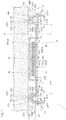
- Fig. 2 is a cross-sectional view illustrating a state in which the load detection sensor unit is attached to S springs of a seat apparatus.
- Fig. 2 is a cross-sectional view of the load detection sensor unit along a surface of the seat apparatus in a right-left direction.
- a load detection sensor unit 1 mainly includes a pedestal 2, a buffering member 3, an upper case 4, and a load detection sensor 5.
- the pedestal 2 includes a mounting portion 21 on which the load detection sensor 5 is mounted and a pair of hooks 22 connected to the mounting portion 21.
- the mounting portion 21 and the pair of hooks 22 are integrated by forming a metal plate, and the plate thickness of the integrated pedestal 2 is 0.8 mm, for example.
- the mounting portion 21 has as large a size as capable of being arranged between two opposed S springs 100 out of a plurality of S springs 100 ( Fig. 2 ) stretched to be arrayed over an opening of a seat frame in a seating apparatus of a vehicle.
- the S spring 100 is a spring meandering in an S shape.
- a surface thereof opposed to a seat cushion SC ( Fig. 2 ) is a mounting surface 21S, and on the mounting surface 21S is arranged a main block 50m of the load detection sensor 5 provided with a switch SW.
- the mounting portion 21 is also provided with a plurality of through holes 20H ( Fig. 1 ) penetrating the mounting portion 21 from the mounting surface 21S to a surface located on the opposite side of the mounting surface 21S.
- the mounting portion 21 is further provided as openings penetrating the mounting portion 21 from the mounting surface 21S to the surface located on the opposite side of the mounting surface 21S with a plurality of locking nail insertion openings 23 ( Fig. 1 ) and case stop openings 24 ( Fig. 1 ).
- the paired hooks 22 are provided respectively at side surface parts of the mounting portion 21 opposed to each other with the mounting portion 21 interposed therebetween.
- the paired hooks 22 are hooked respectively over spring parts serving as parts of the two opposed S springs 100.
- each of the hooks 22 has equal configurations to each other, and each of the hooks 22 includes an inner wall portion 22A, an outer wall portion 22B, an upper wall portion 22C, and an arm portion 22D.
- a space surrounded by the inner wall portion 22A, the outer wall portion 22B, and the upper wall portion 22C is provided with the spring part serving as a part of the S spring 100.
- a buffering member 3 is arranged between the spring part, and the inner wall portion 22A, the outer wall portion 22B, and the upper wall portion 22C.
- the inner wall portion 22A, the outer wall portion 22B, and the upper wall portion 22C can be hooked over and lock the spring part via the buffering member 3.
- the inner wall portion 22A extends in a direction away from the mounting portion 21 along a direction perpendicular to the mounting surface 21S on a side of the mounting portion 21 on which the mounting surface 21S is located.
- the inner wall portion 22A extends to cover an inner portion 100A of the spring part located on the opposed side.
- the inner wall portion 22A contacts a part of an inner side of the buffering member 3 arranged between the inner wall portion 22A and the spring part.
- the outer wall portion 22B extends obliquely with respect to the direction perpendicular to the mounting surface 21S on the side of the mounting portion 21 on which the mounting surface 21S is located and to be closer to the mounting portion 21 as the outer wall portion 22B extends further to the tip end.
- the outer wall portion 22B extends to cover an outer portion 100B of the spring part located on the opposite side of the opposed side.
- the outer wall portion 22B contacts a part of an outer side of the buffering member 3 arranged between the outer wall portion 22B and the spring part and presses the buffering member 3 in a direction from the outer portion 100B to the inner portion 100A of the spring part.
- a pressing part 22PT of the outer wall portion 22B of the hook 22 pressing the buffering member 3 is bent to project toward the pedestal 2.
- the pressing part 22PT is located further downward than a lowermost position P1 of the spring part arranged in the space surrounded by the inner wall portion 22A, the outer wall portion 22B, and the upper wall portion 22C.
- the upper wall portion 22C is located further upward than the mounting surface 21S of the mounting portion 21 and extends to be approximately parallel to the mounting surface 21S.
- the upper wall portion 22C extends to cover an upper portion 100C of the spring part and contacts a part of an upper side of the buffering member 3 arranged between the upper wall portion 22C and the spring part.
- the inner wall portion 22A, the outer wall portion 22B, and the upper wall portion 22C of the hook 22 extend to cover the spring part of the S spring 100 and can hold the spring part to wrap the spring part via the buffering member 3 in three directions of the upper side and both the lateral sides.
- the arm portion 22D is a strip-like part connecting the side portion of the mounting portion 21 and the lower portion of the inner wall portion 22A and separates the spring part arranged in the space surrounded by the inner wall portion 22A, the outer wall portion 22B, and the upper wall portion 22C from the mounting portion 21 of the pedestal 2 by a predetermined distance.
- the mounting surface 21S of the pedestal 2 is located further upward than the lowermost position P1 of the spring part. Also, in this case, the mounting surface 21S of the pedestal 2 is located further downward than an uppermost position P2 of the outer wall portion 22B of the hook 22 covering the upper portion of the spring part and is located further downward than an uppermost position P3 of the spring part.
- the buffering member 3 is a member buffering the contact between the pedestal 2 and the S spring 100.
- the buffering member 3 is arranged between the inner wall portion 22A, the outer wall portion 22B, and the upper wall portion 22C of the hook 22 of the pedestal 2 and the spring part of the S spring 100 arranged in the space surrounded by the inner wall portion 22A, the outer wall portion 22B, and the upper wall portion 22C.
- the buffering member 3 includes a buffering main body 31 and a locking nail 32 that can be hooked on the mounting portion 21 via the locking nail insertion opening 23 provided in the mounting portion 21 of the pedestal 2.
- the locking nail insertion opening 23 is an opening provided in the pedestal 2.
- the buffering main body 31 and the locking nail 32 are integrated by means of resin forming.
- a spring groove 31A On the lower side wall of the buffering main body 31 is provided a spring groove 31A that can cover, pinch, and fit to a part of the S spring 100 from the upper side of the S spring 100.
- the spring groove 31A is provided on the inner circumferential surface thereof with a pair of stopper pieces 31P ( Fig. 2 ) holding the S spring 100 fitted in the spring groove 31A to keep the S spring 100 inside the groove.
- a hooking piece 31B inserted in an opening 220 provided in the outer wall portion 22B of the pedestal 2 to hold the pressing part 22PT.
- the locking nail 32 extending from the sidewall along the mounting surface 21S and then bending and extending toward the mounting surface 21S, and the locking nail 32 can be hooked on the mounting portion 21 via the locking nail insertion opening 23 from the reverse side of the mounting surface 21S.
- the pedestal 2 and the S spring 100 are secured by the buffering member 3 to have a certain positional relationship.
- the spring part and the buffering main body 31 fitted in the spring groove 31A of the buffering main body 31 are held to be wrapped by the hook 22 in the three directions.
- the pedestal 2 and the S spring 100 are secured further firmly.
- Such a buffering member 3 has lower hardness than that of the pedestal 2.
- a material for the buffering member 3 are resins such as acrylonitrile, butadiene, and styrene copolymeric synthetic resin (ABS), polyamide (PA), polypropylene (PP), and polyacetal (POM).
- a material for the pedestal 2 are metals such as spring steel and a stainless steel material and resins such as polycarbonate (PC), polyimide (PI), polybutyleneterephthalate (PBT), a phenol resin, and an epoxy resin.
- the material for the pedestal 2 is preferably a metal to have high hardness.
- the Rockwell hardness of the buffering member 3 is about HRR30 to HRR120, and the Rockwell hardness of the pedestal 2 is about HRB80 to HRC68.
- the Rockwell hardness of the buffering member 3 is in the range from HRR30 to HRR120, an abnormal sound caused by the contact between the pedestal 2 and the S spring 100 can be restricted, and deformation of the buffering material caused by load can be restricted, which is favorable.
- the Rockwell hardness of the pedestal 2 is in a range from HRB80 to HRC68, the pedestal 2 is highly durable while the pedestal 2 is softer than the S spring 100, which is favorable.
- the upper case 4 is a member covering the main block 50m mounted on the mounting surface 21S of the mounting portion 21 to protect the switch SW of the main block 50m and the like.
- the upper case 4 is also a pressing member pressing the switch SW of the load detection sensor 5 as the upper case 4 is pressed by the seat cushion SC as illustrated in Fig. 2 .
- the upper case 4 includes a top wall 45 and a frame wall 48.
- the top wall 45 is a plate-like member formed approximately in a circular shape.
- the frame wall 48 of the upper case 4 is divided into a plurality of pieces and is connected to the outer circumference of the top wall 45.
- a hook piece 47 is connected to the top wall 45.
- Each of the hook pieces 47 is adapted to be fitted into the case stop opening 24 in the mounting portion 21 of the pedestal 2.
- Each of the hook pieces 47 is fitted into the case stop opening 24 to cause relative movement between the pedestal 2 and the upper case 4 in a direction of the mounting surface 21S to be restricted.
- the top wall 45 of the upper case 4 is provided with a pressing portion 46 projecting from the bottom surface thereof opposed to the mounting portion 21 of the pedestal 2.
- the tip end of the pressing portion 46 is formed in a planar shape. Meanwhile, the tip end of the pressing portion 46 may be formed in a protruded curved shape.
- the top wall 45 of the upper case 4 is also provided with a plurality of ribs 49 projecting from the same bottom surface thereof as that provided with the pressing portion 46.
- the ribs 49 are formed at positions overlapping with the plurality of through holes 20H formed in the mounting portion 21 of the pedestal 2.
- the upper case 4 is made of a harder material than the seat cushion SC.
- the pressing portion 46 serving as a part of the upper case 4 is also made of a harder material than the seat cushion SC.
- the seat cushion SC is generally made of a foamed urethane resin
- examples of the material for the upper case 4 are resins such as polycarbonate (PC), polyimide (PI), polybutyleneterephthalate (PBT), a phenol resin, and an epoxy resin.
- an upper surface 45S of the top wall 45 of the upper case 4 is opposed to the lower surface of the seat cushion SC to have a predetermined distance.
- the upper surface 45S is in a planar shape.
- the upper surface 45S is a pressure receiving surface receiving pressure from the seat cushion SC and has a larger area than the area in the pressing portion 46 contacting the switch SW of the load detection sensor 5.
- the load detection sensor 5 includes the switch SW, a flexible switch sheet 50, a metal plate 60, and an adhesive layer 70 attaching the switch sheet 50 to the metal plate 60.
- the switch sheet 50 and the metal plate 60 are attached to each other by the adhesive layer 70.
- the switch sheet 50 is a sheet-like membrane switch and includes an approximately rectangular main block 50m and a tail block 50t connected to the main block 50m and having a shorter width than that of the main block 50m.
- the main block 50m is provided with the switch SW.
- the tail block 50t is provided with a wide blade portion 50f.
- through holes 50H are formed around the respective apexes of the main block 50m.
- the metal plate 60 is attached to one surface of the switch sheet 50 via the adhesive layer 70.
- the metal plate 60 is attached to a cushion-side surface 50mcs, in the main block 50m serving as a part of the switch sheet 50, which is a surface provided on the side of the seat cushion SC of the seat apparatus.
- the cushion-side surface 50mcs has a region overlapping with the switch SW of the switch sheet 50 in a direction perpendicular to the cushion-side surface 50mcs.
- the adhesive layer 70 is a layer member attaching the switch sheet 50 to the metal plate 60.
- the adhesive layer 70 has an equal size to that of the metal plate 60.
- a material for the adhesive layer 70 may be any material as long as the adhesive layer 70 can attach the switch sheet 50 to the metal plate 60, and examples thereof are a thermoplastic resin, a thermosetting resin, and a light curing resin.
- the adhesive layer 70 one including a base material such as PET and a non-woven cloth and adhesive layers formed on both the surfaces of the base material may be used.
- a glass-transition point Tg of the adhesive layer 70 is preferably 85°C or higher.
- the adhesive layer 70 is difficult to flow even under a high-temperature environment such as an in-car environment in the hot sun, and false detection of seating due to the flow of the adhesive layer 70 can thus be restricted.
- Fig. 3 is an exploded view of the load detection sensor 5.
- the switch sheet 50 includes a first electrode sheet 56, a spacer 58, and a second electrode sheet 57.
- the first electrode sheet 56 mainly includes a first insulating sheet 56s, a first electrode 56e, and a first terminal 56c.
- the first insulating sheet 56s is a flexible insulating sheet made of a resin.
- the first insulating sheet 56s includes a main block 56m having an equal shape to that of the main block 50m of the switch sheet 50 and a tail block 56t connected to the main block 56m and having an approximately equal shape to that of the tail block 50t of the switch sheet 50.
- the tail block 56t has a different shape from that of the tail block 50t of the switch sheet 50 in that a tip end part thereof on the opposite side of the main block 56m is narrower than the other parts of the tail block 56t.
- the main block 56m is provided with through holes 56H at similar positions to those of the through holes 50H of the switch sheet 50.
- Examples of a material for the first insulating sheet 56s are resins such as polyethylene terephthalate (PET), polyimide (PI), and polyethylene naphthalate (PEN).
- PET polyethylene terephthalate
- PI polyimide
- PEN polyethylene naphthalate
- an opposite surface of a side opposed to the spacer 58 is a pedestal opposed surface 50mps of the main block 50m of the switch sheet 50 ( Fig. 2 ).
- the first electrode 56e is provided on one surface of the main block 56m approximately at the center.
- the first electrode 56e is a conductive layer such as an approximately circular metal printed layer.
- the first terminal 56c is a conductive layer such as an approximately rectangular metal layer.
- the first terminal 56c is provided at the tip end part on a surface of the tail block 56t provided with the first electrode 56e. Also, the first electrode 56e and the first terminal 56c are electrically connected to each other via a first wire 56w.
- the second electrode sheet 57 mainly includes a second insulating sheet 57s, a second electrode 57e, and a second terminal 57c.
- the second insulating sheet 57s is arranged further on the side of the seat cushion SC than the first electrode sheet 56 ( Fig. 2 ) and is an insulating sheet made of a resin in a similar manner to the first insulating sheet 56s.
- the second insulating sheet 57s includes a main block 57m having an equal shape to that of the main block 56m of the first insulating sheet 56s and a tail block 57t connected to the main block 57m and having an equal shape to that of the tail block 56t of the first insulating sheet 56s except a tip end part.
- the tip end part of the tail block 57t is narrower than the other parts of the tail block 57t.
- the tip end part of the tail block 56t of the first insulating sheet 56s and the tip end part of the tail block 57t of the second insulating sheet 57s do not overlap when the first insulating sheet 56s and the second insulating sheet 57s overlap with each other.
- the main block 57m is provided with through holes 57H at similar positions to those of the through holes 50H of the switch sheet 50.
- Examples of a material for the second insulating sheet 57s are resins such as PET, PI, and PEN in a similar manner to that of the first insulating sheet 56s.
- the material for the second insulating sheet 57s may be equal to or different from the material for the first insulating sheet 56s.
- the second electrode 57e has a similar configuration to that of the first electrode 56e and is provided on one surface of the main block 57m of the second insulating sheet 57s approximately at the center.
- the second electrode 57e is provided at a position at which the second electrode 57e overlaps with the first electrode 56e when the first electrode sheet 56 and the second electrode sheet 57 overlap with each other.
- the second terminal 57c has a similar configuration to that of the first terminal 56c and is provided at the tip end part on a surface of the tail block 57t provided with the second electrode 57e.
- the first terminal 56c and the second terminal 57c are not located between the first insulating sheet 56s and the second insulating sheet 57s but are exposed.
- the second electrode 57e and the second terminal 57c are electrically connected to each other via a second wire 57w.
- the spacer 58 is arranged between the first electrode sheet 56 and the second electrode sheet 57 and is a flexible insulating sheet made of a resin.
- the spacer 58 includes a main block 58m and a tail block 58t connected to the main block 58m.
- the main block 58m has a similar external shape to those of the main blocks 56m and 57m of the first insulating sheet 56s and the second insulating sheet 57s.
- the main block 58m is provided at the center with an opening 58c and is provided with through holes 58H at similar positions to those of the through holes 50H of the switch sheet 50 in a similar manner to those of the first insulating sheet 56s and the second insulating sheet 57s.
- the tail block 58t is formed in a shape of each of the tail blocks 56t and 57t of the first insulating sheet 56s and the second insulating sheet 57s excluding the narrow tip end parts.
- the opening 58c is formed approximately in a circular shape and has a slightly shorter diameter than those of the first electrode 56e and the second electrode 57e.
- the opening 58c is formed to be located inside the circumferences of the first electrode 56e and the second electrode 57e in a case in which the spacer 58 overlaps with the first electrode sheet 56 and the second electrode sheet 57 and is in a planar view.
- the spacer 58 is also provided with a slit 58b connecting a space in the opening 58c to a space outside the switch sheet 50.
- the slit 58b serves as an air vent when the first electrode sheet 56, the spacer 58, and the second electrode sheet 57 overlap with each other.
- the opening 58c may be formed to be located outside the circumferences of the first electrode 56e and the second electrode 57e in a case in which the spacer 58 overlaps with the first electrode sheet 56 and the second electrode sheet 57 and is in a planar view.
- Examples of a material for the spacer 58 are resins such as PET, PI, and PEN in a similar manner to those of the first insulating sheet 56s and the second insulating sheet 57s.
- the material for the spacer 58 may be equal to or different from the material for the first insulating sheet 56s or the second insulating sheet 57s.
- on both surfaces of the spacer 58 is applied not-illustrated adhesive causing the spacer 58 to be attached to the first electrode sheet 56 and the second electrode sheet 57.
- the first electrode 56e and the first wire 56w of the first electrode sheet 56 and the second electrode 57e and the second wire 57w of the second electrode sheet 57 are located between the first insulating sheet 56s and the second insulating sheet 57s.
- the first electrode 56e and the second electrode 57e are opposed via the opening 58c to constitute the switch SW.
- the respective through holes 56H, 57H, and 58H overlap and serve as the through holes 50H of the switch sheet 50.
- first terminal 56c and the second terminal 57c of the switch sheet 50 are respectively connected signal cables 19 connected to a not-illustrated control device.
- the first terminal 56c and the second terminal 57c, and the respective signal cables 19, are connected by means of conductive paste, soldering, or the like.
- the end portion of the tail block 50t of the switch sheet 50 including the first terminal 56c and the second terminal 57c connected to the signal cables 19 is covered with a terminal sealing resin 18 as illustrated in Fig. 1 .
- the terminal sealing resin 18 is made of hot melt or a light curing resin, for example. In this manner, the respective signal cables 19 are restricted from being detached from the respective first and second terminals 56c and 57c, and the first terminal 56c and the second terminal 57c are restricted from shorting due to conductive dust or the like.
- the metal plate 60 is made of a metal plate which is more difficult to flex than the switch sheet 50.
- a material for the metal plate 60 is not particularly limited as long as the material is a conductive metal, and examples thereof are copper and stainless steel.
- the metal plate 60 has an approximately equal shape to that of the main block 50m of the switch sheet 50.
- the metal plate 60 is provided with through holes 60H at similar positions to those of the through holes 50H of the switch sheet 50.
- the through holes 50H of the switch sheet 50 and the through holes 60H of the metal plate 60 overlap with each other. Also, when the switch sheet 50 and the metal plate 60 overlap, the metal plate 60 is attached to the cushion-side surface 50mcs to cover the switch SW of the switch sheet 50 via the adhesive layer 70.
- the load detection sensor 5 configured as above is arranged on the mounting portion 21 of the pedestal 2 as illustrated in Fig. 2 .
- the main block 50m of the switch sheet 50 including the switch SW is located on the mounting portion 21 of the pedestal 2.
- the tail block 50t of the switch sheet 50, the terminal sealing resin 18, and the pair of signal cables 19 are drawn from the pedestal 2.
- the tip end of the pressing portion 46 contacts a position of the metal plate 60 of the load detection sensor 5 overlapping with the switch SW.
- the respective ribs 49 pass through the corresponding through holes 60H of the metal plate 60, through holes 50H of the switch sheet 50, and through holes 20H of the pedestal 2.
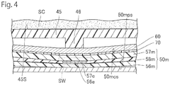
- Fig. 4 illustrates an on state of the load detection sensor 5.
- the lower surface of the seat cushion SC moves downward, contacts the upper surface 45S of the upper case 4, and presses the upper surface 45S.
- the tip end of the pressing portion 46 presses the metal plate 60, and due to flexure of the metal plate 60, the main block 57m of the second insulating sheet 57s also flexes as illustrated in Fig. 4 .
- the pedestal opposed surface 50mps of the main block 56m of the first insulating sheet 56s is not attached to the pedestal 2, at least the peripheral part of the switch SW is deformed to follow the flexure of the metal plate 60.
- the second electrode 57e contacts the first electrode 56e, and the switch SW of the load detection sensor 5 is turned on.
- Seating is then detected by the not-illustrated vehicle control unit connected to the signal cables 19.
- the pedestal 2 of the load detection sensor 5 includes the pair of hooks 22 hooked respectively over the opposed spring parts.
- Each of the paired hooks 22 extends to cover the upper portion 100C in the spring part and the outer portion 100B located on the opposite side of the pedestal 2 in the spring part, and the buffering member 3 is arranged between the spring part and the hook 22.
- the buffering member 3 has lower hardness than that of the pedestal 2.
- the buffering member 3 having lower hardness than that of the pedestal 2 is arranged between the hook 22 of the pedestal 2 and the spring part, a collision of the pedestal 2 with the spring is alleviated, and an abnormal sound caused by the contact between the pedestal 2 and the S spring 100 is difficult to occur.
- the pedestal 2 has higher hardness than that of the buffering member 3, creep deformation is difficult to occur. Since the upper portion 100C and the outer portion 100B in the spring part are covered with the hook 22 of the pedestal 2, relative displacement between the spring part and the hook 22 caused by the creep deformation is difficult to occur. Accordingly, a change of the load weight causing the switch SW of the load detection sensor 5 to be turned on due to the relative displacement between the spring part and the hook 22 is restricted, and the load can be detected appropriately by the load detection sensor 5.
- the load detection sensor unit 1 can detect the load appropriately while restricting generation of the abnormal sound.
- the hook 22 extends to cover the inner portion 100A located on the pedestal side in the spring part.
- the hook 22 since both the sides of the S spring 100 are covered with the hook 22, the relative displacement between the spring part and the hook 22 in a direction perpendicular to a direction in which the S spring 100 is stretched is restricted. Accordingly, the change of the load weight causing the switch SW of the load detection sensor 5 to be turned on can further be restricted.
- the hook 22 presses the buffering member 3 from the outer portion 100B to the inner portion 100A of the spring part.
- the hook 22 settles on the spring part via the buffering member 3. Accordingly, the relative displacement between the spring part and the hook 22 in the direction in which the S spring 100 is stretched and in the perpendicular direction is restricted, and the change of the load weight causing the switch SW of the load detection sensor 5 to be turned on can further be restricted.
- the pressing part 22PT at which the hook 22 presses the buffering member 3, is located further downward than the lowermost position P1 of the spring part. Accordingly, since the hook 22 settles to wrap the spring part via the buffering member 3, the relative displacement between the spring part and the hook 22 can further be restricted.
- the buffering member 3 is fitted to the spring part.
- the buffering member 3 itself arranged between the spring part and the hook 22 can restrict the relative displacement between the spring part and the hook 22, and the pedestal 2 can be settled over the S spring 100 more firmly by both the buffering member 3 and the hook 22.
- the mounting surface 21S of the mounting portion 21 of the pedestal 2 is located further upward than the lowermost position P1 of the spring part. Accordingly, since the mounting surface 21S of the mounting portion 21 does not project further downward than the S spring 100, the pedestal 2 is not interfered with by anything provided below the S spring 100. Also, since the mounting surface 21S of the pedestal 2 is close to the seat cushion SC mounted on the S spring 100, load can be detected appropriately.
- Fig. 5 illustrates the load detection sensor unit according to the second embodiment viewed in the same direction as that in Fig. 2 .
- the load detection sensor unit according to the present embodiment differs from that according to the first embodiment in that, instead of the locking nail 32 of the buffering member 3 in the first embodiment, a locking nail 132 having a different structure from that of the locking nail 32 is employed.
- the locking nail 32 extends approximately in parallel with the mounting surface 21S inward from the inner sidewall of the buffering main body 31 and then bends toward the mounting surface 21S and extends.
- the locking nail 32 is arranged further inward than the inner portions 100A of the opposed S springs 100.
- the locking nail 132 according to the present embodiment extends upward from the upper wall of the buffering main body 31 and is arranged further outward than the inner portions 100A of the opposed S springs 100.
- the buffering main body 31 is hooked on the mounting portion 21 via the locking nail insertion opening 23 from the opposite surface of the mounting surface 21S by such a locking nail 132.
- the load detection sensor unit since the locking nail 32 does not exist further inward than the inner portions 100A of the S springs 100 as in the first embodiment, restriction on arrangement of the load detection sensor 5 due to the locking nail 132 is alleviated. Accordingly, even in a case in which the distance between the opposed spring parts is short, or in which the load detection sensor 5 is relatively large, the load detection sensor 5 can be arranged in a stable manner.
- the load detection sensor unit according to the present embodiment also differs from that according to the first embodiment in that, instead of the pedestal 2 including the pair of hooks 22 according to the first embodiment, a pedestal 120 including a pair of hooks 122 having a different structure from that of the pair of hooks 22 is employed.
- the paired hooks 122 have the same configurations with each other.
- Each of the hooks 122 includes an inner wall portion 122A different from that in the first embodiment, and the outer wall portion 22B and the upper wall portion 22C equal to those in the first embodiment, and omits the arm portion 22D according to the first embodiment.
- the inner wall portion 22A according to the first embodiment extends along the direction perpendicular to the mounting surface 21S of the mounting portion 21, the inner wall portion 122A according to the present embodiment extends obliquely with respect to the mounting surface 21S. Due to the inner wall portion 122A, the mounting surface 21S is located further downward than the uppermost position P2 of the outer wall portion 22B of the hook 122.
- the mounting surface 21S is located further upward than the lowermost position P1 of the spring part surrounded by the hook 122. Also, the mounting surface 21S according to the present embodiment is located further upward than the uppermost position P3 of the spring part and is connected to the hook 122 not covering the inner portion 100A of the spring part at a further upward position than the uppermost position P3 of the spring part.
- a level difference SP ( Fig. 2 ) between the region over the spring part and the region provided with the load detection sensor 5 in the pedestal 2 can be reduced. Accordingly, restriction on arrangement of the load detection sensor 5 due to the level difference SP of the pedestal 2 is alleviated, and even in a case in which the distance between the opposed spring parts is short, or in which the load detection sensor 5 is relatively large, the load detection sensor 5 can be arranged in a stable manner.
- a pedestal 220 including a hook 222 illustrated in Fig. 6 may be employed.
- the hook 222 does not cover the inner portion 100A of the spring part but covers the outer portion 100B and the upper portion 100C.
- an inner wall portion 222A of the hook 222 extends obliquely so that the mounting surface 21S may be located further upward than the uppermost position P2 of the outer wall portion 22B covering the upper portion 100C of the spring part.
- Fig. 7 illustrates the load detection sensor unit according to the third embodiment viewed in the same direction as that in Fig. 2 .
- the load detection sensor unit according to the present embodiment differs from that according to the second embodiment in that, instead of the pedestal 120 including the hook 122 in the second embodiment, a pedestal 320 including a hook 322 having a different structure from that of the hook 122 is employed.
- the hook 322 does not cover the inner portion 100A of the spring part but covers the outer portion 100B and the upper portion 100C. Also, in the hook 322, the inner wall portion 122A according to the second embodiment extending obliquely with respect to the mounting surface 21S is omitted, and the mounting surface 21S is at an equal height to the uppermost position P2 of the part of the hook 322 covering the upper portion 100C of the spring part.
- the inner wall portion 122A according to the second embodiment extending obliquely with respect to the mounting surface 21S is omitted, and the load detection sensor 5 and the hook 322 can get closer to each other as much as the length of the inner wall portion 122A. Accordingly, even in a case in which the distance between the opposed spring parts is short, the load detection sensor 5 can be arranged in a stable manner.
- the pedestal 2 is arranged between the spring parts in the two opposed S springs 100 out of the plurality of S springs 100 stretched to be arrayed over an opening 151 of a frame 150.
- the pedestal 2 may be arranged between opposed spring parts in one S spring 100 out of the plurality of S springs 100 stretched to be arrayed over the opening 151 of the frame 150.
- the opposed spring parts in the S spring 100 are a spring part 101 extending on one side and a spring part 102 extending on the other side from a bent position P having the highest curvature in the bent part of the S spring 100.
- each of the pedestal 120 according to the second embodiment and the pedestal 320 according to the third embodiment is arranged between the spring parts in the two opposed S springs 100
- each of the pedestals may be arranged between opposed spring parts in one S spring 100.
- the pedestal 120 according to the second embodiment or the pedestal 320 according to the third embodiment is more useful than the pedestal 2 according to the first embodiment.
- the S spring 100 meandering in an S shape is employed as the spring stretched to be arrayed over the opening of the seat frame.
- a spring meandering in a rectangular wave shape may be employed, for example.
- the springs formed in various shapes are applicable as long as the springs are the plurality of springs stretched to be arrayed over the opening of the seat frame, and the spring preferably has a bent part by meandering or the like.
- the hook 22 is hooked on a linear part of the S spring 100, and the buffering member 3 is fitted only to the linear part.
- a part on which the hook 22 is hooked may not be the linear part of the S spring 100.
- the part on which the hook 22 is hooked is preferably the linear part of the S spring 100.
- the buffering member 3 may extend to a part except the spring part on which the hook 22 is hooked.
- the buffering members 3 each extending to the part except the spring part on which the hook is hooked are illustrated in Figs. 10 and 11 .
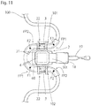
- the buffering member 3 illustrated in Fig. 11 extends from a spring part on which the hook 22 is hooked to the first bent portion FP1 and from the spring part to the second bent portion FP2.
- the spring 100 is fitted from the spring part on which the hook 22 is hooked to the first bent portion FP1 and the second bent portion FP2.
- the spring is covered with the buffering member 3 from the spring part on which the hook 22 is hooked to the first bent portion FP1 and the second bent portion FP2. Accordingly, relative displacement between the spring 100 and the buffering member 3 can further be restricted, and the pedestal 2 can be settled over the spring more firmly by both the buffering member 3 and the hook 22.
- each of the buffering members 3 illustrated in Figs. 10 and 11 extends from the spring part on which the hook 22 is hooked to the first bent portion FP1 and from the spring part to the second bent portion FP2.
- the buffering member 3 may extend from the spring part on which the hook 22 is hooked to the first bent portion FP1 and, on the side of the second bent portion FP2, extend from the spring part to the hooking part of the hook 22 in the S spring 100 in a similar manner to the above embodiments.
- the buffering member 3 may extend from the spring part on which the hook 22 is hooked to the second bent portion FP2 and, on the side of the first bent portion FP1, extend from the spring part to the hooking part of the hook 22 in the S spring 100 in a similar manner to the above embodiments.
- each of the buffering members 3 illustrated in Figs. 10 and 11 may extend from the spring part on which the hook 22 is hooked to pass the first bent portion FP1 to one side of the spring 100.
- the buffering member 3 preferably extends to a bent position F1 having the highest curvature in the first bent portion FP1 or goes over the bent position F1.
- the buffering member 3 has only to extend to the first bent portion FP1 and may not reach the bent position F1 of the first bent portion FP1.
- each of the buffering members 3 illustrated in Figs. 10 and 11 may extend from the spring part on which the hook 22 is hooked to pass the second bent portion FP2 to the other side of the spring 100.
- the buffering member 3 preferably extends to a bent position F2 having the highest curvature in the second bent portion FP2 or goes over the bent position F2.
- the buffering member 3 has only to extend to the second bent portion FP2 and may not reach the bent position F2 of the second bent portion FP2.
- the main block 50m including the switch SW and being larger than the switch SW is arranged on the mounting surface 21S of the pedestal 2 or 120.
- a part of the main block 50m and the tail block 50t may be arranged on the mounting surface 21S, or the entire switch sheet 50 may be arranged on the mounting surface 21S.
- at least a part of the load detection sensor 5 including the switch SW has only to be arranged on the mounting surface 21S.
- the so-called membrane switch load detection sensor 5 has been applied. That is, the load detection sensor 5 includes the pair of opposed insulating sheets 56s and 57s and the spacer 58 arranged between the insulating sheets 56s and 57s. The load detection sensor 5 also includes the pair of electrodes 56e and 57e opposed to be spaced from each other via the opening 58c of the spacer 58 and provided respectively on the opposed surfaces of the paired insulating sheets 56s and 57s and the metal plate 60 provided on the surface of the insulating sheet 57s which is an opposite side of a side on which the electrode 57e is provided.
- a load detection sensor having a different configuration from that of the load detection sensor 5 according to the above embodiments can be applied as long as the load detection sensor is one detecting load.
- the load detection sensor is one detecting load.
- the insulating sheet 56s instead of the insulating sheet 56s, a substrate having no flexibility may be employed. Also, the insulating sheet 57s may be omitted, and the metal plate 60 may function as the insulating sheet 57s and the electrode 57e.
- an electrostatic-capacitance-type load detection sensor may be applied in which, instead of the spacer 58, a flexible sheet-like spacer omitting the opening 58c is employed, in which the spacer flexes in response to a pressing force, and in which load is detected based on electrostatic capacitance which changes as the distance between the electrodes 56e and 57e opposed with the spacer interposed therebetween is reduced.
- the upper case 4 may be omitted.
- the respective components of the above load detection sensor unit can not only be used as described in the above embodiments and modifications but can also be combined, omitted, changed, or mixed with known techniques as needed without departing from the object of the present invention.
- the present invention is applicable as long as the present invention is arranged under a seat cushion, is attached to a plurality of springs stretched to be arrayed over an opening of a frame, and detects load applied from a detected target. That is, although, in the above embodiments, the load detection sensor unit is attached to the plurality of springs stretched to be arrayed over the opening of the vehicle frame and detects pressure resulting from seating of a person, other embodiments can be employed instead of the above embodiments. For example, an embodiment is raised as an example in which the load detection sensor unit is attached to a plurality of springs stretched to be arrayed over an opening of a frame under a seat cushion of a care bed.
- an elastic member may be used as the seat cushion.
- any material may be used as long as the material has an elastic force and enables load from a detected target to be transmitted to the load detection sensor unit, and examples of the material for the elastic member are urethane, silicon, and ethylene propylene.
Landscapes
- Engineering & Computer Science (AREA)
- Mechanical Engineering (AREA)
- Aviation & Aerospace Engineering (AREA)
- Transportation (AREA)
- Automation & Control Theory (AREA)
- Seats For Vehicles (AREA)
- Chair Legs, Seat Parts, And Backrests (AREA)
Abstract
Description
- The present invention relates to a load detection sensor unit appropriate for a case of detecting load due to seating or the like.
- As one of safety systems in a vehicle, an alarm system in which a failure to use a seat belt during a ride is warned has been put to practical use. In this alarm system, a warning is generated in a case in which use of a seat belt is detected in a state in which person's seating is detected. As a device of detecting the person's seating, a load detection sensor detecting load due to seating is used in some cases.
- Disclosed as a load detection sensor is one arranged under a seat cushion arranged on a plurality of springs stretched to be arrayed over an opening of a frame (refer to
Patent Literature 1 shown below). The load detection sensor inPatent Literature 1 shown below is mounted on a pedestal, and the pedestal is arranged between the two springs opposed to each other. The pedestal is provided with a pair of hooks. One of the hooks is attached to one of the two springs opposed to each other while the other of the hooks is attached to the other of the two springs. - [Patent Literature 1]
JP 2011-105278 A - In a case in which the pedestal in
Patent Literature 1 shown above is made of a relatively hard member such as a metal, an abnormal sound is easy to be generated due to contact between the pedestal and the springs. On the other hand, in a case in which the pedestal inPatent Literature 1 shown above is made of a relatively soft member such as a resin, the pedestal is creep-deformed in response to repetitive pressure, and the creep deformation easily causes relative displacement between the springs and the hooks. For this reason, due to the relative displacement between the springs and the hooks, the load weight causing the load detection sensor to be turned on may change, and there is concern that the load may not be able to be detected appropriately. In particular, since the creep deformation highly possibly occurs under a high-temperature environment, there is additional concern that the load may not be able to be detected appropriately due to the relative displacement between the springs and the hooks. - An object of the present invention is to provide a load detection sensor unit enabling load to be detected appropriately while restricting generation of an abnormal sound.
- To solve the above problem, a load detection sensor unit according to the present invention is a load detection sensor unit arranged under a seat cushion and includes a load detection sensor detecting load, a pedestal including a mounting portion on which the load detection sensor is mounted and attached to at least opposed spring parts out of a plurality of springs stretched to be arrayed over an opening of a frame, and a buffering member arranged at least at a part between the spring part and the pedestal. The pedestal includes a pair of hooks hooked respectively over the opposed spring parts. Each of the hooks extends to cover at least an upper portion of the spring part and an outer portion of the spring part located on an opposite side of the opposed side. The buffering member has lower hardness than that of the pedestal and is arranged between the hook and the spring part.
- In such a load detection sensor unit, since the buffering member having lower hardness than that of the pedestal is arranged between the hook of the pedestal and the spring part, a collision of the pedestal with the spring is alleviated, and an abnormal sound caused by the contact between the pedestal and the spring is difficult to occur.
- Also, since the pedestal has higher hardness than that of the buffering member, creep deformation is difficult to occur. Thus, relative displacement between the spring part, whose upper portion and outer portion are covered with the hook of the pedestal, and the hook, caused by the creep deformation, is difficult to occur. Accordingly, a change of the load weight causing the load detection sensor to be turned on due to the relative displacement between the spring part and the hook is restricted, and the load can be detected appropriately by the load detection sensor.
- In this manner, the load detection sensor unit that can detect the load appropriately while restricting generation of the abnormal sound is provided.
- Also, the hook preferably presses the buffering member from the outer portion to an inner portion of the spring part.
- In this case, due to pressing by means of the hook, the hook can settle on the spring part via the buffering member. Accordingly, the relative displacement between the spring part and the hook in the direction in which the spring is stretched and in the perpendicular direction is restricted. Consequently, the change of the load weight causing the load detection sensor to be turned on can further be restricted.
- Also, a part of the buffering member that the hook presses is preferably located further downward than a lowermost position of the spring part.
- In this case, since the hook can settle to wrap the spring part via the buffering member, the relative displacement between the spring part and the hook can further be restricted.
- Also, the buffering member is preferably fitted to the spring part.
- In this case, the buffering member itself arranged between the spring part and the hook can restrict the relative displacement between the spring part and the hook, and the pedestal can be settled over the spring more firmly by both the buffering member and the hook.
- Also, the buffering member preferably extends either/both to a closest first bent portion toward a first end side of the spring from the spring part on which the hook is hooked or/and to a closest second bent portion toward a second end side of the spring from the spring part.
- In this case, the spring is covered with the buffering member from the spring part on which the hook is hooked to either/both the first bent portion or/and the second bent portion. Accordingly, relative displacement between the spring and the buffering member can further be restricted, and the pedestal can be settled over the spring more firmly by both the buffering member and the hook.
- Also, each of the hooks preferably extends to cover the inner portion of the spring part located on the opposed side.
- In this case, since both the sides of the spring are covered with the hook, the relative displacement between the spring part and the hook in a direction perpendicular to a direction in which the spring is stretched is restricted. Accordingly, the change of the load weight causing the load detection sensor to be turned on can further be restricted.
- Also, a mounting surface of the mounting portion is preferably located further upward than the lowermost position of the spring part.
- In this case, since the mounting surface does not project further downward than the spring, the pedestal is not interfered with by anything provided below the spring. Also, since the mounting surface of the pedestal is close to the seat cushion mounted on the spring, load can be detected appropriately.
- Also, the mounting surface of the mounting portion is preferably located further upward than an uppermost position of the spring part and is preferably connected to the hook at a further upward position than the uppermost position of the spring part.
- Since the mounting surface is located further upward than the uppermost position of the spring part and is connected to the hook at the further upward position than the uppermost position of the spring, a level difference between the region over the spring part and the region provided with the load detection sensor in the pedestal can be reduced. Accordingly, restriction on arrangement of the load detection sensor due to the level difference of the pedestal is alleviated, and even in a case in which the distance between the opposed spring parts is short, or in which the load detection sensor is relatively large, the load detection sensor can be arranged in a stable manner.
- Also, the mounting surface is preferably located at an equal height to or further upward than an uppermost position of a part of the hook covering an upper portion of the spring part.
- Since the mounting surface is located further upward than the uppermost position of the hook covering the spring, it is possible to restrict the region provided with the load detection sensor from being interfered with by the region over the spring part. Accordingly, restriction on arrangement of the load detection sensor can further be alleviated.
- Also, the buffering member preferably includes a locking nail that can be hooked on the pedestal via an opening provided in the pedestal, and the locking nail is preferably arranged further outward than the inner portion of each of the opposed spring parts.
- In this case, since the locking nail does not exist further inward than the inner portions of the spring parts, restriction on arrangement of the load detection sensor due to the locking nail is alleviated. Accordingly, even in a case in which the distance between the opposed spring parts is short, or in which the load detection sensor is relatively large, the load detection sensor can be arranged in a stable manner.
- As described above, according to the present invention, it is possible to provide a load detection sensor unit enabling load to be detected appropriately while restricting generation of an abnormal sound.
-
-
Fig. 1 is an exploded view illustrating a configuration of a load detection sensor unit according to a first embodiment. -
Fig. 2 is a cross-sectional view illustrating a state in which the load detection sensor unit is attached to S springs. -
Fig. 3 is an exploded view of a load detection sensor. -
Fig. 4 illustrates an on state of the load detection sensor. -
Fig. 5 illustrates the load detection sensor unit according to a second embodiment viewed in the same direction as that inFig. 2 . -
Fig. 6 illustrates a case in which a mounting surface of a pedestal of the load detection sensor unit according to the second embodiment is located further upward than a hook viewed in the same direction as that inFig. 2 . -
Fig. 7 illustrates the load detection sensor unit according to a third embodiment viewed in the same direction as that inFig. 2 . -
Fig. 8 schematically illustrates a state of the pedestal arranged between spring parts in the two opposed S springs in a case in which the upper portion of the S springs is in a planar view. -
Fig. 9 schematically illustrates a state of the pedestal arranged between spring parts in one S spring in a case in which the upper portion of the S springs is in a planar view. -
Fig. 10 illustrates a state in which a buffering member of the pedestal illustrated inFig. 8 extends to a part except the S spring on which the hook is hooked. -
Fig. 11 illustrates a state in which a buffering member of the pedestal illustrated inFig. 9 extends to a part except the S spring on which the hook is hooked. - Hereinbelow, preferred embodiments of a load detection sensor unit according to the present invention will be described in detail with reference to the drawings. It is to be noted that the scale of the respective figures may differ from the scale in the below description to facilitate understanding.
-
Fig. 1 is an exploded view illustrating a configuration of a load detection sensor unit according to a first embodiment, andFig. 2 is a cross-sectional view illustrating a state in which the load detection sensor unit is attached to S springs of a seat apparatus. It is to be noted thatFig. 2 is a cross-sectional view of the load detection sensor unit along a surface of the seat apparatus in a right-left direction. As illustrated inFigs. 1 and2 , a loaddetection sensor unit 1 mainly includes apedestal 2, a bufferingmember 3, anupper case 4, and aload detection sensor 5. - The
pedestal 2 includes a mountingportion 21 on which theload detection sensor 5 is mounted and a pair ofhooks 22 connected to the mountingportion 21. In a case of the present embodiment, the mountingportion 21 and the pair ofhooks 22 are integrated by forming a metal plate, and the plate thickness of theintegrated pedestal 2 is 0.8 mm, for example. - The mounting
portion 21 has as large a size as capable of being arranged between two opposed S springs 100 out of a plurality of S springs 100 (Fig. 2 ) stretched to be arrayed over an opening of a seat frame in a seating apparatus of a vehicle. TheS spring 100 is a spring meandering in an S shape. - In the mounting
portion 21, a surface thereof opposed to a seat cushion SC (Fig. 2 ) is a mountingsurface 21S, and on the mountingsurface 21S is arranged amain block 50m of theload detection sensor 5 provided with a switch SW. The mountingportion 21 is also provided with a plurality of throughholes 20H (Fig. 1 ) penetrating the mountingportion 21 from the mountingsurface 21S to a surface located on the opposite side of the mountingsurface 21S. The mountingportion 21 is further provided as openings penetrating the mountingportion 21 from the mountingsurface 21S to the surface located on the opposite side of the mountingsurface 21S with a plurality of locking nail insertion openings 23 (Fig. 1 ) and case stop openings 24 (Fig. 1 ). - The paired hooks 22 are provided respectively at side surface parts of the mounting
portion 21 opposed to each other with the mountingportion 21 interposed therebetween. The paired hooks 22 are hooked respectively over spring parts serving as parts of the two opposed S springs 100. - Also, the paired hooks 22 have equal configurations to each other, and each of the
hooks 22 includes aninner wall portion 22A, anouter wall portion 22B, anupper wall portion 22C, and anarm portion 22D. A space surrounded by theinner wall portion 22A, theouter wall portion 22B, and theupper wall portion 22C is provided with the spring part serving as a part of theS spring 100. Between the spring part, and theinner wall portion 22A, theouter wall portion 22B, and theupper wall portion 22C, a bufferingmember 3 is arranged. In thehook 22, theinner wall portion 22A, theouter wall portion 22B, and theupper wall portion 22C can be hooked over and lock the spring part via thebuffering member 3. - The
inner wall portion 22A extends in a direction away from the mountingportion 21 along a direction perpendicular to the mountingsurface 21S on a side of the mountingportion 21 on which the mountingsurface 21S is located. In a case in which the spring part is arranged in the space surrounded by theinner wall portion 22A, theouter wall portion 22B, and theupper wall portion 22C, theinner wall portion 22A extends to cover aninner portion 100A of the spring part located on the opposed side. In this case, theinner wall portion 22A contacts a part of an inner side of the bufferingmember 3 arranged between theinner wall portion 22A and the spring part. - The
outer wall portion 22B extends obliquely with respect to the direction perpendicular to the mountingsurface 21S on the side of the mountingportion 21 on which the mountingsurface 21S is located and to be closer to the mountingportion 21 as theouter wall portion 22B extends further to the tip end. In a case in which the spring part is arranged in the space surrounded by theinner wall portion 22A, theouter wall portion 22B, and theupper wall portion 22C, theouter wall portion 22B extends to cover anouter portion 100B of the spring part located on the opposite side of the opposed side. In this case, theouter wall portion 22B contacts a part of an outer side of the bufferingmember 3 arranged between theouter wall portion 22B and the spring part and presses the bufferingmember 3 in a direction from theouter portion 100B to theinner portion 100A of the spring part. A pressing part 22PT of theouter wall portion 22B of thehook 22 pressing thebuffering member 3 is bent to project toward thepedestal 2. The pressing part 22PT is located further downward than a lowermost position P1 of the spring part arranged in the space surrounded by theinner wall portion 22A, theouter wall portion 22B, and theupper wall portion 22C. - The
upper wall portion 22C is located further upward than the mountingsurface 21S of the mountingportion 21 and extends to be approximately parallel to the mountingsurface 21S. In a case in which the spring part is arranged in the space surrounded by theinner wall portion 22A, theouter wall portion 22B, and theupper wall portion 22C, theupper wall portion 22C extends to cover anupper portion 100C of the spring part and contacts a part of an upper side of the bufferingmember 3 arranged between theupper wall portion 22C and the spring part. - In this manner, the
inner wall portion 22A, theouter wall portion 22B, and theupper wall portion 22C of thehook 22 extend to cover the spring part of theS spring 100 and can hold the spring part to wrap the spring part via thebuffering member 3 in three directions of the upper side and both the lateral sides. - The
arm portion 22D is a strip-like part connecting the side portion of the mountingportion 21 and the lower portion of theinner wall portion 22A and separates the spring part arranged in the space surrounded by theinner wall portion 22A, theouter wall portion 22B, and theupper wall portion 22C from the mountingportion 21 of thepedestal 2 by a predetermined distance. - In this manner, in a case in which the paired hooks 22 are hooked over the spring parts of the two S springs 100 via the
buffering members 3, the mountingsurface 21S of thepedestal 2 is located further upward than the lowermost position P1 of the spring part. Also, in this case, the mountingsurface 21S of thepedestal 2 is located further downward than an uppermost position P2 of theouter wall portion 22B of thehook 22 covering the upper portion of the spring part and is located further downward than an uppermost position P3 of the spring part. - The buffering
member 3 is a member buffering the contact between thepedestal 2 and theS spring 100. The bufferingmember 3 is arranged between theinner wall portion 22A, theouter wall portion 22B, and theupper wall portion 22C of thehook 22 of thepedestal 2 and the spring part of theS spring 100 arranged in the space surrounded by theinner wall portion 22A, theouter wall portion 22B, and theupper wall portion 22C. - The buffering
member 3 includes a bufferingmain body 31 and a lockingnail 32 that can be hooked on the mountingportion 21 via the lockingnail insertion opening 23 provided in the mountingportion 21 of thepedestal 2. The lockingnail insertion opening 23 is an opening provided in thepedestal 2. In the case of the present embodiment, the bufferingmain body 31 and the lockingnail 32 are integrated by means of resin forming. - On the lower side wall of the buffering
main body 31 is provided aspring groove 31A that can cover, pinch, and fit to a part of theS spring 100 from the upper side of theS spring 100. Thespring groove 31A is provided on the inner circumferential surface thereof with a pair ofstopper pieces 31P (Fig. 2 ) holding theS spring 100 fitted in thespring groove 31A to keep theS spring 100 inside the groove. - Also, on the external sidewall of the buffering
main body 31 is provided a hookingpiece 31B inserted in anopening 220 provided in theouter wall portion 22B of thepedestal 2 to hold the pressing part 22PT. Further, on the internal sidewall of the bufferingmain body 31 is provided the lockingnail 32 extending from the sidewall along the mountingsurface 21S and then bending and extending toward the mountingsurface 21S, and the lockingnail 32 can be hooked on the mountingportion 21 via the lockingnail insertion opening 23 from the reverse side of the mountingsurface 21S. - In a state in which the spring part is fitted in the
spring groove 31A of the bufferingmain body 31, and in which the lockingnail 32 is hooked through the lockingnail insertion opening 23 of the mountingportion 21, thepedestal 2 and theS spring 100 are secured by the bufferingmember 3 to have a certain positional relationship. In this state, in a case in which a part of the pressing member 22PT of thehook 22 is inserted into the hookingpiece 31B of the bufferingmain body 31, the spring part and the bufferingmain body 31 fitted in thespring groove 31A of the bufferingmain body 31 are held to be wrapped by thehook 22 in the three directions. Hence, thepedestal 2 and theS spring 100 are secured further firmly. - Such a
buffering member 3 has lower hardness than that of thepedestal 2. Examples of a material for thebuffering member 3 are resins such as acrylonitrile, butadiene, and styrene copolymeric synthetic resin (ABS), polyamide (PA), polypropylene (PP), and polyacetal (POM). Also, examples of a material for thepedestal 2 are metals such as spring steel and a stainless steel material and resins such as polycarbonate (PC), polyimide (PI), polybutyleneterephthalate (PBT), a phenol resin, and an epoxy resin. The material for thepedestal 2 is preferably a metal to have high hardness. - The Rockwell hardness of the buffering
member 3 is about HRR30 to HRR120, and the Rockwell hardness of thepedestal 2 is about HRB80 to HRC68. In a case in which the Rockwell hardness of the bufferingmember 3 is in the range from HRR30 to HRR120, an abnormal sound caused by the contact between thepedestal 2 and theS spring 100 can be restricted, and deformation of the buffering material caused by load can be restricted, which is favorable. Also, in a case in which the Rockwell hardness of thepedestal 2 is in a range from HRB80 to HRC68, thepedestal 2 is highly durable while thepedestal 2 is softer than theS spring 100, which is favorable. - The
upper case 4 is a member covering themain block 50m mounted on the mountingsurface 21S of the mountingportion 21 to protect the switch SW of themain block 50m and the like. Theupper case 4 is also a pressing member pressing the switch SW of theload detection sensor 5 as theupper case 4 is pressed by the seat cushion SC as illustrated inFig. 2 . - The
upper case 4 includes atop wall 45 and aframe wall 48. Thetop wall 45 is a plate-like member formed approximately in a circular shape. Also, theframe wall 48 of theupper case 4 is divided into a plurality of pieces and is connected to the outer circumference of thetop wall 45. At each space between the plurality of divided pieces of theframe wall 48, ahook piece 47 is connected to thetop wall 45. Each of thehook pieces 47 is adapted to be fitted into the case stop opening 24 in the mountingportion 21 of thepedestal 2. Each of thehook pieces 47 is fitted into the case stop opening 24 to cause relative movement between thepedestal 2 and theupper case 4 in a direction of the mountingsurface 21S to be restricted. - The
top wall 45 of theupper case 4 is provided with apressing portion 46 projecting from the bottom surface thereof opposed to the mountingportion 21 of thepedestal 2. The tip end of thepressing portion 46 is formed in a planar shape. Meanwhile, the tip end of thepressing portion 46 may be formed in a protruded curved shape. - The
top wall 45 of theupper case 4 is also provided with a plurality ofribs 49 projecting from the same bottom surface thereof as that provided with thepressing portion 46. Theribs 49 are formed at positions overlapping with the plurality of throughholes 20H formed in the mountingportion 21 of thepedestal 2. In a state in which theupper case 4 covers theload detection sensor 5 mounted on the mountingportion 21 of thepedestal 2, and in which therespective hook pieces 47 are fitted in the respective case stopopenings 24, therespective ribs 49 are inserted in the corresponding throughholes 20H. Accordingly, even in a case in which the entire sheet surface of theload detection sensor 5 is not attached to the mountingportion 21, relative movement between the switch SW of theload detection sensor 5 and thepressing portion 46 of theupper case 4 in the direction of the mountingsurface 21S is restricted. Meanwhile, in the case of the present embodiment, although the tip end of thepressing portion 46 contacts theload detection sensor 5 in a state in which theupper case 4 covers theload detection sensor 5 mounted on the mountingportion 21, and in which thehook pieces 47 are fitted in the corresponding case stopopenings 24, the tip end of thepressing portion 46 may not contact theload detection sensor 5. - The
upper case 4 is made of a harder material than the seat cushion SC. Hence, thepressing portion 46 serving as a part of theupper case 4 is also made of a harder material than the seat cushion SC. Since the seat cushion SC is generally made of a foamed urethane resin, examples of the material for theupper case 4 are resins such as polycarbonate (PC), polyimide (PI), polybutyleneterephthalate (PBT), a phenol resin, and an epoxy resin. - In a state in which such a load
detection sensor unit 1 is attached to the pair of S springs 100, anupper surface 45S of thetop wall 45 of theupper case 4 is opposed to the lower surface of the seat cushion SC to have a predetermined distance. Theupper surface 45S is in a planar shape. Theupper surface 45S is a pressure receiving surface receiving pressure from the seat cushion SC and has a larger area than the area in thepressing portion 46 contacting the switch SW of theload detection sensor 5. - The
load detection sensor 5 includes the switch SW, aflexible switch sheet 50, ametal plate 60, and anadhesive layer 70 attaching theswitch sheet 50 to themetal plate 60. Theswitch sheet 50 and themetal plate 60 are attached to each other by theadhesive layer 70. - The
switch sheet 50 is a sheet-like membrane switch and includes an approximately rectangularmain block 50m and atail block 50t connected to themain block 50m and having a shorter width than that of themain block 50m. Themain block 50m is provided with the switch SW. Also, thetail block 50t is provided with awide blade portion 50f. Around the respective apexes of themain block 50m, throughholes 50H are formed. - As illustrated in
Fig. 2 , themetal plate 60 is attached to one surface of theswitch sheet 50 via theadhesive layer 70. In the present embodiment, themetal plate 60 is attached to a cushion-side surface 50mcs, in themain block 50m serving as a part of theswitch sheet 50, which is a surface provided on the side of the seat cushion SC of the seat apparatus. The cushion-side surface 50mcs has a region overlapping with the switch SW of theswitch sheet 50 in a direction perpendicular to the cushion-side surface 50mcs. - The
adhesive layer 70 is a layer member attaching theswitch sheet 50 to themetal plate 60. In the present embodiment, theadhesive layer 70 has an equal size to that of themetal plate 60. A material for theadhesive layer 70 may be any material as long as theadhesive layer 70 can attach theswitch sheet 50 to themetal plate 60, and examples thereof are a thermoplastic resin, a thermosetting resin, and a light curing resin. Also, as theadhesive layer 70, one including a base material such as PET and a non-woven cloth and adhesive layers formed on both the surfaces of the base material may be used. A glass-transition point Tg of theadhesive layer 70 is preferably 85°C or higher. In a case in which the glass-transition point Tg is 85°C or higher, theadhesive layer 70 is difficult to flow even under a high-temperature environment such as an in-car environment in the hot sun, and false detection of seating due to the flow of theadhesive layer 70 can thus be restricted. - Next, the
load detection sensor 5 will be described further in detail. -
Fig. 3 is an exploded view of theload detection sensor 5. As illustrated inFig. 3 , theswitch sheet 50 includes afirst electrode sheet 56, aspacer 58, and asecond electrode sheet 57. Thefirst electrode sheet 56 mainly includes a first insulatingsheet 56s, afirst electrode 56e, and afirst terminal 56c. - The first insulating
sheet 56s is a flexible insulating sheet made of a resin. The first insulatingsheet 56s includes amain block 56m having an equal shape to that of themain block 50m of theswitch sheet 50 and atail block 56t connected to themain block 56m and having an approximately equal shape to that of thetail block 50t of theswitch sheet 50. Thetail block 56t has a different shape from that of thetail block 50t of theswitch sheet 50 in that a tip end part thereof on the opposite side of themain block 56m is narrower than the other parts of thetail block 56t. Also, themain block 56m is provided with throughholes 56H at similar positions to those of the throughholes 50H of theswitch sheet 50. Examples of a material for the first insulatingsheet 56s are resins such as polyethylene terephthalate (PET), polyimide (PI), and polyethylene naphthalate (PEN). In themain block 56m of the first insulatingsheet 56s, an opposite surface of a side opposed to thespacer 58 is a pedestal opposed surface 50mps of themain block 50m of the switch sheet 50 (Fig. 2 ). - The
first electrode 56e is provided on one surface of themain block 56m approximately at the center. Thefirst electrode 56e is a conductive layer such as an approximately circular metal printed layer. Thefirst terminal 56c is a conductive layer such as an approximately rectangular metal layer. Thefirst terminal 56c is provided at the tip end part on a surface of thetail block 56t provided with thefirst electrode 56e. Also, thefirst electrode 56e and thefirst terminal 56c are electrically connected to each other via afirst wire 56w. - The
second electrode sheet 57 mainly includes a second insulatingsheet 57s, asecond electrode 57e, and asecond terminal 57c. - The second insulating
sheet 57s is arranged further on the side of the seat cushion SC than the first electrode sheet 56 (Fig. 2 ) and is an insulating sheet made of a resin in a similar manner to the first insulatingsheet 56s. In the case of the present embodiment, the second insulatingsheet 57s includes amain block 57m having an equal shape to that of themain block 56m of the first insulatingsheet 56s and atail block 57t connected to themain block 57m and having an equal shape to that of thetail block 56t of the first insulatingsheet 56s except a tip end part. The tip end part of thetail block 57t is narrower than the other parts of thetail block 57t. The tip end part of thetail block 56t of the first insulatingsheet 56s and the tip end part of thetail block 57t of the second insulatingsheet 57s do not overlap when the first insulatingsheet 56s and the second insulatingsheet 57s overlap with each other. In a similar manner to that in the first insulatingsheet 56s, themain block 57m is provided with throughholes 57H at similar positions to those of the throughholes 50H of theswitch sheet 50. Examples of a material for the second insulatingsheet 57s are resins such as PET, PI, and PEN in a similar manner to that of the first insulatingsheet 56s. The material for the second insulatingsheet 57s may be equal to or different from the material for the first insulatingsheet 56s. - The
second electrode 57e has a similar configuration to that of thefirst electrode 56e and is provided on one surface of themain block 57m of the second insulatingsheet 57s approximately at the center. Thesecond electrode 57e is provided at a position at which thesecond electrode 57e overlaps with thefirst electrode 56e when thefirst electrode sheet 56 and thesecond electrode sheet 57 overlap with each other. Thesecond terminal 57c has a similar configuration to that of thefirst terminal 56c and is provided at the tip end part on a surface of thetail block 57t provided with thesecond electrode 57e. Also, as described above, since the tip end parts of the respective insulating sheets do not overlap with each other when the first insulatingsheet 56s and the second insulatingsheet 57s overlap with each other, thefirst terminal 56c and thesecond terminal 57c are not located between the first insulatingsheet 56s and the second insulatingsheet 57s but are exposed. Thesecond electrode 57e and thesecond terminal 57c are electrically connected to each other via asecond wire 57w. - The
spacer 58 is arranged between thefirst electrode sheet 56 and thesecond electrode sheet 57 and is a flexible insulating sheet made of a resin. Thespacer 58 includes amain block 58m and atail block 58t connected to themain block 58m. Themain block 58m has a similar external shape to those of themain blocks sheet 56s and the second insulatingsheet 57s. Themain block 58m is provided at the center with an opening 58c and is provided with throughholes 58H at similar positions to those of the throughholes 50H of theswitch sheet 50 in a similar manner to those of the first insulatingsheet 56s and the second insulatingsheet 57s. Thetail block 58t is formed in a shape of each of the tail blocks 56t and 57t of the first insulatingsheet 56s and the second insulatingsheet 57s excluding the narrow tip end parts. - The opening 58c is formed approximately in a circular shape and has a slightly shorter diameter than those of the
first electrode 56e and thesecond electrode 57e. The opening 58c is formed to be located inside the circumferences of thefirst electrode 56e and thesecond electrode 57e in a case in which thespacer 58 overlaps with thefirst electrode sheet 56 and thesecond electrode sheet 57 and is in a planar view. Thespacer 58 is also provided with aslit 58b connecting a space in the opening 58c to a space outside theswitch sheet 50. Theslit 58b serves as an air vent when thefirst electrode sheet 56, thespacer 58, and thesecond electrode sheet 57 overlap with each other. Meanwhile, the opening 58c may be formed to be located outside the circumferences of thefirst electrode 56e and thesecond electrode 57e in a case in which thespacer 58 overlaps with thefirst electrode sheet 56 and thesecond electrode sheet 57 and is in a planar view. - Examples of a material for the
spacer 58 are resins such as PET, PI, and PEN in a similar manner to those of the first insulatingsheet 56s and the second insulatingsheet 57s. The material for thespacer 58 may be equal to or different from the material for the first insulatingsheet 56s or the second insulatingsheet 57s. Also, on both surfaces of thespacer 58 is applied not-illustrated adhesive causing thespacer 58 to be attached to thefirst electrode sheet 56 and thesecond electrode sheet 57. - In a state in which the
first electrode sheet 56, thespacer 58, and thesecond electrode sheet 57 are attached in this order, thefirst electrode 56e and thefirst wire 56w of thefirst electrode sheet 56 and thesecond electrode 57e and thesecond wire 57w of thesecond electrode sheet 57 are located between the first insulatingsheet 56s and the second insulatingsheet 57s. Thefirst electrode 56e and thesecond electrode 57e are opposed via the opening 58c to constitute the switch SW. Also, in a state in which thefirst electrode sheet 56, thespacer 58, and thesecond electrode sheet 57 overlap, the respective throughholes holes 50H of theswitch sheet 50. - Also, to the
first terminal 56c and the second terminal 57c of theswitch sheet 50 are respectively connectedsignal cables 19 connected to a not-illustrated control device. Thefirst terminal 56c and thesecond terminal 57c, and therespective signal cables 19, are connected by means of conductive paste, soldering, or the like. The end portion of thetail block 50t of theswitch sheet 50 including thefirst terminal 56c and thesecond terminal 57c connected to thesignal cables 19 is covered with aterminal sealing resin 18 as illustrated inFig. 1 . Theterminal sealing resin 18 is made of hot melt or a light curing resin, for example. In this manner, therespective signal cables 19 are restricted from being detached from the respective first andsecond terminals first terminal 56c and thesecond terminal 57c are restricted from shorting due to conductive dust or the like. - The
metal plate 60 is made of a metal plate which is more difficult to flex than theswitch sheet 50. A material for themetal plate 60 is not particularly limited as long as the material is a conductive metal, and examples thereof are copper and stainless steel. In the case of the present embodiment, themetal plate 60 has an approximately equal shape to that of themain block 50m of theswitch sheet 50. - The
metal plate 60 is provided with throughholes 60H at similar positions to those of the throughholes 50H of theswitch sheet 50. When theswitch sheet 50 and themetal plate 60 overlap, the throughholes 50H of theswitch sheet 50 and the throughholes 60H of themetal plate 60 overlap with each other. Also, when theswitch sheet 50 and themetal plate 60 overlap, themetal plate 60 is attached to the cushion-side surface 50mcs to cover the switch SW of theswitch sheet 50 via theadhesive layer 70. - The
load detection sensor 5 configured as above is arranged on the mountingportion 21 of thepedestal 2 as illustrated inFig. 2 . Specifically, themain block 50m of theswitch sheet 50 including the switch SW is located on the mountingportion 21 of thepedestal 2. Thetail block 50t of theswitch sheet 50, theterminal sealing resin 18, and the pair ofsignal cables 19 are drawn from thepedestal 2. - Also, as described above, in a state in which the
upper case 4 covers theload detection sensor 5 mounted on thepedestal 2, and in which therespective hook pieces 47 are fit into the respective case stopopenings 24, the tip end of thepressing portion 46 contacts a position of themetal plate 60 of theload detection sensor 5 overlapping with the switch SW. Also, in this state, therespective ribs 49 pass through the corresponding throughholes 60H of themetal plate 60, throughholes 50H of theswitch sheet 50, and throughholes 20H of thepedestal 2. Thus, even in a state in which thepedestal 2 and the first insulatingsheet 56s are not attached, relative movement between the switch SW of theload detection sensor 5 and thepressing portion 46 of theupper case 4 is restricted. That is, it can be understood that theribs 49 are movement restricting members restricting relative movement between theswitch sheet 50 and thepedestal 2 in the direction along the pedestal opposed surface 50mps. - Next, detection of seating by means of the load
detection sensor unit 1 according to the present embodiment will be described. -
Fig. 4 illustrates an on state of theload detection sensor 5. When a person sits on the seating apparatus, the lower surface of the seat cushion SC moves downward, contacts theupper surface 45S of theupper case 4, and presses theupper surface 45S. When the lower surface of the seat cushion SC moves further downward, the tip end of thepressing portion 46 presses themetal plate 60, and due to flexure of themetal plate 60, themain block 57m of the second insulatingsheet 57s also flexes as illustrated inFig. 4 . At this time, since the pedestal opposed surface 50mps of themain block 56m of the first insulatingsheet 56s is not attached to thepedestal 2, at least the peripheral part of the switch SW is deformed to follow the flexure of themetal plate 60. As a result, thesecond electrode 57e contacts thefirst electrode 56e, and the switch SW of theload detection sensor 5 is turned on. Seating is then detected by the not-illustrated vehicle control unit connected to thesignal cables 19. - As described above, in the load
detection sensor unit 1 according to the present embodiment, thepedestal 2 of theload detection sensor 5 includes the pair ofhooks 22 hooked respectively over the opposed spring parts. Each of the paired hooks 22 extends to cover theupper portion 100C in the spring part and theouter portion 100B located on the opposite side of thepedestal 2 in the spring part, and the bufferingmember 3 is arranged between the spring part and thehook 22. The bufferingmember 3 has lower hardness than that of thepedestal 2. - In the load
detection sensor unit 1, since the bufferingmember 3 having lower hardness than that of thepedestal 2 is arranged between thehook 22 of thepedestal 2 and the spring part, a collision of thepedestal 2 with the spring is alleviated, and an abnormal sound caused by the contact between thepedestal 2 and theS spring 100 is difficult to occur. - Also, since the
pedestal 2 has higher hardness than that of the bufferingmember 3, creep deformation is difficult to occur. Since theupper portion 100C and theouter portion 100B in the spring part are covered with thehook 22 of thepedestal 2, relative displacement between the spring part and thehook 22 caused by the creep deformation is difficult to occur. Accordingly, a change of the load weight causing the switch SW of theload detection sensor 5 to be turned on due to the relative displacement between the spring part and thehook 22 is restricted, and the load can be detected appropriately by theload detection sensor 5. - In this manner, the load
detection sensor unit 1 according to the present embodiment can detect the load appropriately while restricting generation of the abnormal sound. - Also, in the case of the present embodiment, the
hook 22 extends to cover theinner portion 100A located on the pedestal side in the spring part. Thus, since both the sides of theS spring 100 are covered with thehook 22, the relative displacement between the spring part and thehook 22 in a direction perpendicular to a direction in which theS spring 100 is stretched is restricted. Accordingly, the change of the load weight causing the switch SW of theload detection sensor 5 to be turned on can further be restricted. - Also, in the case of the present embodiment, the
hook 22 presses the bufferingmember 3 from theouter portion 100B to theinner portion 100A of the spring part. Thus, due to pressing by means of thehook 22, thehook 22 settles on the spring part via thebuffering member 3. Accordingly, the relative displacement between the spring part and thehook 22 in the direction in which theS spring 100 is stretched and in the perpendicular direction is restricted, and the change of the load weight causing the switch SW of theload detection sensor 5 to be turned on can further be restricted. - Also, in the case of the present embodiment, the pressing part 22PT, at which the
hook 22 presses the bufferingmember 3, is located further downward than the lowermost position P1 of the spring part. Accordingly, since thehook 22 settles to wrap the spring part via thebuffering member 3, the relative displacement between the spring part and thehook 22 can further be restricted. - Also, in the case of the present embodiment, the buffering
member 3 is fitted to the spring part. Thus, the bufferingmember 3 itself arranged between the spring part and thehook 22 can restrict the relative displacement between the spring part and thehook 22, and thepedestal 2 can be settled over theS spring 100 more firmly by both thebuffering member 3 and thehook 22. - Also, in the case of the present embodiment, the mounting
surface 21S of the mountingportion 21 of thepedestal 2 is located further upward than the lowermost position P1 of the spring part. Accordingly, since the mountingsurface 21S of the mountingportion 21 does not project further downward than theS spring 100, thepedestal 2 is not interfered with by anything provided below theS spring 100. Also, since the mountingsurface 21S of thepedestal 2 is close to the seat cushion SC mounted on theS spring 100, load can be detected appropriately. - Next, a second embodiment of the present invention will be described. It is to be noted that, in the description of the present embodiment, similar or identical components to those in the first embodiment are shown with the same reference numerals, and description of the duplicate components is omitted except that the duplicate components are to be described in particular.
-
Fig. 5 illustrates the load detection sensor unit according to the second embodiment viewed in the same direction as that inFig. 2 . As illustrated inFig. 5 , the load detection sensor unit according to the present embodiment differs from that according to the first embodiment in that, instead of the lockingnail 32 of the bufferingmember 3 in the first embodiment, a lockingnail 132 having a different structure from that of the lockingnail 32 is employed. - The locking
nail 32 according to the first embodiment extends approximately in parallel with the mountingsurface 21S inward from the inner sidewall of the bufferingmain body 31 and then bends toward the mountingsurface 21S and extends. The lockingnail 32 is arranged further inward than theinner portions 100A of the opposed S springs 100. Conversely, the lockingnail 132 according to the present embodiment extends upward from the upper wall of the bufferingmain body 31 and is arranged further outward than theinner portions 100A of the opposed S springs 100. The bufferingmain body 31 is hooked on the mountingportion 21 via the lockingnail insertion opening 23 from the opposite surface of the mountingsurface 21S by such alocking nail 132. - Thus, in the load detection sensor unit according to the present embodiment, since the locking
nail 32 does not exist further inward than theinner portions 100A of the S springs 100 as in the first embodiment, restriction on arrangement of theload detection sensor 5 due to the lockingnail 132 is alleviated. Accordingly, even in a case in which the distance between the opposed spring parts is short, or in which theload detection sensor 5 is relatively large, theload detection sensor 5 can be arranged in a stable manner. - The load detection sensor unit according to the present embodiment also differs from that according to the first embodiment in that, instead of the
pedestal 2 including the pair ofhooks 22 according to the first embodiment, apedestal 120 including a pair ofhooks 122 having a different structure from that of the pair ofhooks 22 is employed. - The paired hooks 122 have the same configurations with each other. Each of the
hooks 122 includes aninner wall portion 122A different from that in the first embodiment, and theouter wall portion 22B and theupper wall portion 22C equal to those in the first embodiment, and omits thearm portion 22D according to the first embodiment. - While the
inner wall portion 22A according to the first embodiment extends along the direction perpendicular to the mountingsurface 21S of the mountingportion 21, theinner wall portion 122A according to the present embodiment extends obliquely with respect to the mountingsurface 21S. Due to theinner wall portion 122A, the mountingsurface 21S is located further downward than the uppermost position P2 of theouter wall portion 22B of thehook 122. - In a similar manner to the first embodiment, the mounting
surface 21S is located further upward than the lowermost position P1 of the spring part surrounded by thehook 122. Also, the mountingsurface 21S according to the present embodiment is located further upward than the uppermost position P3 of the spring part and is connected to thehook 122 not covering theinner portion 100A of the spring part at a further upward position than the uppermost position P3 of the spring part. - Thus, a level difference SP (
Fig. 2 ) between the region over the spring part and the region provided with theload detection sensor 5 in thepedestal 2 can be reduced. Accordingly, restriction on arrangement of theload detection sensor 5 due to the level difference SP of thepedestal 2 is alleviated, and even in a case in which the distance between the opposed spring parts is short, or in which theload detection sensor 5 is relatively large, theload detection sensor 5 can be arranged in a stable manner. - Meanwhile, instead of the
pedestal 120 including thehook 122 according to the present embodiment, apedestal 220 including ahook 222 illustrated inFig. 6 may be employed. Thehook 222 does not cover theinner portion 100A of the spring part but covers theouter portion 100B and theupper portion 100C. Also, aninner wall portion 222A of thehook 222 extends obliquely so that the mountingsurface 21S may be located further upward than the uppermost position P2 of theouter wall portion 22B covering theupper portion 100C of the spring part. By doing so, it is possible to restrict the region provided with theload detection sensor 5 from being interfered with by the region over the spring part, and restriction on arrangement of theload detection sensor 5 can further be alleviated. - Next, a third embodiment of the present invention will be described. It is to be noted that, in the description of the present embodiment, similar or identical components to those in the first embodiment are shown with the same reference numerals, and description of the duplicate components is omitted except that the duplicate components are to be described in particular.
-
Fig. 7 illustrates the load detection sensor unit according to the third embodiment viewed in the same direction as that inFig. 2 . As illustrated inFig. 7 , the load detection sensor unit according to the present embodiment differs from that according to the second embodiment in that, instead of thepedestal 120 including thehook 122 in the second embodiment, apedestal 320 including ahook 322 having a different structure from that of thehook 122 is employed. - The
hook 322 does not cover theinner portion 100A of the spring part but covers theouter portion 100B and theupper portion 100C. Also, in thehook 322, theinner wall portion 122A according to the second embodiment extending obliquely with respect to the mountingsurface 21S is omitted, and the mountingsurface 21S is at an equal height to the uppermost position P2 of the part of thehook 322 covering theupper portion 100C of the spring part. - In this manner, in the load detection sensor unit according to the present embodiment, the
inner wall portion 122A according to the second embodiment extending obliquely with respect to the mountingsurface 21S is omitted, and theload detection sensor 5 and thehook 322 can get closer to each other as much as the length of theinner wall portion 122A. Accordingly, even in a case in which the distance between the opposed spring parts is short, theload detection sensor 5 can be arranged in a stable manner. - Although the load detection sensor unit according to the present invention has been described above, taking the above embodiments as examples, the present invention is not limited to the above embodiments.
- For example, in the first embodiment, as illustrated in
Fig. 8 , thepedestal 2 is arranged between the spring parts in the two opposed S springs 100 out of the plurality of S springs 100 stretched to be arrayed over anopening 151 of aframe 150. However, as illustrated inFig. 9 , thepedestal 2 may be arranged between opposed spring parts in oneS spring 100 out of the plurality of S springs 100 stretched to be arrayed over the opening 151 of theframe 150. Meanwhile, the opposed spring parts in theS spring 100 are aspring part 101 extending on one side and aspring part 102 extending on the other side from a bent position P having the highest curvature in the bent part of theS spring 100. - Also, although each of the
pedestal 120 according to the second embodiment and thepedestal 320 according to the third embodiment is arranged between the spring parts in the two opposed S springs 100, each of the pedestals may be arranged between opposed spring parts in oneS spring 100. Meanwhile, as described above, in terms of arranging theload detection sensor 5 in a stable manner even in a case in which the distance between the opposed spring parts is short, thepedestal 120 according to the second embodiment or thepedestal 320 according to the third embodiment is more useful than thepedestal 2 according to the first embodiment. - Also, in the above embodiments, the
S spring 100 meandering in an S shape is employed as the spring stretched to be arrayed over the opening of the seat frame. However, instead of theS spring 100, a spring meandering in a rectangular wave shape may be employed, for example. Meanwhile, the springs formed in various shapes are applicable as long as the springs are the plurality of springs stretched to be arrayed over the opening of the seat frame, and the spring preferably has a bent part by meandering or the like. - Also, in the above embodiments, the
hook 22 is hooked on a linear part of theS spring 100, and the bufferingmember 3 is fitted only to the linear part. However, a part on which thehook 22 is hooked may not be the linear part of theS spring 100. Nevertheless, the part on which thehook 22 is hooked is preferably the linear part of theS spring 100. Also, the bufferingmember 3 may extend to a part except the spring part on which thehook 22 is hooked. Thebuffering members 3 each extending to the part except the spring part on which the hook is hooked are illustrated inFigs. 10 and11 . The bufferingmember 3 illustrated inFig. 10 extends from a spring part on which thehook 22 is hooked toward one end side of thespring 100 to a closest first bent portion FP1 and from the spring part toward the other end side of thespring 100 to a closest second bent portion FP2. In a similar manner to thebuffering member 3 illustrated inFig. 10 , the bufferingmember 3 illustrated inFig. 11 extends from a spring part on which thehook 22 is hooked to the first bent portion FP1 and from the spring part to the second bent portion FP2. In thespring groove 31A of each of thebuffering members 3, thespring 100 is fitted from the spring part on which thehook 22 is hooked to the first bent portion FP1 and the second bent portion FP2. In a case in which thebuffering member 3 extends in this manner, the spring is covered with the bufferingmember 3 from the spring part on which thehook 22 is hooked to the first bent portion FP1 and the second bent portion FP2. Accordingly, relative displacement between thespring 100 and the bufferingmember 3 can further be restricted, and thepedestal 2 can be settled over the spring more firmly by both thebuffering member 3 and thehook 22. - Meanwhile, each of the
buffering members 3 illustrated inFigs. 10 and11 extends from the spring part on which thehook 22 is hooked to the first bent portion FP1 and from the spring part to the second bent portion FP2. However, the bufferingmember 3 may extend from the spring part on which thehook 22 is hooked to the first bent portion FP1 and, on the side of the second bent portion FP2, extend from the spring part to the hooking part of thehook 22 in theS spring 100 in a similar manner to the above embodiments. Also, the bufferingmember 3 may extend from the spring part on which thehook 22 is hooked to the second bent portion FP2 and, on the side of the first bent portion FP1, extend from the spring part to the hooking part of thehook 22 in theS spring 100 in a similar manner to the above embodiments. - Also, each of the
buffering members 3 illustrated inFigs. 10 and11 may extend from the spring part on which thehook 22 is hooked to pass the first bent portion FP1 to one side of thespring 100. In terms of restricting the relative displacement between thespring 100 and the bufferingmember 3, the bufferingmember 3 preferably extends to a bent position F1 having the highest curvature in the first bent portion FP1 or goes over the bent position F1. However, the bufferingmember 3 has only to extend to the first bent portion FP1 and may not reach the bent position F1 of the first bent portion FP1. - Similarly, each of the
buffering members 3 illustrated inFigs. 10 and11 may extend from the spring part on which thehook 22 is hooked to pass the second bent portion FP2 to the other side of thespring 100. In terms of restricting the relative displacement between thespring 100 and the bufferingmember 3, the bufferingmember 3 preferably extends to a bent position F2 having the highest curvature in the second bent portion FP2 or goes over the bent position F2. However, the bufferingmember 3 has only to extend to the second bent portion FP2 and may not reach the bent position F2 of the second bent portion FP2. - Also, in the above embodiments, the
main block 50m including the switch SW and being larger than the switch SW is arranged on the mountingsurface 21S of thepedestal main block 50m and thetail block 50t may be arranged on the mountingsurface 21S, or theentire switch sheet 50 may be arranged on the mountingsurface 21S. In other words, at least a part of theload detection sensor 5 including the switch SW has only to be arranged on the mountingsurface 21S. - Also, in the above embodiments, the so-called membrane switch
load detection sensor 5 has been applied. That is, theload detection sensor 5 includes the pair of opposed insulatingsheets spacer 58 arranged between the insulatingsheets load detection sensor 5 also includes the pair ofelectrodes spacer 58 and provided respectively on the opposed surfaces of the paired insulatingsheets metal plate 60 provided on the surface of the insulatingsheet 57s which is an opposite side of a side on which theelectrode 57e is provided. - However, a load detection sensor having a different configuration from that of the
load detection sensor 5 according to the above embodiments can be applied as long as the load detection sensor is one detecting load. For example, instead of the insulatingsheet 56s, a substrate having no flexibility may be employed. Also, the insulatingsheet 57s may be omitted, and themetal plate 60 may function as the insulatingsheet 57s and theelectrode 57e. Further, an electrostatic-capacitance-type load detection sensor may be applied in which, instead of thespacer 58, a flexible sheet-like spacer omitting the opening 58c is employed, in which the spacer flexes in response to a pressing force, and in which load is detected based on electrostatic capacitance which changes as the distance between theelectrodes - Also, in the above embodiments, although the
upper case 4 is provided, theupper case 4 may be omitted. - The respective components of the above load detection sensor unit can not only be used as described in the above embodiments and modifications but can also be combined, omitted, changed, or mixed with known techniques as needed without departing from the object of the present invention.
- The present invention is applicable as long as the present invention is arranged under a seat cushion, is attached to a plurality of springs stretched to be arrayed over an opening of a frame, and detects load applied from a detected target. That is, although, in the above embodiments, the load detection sensor unit is attached to the plurality of springs stretched to be arrayed over the opening of the vehicle frame and detects pressure resulting from seating of a person, other embodiments can be employed instead of the above embodiments. For example, an embodiment is raised as an example in which the load detection sensor unit is attached to a plurality of springs stretched to be arrayed over an opening of a frame under a seat cushion of a care bed. In such an embodiment, whether a person exists in the care bed can be detected with use of the load detection sensor unit. Meanwhile, an elastic member may be used as the seat cushion. As the elastic member, any material may be used as long as the material has an elastic force and enables load from a detected target to be transmitted to the load detection sensor unit, and examples of the material for the elastic member are urethane, silicon, and ethylene propylene.
-
- 1
- load detection sensor unit
- 2, 120, 220, 320
- pedestal
- 3, 130
- buffering member
- 4
- upper case
- 5
- load detection sensor
- 21
- mounting portion
- 21S
- mounting surface
- 22, 122, 222, 322
- hook
- 31
- buffering main body
- 32, 132
- locking nail
- SC
- seat cushion
- SW
- switch
Claims (10)
- A load detection sensor unit arranged under a seat cushion, comprising:a load detection sensor detecting load;a pedestal including a mounting portion on which the load detection sensor is mounted and attached to at least opposed spring parts out of a plurality of springs stretched to be arrayed over an opening of a frame; anda buffering member arranged at least at a part between the spring part and the pedestal,wherein the pedestal includes a pair of hooks hooked respectively over the opposed spring parts,wherein each of the hooks extends to cover at least an upper portion of the spring part and an outer portion of the spring part located on an opposite side of the opposed side, andwherein the buffering member has lower hardness than that of the pedestal and is arranged between the hook and the spring part.
- The load detection sensor unit according to claim 1, wherein the hook presses the buffering member from the outer portion to an inner portion of the spring part.
- The load detection sensor unit according to claim 2, wherein a part of the buffering member that the hook presses is located further downward than a lowermost position of the spring part.
- The load detection sensor unit according to any one of claims 1 to 3, wherein the buffering member is fitted to the spring part.
- The load detection sensor unit according to claim 4, wherein the buffering member extends either/both to a closest first bent portion toward a first end side of the spring from the spring part on which the hook is hooked or/and to a closest second bent portion toward a second end side of the spring from the spring part.
- The load detection sensor unit according to any one of claims 1 to 5, wherein each of the hooks extends to cover the inner portion of the spring part located on the opposed side.
- The load detection sensor unit according to any one of claims 1 to 6, wherein a mounting surface of the mounting portion is located further upward than the lowermost position of the spring part.
- The load detection sensor unit according to any one of claims 1 to 5, wherein the mounting surface of the mounting portion is located further upward than an uppermost position of the spring part and is connected to the hook at a further upward position than the uppermost position of the spring part.
- The load detection sensor unit according to claim 8, wherein the mounting surface is located at an equal height to or further upward than an uppermost position of a part of the hook covering an upper portion of the spring part.
- The load detection sensor unit according to any one of claims 1 to 9, wherein the buffering member includes a locking nail that can be hooked on the pedestal via an opening provided in the pedestal, and
wherein the locking nail is arranged further outward than the inner portion of each of the opposed spring parts.
Applications Claiming Priority (2)
| Application Number | Priority Date | Filing Date | Title |
|---|---|---|---|
| JP2016146663 | 2016-07-26 | ||
| PCT/JP2016/082853 WO2018020697A1 (en) | 2016-07-26 | 2016-11-04 | Load detection sensor unit |
Publications (3)
| Publication Number | Publication Date |
|---|---|
| EP3492314A1 true EP3492314A1 (en) | 2019-06-05 |
| EP3492314A4 EP3492314A4 (en) | 2020-03-25 |
| EP3492314B1 EP3492314B1 (en) | 2022-03-23 |
Family
ID=61016934
Family Applications (1)
| Application Number | Title | Priority Date | Filing Date |
|---|---|---|---|
| EP16910600.2A Not-in-force EP3492314B1 (en) | 2016-07-26 | 2016-11-04 | Load detection sensor unit |
Country Status (5)
| Country | Link |
|---|---|
| EP (1) | EP3492314B1 (en) |
| JP (1) | JP6666998B2 (en) |
| KR (1) | KR102157558B1 (en) |
| CN (2) | CN206446462U (en) |
| WO (1) | WO2018020697A1 (en) |
Families Citing this family (1)
| Publication number | Priority date | Publication date | Assignee | Title |
|---|---|---|---|---|
| WO2018020697A1 (en) * | 2016-07-26 | 2018-02-01 | 株式会社フジクラ | Load detection sensor unit |
Family Cites Families (10)
| Publication number | Priority date | Publication date | Assignee | Title |
|---|---|---|---|---|
| DE2230240A1 (en) * | 1972-06-21 | 1974-01-17 | Volkswagenwerk Ag | SEAT, IN PARTICULAR FOR A MOTOR VEHICLE, WITH A CONTACT |
| DE602004022917D1 (en) * | 2004-05-06 | 2009-10-15 | Fico Cables Lda | Seat mat with plastic elements |
| KR101430196B1 (en) * | 2008-08-18 | 2014-08-18 | 현대모비스 주식회사 | Apparatus for differentiating passengers |
| JP2011105278A (en) * | 2009-11-20 | 2011-06-02 | Aisin Seiki Co Ltd | Seating detecting device |
| LU91997B1 (en) * | 2012-05-10 | 2013-11-11 | Iee Sarl | Seat suspension mat, especially for vehicle seat |
| JP6070268B2 (en) * | 2013-02-27 | 2017-02-01 | トヨタ紡織株式会社 | Resin member |
| JP5905413B2 (en) * | 2013-07-02 | 2016-04-20 | テイ・エス テック株式会社 | Vehicle seat |
| CN204845843U (en) * | 2015-06-28 | 2015-12-09 | 吉林省方舟电子科技有限公司 | Pressure spring formula car seat occupy -place pressure sensor |
| CN204821443U (en) * | 2015-06-28 | 2015-12-02 | 吉林省方舟电子科技有限公司 | A pressure spring type car seat occupancy pressure sensor |
| WO2018020697A1 (en) * | 2016-07-26 | 2018-02-01 | 株式会社フジクラ | Load detection sensor unit |
-
2016
- 2016-11-04 WO PCT/JP2016/082853 patent/WO2018020697A1/en not_active Ceased
- 2016-11-04 EP EP16910600.2A patent/EP3492314B1/en not_active Not-in-force
- 2016-11-04 KR KR1020197001207A patent/KR102157558B1/en active Active
- 2016-11-04 JP JP2018529346A patent/JP6666998B2/en active Active
- 2016-12-23 CN CN201621435855.8U patent/CN206446462U/en not_active Expired - Fee Related
- 2016-12-23 CN CN201611204534.1A patent/CN107650740B/en active Active
Also Published As
| Publication number | Publication date |
|---|---|
| JP6666998B2 (en) | 2020-03-18 |
| EP3492314B1 (en) | 2022-03-23 |
| CN206446462U (en) | 2017-08-29 |
| WO2018020697A1 (en) | 2018-02-01 |
| KR102157558B1 (en) | 2020-09-18 |
| EP3492314A4 (en) | 2020-03-25 |
| JPWO2018020697A1 (en) | 2019-04-04 |
| CN107650740B (en) | 2019-12-13 |
| KR20190016112A (en) | 2019-02-15 |
| CN107650740A (en) | 2018-02-02 |
Similar Documents
| Publication | Publication Date | Title |
|---|---|---|
| EP3251890B1 (en) | Load detection sensor unit | |
| EP3421292B1 (en) | Load detection sensor unit | |
| JP6596162B2 (en) | Load detection sensor unit | |
| EP3492314B1 (en) | Load detection sensor unit | |
| WO2018124197A1 (en) | Load detecting sensor unit | |
| JP6596170B2 (en) | Load detection sensor and load detection sensor unit | |
| JP6522461B2 (en) | Load detection device | |
| JP2018016154A (en) | Load detection sensor unit | |
| JP2017223538A (en) | Load detection sensor unit | |
| JP6751539B2 (en) | Load detection sensor, load detection sensor unit | |
| JP6684696B2 (en) | Load detection sensor and load detection sensor unit | |
| CN206394469U (en) | Load detection sensor unit | |
| JP6652881B2 (en) | Load detection sensor unit | |
| JP6533007B2 (en) | Load detection sensor unit | |
| JP6596150B2 (en) | Load detection sensor unit and seat device | |
| EP4176771A1 (en) | Load detection sensor unit | |
| JP2016144983A (en) | Seating sensor unit |
Legal Events
| Date | Code | Title | Description |
|---|---|---|---|
| STAA | Information on the status of an ep patent application or granted ep patent |
Free format text: STATUS: THE INTERNATIONAL PUBLICATION HAS BEEN MADE |
|
| PUAI | Public reference made under article 153(3) epc to a published international application that has entered the european phase |
Free format text: ORIGINAL CODE: 0009012 |
|
| STAA | Information on the status of an ep patent application or granted ep patent |
Free format text: STATUS: REQUEST FOR EXAMINATION WAS MADE |
|
| 17P | Request for examination filed |
Effective date: 20190220 |
|
| AK | Designated contracting states |
Kind code of ref document: A1 Designated state(s): AL AT BE BG CH CY CZ DE DK EE ES FI FR GB GR HR HU IE IS IT LI LT LU LV MC MK MT NL NO PL PT RO RS SE SI SK SM TR |
|
| AX | Request for extension of the european patent |
Extension state: BA ME |
|
| DAV | Request for validation of the european patent (deleted) | ||
| DAX | Request for extension of the european patent (deleted) | ||
| REG | Reference to a national code |
Ref country code: DE Ref legal event code: R079 Ref document number: 602016070400 Country of ref document: DE Free format text: PREVIOUS MAIN CLASS: B60N0002900000 Ipc: B60N0002000000 |
|
| A4 | Supplementary search report drawn up and despatched |
Effective date: 20200221 |
|
| RIC1 | Information provided on ipc code assigned before grant |
Ipc: A47C 7/62 20060101ALI20200217BHEP Ipc: H01H 13/16 20060101ALI20200217BHEP Ipc: B60N 2/70 20060101ALI20200217BHEP Ipc: B60N 2/00 20060101AFI20200217BHEP |
|
| GRAP | Despatch of communication of intention to grant a patent |
Free format text: ORIGINAL CODE: EPIDOSNIGR1 |
|
| STAA | Information on the status of an ep patent application or granted ep patent |
Free format text: STATUS: GRANT OF PATENT IS INTENDED |
|
| INTG | Intention to grant announced |
Effective date: 20211013 |
|
| GRAS | Grant fee paid |
Free format text: ORIGINAL CODE: EPIDOSNIGR3 |
|
| GRAA | (expected) grant |
Free format text: ORIGINAL CODE: 0009210 |
|
| STAA | Information on the status of an ep patent application or granted ep patent |
Free format text: STATUS: THE PATENT HAS BEEN GRANTED |
|
| AK | Designated contracting states |
Kind code of ref document: B1 Designated state(s): AL AT BE BG CH CY CZ DE DK EE ES FI FR GB GR HR HU IE IS IT LI LT LU LV MC MK MT NL NO PL PT RO RS SE SI SK SM TR |
|
| REG | Reference to a national code |
Ref country code: GB Ref legal event code: FG4D |
|
| REG | Reference to a national code |
Ref country code: CH Ref legal event code: EP |
|
| REG | Reference to a national code |
Ref country code: IE Ref legal event code: FG4D |
|
| REG | Reference to a national code |
Ref country code: DE Ref legal event code: R096 Ref document number: 602016070400 Country of ref document: DE |
|
| REG | Reference to a national code |
Ref country code: AT Ref legal event code: REF Ref document number: 1477218 Country of ref document: AT Kind code of ref document: T Effective date: 20220415 |
|
| REG | Reference to a national code |
Ref country code: LT Ref legal event code: MG9D |
|
| REG | Reference to a national code |
Ref country code: NL Ref legal event code: MP Effective date: 20220323 |
|
| PG25 | Lapsed in a contracting state [announced via postgrant information from national office to epo] |
Ref country code: SE Free format text: LAPSE BECAUSE OF FAILURE TO SUBMIT A TRANSLATION OF THE DESCRIPTION OR TO PAY THE FEE WITHIN THE PRESCRIBED TIME-LIMIT Effective date: 20220323 Ref country code: RS Free format text: LAPSE BECAUSE OF FAILURE TO SUBMIT A TRANSLATION OF THE DESCRIPTION OR TO PAY THE FEE WITHIN THE PRESCRIBED TIME-LIMIT Effective date: 20220323 Ref country code: NO Free format text: LAPSE BECAUSE OF FAILURE TO SUBMIT A TRANSLATION OF THE DESCRIPTION OR TO PAY THE FEE WITHIN THE PRESCRIBED TIME-LIMIT Effective date: 20220623 Ref country code: LT Free format text: LAPSE BECAUSE OF FAILURE TO SUBMIT A TRANSLATION OF THE DESCRIPTION OR TO PAY THE FEE WITHIN THE PRESCRIBED TIME-LIMIT Effective date: 20220323 Ref country code: HR Free format text: LAPSE BECAUSE OF FAILURE TO SUBMIT A TRANSLATION OF THE DESCRIPTION OR TO PAY THE FEE WITHIN THE PRESCRIBED TIME-LIMIT Effective date: 20220323 Ref country code: BG Free format text: LAPSE BECAUSE OF FAILURE TO SUBMIT A TRANSLATION OF THE DESCRIPTION OR TO PAY THE FEE WITHIN THE PRESCRIBED TIME-LIMIT Effective date: 20220623 |
|
| REG | Reference to a national code |
Ref country code: AT Ref legal event code: MK05 Ref document number: 1477218 Country of ref document: AT Kind code of ref document: T Effective date: 20220323 |
|
| PG25 | Lapsed in a contracting state [announced via postgrant information from national office to epo] |
Ref country code: LV Free format text: LAPSE BECAUSE OF FAILURE TO SUBMIT A TRANSLATION OF THE DESCRIPTION OR TO PAY THE FEE WITHIN THE PRESCRIBED TIME-LIMIT Effective date: 20220323 Ref country code: GR Free format text: LAPSE BECAUSE OF FAILURE TO SUBMIT A TRANSLATION OF THE DESCRIPTION OR TO PAY THE FEE WITHIN THE PRESCRIBED TIME-LIMIT Effective date: 20220624 Ref country code: FI Free format text: LAPSE BECAUSE OF FAILURE TO SUBMIT A TRANSLATION OF THE DESCRIPTION OR TO PAY THE FEE WITHIN THE PRESCRIBED TIME-LIMIT Effective date: 20220323 |
|
| PG25 | Lapsed in a contracting state [announced via postgrant information from national office to epo] |
Ref country code: NL Free format text: LAPSE BECAUSE OF FAILURE TO SUBMIT A TRANSLATION OF THE DESCRIPTION OR TO PAY THE FEE WITHIN THE PRESCRIBED TIME-LIMIT Effective date: 20220323 |
|
| PG25 | Lapsed in a contracting state [announced via postgrant information from national office to epo] |
Ref country code: SM Free format text: LAPSE BECAUSE OF FAILURE TO SUBMIT A TRANSLATION OF THE DESCRIPTION OR TO PAY THE FEE WITHIN THE PRESCRIBED TIME-LIMIT Effective date: 20220323 Ref country code: SK Free format text: LAPSE BECAUSE OF FAILURE TO SUBMIT A TRANSLATION OF THE DESCRIPTION OR TO PAY THE FEE WITHIN THE PRESCRIBED TIME-LIMIT Effective date: 20220323 Ref country code: RO Free format text: LAPSE BECAUSE OF FAILURE TO SUBMIT A TRANSLATION OF THE DESCRIPTION OR TO PAY THE FEE WITHIN THE PRESCRIBED TIME-LIMIT Effective date: 20220323 Ref country code: PT Free format text: LAPSE BECAUSE OF FAILURE TO SUBMIT A TRANSLATION OF THE DESCRIPTION OR TO PAY THE FEE WITHIN THE PRESCRIBED TIME-LIMIT Effective date: 20220725 Ref country code: ES Free format text: LAPSE BECAUSE OF FAILURE TO SUBMIT A TRANSLATION OF THE DESCRIPTION OR TO PAY THE FEE WITHIN THE PRESCRIBED TIME-LIMIT Effective date: 20220323 Ref country code: EE Free format text: LAPSE BECAUSE OF FAILURE TO SUBMIT A TRANSLATION OF THE DESCRIPTION OR TO PAY THE FEE WITHIN THE PRESCRIBED TIME-LIMIT Effective date: 20220323 Ref country code: CZ Free format text: LAPSE BECAUSE OF FAILURE TO SUBMIT A TRANSLATION OF THE DESCRIPTION OR TO PAY THE FEE WITHIN THE PRESCRIBED TIME-LIMIT Effective date: 20220323 Ref country code: AT Free format text: LAPSE BECAUSE OF FAILURE TO SUBMIT A TRANSLATION OF THE DESCRIPTION OR TO PAY THE FEE WITHIN THE PRESCRIBED TIME-LIMIT Effective date: 20220323 |
|
| PG25 | Lapsed in a contracting state [announced via postgrant information from national office to epo] |
Ref country code: PL Free format text: LAPSE BECAUSE OF FAILURE TO SUBMIT A TRANSLATION OF THE DESCRIPTION OR TO PAY THE FEE WITHIN THE PRESCRIBED TIME-LIMIT Effective date: 20220323 Ref country code: IS Free format text: LAPSE BECAUSE OF FAILURE TO SUBMIT A TRANSLATION OF THE DESCRIPTION OR TO PAY THE FEE WITHIN THE PRESCRIBED TIME-LIMIT Effective date: 20220723 Ref country code: AL Free format text: LAPSE BECAUSE OF FAILURE TO SUBMIT A TRANSLATION OF THE DESCRIPTION OR TO PAY THE FEE WITHIN THE PRESCRIBED TIME-LIMIT Effective date: 20220323 |
|
| REG | Reference to a national code |
Ref country code: DE Ref legal event code: R097 Ref document number: 602016070400 Country of ref document: DE |
|
| PLBE | No opposition filed within time limit |
Free format text: ORIGINAL CODE: 0009261 |
|
| STAA | Information on the status of an ep patent application or granted ep patent |
Free format text: STATUS: NO OPPOSITION FILED WITHIN TIME LIMIT |
|
| PG25 | Lapsed in a contracting state [announced via postgrant information from national office to epo] |
Ref country code: DK Free format text: LAPSE BECAUSE OF FAILURE TO SUBMIT A TRANSLATION OF THE DESCRIPTION OR TO PAY THE FEE WITHIN THE PRESCRIBED TIME-LIMIT Effective date: 20220323 |
|
| 26N | No opposition filed |
Effective date: 20230102 |
|
| PG25 | Lapsed in a contracting state [announced via postgrant information from national office to epo] |
Ref country code: SI Free format text: LAPSE BECAUSE OF FAILURE TO SUBMIT A TRANSLATION OF THE DESCRIPTION OR TO PAY THE FEE WITHIN THE PRESCRIBED TIME-LIMIT Effective date: 20220323 |
|
| REG | Reference to a national code |
Ref country code: DE Ref legal event code: R119 Ref document number: 602016070400 Country of ref document: DE |
|
| PG25 | Lapsed in a contracting state [announced via postgrant information from national office to epo] |
Ref country code: MC Free format text: LAPSE BECAUSE OF FAILURE TO SUBMIT A TRANSLATION OF THE DESCRIPTION OR TO PAY THE FEE WITHIN THE PRESCRIBED TIME-LIMIT Effective date: 20220323 |
|
| REG | Reference to a national code |
Ref country code: CH Ref legal event code: PL |
|
| GBPC | Gb: european patent ceased through non-payment of renewal fee |
Effective date: 20221104 |
|
| REG | Reference to a national code |
Ref country code: BE Ref legal event code: MM Effective date: 20221130 |
|
| PG25 | Lapsed in a contracting state [announced via postgrant information from national office to epo] |
Ref country code: LI Free format text: LAPSE BECAUSE OF NON-PAYMENT OF DUE FEES Effective date: 20221130 Ref country code: IT Free format text: LAPSE BECAUSE OF FAILURE TO SUBMIT A TRANSLATION OF THE DESCRIPTION OR TO PAY THE FEE WITHIN THE PRESCRIBED TIME-LIMIT Effective date: 20220323 Ref country code: CH Free format text: LAPSE BECAUSE OF NON-PAYMENT OF DUE FEES Effective date: 20221130 |
|
| PG25 | Lapsed in a contracting state [announced via postgrant information from national office to epo] |
Ref country code: LU Free format text: LAPSE BECAUSE OF NON-PAYMENT OF DUE FEES Effective date: 20221104 |
|
| PG25 | Lapsed in a contracting state [announced via postgrant information from national office to epo] |
Ref country code: IE Free format text: LAPSE BECAUSE OF NON-PAYMENT OF DUE FEES Effective date: 20221104 Ref country code: GB Free format text: LAPSE BECAUSE OF NON-PAYMENT OF DUE FEES Effective date: 20221104 Ref country code: DE Free format text: LAPSE BECAUSE OF NON-PAYMENT OF DUE FEES Effective date: 20230601 |
|
| PG25 | Lapsed in a contracting state [announced via postgrant information from national office to epo] |
Ref country code: FR Free format text: LAPSE BECAUSE OF NON-PAYMENT OF DUE FEES Effective date: 20221130 Ref country code: BE Free format text: LAPSE BECAUSE OF NON-PAYMENT OF DUE FEES Effective date: 20221130 |
|
| PG25 | Lapsed in a contracting state [announced via postgrant information from national office to epo] |
Ref country code: HU Free format text: LAPSE BECAUSE OF FAILURE TO SUBMIT A TRANSLATION OF THE DESCRIPTION OR TO PAY THE FEE WITHIN THE PRESCRIBED TIME-LIMIT; INVALID AB INITIO Effective date: 20161104 |
|
| PG25 | Lapsed in a contracting state [announced via postgrant information from national office to epo] |
Ref country code: CY Free format text: LAPSE BECAUSE OF FAILURE TO SUBMIT A TRANSLATION OF THE DESCRIPTION OR TO PAY THE FEE WITHIN THE PRESCRIBED TIME-LIMIT Effective date: 20220323 |
|
| PG25 | Lapsed in a contracting state [announced via postgrant information from national office to epo] |
Ref country code: MK Free format text: LAPSE BECAUSE OF FAILURE TO SUBMIT A TRANSLATION OF THE DESCRIPTION OR TO PAY THE FEE WITHIN THE PRESCRIBED TIME-LIMIT Effective date: 20220323 |
|
| PG25 | Lapsed in a contracting state [announced via postgrant information from national office to epo] |
Ref country code: MT Free format text: LAPSE BECAUSE OF FAILURE TO SUBMIT A TRANSLATION OF THE DESCRIPTION OR TO PAY THE FEE WITHIN THE PRESCRIBED TIME-LIMIT Effective date: 20220323 |
|
| PG25 | Lapsed in a contracting state [announced via postgrant information from national office to epo] |
Ref country code: TR Free format text: LAPSE BECAUSE OF FAILURE TO SUBMIT A TRANSLATION OF THE DESCRIPTION OR TO PAY THE FEE WITHIN THE PRESCRIBED TIME-LIMIT Effective date: 20220323 |