EP3492285A1 - Sensor case - Google Patents
Sensor case Download PDFInfo
- Publication number
- EP3492285A1 EP3492285A1 EP17834566.6A EP17834566A EP3492285A1 EP 3492285 A1 EP3492285 A1 EP 3492285A1 EP 17834566 A EP17834566 A EP 17834566A EP 3492285 A1 EP3492285 A1 EP 3492285A1
- Authority
- EP
- European Patent Office
- Prior art keywords
- tire
- sensor case
- side member
- sensor
- lower side
- Prior art date
- Legal status (The legal status is an assumption and is not a legal conclusion. Google has not performed a legal analysis and makes no representation as to the accuracy of the status listed.)
- Granted
Links
Images



Classifications
-
- B—PERFORMING OPERATIONS; TRANSPORTING
- B60—VEHICLES IN GENERAL
- B60C—VEHICLE TYRES; TYRE INFLATION; TYRE CHANGING; CONNECTING VALVES TO INFLATABLE ELASTIC BODIES IN GENERAL; DEVICES OR ARRANGEMENTS RELATED TO TYRES
- B60C19/00—Tyre parts or constructions not otherwise provided for
-
- H—ELECTRICITY
- H05—ELECTRIC TECHNIQUES NOT OTHERWISE PROVIDED FOR
- H05K—PRINTED CIRCUITS; CASINGS OR CONSTRUCTIONAL DETAILS OF ELECTRIC APPARATUS; MANUFACTURE OF ASSEMBLAGES OF ELECTRICAL COMPONENTS
- H05K5/00—Casings, cabinets or drawers for electric apparatus
- H05K5/02—Details
- H05K5/0217—Mechanical details of casings
-
- B—PERFORMING OPERATIONS; TRANSPORTING
- B60—VEHICLES IN GENERAL
- B60C—VEHICLE TYRES; TYRE INFLATION; TYRE CHANGING; CONNECTING VALVES TO INFLATABLE ELASTIC BODIES IN GENERAL; DEVICES OR ARRANGEMENTS RELATED TO TYRES
- B60C23/00—Devices for measuring, signalling, controlling, or distributing tyre pressure or temperature, specially adapted for mounting on vehicles; Arrangement of tyre inflating devices on vehicles, e.g. of pumps or of tanks; Tyre cooling arrangements
- B60C23/02—Signalling devices actuated by tyre pressure
- B60C23/04—Signalling devices actuated by tyre pressure mounted on the wheel or tyre
-
- B—PERFORMING OPERATIONS; TRANSPORTING
- B60—VEHICLES IN GENERAL
- B60C—VEHICLE TYRES; TYRE INFLATION; TYRE CHANGING; CONNECTING VALVES TO INFLATABLE ELASTIC BODIES IN GENERAL; DEVICES OR ARRANGEMENTS RELATED TO TYRES
- B60C23/00—Devices for measuring, signalling, controlling, or distributing tyre pressure or temperature, specially adapted for mounting on vehicles; Arrangement of tyre inflating devices on vehicles, e.g. of pumps or of tanks; Tyre cooling arrangements
- B60C23/02—Signalling devices actuated by tyre pressure
- B60C23/04—Signalling devices actuated by tyre pressure mounted on the wheel or tyre
- B60C23/0491—Constructional details of means for attaching the control device
- B60C23/0493—Constructional details of means for attaching the control device for attachment on the tyre
Definitions
- the present invention relates to a sensor case with a sensor housed therein for obtaining information on a tire.
- Patent Literature 1 Japanese Unexamined Patent Application Publication No. 2015-160512
- a corner part 50K of the sensor case 50 comes in contact with the inner surface of the tire 30.
- the inner surface of the tire 30 is damaged, that is, as shown in Fig. 9(a) , a ridge part 31R of an inner liner 31, which is the inner surface of the tire 30, is scraped, or as shown in Fig. 9(b) , a scratch mark is caused in a portion that is not scraped.
- the present invention has been made in view of the conventional problem and aims at providing a sensor case having a shape that does not damage an inner surface of a tire even if the sensor case comes off from the inner surface of the tire or from a base and rolls on the inner surface of the tire.
- the present invention provides a sensor case with a sensor housed therein for obtaining information on a tire, the sensor case including: a lower side member having a bottom surface to be attached on an inner surface of the tire or to a base for mounting the sensor case on the inner surface of the tire; and an upper side member protruding from a surface opposite to the bottom surface of the lower side member to a side opposite to the bottom surface, in which a side surface of the lower side member is formed of a curved surface convex outwardly in a width direction, and a side surface of the upper side member and a top surface of the upper side member, which is a surface opposite to the bottom surface, are connected by a curved surface being in contact with the top surface.
- Fig. 1 illustrates a sensor case 10 according to the present invention
- Fig. 2 is a sectional view of the sensor case attached to a rubber base 20 (hereinafter referred to as a sensor case 10G with a rubber base).
- the sensor case 10 includes a housed part 11 to be housed in the rubber base 20, a holding part 12 formed so as to protrude from the housed part 11, and a sensor module 13.
- the sensor module 13 is configured by integrating a sensor 14 for measuring a temperature, a pressure, a vibration and the like of the inside of a tire, a power generation element 15 as a power source and a wireless device 16 for transmitting data detected by the sensor 14, and is built in at least one of the housed part 11 and the holding part 12.
- a protruding direction of the holding part 12 is an upper side
- a direction opposed to the protruding direction is a lower side
- right-and-left direction in the figures is a width direction.
- the lower side is an inner surface (here, which is an inner liner 31) side of a tire 30 when the sensor case 10G with the rubber base is attached.
- the sensor case 10 of the present example is so formed that a maximum width of the housed part 11 is larger than a width of the holding part 12.
- the housed part 11 corresponds to a lower side member and the holding part 12 corresponds to an upper side member of the present invention.
- an upper side surface of the housed part 11 is an upper surface 11a
- a lower side surface is a bottom surface 11b of the housed part 11
- an upper surface of the holding part 12 is a top surface 12a
- a lower surface of the holding part 12 is a connecting surface 12b.
- the housed part 11 which is a lower side member, is configured, as illustrated in the right side figure of Fig. 1 , by a rotational body formed by rotating a half of a rounded rectangle (truck-shaped figure) about a center axis J. Accordingly, the upper surface 11a and the bottom surface 11b of the housed part 11 become plane surfaces and the side surface 11c becomes a curved surface convex outwardly in the width direction.
- the shape of the side surface 11c is a half circle when cut on a plane passing the center axis J.
- the side surface 11c and the upper surface 11a of the housed part 11 are connected by a curved surface 11p being in contact with the upper surface 11a
- the side surface 11c and the bottom surface 11b are connected by a curved surface 11q being in contact with the bottom surface 11b
- a maximum width part of the side surface 11c is formed by a curved surface 11r convex outwardly in the width direction.
- an upper left part of a rectangle-shape figure is formed by a rotational body formed by rotating, about the center axis J, an arc shaped figure whose circumferential angle is 90 degrees.
- the top surface 12a and the connecting surface 12b of the holding part 12 become plane surfaces, and the columnar side surface 12c and the top surface 12a are connected by the curved surface formed by rotating, about the center axis J, an arc which is a curved surface being in contact with the top surface 12a and whose circumferential angle is 90 degrees.
- the rubber base 20 which is a rubber-made member, has an opening part 21 for inserting the housed part 11 of the sensor case 10 and a housing concave portion 22 for housing the housed part 11 of the sensor case 10.
- the rubber base 20 further includes a planar bottom part 23 which is adhered to an inner liner 31 of the tire 30and a sidewall part 24 which connects the bottom part 23 and the opening part 21.
- the sidewall part 24 is a tubular member having a concave part of a rotational body shape whose sectional shape is rounded rectangle when cut at a plane parallel to the center axis J.
- An outer circumferential surface of the sidewall part 24 is formed so as to go away from the center axis J as it goes toward a bottom part 23 side.
- An inner wall of the sidewall part 24 and an inner wall of the bottom part 23 form a housing concave part 22 having the same shape as the housed part 11 of the sensor case 10.
- the sensor case 10 of the present invention Since the sensor case 10 of the present invention has the above-described shape, even when the sensor case 10 comes off from the base 20 due to a crack generated between the bottom part 23 and the side wall part 24 of the base 20 and rolls on the inner surface of the tire 30, because, as illustrated in Fig. 3 , parts (11p, 11q, 11r, 12p) that contact with the surface of the inner liner 31, which is the inner surface of the tire 30, are all curved surfaces, no scratch mark is made on the inner surface of the tire 30 or the inner surface of the tire 30 is not scraped. Namely, with the use of the sensor case 10 of the present invention, it is possible to prevent the inner surface of the tire 30 from being damaged even when the sensor case 10 comes off from the base and rolls on the inner surface of the tire 30.
- the inner surface of the tire 30 is not damaged because the holding part 12 exposed from the base 20 is connected at the columnar side surface 12c and the top surface 12a by the curved surface 12p being in contact with the top surface 12a.
- a drum test was conducted by rotating the tire 30 at a rotational speed of 60 [km/h] while pressing the tire 30 onto a drum 40 to check a surface condition of an inner liner after running of 5000 [km].
- the test was conducted with a tire size of 195/65R15, an inner pressure of 230 [kPa] and a load of 615 [kg].
- the sensor case 10 of the present invention is one as illustrated in Fig. 1 .
- the same test was conducted for a sensor case 50 whose holding part 12 was made to be a columnar shape (comparative example).
- the test was conducted in a state that the sensor case 10, 50 are likely to come off from the base 20 under such a condition that a weight of the sensor case was 20g and a height of the sidewall part 24 of the base 20 was made half, and so on.
- a cut may be made in advance between the bottom part 23 and the sidewall part 24 of the base 20 so as to make the sensor cases 10, 50 to easily come off from the base 20.
- Fig. 5(a) shows a test result of the sensor case 10 of the present invention
- Fig. 5(b) shows a test result of the sensor 50 whose holding part 12 was made to be columnar shape.
- the side surface 12c and the top surface 12a of the holding part 12 are connected by the curved surface 12p being in contact with the side surface 12c and the top surface 12a and having an arc-shaped section with a circumferential angle of 90 degrees.
- a gradient of tangent A at a connecting point with the top surface 12a of the curved surface 12p may not completely coincide with a gradient of tangent B at a connecting point with the curved surface 12p of the top surface 12a, but it is sufficient that an angle made between the two tangents A and B is within a range from 0 degrees to 15 degrees.
- the holding part 12 which is the upper side member, is made to be columnar shape and the columnar side surface 12c and the top surface 12a are connected by the curved surface, however, as illustrated in Figs. 7(a) and 7(b) , the sensor case 10 may be further small-sized if the holding part 12 is made to be a part of a sphere.
- the sensor case may be further holdable if the upper side member is made to be a sphere, or equal to or greater than 2/3 of a spheroid.
- the present invention relates to a sensor case with a sensor housed therein for obtaining information on a tire
- the sensor case including: a lower side member having a bottom surface to be attached on an inner surface of the tire or to a base for mounting the sensor case on the inner surface of the tire; and an upper side member protruding from a surface opposite to the bottom surface of the lower side member to a side opposite to the bottom surface, in which a side surface of the lower side member is formed of a curved surface convex outwardly in a width direction, and a side surface of the upper side member and a top surface, which is a surface opposite to the bottom surface of the upper side member, are connected by a curved surface being in contact with the top surface.
- the part of the sensor case, which contacts with the inner surface of the tire when the sensor case comes off form the inner surface of the tire or from the base and rolls on the inner surface of the tire, is made to be a curved surface, it is possible to prevent the inner surface of the tire from being damaged. Further, the inner surface of the tire is not damaged for the reason similar to the reason described above, even if the sensor case comes off, together with the base, from the inner surface of the tire and rolls on the inner surface of the tire.
- the side surface and the bottom surface of the lower member are connected by a curved surface being in contact with the bottom surface, and the side surface of the lower member and an upper surface, which is the surface opposite to the bottom surface of the lower member, are connected by the curved surface being in contact with the upper surface, even in a case in which the sensor case collides with the inner surface of the tire, it is possible to present the inner surface of the tire from being damaged.
- the sensor case can be small sized. If the upper side member is made to be a sphere, or equal to or greater than 2/3 of a spheroid, the sensor case may be made further holdable.
Landscapes
- Engineering & Computer Science (AREA)
- Mechanical Engineering (AREA)
- Microelectronics & Electronic Packaging (AREA)
- Measuring Fluid Pressure (AREA)
- Tires In General (AREA)
Abstract
Description
- The present invention relates to a sensor case with a sensor housed therein for obtaining information on a tire.
- There has been known a technique in which a sensor case with a sensor module housed therein is attached on an inner surface of a tire via a rubber base, the sensor module being configured by integrating a sensor such as a pressure sensor, a temperature sensor, an acceleration sensor and the like, a battery or a power generation element and a wireless device, and in which a condition of a running tire such as a tire inner pressure is detected and sensor information thus detected is transmitted to a vehicle side (for example, refer to Patent Literature 1).
- Patent Literature 1: Japanese Unexamined Patent Application Publication No.
2015-160512 - Incidentally, because distortion is generated repeatedly on the inner surface of the tire during traveling, there may be a case in which a sensor case and a base drop off from the inner surface of the tire due to a crack generated in an adhesion layer between the base and the inner surface of the tire, or a case in which the sensor case comes off from the base due to a crack generated between a housing part and a bottom surface of the base.
- As illustrated in
Fig. 8 , when asensor case 50 comes off from abase 20 and collides with an inner surface of atire 30 or rolls on the inner surface of thetire 30, acorner part 50K of thesensor case 50 comes in contact with the inner surface of thetire 30. Thus, there has been a problem that the inner surface of thetire 30 is damaged, that is, as shown inFig. 9(a) , aridge part 31R of an inner liner 31, which is the inner surface of thetire 30, is scraped, or as shown inFig. 9(b) , a scratch mark is caused in a portion that is not scraped. - The present invention has been made in view of the conventional problem and aims at providing a sensor case having a shape that does not damage an inner surface of a tire even if the sensor case comes off from the inner surface of the tire or from a base and rolls on the inner surface of the tire.
- The present invention provides a sensor case with a sensor housed therein for obtaining information on a tire, the sensor case including: a lower side member having a bottom surface to be attached on an inner surface of the tire or to a base for mounting the sensor case on the inner surface of the tire; and an upper side member protruding from a surface opposite to the bottom surface of the lower side member to a side opposite to the bottom surface, in which a side surface of the lower side member is formed of a curved surface convex outwardly in a width direction, and a side surface of the upper side member and a top surface of the upper side member, which is a surface opposite to the bottom surface, are connected by a curved surface being in contact with the top surface.
-
-
Fig. 1 is a diagram illustrating a sensor case according to an embodiment of the present invention. -
Fig. 2 is a sectional view of the sensor case with a rubber base according to the embodiment of the present invention. -
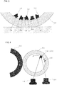
Fig. 3 is a schematic diagram illustrating a contact state of the sensor case having come off from the base with respect to an inner surface of a tire. -
Fig. 4 is a diagram illustrating a test method (drum test) for grasping affect on the inner surface of the tire due to drop-off of the sensor case. -
Figs. 5(a) and 5(b) are diagrams illustrating results of the drum test. -
Figs. 6(a) and 6(b) are diagrams illustrating another example of the sensor case according to the present invention. -
Figs. 7(a) to 7(d) are diagrams illustrating another example of the sensor case according to the present invention. -
Fig. 8 is a schematic diagram illustrating a drop-off state of the sensor case. - Figs. 98(a) and
9(b) are diagrams showing examples of damage on the inner surface of the tire due to drop-off of the sensor case. - An embodiment of the present invention is described with reference to the attached drawings.
-
Fig. 1 illustrates asensor case 10 according to the present invention, andFig. 2 is a sectional view of the sensor case attached to a rubber base 20 (hereinafter referred to as a sensor case 10G with a rubber base). - The
sensor case 10 includes ahoused part 11 to be housed in therubber base 20, aholding part 12 formed so as to protrude from thehoused part 11, and asensor module 13. - The
sensor module 13 is configured by integrating asensor 14 for measuring a temperature, a pressure, a vibration and the like of the inside of a tire, apower generation element 15 as a power source and awireless device 16 for transmitting data detected by thesensor 14, and is built in at least one of thehoused part 11 and theholding part 12. - Hereinafter, it is assumed that a protruding direction of the
holding part 12 is an upper side, a direction opposed to the protruding direction is a lower side, and right-and-left direction in the figures is a width direction. The lower side is an inner surface (here, which is an inner liner 31) side of atire 30 when the sensor case 10G with the rubber base is attached. - The
sensor case 10 of the present example is so formed that a maximum width of thehoused part 11 is larger than a width of theholding part 12. Namely, thehoused part 11 corresponds to a lower side member and theholding part 12 corresponds to an upper side member of the present invention. - Hereinafter, it is assumed that an upper side surface of the
housed part 11 is anupper surface 11a, a lower side surface is abottom surface 11b of thehoused part 11, an upper surface of theholding part 12 is atop surface 12a and a lower surface of theholding part 12 is a connectingsurface 12b. - The
housed part 11, which is a lower side member, is configured, as illustrated in the right side figure ofFig. 1 , by a rotational body formed by rotating a half of a rounded rectangle (truck-shaped figure) about a center axis J. Accordingly, theupper surface 11a and thebottom surface 11b of thehoused part 11 become plane surfaces and theside surface 11c becomes a curved surface convex outwardly in the width direction. The shape of theside surface 11c is a half circle when cut on a plane passing the center axis J. - That is, with respect to the
housed part 11 of thesensor case 10, theside surface 11c and theupper surface 11a of the housedpart 11 are connected by acurved surface 11p being in contact with theupper surface 11a, theside surface 11c and thebottom surface 11b are connected by acurved surface 11q being in contact with thebottom surface 11b, and a maximum width part of theside surface 11c is formed by acurved surface 11r convex outwardly in the width direction. - On the other hand, with respect to the
holding part 12, which is the upper side member, an upper left part of a rectangle-shape figure is formed by a rotational body formed by rotating, about the center axis J, an arc shaped figure whose circumferential angle is 90 degrees. Accordingly, thetop surface 12a and the connectingsurface 12b of theholding part 12 become plane surfaces, and thecolumnar side surface 12c and thetop surface 12a are connected by the curved surface formed by rotating, about the center axis J, an arc which is a curved surface being in contact with thetop surface 12a and whose circumferential angle is 90 degrees. - The
rubber base 20, which is a rubber-made member, has anopening part 21 for inserting thehoused part 11 of thesensor case 10 and a housingconcave portion 22 for housing thehoused part 11 of thesensor case 10. Therubber base 20 further includes aplanar bottom part 23 which is adhered to an inner liner 31 of the tire 30and asidewall part 24 which connects thebottom part 23 and theopening part 21. - The
sidewall part 24 is a tubular member having a concave part of a rotational body shape whose sectional shape is rounded rectangle when cut at a plane parallel to the center axis J. An outer circumferential surface of thesidewall part 24 is formed so as to go away from the center axis J as it goes toward abottom part 23 side. An inner wall of thesidewall part 24 and an inner wall of thebottom part 23 form a housingconcave part 22 having the same shape as the housedpart 11 of thesensor case 10. - Since the
sensor case 10 of the present invention has the above-described shape, even when thesensor case 10 comes off from thebase 20 due to a crack generated between thebottom part 23 and theside wall part 24 of thebase 20 and rolls on the inner surface of thetire 30, because, as illustrated inFig. 3 , parts (11p, 11q, 11r, 12p) that contact with the surface of the inner liner 31, which is the inner surface of thetire 30, are all curved surfaces, no scratch mark is made on the inner surface of thetire 30 or the inner surface of thetire 30 is not scraped. Namely, with the use of thesensor case 10 of the present invention, it is possible to prevent the inner surface of thetire 30 from being damaged even when thesensor case 10 comes off from the base and rolls on the inner surface of thetire 30. - Even when the
sensor case 10 comes off, together with thebase 20, from the inner surface of the tire and rolls on the inner surface of the tire, the inner surface of thetire 30 is not damaged because theholding part 12 exposed from thebase 20 is connected at thecolumnar side surface 12c and thetop surface 12a by thecurved surface 12p being in contact with thetop surface 12a. - As illustrated in
Fig. 4 , after thebase 20 having thesensor case 10 of the present invention inserted therein was fixed on the inner surface of the tire by an adhesion agent, a drum test was conducted by rotating thetire 30 at a rotational speed of 60 [km/h] while pressing thetire 30 onto adrum 40 to check a surface condition of an inner liner after running of 5000 [km]. - The test was conducted with a tire size of 195/65R15, an inner pressure of 230 [kPa] and a load of 615 [kg].
- The
sensor case 10 of the present invention is one as illustrated inFig. 1 . For comparison, the same test was conducted for asensor case 50 whoseholding part 12 was made to be a columnar shape (comparative example). - The test was conducted in a state that the
sensor case base 20 under such a condition that a weight of the sensor case was 20g and a height of thesidewall part 24 of thebase 20 was made half, and so on. A cut may be made in advance between thebottom part 23 and thesidewall part 24 of thebase 20 so as to make thesensor cases base 20. - Test results are shown in
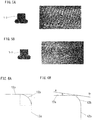
Figs 5(a) and 5(b) . -
Fig. 5(a) shows a test result of thesensor case 10 of the present invention andFig. 5(b) shows a test result of thesensor 50 whoseholding part 12 was made to be columnar shape. - In the
sensor case 10 of the present invention shown inFig. 5(a) , scrape and scratch were not found on the inner liner surface, whereas, in the comparative example shown inFig. 5(b) , not only a ridge part of the inner liner was scraped in a rotation direction, but also a scratch mark was found in a part where scrape was not found. - From the above, it has been confirmed that, if the part of the sensor case being in contact with the inner surface of the tire was made to be a curved surface, it is possible to prevent the inner surface of the tire from being damaged even if the sensor case comes off from the base and rolls on the inner surface of the tire.
- The embodiment and example of the present invention have been described, however, it should be noted that the technical scope of the present invention is not limited to the scope described in the embodiment. It is apparent for a person with ordinary skill in the art that various changes and modifications may be made to the embodiment described above. It is also apparent from the scope of the claims that such changes and modifications may be included in the technical scope of the present invention.
- For example, in the above-described embodiment, a case in which the
sensor case 10 is attached to thebase 20 has been described, however, even in a case in which thesensor case 10 is attached on the inner surface of the tire, if thesensor case 10 is of the embodiment of the present invention, it is needless to say that the inner surface of the tire is not damaged even if thesensor case 10 comes off from the inner surface of the tire and rolls on the inner surface of the tire. - In the above-described embodiment, as illustrated in
Fig. 6(a) , theside surface 12c and thetop surface 12a of theholding part 12 are connected by thecurved surface 12p being in contact with theside surface 12c and thetop surface 12a and having an arc-shaped section with a circumferential angle of 90 degrees. However, as illustrated inFig. 6(b) , a gradient of tangent A at a connecting point with thetop surface 12a of thecurved surface 12p may not completely coincide with a gradient of tangent B at a connecting point with thecurved surface 12p of thetop surface 12a, but it is sufficient that an angle made between the two tangents A and B is within a range from 0 degrees to 15 degrees. - Furthermore, in the above-described embodiment, the
holding part 12, which is the upper side member, is made to be columnar shape and thecolumnar side surface 12c and thetop surface 12a are connected by the curved surface, however, as illustrated inFigs. 7(a) and 7(b) , thesensor case 10 may be further small-sized if theholding part 12 is made to be a part of a sphere. - Furthermore, as illustrated in
Figs. 7(c) and 7(d) , the sensor case may be further holdable if the upper side member is made to be a sphere, or equal to or greater than 2/3 of a spheroid. - The embodiment of the present invention has been described, however, the present invention may be summarized as follows. That is, the present invention relates to a sensor case with a sensor housed therein for obtaining information on a tire, the sensor case including: a lower side member having a bottom surface to be attached on an inner surface of the tire or to a base for mounting the sensor case on the inner surface of the tire; and an upper side member protruding from a surface opposite to the bottom surface of the lower side member to a side opposite to the bottom surface, in which a side surface of the lower side member is formed of a curved surface convex outwardly in a width direction, and a side surface of the upper side member and a top surface, which is a surface opposite to the bottom surface of the upper side member, are connected by a curved surface being in contact with the top surface.
- As such, since the part of the sensor case, which contacts with the inner surface of the tire when the sensor case comes off form the inner surface of the tire or from the base and rolls on the inner surface of the tire, is made to be a curved surface, it is possible to prevent the inner surface of the tire from being damaged. Further, the inner surface of the tire is not damaged for the reason similar to the reason described above, even if the sensor case comes off, together with the base, from the inner surface of the tire and rolls on the inner surface of the tire.
- Further, since the side surface and the bottom surface of the lower member are connected by a curved surface being in contact with the bottom surface, and the side surface of the lower member and an upper surface, which is the surface opposite to the bottom surface of the lower member, are connected by the curved surface being in contact with the upper surface, even in a case in which the sensor case collides with the inner surface of the tire, it is possible to present the inner surface of the tire from being damaged.
- Furthermore, since the upper side member is a part of a sphere or a part of a spheroid, the sensor case can be small sized. If the upper side member is made to be a sphere, or equal to or greater than 2/3 of a spheroid, the sensor case may be made further holdable.
-
- 10: sensor case
- 20: rubber base
- 10G: sensor case with rubber base
- 11: housed part
- 12: holding part
- 13: sensor module
- 14: sensor
- 15: power generation element
- 16: wireless device
- 30: tire
- 31: inner liner
Claims (3)
- A sensor case with a sensor housed therein for obtaining information on a tire, the sensor case comprising:a lower side member having a bottom surface to be attached on an inner surface of the tire or to a base for mounting the sensor case on the inner surface of the tire; andan upper side member protruding from a surface opposite to the bottom surface of the lower side member to a side opposite to the bottom surface and having a width smaller than a width of the lower side member, whereina side surface of the lower side member is formed of a curved surface convex outwardly in a width direction, anda side surface of the upper side member and a top surface of the upper side member, which is a surface opposite to the bottom surface, are connected by a curved surface being in contact with the top surface.
- The sensor case according to Claim 1, wherein
the side surface and the bottom surface of the lower side member are connected by a curved surface being in contact with the bottom surface, and
the side surface of the lower side member and an upper surface of the lower side member, which is a surface opposite to the bottom surface of the lower side member, are connected by a curved surface being in contact with the upper surface. - The sensor case according to Claim 1 or Claim 2, wherein the upper side member is a part of a sphere or a part of a spheroid.
Applications Claiming Priority (2)
| Application Number | Priority Date | Filing Date | Title |
|---|---|---|---|
| JP2016150531A JP6783088B2 (en) | 2016-07-29 | 2016-07-29 | Sensor case |
| PCT/JP2017/027554 WO2018021564A1 (en) | 2016-07-29 | 2017-07-28 | Sensor case |
Publications (3)
| Publication Number | Publication Date |
|---|---|
| EP3492285A4 EP3492285A4 (en) | 2019-06-05 |
| EP3492285A1 true EP3492285A1 (en) | 2019-06-05 |
| EP3492285B1 EP3492285B1 (en) | 2022-09-07 |
Family
ID=61016285
Family Applications (1)
| Application Number | Title | Priority Date | Filing Date |
|---|---|---|---|
| EP17834566.6A Active EP3492285B1 (en) | 2016-07-29 | 2017-07-28 | Sensor case |
Country Status (5)
| Country | Link |
|---|---|
| US (1) | US10779424B2 (en) |
| EP (1) | EP3492285B1 (en) |
| JP (1) | JP6783088B2 (en) |
| CN (1) | CN109641491B (en) |
| WO (1) | WO2018021564A1 (en) |
Families Citing this family (3)
| Publication number | Priority date | Publication date | Assignee | Title |
|---|---|---|---|---|
| US11835421B2 (en) * | 2019-10-31 | 2023-12-05 | Keith George Ferry | Sensor assemblies and systems for monitoring a dynamic object |
| US12344051B2 (en) | 2019-10-31 | 2025-07-01 | Cerebrum Sensor Technologies, Inc. | Sensor assemblies and systems for monitoring a dynamic object |
| CN115703309A (en) * | 2021-08-06 | 2023-02-17 | 建大工业股份有限公司 | tires equipped with sensors |
Family Cites Families (29)
| Publication number | Priority date | Publication date | Assignee | Title |
|---|---|---|---|---|
| FR2492742A1 (en) * | 1980-08-05 | 1982-04-30 | Dba | PRESSURE SENSOR FOR TIRES |
| DE3735956A1 (en) * | 1987-10-23 | 1989-05-03 | Kopp Gmbh & Co Kg Heinrich | Optical alignment means for infrared movement detectors (proximity detectors), punctiform lamps and the like |
| US6255940B1 (en) | 1999-10-01 | 2001-07-03 | The Goodyear Tire & Rubber Company | Apparatus for monitoring a condition of a tire |
| DE10243441B4 (en) | 2002-09-18 | 2004-12-30 | Continental Aktiengesellschaft | Tire transponder |
| US7030743B2 (en) * | 2002-11-05 | 2006-04-18 | Tagg Technology Corp. | Tire pressure indicator providing a visual indication of tire pressure |
| US6854324B2 (en) | 2002-12-20 | 2005-02-15 | The Goodyear Tire & Rubber Company | Tire monitoring apparatus |
| JP2004330842A (en) * | 2003-05-06 | 2004-11-25 | Yokohama Rubber Co Ltd:The | Sensor device for mounting tire and tire mounted with sensor |
| FR2861650B1 (en) * | 2003-11-05 | 2006-01-06 | Michelin Soc Tech | DEVICE FOR FIXING A SURVEILLANCE MODULE ON THE INNER SURFACE OF A TIRE |
| JP2005348032A (en) | 2004-06-02 | 2005-12-15 | Yokohama Rubber Co Ltd:The | On-vehicle communication antenna |
| DE202005005144U1 (en) * | 2005-03-31 | 2005-06-23 | Stahlgruber Otto Gruber Gmbh & Co Kg | Holder for fixing an electronic component to a rubber article |
| JP2007126026A (en) | 2005-11-04 | 2007-05-24 | Alps Electric Co Ltd | Antenna device |
| EP2015942B1 (en) * | 2006-04-26 | 2016-04-06 | Pirelli Tyre S.p.A. | A tyre comprising an electronic unit |
| CA2746161C (en) * | 2008-12-09 | 2015-02-03 | Bridgestone Corporation | Device for acquiring information regarding the inside of a tire |
| CN103038072B (en) | 2010-04-09 | 2016-08-10 | 倍耐力轮胎股份公司 | tire sensor device |
| DE102010023247A1 (en) * | 2010-06-09 | 2011-12-15 | Johnson Controls Gmbh | Equipment part with a luminous surface |
| CN202016376U (en) * | 2011-04-08 | 2011-10-26 | 包头市国领新技术有限公司 | Tire pressure detection device |
| US8596117B2 (en) | 2011-10-03 | 2013-12-03 | Bridgestone Americas Tire Operations, Llc | Attachment patch for mounting various devices |
| CN102445300B (en) * | 2011-10-09 | 2013-08-14 | 北京化工大学 | Dynamic grounding pressure test device |
| CN102514455B (en) * | 2011-10-31 | 2014-02-26 | 香港应用科技研究院有限公司 | Tire pressure monitoring system without assembly |
| ITMI20112427A1 (en) * | 2011-12-29 | 2013-06-30 | Pirelli | MONITORING DEVICE FOR TIRES FOR WHEELS OF VEHICLES, TIRES FOR WHEELS OF VEHICLES PROVIDED WITH SUCH A MONITORING DEVICE, AND A METHOD FOR INSTALLING AN ELECTRONIC UNIT IN THAT TIRE |
| JP5837851B2 (en) | 2012-04-24 | 2015-12-24 | 株式会社ブリヂストン | Electronic component mounting structure on the inner surface of a pneumatic tire |
| CN202764617U (en) * | 2012-09-11 | 2013-03-06 | 上海航盛实业有限公司 | Base structure of after-loading tire pressure monitoring system device |
| US8939020B2 (en) * | 2012-12-05 | 2015-01-27 | Caterpillar Inc. | Spherical monitoring device for pneumatic tires |
| US9205714B2 (en) | 2012-12-20 | 2015-12-08 | The Goodyear Tire & Rubber Company | Compact valve system for self-inflating tire |
| CN105531126B (en) | 2013-08-05 | 2018-04-06 | 倍耐力轮胎股份公司 | Monitoring device for monitoring tires for vehicle wheels, tire provided with said monitoring device, and method for installing electronic unit in tire |
| JP6382529B2 (en) * | 2014-02-27 | 2018-08-29 | 株式会社ブリヂストン | Functional component mounting base and tire |
| DE102014213060A1 (en) * | 2014-07-04 | 2016-01-07 | Continental Automotive France | Method for mounting tire modules on the inside of tires of vehicle tires |
| CN204623029U (en) * | 2015-01-15 | 2015-09-09 | 深圳市豪恩汽车电子装备有限公司 | Built-in tyre pressure sensor |
| KR101760872B1 (en) * | 2015-08-24 | 2017-07-24 | 한국타이어 주식회사 | Pneumatic tire comprising sensor patch and method for manufacturing the same |
-
2016
- 2016-07-29 JP JP2016150531A patent/JP6783088B2/en not_active Expired - Fee Related
-
2017
- 2017-07-28 US US16/316,738 patent/US10779424B2/en active Active
- 2017-07-28 EP EP17834566.6A patent/EP3492285B1/en active Active
- 2017-07-28 WO PCT/JP2017/027554 patent/WO2018021564A1/en not_active Ceased
- 2017-07-28 CN CN201780047284.1A patent/CN109641491B/en not_active Expired - Fee Related
Also Published As
| Publication number | Publication date |
|---|---|
| JP2018016278A (en) | 2018-02-01 |
| CN109641491B (en) | 2021-04-20 |
| WO2018021564A1 (en) | 2018-02-01 |
| JP6783088B2 (en) | 2020-11-11 |
| EP3492285B1 (en) | 2022-09-07 |
| EP3492285A4 (en) | 2019-06-05 |
| US20190307003A1 (en) | 2019-10-03 |
| US10779424B2 (en) | 2020-09-15 |
| CN109641491A (en) | 2019-04-16 |
Similar Documents
| Publication | Publication Date | Title |
|---|---|---|
| EP3492285B1 (en) | Sensor case | |
| EP3620313B1 (en) | Fitting structure between functional component accomodation case and rubber base | |
| US9463673B2 (en) | Tire positioning method and tire positioning system | |
| CN101460320B (en) | A tyre comprising an electronic unit and a method of installing said electronic unit into said tyre | |
| US20200055353A1 (en) | Functional component attachment base | |
| JP2008049999A (en) | Aircraft tire condition monitoring system and method | |
| JP5546808B2 (en) | Flat battery mounting method and device mounted on rotating part | |
| US20200055354A1 (en) | Device for attaching an electronic member to a pneumatic tire | |
| EP1321314A2 (en) | Transmitter of tire condition monitoring apparatus | |
| KR100454223B1 (en) | Transmitter Of Tire Condition Monitoring Apparatus | |
| CN105555553B (en) | Pneumatic tire | |
| EP3450222B1 (en) | Tire condition detecting apparatus, clamp-in valve and tire valve unit | |
| JP2026503389A (en) | Device for fixing electronic components to tire casing | |
| CN115195360A (en) | Tire pressure detection device | |
| JP5816709B2 (en) | Device attached to rotating parts | |
| JP2017165271A (en) | Functional component device | |
| CN204605422U (en) | Tire pressure monitoring sensor | |
| JP2025542588A (en) | Device for fixing electronic components to tire casing | |
| KR20250120296A (en) | Device for attaching electronic components to a tire casing | |
| JP2019142380A (en) | Electronic device and tire | |
| JP5548402B2 (en) | Flat battery mounting method and tire mounting apparatus | |
| JP2019137217A (en) | Electronic device and tire | |
| JP2019093832A (en) | Function component mounting pedestal and tire | |
| CN113784852A (en) | Inflation valve with bulb having a double symmetrical cavity for the passage of a tubular core | |
| JP2018065493A (en) | Tire information acquisition device with rubber pedestal |
Legal Events
| Date | Code | Title | Description |
|---|---|---|---|
| STAA | Information on the status of an ep patent application or granted ep patent |
Free format text: STATUS: THE INTERNATIONAL PUBLICATION HAS BEEN MADE |
|
| PUAI | Public reference made under article 153(3) epc to a published international application that has entered the european phase |
Free format text: ORIGINAL CODE: 0009012 |
|
| STAA | Information on the status of an ep patent application or granted ep patent |
Free format text: STATUS: REQUEST FOR EXAMINATION WAS MADE |
|
| 17P | Request for examination filed |
Effective date: 20190115 |
|
| A4 | Supplementary search report drawn up and despatched |
Effective date: 20190402 |
|
| AK | Designated contracting states |
Kind code of ref document: A1 Designated state(s): AL AT BE BG CH CY CZ DE DK EE ES FI FR GB GR HR HU IE IS IT LI LT LU LV MC MK MT NL NO PL PT RO RS SE SI SK SM TR |
|
| AX | Request for extension of the european patent |
Extension state: BA ME |
|
| DAV | Request for validation of the european patent (deleted) | ||
| DAX | Request for extension of the european patent (deleted) | ||
| STAA | Information on the status of an ep patent application or granted ep patent |
Free format text: STATUS: EXAMINATION IS IN PROGRESS |
|
| 17Q | First examination report despatched |
Effective date: 20210901 |
|
| GRAP | Despatch of communication of intention to grant a patent |
Free format text: ORIGINAL CODE: EPIDOSNIGR1 |
|
| STAA | Information on the status of an ep patent application or granted ep patent |
Free format text: STATUS: GRANT OF PATENT IS INTENDED |
|
| INTG | Intention to grant announced |
Effective date: 20220517 |
|
| GRAS | Grant fee paid |
Free format text: ORIGINAL CODE: EPIDOSNIGR3 |
|
| GRAA | (expected) grant |
Free format text: ORIGINAL CODE: 0009210 |
|
| STAA | Information on the status of an ep patent application or granted ep patent |
Free format text: STATUS: THE PATENT HAS BEEN GRANTED |
|
| AK | Designated contracting states |
Kind code of ref document: B1 Designated state(s): AL AT BE BG CH CY CZ DE DK EE ES FI FR GB GR HR HU IE IS IT LI LT LU LV MC MK MT NL NO PL PT RO RS SE SI SK SM TR |
|
| REG | Reference to a national code |
Ref country code: GB Ref legal event code: FG4D |
|
| REG | Reference to a national code |
Ref country code: CH Ref legal event code: EP Ref country code: AT Ref legal event code: REF Ref document number: 1516733 Country of ref document: AT Kind code of ref document: T Effective date: 20220915 |
|
| REG | Reference to a national code |
Ref country code: IE Ref legal event code: FG4D |
|
| REG | Reference to a national code |
Ref country code: DE Ref legal event code: R096 Ref document number: 602017061623 Country of ref document: DE |
|
| REG | Reference to a national code |
Ref country code: LT Ref legal event code: MG9D |
|
| REG | Reference to a national code |
Ref country code: NL Ref legal event code: MP Effective date: 20220907 |
|
| PG25 | Lapsed in a contracting state [announced via postgrant information from national office to epo] |
Ref country code: SE Free format text: LAPSE BECAUSE OF FAILURE TO SUBMIT A TRANSLATION OF THE DESCRIPTION OR TO PAY THE FEE WITHIN THE PRESCRIBED TIME-LIMIT Effective date: 20220907 Ref country code: RS Free format text: LAPSE BECAUSE OF FAILURE TO SUBMIT A TRANSLATION OF THE DESCRIPTION OR TO PAY THE FEE WITHIN THE PRESCRIBED TIME-LIMIT Effective date: 20220907 Ref country code: NO Free format text: LAPSE BECAUSE OF FAILURE TO SUBMIT A TRANSLATION OF THE DESCRIPTION OR TO PAY THE FEE WITHIN THE PRESCRIBED TIME-LIMIT Effective date: 20221207 Ref country code: LV Free format text: LAPSE BECAUSE OF FAILURE TO SUBMIT A TRANSLATION OF THE DESCRIPTION OR TO PAY THE FEE WITHIN THE PRESCRIBED TIME-LIMIT Effective date: 20220907 Ref country code: LT Free format text: LAPSE BECAUSE OF FAILURE TO SUBMIT A TRANSLATION OF THE DESCRIPTION OR TO PAY THE FEE WITHIN THE PRESCRIBED TIME-LIMIT Effective date: 20220907 Ref country code: FI Free format text: LAPSE BECAUSE OF FAILURE TO SUBMIT A TRANSLATION OF THE DESCRIPTION OR TO PAY THE FEE WITHIN THE PRESCRIBED TIME-LIMIT Effective date: 20220907 |
|
| REG | Reference to a national code |
Ref country code: AT Ref legal event code: MK05 Ref document number: 1516733 Country of ref document: AT Kind code of ref document: T Effective date: 20220907 |
|
| PG25 | Lapsed in a contracting state [announced via postgrant information from national office to epo] |
Ref country code: HR Free format text: LAPSE BECAUSE OF FAILURE TO SUBMIT A TRANSLATION OF THE DESCRIPTION OR TO PAY THE FEE WITHIN THE PRESCRIBED TIME-LIMIT Effective date: 20220907 Ref country code: GR Free format text: LAPSE BECAUSE OF FAILURE TO SUBMIT A TRANSLATION OF THE DESCRIPTION OR TO PAY THE FEE WITHIN THE PRESCRIBED TIME-LIMIT Effective date: 20221208 |
|
| PG25 | Lapsed in a contracting state [announced via postgrant information from national office to epo] |
Ref country code: SM Free format text: LAPSE BECAUSE OF FAILURE TO SUBMIT A TRANSLATION OF THE DESCRIPTION OR TO PAY THE FEE WITHIN THE PRESCRIBED TIME-LIMIT Effective date: 20220907 Ref country code: RO Free format text: LAPSE BECAUSE OF FAILURE TO SUBMIT A TRANSLATION OF THE DESCRIPTION OR TO PAY THE FEE WITHIN THE PRESCRIBED TIME-LIMIT Effective date: 20220907 Ref country code: PT Free format text: LAPSE BECAUSE OF FAILURE TO SUBMIT A TRANSLATION OF THE DESCRIPTION OR TO PAY THE FEE WITHIN THE PRESCRIBED TIME-LIMIT Effective date: 20230109 Ref country code: ES Free format text: LAPSE BECAUSE OF FAILURE TO SUBMIT A TRANSLATION OF THE DESCRIPTION OR TO PAY THE FEE WITHIN THE PRESCRIBED TIME-LIMIT Effective date: 20220907 Ref country code: CZ Free format text: LAPSE BECAUSE OF FAILURE TO SUBMIT A TRANSLATION OF THE DESCRIPTION OR TO PAY THE FEE WITHIN THE PRESCRIBED TIME-LIMIT Effective date: 20220907 Ref country code: AT Free format text: LAPSE BECAUSE OF FAILURE TO SUBMIT A TRANSLATION OF THE DESCRIPTION OR TO PAY THE FEE WITHIN THE PRESCRIBED TIME-LIMIT Effective date: 20220907 |
|
| PG25 | Lapsed in a contracting state [announced via postgrant information from national office to epo] |
Ref country code: SK Free format text: LAPSE BECAUSE OF FAILURE TO SUBMIT A TRANSLATION OF THE DESCRIPTION OR TO PAY THE FEE WITHIN THE PRESCRIBED TIME-LIMIT Effective date: 20220907 Ref country code: PL Free format text: LAPSE BECAUSE OF FAILURE TO SUBMIT A TRANSLATION OF THE DESCRIPTION OR TO PAY THE FEE WITHIN THE PRESCRIBED TIME-LIMIT Effective date: 20220907 Ref country code: IS Free format text: LAPSE BECAUSE OF FAILURE TO SUBMIT A TRANSLATION OF THE DESCRIPTION OR TO PAY THE FEE WITHIN THE PRESCRIBED TIME-LIMIT Effective date: 20230107 Ref country code: EE Free format text: LAPSE BECAUSE OF FAILURE TO SUBMIT A TRANSLATION OF THE DESCRIPTION OR TO PAY THE FEE WITHIN THE PRESCRIBED TIME-LIMIT Effective date: 20220907 |
|
| REG | Reference to a national code |
Ref country code: DE Ref legal event code: R097 Ref document number: 602017061623 Country of ref document: DE |
|
| PG25 | Lapsed in a contracting state [announced via postgrant information from national office to epo] |
Ref country code: NL Free format text: LAPSE BECAUSE OF FAILURE TO SUBMIT A TRANSLATION OF THE DESCRIPTION OR TO PAY THE FEE WITHIN THE PRESCRIBED TIME-LIMIT Effective date: 20220907 Ref country code: AL Free format text: LAPSE BECAUSE OF FAILURE TO SUBMIT A TRANSLATION OF THE DESCRIPTION OR TO PAY THE FEE WITHIN THE PRESCRIBED TIME-LIMIT Effective date: 20220907 |
|
| P01 | Opt-out of the competence of the unified patent court (upc) registered |
Effective date: 20230531 |
|
| PLBE | No opposition filed within time limit |
Free format text: ORIGINAL CODE: 0009261 |
|
| STAA | Information on the status of an ep patent application or granted ep patent |
Free format text: STATUS: NO OPPOSITION FILED WITHIN TIME LIMIT |
|
| PG25 | Lapsed in a contracting state [announced via postgrant information from national office to epo] |
Ref country code: DK Free format text: LAPSE BECAUSE OF FAILURE TO SUBMIT A TRANSLATION OF THE DESCRIPTION OR TO PAY THE FEE WITHIN THE PRESCRIBED TIME-LIMIT Effective date: 20220907 |
|
| 26N | No opposition filed |
Effective date: 20230608 |
|
| PG25 | Lapsed in a contracting state [announced via postgrant information from national office to epo] |
Ref country code: SI Free format text: LAPSE BECAUSE OF FAILURE TO SUBMIT A TRANSLATION OF THE DESCRIPTION OR TO PAY THE FEE WITHIN THE PRESCRIBED TIME-LIMIT Effective date: 20220907 |
|
| PGFP | Annual fee paid to national office [announced via postgrant information from national office to epo] |
Ref country code: FR Payment date: 20230726 Year of fee payment: 7 Ref country code: DE Payment date: 20230719 Year of fee payment: 7 |
|
| PG25 | Lapsed in a contracting state [announced via postgrant information from national office to epo] |
Ref country code: MC Free format text: LAPSE BECAUSE OF FAILURE TO SUBMIT A TRANSLATION OF THE DESCRIPTION OR TO PAY THE FEE WITHIN THE PRESCRIBED TIME-LIMIT Effective date: 20220907 |
|
| PG25 | Lapsed in a contracting state [announced via postgrant information from national office to epo] |
Ref country code: MC Free format text: LAPSE BECAUSE OF FAILURE TO SUBMIT A TRANSLATION OF THE DESCRIPTION OR TO PAY THE FEE WITHIN THE PRESCRIBED TIME-LIMIT Effective date: 20220907 |
|
| REG | Reference to a national code |
Ref country code: CH Ref legal event code: PL |
|
| REG | Reference to a national code |
Ref country code: BE Ref legal event code: MM Effective date: 20230731 |
|
| PG25 | Lapsed in a contracting state [announced via postgrant information from national office to epo] |
Ref country code: LU Free format text: LAPSE BECAUSE OF NON-PAYMENT OF DUE FEES Effective date: 20230728 |
|
| GBPC | Gb: european patent ceased through non-payment of renewal fee |
Effective date: 20230728 |
|
| PG25 | Lapsed in a contracting state [announced via postgrant information from national office to epo] |
Ref country code: LU Free format text: LAPSE BECAUSE OF NON-PAYMENT OF DUE FEES Effective date: 20230728 |
|
| REG | Reference to a national code |
Ref country code: IE Ref legal event code: MM4A |
|
| PG25 | Lapsed in a contracting state [announced via postgrant information from national office to epo] |
Ref country code: CH Free format text: LAPSE BECAUSE OF NON-PAYMENT OF DUE FEES Effective date: 20230731 Ref country code: GB Free format text: LAPSE BECAUSE OF NON-PAYMENT OF DUE FEES Effective date: 20230728 |
|
| PG25 | Lapsed in a contracting state [announced via postgrant information from national office to epo] |
Ref country code: IT Free format text: LAPSE BECAUSE OF FAILURE TO SUBMIT A TRANSLATION OF THE DESCRIPTION OR TO PAY THE FEE WITHIN THE PRESCRIBED TIME-LIMIT Effective date: 20220907 Ref country code: BE Free format text: LAPSE BECAUSE OF NON-PAYMENT OF DUE FEES Effective date: 20230731 |
|
| PG25 | Lapsed in a contracting state [announced via postgrant information from national office to epo] |
Ref country code: IE Free format text: LAPSE BECAUSE OF NON-PAYMENT OF DUE FEES Effective date: 20230728 |
|
| PG25 | Lapsed in a contracting state [announced via postgrant information from national office to epo] |
Ref country code: IE Free format text: LAPSE BECAUSE OF NON-PAYMENT OF DUE FEES Effective date: 20230728 |
|
| PG25 | Lapsed in a contracting state [announced via postgrant information from national office to epo] |
Ref country code: BG Free format text: LAPSE BECAUSE OF FAILURE TO SUBMIT A TRANSLATION OF THE DESCRIPTION OR TO PAY THE FEE WITHIN THE PRESCRIBED TIME-LIMIT Effective date: 20220907 |
|
| PG25 | Lapsed in a contracting state [announced via postgrant information from national office to epo] |
Ref country code: BG Free format text: LAPSE BECAUSE OF FAILURE TO SUBMIT A TRANSLATION OF THE DESCRIPTION OR TO PAY THE FEE WITHIN THE PRESCRIBED TIME-LIMIT Effective date: 20220907 |
|
| REG | Reference to a national code |
Ref country code: DE Ref legal event code: R119 Ref document number: 602017061623 Country of ref document: DE |
|
| PG25 | Lapsed in a contracting state [announced via postgrant information from national office to epo] |
Ref country code: DE Free format text: LAPSE BECAUSE OF NON-PAYMENT OF DUE FEES Effective date: 20250201 |
|
| PG25 | Lapsed in a contracting state [announced via postgrant information from national office to epo] |
Ref country code: FR Free format text: LAPSE BECAUSE OF NON-PAYMENT OF DUE FEES Effective date: 20240731 |
|
| PG25 | Lapsed in a contracting state [announced via postgrant information from national office to epo] |
Ref country code: CY Free format text: LAPSE BECAUSE OF FAILURE TO SUBMIT A TRANSLATION OF THE DESCRIPTION OR TO PAY THE FEE WITHIN THE PRESCRIBED TIME-LIMIT; INVALID AB INITIO Effective date: 20170728 |
|
| PG25 | Lapsed in a contracting state [announced via postgrant information from national office to epo] |
Ref country code: HU Free format text: LAPSE BECAUSE OF FAILURE TO SUBMIT A TRANSLATION OF THE DESCRIPTION OR TO PAY THE FEE WITHIN THE PRESCRIBED TIME-LIMIT; INVALID AB INITIO Effective date: 20170728 |
|
| PG25 | Lapsed in a contracting state [announced via postgrant information from national office to epo] |
Ref country code: TR Free format text: LAPSE BECAUSE OF FAILURE TO SUBMIT A TRANSLATION OF THE DESCRIPTION OR TO PAY THE FEE WITHIN THE PRESCRIBED TIME-LIMIT Effective date: 20220907 |