EP3492227B1 - Razor cartridge - Google Patents
Razor cartridge Download PDFInfo
- Publication number
- EP3492227B1 EP3492227B1 EP18209138.9A EP18209138A EP3492227B1 EP 3492227 B1 EP3492227 B1 EP 3492227B1 EP 18209138 A EP18209138 A EP 18209138A EP 3492227 B1 EP3492227 B1 EP 3492227B1
- Authority
- EP
- European Patent Office
- Prior art keywords
- razor
- blade
- seating
- seating protrusion
- razor cartridge
- Prior art date
- Legal status (The legal status is an assumption and is not a legal conclusion. Google has not performed a legal analysis and makes no representation as to the accuracy of the status listed.)
- Active
Links
- 238000005520 cutting process Methods 0.000 claims description 36
- 229910000831 Steel Inorganic materials 0.000 claims description 13
- 239000010959 steel Substances 0.000 claims description 13
- 239000002184 metal Substances 0.000 claims description 10
- 238000003825 pressing Methods 0.000 claims description 8
- 238000003780 insertion Methods 0.000 claims description 2
- 230000037431 insertion Effects 0.000 claims description 2
- 230000008878 coupling Effects 0.000 description 12
- 238000010168 coupling process Methods 0.000 description 12
- 238000005859 coupling reaction Methods 0.000 description 12
- 238000001746 injection moulding Methods 0.000 description 8
- 238000004519 manufacturing process Methods 0.000 description 5
- 238000005461 lubrication Methods 0.000 description 4
- 238000000034 method Methods 0.000 description 4
- 238000002347 injection Methods 0.000 description 3
- 239000007924 injection Substances 0.000 description 3
- 238000005452 bending Methods 0.000 description 2
- 230000001815 facial effect Effects 0.000 description 2
- LQIAZOCLNBBZQK-UHFFFAOYSA-N 1-(1,2-Diphosphanylethyl)pyrrolidin-2-one Chemical compound PCC(P)N1CCCC1=O LQIAZOCLNBBZQK-UHFFFAOYSA-N 0.000 description 1
- 239000000919 ceramic Substances 0.000 description 1
- 230000003247 decreasing effect Effects 0.000 description 1
- 230000007547 defect Effects 0.000 description 1
- 239000007769 metal material Substances 0.000 description 1
- 230000007935 neutral effect Effects 0.000 description 1
- 239000010802 sludge Substances 0.000 description 1
- 229910001220 stainless steel Inorganic materials 0.000 description 1
- 239000010935 stainless steel Substances 0.000 description 1
Images


Classifications
-
- B—PERFORMING OPERATIONS; TRANSPORTING
- B26—HAND CUTTING TOOLS; CUTTING; SEVERING
- B26B—HAND-HELD CUTTING TOOLS NOT OTHERWISE PROVIDED FOR
- B26B21/00—Razors of the open or knife type; Safety razors or other shaving implements of the planing type; Hair-trimming devices involving a razor-blade; Equipment therefor
- B26B21/40—Details or accessories
- B26B21/4012—Housing details, e.g. for cartridges
- B26B21/4025—Cap elements
-
- B—PERFORMING OPERATIONS; TRANSPORTING
- B26—HAND CUTTING TOOLS; CUTTING; SEVERING
- B26B—HAND-HELD CUTTING TOOLS NOT OTHERWISE PROVIDED FOR
- B26B21/00—Razors of the open or knife type; Safety razors or other shaving implements of the planing type; Hair-trimming devices involving a razor-blade; Equipment therefor
- B26B21/08—Razors of the open or knife type; Safety razors or other shaving implements of the planing type; Hair-trimming devices involving a razor-blade; Equipment therefor involving changeable blades
- B26B21/14—Safety razors with one or more blades arranged transversely to the handle
- B26B21/22—Safety razors with one or more blades arranged transversely to the handle involving several blades to be used simultaneously
- B26B21/222—Safety razors with one or more blades arranged transversely to the handle involving several blades to be used simultaneously with the blades moulded into, or attached to, a changeable unit
-
- B—PERFORMING OPERATIONS; TRANSPORTING
- B26—HAND CUTTING TOOLS; CUTTING; SEVERING
- B26B—HAND-HELD CUTTING TOOLS NOT OTHERWISE PROVIDED FOR
- B26B21/00—Razors of the open or knife type; Safety razors or other shaving implements of the planing type; Hair-trimming devices involving a razor-blade; Equipment therefor
- B26B21/40—Details or accessories
- B26B21/4012—Housing details, e.g. for cartridges
- B26B21/4018—Guard elements
-
- B—PERFORMING OPERATIONS; TRANSPORTING
- B26—HAND CUTTING TOOLS; CUTTING; SEVERING
- B26B—HAND-HELD CUTTING TOOLS NOT OTHERWISE PROVIDED FOR
- B26B21/00—Razors of the open or knife type; Safety razors or other shaving implements of the planing type; Hair-trimming devices involving a razor-blade; Equipment therefor
- B26B21/40—Details or accessories
- B26B21/4012—Housing details, e.g. for cartridges
- B26B21/4031—Housing details, e.g. for cartridges characterised by special geometric shaving parameters, e.g. blade span or exposure
-
- B—PERFORMING OPERATIONS; TRANSPORTING
- B26—HAND CUTTING TOOLS; CUTTING; SEVERING
- B26B—HAND-HELD CUTTING TOOLS NOT OTHERWISE PROVIDED FOR
- B26B21/00—Razors of the open or knife type; Safety razors or other shaving implements of the planing type; Hair-trimming devices involving a razor-blade; Equipment therefor
- B26B21/40—Details or accessories
- B26B21/4068—Mounting devices; Manufacture of razors or cartridges
- B26B21/4075—Mounting devices
Definitions
- the present disclosure relates to a razor cartridge, and more particularly, to a razor cartridge and razor cartridge assembly having seating protrusions for more firmly seating a plurality of razor blades on a blade housing.
- a conventional razor which is known as a wet razor, includes a razor cartridge and a razor handle.
- the razor cartridge includes at least one blade disposed between a rear side of a guard bar and a front side of a cap and includes a blade housing for seating the blade.
- the razor cartridge is installed to be detachable from and pivotable on the razor handle so that the razor cartridge is able to pivot with respect to the razor handle, between a neutral position and a pivot position during use of the razor.
- pivoting motion is basically performed about a rotation axis that is parallel to a direction in which the razor blade is disposed on the blade housing. In this way, since the razor cartridge is detachably disposed on the razor handle, the user may remove a razor cartridge whose razor blade has become dull to some extent and mount a new razor cartridge on the razor handle for use when shaving afterwards.
- a razor having a corrugated protrusion has been proposed. According to this razor, sludge discharge is possible between blades, and the blades may be stably fixed.
- protrusions corresponding thereto have to be formed at narrow intervals, it may be difficult to form the protrusions by injection molding, and even if injection molding is possible, high accuracy is required in a subsequent assembling process due to the narrow intervals between the protrusions.
- a blade seating portion which has a structure capable of stably storing and keeping razor blades which have a narrow span therebetween or have a relatively thin base portion, and a razor cartridge including the same.
- aspects of the present disclosure provide a razor cartridge having seating protrusions for stably supporting blades on a blade housing.
- aspects of the present disclosure also provide a razor cartridge having a structure in which injection of a support member for supporting blades on a blade housing and a seating protrusion formed on the support member is facilitated.
- aspects of the present disclosure also provide a razor cartridge assembly including a connector that is able to be promptly and easily assembled to a blade housing.
- the present invention provides a razor cartridge as defined in the claims.
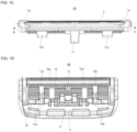
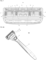
- FIG. 1A is a perspective view of a razor cartridge 10 according to an embodiment of the present disclosure
- FIG. 1B is a plan view of the razor cartridge 10
- FIG. 1C is a front view of the razor cartridge 10
- FIG. 1D is a bottom view of the razor cartridge 10.
- the razor cartridge 10 may include at least one razor blade 5 having a cutting edge, a blade housing 60 configured to accommodate the at least one razor blade 5, a guard bar 1 disposed at a front portion 61 of the blade housing 60, and a cap 3 disposed at a rear portion 62 of the blade housing.
- the guard bar 1 causes facial hair of a user to stand upright in a direction that is substantially perpendicular to a shaving direction so that cutting facial hair by the razor blade 5 is facilitated.
- the guard bar 1 may be manufactured as a firm member or a flexible member.
- the cap 3 may include a lubrication band as a contact surface that is detached from the skin last during a shaving stroke.
- the lubrication band serves to soothe irritated skin after the cutting.
- the razor blade 5 has a cutting edge at one end, and the other end of the razor blade 5 may be seated on support members 70a and 70b (see FIG. 3B ) included in the blade housing 60.
- a single razor blade 5 or two or more razor blades 5 may be disposed, and a direction in which the razor blade 5 is accommodated in the blade housing 60 is a longitudinal direction that is perpendicular to a general shaving direction.
- Such a razor blade 5 may be formed of stainless steel, ceramic, and/or various other metal materials and may be formed as an integral blade that is integrally formed through a bending process or a large steel blade that is formed by attaching a blade edge portion to an upper portion of a bent support.
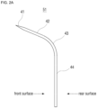
- FIG. 2A is a side view illustrating an embodiment of an integrated blade 51
- FIG. 2B is a side view illustrating an embodiment of a large steel blade.
- the integral blade 51 may include a base portion 44 seated on the support members 70a and 70b (see FIG. 3B ), a cutting portion 42 including a cutting edge 41 at a front end side, and a bent portion 43 that is bent forward and configured to connect the base portion 44 and the cutting portion 42.
- Such an integral blade 51 may be manufactured using a single body by a bending process and may be designed such that a span between integral blades 51 is relatively narrow and the integral blade 51 has a relatively small thickness.
- the large steel blade 52 is formed of two members including a metal support 40 seated on the support members 70a and 70b (see FIG. 3B ) and a cutting portion 45 that is bound to the metal support 40 on the metal support 40 and includes a cutting edge 46.
- the metal support 40 includes a base portion 49 and a bent portion 48 and includes a blade attaching portion 47 configured to support and secure the cutting portion 45.
- Such a metal support 40 of the large steel blade 52 may be formed to be thicker than the cutting portion 45 and may firmly support the cutting portion 45.
- the razor blade 5 may be configured with the above-described integral blade 51 or the large steel blade 52. However, embodiments are not limited thereto, and the razor blade 5 may be configured of any blade such as a straight blade or blades having various other forms as long as the blade has a shaving function.
- a pair of fixing clips 7a and 7b configured to fix both ends of the cutting edge of the razor blade 5 to the blade housing 60 may be included.
- FIGS. 1A to 1D illustrate an embodiment in which the fixing clips 7a and 7b are a rear wrap-around type such that the fixing clips 7a and 7b pass through a through-hole formed in the vicinity of a front end of the blade housing 60 and wrap around a rear end of the blade housing 60.
- the blade housing 60 may include, at the bottom surface 11, ribs 12a and 12b configured to support the blade housing 60 in a direction that is perpendicular to an alignment direction of the razor blade 5.
- the ribs 12a and 12b are structures that reinforce the blade housing 60 in a direction across the razor blade 5.
- the pair of ribs 12a and 12b may be disposed at left and right sides of the blade housing 60. However, embodiments are not limited thereto, and a greater number of ribs may also be disposed.
- the ribs 12a and 12b include guide surfaces 14a and 14b configured to guide a connector 20 to be easily engaged. At the bottom surface 11 of the blade housing 60, the guide surfaces 14a and 14b are progressively inclined toward the center of the ribs 12a and 12b, respectively.
- a first beam 18 is formed at a portion that is substantially between the razor blade 5 and the cap 3, and the first beam 18 includes a hook coupling portion 15 that is engaged with an elastic hook 23 (see FIG. 9A ) of the connector 20.
- a second beam 19 is formed at a portion that is substantially between the guard bar 1 and the razor blade 5, and the second beam 19 includes a central bar 17 that is pushed upon contact with a plunger (not illustrated) of a razor handle 30 when the plunger (not illustrated) protrudes. When the central bar 17 is pushed due to the plunger, the central bar 17 may be elastically deformed, to some extent, in a direction opposite to the plunger.
- the blade housing 60 may include, in addition to the ribs 12a and 12b or in place of the ribs 12a and 12b, one or more support members 70a and 70b configured to connect and support the blade housing 60 in a direction (hereinafter the "transverse direction") that is perpendicular to the direction in which the razor blade 5 is disposed, (hereinafter the "longitudinal direction").
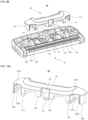
- FIGS. 3A and 3B are a perspective view and a plan view, respectively, of the blade housing 60 in a state in which the razor blade 5, a lubrication band 3, and the fixing clips 7a and 7b are removed from the razor cartridge 10.
- the guard bar 1 is illustrated as being integrally formed with the blade housing 60, but embodiments are not limited thereto.
- the guard bar 1 may be separately formed from the blade housing 60 and may be embedded in or assembled to the blade housing 60.
- the blade housing 60 may be understood as a portion excluding the guard bar 1 in FIG. 3 .
- the blade housing 60 may be basically understood as a quadrilateral frame structure including a front portion 61, a rear portion 62 formed opposite the front portion 61, and a left side portion 63 and a right side portion 64 configured to connect the front portion 61 and the rear portion 62.
- the blade housing 60 includes the one or more support members 70a and 70b configured to connect and support the blade housing 60 in the direction that is perpendicular to the direction in which the razor blade 5 is disposed.
- the support members 70a and 70b connect the front portion 61 and the rear portion 62 of the blade housing 60.
- FIG. 3B A case in which two support members 70a and 70b are used is illustrated in FIG. 3B , but embodiments are not limited thereto.
- the number of support members may be any number that is 1 or greater and that is suitable for seating the razor blade 5.
- a plurality of seating protrusions 71 and 72 for seating the at least one razor blade 5 are disposed along the support members 70a and 70b, e.g., aligned along the transverse direction.
- one or more ribs 12a and 12b configured to reinforce the blade housing 60 may be further included.
- the ribs 12a and 12b may be omitted or be integrally formed with the support members 70a and 70b.
- the plurality of seating protrusions 71 and 72 include a first seating protrusion 71 having a first height h1 (see FIG. 4C ) and a second seating protrusion 72 having a second height h2 (see FIG. 4C ) lower than the first height toward an upper portion of the blade housing 60 (in a direction that is upward in FIG. 3B and is opposite to the razor handle).
- the first seating protrusion 71 and the second seating protrusion 72 may be disposed to be parallel on the support members 70a and 70b.
- the first seating protrusion 71 and the second seating protrusion 72 may be alternately disposed on the support members 70a and 70b.
- a plurality of pressing protrusions 65a and 65b may be respectively formed at the right side portion 64 and the left side portion 63 of the blade housing 60.
- Such pressing protrusions 65a and 65b are also generally referred to as finger portions and press the razor blade 5 due to a stepped structure formed therein. By the pressing, the razor blade 5 is seated on the blade housing 60.
- the plurality of razor blades 5 are simultaneously inserted into seating slots formed due to gaps between the first seating protrusion 71 and the second seating protrusion 72 and inserted between the pressing protrusions 65a and 65b. Therefore, in the embodiment illustrated in FIG. 3B , a single razor blade 5 may be supported at a total of four positions.
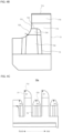
- FIGS. 4A to 4D are a perspective view, a rear view, a right side view, and a plan view, respectively, of the support member 70a disposed at the right of the two support members 70a and 70b.
- the first seating protrusion 71 and the second seating protrusion 72 are disposed to be parallel on the support member 70a.
- the first seating protrusion 71 and the second seating protrusion 72 are alternately disposed on the support member 70a.
- the first seating protrusion 71 includes a front surface 711, a rear surface 712, and an upper surface 713, and a first groove 715 is formed across the upper surface 713 and side surfaces.
- the first groove 715 is formed at a corner that faces the outside of the blade housing 60 among corners of the upper surface 713 of the first seating protrusion 71.
- an inclined surface 714 is formed from the upper surface 713 toward the rear surface 712 of the first seating protrusion 71.
- Such an inclined surface 714 is an element for supporting the razor blade 5 while coming into contact therewith in a shape similar to an inner surface of the bent portion 43 (see FIG. 6A ) of the razor blade 5.
- the inclined surface 714 may have a round shape having a predetermined curvature. Therefore, as illustrated in FIG. 6A which will be described below, the inclined surface 714 may support at least a portion of a front surface of an integral blade.
- At least one point of the blade attaching portion 47 or the bent portion 48 may be supported by the inclined surface 714 of the first seating protrusion 71 or supported by the upper surface 713 of the first seating protrusion 71.
- the second seating protrusion 72 includes a front surface 721, a rear surface 722, and an upper surface 723, and a second groove 725 is formed across the upper surface 723 and side surfaces.
- the second groove 725 is formed at a corner that faces the outside of the blade housing 60 among corners of the upper surface 723 of the second seating protrusion 72.
- the second seating protrusion 72 has a tapered surface 724 so as to be progressively tapered toward the upper surface.
- Such a tapered surface 724 is an element that allows the razor blade 5 to be inserted into a correct position even if there is a slight error in an insertion position when inserting the razor blade 5 between the first seating protrusion 71 and the second seating protrusion 72.
- a profile of the first groove 715 of the first seating protrusion 71 and a profile of the second groove 725 of the second seating protrusion 72 may match in the transverse direction.
- embodiments are not limited thereto, and the profile of the first groove 715 and the profile of the second groove 725 may also be different from each other. For example, they may have different sizes or shapes.
- the groove 715 may be formed in the first seating protrusion 71 while the groove 725 is not formed in the second seating protrusion 72. This is because, since the size of the second seating protrusion 72 is smaller than that of the first seating protrusion 71, a defect problem is less likely to occur in the second seating protrusion 72 during an injection molding process.
- the center of the first groove of the first seating protrusion 71 and the center of the second groove of the second seating protrusion 72 are aligned to be parallel along a virtual line La.
- the size of the first groove 715 is larger than the size of the second groove 725.
- FIG. 4B illustrating a rear view of the support member 70a of FIG. 4A
- the profiles of the second groove 725 of the second seating protrusion 72 and the first groove 715 of the first seating protrusion 71 match.
- the center of the second groove 725 and the center of the first groove 715 are also collinear with the virtual line La.
- the reason why the profile of the first groove 715 and the profile of the second groove 725 are formed to match each other is to facilitate withdrawal of a product during injection molding.
- the grooves 715 and 725 serve as undercuts for withdrawing a product after injection molding when manufacturing the support members 70a and 70b.
- the positions of the undercuts may match in the transverse direction.
- the height h2 of the second seating protrusion 72 may be lower than the height h1 of the first seating protrusion 71.
- a width w2 of the second seating protrusion 72 may be narrower than a width w1 of the first seating protrusion 71.
- the height h1 may be in a range of about 1.5 to 3 mm, and the height h2 may be in a range of about 50 to 70% of the height h1.
- the size of the width w1 may be substantially similar to that of the height h1, and the width w2 may be about 45 to 65% of the width w1.
- the size of the first seating protrusion 71 may be larger than that of the second seating protrusion 72 as a whole, and a sufficient clearance is secured during injection molding by the first seating protrusion 71, which is relatively larger, and the second seating protrusion 72, which is relatively smaller, being alternately disposed. In this way, an injection failure problem that occurs when manufacturing an injection-molded product having a very narrow and deep groove may be significantly improved.
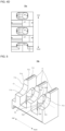
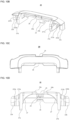
- FIG. 5 is a perspective view of an embodiment of the support member 70b disposed at the left of the two support members 70a and 70b.
- the first seating protrusion 71 and the second seating protrusion 72 are alternately disposed parallel to each other in the transverse direction.
- two first seating protrusions 71 and three second seating protrusions 72 are alternately disposed in the support member 70a of FIG. 4A
- three first seating protrusions 71 and two second seating protrusions 72 are alternately disposed in the support member 70b of FIG. 5 . Therefore, at corresponding positions, different types of seating protrusions 71 and 72 are disposed on the support members 70a and 70b.
- first seating protrusion 71 and the second seating protrusion 72 are alternately disposed in a first order on the left support member 70b while the first seating protrusion 71 and the second seating protrusion 72 are alternately disposed in a second order on the right support member 70a.
- the first order and the second order are reverse orders. Such arrangements are performed in order to allow a front surface (or a rear surface) of the razor blade 5 to be supported by the first seating protrusion 71 in at least one point of the two support members 70a and 70b.
- FIG. 6A is a cross-sectional view of the razor cartridge 10 of FIG. 1B taken along line A-A' in FIG. 1B . Since a folding position in the blade housing 170 is difficult to clearly distinguish in FIG. 1B due to the seated razor blade 5, the line A-A' is also marked for reference in the blade housing 60 of FIG. 3B .
- first seating protrusions 71 and second seating protrusions 72 which are alternately disposed in the left support member 70b.
- first seating protrusions 71 indicated with slashes are those formed in the left support member 70b
- first seating protrusions 71 without slashes are those formed in the right support member 70a.
- the second seating protrusions formed on the right support member 70A are not illustrated since the second seating protrusions are obscured by the first seating protrusions 71 indicated with slashes.
- each of the razor blades 5a to 5e is supported by a first seating protrusion 71.
- each of the razor blades 5a to 5e is illustrated as the integral blade 51 which is illustrated in FIG. 2A .
- each of the razor blades 5a to 5e include the cutting portion 42, the bent portion 43, and the base portion 44
- portions of the cutting portion 42 and the bent portion 43 at the front surfaces of the razor blades 5a to 5e may be supported by the upper surface 713 or the inclined surface 714 of the first seating protrusion 71.
- the base portion 44 may be inserted into the gap (seating slot) between the first seating protrusion 71 and the second seating protrusion 72 and be supported between the first seating protrusion 71 and the second seating protrusion 72.
- various points of the razor blade excluding the cutting edges of the razor blades 5a to 5e may be supported by the first seating protrusion 71 and the second seating protrusion 72.
- each of the razor blades 5a to 5e of FIG. 6A may also be implemented as the large steel blade 52 instead of the integral blade 51.
- FIG. 6B shows an embodiment in which large steel blades 52 are seated on the support members 70a and 70b of the blade housing 60.
- each of the razor blades 5a to 5e may be formed of two members including the cutting portion 45 and the metal support 40.
- the cutting portion 45 has a cutting edge 46 formed at a front end
- the metal support 40 includes a base portion 49 to be inserted into a seating slot, a blade attaching portion 47 to which the cutting portion 45 is bound, and a bent portion 48 configured to connect the base portion 49 and the blade attaching portion 47.
- portions of the blade attaching portion 47 and the bent portion 48 in the front surfaces of the razor blades 5a to 5e may be supported by the upper surface 713 or the inclined surface 714 of the first seating protrusion 71.
- the base portion 49 may be inserted into the gap (seating slot) between the first seating protrusion 71 and the second seating protrusion 72 and be supported between the first seating protrusion 71 and the second seating protrusion 72.
- various points of the metal support 40 excluding the cutting portion 45 may be supported by the first seating protrusion 71 and the second seating protrusion 72.
- various points of the razor blades 5a to 5e excluding the cutting edges may be fixed or supported by the first seating protrusion 71 or the second seating protrusion 43.
- surface-to-surface contact and support may not necessarily occure between the razor blades 5a to 5e and the first and second seating protrusions 71 and 72.
- portions of front surfaces of the blades 5a to 5e may be supported by the upper surface 713 or the inclined surface 714 of the first seating protrusion 71, lower ends of rear surfaces of the razor blades 5a to 5e may be supported upon contact with the second seating protrusion 72 in the vicinity of a lower end of a front surface of the second seating protrusion 72.
- the front surfaces of the razor blades 5a to 5e may be supported by the first seating protrusion 71 at a higher point, and the rear surfaces of the razor blades 5a to 5e may be supported by the second seating protrusion 72 at a lower point.
- the razor blades 5a to 5e are integral blades 51 or large steel blades 52, since at least a portion of the front surfaces of the razor blades 5a to 5e excluding the cutting edges are firmly supported by the first seating protrusion 71 and the second seating protrusion 72, a problem of shaking or deformation of the blades 5a to 5e during shaving may be prevented.
- portions of the front surfaces and portions of the rear surfaces of the razor blades 5a to 5e may be respectively supported by the first seating protrusion 71 and the second seating protrusion 72, or conversely, may be respectively supported by the second seating protrusion 72 and the first seating protrusion 71.
- a portion of a front surface thereof is supported by the rear surface 722 of the second seating protrusion 72 and a portion of a rear surface thereof is supported by the front surface 711 of the first seating protrusion 71 on the first support member 70a.
- a portion of the front surface of the third razor blade 5c is supported by the rear surface 712, the upper surface 713, or the inclined surface 714 of the first seating protrusion 71 and a portion of the rear surface thereof is supported by the front surface 721 of the second seating protrusion 72.
- the alternating support patterns of the seating protrusions 71 and 72 with respect to the specific razor blade 5c may apply similarly to the other razor blades 5a, 5b, 5d, and 5e.
- the front surfaces of specific razor blades 5a to 5e may be firmly supported by the first seating protrusion 71 on at least one support member.
- FIG. 7 is a transverse cross-sectional view of the razor cartridge 10 of FIG. 1C taken along line B-B' in FIG. 1C .
- the razor blades 5a to 5e may be stably supported between the first and second seating protrusions 71 and 72.
- a rear surface of the last blade 5e may be caused to be directly supported by a rear wall 66 of the blade housing 60 instead of the seating protrusions 71 and 72.
- the structure of the blade housing 60 may be further simplified.
- protrusions 67a and 67b may be disposed at positions at which the support members 70a and 70b meet the rear wall 66, but embodiments are not limited thereto.
- the arrangement positions and the numbers of the protrusions 67a and 67b may be selected from various choices as necessary.
- each of the razor blades 5a to 5e may be supported at a total of four positions along the longitudinal direction.
- a single support member may be disposed at the center of the blade housing 60 in the transverse direction, or three or more support members may be disposed in the blade housing 60, and in some cases more than one seating protrusion may be disposed on the single support member in the longitudinal direction.
- the pressing protrusions 65a and 65b formed at the right side portion 64 and the left side portion 63 of the blade housing 60 are illustrated as having forms different from those of the seating protrusions 71 and 72 disposed in the support members 70a and 70b, but embodiments are not limited thereto.
- the pressing protrusions 65a and 65b may also be replaced with the seating protrusions 71 and 72. In this case, all of the support members 70a and 70b and the right side portion 64 and the left side portion 63 support the razor blades 5a to 5e by the seating protrusions 71 and 72.
- the number of razor blades may also be selected from various choices.
- the number of first seating protrusions 71 and second seating protrusions 72 may also be increased or decreased corresponding to the selected number of razor blades.
- a razor cartridge assembly 50 including the razor cartridge 10 and a connector 20 configured to detachably assemble the razor cartridge 10 to the razor handle 30 will be described in detail.
- FIG. 8A is a perspective view of a razor 100 according to an embodiment of the present disclosure from a rear surface of the razor handle 30 (from a side at which a bottom surface of the razor cartridge 10 is visible), and FIG. 8B is a perspective view in which the razor cartridge assembly 50 is separated from the razor handle 30 of FIG. 8A .
- the razor 100 includes the razor cartridge assembly 50 including the razor cartridge 10 and the connector 20, which is fixed and coupled to the razor cartridge 10, and the razor handle 30, which is detachably coupled to the razor cartridge assembly 50.
- a pair of plunger guards 31 are formed at an end of the razor handle 30, and the plunger guards 31 may be inserted into or detached from a coupling space included in the razor cartridge assembly 50.
- a slider button 37 disposed on a rear surface of the razor handle 30 is pushed toward the razor cartridge assembly 50.
- a plunger (not illustrated) which is under elastic bias between the pair of plunger guards 31 protrudes toward one side of the razor cartridge assembly 50 and pushes the one side, and accordingly, the plunger guards 31 are detached from the razor cartridge assembly 50.
- the plunger guards 31 may pivot within a predetermined angle range about a rotation axis ax formed in the vicinity of an end of the razor handle 30. Accordingly, when the plunger guards 31 are coupled to the razor cartridge assembly 50, the razor cartridge assembly 50 may also pivot about the rotation axis "ax.”
- FIGS. 9A and 9B are perspective views in different directions that show the positional relationship between a bottom surface of the razor cartridge 10 and the connector 20 before the two are coupled.
- a combination of inner cantilevers 21a and 21b and outer cantilevers 22a and 22b facing the inner cantilevers 21a and 21b (hereinafter referred to as inner-outer cantilevers) hold the ribs 12a and 12b from both sides.
- an elastic hook 23 is formed between the two pairs of inner-outer cantilevers in the connector 20 and is coupled to a hook coupling portion 15 formed between the pair of ribs 12a and 12b at the bottom surface of the razor cartridge 10.
- FIGS. 10A to 10D are views for describing a structure of the connector 20 according to an embodiment of the present disclosure in more detail.
- FIGS. 10A and 10B are perspective views of the connector 20 seen in different directions
- FIGS. 10C and 10D are a plan view and a bottom view, respectively, of the connector 20.
- the connector 20 may further include the elastic hook 23 that is able to be coupled to the hook coupling portion 15 of the razor cartridge 10 at a position corresponding to the hook coupling portion 15.
- the connector 20 may include a pair of step portions 24a and 24b that are formed near the elastic hook 23 and are configured to guide the hook coupling portion 15 so that the elastic hook 23 and the hook coupling portion 15 are coupled to each other at correct positions.
- the stepped portions 24a and 24b may have vertically symmetrical shapes with respect to the elastic hook 23, and a guide slot 25, which is a space in which the hook coupling portion 15 may move while being guided, is formed between the two stepped portions 24a and 24b.
- a clearance groove 26, which is disposed at a predetermined interval y from the central bar 17 of the razor cartridge 10 during assembly of the razor cartridge 10 and the connector 20, is formed.
- the central bar 17 is pushed while being elastically deformed to some extent in a direction opposite from the plunger.
- the clearance groove 26 provides a space in which the pushed central bar 17 may be bent while having slight elasticity.
- a recess portion 27 which is substantially arc shape is formed in an inner surface of the connector 20.
- the recess portion 27 has a profile that matches an outer shape of the pair of plunger guards 31 (see FIGS. 12A to 12C ) formed at a proximal end of the razor handle 30.
- FIG. 11 is a bottom view of an assembly of the connector 20 and the razor cartridge 10, that is, the razor cartridge assembly 50.
- an engagement space 55 into which the proximal end of the razor handle 30 may be inserted toward the front end of the razor cartridge 10 is formed between the razor cartridge 10 and the connector 20.
- the inner cantilevers 21a and 21b form both ends of the engagement space 55 in a transverse direction d.
- the engagement space 55 is divided into two areas by the central bar 17 of the razor cartridge 10, and the pair of plunger guards 31 may be respectively inserted into the two areas.
- the plunger (not illustrated) of the razor handle 30 protrudes due to a user's manipulation. Therefore, the plunger pushes the central bar 17, and the pair of plunger guards 31 retreat from the engagement space 55 and are separated therefrom. In this case, the central bar 17 that is pushed by the plunger may be bent within a predetermined interval y range while having slight elasticity.
- FIG. 12A is an exploded perspective view of the razor 100 according to an embodiment of the present disclosure
- FIG. 12B is a side view of the exploded perspective view of FIG. 12A
- 12C is a plan view of the exploded perspective view of FIG. 12A .
- the pair of plunger guards 31 may be detachably coupled to the engagement space 55 formed in the razor cartridge assembly 50.
- the engagement space 55 may be divided into two areas by the central bar 17, and the pair of plunger guards 31 may be respectively inserted into the two areas. That is, when the pair of plunger guards 31 are inserted into the engagement space 55, the central bar 17 supports a space between the pair of plunger guards 31.
- the plunger guards 31 may be disposed at a proximal end side of a cartridge mounter 35 that is separately disposed to be able to be coupled to a handle grip 39, and the plunger guards 31 may pivot within a predetermined angle range about the rotation axis ax that is parallel with the transverse direction d of the razor. Therefore, while shaving is performed, the razor cartridge assembly 50 which is coupled to the plunger guards 31 may also pivot about the rotation axis ax according to a user's manipulation.
- a coupling member 33 is formed at a distal end side of the cartridge mounter 35 so that the cartridge mounter 35 may be coupled to a proximal end side of the handle grip 39.
- the cartridge mounter 35 may also be integrally formed with the handle grip 39 instead of being manufactured as a separate element and coupled to the handle grip 39.
- the slider button 37 is formed at one side of the cartridge mounter 35.
- the user may cause the plunger (not illustrated) to protrude by pushing the slider button 37 upward toward the razor cartridge assembly 50.
- the pair of plunger guards 31 are disposed at the proximal end of the cartridge mounter 35, and a plunger is formed to be inserted or withdrawn between the pair of plunger guards 31.
- the plunger is at a position at which it does not protrude to the outside when there is no external force, and then when the user pushes the slider button 37 upward toward the razor cartridge assembly 50, the plunger protrudes toward the razor cartridge assembly 50 from between the two plunger guards 31. Due to the plunger, which protrudes as above, pushing the central bar 17 (see FIG. 9B ), the plunger guards 31, which have been coupled to the engagement space 55, are detached from the razor cartridge assembly 50.
- seating protrusions are disposed in a row to stably support blades on a blade housing while the seating protrusions are disposed at different heights. In this way, there is an advantage in that, while injection of the blade housing including the seating protrusions is facilitated, the blades are stably supported on the blade housing.
- the order of arrangement of seating protrusions of a first support member and the order of arrangement of seating protrusions of a second support member are set to be different. In this way, there is an advantage in that, on at least one side, a plurality of blades can be supported by seating protrusions having a high height.
- inner and outer cantilevers expand and deform at both sides of a rib, which is formed at a bottom surface of a blade housing, and hold the rib, there is an advantage in that assembling can be firmly and conveniently performed.
Description
- The present disclosure relates to a razor cartridge, and more particularly, to a razor cartridge and razor cartridge assembly having seating protrusions for more firmly seating a plurality of razor blades on a blade housing.
- Generally, a conventional razor, which is known as a wet razor, includes a razor cartridge and a razor handle. Generally, the razor cartridge includes at least one blade disposed between a rear side of a guard bar and a front side of a cap and includes a blade housing for seating the blade. The razor cartridge is installed to be detachable from and pivotable on the razor handle so that the razor cartridge is able to pivot with respect to the razor handle, between a neutral position and a pivot position during use of the razor. Generally, such pivoting motion is basically performed about a rotation axis that is parallel to a direction in which the razor blade is disposed on the blade housing. In this way, since the razor cartridge is detachably disposed on the razor handle, the user may remove a razor cartridge whose razor blade has become dull to some extent and mount a new razor cartridge on the razor handle for use when shaving afterwards.
- However, in recent years, the number of blades mounted on a blade housing has been increasing, and in order to mount a plurality of blades on a narrow blade housing, a span between blades also has to be reduced corresponding to the narrow blade housing. In addition, accordingly, the size of seating portions for seating the plurality of blades on the blade housing also has to be reduced. Razor cartridges including a plurality of blades are disclosed, for example, in
WO 2007/147420 A1 ,EP 0 064 190 A2 ,US 2011/0308089 A1 andWO 99/165592 A1 - To address the reduction in blade housing size, a razor having a corrugated protrusion has been proposed. According to this razor, sludge discharge is possible between blades, and the blades may be stably fixed. However, in a case in which, due to a narrow span between blades, protrusions corresponding thereto have to be formed at narrow intervals, it may be difficult to form the protrusions by injection molding, and even if injection molding is possible, high accuracy is required in a subsequent assembling process due to the narrow intervals between the protrusions. In addition, it may be difficult for the protrusions formed by injection molding to firmly support the plurality of blades.
- Therefore, there is a need to devise a blade seating portion, which has a structure capable of stably storing and keeping razor blades which have a narrow span therebetween or have a relatively thin base portion, and a razor cartridge including the same.
- Aspects of the present disclosure provide a razor cartridge having seating protrusions for stably supporting blades on a blade housing.
- Aspects of the present disclosure also provide a razor cartridge having a structure in which injection of a support member for supporting blades on a blade housing and a seating protrusion formed on the support member is facilitated.
- Aspects of the present disclosure also provide a razor cartridge assembly including a connector that is able to be promptly and easily assembled to a blade housing.
- It should be noted that objects of the present disclosure are not limited to the above-described objects, and other objects of the present disclosure will be apparent to those skilled in the art from the following descriptions.
- To achieve the above objects, the present invention provides a razor cartridge as defined in the claims.
- The above and other aspects and features of the present disclosure will become more apparent by describing exemplary embodiments thereof in detail with reference to the attached drawings, in which:
-
FIGS. 1A to 1D are a perspective view, a plan view, a front view, and a bottom view, respectively, of a razor cartridge according to an embodiment of the present disclosure; -
FIGS. 2A and2B are side views of an integrated blade and a large steel blade, respectively, according to an embodiment of the present disclosure; -
FIGS. 3A and 3B are a perspective view and a plan view, respectively, of a blade housing in a state in which razor blades, a lubrication band, and a fixing clip are removed from a razor cartridge; -
FIGS. 4A ,4B ,4C , and4D are a perspective view, a rear view, a right side view, and a plan view, respectively, of a support member disposed at the right of two support members; -
FIG. 5 is a perspective view of a support member disposed at the left of the two support members; -
FIG. 6A is a cross-sectional view of the razor cartridge ofFIG. 1B taken along line A-A' inFIG. 1B ; -
FIG. 6B is a cross-sectional view of the razor cartridge ofFIG. 6A in which integrated blades are replaced with large steel blades; -
FIG. 7 is a transverse cross-sectional view of the razor cartridge ofFIG. 1C taken along line B-B' inFIG. 1C ; -
FIG. 8A is a perspective view of a razor according to an embodiment of the present disclosure from a rear surface of a razor handle, andFIG. 8B is a perspective view in which a razor cartridge assembly is separated from the razor handle ofFIG. 8A ; -
FIGS. 9A and9B are perspective views in different directions that show the positional relationship between a bottom surface of a razor cartridge and a connector before the two are coupled; -
FIGS. 10A ,10B, 10C, and 10D are views for describing a structure of the connector according to an embodiment of the present disclosure in more detail; -
FIG. 11 is a bottom view of a razor cartridge assembly according to an embodiment of the present disclosure; and -
FIG. 12A is an exploded perspective view of a razor according to an embodiment of the present disclosure,FIG. 12B is a side view of the exploded perspective view ofFIG. 12A , and12C is a plan view of the exploded perspective view ofFIG. 12A . - Advantages and features of the present disclosure and a method of achieving the same should become clear with embodiments described in detail below with reference to the accompanying drawings. However, the present disclosure is not limited to embodiments disclosed below and may be realized in various other forms. The present embodiments make the disclosure complete and are provided to completely inform one of ordinary skill in the art to which the present disclosure pertains of the scope of the disclosure. The present disclosure is defined only by the scope of the claims. Like reference numerals refer to like elements throughout.
- Unless otherwise defined, all terms including technical and scientific terms used herein have the same meaning as commonly understood by one of ordinary skill in the art to which the present disclosure pertains. Terms, such as those defined in commonly used dictionaries, are not to be construed in an idealized or overly formal sense unless expressly so defined herein.
- Terms used herein are for describing the embodiments and are not intended to limit the present disclosure. In the present specification, a singular expression includes a plural expression unless the context clearly indicates otherwise. "Comprises" and/or "comprising" used herein do not preclude the existence or the possibility of adding one or more elements other than those mentioned.
- Hereinafter, an embodiment of the present disclosure will be described in detail with reference to the accompanying drawings.
-
FIG. 1A is a perspective view of arazor cartridge 10 according to an embodiment of the present disclosure,FIG. 1B is a plan view of therazor cartridge 10,FIG. 1C is a front view of therazor cartridge 10, andFIG. 1D is a bottom view of therazor cartridge 10. Therazor cartridge 10 may include at least onerazor blade 5 having a cutting edge, ablade housing 60 configured to accommodate the at least onerazor blade 5, aguard bar 1 disposed at afront portion 61 of theblade housing 60, and acap 3 disposed at arear portion 62 of the blade housing. Theguard bar 1 causes facial hair of a user to stand upright in a direction that is substantially perpendicular to a shaving direction so that cutting facial hair by therazor blade 5 is facilitated. Theguard bar 1 may be manufactured as a firm member or a flexible member. Thecap 3 may include a lubrication band as a contact surface that is detached from the skin last during a shaving stroke. The lubrication band serves to soothe irritated skin after the cutting. - The
razor blade 5 has a cutting edge at one end, and the other end of therazor blade 5 may be seated onsupport members FIG. 3B ) included in theblade housing 60. In this case, asingle razor blade 5 or two ormore razor blades 5 may be disposed, and a direction in which therazor blade 5 is accommodated in theblade housing 60 is a longitudinal direction that is perpendicular to a general shaving direction. Such arazor blade 5 may be formed of stainless steel, ceramic, and/or various other metal materials and may be formed as an integral blade that is integrally formed through a bending process or a large steel blade that is formed by attaching a blade edge portion to an upper portion of a bent support. -
FIG. 2A is a side view illustrating an embodiment of anintegrated blade 51, andFIG. 2B is a side view illustrating an embodiment of a large steel blade. Referring toFIG. 2A , theintegral blade 51 may include abase portion 44 seated on thesupport members FIG. 3B ), a cuttingportion 42 including acutting edge 41 at a front end side, and abent portion 43 that is bent forward and configured to connect thebase portion 44 and the cuttingportion 42. Such anintegral blade 51 may be manufactured using a single body by a bending process and may be designed such that a span betweenintegral blades 51 is relatively narrow and theintegral blade 51 has a relatively small thickness. - In another embodiment, as illustrated in
FIG. 2B , thelarge steel blade 52 is formed of two members including ametal support 40 seated on thesupport members FIG. 3B ) and a cuttingportion 45 that is bound to themetal support 40 on themetal support 40 and includes acutting edge 46. Like theintegral blade 51, themetal support 40 includes abase portion 49 and abent portion 48 and includes ablade attaching portion 47 configured to support and secure the cuttingportion 45. Such ametal support 40 of thelarge steel blade 52 may be formed to be thicker than the cuttingportion 45 and may firmly support the cuttingportion 45. - Generally, the
razor blade 5 may be configured with the above-describedintegral blade 51 or thelarge steel blade 52. However, embodiments are not limited thereto, and therazor blade 5 may be configured of any blade such as a straight blade or blades having various other forms as long as the blade has a shaving function. - Meanwhile, in order to prevent detachment of the
razor blade 5 from theblade housing 60, a pair of fixingclips razor blade 5 to theblade housing 60 may be included. The pair of fixingclips razor blade 5, pass through at least one through-hole formed in the vicinity of both ends of theblade housing 60 and may be bent at abottom surface 11 of theblade housing 60.FIGS. 1A to 1D illustrate an embodiment in which the fixingclips clips blade housing 60 and wrap around a rear end of theblade housing 60. - Referring to the bottom view of the
razor cartridge 10 illustrated inFIG. 1D , theblade housing 60 may include, at thebottom surface 11,ribs blade housing 60 in a direction that is perpendicular to an alignment direction of therazor blade 5. Theribs blade housing 60 in a direction across therazor blade 5. The pair ofribs blade housing 60. However, embodiments are not limited thereto, and a greater number of ribs may also be disposed. Theribs guide surfaces connector 20 to be easily engaged. At thebottom surface 11 of theblade housing 60, the guide surfaces 14a and 14b are progressively inclined toward the center of theribs - In addition, at the
bottom surface 11 of theblade housing 60, afirst beam 18 is formed at a portion that is substantially between therazor blade 5 and thecap 3, and thefirst beam 18 includes ahook coupling portion 15 that is engaged with an elastic hook 23 (seeFIG. 9A ) of theconnector 20. In addition, at thebottom surface 11 of theblade housing 60, asecond beam 19 is formed at a portion that is substantially between theguard bar 1 and therazor blade 5, and thesecond beam 19 includes acentral bar 17 that is pushed upon contact with a plunger (not illustrated) of arazor handle 30 when the plunger (not illustrated) protrudes. When thecentral bar 17 is pushed due to the plunger, thecentral bar 17 may be elastically deformed, to some extent, in a direction opposite to the plunger. - Meanwhile, the
blade housing 60 may include, in addition to theribs ribs more support members blade housing 60 in a direction (hereinafter the "transverse direction") that is perpendicular to the direction in which therazor blade 5 is disposed, (hereinafter the "longitudinal direction"). -
FIGS. 3A and 3B are a perspective view and a plan view, respectively, of theblade housing 60 in a state in which therazor blade 5, alubrication band 3, and the fixingclips razor cartridge 10. Here, theguard bar 1 is illustrated as being integrally formed with theblade housing 60, but embodiments are not limited thereto. Theguard bar 1 may be separately formed from theblade housing 60 and may be embedded in or assembled to theblade housing 60. In the case in which theguard bar 1 is separately formed as described above, theblade housing 60 may be understood as a portion excluding theguard bar 1 inFIG. 3 . - As illustrated in
FIGS. 3A and 3B , theblade housing 60 may be basically understood as a quadrilateral frame structure including afront portion 61, arear portion 62 formed opposite thefront portion 61, and aleft side portion 63 and aright side portion 64 configured to connect thefront portion 61 and therear portion 62. In addition, theblade housing 60 includes the one ormore support members blade housing 60 in the direction that is perpendicular to the direction in which therazor blade 5 is disposed. In one embodiment, thesupport members front portion 61 and therear portion 62 of theblade housing 60. - A case in which two
support members FIG. 3B , but embodiments are not limited thereto. The number of support members may be any number that is 1 or greater and that is suitable for seating therazor blade 5. - A plurality of
seating protrusions razor blade 5 are disposed along thesupport members support members more ribs blade housing 60 may be further included. However, embodiments are not limited thereto, and theribs support members - The plurality of
seating protrusions first seating protrusion 71 having a first height h1 (seeFIG. 4C ) and asecond seating protrusion 72 having a second height h2 (seeFIG. 4C ) lower than the first height toward an upper portion of the blade housing 60 (in a direction that is upward inFIG. 3B and is opposite to the razor handle). In this case, thefirst seating protrusion 71 and thesecond seating protrusion 72 may be disposed to be parallel on thesupport members first seating protrusion 71 and thesecond seating protrusion 72 may be alternately disposed on thesupport members - In addition, a plurality of pressing
protrusions right side portion 64 and theleft side portion 63 of theblade housing 60. Suchpressing protrusions razor blade 5 due to a stepped structure formed therein. By the pressing, therazor blade 5 is seated on theblade housing 60. - The plurality of
razor blades 5 are simultaneously inserted into seating slots formed due to gaps between thefirst seating protrusion 71 and thesecond seating protrusion 72 and inserted between thepressing protrusions FIG. 3B , asingle razor blade 5 may be supported at a total of four positions. -
FIGS. 4A to 4D are a perspective view, a rear view, a right side view, and a plan view, respectively, of thesupport member 70a disposed at the right of the twosupport members FIGS. 4A to 4C , thefirst seating protrusion 71 and thesecond seating protrusion 72 are disposed to be parallel on thesupport member 70a. Particularly, thefirst seating protrusion 71 and thesecond seating protrusion 72 are alternately disposed on thesupport member 70a. - In some embodiments, the
first seating protrusion 71 includes afront surface 711, arear surface 712, and anupper surface 713, and afirst groove 715 is formed across theupper surface 713 and side surfaces. In this case, thefirst groove 715 is formed at a corner that faces the outside of theblade housing 60 among corners of theupper surface 713 of thefirst seating protrusion 71. In addition, aninclined surface 714 is formed from theupper surface 713 toward therear surface 712 of thefirst seating protrusion 71. - Such an
inclined surface 714 is an element for supporting therazor blade 5 while coming into contact therewith in a shape similar to an inner surface of the bent portion 43 (seeFIG. 6A ) of therazor blade 5. For example, theinclined surface 714 may have a round shape having a predetermined curvature. Therefore, as illustrated inFIG. 6A which will be described below, theinclined surface 714 may support at least a portion of a front surface of an integral blade. For example, in the front surface of theintegral blade 51 illustrated inFIG. 2A , at least one point of the cuttingportion 42 or thebent portion 43 may be supported by theinclined surface 714 of thefirst seating protrusion 71 or supported by theupper surface 713 of thefirst seating protrusion 71. - Likewise, in the front surface of the
large steel blade 52 illustrated inFIG. 2B , at least one point of theblade attaching portion 47 or thebent portion 48 may be supported by theinclined surface 714 of thefirst seating protrusion 71 or supported by theupper surface 713 of thefirst seating protrusion 71. - In some embodiments, the
second seating protrusion 72 includes afront surface 721, arear surface 722, and anupper surface 723, and asecond groove 725 is formed across theupper surface 723 and side surfaces. In this case, thesecond groove 725 is formed at a corner that faces the outside of theblade housing 60 among corners of theupper surface 723 of thesecond seating protrusion 72. In addition, thesecond seating protrusion 72 has a taperedsurface 724 so as to be progressively tapered toward the upper surface. Such atapered surface 724 is an element that allows therazor blade 5 to be inserted into a correct position even if there is a slight error in an insertion position when inserting therazor blade 5 between thefirst seating protrusion 71 and thesecond seating protrusion 72. - A profile of the
first groove 715 of thefirst seating protrusion 71 and a profile of thesecond groove 725 of thesecond seating protrusion 72 may match in the transverse direction. However, embodiments are not limited thereto, and the profile of thefirst groove 715 and the profile of thesecond groove 725 may also be different from each other. For example, they may have different sizes or shapes. - Furthermore, the
groove 715 may be formed in thefirst seating protrusion 71 while thegroove 725 is not formed in thesecond seating protrusion 72. This is because, since the size of thesecond seating protrusion 72 is smaller than that of thefirst seating protrusion 71, a defect problem is less likely to occur in thesecond seating protrusion 72 during an injection molding process. - According to an embodiment, as illustrated in
FIG. 4A , the center of the first groove of thefirst seating protrusion 71 and the center of the second groove of thesecond seating protrusion 72 are aligned to be parallel along a virtual line La. In this case, the size of thefirst groove 715 is larger than the size of thesecond groove 725. - Referring to
FIG. 4B illustrating a rear view of thesupport member 70a ofFIG. 4A , it can be seen that the profiles of thesecond groove 725 of thesecond seating protrusion 72 and thefirst groove 715 of thefirst seating protrusion 71 match. In this case, the center of thesecond groove 725 and the center of thefirst groove 715 are also collinear with the virtual line La. The reason why the profile of thefirst groove 715 and the profile of thesecond groove 725 are formed to match each other is to facilitate withdrawal of a product during injection molding. Thegrooves support members - Referring to
FIGS. 4C and4D respectively illustrating the right side view and the plan view of thesupport member 70a ofFIG. 4A , the height h2 of thesecond seating protrusion 72 may be lower than the height h1 of thefirst seating protrusion 71. In addition, a width w2 of thesecond seating protrusion 72 may be narrower than a width w1 of thefirst seating protrusion 71. In some embodiments, the height h1 may be in a range of about 1.5 to 3 mm, and the height h2 may be in a range of about 50 to 70% of the height h1. In addition, the size of the width w1 may be substantially similar to that of the height h1, and the width w2 may be about 45 to 65% of the width w1. As a result, the size of thefirst seating protrusion 71 may be larger than that of thesecond seating protrusion 72 as a whole, and a sufficient clearance is secured during injection molding by thefirst seating protrusion 71, which is relatively larger, and thesecond seating protrusion 72, which is relatively smaller, being alternately disposed. In this way, an injection failure problem that occurs when manufacturing an injection-molded product having a very narrow and deep groove may be significantly improved. -
FIG. 5 is a perspective view of an embodiment of thesupport member 70b disposed at the left of the twosupport members right support member 70a, in theleft support member 70b, thefirst seating protrusion 71 and thesecond seating protrusion 72 are alternately disposed parallel to each other in the transverse direction. However, while twofirst seating protrusions 71 and threesecond seating protrusions 72 are alternately disposed in thesupport member 70a ofFIG. 4A , threefirst seating protrusions 71 and twosecond seating protrusions 72 are alternately disposed in thesupport member 70b ofFIG. 5 . Therefore, at corresponding positions, different types ofseating protrusions support members first seating protrusion 71 and thesecond seating protrusion 72 are alternately disposed in a first order on theleft support member 70b while thefirst seating protrusion 71 and thesecond seating protrusion 72 are alternately disposed in a second order on theright support member 70a. The first order and the second order are reverse orders. Such arrangements are performed in order to allow a front surface (or a rear surface) of therazor blade 5 to be supported by thefirst seating protrusion 71 in at least one point of the twosupport members -
FIG. 6A is a cross-sectional view of therazor cartridge 10 ofFIG. 1B taken along line A-A' inFIG. 1B . Since a folding position in the blade housing 170 is difficult to clearly distinguish inFIG. 1B due to the seatedrazor blade 5, the line A-A' is also marked for reference in theblade housing 60 ofFIG. 3B . - Referring to
FIG. 6A , fiverazor blades 5a to 5e are inserted into gaps (seating slots) betweenfirst seating protrusions 71 andsecond seating protrusions 72 which are alternately disposed in theleft support member 70b. Here, among the illustratedfirst seating protrusions 71, thefirst seating protrusions 71 indicated with slashes are those formed in theleft support member 70b, and thefirst seating protrusions 71 without slashes are those formed in theright support member 70a. The second seating protrusions formed on the right support member 70A are not illustrated since the second seating protrusions are obscured by thefirst seating protrusions 71 indicated with slashes. - As illustrated in
FIG. 6A , it can be seen that at least a portion of a front surface of each of the fiverazor blades 5a to 5e is supported by afirst seating protrusion 71. Here, each of therazor blades 5a to 5e is illustrated as theintegral blade 51 which is illustrated inFIG. 2A . - Specifically, when each of the
razor blades 5a to 5e include the cuttingportion 42, thebent portion 43, and thebase portion 44, portions of the cuttingportion 42 and thebent portion 43 at the front surfaces of therazor blades 5a to 5e may be supported by theupper surface 713 or theinclined surface 714 of thefirst seating protrusion 71. In addition, thebase portion 44 may be inserted into the gap (seating slot) between thefirst seating protrusion 71 and thesecond seating protrusion 72 and be supported between thefirst seating protrusion 71 and thesecond seating protrusion 72. According to various embodiments in which therazor blades 5a to 5e are seated on thesupport members razor blades 5a to 5e may be supported by thefirst seating protrusion 71 and thesecond seating protrusion 72. - Meanwhile, each of the
razor blades 5a to 5e ofFIG. 6A may also be implemented as thelarge steel blade 52 instead of theintegral blade 51.FIG. 6B shows an embodiment in whichlarge steel blades 52 are seated on thesupport members blade housing 60. - In this case, each of the
razor blades 5a to 5e may be formed of two members including the cuttingportion 45 and themetal support 40. The cuttingportion 45 has acutting edge 46 formed at a front end, and themetal support 40 includes abase portion 49 to be inserted into a seating slot, ablade attaching portion 47 to which the cuttingportion 45 is bound, and abent portion 48 configured to connect thebase portion 49 and theblade attaching portion 47. - When the
razor blades 5a to 5e are seated on thesupport members blade attaching portion 47 and thebent portion 48 in the front surfaces of therazor blades 5a to 5e may be supported by theupper surface 713 or theinclined surface 714 of thefirst seating protrusion 71. In addition, thebase portion 49 may be inserted into the gap (seating slot) between thefirst seating protrusion 71 and thesecond seating protrusion 72 and be supported between thefirst seating protrusion 71 and thesecond seating protrusion 72. Therefore, according to various embodiments in which therazor blades 5a to 5e are seated on thesupport members metal support 40 excluding the cuttingportion 45 may be supported by thefirst seating protrusion 71 and thesecond seating protrusion 72. - As described with reference to
FIGS. 6A and 6B , various points of therazor blades 5a to 5e excluding the cutting edges may be fixed or supported by thefirst seating protrusion 71 or thesecond seating protrusion 43. However, in some cases when seating therazor blades 5a to 5e on thesupport members razor blades 5a to 5e and the first andsecond seating protrusions blades 5a to 5e (for example, portions of the cuttingportion 42, thebent portion 43, and thebase portion 44 in the case of theintegral blade 51, and portions of theblade attaching portion 47, thebent portion 48, and thebase portion 49 in the case of the large steel blade 52) may be supported by theupper surface 713 or theinclined surface 714 of thefirst seating protrusion 71, lower ends of rear surfaces of therazor blades 5a to 5e may be supported upon contact with thesecond seating protrusion 72 in the vicinity of a lower end of a front surface of thesecond seating protrusion 72. That is, in some cases the front surfaces of therazor blades 5a to 5e may be supported by thefirst seating protrusion 71 at a higher point, and the rear surfaces of therazor blades 5a to 5e may be supported by thesecond seating protrusion 72 at a lower point. - Therefore, in some cases regardless of whether the
razor blades 5a to 5e areintegral blades 51 orlarge steel blades 52, since at least a portion of the front surfaces of therazor blades 5a to 5e excluding the cutting edges are firmly supported by thefirst seating protrusion 71 and thesecond seating protrusion 72, a problem of shaking or deformation of theblades 5a to 5e during shaving may be prevented. - In addition, on the
support members razor blades 5a to 5e may be respectively supported by thefirst seating protrusion 71 and thesecond seating protrusion 72, or conversely, may be respectively supported by thesecond seating protrusion 72 and thefirst seating protrusion 71. For example, in the case of athird razor blade 5c, a portion of a front surface thereof is supported by therear surface 722 of thesecond seating protrusion 72 and a portion of a rear surface thereof is supported by thefront surface 711 of thefirst seating protrusion 71 on thefirst support member 70a. Conversely, on thesecond support member 70b, a portion of the front surface of thethird razor blade 5c is supported by therear surface 712, theupper surface 713, or theinclined surface 714 of thefirst seating protrusion 71 and a portion of the rear surface thereof is supported by thefront surface 721 of thesecond seating protrusion 72. The alternating support patterns of theseating protrusions specific razor blade 5c may apply similarly to theother razor blades - In this way, by differing (alternating) the order of arrangement of the
first seating protrusions 71 and thesecond seating protrusions 72 indifferent support members specific razor blades 5a to 5e may be firmly supported by thefirst seating protrusion 71 on at least one support member. -
FIG. 7 is a transverse cross-sectional view of therazor cartridge 10 ofFIG. 1C taken along line B-B' inFIG. 1C . - As described above, the
razor blades 5a to 5e may be stably supported between the first andsecond seating protrusions last blade 5e may be caused to be directly supported by arear wall 66 of theblade housing 60 instead of theseating protrusions seating protrusions last razor blade 5e, by causing the rear surface (or a portion of the rear surface) of thelast razor blade 5e to be directly supported by therear wall 66 orprotrusions rear wall 66, the structure of theblade housing 60 may be further simplified. - For example,
such protrusions support members rear wall 66, but embodiments are not limited thereto. The arrangement positions and the numbers of theprotrusions - Meanwhile, it can be seen from
FIG. 7 as a whole that the plurality ofrazor blades 5a to 5e are supported between thefirst seating protrusion 71 and thesecond seating protrusion 72 on thesupport members pressing protrusions right side portion 64 and theleft side portion 63 of theblade housing 60. Therefore, each of therazor blades 5a to 5e may be supported at a total of four positions along the longitudinal direction. Although the above embodiment has been described by assuming that twosupport members blade housing 60, embodiments are not necessarily limited thereto. In consideration of ease of manufacturing, convenience of assembly, and ease of seating razor blades, and the like, a single support member may be disposed at the center of theblade housing 60 in the transverse direction, or three or more support members may be disposed in theblade housing 60, and in some cases more than one seating protrusion may be disposed on the single support member in the longitudinal direction. - In addition, the
pressing protrusions right side portion 64 and theleft side portion 63 of theblade housing 60 are illustrated as having forms different from those of theseating protrusions support members pressing protrusions seating protrusions support members right side portion 64 and theleft side portion 63 support therazor blades 5a to 5e by theseating protrusions - In addition, the number of razor blades may also be selected from various choices. The number of
first seating protrusions 71 andsecond seating protrusions 72 may also be increased or decreased corresponding to the selected number of razor blades. - The structure of the blade housing having a seating protrusion that enhances performance of seating razor blades and is easy to manufacture in a manufacturing process such as injection molding has been described above in relation to the
razor cartridge 10 according to an embodiment of the present invention. Hereinafter, arazor cartridge assembly 50 including therazor cartridge 10 and aconnector 20 configured to detachably assemble therazor cartridge 10 to the razor handle 30 will be described in detail. -
FIG. 8A is a perspective view of arazor 100 according to an embodiment of the present disclosure from a rear surface of the razor handle 30 (from a side at which a bottom surface of therazor cartridge 10 is visible), andFIG. 8B is a perspective view in which therazor cartridge assembly 50 is separated from the razor handle 30 ofFIG. 8A . - The
razor 100 according to the embodiment includes therazor cartridge assembly 50 including therazor cartridge 10 and theconnector 20, which is fixed and coupled to therazor cartridge 10, and the razor handle 30, which is detachably coupled to therazor cartridge assembly 50. A pair ofplunger guards 31 are formed at an end of the razor handle 30, and the plunger guards 31 may be inserted into or detached from a coupling space included in therazor cartridge assembly 50. - In addition, when removing the plunger guards 31 of the razor handle 30 from the
razor cartridge assembly 50, aslider button 37 disposed on a rear surface of the razor handle 30 is pushed toward therazor cartridge assembly 50. In this case, a plunger (not illustrated) which is under elastic bias between the pair ofplunger guards 31 protrudes toward one side of therazor cartridge assembly 50 and pushes the one side, and accordingly, the plunger guards 31 are detached from therazor cartridge assembly 50. - Meanwhile, the plunger guards 31 may pivot within a predetermined angle range about a rotation axis ax formed in the vicinity of an end of the razor handle 30. Accordingly, when the plunger guards 31 are coupled to the
razor cartridge assembly 50, therazor cartridge assembly 50 may also pivot about the rotation axis "ax." -
FIGS. 9A and9B are perspective views in different directions that show the positional relationship between a bottom surface of therazor cartridge 10 and theconnector 20 before the two are coupled. When theconnector 20 is coupled to the bottom surface of therazor cartridge 10, a combination ofinner cantilevers outer cantilevers inner cantilevers ribs elastic hook 23 is formed between the two pairs of inner-outer cantilevers in theconnector 20 and is coupled to ahook coupling portion 15 formed between the pair ofribs razor cartridge 10. In this case, due to the inner-outer cantilevers holding theribs elastic hook 23 is locked to a steppedportion 151 formed inside thehook coupling portion 15, theconnector 20 and therazor cartridge 10 are firmly coupled to each other. -
FIGS. 10A to 10D are views for describing a structure of theconnector 20 according to an embodiment of the present disclosure in more detail.FIGS. 10A and10B are perspective views of theconnector 20 seen in different directions, andFIGS. 10C and 10D are a plan view and a bottom view, respectively, of theconnector 20. - During assembly between the
connector 20 and therazor cartridge 10, first, the inner-outer cantilevers connector 20 are engaged to hold theribs razor cartridge 10. Theconnector 20 and therazor cartridge 10 may be firmly assembled just by the above engagement. However, , a fine clearance may be generated due to assembly tolerance. Therefore, in an embodiment of the present disclosure, theconnector 20 may further include theelastic hook 23 that is able to be coupled to thehook coupling portion 15 of therazor cartridge 10 at a position corresponding to thehook coupling portion 15. In this case, since an end of theelastic hook 23 that may be bent by a cantilever beam structure is locked to the steppedportion 151 formed inside thehook coupling portion 15, the clearance problem can be effectively solved, and firmer coupling may be guaranteed between theconnector 20 and therazor cartridge 10. - In addition, the
connector 20 may include a pair ofstep portions elastic hook 23 and are configured to guide thehook coupling portion 15 so that theelastic hook 23 and thehook coupling portion 15 are coupled to each other at correct positions. The steppedportions elastic hook 23, and aguide slot 25, which is a space in which thehook coupling portion 15 may move while being guided, is formed between the two steppedportions - Meanwhile, at the opposite side of the
guide slot 25, aclearance groove 26, which is disposed at a predetermined interval y from thecentral bar 17 of therazor cartridge 10 during assembly of therazor cartridge 10 and theconnector 20, is formed. When the plunger (not illustrated) of the razor handle 30 protrudes, thecentral bar 17 is pushed while being elastically deformed to some extent in a direction opposite from the plunger. In this case, theclearance groove 26 provides a space in which the pushedcentral bar 17 may be bent while having slight elasticity. - Meanwhile, referring to
FIG. 10D , arecess portion 27 which is substantially arc shape is formed in an inner surface of theconnector 20. Therecess portion 27 has a profile that matches an outer shape of the pair of plunger guards 31 (seeFIGS. 12A to 12C ) formed at a proximal end of the razor handle 30. -
FIG. 11 is a bottom view of an assembly of theconnector 20 and therazor cartridge 10, that is, therazor cartridge assembly 50. - While the
razor cartridge 10 and theconnector 20 are assembled as described above, anengagement space 55 into which the proximal end of the razor handle 30 may be inserted toward the front end of therazor cartridge 10 is formed between therazor cartridge 10 and theconnector 20. In this case, theinner cantilevers engagement space 55 in a transverse direction d. In addition, theengagement space 55 is divided into two areas by thecentral bar 17 of therazor cartridge 10, and the pair ofplunger guards 31 may be respectively inserted into the two areas. - When causing the razor handle 30 to be separated from the
razor cartridge assembly 50 in the above-described assembly state, the plunger (not illustrated) of the razor handle 30 protrudes due to a user's manipulation. Therefore, the plunger pushes thecentral bar 17, and the pair ofplunger guards 31 retreat from theengagement space 55 and are separated therefrom. In this case, thecentral bar 17 that is pushed by the plunger may be bent within a predetermined interval y range while having slight elasticity. -
FIG. 12A is an exploded perspective view of therazor 100 according to an embodiment of the present disclosure,FIG. 12B is a side view of the exploded perspective view ofFIG. 12A , and12C is a plan view of the exploded perspective view ofFIG. 12A . - As described above, after the
razor cartridge 10 and theconnector 20 are assembled such that therazor cartridge assembly 50 is formed, the pair ofplunger guards 31 may be detachably coupled to theengagement space 55 formed in therazor cartridge assembly 50. Theengagement space 55 may be divided into two areas by thecentral bar 17, and the pair ofplunger guards 31 may be respectively inserted into the two areas. That is, when the pair ofplunger guards 31 are inserted into theengagement space 55, thecentral bar 17 supports a space between the pair of plunger guards 31. - The plunger guards 31 may be disposed at a proximal end side of a
cartridge mounter 35 that is separately disposed to be able to be coupled to ahandle grip 39, and the plunger guards 31 may pivot within a predetermined angle range about the rotation axis ax that is parallel with the transverse direction d of the razor. Therefore, while shaving is performed, therazor cartridge assembly 50 which is coupled to the plunger guards 31 may also pivot about the rotation axis ax according to a user's manipulation. Acoupling member 33 is formed at a distal end side of thecartridge mounter 35 so that thecartridge mounter 35 may be coupled to a proximal end side of thehandle grip 39. Of course, unlike the above, thecartridge mounter 35 may also be integrally formed with thehandle grip 39 instead of being manufactured as a separate element and coupled to thehandle grip 39. - Meanwhile, the
slider button 37 is formed at one side of thecartridge mounter 35. The user may cause the plunger (not illustrated) to protrude by pushing theslider button 37 upward toward therazor cartridge assembly 50. As illustrated inFIG. 12A , the pair ofplunger guards 31 are disposed at the proximal end of thecartridge mounter 35, and a plunger is formed to be inserted or withdrawn between the pair of plunger guards 31. In this case, the plunger is at a position at which it does not protrude to the outside when there is no external force, and then when the user pushes theslider button 37 upward toward therazor cartridge assembly 50, the plunger protrudes toward therazor cartridge assembly 50 from between the two plunger guards 31. Due to the plunger, which protrudes as above, pushing the central bar 17 (seeFIG. 9B ), the plunger guards 31, which have been coupled to theengagement space 55, are detached from therazor cartridge assembly 50. - According to the razor cartridge according to the present disclosure, seating protrusions are disposed in a row to stably support blades on a blade housing while the seating protrusions are disposed at different heights. In this way, there is an advantage in that, while injection of the blade housing including the seating protrusions is facilitated, the blades are stably supported on the blade housing.
- According to the razor cartridge according to the present disclosure, the order of arrangement of seating protrusions of a first support member and the order of arrangement of seating protrusions of a second support member are set to be different. In this way, there is an advantage in that, on at least one side, a plurality of blades can be supported by seating protrusions having a high height.
- According to the razor cartridge assembly according to the present disclosure, since inner and outer cantilevers expand and deform at both sides of a rib, which is formed at a bottom surface of a blade housing, and hold the rib, there is an advantage in that assembling can be firmly and conveniently performed.
- Embodiments of the present disclosure have been described above with reference to the accompanying drawings, but those of ordinary skill in the art to which the present disclosure pertains should understand that the present disclosure may be practiced in other specific forms without changing the technical idea or essential features thereof. Therefore, the embodiments described above are illustrative in all aspects and should not be understood as limiting.
Claims (14)
- A razor cartridge (10) comprising:at least one razor blade (5) having a cutting edge (41, 46);a blade housing (60) including a front portion (61), a rear portion (62) formed opposite the front portion (61), and a left side portion (63) and a right side portion (64) configured to connect the front portion (61) and the rear portion (62), the blade housing (60) being configured to accommodate the at least one razor blade (5);a guard bar (1) disposed at the front portion (61) of the blade housing (60); anda cap (3) disposed at the rear portion (62) of the blade housing (60), whereinthe blade housing (60) includes at least one support member (70a, 70b) configured to connect the front portion (61) and the rear portion (62) and spaced apart from the left side portion (63) and the right side portion (64) in a longitudinal direction, along which the cutting edge (41, 46) extends;a plurality of seating protrusions (71, 72) disposed on the at least one support member (70a, 70b) and configured to seat the at least one razor blade (5); characterized in that:the plurality of seating protrusions (71, 72) include a plurality of first seating protrusions (71) having a first height (h1) and a plurality of second seating protrusions (72) having a second height (h2) lower than the first height (h1);the plurality of first seating protrusions (71) and the plurality of second seating protrusions (72) are aligned along a transverse direction perpendicular to the longitudinal direction; andeach of the at least one razor blade (5) is seated between a corresponding one of the first seating protrusions (71) and a corresponding one of the second seating protrusions (72).
- The razor cartridge (10) of claim 1, wherein the plurality of first seating protrusions (71) and the plurality of second seating protrusions (72) are alternately disposed on the support member (70a, 70b).
- The razor cartridge (10) of any one of claims 1 and 2, wherein the first seating protrusion (71) has a first width (w1) in a longitudinal direction in which the at least one razor blade (5) is seated, and the second seating protrusion (72) has a width (w2) in the longitudinal direction narrower than the first width (w1).
- The razor cartridge (10) of any one of claims 1 to 3, wherein the first seating protrusion (71) and the second seating protrusion (72) are disposed to be parallel on the at least one support member (70a, 70b).
- The razor cartridge (10) of any one of claims 1 to 4, wherein the first seating protrusion (71) includes an upper surface (713) and a rear surface (712), and the upper surface (713) or rear surface (712) is configured to support at least a portion of a front surface of the at least one razor blade (5).
- The razor cartridge (10) of claim 5, wherein the first seating protrusion (71) further includes an inclined surface (714) between the upper surface (713) and the rear surface (712) and configured to support at least a portion of the front surface of the at least one razor blade (5).
- The razor cartridge (10) of claim any one of claims 1 to 4, wherein:the first seating protrusion (71) further includes an upper surface (713), a rear surface (712), and an inclined surface (714) between the upper surface (713) and the rear surface (712);the at least one razor blade (5) is an integral blade (51) including a cutting portion (42) having a cutting edge (41), a base portion (44), and a bent portion (43) between the cutting portion (42) and the bent portion (43); andthe upper surface (713) or the inclined surface (714) of the first seating protrusion (71) is configured to support at least a portion of a front surface of the cutting portion (42) or a front surface of the bent portion (43).
- The razor cartridge (10) of claim any one of claims 1 to 4, wherein:the first seating protrusion (71) further includes an upper surface (713), a rear surface (712), and an inclined surface (714) between the upper surface (713) and the rear surface (712);the at least one razor blade (5) is a steel blade (52) including a cutting portion (45) having a cutting edge (46) and a metal support (40) that is coupled to the cutting portion (45) and configured to support the cutting portion (45);the metal support (40) includes a base portion (49), a blade attaching portion (47) coupled to the cutting portion (45), and a bent portion (48) between the base portion (49) and the blade attaching portion (47); andthe upper surface (713) or the inclined surface (714) of the first seating protrusion (71) is configured to support at least a portion of a front surface of the blade attaching portion (47) or a front surface of the bent portion (48).
- The razor cartridge (10) of any one of claims 1 to 8, wherein a tapered surface (724) is formed at an upper portion of the second seating protrusion (72) and is configured to facilitate insertion of the at least one razor blade (5).
- The razor cartridge (10) of any one of claims 1 to 9, wherein:the at least one support member (70a, 70b) includes a left support member (70b) configured to support the blade housing (60) at a left side of the blade housing (60) and a right support member (70a) configured to support the blade housing (60) at a right side of the blade housing (60); andthe plurality of seating protrusions (71, 72) include at least one first seating protrusion (71) and at least one second seating protrusion (72) disposed on each of the left support member (70b) and the right support member (70a).
- The razor cartridge (10) of claim 10, wherein:the at least one first seating protrusion (71) and the at least one second seating protrusion (72) are alternately disposed in a first order on the left support member (70b);the at least one first seating protrusion (71) and the at least one second seating protrusion (72) are alternately disposed in a second order on the right support member (70a); andthe first order and the second order are reverse orders.
- The razor cartridge (10) of any one of claims 1 to 11, wherein a front surface of the at least one razor blade (5) is supported by one of the plurality of first seating protrusions (71) on at least one point of the at least one razor blade (5).
- The razor cartridge (10) of any one of claims 1 to 12, wherein a rear surface of the at least one razor blade (5) is supported by one of the plurality of second seating protrusions (72) on at least one point of the at least one razor blade (5).
- The razor cartridge (10) of any one of claims 1 to 13, further comprising a plurality of pressing protrusions (65a, 65b) configured to support both ends of the at least one razor blade (5) and disposed to be parallel at the left side portion (63) and the right side portion (64) of the blade housing (60).
Priority Applications (1)
| Application Number | Priority Date | Filing Date | Title |
|---|---|---|---|
| EP23166840.1A EP4219099A1 (en) | 2017-11-29 | 2018-11-29 | Razor cartridge |
Applications Claiming Priority (1)
| Application Number | Priority Date | Filing Date | Title |
|---|---|---|---|
| KR1020170162040A KR101925281B1 (en) | 2017-11-29 | 2017-11-29 | Razor cartridge and razor cartridge assembly |
Related Child Applications (2)
| Application Number | Title | Priority Date | Filing Date |
|---|---|---|---|
| EP23166840.1A Division EP4219099A1 (en) | 2017-11-29 | 2018-11-29 | Razor cartridge |
| EP23166840.1A Division-Into EP4219099A1 (en) | 2017-11-29 | 2018-11-29 | Razor cartridge |
Publications (2)
| Publication Number | Publication Date |
|---|---|
| EP3492227A1 EP3492227A1 (en) | 2019-06-05 |
| EP3492227B1 true EP3492227B1 (en) | 2023-05-10 |
Family
ID=64559533
Family Applications (2)
| Application Number | Title | Priority Date | Filing Date |
|---|---|---|---|
| EP18209138.9A Active EP3492227B1 (en) | 2017-11-29 | 2018-11-29 | Razor cartridge |
| EP23166840.1A Pending EP4219099A1 (en) | 2017-11-29 | 2018-11-29 | Razor cartridge |
Family Applications After (1)
| Application Number | Title | Priority Date | Filing Date |
|---|---|---|---|
| EP23166840.1A Pending EP4219099A1 (en) | 2017-11-29 | 2018-11-29 | Razor cartridge |
Country Status (5)
| Country | Link |
|---|---|
| US (1) | US11110620B2 (en) |
| EP (2) | EP3492227B1 (en) |
| JP (1) | JP6865726B2 (en) |
| KR (1) | KR101925281B1 (en) |
| CN (1) | CN109834739B (en) |
Families Citing this family (7)
| Publication number | Priority date | Publication date | Assignee | Title |
|---|---|---|---|---|
| KR101876233B1 (en) * | 2017-09-29 | 2018-07-10 | 주식회사 도루코 | Razor cartridge assembly |
| CN114174024B (en) * | 2019-07-31 | 2023-08-15 | 株式会社贝印刃物开发中心 | Razor head |
| EP3797947A1 (en) * | 2019-09-25 | 2021-03-31 | BIC-Violex S.A. | Razor cartridge |
| KR102343058B1 (en) * | 2019-12-10 | 2021-12-24 | 주식회사 도루코 | Razor Cartridge |
| USD995909S1 (en) * | 2020-09-17 | 2023-08-15 | Dorco Co., Ltd. | Razor cartridge |
| USD982828S1 (en) * | 2020-12-03 | 2023-04-04 | Dorco Co., Ltd. | Razor cartridge |
| KR20230081035A (en) * | 2021-11-30 | 2023-06-07 | 주식회사 도루코 | Razor cartridge |
Family Cites Families (40)
| Publication number | Priority date | Publication date | Assignee | Title |
|---|---|---|---|---|
| US3783510A (en) * | 1971-10-22 | 1974-01-08 | Warner Lambert Co | Razor having tandemly mounted blades bonded in a disposable cartridge |
| US3842502A (en) * | 1973-12-21 | 1974-10-22 | Warner Lambert Co | Shaving unit for safety razor |
| US3909942A (en) * | 1974-05-03 | 1975-10-07 | Warner Lambert Co | Adjustable safety razor |
| US4228586A (en) * | 1979-02-23 | 1980-10-21 | Thierry Timothy T | Shaving apparatus |
| US4389773A (en) | 1981-04-30 | 1983-06-28 | The Gillette Company | Shaving implement |
| GB2108033B (en) * | 1981-10-13 | 1985-05-01 | Gillette Co | Safety razors |
| US4866844A (en) * | 1988-03-11 | 1989-09-19 | Warner-Lambert Company | Razor head assembly |
| AU651180B2 (en) * | 1991-02-27 | 1994-07-14 | Gillette Company, The | Safety razors |
| CA2112888A1 (en) * | 1991-07-18 | 1993-02-04 | Vincent C. Motta | Razor head with variable shaving geometry |
| ES2360262T3 (en) | 1991-11-27 | 2011-06-02 | The Gillette Company | RAZORS. |
| US6161288A (en) * | 1993-02-22 | 2000-12-19 | Andrews; Edward A. | Four blade bi-directional razor structure with flexible guard system |
| US5590468A (en) * | 1993-04-16 | 1997-01-07 | American Safety Razor Company | Movable blade shaving cartridge with conditioning bar |
| US6212777B1 (en) | 1993-09-29 | 2001-04-10 | The Gillette Company | Safety razors |
| ZA951655B (en) | 1994-04-28 | 1995-12-08 | Warner Lambert Co | Dynamic flexible razor head |
| US5630275A (en) * | 1994-08-23 | 1997-05-20 | Warner-Lambert Company | Multi-blade razor head with improved performance |
| US5456009A (en) * | 1994-08-23 | 1995-10-10 | Warner-Lambert Company | Multi-blade razor head with improved performance |
| BR9509216A (en) | 1994-10-03 | 1998-01-27 | Gillette Co | Razor blade set |
| US6516518B1 (en) | 1996-01-12 | 2003-02-11 | The Gillette Company | Razor blade unit |
| US5956851A (en) | 1996-04-10 | 1999-09-28 | The Gillette Company | Shaving system including handle and replaceable cartridges |
| US6041926A (en) | 1996-04-10 | 2000-03-28 | The Gillette Company | Dispensing razor blade cartridges used with a handle |
| US5687485A (en) | 1996-05-15 | 1997-11-18 | The Gillette Company | Razor handle |
| US5822862A (en) * | 1997-01-17 | 1998-10-20 | Warner-Lambert Co. | Suspended blade shaving system |
| US5956848A (en) | 1997-02-27 | 1999-09-28 | The Gillette Company | Shaving system |
| US6009624A (en) | 1997-09-30 | 2000-01-04 | The Gillette Company | Razor cartridge with movable blades |
| US6473970B1 (en) * | 1997-10-20 | 2002-11-05 | American Safety Razor Company | Razor blade cartridge with lubricating flow paths |
| US6430818B1 (en) * | 1998-02-06 | 2002-08-13 | American Safety Razor Company | Shaving cartridge |
| US6772523B1 (en) | 1999-04-21 | 2004-08-10 | Eveready Battery Company, Inc. | Pivotable and flexible razor assembly and cartridge |
| US6684513B1 (en) | 2000-02-29 | 2004-02-03 | The Gillette Company | Razor blade technology |
| GB2408010B (en) * | 2003-11-17 | 2007-03-28 | Knowledge & Merchandising Inc | Shaving product |
| DE602006020502D1 (en) | 2006-06-20 | 2011-04-14 | Bic Violex Sa | RAZOR BLADE UNIT HEAD AND SHAVING APPARATUS WITH SUCH A BLADE UNIT |
| KR100749925B1 (en) * | 2006-06-29 | 2007-08-16 | 주식회사 도루코 | Razor |
| US9308657B2 (en) | 2008-05-30 | 2016-04-12 | The Gillette Company | Blade support for multi-blade razor cartridges |
| JP4676003B2 (en) * | 2009-01-06 | 2011-04-27 | 孝 林 | Safety razor |
| US20110146080A1 (en) * | 2009-12-23 | 2011-06-23 | Pauw Jacobus Cornelis | Razor |
| US8359752B2 (en) | 2010-06-17 | 2013-01-29 | The Gillette Company | Shaving razor cartridge |
| US20140026424A1 (en) * | 2012-07-24 | 2014-01-30 | The Gillette Company | Razor cartridge |
| EP2823941A1 (en) | 2013-07-10 | 2015-01-14 | The Gillette Company | Razor cartridges |
| US10421204B2 (en) | 2013-10-02 | 2019-09-24 | Dorco Co., Ltd. | Razor cartridges |
| EP3072647A1 (en) | 2015-03-25 | 2016-09-28 | The Gillette Company | Shaving razor cartridge |
| EP3378611B1 (en) * | 2015-11-20 | 2021-04-14 | Dorco Co., Ltd. | Razor |
-
2017
- 2017-11-29 KR KR1020170162040A patent/KR101925281B1/en active IP Right Grant
-
2018
- 2018-11-14 CN CN201811352090.5A patent/CN109834739B/en active Active
- 2018-11-28 US US16/203,318 patent/US11110620B2/en active Active
- 2018-11-29 JP JP2018223403A patent/JP6865726B2/en active Active
- 2018-11-29 EP EP18209138.9A patent/EP3492227B1/en active Active
- 2018-11-29 EP EP23166840.1A patent/EP4219099A1/en active Pending
Also Published As
| Publication number | Publication date |
|---|---|
| CN109834739A (en) | 2019-06-04 |
| EP4219099A1 (en) | 2023-08-02 |
| US11110620B2 (en) | 2021-09-07 |
| CN109834739B (en) | 2022-01-28 |
| US20190160699A1 (en) | 2019-05-30 |
| JP6865726B2 (en) | 2021-04-28 |
| JP2019098180A (en) | 2019-06-24 |
| KR101925281B1 (en) | 2018-12-06 |
| EP3492227A1 (en) | 2019-06-05 |
Similar Documents
| Publication | Publication Date | Title |
|---|---|---|
| EP3492227B1 (en) | Razor cartridge | |
| US10940597B2 (en) | Razor cartridge having a blade housing with slits receiving clips for securing razor blades | |
| CN109571561B (en) | Razor blade carrier assembly | |
| KR102143170B1 (en) | A shaving blade cartridge | |
| US20110232101A1 (en) | Unitary cartridge | |
| JP5079684B2 (en) | Dispenser for leather cartridge | |
| EP3481607B1 (en) | Razor system | |
| JP5750161B2 (en) | Knife | |
| US20230158694A1 (en) | Razor cartridge | |
| US11426889B2 (en) | Razor cartridge and manufacturing method thereof | |
| KR102473133B1 (en) | Razor Cartridge | |
| US20230166418A1 (en) | Razor cartridge | |
| JP6548328B2 (en) | Safety razor |
Legal Events
| Date | Code | Title | Description |
|---|---|---|---|
| PUAI | Public reference made under article 153(3) epc to a published international application that has entered the european phase |
Free format text: ORIGINAL CODE: 0009012 |
|
| STAA | Information on the status of an ep patent application or granted ep patent |
Free format text: STATUS: THE APPLICATION HAS BEEN PUBLISHED |
|
| AK | Designated contracting states |
Kind code of ref document: A1 Designated state(s): AL AT BE BG CH CY CZ DE DK EE ES FI FR GB GR HR HU IE IS IT LI LT LU LV MC MK MT NL NO PL PT RO RS SE SI SK SM TR |
|
| AX | Request for extension of the european patent |
Extension state: BA ME |
|
| STAA | Information on the status of an ep patent application or granted ep patent |
Free format text: STATUS: REQUEST FOR EXAMINATION WAS MADE |
|
| 17P | Request for examination filed |
Effective date: 20191205 |
|
| RBV | Designated contracting states (corrected) |
Designated state(s): AL AT BE BG CH CY CZ DE DK EE ES FI FR GB GR HR HU IE IS IT LI LT LU LV MC MK MT NL NO PL PT RO RS SE SI SK SM TR |
|
| STAA | Information on the status of an ep patent application or granted ep patent |
Free format text: STATUS: EXAMINATION IS IN PROGRESS |
|
| 17Q | First examination report despatched |
Effective date: 20200421 |
|
| STAA | Information on the status of an ep patent application or granted ep patent |
Free format text: STATUS: EXAMINATION IS IN PROGRESS |
|
| STAA | Information on the status of an ep patent application or granted ep patent |
Free format text: STATUS: EXAMINATION IS IN PROGRESS |
|
| GRAP | Despatch of communication of intention to grant a patent |
Free format text: ORIGINAL CODE: EPIDOSNIGR1 |
|
| STAA | Information on the status of an ep patent application or granted ep patent |
Free format text: STATUS: GRANT OF PATENT IS INTENDED |
|
| INTG | Intention to grant announced |
Effective date: 20221121 |
|
| GRAS | Grant fee paid |
Free format text: ORIGINAL CODE: EPIDOSNIGR3 |
|
| GRAA | (expected) grant |
Free format text: ORIGINAL CODE: 0009210 |
|
| STAA | Information on the status of an ep patent application or granted ep patent |
Free format text: STATUS: THE PATENT HAS BEEN GRANTED |
|
| AK | Designated contracting states |
Kind code of ref document: B1 Designated state(s): AL AT BE BG CH CY CZ DE DK EE ES FI FR GB GR HR HU IE IS IT LI LT LU LV MC MK MT NL NO PL PT RO RS SE SI SK SM TR |
|
| REG | Reference to a national code |
Ref country code: GB Ref legal event code: FG4D |
|
| REG | Reference to a national code |
Ref country code: AT Ref legal event code: REF Ref document number: 1566258 Country of ref document: AT Kind code of ref document: T Effective date: 20230515 Ref country code: CH Ref legal event code: EP |
|
| REG | Reference to a national code |
Ref country code: DE Ref legal event code: R096 Ref document number: 602018049522 Country of ref document: DE |
|
| REG | Reference to a national code |
Ref country code: IE Ref legal event code: FG4D |
|
| REG | Reference to a national code |
Ref country code: LT Ref legal event code: MG9D |
|
| REG | Reference to a national code |
Ref country code: NL Ref legal event code: MP Effective date: 20230510 |
|
| REG | Reference to a national code |
Ref country code: AT Ref legal event code: MK05 Ref document number: 1566258 Country of ref document: AT Kind code of ref document: T Effective date: 20230510 |
|
| PG25 | Lapsed in a contracting state [announced via postgrant information from national office to epo] |
Ref country code: SE Free format text: LAPSE BECAUSE OF FAILURE TO SUBMIT A TRANSLATION OF THE DESCRIPTION OR TO PAY THE FEE WITHIN THE PRESCRIBED TIME-LIMIT Effective date: 20230510 Ref country code: PT Free format text: LAPSE BECAUSE OF FAILURE TO SUBMIT A TRANSLATION OF THE DESCRIPTION OR TO PAY THE FEE WITHIN THE PRESCRIBED TIME-LIMIT Effective date: 20230911 Ref country code: NO Free format text: LAPSE BECAUSE OF FAILURE TO SUBMIT A TRANSLATION OF THE DESCRIPTION OR TO PAY THE FEE WITHIN THE PRESCRIBED TIME-LIMIT Effective date: 20230810 Ref country code: NL Free format text: LAPSE BECAUSE OF FAILURE TO SUBMIT A TRANSLATION OF THE DESCRIPTION OR TO PAY THE FEE WITHIN THE PRESCRIBED TIME-LIMIT Effective date: 20230510 Ref country code: ES Free format text: LAPSE BECAUSE OF FAILURE TO SUBMIT A TRANSLATION OF THE DESCRIPTION OR TO PAY THE FEE WITHIN THE PRESCRIBED TIME-LIMIT Effective date: 20230510 Ref country code: AT Free format text: LAPSE BECAUSE OF FAILURE TO SUBMIT A TRANSLATION OF THE DESCRIPTION OR TO PAY THE FEE WITHIN THE PRESCRIBED TIME-LIMIT Effective date: 20230510 |
|
| PG25 | Lapsed in a contracting state [announced via postgrant information from national office to epo] |
Ref country code: RS Free format text: LAPSE BECAUSE OF FAILURE TO SUBMIT A TRANSLATION OF THE DESCRIPTION OR TO PAY THE FEE WITHIN THE PRESCRIBED TIME-LIMIT Effective date: 20230510 Ref country code: PL Free format text: LAPSE BECAUSE OF FAILURE TO SUBMIT A TRANSLATION OF THE DESCRIPTION OR TO PAY THE FEE WITHIN THE PRESCRIBED TIME-LIMIT Effective date: 20230510 Ref country code: LV Free format text: LAPSE BECAUSE OF FAILURE TO SUBMIT A TRANSLATION OF THE DESCRIPTION OR TO PAY THE FEE WITHIN THE PRESCRIBED TIME-LIMIT Effective date: 20230510 Ref country code: LT Free format text: LAPSE BECAUSE OF FAILURE TO SUBMIT A TRANSLATION OF THE DESCRIPTION OR TO PAY THE FEE WITHIN THE PRESCRIBED TIME-LIMIT Effective date: 20230510 Ref country code: IS Free format text: LAPSE BECAUSE OF FAILURE TO SUBMIT A TRANSLATION OF THE DESCRIPTION OR TO PAY THE FEE WITHIN THE PRESCRIBED TIME-LIMIT Effective date: 20230910 Ref country code: HR Free format text: LAPSE BECAUSE OF FAILURE TO SUBMIT A TRANSLATION OF THE DESCRIPTION OR TO PAY THE FEE WITHIN THE PRESCRIBED TIME-LIMIT Effective date: 20230510 Ref country code: GR Free format text: LAPSE BECAUSE OF FAILURE TO SUBMIT A TRANSLATION OF THE DESCRIPTION OR TO PAY THE FEE WITHIN THE PRESCRIBED TIME-LIMIT Effective date: 20230811 |
|
| PG25 | Lapsed in a contracting state [announced via postgrant information from national office to epo] |
Ref country code: FI Free format text: LAPSE BECAUSE OF FAILURE TO SUBMIT A TRANSLATION OF THE DESCRIPTION OR TO PAY THE FEE WITHIN THE PRESCRIBED TIME-LIMIT Effective date: 20230510 |
|
| PG25 | Lapsed in a contracting state [announced via postgrant information from national office to epo] |
Ref country code: SK Free format text: LAPSE BECAUSE OF FAILURE TO SUBMIT A TRANSLATION OF THE DESCRIPTION OR TO PAY THE FEE WITHIN THE PRESCRIBED TIME-LIMIT Effective date: 20230510 |
|
| PGFP | Annual fee paid to national office [announced via postgrant information from national office to epo] |
Ref country code: GB Payment date: 20231019 Year of fee payment: 6 |
|
| PG25 | Lapsed in a contracting state [announced via postgrant information from national office to epo] |
Ref country code: SM Free format text: LAPSE BECAUSE OF FAILURE TO SUBMIT A TRANSLATION OF THE DESCRIPTION OR TO PAY THE FEE WITHIN THE PRESCRIBED TIME-LIMIT Effective date: 20230510 Ref country code: SK Free format text: LAPSE BECAUSE OF FAILURE TO SUBMIT A TRANSLATION OF THE DESCRIPTION OR TO PAY THE FEE WITHIN THE PRESCRIBED TIME-LIMIT Effective date: 20230510 Ref country code: RO Free format text: LAPSE BECAUSE OF FAILURE TO SUBMIT A TRANSLATION OF THE DESCRIPTION OR TO PAY THE FEE WITHIN THE PRESCRIBED TIME-LIMIT Effective date: 20230510 Ref country code: EE Free format text: LAPSE BECAUSE OF FAILURE TO SUBMIT A TRANSLATION OF THE DESCRIPTION OR TO PAY THE FEE WITHIN THE PRESCRIBED TIME-LIMIT Effective date: 20230510 Ref country code: DK Free format text: LAPSE BECAUSE OF FAILURE TO SUBMIT A TRANSLATION OF THE DESCRIPTION OR TO PAY THE FEE WITHIN THE PRESCRIBED TIME-LIMIT Effective date: 20230510 Ref country code: CZ Free format text: LAPSE BECAUSE OF FAILURE TO SUBMIT A TRANSLATION OF THE DESCRIPTION OR TO PAY THE FEE WITHIN THE PRESCRIBED TIME-LIMIT Effective date: 20230510 |
|
| PGFP | Annual fee paid to national office [announced via postgrant information from national office to epo] |
Ref country code: FR Payment date: 20231024 Year of fee payment: 6 Ref country code: DE Payment date: 20231017 Year of fee payment: 6 |
|
| REG | Reference to a national code |
Ref country code: DE Ref legal event code: R097 Ref document number: 602018049522 Country of ref document: DE |
|
| PLBE | No opposition filed within time limit |
Free format text: ORIGINAL CODE: 0009261 |
|
| STAA | Information on the status of an ep patent application or granted ep patent |
Free format text: STATUS: NO OPPOSITION FILED WITHIN TIME LIMIT |