EP3492181B1 - Umrührdeckel für verschiedene farbtopföffnungen - Google Patents
Umrührdeckel für verschiedene farbtopföffnungen Download PDFInfo
- Publication number
- EP3492181B1 EP3492181B1 EP17833527.9A EP17833527A EP3492181B1 EP 3492181 B1 EP3492181 B1 EP 3492181B1 EP 17833527 A EP17833527 A EP 17833527A EP 3492181 B1 EP3492181 B1 EP 3492181B1
- Authority
- EP
- European Patent Office
- Prior art keywords
- lid
- presser foot
- compression rod
- cam
- hole
- Prior art date
- Legal status (The legal status is an assumption and is not a legal conclusion. Google has not performed a legal analysis and makes no representation as to the accuracy of the status listed.)
- Active
Links
Images


Classifications
-
- B—PERFORMING OPERATIONS; TRANSPORTING
- B01—PHYSICAL OR CHEMICAL PROCESSES OR APPARATUS IN GENERAL
- B01F—MIXING, e.g. DISSOLVING, EMULSIFYING OR DISPERSING
- B01F35/00—Accessories for mixers; Auxiliary operations or auxiliary devices; Parts or details of general application
- B01F35/45—Closures or doors specially adapted for mixing receptacles; Operating mechanisms therefor
- B01F35/453—Closures or doors specially adapted for mixing receptacles; Operating mechanisms therefor by moving them perpendicular to the plane of the opening
-
- B—PERFORMING OPERATIONS; TRANSPORTING
- B44—DECORATIVE ARTS
- B44D—PAINTING OR ARTISTIC DRAWING, NOT OTHERWISE PROVIDED FOR; PRESERVING PAINTINGS; SURFACE TREATMENT TO OBTAIN SPECIAL ARTISTIC SURFACE EFFECTS OR FINISHES
- B44D3/00—Accessories or implements for use in connection with painting or artistic drawing, not otherwise provided for; Methods or devices for colour determination, selection, or synthesis, e.g. use of colour tables
- B44D3/12—Paint cans; Brush holders; Containers for storing residual paint
- B44D3/127—Covers or lids for paint cans
-
- B—PERFORMING OPERATIONS; TRANSPORTING
- B01—PHYSICAL OR CHEMICAL PROCESSES OR APPARATUS IN GENERAL
- B01F—MIXING, e.g. DISSOLVING, EMULSIFYING OR DISPERSING
- B01F27/00—Mixers with rotary stirring devices in fixed receptacles; Kneaders
- B01F27/80—Mixers with rotary stirring devices in fixed receptacles; Kneaders with stirrers rotating about a substantially vertical axis
- B01F27/88—Mixers with rotary stirring devices in fixed receptacles; Kneaders with stirrers rotating about a substantially vertical axis with a separate receptacle-stirrer unit that is adapted to be coupled to a drive mechanism
-
- B—PERFORMING OPERATIONS; TRANSPORTING
- B01—PHYSICAL OR CHEMICAL PROCESSES OR APPARATUS IN GENERAL
- B01F—MIXING, e.g. DISSOLVING, EMULSIFYING OR DISPERSING
- B01F35/00—Accessories for mixers; Auxiliary operations or auxiliary devices; Parts or details of general application
- B01F35/45—Closures or doors specially adapted for mixing receptacles; Operating mechanisms therefor
-
- B—PERFORMING OPERATIONS; TRANSPORTING
- B05—SPRAYING OR ATOMISING IN GENERAL; APPLYING FLUENT MATERIALS TO SURFACES, IN GENERAL
- B05C—APPARATUS FOR APPLYING FLUENT MATERIALS TO SURFACES, IN GENERAL
- B05C11/00—Component parts, details or accessories not specifically provided for in groups B05C1/00 - B05C9/00
- B05C11/11—Vats or other containers for liquids or other fluent materials
- B05C11/115—Sealing means for work inlet or outlet
-
- B—PERFORMING OPERATIONS; TRANSPORTING
- B44—DECORATIVE ARTS
- B44D—PAINTING OR ARTISTIC DRAWING, NOT OTHERWISE PROVIDED FOR; PRESERVING PAINTINGS; SURFACE TREATMENT TO OBTAIN SPECIAL ARTISTIC SURFACE EFFECTS OR FINISHES
- B44D3/00—Accessories or implements for use in connection with painting or artistic drawing, not otherwise provided for; Methods or devices for colour determination, selection, or synthesis, e.g. use of colour tables
- B44D3/06—Implements for stirring or mixing paints
- B44D3/08—Implements for stirring or mixing paints for liquid or semi-liquid paints
-
- B—PERFORMING OPERATIONS; TRANSPORTING
- B01—PHYSICAL OR CHEMICAL PROCESSES OR APPARATUS IN GENERAL
- B01F—MIXING, e.g. DISSOLVING, EMULSIFYING OR DISPERSING
- B01F2101/00—Mixing characterised by the nature of the mixed materials or by the application field
- B01F2101/30—Mixing paints or paint ingredients, e.g. pigments, dyes, colours, lacquers or enamel
-
- B—PERFORMING OPERATIONS; TRANSPORTING
- B01—PHYSICAL OR CHEMICAL PROCESSES OR APPARATUS IN GENERAL
- B01F—MIXING, e.g. DISSOLVING, EMULSIFYING OR DISPERSING
- B01F27/00—Mixers with rotary stirring devices in fixed receptacles; Kneaders
-
- B—PERFORMING OPERATIONS; TRANSPORTING
- B01—PHYSICAL OR CHEMICAL PROCESSES OR APPARATUS IN GENERAL
- B01F—MIXING, e.g. DISSOLVING, EMULSIFYING OR DISPERSING
- B01F33/00—Other mixers; Mixing plants; Combinations of mixers
- B01F33/80—Mixing plants; Combinations of mixers
- B01F33/84—Mixing plants with mixing receptacles receiving material dispensed from several component receptacles, e.g. paint tins
-
- B—PERFORMING OPERATIONS; TRANSPORTING
- B01—PHYSICAL OR CHEMICAL PROCESSES OR APPARATUS IN GENERAL
- B01F—MIXING, e.g. DISSOLVING, EMULSIFYING OR DISPERSING
- B01F35/00—Accessories for mixers; Auxiliary operations or auxiliary devices; Parts or details of general application
- B01F35/40—Mounting or supporting mixing devices or receptacles; Clamping or holding arrangements therefor
- B01F35/42—Clamping or holding arrangements for mounting receptacles on mixing devices
Definitions
- the present invention relates to a canister lid for a paint mixing stirrer.
- the canister lid can be clamped on and cover a paint bucket and achieve control of colored paint stirring and the pouring-out quantity of a colored paint.
- a paint mixing stirrer is common equipment in the automobile repair industry.
- a canister lid for a paint bucket uses a knob wrench thereon to clamp a presser foot onto the paint bucket, and then they are placed on the paint mixing stirrer, which rotates blades of the canister lid, to achieve stirring of a colored paint in the colored paint bucket.
- a patent entitled "Canister lid of colored paint bucket with anti-drop pressure lever fixing seat” (application No.: CN02290592.8 ) discloses a canister lid of a colored paint bucket, which is very good in the control of paint mixing and pouring-out quantity, wherein the lid of the paint container has both functions of sealing the container and precisely controlling the pouring-out flow.
- a canister lid body is provided with a paint outlet mechanism, including an outlet on the lid body for pouring out the contained substance, wherein the outlet is covered with a slidable covering plate with a sealing function.
- the covering plate is connected to a manual press wrench through a resilient U-shaped torsional spring. When the container is inclined and the wrench is pressed, the slidable covering plate can be opened. At that time, the outlet of the lid is opened, and the contained substance (i.e. liquid paint) flows out from a liquid pouring port.
- the angle of the press wrench can control the stroke of the slidable covering plate, so that the covering plate and the lid outlet are opened a controlled outlet size to control the pouring-out flow.
- a gas intake hole is formed on the other side of the pouring-out port, so that during the pouring-out process, air can enter the closed container with the pouring out of the poured-out substance. In this way, the contained substance is poured out smoothly.
- the gas inlet hole is closed by a tapered plug fixed on the wrench when the contained substance is not poured out from the canister lid. The gas inlet hole is opened only when the covering plate is opened by the press wrench to pour out the contained substance.
- An agitator lid suitable for different paint pot openings comprising a paint outlet mechanism for controlling a paint to be poured out, and at least two pressing mechanisms for pressing a paint bucket and a canister lid, wherein for each pressing mechanism, the canister lid is provided with a through hole; a compression rod penetrates through the through hole; a sealing sleeve is sleeved outside the compression rod; a flange of the sealing sleeve is pressed against the canister lid; a compression spring is sleeved at the outer periphery of the compression rod between the flange of the sealing sleeve and a handle at an upper end of the compression rod; a presser foot is provided at a lower end of the compression rod.
- the canister lid body is further provided with a pressing mechanism, including a through hole formed on the canister lid, wherein a seal sleeve is arranged in the through hole; a pressing lever is arranged in the seal sleeve; a handle is provided on the upper end of the pressing lever; a spring is sleeved outside the pressing lever between the seal sleeve and the handle; and a presser foot is provided at the lower end of the pressing lever.
- the handle needs to be pressed down manually with force and fixed, so that the spring is pressed to retain a space for cooperation between the presser foot and the paint bucket. Then the handle is rotated, so that the presser foot moves to a location below the paint bucket opening. Finally, the handle is released by the hand, the spring is reset, and the presser foot clamps the colored paint bucket opening, thus completing the assembly.
- stirring canister lid has the shortcomings that presser feet of different lengths are required for barrel edge openings with different heights, resulting in many production specifications and a large inventory, and users also need time for choosing suitable specifications, causing much inconvenience for production, transportation, storage and use.
- the present invention aims to solve the technical problem at present that the same product model can only be used for paint buckets of the same specification.
- a technical solution of the present invention is specifically: a stirring canister lid adapted to different paint bucket openings, comprising a paint outlet mechanism for controlling a paint to be poured out, and at least two pressing mechanisms for pressing a paint bucket and the canister lid, wherein for each pressing mechanism, the canister lid is provided with a through hole; a compression rod penetrates through the through hole; a sealing sleeve is sleeved outside the compression rod; a flange of the sealing sleeve is pressed against the canister lid; a compression spring is sleeved at the outer periphery of the compression rod between the flange of the sealing sleeve and a handle at an upper end of the compression rod; a presser foot is provided at a lower end of the compression rod, characterized in that the presser foot surface is ring-sector-shaped, and is provided with a vertical surface along a connecting line between two arc lines in the shape of ring sectors; and the vertical surface divides the ring sector surface
- the two presser foot surfaces that is, a first presser foot surface and a second presser foot surface cooperate with the compression rods with different strokes, so as to adapt to stirring canister lids with different paint bucket openings.
- the handle at the upper end of the compression rod is a cam lifting handle formed by hinging the upper end of the compression rod and a cam; a cam surface of the cam lifting handle is in contact with an upper surface of a cam seat; the cam seat is a movable pipe sleeve sleeved outside the compression rod; an upper surface of the movable pipe sleeve is in contact with the cam surface of the cam lifting handle; the movable pipe sleeve is provided with a flange; and the upper end of the compression spring abuts against the flange of the movable pipe sleeve.
- the presser foot when the lifting handle is pressed down to a dead point, the presser foot stretches down, the compression rod does not need to be pressed, and the compression rod only needs to be rotated so that the presser foot is turned to a location below the paint bucket opening; and when the lifting handle is pushed up to a relaxed state, the compression spring causes the presser foot to press against the paint bucket opening.
- the paint bucket opening is too deep, after the lifting handle is pressed down to the dead point, it is feasible to press while rotating the compression rod so that the presser foot turned to the paint bucket opening.
- it also means rotating the compression rod while applying a force to the compression rod so that the presser foot turns to the paint bucket opening, it can adapt to a deeper paint bucket opening.
- the whole pressing mechanism is supported by the through hole on the canister cover, and is likely to sway and not firm.
- a bracket is provided correspondingly above the through hole of the canister lid; an upper flat plate of the bracket is provided with a bracket through hole; the movable pipe sleeve is placed in the bracket through hole; and the movable pipe sleeve and the bracket through hole are in sliding fit to each other.
- the whole pressing mechanism is supported by the upper through hole and the lower through hole, and is relatively firm.
- a reset spring is sleeved at the outer periphery of the compression rod between the lower side of the canister lid and the presser foot.
- the stirring canister lid adapted to different paint bucket openings is characterized in that at least three clamping jaws are provided at the periphery of the canister lid.
- the stirring canister lid adapted to different paint bucket openings is characterized in that there are two or four pressing mechanisms.
- the stirring canister lid adapted to different paint bucket openings is characterized in that there are three or four clamping jaws.
- the present invention has the beneficial effects that in the present invention, as the presser foot is provided with two pressing surfaces with different heights, the presser foot specifications of the canister lid can be reduced, and even only one presser foot specification can meet the assembly requirement of different paint bucket opening heights. This is very convenient for manufacture, storage and use.
- a stirring canister lid adapted to different paint bucket openings comprises a paint outlet mechanism 1 for controlling a paint to be poured out, and at least two pressing mechanisms 2 for pressing a paint bucket and the canister lid, wherein for each pressing mechanism, the canister lid is provided with a through hole 21; a compression rod 22 penetrates through the through hole; a sealing sleeve 23 is sleeved outside the compression rod 22; a flange 231 of the sealing sleeve 23 is pressed against the canister lid 3; a compression spring 25 is sleeved at the outer periphery of the compression rod 22 between the flange 231 of the sealing sleeve 23 and a handle 24 at an upper end of the compression rod 22; a presser foot 26 is provided at a lower end of the compression rod 22, characterized in that the presser foot surface is ring-sector-shaped, and is provided with a vertical surface 261 along a connecting line between two arc lines in
- one same presser foot can be used to press paint buckets with different paint bucket opening thicknesses, unlike the prior art in which one presser foot can only be used to press paint buckets with the same bucket opening thickness.
- This configuration adopts the presser foot with a two-segment structure, which can be adapted to paint buckets with different clamping heights, improve the universality.
- the presser foot with the new structure is specially designed with two working surfaces with different heights, and the upper and lower working surfaces are spaced from the fitting surface of the seal right by different heights. This leads to an advantage that it can be adapted to paint buckets with different clamping heights from different customers.
- the upper surface can be used to fit to and seal the paint bucket.
- the clamping height of the paint bucket of the customer is more than 7mm and less than 12mm, the lower surface is used to fit to and seal the paint bucket.
- the handle at the upper end of the compression rod is a cam lifting handle 241 formed by hinging the upper end of the compression rod and a cam; a cam surface 242 of the cam lifting handle 241 is in contact with an upper surface of a cam seat; the cam seat is a movable pipe sleeve 243 sleeved outside the compression rod; an upper surface 244 of the movable pipe sleeve 243 is in contact with the cam surface 242 of the cam lifting handle; the movable pipe sleeve 243 is provided with a flange 2431; and the upper end of the pressing spring 25 abuts against the flange 2431 of the movable pipe sleeve 243.
- the knob when the lid is compressed, the knob also needs to be pressed and rotated to ensure the presser foot is clamped on the paint bucket.
- the compressed spring of the knob is designed to have great elasticity.
- the compressed spring needs to be pressed continuously. This can generate a very large counteracting force on the finger.
- the hand is squeezed and the operation is strenuous, and a person feels very uncomfortable in the case of repeated installation.
- the cam lifting handle is adopted, when the spring is pressed, a long shaft of the cam lifting hand is in contact with the upper surface of the cam seat; at that time, the cam lifting handle is horizontally rotated, so that the presser foot presses against the paint bucket opening.
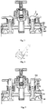
- FIG. 6 is an isometric sectional structure diagram of a first presser surface pressing against a paint bucket opening.
- Fig. 7 is an isometric sectional structure diagram of a second presser surface pressing against a paint bucket opening.
- the hand In the entire horizontal rotation process, the hand only needs to hold the handle part to avoid return of the cam, so that the compression spring is pressed continuously, and the working pressure of the finger is reduced, thereby saving physical work and facilitating operation.
- the paint bucket and the canister lid are in a sealed state, but are not shown in Fig. 7 .
- a bracket 27 is provided correspondingly above the through hole 21 of the canister lid 3; an upper flat plate of the bracket 27 is provided with a bracket through hole 271; the movable pipe sleeve 243 is placed in the bracket through hole 271; and the movable pipe sleeve 243 and the bracket through hole 271 are in sliding fit to each other.
- the whole pressing mechanism is supported by the upper through hole and the lower through hole, and is relatively firm.
- a reset spring 28 is sleeved at the outer periphery of the compression rod between the lower side of the canister lid and the presser foot. With this design, the pressing mechanism can be prevented from moving when the presser foot is in a relaxed state. There are two or four pressing mechanisms.
- At least three clamping jaws 29 are provided at the periphery of the canister lid. There are three or four clamping jaws 29.
- At least three clamping jaws 29 are provided at the periphery of the canister lid.
- the stirring canister lid is operated, the plurality of clamping jaws surround the outer side of the paint bucket, and the canister lid can be adjusted to be concentric to the paint bucket.
- Four clamping jaws are added to the new structure of the canister lid.
- center adjustment can be achieved to ensure the canister lid is centered, without manually adjusting the position of the canister lid to be centered, wherein four clamping jaws with the same size are uniformly distributed around the canister lid; and when canister lid is sleeved on the paint bucket, the four clamping jaws can be automatically pressed uniformly into a groove according to the outer diameter of the paint bucket, to ensure the canister lid is sleeved in a centered manner.
- the canister lid adopts a novel sealing structure suitable for a paint container and a canister lid, and comprises lid body in sealed connection with the container, and a knob, springs, a presser foot, a seal ring and the like for cooperative operation of an upper and a lower surface of the lid body.
- the lid body is provided with a special structure for installing the seal ring, the compressed spring and a locking support. With this structure, the three workpieces can be assembled and connected from bottom to top, and the compressed spring can bidirectionally tighten the seal ring at the lower end and the locking support at the upper end. Then, the double-segment presser foot and the reset spring are mounted at the lower end of the lid body.
- the two workpieces penetrate through the lid body and the afore-mentioned seal ring.
- the spring and other parts are connected to the knob at the upper end of the lid body.
- the presser foot is rotated, and contraction of the presser foot is controlled.
- a knob pressing platform is pressed down, and by using the cam lifting handle on the knob, the compressed spring and the locking support, the presser foot is lifted up, so that the seal ring and a lower edge 30 of a boss of the paint bucket opening completely fit to each other to achieve a sealing effect.
- the knob pressing platform is lifted up, the presser foot is pushed out by using the reset spring between the presser foot and the lid body, and then the cam lifting handle is rotated in a reversed direction to contract the presser foot, and the paint bucket can be changed.
- the present invention achieves automatic centering in canister lid product installation, and achieves separation of pressing and rotating operations in the canister installation.
- the operation is easy and quick.
- the present application is specially directed to the newest universal canister lid of the company.
- the new structure can adapt to paint buckets of most brands in the market, does not need secondary processing or adjustment and is highly universal.
- the canister lid is simple to operate and comfortable on the hand during operation, and eliminates the shortcoming that the hand is squeezed during pressing and rotating operations of the previous canister lids.
Landscapes
- Chemical & Material Sciences (AREA)
- Chemical Kinetics & Catalysis (AREA)
- Coating Apparatus (AREA)
- Closures For Containers (AREA)
Claims (7)
- Rührdeckel, der für verschiedene Farbtopföffnungen geeignet ist, umfassend einen Farbauslassmechanismus (1) zum Steuern einer auszugießenden Farbe und mindestens zwei Pressmechanismen (2) zum Pressen eines Farbeimers und eines Kanisterdeckels (3), wobei für jeden Pressmechanismus der Kanisterdeckel mit einem Durchgangsloch (21) versehen ist, eine Druckstange (22) das Durchgangsloch durchdringt, eine Dichtungshülse (23) den Presshebel (22) umhüllt, ein Flansch (231) der Dichtungshülse (23) gegen den Kanisterdeckel (3) gedrückt wird, eine Druckfeder (25) den Außenumfang der Druckstange (22) zwischen dem Flansch (231) der Dichtungshülse (23) und einem Griff (24) an einem oberen Ende der Druckstange (22) umhüllt und ein Presserfuß (26) an einem unteren Ende der Druckstange (22) vorgesehen ist, dadurch gekennzeichnet, dass die Presserfußfläche ringsektorförmig ist und entlang einer Verbindungslinie zwischen zwei Bogenlinien in Form von Ringsektoren mit einer vertikalen Fläche (261) versehen ist, und die vertikale Fläche (261) die Ringsektorfläche in zwei Presserfußflächen mit unterschiedlichen Höhen und in einer abgestuften Weise unterteilt.
- Rührdeckel, der für verschiedene Farbtopföffnungen geeignet ist, nach Anspruch 1, wobei der Griff an dem oberen Ende der Druckstange ein Nockenhebegriff (241) ist, der durch Anlenken des oberen Endes der Druckstange und einer Nocke gebildet ist, eine Nockenfläche (242) des Nockenhebegriffs (241) in Kontakt mit einer oberen Fläche eines Nockensitzes steht, der Nockensitz eine bewegliche Rohrhülse (243) ist, welche die Druckstange außen umhüllt, eine obere Fläche (244) der beweglichen Rohrhülse (243) in Kontakt mit der Nockenfläche (242) des Nockenhebegriffs steht, die bewegliche Rohrhülse (243) mit einem Flansch (2431) versehen ist, und das obere Ende der Druckfeder (25) an dem Flansch (2431) der beweglichen Rohrhülse (243) anliegt.
- Rührdeckel, der für verschiedene Farbtopföffnungen geeignet ist, nach Anspruch 2, wobei eine Halterung (27) entsprechend über dem Durchgangsloch (21) des Kanisterdeckels (3) vorgesehen ist, eine obere flache Platte der Halterung (27) mit einem Durchgangsloch (271) der Halterung versehen ist, die bewegliche Rohrhülse (243) in das Durchgangsloch (271) der Halterung eingesetzt ist, und die bewegliche Rohrhülse (243) und das Durchgangsloch (271) der Halterung in Gleitpassung zueinander stehen.
- Rührdeckel, der für verschiedene Farbtopföffnungen geeignet ist, nach Anspruch 3, wobei eine Rückstellfeder (28) den Außenumfang des Presshebels zwischen der Unterseite des Kanisterdeckels und dem Presserfuß umhüllt.
- Rührdeckel, der für verschiedene Farbtopföffnungen geeignet ist, nach einem der Ansprüche 1 - 4, wobei an dem Umfang des Kanisterdeckels mindestens drei Klemmbacken (29) vorgesehen sind.
- Rührdeckel, der für verschiedene Farbtopföffnungen geeignet ist, nach Anspruch 5, wobei zwei oder vier Pressmechanismen vorhanden sind.
- Rührdeckel, der für verschiedene Farbtopföffnungen geeignet ist, nach Anspruch 5, wobei drei oder vier Klemmbacken (29) vorhanden sind.
Applications Claiming Priority (2)
| Application Number | Priority Date | Filing Date | Title |
|---|---|---|---|
| CN201610598476.9A CN107661704B (zh) | 2016-07-27 | 2016-07-27 | 适用不同漆桶桶口的搅拌浆盖 |
| PCT/CN2017/094255 WO2018019224A1 (zh) | 2016-07-27 | 2017-07-25 | 适用不同漆桶桶口的搅拌浆盖 |
Publications (3)
| Publication Number | Publication Date |
|---|---|
| EP3492181A1 EP3492181A1 (de) | 2019-06-05 |
| EP3492181A4 EP3492181A4 (de) | 2020-04-01 |
| EP3492181B1 true EP3492181B1 (de) | 2021-01-27 |
Family
ID=61016119
Family Applications (1)
| Application Number | Title | Priority Date | Filing Date |
|---|---|---|---|
| EP17833527.9A Active EP3492181B1 (de) | 2016-07-27 | 2017-07-25 | Umrührdeckel für verschiedene farbtopföffnungen |
Country Status (4)
| Country | Link |
|---|---|
| US (1) | US11266961B2 (de) |
| EP (1) | EP3492181B1 (de) |
| CN (1) | CN107661704B (de) |
| WO (1) | WO2018019224A1 (de) |
Families Citing this family (2)
| Publication number | Priority date | Publication date | Assignee | Title |
|---|---|---|---|---|
| CN107661725B (zh) * | 2016-07-27 | 2020-06-09 | 郑州三华科技实业有限公司 | 省力搅拌浆盖 |
| CN114733433B (zh) * | 2022-03-10 | 2024-02-06 | 浙江汇锋智造科技有限公司 | 一种用于生产高阻隔封套材料的涂层配比设备 |
Family Cites Families (16)
| Publication number | Priority date | Publication date | Assignee | Title |
|---|---|---|---|---|
| FR2707258B1 (fr) * | 1993-07-06 | 1995-08-18 | Fillon Pichon Sa | Couvercle à cames pour la fermeture d'un pot de peinture et applications analogues. |
| FR2711580B1 (fr) * | 1993-10-25 | 1996-01-19 | Fas | Dispositif de fermeture des couvercles agitateurs des boîtes de teintes sur les machines d'agitation. |
| US5472277A (en) * | 1994-06-14 | 1995-12-05 | Dedoes Industries, Inc. | Paint can cover assembly |
| US6336740B1 (en) * | 2001-04-05 | 2002-01-08 | Dedoes Industries, Inc. | Cover assembly with improved locking feet |
| US6511218B2 (en) * | 2001-04-05 | 2003-01-28 | Dedoes Industries, Inc. | Cover assembly for a paint can |
| CN2595461Y (zh) * | 2002-12-18 | 2003-12-31 | 郑州三华科技实业有限公司 | 带有防脱压杆固定座的色漆桶浆盖 |
| CN2595706Y (zh) * | 2002-12-27 | 2003-12-31 | 郑州三华科技实业有限公司 | 口径可调的色漆桶用浆盖 |
| CN2853184Y (zh) * | 2005-10-18 | 2007-01-03 | 杨丽琴 | 送漆桶结构 |
| US8559518B2 (en) | 2008-06-30 | 2013-10-15 | Samsung Electronics Co., Ltd. | System and method for motion estimation of digital video using multiple recursion rules |
| KR200451535Y1 (ko) * | 2008-09-11 | 2010-12-21 | 대우조선해양 주식회사 | 대용량의 페인트 교반장치 |
| CN203020695U (zh) * | 2012-12-07 | 2013-06-26 | 沈如华 | 一种漆桶用浆盖 |
| FR3010983B1 (fr) * | 2013-09-24 | 2016-02-26 | Fillon Technologies | Couvercle a joint pour la fermeture d'une boite et ensemble comprenant une boite et couvercle du type precite |
| CN203791160U (zh) * | 2014-03-24 | 2014-08-27 | 肖根福罗格注胶技术(苏州工业园区)有限公司 | 注胶压力罐用快锁密封盖 |
| CN103964093B (zh) * | 2014-05-08 | 2016-04-06 | 安徽星马专用汽车有限公司 | 四爪料盖的料盖筋板、翻转耳板和锁环的组对装置 |
| CN105416808A (zh) * | 2015-12-03 | 2016-03-23 | 山西汾西重工有限责任公司 | 大端面密封包装箱箱盖压紧机构 |
| US10518944B2 (en) * | 2016-05-10 | 2019-12-31 | Pacific Market International, Llc | Drinking vessel lid assembly |
-
2016
- 2016-07-27 CN CN201610598476.9A patent/CN107661704B/zh active Active
-
2017
- 2017-07-25 US US16/320,849 patent/US11266961B2/en active Active
- 2017-07-25 EP EP17833527.9A patent/EP3492181B1/de active Active
- 2017-07-25 WO PCT/CN2017/094255 patent/WO2018019224A1/zh not_active Ceased
Non-Patent Citations (1)
| Title |
|---|
| None * |
Also Published As
| Publication number | Publication date |
|---|---|
| EP3492181A1 (de) | 2019-06-05 |
| US20190160486A1 (en) | 2019-05-30 |
| US11266961B2 (en) | 2022-03-08 |
| CN107661704A (zh) | 2018-02-06 |
| CN107661704B (zh) | 2020-06-09 |
| EP3492181A4 (de) | 2020-04-01 |
| WO2018019224A1 (zh) | 2018-02-01 |
Similar Documents
| Publication | Publication Date | Title |
|---|---|---|
| EP3153460B1 (de) | Behälter mit druckentlastungsventil | |
| CN202636678U (zh) | 电压力锅的排气装置 | |
| US11266961B2 (en) | Agitator lid suitable for different paint pot openings | |
| JP2598888B2 (ja) | 小樽口栓のための口開け装置 | |
| EP3492163B1 (de) | Arbeitssparende farbmischabdeckung | |
| CN103070598B (zh) | 一种便携式慢炖锅 | |
| JP2003125912A (ja) | ポットの栓構造 | |
| CN219602046U (zh) | 盖子和盛装容器 | |
| CN205758291U (zh) | 一种排气锁气汤锅 | |
| CN216059565U (zh) | 容器盖及容器 | |
| CN219720531U (zh) | 可调定量油壶 | |
| CN108497917B (zh) | 夹钳式压力锅 | |
| US4557669A (en) | Pumping apparatus | |
| CN111166162A (zh) | 具有开合、调档控制机构的压力锅 | |
| CN209090826U (zh) | 夹钳式压力锅 | |
| CN209107059U (zh) | 一种保温壶 | |
| CN207754944U (zh) | 咖啡壶及其壶盖与壶体配合结构 | |
| CN106495083A (zh) | 一种方便户外工作人员饮用桶装水的装置 | |
| CN221334117U (zh) | 一种便于密封的反应釜 | |
| CN203020695U (zh) | 一种漆桶用浆盖 | |
| CN217592604U (zh) | 一种壶盖及具有壶盖的保温水壶 | |
| CN210169740U (zh) | 高压锅 | |
| CN205731847U (zh) | 一种用于木板的移动灌胶装置 | |
| CN112006532B (zh) | 锅盖组件及烹饪器具 | |
| KR200336736Y1 (ko) | 압력솥의 뚜껑개폐장치 |
Legal Events
| Date | Code | Title | Description |
|---|---|---|---|
| STAA | Information on the status of an ep patent application or granted ep patent |
Free format text: STATUS: THE INTERNATIONAL PUBLICATION HAS BEEN MADE |
|
| PUAI | Public reference made under article 153(3) epc to a published international application that has entered the european phase |
Free format text: ORIGINAL CODE: 0009012 |
|
| STAA | Information on the status of an ep patent application or granted ep patent |
Free format text: STATUS: REQUEST FOR EXAMINATION WAS MADE |
|
| 17P | Request for examination filed |
Effective date: 20190225 |
|
| AK | Designated contracting states |
Kind code of ref document: A1 Designated state(s): AL AT BE BG CH CY CZ DE DK EE ES FI FR GB GR HR HU IE IS IT LI LT LU LV MC MK MT NL NO PL PT RO RS SE SI SK SM TR |
|
| AX | Request for extension of the european patent |
Extension state: BA ME |
|
| DAV | Request for validation of the european patent (deleted) | ||
| DAX | Request for extension of the european patent (deleted) | ||
| A4 | Supplementary search report drawn up and despatched |
Effective date: 20200303 |
|
| RIC1 | Information provided on ipc code assigned before grant |
Ipc: B44D 3/12 20060101ALI20200226BHEP Ipc: B05C 11/115 20060101AFI20200226BHEP |
|
| REG | Reference to a national code |
Ref country code: DE Ref legal event code: R079 Ref document number: 602017032257 Country of ref document: DE Free format text: PREVIOUS MAIN CLASS: B05C0011115000 Ipc: B44D0003080000 |
|
| GRAP | Despatch of communication of intention to grant a patent |
Free format text: ORIGINAL CODE: EPIDOSNIGR1 |
|
| STAA | Information on the status of an ep patent application or granted ep patent |
Free format text: STATUS: GRANT OF PATENT IS INTENDED |
|
| RIC1 | Information provided on ipc code assigned before grant |
Ipc: B44D 3/08 20060101AFI20200812BHEP Ipc: B05C 11/115 20060101ALI20200812BHEP Ipc: B44D 3/12 20060101ALI20200812BHEP |
|
| INTG | Intention to grant announced |
Effective date: 20200827 |
|
| GRAS | Grant fee paid |
Free format text: ORIGINAL CODE: EPIDOSNIGR3 |
|
| GRAA | (expected) grant |
Free format text: ORIGINAL CODE: 0009210 |
|
| STAA | Information on the status of an ep patent application or granted ep patent |
Free format text: STATUS: THE PATENT HAS BEEN GRANTED |
|
| AK | Designated contracting states |
Kind code of ref document: B1 Designated state(s): AL AT BE BG CH CY CZ DE DK EE ES FI FR GB GR HR HU IE IS IT LI LT LU LV MC MK MT NL NO PL PT RO RS SE SI SK SM TR |
|
| REG | Reference to a national code |
Ref country code: GB Ref legal event code: FG4D |
|
| REG | Reference to a national code |
Ref country code: CH Ref legal event code: EP |
|
| REG | Reference to a national code |
Ref country code: AT Ref legal event code: REF Ref document number: 1358010 Country of ref document: AT Kind code of ref document: T Effective date: 20210215 |
|
| REG | Reference to a national code |
Ref country code: IE Ref legal event code: FG4D |
|
| REG | Reference to a national code |
Ref country code: DE Ref legal event code: R096 Ref document number: 602017032257 Country of ref document: DE |
|
| REG | Reference to a national code |
Ref country code: NL Ref legal event code: MP Effective date: 20210127 |
|
| REG | Reference to a national code |
Ref country code: LT Ref legal event code: MG9D |
|
| REG | Reference to a national code |
Ref country code: AT Ref legal event code: MK05 Ref document number: 1358010 Country of ref document: AT Kind code of ref document: T Effective date: 20210127 |
|
| PG25 | Lapsed in a contracting state [announced via postgrant information from national office to epo] |
Ref country code: PT Free format text: LAPSE BECAUSE OF FAILURE TO SUBMIT A TRANSLATION OF THE DESCRIPTION OR TO PAY THE FEE WITHIN THE PRESCRIBED TIME-LIMIT Effective date: 20210527 Ref country code: NO Free format text: LAPSE BECAUSE OF FAILURE TO SUBMIT A TRANSLATION OF THE DESCRIPTION OR TO PAY THE FEE WITHIN THE PRESCRIBED TIME-LIMIT Effective date: 20210427 Ref country code: HR Free format text: LAPSE BECAUSE OF FAILURE TO SUBMIT A TRANSLATION OF THE DESCRIPTION OR TO PAY THE FEE WITHIN THE PRESCRIBED TIME-LIMIT Effective date: 20210127 Ref country code: FI Free format text: LAPSE BECAUSE OF FAILURE TO SUBMIT A TRANSLATION OF THE DESCRIPTION OR TO PAY THE FEE WITHIN THE PRESCRIBED TIME-LIMIT Effective date: 20210127 Ref country code: GR Free format text: LAPSE BECAUSE OF FAILURE TO SUBMIT A TRANSLATION OF THE DESCRIPTION OR TO PAY THE FEE WITHIN THE PRESCRIBED TIME-LIMIT Effective date: 20210428 Ref country code: BG Free format text: LAPSE BECAUSE OF FAILURE TO SUBMIT A TRANSLATION OF THE DESCRIPTION OR TO PAY THE FEE WITHIN THE PRESCRIBED TIME-LIMIT Effective date: 20210427 Ref country code: LT Free format text: LAPSE BECAUSE OF FAILURE TO SUBMIT A TRANSLATION OF THE DESCRIPTION OR TO PAY THE FEE WITHIN THE PRESCRIBED TIME-LIMIT Effective date: 20210127 |
|
| PG25 | Lapsed in a contracting state [announced via postgrant information from national office to epo] |
Ref country code: SE Free format text: LAPSE BECAUSE OF FAILURE TO SUBMIT A TRANSLATION OF THE DESCRIPTION OR TO PAY THE FEE WITHIN THE PRESCRIBED TIME-LIMIT Effective date: 20210127 Ref country code: RS Free format text: LAPSE BECAUSE OF FAILURE TO SUBMIT A TRANSLATION OF THE DESCRIPTION OR TO PAY THE FEE WITHIN THE PRESCRIBED TIME-LIMIT Effective date: 20210127 Ref country code: PL Free format text: LAPSE BECAUSE OF FAILURE TO SUBMIT A TRANSLATION OF THE DESCRIPTION OR TO PAY THE FEE WITHIN THE PRESCRIBED TIME-LIMIT Effective date: 20210127 Ref country code: LV Free format text: LAPSE BECAUSE OF FAILURE TO SUBMIT A TRANSLATION OF THE DESCRIPTION OR TO PAY THE FEE WITHIN THE PRESCRIBED TIME-LIMIT Effective date: 20210127 Ref country code: AT Free format text: LAPSE BECAUSE OF FAILURE TO SUBMIT A TRANSLATION OF THE DESCRIPTION OR TO PAY THE FEE WITHIN THE PRESCRIBED TIME-LIMIT Effective date: 20210127 |
|
| PG25 | Lapsed in a contracting state [announced via postgrant information from national office to epo] |
Ref country code: IS Free format text: LAPSE BECAUSE OF FAILURE TO SUBMIT A TRANSLATION OF THE DESCRIPTION OR TO PAY THE FEE WITHIN THE PRESCRIBED TIME-LIMIT Effective date: 20210527 |
|
| REG | Reference to a national code |
Ref country code: DE Ref legal event code: R097 Ref document number: 602017032257 Country of ref document: DE |
|
| PG25 | Lapsed in a contracting state [announced via postgrant information from national office to epo] |
Ref country code: EE Free format text: LAPSE BECAUSE OF FAILURE TO SUBMIT A TRANSLATION OF THE DESCRIPTION OR TO PAY THE FEE WITHIN THE PRESCRIBED TIME-LIMIT Effective date: 20210127 Ref country code: CZ Free format text: LAPSE BECAUSE OF FAILURE TO SUBMIT A TRANSLATION OF THE DESCRIPTION OR TO PAY THE FEE WITHIN THE PRESCRIBED TIME-LIMIT Effective date: 20210127 Ref country code: SM Free format text: LAPSE BECAUSE OF FAILURE TO SUBMIT A TRANSLATION OF THE DESCRIPTION OR TO PAY THE FEE WITHIN THE PRESCRIBED TIME-LIMIT Effective date: 20210127 |
|
| PG25 | Lapsed in a contracting state [announced via postgrant information from national office to epo] |
Ref country code: SK Free format text: LAPSE BECAUSE OF FAILURE TO SUBMIT A TRANSLATION OF THE DESCRIPTION OR TO PAY THE FEE WITHIN THE PRESCRIBED TIME-LIMIT Effective date: 20210127 Ref country code: DK Free format text: LAPSE BECAUSE OF FAILURE TO SUBMIT A TRANSLATION OF THE DESCRIPTION OR TO PAY THE FEE WITHIN THE PRESCRIBED TIME-LIMIT Effective date: 20210127 Ref country code: RO Free format text: LAPSE BECAUSE OF FAILURE TO SUBMIT A TRANSLATION OF THE DESCRIPTION OR TO PAY THE FEE WITHIN THE PRESCRIBED TIME-LIMIT Effective date: 20210127 |
|
| PLBE | No opposition filed within time limit |
Free format text: ORIGINAL CODE: 0009261 |
|
| STAA | Information on the status of an ep patent application or granted ep patent |
Free format text: STATUS: NO OPPOSITION FILED WITHIN TIME LIMIT |
|
| 26N | No opposition filed |
Effective date: 20211028 |
|
| PG25 | Lapsed in a contracting state [announced via postgrant information from national office to epo] |
Ref country code: AL Free format text: LAPSE BECAUSE OF FAILURE TO SUBMIT A TRANSLATION OF THE DESCRIPTION OR TO PAY THE FEE WITHIN THE PRESCRIBED TIME-LIMIT Effective date: 20210127 Ref country code: ES Free format text: LAPSE BECAUSE OF FAILURE TO SUBMIT A TRANSLATION OF THE DESCRIPTION OR TO PAY THE FEE WITHIN THE PRESCRIBED TIME-LIMIT Effective date: 20210127 |
|
| REG | Reference to a national code |
Ref country code: DE Ref legal event code: R119 Ref document number: 602017032257 Country of ref document: DE |
|
| PG25 | Lapsed in a contracting state [announced via postgrant information from national office to epo] |
Ref country code: SI Free format text: LAPSE BECAUSE OF FAILURE TO SUBMIT A TRANSLATION OF THE DESCRIPTION OR TO PAY THE FEE WITHIN THE PRESCRIBED TIME-LIMIT Effective date: 20210127 |
|
| REG | Reference to a national code |
Ref country code: CH Ref legal event code: PL |
|
| GBPC | Gb: european patent ceased through non-payment of renewal fee |
Effective date: 20210725 |
|
| PG25 | Lapsed in a contracting state [announced via postgrant information from national office to epo] |
Ref country code: MC Free format text: LAPSE BECAUSE OF FAILURE TO SUBMIT A TRANSLATION OF THE DESCRIPTION OR TO PAY THE FEE WITHIN THE PRESCRIBED TIME-LIMIT Effective date: 20210127 |
|
| REG | Reference to a national code |
Ref country code: BE Ref legal event code: MM Effective date: 20210731 |
|
| PG25 | Lapsed in a contracting state [announced via postgrant information from national office to epo] |
Ref country code: LI Free format text: LAPSE BECAUSE OF NON-PAYMENT OF DUE FEES Effective date: 20210731 Ref country code: GB Free format text: LAPSE BECAUSE OF NON-PAYMENT OF DUE FEES Effective date: 20210725 Ref country code: DE Free format text: LAPSE BECAUSE OF NON-PAYMENT OF DUE FEES Effective date: 20220201 Ref country code: CH Free format text: LAPSE BECAUSE OF NON-PAYMENT OF DUE FEES Effective date: 20210731 |
|
| PG25 | Lapsed in a contracting state [announced via postgrant information from national office to epo] |
Ref country code: IS Free format text: LAPSE BECAUSE OF FAILURE TO SUBMIT A TRANSLATION OF THE DESCRIPTION OR TO PAY THE FEE WITHIN THE PRESCRIBED TIME-LIMIT Effective date: 20210527 Ref country code: LU Free format text: LAPSE BECAUSE OF NON-PAYMENT OF DUE FEES Effective date: 20210725 |
|
| PG25 | Lapsed in a contracting state [announced via postgrant information from national office to epo] |
Ref country code: IE Free format text: LAPSE BECAUSE OF NON-PAYMENT OF DUE FEES Effective date: 20210725 Ref country code: BE Free format text: LAPSE BECAUSE OF NON-PAYMENT OF DUE FEES Effective date: 20210731 |
|
| PG25 | Lapsed in a contracting state [announced via postgrant information from national office to epo] |
Ref country code: NL Free format text: LAPSE BECAUSE OF NON-PAYMENT OF DUE FEES Effective date: 20210127 Ref country code: CY Free format text: LAPSE BECAUSE OF FAILURE TO SUBMIT A TRANSLATION OF THE DESCRIPTION OR TO PAY THE FEE WITHIN THE PRESCRIBED TIME-LIMIT Effective date: 20210127 |
|
| PG25 | Lapsed in a contracting state [announced via postgrant information from national office to epo] |
Ref country code: HU Free format text: LAPSE BECAUSE OF FAILURE TO SUBMIT A TRANSLATION OF THE DESCRIPTION OR TO PAY THE FEE WITHIN THE PRESCRIBED TIME-LIMIT; INVALID AB INITIO Effective date: 20170725 |
|
| PG25 | Lapsed in a contracting state [announced via postgrant information from national office to epo] |
Ref country code: MK Free format text: LAPSE BECAUSE OF FAILURE TO SUBMIT A TRANSLATION OF THE DESCRIPTION OR TO PAY THE FEE WITHIN THE PRESCRIBED TIME-LIMIT Effective date: 20210127 |
|
| PG25 | Lapsed in a contracting state [announced via postgrant information from national office to epo] |
Ref country code: TR Free format text: LAPSE BECAUSE OF FAILURE TO SUBMIT A TRANSLATION OF THE DESCRIPTION OR TO PAY THE FEE WITHIN THE PRESCRIBED TIME-LIMIT Effective date: 20210127 |
|
| PG25 | Lapsed in a contracting state [announced via postgrant information from national office to epo] |
Ref country code: MT Free format text: LAPSE BECAUSE OF FAILURE TO SUBMIT A TRANSLATION OF THE DESCRIPTION OR TO PAY THE FEE WITHIN THE PRESCRIBED TIME-LIMIT Effective date: 20210127 |
|
| PGFP | Annual fee paid to national office [announced via postgrant information from national office to epo] |
Ref country code: FR Payment date: 20250626 Year of fee payment: 9 |
|
| PGFP | Annual fee paid to national office [announced via postgrant information from national office to epo] |
Ref country code: IT Payment date: 20250731 Year of fee payment: 9 |